JP4276258B2 - System and method for implementing sample rate converters using hardware and software to maximize speed and flexibility - Google Patents
System and method for implementing sample rate converters using hardware and software to maximize speed and flexibility Download PDFInfo
- Publication number
- JP4276258B2 JP4276258B2 JP2006507404A JP2006507404A JP4276258B2 JP 4276258 B2 JP4276258 B2 JP 4276258B2 JP 2006507404 A JP2006507404 A JP 2006507404A JP 2006507404 A JP2006507404 A JP 2006507404A JP 4276258 B2 JP4276258 B2 JP 4276258B2
- Authority
- JP
- Japan
- Prior art keywords
- sample rate
- data stream
- sample
- input data
- rate converter
- Prior art date
- Legal status (The legal status is an assumption and is not a legal conclusion. Google has not performed a legal analysis and makes no representation as to the accuracy of the status listed.)
- Expired - Fee Related
Links
Images


Classifications
-
- H—ELECTRICITY
- H03—ELECTRONIC CIRCUITRY
- H03F—AMPLIFIERS
- H03F1/00—Details of amplifiers with only discharge tubes, only semiconductor devices or only unspecified devices as amplifying elements
- H03F1/52—Circuit arrangements for protecting such amplifiers
- H03F1/523—Circuit arrangements for protecting such amplifiers for amplifiers using field-effect devices
-
- H—ELECTRICITY
- H03—ELECTRONIC CIRCUITRY
- H03F—AMPLIFIERS
- H03F3/00—Amplifiers with only discharge tubes or only semiconductor devices as amplifying elements
- H03F3/20—Power amplifiers, e.g. Class B amplifiers, Class C amplifiers
- H03F3/21—Power amplifiers, e.g. Class B amplifiers, Class C amplifiers with semiconductor devices only
- H03F3/217—Class D power amplifiers; Switching amplifiers
- H03F3/2171—Class D power amplifiers; Switching amplifiers with field-effect devices
-
- H—ELECTRICITY
- H03—ELECTRONIC CIRCUITRY
- H03F—AMPLIFIERS
- H03F3/00—Amplifiers with only discharge tubes or only semiconductor devices as amplifying elements
- H03F3/20—Power amplifiers, e.g. Class B amplifiers, Class C amplifiers
- H03F3/21—Power amplifiers, e.g. Class B amplifiers, Class C amplifiers with semiconductor devices only
- H03F3/217—Class D power amplifiers; Switching amplifiers
- H03F3/2175—Class D power amplifiers; Switching amplifiers using analogue-digital or digital-analogue conversion
-
- H—ELECTRICITY
- H03—ELECTRONIC CIRCUITRY
- H03G—CONTROL OF AMPLIFICATION
- H03G7/00—Volume compression or expansion in amplifiers
- H03G7/007—Volume compression or expansion in amplifiers of digital or coded signals
-
- H—ELECTRICITY
- H03—ELECTRONIC CIRCUITRY
- H03H—IMPEDANCE NETWORKS, e.g. RESONANT CIRCUITS; RESONATORS
- H03H17/00—Networks using digital techniques
- H03H17/02—Frequency selective networks
- H03H17/06—Non-recursive filters
- H03H17/0621—Non-recursive filters with input-sampling frequency and output-delivery frequency which differ, e.g. extrapolation; Anti-aliasing
-
- H—ELECTRICITY
- H04—ELECTRIC COMMUNICATION TECHNIQUE
- H04L—TRANSMISSION OF DIGITAL INFORMATION, e.g. TELEGRAPHIC COMMUNICATION
- H04L7/00—Arrangements for synchronising receiver with transmitter
- H04L7/0016—Arrangements for synchronising receiver with transmitter correction of synchronization errors
- H04L7/005—Correction by an elastic buffer
-
- H—ELECTRICITY
- H04—ELECTRIC COMMUNICATION TECHNIQUE
- H04L—TRANSMISSION OF DIGITAL INFORMATION, e.g. TELEGRAPHIC COMMUNICATION
- H04L7/00—Arrangements for synchronising receiver with transmitter
- H04L7/02—Speed or phase control by the received code signals, the signals containing no special synchronisation information
-
- H—ELECTRICITY
- H03—ELECTRONIC CIRCUITRY
- H03F—AMPLIFIERS
- H03F2200/00—Indexing scheme relating to amplifiers
- H03F2200/331—Sigma delta modulation being used in an amplifying circuit
-
- H—ELECTRICITY
- H03—ELECTRONIC CIRCUITRY
- H03H—IMPEDANCE NETWORKS, e.g. RESONANT CIRCUITS; RESONATORS
- H03H2218/00—Indexing scheme relating to details of digital filters
- H03H2218/06—Multiple-input, multiple-output [MIMO]; Multiple-input, single-output [MISO]
Abstract
Description
発明の属する技術分野
本発明は、一般的に音響増幅システムに関し、特に、第1のサンプルレートを有する入力データストリームを第2のデータレートを有する出力データストリームに変換するシステム及び方法に関する。
The present invention relates generally to acoustic amplification systems, and more particularly to a system and method for converting an input data stream having a first sample rate into an output data stream having a second data rate.
関連技術
パルス幅変調(PWM)あるいはD級信号増幅技術は長年存在するが、スイッチドモード電源(SMPS)の増加に伴っていっそうポピュラーになってきている。この技術が現れてから、信号増幅アプリケーションにPWM技術を適用することへの関心が高まってきた。これは、少なくとも部分的に、昔の(リニアなAB級)電力出力トポロジィに代わるD級電力出力トポロジィの使用を通じて認識することができるかなりの効率改善の結果である。
Related Art Although pulse width modulation (PWM) or class D signal amplification technology has existed for many years, it has become increasingly popular with the increase in switched mode power supplies (SMPS). Since the emergence of this technology, there has been increased interest in applying PWM technology to signal amplification applications. This is at least partly the result of considerable efficiency improvements that can be recognized through the use of class D power output topologies instead of the old (linear class AB) power output topologies.
信号増幅アプリケーションを開発する初期の試みは、初期のSMPSで用いられていた増幅と同じアプローチを用いていた。特に、これらの試みはアナログ変調スキームに用いられ、性能が大変低いアプリケーションであった。これらのアプリケーションは非常に複雑であって、実装にコストがかかるものであった。その結果、これらの解決法は広く受け入れられなかった。このため従来のD級アナログ実装技術は、昔のAB級増幅器に代わる主流の増幅器アプリケーションにならなかった。 Early attempts to develop signal amplification applications used the same approach as the amplification used in early SMPS. In particular, these attempts were used in analog modulation schemes and were very poor performance applications. These applications were very complex and expensive to implement. As a result, these solutions have not been widely accepted. For this reason, the conventional class D analog mounting technology has not become a mainstream amplifier application replacing the old class AB amplifier.
近年、デジタルPWM変調スキームが浮上してきた。これらのスキームはシグマ−デルタ変調技術を用いて、より新しいデジタルD級の実装に用いるPWM信号を発生する。しかしながら、これらのデジタルPWMスキームは、PWM変調器を増幅器ソリューション全体に一体化することに対する主バリアをわずかにオフセットするだけである。したがってD級技術はいまだに、昔のAB級増幅器に代わって主流のアプリケーションになることができない。 In recent years, digital PWM modulation schemes have emerged. These schemes use sigma-delta modulation techniques to generate PWM signals for use in newer digital class D implementations. However, these digital PWM schemes only slightly offset the main barrier to integrating the PWM modulator into the entire amplifier solution. Thus, Class D technology still cannot become a mainstream application in place of the old Class AB amplifier.
現存のデジタルPWM変調スキームにはいくつもの問題がある。この問題の一つは、残りの部分の信号処理システムの性能と品質特性がアプリケーションによって異なることである。トータルシステムソリューションとエンドユーザアプリケーションの正しい実装は決定的なものではない。この結果、実装の詳細をアプリオリに説明することができない。現存の技術はアプリケーションを特定したソリューションを要求するので、このソリューションは通常フレキシブルでなく、スケーラブルでなく、また他のアプリケーションに転用することができない。この結果、一般にこれらの技術は主流システムに適用することができない。 There are a number of problems with existing digital PWM modulation schemes. One problem is that the performance and quality characteristics of the rest of the signal processing system vary from application to application. The correct implementation of total system solutions and end-user applications is not critical. As a result, implementation details cannot be explained a priori. Because existing technologies require application-specific solutions, these solutions are usually not flexible, scalable, or transferable to other applications. As a result, these techniques generally cannot be applied to mainstream systems.
特に現存のデジタルPWM変調スキームが主流システムの要求に合わない領域は、様々なサンプルレートを有するデジタル入力データストリームの処理である。これらの入力データストリームは、特別なデバイスのデザインと同様に、データを提供するデバイスのタイプによって異なるサンプルレートを有している。入力データストリームが、若干レートが異なっていたり、あるいは互いにドリフトするクロックソースを用いることもある。現存の技術は単一のサンプルレートか、あるいは複数の固定された既知の入力レートを要求しており、デバイスが提供する入力データのレートが異なることに適応することができない。 In particular, an area where existing digital PWM modulation schemes do not meet the requirements of mainstream systems is the processing of digital input data streams with varying sample rates. These input data streams have different sample rates depending on the type of device providing the data, as well as special device designs. The input data streams may use clock sources that are slightly different in rate or drift with respect to each other. Existing techniques require a single sample rate or multiple fixed known input rates, and cannot accommodate the different rates of input data provided by the device.
従来のシステムの別の問題点は、システムがローカルクロック信号を発生できるサンプルレートコンバータを有していないので、通常、入力データからPWMクロック信号を再生していることである。この再生したクロック信号は、局部的に発生したクロック信号でサポートするより高い性能をサポートすることができない。 Another problem with conventional systems is that, since the system does not have a sample rate converter that can generate a local clock signal, the PWM clock signal is usually recovered from the input data. This regenerated clock signal cannot support higher performance than is supported by a locally generated clock signal.
発明の概要
上記に概要を説明した一又はそれ以上の問題点は、本発明の様々な実施例によって解決することができる。広く言えば、本発明は、ハードウエアとソフトウエア部品の組み合わせを用いてデジタル入力データストリームを第1のサンプルレートから第2のサンプルレートへ変換するシステムと方法を具える。一の実施例では、第1のサンプルレートから第2のサンプルレートへの変換が、デジタル音響システム用のサンプルレートコンバータ内で実行される。サンプルレートコンバータは複数の部品を有し、そのうちのいくつかはハードウエアに実装されており、いくつかはソフトウエアに実装されている。各部品をハードウエアに実装するかソフトウエアに実装するかは、部品の性能要求による。ソフトウエアでより優れた性能を実現する部品はソフトウエアに実装し、ハードウエアでより優れた性能を実現する部品はハードウエアに実装する。音響パフォーマンス手段の性能のみならず、コンピュータの複雑性、すなわちソフトウエアエンジンの部品の「適合性」における性能も改善することができる。
SUMMARY OF THE INVENTION One or more of the problems outlined above can be solved by various embodiments of the present invention. Broadly speaking, the present invention comprises a system and method for converting a digital input data stream from a first sample rate to a second sample rate using a combination of hardware and software components. In one embodiment, the conversion from the first sample rate to the second sample rate is performed in a sample rate converter for a digital audio system. The sample rate converter has a plurality of components, some of which are implemented in hardware and some are implemented in software. Whether each component is mounted on hardware or software depends on the performance requirements of the component. Components that achieve better performance in software are implemented in software, and components that achieve better performance in hardware are implemented in hardware. Not only the performance of the acoustic performance means, but also the complexity of the computer, ie the “compatibility” of the software engine components, can be improved.
一の実施例は、入力データストリームのサンプルレートを予測するように構成されたレートエスティメータと、この予測されたサンプルレートに基づいて多段階フィルタ係数セットの補間用の位相を選択するように構成された位相選択ユニットと、この選択された位相に基づいてフィルタ係数を補間することによって位相解像度を上げるように構成された係数インターポレータと、この補間されたフィルタ係数を入力データストリームのサンプルで重畳して再サンプリングされた出力データストリームのサンプルを生成するように構成された重畳ユニットとを具えるサンプルレートコンバータシステムを具える。上述したとおり、これらのシステム部品は、ハードウエア部品とソフトウエア部品の双方を具える。一の実施例では、このシステムは2又はそれ以上のチャネルを具え、各チャネルが、他のチャネルが受信したデータストリームと異なる可変サンプルレートを有する入力データストリームを受信することができる。一の実施例では、この異なるチャネルが一又はそれ以上の共通部品を他のチャネルと共用している。一の実施例では、サンプルレートコンバータシステムが音響増幅システムに接続されており、入力データストリームを、音響効果ユニットあるいはパルス幅変調器などの増幅部品によって処理するための共通の出力サンプルレートに変換するように構成されている。 One embodiment is configured to select a rate estimator configured to predict a sample rate of an input data stream and a phase for interpolation of a multi-stage filter coefficient set based on the predicted sample rate. Phase selection unit, a coefficient interpolator configured to increase phase resolution by interpolating filter coefficients based on the selected phase, and the interpolated filter coefficients in samples of the input data stream A sample rate converter system comprising a superposition unit configured to generate samples of the output data stream that are superposed and resampled. As described above, these system components include both hardware and software components. In one embodiment, the system comprises two or more channels, each channel capable of receiving an input data stream having a variable sample rate that is different from the data stream received by the other channels. In one embodiment, the different channels share one or more common components with other channels. In one embodiment, a sample rate converter system is connected to the sound amplification system and converts the input data stream to a common output sample rate for processing by an amplification component such as a sound effects unit or a pulse width modulator. It is configured as follows.
別の実施例は、入力サンプルレートを有する入力データストリームを受信するステップと、ハードウエアとソフトウエア部品の組み合わせを用いてこの入力データストリームを処理して入力サンプルレートと異なる出力サンプルレートを有する出力データストリームを生成するステップを具える方法を具える。一の実施例では、この処理ステップが、入力サンプルレートを予測するステップと、多段階フィルタ係数セットの補間用の位相を選択するステップと、多段階フィルタ係数セットを補間するステップと、補間された多段階フィルタ係数セットを入力データストリームのサンプルで重畳するステップと、出力データストリームの結果としてのサンプルを提供するステップとを具える。一の実施例では、この方法は、独立した可変サンプルレートを別々のチャネルに有する2又はそれ以上の入力データストリームを処理して共通の出力サンプルレートを有する対応する出力データストリームを生成するステップとを具える。異なるデータストリームを異なるチャネルで処理するステップの少なくとも一部は、共通部品あるいはソフトウエア部品内で実行される。 Another embodiment includes receiving an input data stream having an input sample rate and processing the input data stream using a combination of hardware and software components to output an output sample rate different from the input sample rate. A method comprising the step of generating a data stream. In one embodiment, the processing steps are interpolated, predicting the input sample rate, selecting a phase for interpolation of the multi-stage filter coefficient set, interpolating the multi-stage filter coefficient set, Superimposing a multi-stage filter coefficient set with samples of the input data stream and providing samples as a result of the output data stream. In one embodiment, the method includes processing two or more input data streams having independent variable sample rates on separate channels to generate corresponding output data streams having a common output sample rate; With At least some of the steps of processing different data streams on different channels are performed in a common component or software component.
様々な追加の実施例も可能である。 Various additional embodiments are possible.
ハードウエアとソフトウエア部品の双方を使用することは、従来のシステムを超えた様々な利点を提供することができる。一の潜在的な利点は、処理スピードが重要である部品を専用のハードウエアに実装してその性能を最大にすることができ、一方で、フレキシビリティがより重要な別の部品をソフトウエアに実装することができる。その他の潜在的な利点は、ハードウエア部品及び/又はソフトウエア部品が複数チャネルに共通であり(共用されている)、これによってシステムのコストと複雑性を低減できる一方で、システムの速度とフレキシビリティを保つことができる点である。その他の潜在的な利点は、可変であり、その他のチャネルのデータストリームのサンプルレートから独立している入力サンプルレートを、各チャネルで操作可能である点である。その他の潜在的な利点は、局部的な高パフォーマンスのクロック信号を生成することによって、クロック信号が入力データから再生されなくてはならない場合より高いパフォーマンス標準にPWM出力を合わせることができる点である。 Using both hardware and software components can provide various advantages over conventional systems. One potential advantage is that components where processing speed is important can be implemented on dedicated hardware to maximize their performance, while another component where flexibility is more important is made into software. Can be implemented. Another potential advantage is that hardware and / or software components are common (shared) across multiple channels, which can reduce system cost and complexity, while reducing system speed and flexibility. It is a point that can maintain the ability. Another potential advantage is that each channel can be operated with an input sample rate that is variable and independent of the sample rate of the data streams of the other channels. Another potential advantage is that by generating a local high performance clock signal, the PWM output can be tuned to a higher performance standard than if the clock signal had to be recovered from the input data. .
本発明の様々な変形例や代替例が示されており、その特定の実施例が図面および明細書に例として記載されている。図面および詳細な説明は、本発明をここに述べた特定の実施例に限定する意図ではない。この開示は、請求の範囲に規定されている本発明の範囲に入るすべての変形例、均等物及び代替例をカバーするものである。 Various variations and alternatives of the invention are shown, specific examples of which are illustrated by way of example in the drawings and specification. The drawings and detailed description are not intended to limit the invention to the specific embodiments described herein. This disclosure is intended to cover all modifications, equivalents, and alternatives falling within the scope of the invention as defined by the claims.
実施例の詳細な説明
本発明の一又はそれ以上の実施例を以下に説明する。これらの実施例及び以下に述べるその他のすべての実施例は具体例であり、本発明を限定するものではなく明確化するためのものである。
Detailed Description of the Embodiments One or more embodiments of the present invention are described below. These examples and all other examples described below are illustrative and are not intended to limit the invention, but to clarify it.
ここに述べるように、本発明の様々実施例はハードウエア部品とソフトウエア部品の組み合わせを用いてデジタル入力データストリームを第1のサンプルレートから第2のサンプルレートへ変換するシステム及び方法を具える。ここに使用されているとおり、「ハードウエア」とは専用の、固定された機能ロジックを意味する。一方、「ソフトウエア」はプログラマによって規定されたアルゴリズムで制御されるプログラム可能なロジック、あるいは、デジタル信号プロセッサ(DSP),論理演算装置(ALU)、あるいはメモリにあるような、一般的なソフトウエアに基づくプログラム可能なブロックの使用を意味する。 As described herein, various embodiments of the present invention comprise systems and methods for converting a digital input data stream from a first sample rate to a second sample rate using a combination of hardware and software components. . As used herein, “hardware” means dedicated, fixed functional logic. On the other hand, “software” is programmable logic controlled by an algorithm defined by a programmer, or general software such as a digital signal processor (DSP), an arithmetic logic unit (ALU), or a memory. Means the use of programmable blocks based on.
一の実施例では、第1のサンプルレートから第2のサンプルレートへの変換が、デジタル音響システム用のサンプルレートコンバータにおいて実行される。サンプルレートコンバータは複数の部品を有しており、このうちのいくつかはハードウエアに実装されており、いくつかはソフトウエアに実装されている。各部品をハードウエアに実装するか、ソフトウエアに実装するかは、部品の性能要求による。ソフトウエアでよりよいパフォーマンスを達成する部品はソフトウエアに実装され、ハードウエアでよりよいパフォーマンスを達成する部品はハードウエアに実装される。上述したとおり、パフォーマンスは音響パフォーマンス、コンピュータの複雑性、その他に関して、動作に要求されるプロセッササイクル数、デバイスサイズ、実装コスト、フレキシビリティ、消費電力などの測定基準を用いて測定することができる。 In one embodiment, the conversion from the first sample rate to the second sample rate is performed in a sample rate converter for a digital audio system. The sample rate converter has a plurality of parts, some of which are implemented in hardware and some are implemented in software. Whether each component is mounted on hardware or software depends on the performance requirements of the component. Components that achieve better performance in software are implemented in software, and components that achieve better performance in hardware are implemented in hardware. As described above, performance can be measured using metrics such as the number of processor cycles required for operation, device size, implementation cost, flexibility, power consumption, etc. with respect to acoustic performance, computer complexity, etc.
ハードウエアとソフトウエアの両方を使用することは、ハードウエアに全部を実装するかソフトウエアに全部を実装している従来のシステムに比していくつもの利点を提供するものである。例えば、処理スピードが重要な部品は専用のハードウエアに実装してそのパフォーマンスを最大にすることができる。その他の部品については、処理スピードがフレキシビリティより重要ではない。これらの部品は所望のフレキシビリティを提供するためにソフトウエアに実装することができる。ハードウエア部品とソフトウエア部品を両方使用することの更なる利点は、部品のいくつかを複数チャネルに用いることができることである。チャネル間で部品のいくつかを共用することによって、システムのスピードとフレキシビリティを維持しながらシステムのコストと複雑性を低減できる。 Using both hardware and software offers a number of advantages over conventional systems that are either fully implemented in hardware or entirely in software. For example, a component whose processing speed is important can be mounted on dedicated hardware to maximize its performance. For other parts, processing speed is less important than flexibility. These components can be implemented in software to provide the desired flexibility. A further advantage of using both hardware and software components is that some of the components can be used for multiple channels. Sharing some of the components between channels can reduce system cost and complexity while maintaining system speed and flexibility.
本発明の好ましい実施例は、音響増幅システムに実装されている。上述したとおり、パルス幅変調(PWM)技術が近年音響増幅システムに適用されてきているが、従来の方法論には欠点があった。これらの方法論は、複雑でコストがかかり、比較的パフォーマンスが貧弱なアナログ変調スキームを用いている。本発明のシステムと方法は、これに変えてデジタル変調スキームが実装されており、従来の技術のいくつかの問題点を解決する方法論を用いている。 The preferred embodiment of the present invention is implemented in an acoustic amplification system. As described above, pulse width modulation (PWM) technology has been applied to acoustic amplification systems in recent years, but conventional methodologies have drawbacks. These methodologies use analog modulation schemes that are complex, costly, and have relatively poor performance. The system and method of the present invention instead implements a digital modulation scheme and uses a methodology that solves some of the problems of the prior art.
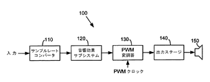
図1を参照すると、PWM技術を用いたデジタル音響増幅システムを示す機能ブロック図が示されている。この実施例では、システム100は、CDプレーヤ、MP3プレーヤ、デジタル音響テープ、その他のデータソースからデジタル入力データストリームを受信する。入力データストリームはサンプルレートコンバータ110によって受信される。入力データストリームはデータソースに応じた特定のサンプルレートを有する。このサンプルレートは、通常、対応するデバイスタイプによって使用される所定のサンプルレートセットのうちの一つである。例えば、CDプレーヤは44.1kHzのサンプルレートでデジタルデータを出力するが、デジタル音響テーププレーヤは、32kHzのサンプルレートでデータを出力する。
Referring to FIG. 1, a functional block diagram illustrating a digital sound amplification system using PWM technology is shown. In this example,
本発明のシステム及び方法では、サンプルレートコンバータ110が、入力データストリームを受信したサンプルレートからシステム100で用いられている所定の内部レートに変換する。一の実施例では、この内部サンプルレートは100kHzである。したがって、50kHzのサンプルレートでデータが受信される場合は、サンプルレートコンバータ110はこのデータを再度サンプリングして、100kHzのサンプルレートで対応する内部データストリームを生成する。この内部データストリームは、次いで音響効果サブシステム120に送られる。音響効果サブシステム120は、内部データストリームに所望の処理を行って、結果としての処理データストリームをPWM変調器130に提供する。
In the system and method of the present invention, the
PWM変調器130によって受信されたデータストリームは、パルスコード変調信号を表している。PWM変調器130は、このデータストリームをパルス幅変調信号に変換する。パルス幅変調信号は、次いで、出力ステージ140に提供される。出力ステージ140において、パルス幅変調信号を増幅し、増幅した信号をろ波したり、更に処理したりすることができる。この結果としての信号がスピーカシステム150に出力され、ここで電気信号を可聴信号に変換して聴者が聞くことができるようにする。
The data stream received by the
本発明の開示は、上述した音響システムのサンプルレートコンバータに焦点を当てている。上述したとおり、サンプルレートコンバータの目的は、第1のレートでサンプリングされる入力データストリームを受信することと、第2のサンプルレートでサンプリングされる出力データストリームを生成することである。データストリームで表される音響信号が実質的に変わることがないが(少なくともいくつかの実施例において)、サンプリングレートは、システムで処理することができるように音響システムの要求に合うように変化する。 The present disclosure focuses on the sample rate converter of the acoustic system described above. As described above, the purpose of the sample rate converter is to receive an input data stream that is sampled at a first rate and to generate an output data stream that is sampled at a second sample rate. Although the acoustic signal represented by the data stream does not change substantially (in at least some embodiments), the sampling rate varies to meet the requirements of the acoustic system so that it can be processed by the system. .
図2を参照すると、典型的なサンプルレートの変換方法を示す図が示されている。この図に示すとおり、入力データストリームは、第1フィルタ210によって、まず、アップサンプリングされるか、あるいは補間され、第2フィルタ220によってダウンサンプリングされるか、あるいはデシメートされる。中間フィルタ230を用いてアップサンプリングしたデータをデシメートする前に低域ろ波する。入力データストリームは第1のサンプルレートFinを有する。このデータストリームは、ファクタMによってアップサンプリングされる。したがって、アップサンプリングされた後、このデータストリームはM×Finのサンプルレートを有する。アップサンプリングは、通常、入力データストリームのサンプル間を補間して中間サンプルを発生することによって行われる。Mは、中間サンプルレート(M×Fin)が所望の出力サンプルレートFoutより高くなるように選択される。通常は、この中間レートは所望の出力レートより高い。
Referring to FIG. 2, a diagram illustrating a typical sample rate conversion method is shown. As shown in this figure, the input data stream is first upsampled or interpolated by the
アップサンプリングされたデータストリームは、低域ろ波され、ついで、サンプルレートを中間レートから所望の出力レートにするためにデシメートされる。ダウンサンプリングした後、サンプルレートはFout=(M/N)×Finになる。データストリームのダウンサンプリング、あるいはデシメーションは、通常、中間データストリームからサンプルをドロッピングすることによって行われる。例えば、中間データストリームが200kHzでサンプリングされ、所望の出力サンプルレートが100kHzである場合、ほかのサンプルはすべてドロップされる。 The upsampled data stream is low pass filtered and then decimated to change the sample rate from the intermediate rate to the desired output rate. After downsampling, the sample rate is Fout = (M / N) × Fin. Downsampling or decimation of the data stream is usually done by dropping samples from the intermediate data stream. For example, if the intermediate data stream is sampled at 200 kHz and the desired output sample rate is 100 kHz, all other samples are dropped.
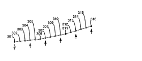
理想的には、MとNは整数である。Mが整数であれば、入力データストリームのアップサンプリングは、元のサンプルのそれぞれの間に均一にスペースを空けてM−1個の新しいサンプルを挿入するステップを具える。又、Nが整数であれば、中間データストリームのダウンサンプリングは、N番目ごとのサンプルを取って、残りをドロップするステップを具える。このことは、図3に示されている。 Ideally, M and N are integers. If M is an integer, the upsampling of the input data stream comprises inserting M-1 new samples with a uniform space between each of the original samples. Also, if N is an integer, downsampling of the intermediate data stream comprises taking every Nth sample and dropping the rest. This is illustrated in FIG.
図3は、異なるサンプルレートで対応する信号を生成するためのサンプリングした入力信号の補間とデシメーションを示す図である。この図において、入力サンプルは、ポイント301、306、311及び316で示されている。信号を直線的に補間した値が破線で示されている。この信号は、ファクタ5によってアップサンプリングされ、隣り同士のサンプル対の間に4つの追加のサンプルポイントが補間されている。したがって、ポイント302−305は、サンプル301とサンプル306との間のインターバルに挿入されている。同様に、ポイント307−310は、サンプル306と311の間に、ポイント312−315は、サンプル311と316の間に挿入されている。低域ろ波された後、結果としてのポイント(301−316)がファクタ3によってダウンサンプリングされ、各3番目のポイントが使用され、残りは破棄される。結果としてのデータストリームは、(矢印で示されているように)サンプル301、304、307、310、313及び316でできている。
FIG. 3 is a diagram illustrating interpolation and decimation of sampled input signals to generate corresponding signals at different sample rates. In this figure, input samples are indicated by
入力データストリームのアップサンプリングとダウンサンプリングを直接的に実装することの問題点の一つは、MとNを整数にするために、また、所望の解決を維持するために、MとNが、通常非常に大きな数でなくてはならないことである。図3に示す例を考えてみる。Finが60kHzであり、Foutが100kHzである場合、Mは5であり、Nは3である。しかしながら、Finが60kHzでなく、60.5kHzである場合は、M=200およびN=121を選択する必要がある。より大きなMとNの値を要求するシナリオが容易に展開されうる。サンプルレートコンバータのソリューションでは、最大218までの値が必要なことになる。 One of the problems of directly implementing upsampling and downsampling of the input data stream is to make M and N an integer, and in order to maintain the desired solution, Usually it must be a very large number. Consider the example shown in FIG. When Fin is 60 kHz and Fout is 100 kHz, M is 5 and N is 3. However, if Fin is not 60 kHz but 60.5 kHz, it is necessary to select M = 200 and N = 121. Scenarios that require larger values of M and N can be easily developed. Sample rate converter solutions would require values up to 218.
補間−及び−デシメーションの方法論のその他の問題は、受信データストリームのサンプルレートの変動を取り扱うのが困難なことがある点である。典型的な音響システムでは、各装置又は部品が対応するサンプルレートを基にした自身のクロック信号を発生する。しかしながら、二つの部品についてのクロック信号を同じにしようとする場合、クロック信号は同期せず、若干の変動が生じる。クロック信号に差が生じる結果、データがドロップしたり、バッファがオーバーフローして、エラーが生じる。本発明のサンプルレートコンバータは、これらの差を操作するように設計されている。 Another problem with the interpolation and decimation methodologies is that it can be difficult to handle variations in the sample rate of the received data stream. In a typical acoustic system, each device or component generates its own clock signal based on the corresponding sample rate. However, when trying to make the clock signals for the two parts the same, the clock signals are not synchronized and some variation occurs. As a result of the difference in the clock signal, data is dropped or the buffer overflows, resulting in an error. The sample rate converter of the present invention is designed to handle these differences.
音響システムには、様々なタイプの音響信号源がある。例えば、音響信号は、CDプレーヤ、MP3プレーヤ、デジタル音響テープ、その他で発生したものである。これらの装置は、異なるサンプルレートで音響信号を発生するように構成されている。例えば、CDプレーヤは、44.1kHzのサンプルレートを有する出力信号を提供するが、デジタル音響テーププレーヤは、32kHzのサンプルレートで出力信号を発生する。本発明のシステムと方法は、サンプルレートコンバータを入力データストリーム中の複数の異なるサンプルレートを受け入れることができるようにする。更に、サンプルレートコンバータは各チャネルを個別に調整して異なる入力サンプルレートを受け入れることができる。比較すると、従来のシステムは、二つのサンプルレートが知られている場合、異なるチャネルの異なるサンプルレートを受け入れることができるのみである。 There are various types of acoustic signal sources in acoustic systems. For example, the acoustic signal is generated by a CD player, an MP3 player, a digital acoustic tape, or the like. These devices are configured to generate acoustic signals at different sample rates. For example, a CD player provides an output signal having a sample rate of 44.1 kHz, while a digital acoustic tape player generates an output signal at a sample rate of 32 kHz. The system and method of the present invention allows a sample rate converter to accept a plurality of different sample rates in an input data stream. In addition, the sample rate converter can adjust each channel individually to accommodate different input sample rates. In comparison, conventional systems can only accept different sample rates for different channels if two sample rates are known.
異なるサンプルレートと、名目上同じレート間の変動は、多段階フィルタを使用することで受け入れることができる。多段階フィルタは、インターポレータ210とデシメータ220の両方の機能を実行する。多段階フィルタは、データストリームが整数ファクタでアップサンプリングされる、あるいは整数ファクタでダウンサンプリングされることを必要としない方法で入力データストリームを補間することによってこれらの機能を実行する。
Variations between different sample rates and nominally the same rate can be accommodated using a multi-stage filter. The multi-stage filter performs the functions of both
上述したインターポレータとデシメータは、通常(FIR型)フィルタとして実装される。多段階フィルタは明らかにフィルタであるが、多数のサンプルを発生し(補間フィルタによって実行される)、不要なサンプルを切り捨てる(デシメーションフィルタによって実行される)のではなく、多段階フィルタは最終的に保持されるサンプルのみを発生する。したがって、図3に示す例と比較すると、サンプル301−316を発生して、これらのサンプルのうちの三分の二を切り捨てるのではなく、サンプル301、304、307、310、313及び316のみが生成され、何も切り捨てられない。
The interpolator and decimator described above are usually implemented as (FIR type) filters. A multistage filter is obviously a filter, but rather than generating a large number of samples (performed by an interpolation filter) and truncating unnecessary samples (performed by a decimation filter) Generate only retained samples. Thus, compared to the example shown in FIG. 3, rather than generating samples 301-316 and truncating two-thirds of these samples, only
多段階フィルタはフィルタ係数セットによって規定される。この係数が別の係数セットに外挿されると、異なるサンプリングレートが実現される。すなわち適当なフィルタ係数を選択することによって非整数のサンプルレート変換が可能になる。 A multistage filter is defined by a set of filter coefficients. When this coefficient is extrapolated to another coefficient set, a different sampling rate is achieved. That is, non-integer sample rate conversion is possible by selecting an appropriate filter coefficient.
多段階フィルタを使用する典型的なサンプルレートコンバータは、入力データストリームからのサンプルを保存するためのメモリ、フィルタ係数を保存するためのメモリ、フィルタ係数についての補間計算を実行するためのハードウエア、およびデータと係数の内積を計算するための乗算−アキュムレートユニットを有している。典型的には、これらの部品は専用のハードウエアを用いて実装されている。これは、特に、計算を実行するのに必要な追加ロジック、および入力サンプルデータ用の専用のメモリが必要とされる点で、非常にコストが高い。これらのメモリは比較的小さく、したがってかなり効率のよくない方法でシリコン領域を使用している。一方、サンプルレートコンバータ全体をソフトウエアに実装することも可能であるが、このような実装は通常音響アプリケーションをサポートするのに必要なスピードを提供することができない。 A typical sample rate converter using a multi-stage filter includes a memory for storing samples from the input data stream, a memory for storing filter coefficients, hardware for performing interpolation calculations on the filter coefficients, And a multiply-accumulate unit for calculating the dot product of data and coefficients. Typically, these components are mounted using dedicated hardware. This is very costly, especially in that additional logic required to perform the calculations and dedicated memory for input sample data is required. These memories are relatively small and thus use silicon areas in a rather inefficient way. On the other hand, it is possible to implement the entire sample rate converter in software, but such an implementation typically cannot provide the speed necessary to support an acoustic application.
従って、本システムと方法は、ハードウエアとソフトウエア部品の組み合わせを用いてサンプルレートコンバータにおけるスピードと効率の双方を実現するようにした。これらのシステム及び方法は、十分な計算パワーを有するプロセッサを用い、所望の部品を実装することができるメモリを確保するようにした。 Thus, the present system and method uses a combination of hardware and software components to achieve both speed and efficiency in a sample rate converter. In these systems and methods, a processor having sufficient calculation power is used to secure a memory capable of mounting a desired component.
図4を参照すると、本発明の一実施例にかかるサンプルレートコンバータの部品が示されている。図の下側半分は、変換される音響データ用のデータパスに対応し、上側半分は実際のサンプルレート変換を制御する制御パスに対応する。 Referring to FIG. 4, the components of a sample rate converter according to one embodiment of the present invention are shown. The lower half of the figure corresponds to the data path for the acoustic data to be converted, and the upper half corresponds to the control path that controls the actual sample rate conversion.
図4に示すように、音響データストリームのサンプルが受信され、入力FIFO405に保存される。入力データストリームはサンプルレートFinを有している。このサンプルはFIFO405から読み取られ、重畳エンジン410によって補間係数セットと重畳される。重畳エンジン410は、データを効率よくアップサンプリングあるいはダウンサンプリングして、サンプルレートコンバータの出力レート(Fout)に等しいレートでサンプルを生成する。これらのサンプルは出力FIFO406に保存される。ついで、このサンプルはレートFoutで出力FIFO406から読み出される。
As shown in FIG. 4, samples of the acoustic data stream are received and stored in the
音響データに関連するフレーム同期信号がレートエスティメータカウンタ421と422によって受信される。レートエスティメータカウンタ421と422は、単に各チャネルで受信されたサンプル間のクロックサイクル数をカウントする。(本実施例は二つのチャネルとこれに対応するレートエスティメータを有しているが、他の実施例はN個のチャネルを操作してN個の対応する部品セットを有するものであってもよい。)レートエスティメータカウンタの一方がマルチプレクサ430によって選択され、対応するカウントがローパスフィルタ440によってろ波される。ろ波したサンプルレートカウントが位相選択ユニット450に送られ、多段階フィルタのフィルタ係数を補間するのに用いられる。補間された多段階フィルタ係数は、重畳ユニット410でデータサンプルと重畳され、再サンプリングしたデータを生成する。
Frame synchronization signals associated with the acoustic data are received by rate estimator counters 421 and 422. Rate estimator counters 421 and 422 simply count the number of clock cycles between samples received on each channel. (This embodiment has two channels and a corresponding rate estimator, but other embodiments may operate N channels and have N corresponding component sets. Good.) One of the rate estimator counters is selected by
FIFO405とFIFO406を通るデータサンプルの流れは、FIFO管理ユニット407によって管理されている。データの流れに基づいて、FIFO管理ユニット407は、フィードバックユニット470へのフィードバックを提供する。このフィードバックは、ローパスフィルタ440を調整するのに使用される。これは予測したサンプルレートを効率的に調整して、サンプルレートコンバータ内で実行された係数補間を調整する。このサンプルレート変換は、実際の入力サンプルレートにより近く追跡するように調整され、FIFOs405と406のオーバーフローあるいはアンダーフローを防止する。
The flow of data samples through the
図4に示す部品は、ハードウエア(HW)あるいはソフトウエア(SW)と同じであるように見える。本実施例では、ハードウエア部品は、入力及び出力FIFOs405と406、レートエスティメータカウンタ421と422、マルチプレクサ430、ローパスフィルタ440、および係数インターポレータ460である。これらの部品は、様々な理由でハードウエアに実装される。例えば、係数インターポレータ460は、補間プロセスは重畳ユニット410でデータサンプルと重畳されるフィルタ係数を提供するのに十分に迅速に実行される必要があるので、ハードウエアに実装される。レートエスティメータカウンタ421と422は、完全なレート予測ユニットであるよりはむしろ、高速アップデートが必要な単純なカウンタなので、容易にかつ効率よくハードウエアに実装される。カウンタの値は、実際にレート予測を実行するソフトウエア(一の実施例では全チャネルに共通である)によって読み取られる。フィードバックユニット470は、ソフトウエアに効率よく実装されるが、入力及び出力FIFOs405と406は、ソフトウエアでFIFOsとして制御されるメモリスペース内に効率よく実装される。言い換えれば、FIFOs405と406は、小さな、別々のメモリに実装されるのではなく、DSPのより大きなメモリスペースを使用する。
The components shown in FIG. 4 appear to be the same as hardware (HW) or software (SW). In this embodiment, the hardware components are input and
一実施例では、レートエスティメータカウンタ421と422は24ビットカウンタである。各カウンタは、4つの入力フレーム同期信号:SAI LRCK;SPDIF RXフレーム同期信号;パケットデータフレーム同期信号;ESSIフレーム同期信号;から選択することができる。周期の測定は、フレーム同期信号の計数周期中のDSPクロックサイクル数を計数することによって行われる。計数周期はプログラム可能であり、通常、1に等しい。本実施例では、この計数がゲインと乗算される。ゲインは、通常2の累乗にセットされている12ビットの整数であり、デシマルポイントの移動に等しい。これによって、ローパスフィルタ440内でのソリューションが容易に増える。
In one embodiment, rate estimator counters 421 and 422 are 24-bit counters. Each counter can be selected from four input frame synchronization signals: SAI LRCK; SPDIF RX frame synchronization signal; packet data frame synchronization signal; ESSI frame synchronization signal. The period is measured by counting the number of DSP clock cycles during the counting period of the frame synchronization signal. The counting period is programmable and is usually equal to 1. In this embodiment, this count is multiplied by the gain. The gain is a 12-bit integer, usually set to a power of 2, and is equivalent to moving the decimal point. This easily increases the solution within the
ローパスフィルタ440は、一の実施例では二次IIRフィルタである。このフィルタは、例えば、カスケード接続した一次IIRフィルタ対であってもよい。ローパスフィルタ440は、レート予測カウンタから受信した計数中のジッタを減衰させる。これによって、計数がゆっくりと変化し、サンプルレート変換の質を改善する。ローパスフィルタによって実装される平均化プロセスは、バッファに潜在的なアンダーフローあるいはオーバーフローを生じさせる。この問題は、カウント値がローパスフィルタ440を通過する前にそのカウント値に加えられる24ビットのオフセットを調整する閉ループフィードバックをソフトウエアに実装することによって補正される。一の実施例では、ローパスフィルタ440のフィルタ係数をより高速の周波数と位相ロックを実現するように調整することができる。
The
係数インターポレータ460は、係数が保存されているROMと、インターポレータで使用する係数検索用のROMアドレス発生器と共に動作する。フィルタ係数は、実際は二つのROMsに保存されている。一つは偶数の係数を保存し、他方は奇数の係数を保存している。インターポレータは、三次スプライン補間を実行する。インターポレータは、5つのステージと、2サイクルのパイプラインを用いて補間を実行し、これによって、リソースの共用を可能としながらも、2クロックにつき1の補間というスループットを維持している。
The
ソフトウエアに実装されている部品は、重畳ユニット410と、位相選択ユニット450と、FIFO管理ユニット407と、フィードバックユニット470である。これらの部品は、従来技術のような厳密なハードウエアの実装においては不可能なフレキシビリティを提供する。ソフトウエア部品は、レートエスティメータカウンタ421と422の値を読み取って、これらの値から入力サンプルレートを決定する。このレート予測は、FIFO管理ユニット407とフィードバックユニット470などのソフトウエア部品からのフィードバックによって調整される。予測したレートは、位相選択ソフトウエア450で多段階フィルタ係数を補間するのに使用され、重畳ユニット410でこの係数の入力データサンプルとの重畳が実行される。重畳ユニット410は、典型的なDSPがこの機能を効率よく実行することができ、主メモリからサンプルを、また係数インターポレータ460から係数を読み込むことができるので、ソフトウエアに実装される。
Components implemented in the software are a
一の実施例では、サンプルレートコンバータのソフトウエアが複数のタスクを実行するようになっている。例えば、上述したように、レートエスティメータカウンタ421と422で、それぞれのカウント値にゲインを掛けるが、このゲインはソフトウエアで決定される。同様に、レートエスティメータカウンタに続くローパスフィルタのオフセットとフィルタ係数が、ソフトウエアで決定される。このソフトウエアは更に、好ましい実施例では固定されている、入力サンプルレート(Fin)に対する出力サンプルレート(Fout)の比を計算する。サンプルレートの比とろ波したカウンタ値に基づいて、ソフトウエアがフィルタ長、位相及び、多段階フィルタ係数の補間用の位相インクリメントを決定する。更に、このソフトウエアは、多段階フィルタ係数を入力サンプルと重畳し、入力及び出力FIFOsを管理し、および予測した入力サンプルレート調整用のフィードバックを提供する。 In one embodiment, the sample rate converter software performs multiple tasks. For example, as described above, the rate estimator counters 421 and 422 multiply the respective count values by gains, and these gains are determined by software. Similarly, the low-pass filter offset and filter coefficient following the rate estimator counter are determined by software. The software further calculates the ratio of the output sample rate (Fout) to the input sample rate (Fin), which is fixed in the preferred embodiment. Based on the sample rate ratio and the filtered counter value, the software determines the filter length, phase, and phase increment for interpolation of the multi-stage filter coefficients. In addition, the software superimposes multi-stage filter coefficients with input samples, manages input and output FIFOs, and provides feedback for predicted input sample rate adjustment.
ソフトウエア部品はデータプロセッサ内に実装されている。典型的な最近のプロセッサは、大変効率よくタイトループを実行すると共に、データストリームを読み取ることができる。例えば、デジタル信号プロセッサ(DSP’s)は、「ゼロオーバーヘッドルーピング」能力を有する。現在のマイクロコントローラもサイクルごとに複数の指示を実行する能力を有する。これらのDSP’sとマイクロコントローラは、通常、別々のプログラムとデータメモリを有しており、これらをサンプルレート変換アプリケーションに好適なものにする。 Software components are implemented in the data processor. A typical modern processor can perform a tight loop and read a data stream very efficiently. For example, digital signal processors (DSP's) have “zero overhead looping” capabilities. Current microcontrollers also have the ability to execute multiple instructions per cycle. These DSP's and microcontrollers typically have separate program and data memory, making them suitable for sample rate conversion applications.
これらのプロセッサは、例えば、一のプロセッササイクルで、メモリからデータサンプルを読み取る(サンプルポインタレジスタで表示される)、サンプルポインタレジスタを次のサンプルポイントにアップデートする、周辺の係数補間ユニットから係数値を取り込む、係数値でデータサンプルを乗算する、乗算結果をデータレジスタに加える(蓄積する)、といったことを実行する能力を持っている。多段階フィルタがX個の係数を含む場合、X個のクロックサイクルを用いて一の出力サンプルを計算する。 These processors, for example, read data samples from memory (indicated by the sample pointer register) in one processor cycle, update the sample pointer register to the next sample point, and obtain coefficient values from the surrounding coefficient interpolation unit. It has the ability to perform operations such as fetching, multiplying data samples by coefficient values, and adding (accumulating) the multiplication results to the data register. If the multi-stage filter contains X coefficients, one output sample is calculated using X clock cycles.
プロセッサは、複数の平行チャネルYを同時に操作できる。ここで、Yは入手可能なアキュムレータの数とサンプルポインタレジスタによって限定される。Y個のチャネルが同じ係数を用いて同時に処理されるとき、比較的コンパクトなハードウエアを設計して、Y個またはそれ以下のサイクルにおいて、メモリから複数の係数を読み出す(係数ポインタで表示されている)、係数ポインタレジスタをアップデートする、フィルタ係数を所望の精密さに計算する補間を実行する、などを実行することができる。 The processor can operate a plurality of parallel channels Y simultaneously. Where Y is limited by the number of accumulators available and the sample pointer register. When Y channels are processed simultaneously using the same coefficients, a relatively compact hardware is designed to read multiple coefficients from memory (displayed with coefficient pointers) in Y or fewer cycles. Update the coefficient pointer register, perform interpolation to calculate the filter coefficients to the desired precision, etc.
「pseudo C」において、プロセッサは以下のことを行う。
各出力プットサイクルについて
ハードウエア係数計数器を初期化する
j=1 to Y について
o[Y] = 0; // アキュムレータを初期化する
p[Y] = start (N) // ポインタを初期化する
i=1 to X について // 各係数に対して
C=mem[coeff] // 係数を読み取る
j = 1 to Yについて // 各チャネルに対して
o[Y] += C*mem[p[Y]++]
In “pseudo C”, the processor does the following:
Initialize the hardware coefficient counter for each output put cycle
About j = 1 to Y
o [Y] = 0; // initialize the accumulator
p [Y] = start (N) // initialize the pointer
For i = 1 to X // for each coefficient
C = mem [coeff] // read coefficient
j = 1 to Y // for each channel
o [Y] + = C * mem [p [Y] ++]
通常、jを用いた内側ループが展開され、次の計数の読み取りが最後の反復と並行して行われる(j=Y)。単純で効率のよいプロセッサがY個の各サイクルについての新しい係数を計算する。よりフレキシブルな解が、Y個またはそれより少ないサイクルにおける係数を計算する。新しいサンプルが入手できる場合、このサンプルが読み取られ、DSPがフィルタ係数を読み取るレートに自動的に調整を行うまで、計算を続ける。Y個の実際の値をよりフレキシブルにする一方で、これは、プロセッサに定期的にこの計算を保持させて、中断などの他の機能に助力を提供する。 Usually, the inner loop with j is expanded and the next count reading is taken in parallel with the last iteration (j = Y). A simple and efficient processor computes a new coefficient for each of Y cycles. A more flexible solution calculates the coefficients in Y or fewer cycles. If a new sample is available, the calculation continues until this sample is read and the DSP automatically adjusts to the rate at which it reads the filter coefficients. While making the Y actual values more flexible, this allows the processor to keep this calculation periodically and provides help to other functions such as interruptions.
本発明の様々な実施例は、従来技術では不可能な様々な利点を提供することができる。例えば、非常に高レベルで、ハードウエア部品とソフトウエア部品の組み合わせが、サンプルレート変換機能の実行において、全部がハードウエアに実装されている、あるいは全部がソフトウエアに実装されている従来のシステムより、本発明のシステムと方法がより速いスピードとよりよいフレキシビリティを提供している。これらは、従来例で実装されているより、より効率的に実装されている。 Various embodiments of the present invention can provide various advantages not possible with the prior art. For example, a conventional system where, at a very high level, a combination of hardware and software components is implemented entirely in hardware or entirely in software in performing the sample rate conversion function In addition, the system and method of the present invention provides faster speed and better flexibility. These are implemented more efficiently than the conventional example.
いくつかの実施例では、サンプルレートコンバータの部品を二つまたはそれ以上の独立したサンプルレート変換パス間で共用することができる。例えば、2つのパスの双方が、潜在的にこの係数を保存するROMsと、アドレス発生器と、自身の補間器を含む同じ多段階フィルタ係数補間ハードウエアを使用することができる。その他のサンプルレート変換パス間で共用されているリソースの例は、各パスのソフトウエア部品を実行するデータプロセッサである。共用しているリソースに代えて、各サンプルレート変換パスが、その他から独立している各サンプルレート変換機能を実行する。 In some embodiments, the sample rate converter components can be shared between two or more independent sample rate conversion paths. For example, both two paths can use the same multi-stage filter coefficient interpolation hardware, including ROMs that potentially store this coefficient, an address generator, and its own interpolator. An example of a resource shared between other sample rate conversion paths is a data processor that executes software components for each path. Instead of shared resources, each sample rate conversion path performs each sample rate conversion function independent of the others.
本発明の少なくともいくつかの実施例のその他の利点は、変動するサンプルレートを有する入力データストリームを処理する能力である。各サンプルレート変換パスがサンプルレートコンバータ機能を入力サンプルレートに適応させるための様々な部品と共に入力サンプルレートを決定するサンプルレートエスティメータを含んでいるので、サンプルレートコンバータは、サンプルレートの変動によるエラーにさらされない。関連する利点は、二つの異なるサンプルレート変換パスを、サンプルレートが異なる入力データストリームに独立して適応させうる点である。 Another advantage of at least some embodiments of the present invention is the ability to process an input data stream having a varying sample rate. Since each sample rate conversion path includes a sample rate estimator that determines the input sample rate along with various components to adapt the sample rate converter function to the input sample rate, the sample rate converter is subject to errors due to sample rate variations. Not exposed to. A related advantage is that two different sample rate conversion paths can be independently adapted to input data streams with different sample rates.
その他の利点は、サンプルレートコンバータの部品のいくつかを簡単に実装できる能力である。例えば、一実施例では、各サンプルレート変換パスのレートエスティメータハードウエアが単純なカウンタでできている。このカウンタは、ソフトウエア部品によって容易に読み取ることができ、カウンタの値に基づいて入力データストリームのサンプルレートを決定することができる。 Another advantage is the ability to easily implement some of the components of the sample rate converter. For example, in one embodiment, the rate estimator hardware for each sample rate conversion path is a simple counter. This counter can be easily read by software components and the sample rate of the input data stream can be determined based on the value of the counter.
情報と信号が、様々な技術と技法を用いて表すことができることは当業者には自明である。例えば、データ、指示、コマンド、情報、信号、ビット、シンボル、および上記記載を通じて引用されているクリップは、電圧、電流、電磁波、磁界または粒子、光学フィールドまたは粒子、あるいはこれらの組み合わせによって表わすことができる。情報と信号は、ワイヤ、金属トレース、通路、光学ファイバなど、あらゆる好適な転送媒体を用いて開示されているシステムの部品間で通信することができる。 It will be apparent to those skilled in the art that information and signals can be represented using various techniques and techniques. For example, data, instructions, commands, information, signals, bits, symbols, and clips cited throughout the above description may be represented by voltages, currents, electromagnetic waves, magnetic fields or particles, optical fields or particles, or combinations thereof. it can. Information and signals can be communicated between the components of the disclosed system using any suitable transfer medium, such as wires, metal traces, paths, optical fibers, and the like.
当業者は、更に、様々な論理ブロック、モジュール、回路、およびここに開示した実施例に関して述べたアルゴリズムステップが、電子ハードウエア、コンピュータソフトウエア、あるいは両者の組み合わせとして実装できることは自明である。このハードウエアとソフトウエアの互換性を明らかにするために、様々な部材、ブロック、モジュール、回路およびステップが、一般的な機能性の意味で記載されている。このような機能性をハードウエアとして実装するか、ソフトウエアとして実装するかは、システム全体にかかるアプリケーションとデザインの制限による。当業者は、記載されている機能を様々な方法で各特定のアプリケーションに実装することができるが、このような実装の決定が、本発明の範囲から離れているものと解するべきではない。 Those skilled in the art will further appreciate that the various logic blocks, modules, circuits, and algorithm steps described with respect to the embodiments disclosed herein can be implemented as electronic hardware, computer software, or a combination of both. In order to clarify the compatibility of this hardware and software, various members, blocks, modules, circuits and steps are described in the sense of general functionality. Whether such functionality is implemented as hardware or software depends on application and design restrictions on the entire system. Those skilled in the art can implement the described functionality in each particular application in a variety of ways, but such implementation decisions should not be construed as departing from the scope of the invention.
ここに開示した実施例に関連して述べた様々な論理ブロック、モジュール、回路は、一般的な目的のプロセッサ、デジタル信号プロセッサ(DSPs)、あるいはその他の論理装置、特定用途向集積回路(ASICs)、フィールドプログラム可能なゲートアレイ(FPGAs)、分散ゲートあるいはトランジスタロジック、分散ハードウエアコンポネント、あるいはここに述べた機能を実行するように設計されたこれらの組み合わせを用いて実装あるいは実行することができる。一般的な目的のプロセッサは、従来のプロセッサ、コントローラ、マイクロコントローラ、状態マシーンなどのいずれであってもよい。プロセッサは、計算装置の組み合わせ、すなわち、DSPとマイクロプロセッサの組み合わせ、複数のマイクロプロセッサ、DSPコアとともに動作する一又はそれ以上のマイクロプロセッサ、あるいはその他のこのような構成、として実装してもよい。 The various logic blocks, modules, and circuits described in connection with the embodiments disclosed herein may be general purpose processors, digital signal processors (DSPs), or other logic devices, application specific integrated circuits (ASICs). , Field programmable gate arrays (FPGAs), distributed gate or transistor logic, distributed hardware components, or combinations thereof designed to perform the functions described herein. A general purpose processor may be any conventional processor, controller, microcontroller, state machine, or the like. The processor may be implemented as a combination of computing devices, ie, a combination of DSP and microprocessor, multiple microprocessors, one or more microprocessors operating with a DSP core, or other such configuration.
ここに開示した実施例に関連して述べた方法あるいはアルゴリズムのステップは、ハードウエア、ソフトウエア、あるいはプロセッサで実行するファームウエアモジュール、あるいはこれらの組み合わせによって直接的に実施することもできる。ソフトウエアモジュールは、RAMメモリ、フラッシュメモリ、ROMメモリ、EPROMメモリ、EEPROMメモリ、レジスタ、ハードディスク、消去可能なディスク、CD−ROM、あるいはこの分野で知られているその他のすべての形の保存媒体に存在する。具体的な保存媒体は、プロセッサがその保存媒体から情報を読み、その保存媒体へ情報を書き込むことができるようにプロセッサに接続されている。代替的に、保存媒体がプロセッサに一体化していてもよい。プロセッサと保存媒体は、ASICに存在していてもよい。ASICは、ユーザのターミナルに存在していてもよい。代替として、プロセッサと保存媒体がユーザのターミナル内に分散コンポネントとして存在していてもよい。 The method or algorithm steps described in connection with the embodiments disclosed herein may also be implemented directly by hardware, software, firmware modules executing on a processor, or combinations thereof. Software modules can be stored in RAM memory, flash memory, ROM memory, EPROM memory, EEPROM memory, registers, hard disk, erasable disk, CD-ROM, or any other form of storage medium known in the art. Exists. A specific storage medium is connected to the processor so that the processor can read information from and write information to the storage medium. In the alternative, the storage medium may be integral to the processor. The processor and the storage medium may exist in the ASIC. The ASIC may be present at the user's terminal. In the alternative, the processor and the storage medium may reside as distributed components in the user's terminal.
開示されている実施例の上記記載は、当業者が本発明を作成して使用できるように提供されている。これらの実施例の様々な変形例は、当業者には容易であり、ここで提起されている一般的な原理は、本発明の精神あるいは範囲から外れることなく他の実施例に適用することができる。したがって、本発明はここに示す実施例に限定されるものではなく、ここに述べた原理と新規な特徴に最も広い範囲で合致するものである。 The above description of the disclosed embodiments is provided to enable any person skilled in the art to make and use the present invention. Various modifications to these embodiments are readily apparent to those skilled in the art, and the generic principles presented herein may be applied to other embodiments without departing from the spirit or scope of the invention. it can. Therefore, the present invention is not limited to the embodiments shown here, but conforms in the widest range to the principles and novel features described herein.
本発明が提供する受益と利点は、特別な実施例に関連させて上述した。これらの受益と利点、およびこれを発生させるあるいはより一層表明する、すべての要素と限定は、一部の又はすべての請求項の臨界的な、必須の、あるいは本質的な特徴と解されるものではない。ここに用いる、「具える」の用語またはこの変形は、この用語に続く要素や限定を非排他的に含むものとして解釈するように使用されている。したがって、システム、方法、あるいは要素セットを具えるその他の実施例は、これらの要素のみに限定されない。また、請求項に記載の実施例に明白に挙げられている、あるいはこれらに固有のその他の要素を含んでいてもよい。 The benefits and advantages provided by the present invention have been described above with reference to specific embodiments. These benefits and advantages, and all elements and limitations that generate or further express them, are to be construed as critical, essential, or essential features of some or all claims. is not. As used herein, the term “comprising” or variations thereof are used to interpret the elements and limitations following this term as non-exclusive. Thus, other embodiments comprising systems, methods, or element sets are not limited to only these elements. It may also include other elements that are expressly recited in the claims, or that are specific to them.
本発明は特定の実施例を参照して述べられているが、実施例は図に示しただけであり、本発明の範囲をこれらの実施例に限定するものではないと理解すべきである。上述した実施例の様々な変形例、変更例、追加および改良が可能である。本発明の範囲内にあるこれらの変形例、変更例、追加及び改良は、以下の請求の範囲に詳細を示す。 Although the invention has been described with reference to particular embodiments, it is to be understood that the embodiments are only shown in the figures and do not limit the scope of the invention to these embodiments. Various modifications, alterations, additions and improvements of the embodiments described above are possible. These variations, modifications, additions and improvements that fall within the scope of the invention are detailed in the following claims.
本発明のその他の目的及び利点は、以下の詳細な説明及び添付の図面を参照にして明らかになる。
Claims (20)
2又はそれ以上のデータチャネルを処理する複数のサンプルレートコンバータ部品を具え;
前記部品の第1の部分がハードウエア部品を具え;
前記部品の第2の部分がソフトウエア部品を具え;
一又はそれ以上のサンプルレートコンバータ部品が2又はそれ以上のチャネル間で共用されており、一又はそれ以上のサンプルレートコンバータ部品が前記2又はそれ以上のチャネルによって共用されておらず;
前記2又はそれ以上のチャネルの各々が、他のチャネルによって処理される入力データストリームのサンプルレートから独立している可変のサンプルレートを有する入力データストリームを処理するように構成されていることを特徴とするサンプルレートコンバータ。In the sample rate converter:
Comprising a plurality of sample rate converter components for processing two or more data channels;
The first portion of the component comprises a hardware component;
The second part of the part comprises a software part;
One or more sample rate converter components are shared between two or more channels , and one or more sample rate converter components are not shared by the two or more channels;
Each of the two or more channels is configured to process an input data stream having a variable sample rate that is independent of the sample rate of the input data stream processed by the other channel. A sample rate converter.
レートエスティメータと;
ローパスフィルタであって、前記エスティメータの出力が当該ローパスフィルタを通過するローパスフィルタと;
位相選択ユニットであって、前記ローパスフィルタの出力が当該位相選択ユニットに提供される位相選択ユニットと;
多相係数インターポレータであって、補間された多段階フィルタ係数セットを前記位相選択ユニットの出力に基づいて多相係数インターポレータによって発生する多相係数インターポレータと;
補間された多段階フィルタ係数に入力データストリームの対応するサンプルを重畳するように構成された重畳ユニットと;
入力データストリームのサンプルを受信して、入力データストリームのサンプルを前記重畳ユニットに提供するように構成された入力FIFOと;
前記重畳ユニットからの出力データストリームのサンプルを受信するように構成された出力FIFOと;
前記入力及び出力FIFOsに接続され、前記ローパスフィルタへフィードバックを提供するように構成されたFIFO管理ユニットと;
を具えることを特徴とするサンプルレートコンバータ。The sample rate converter of claim 1, wherein the components for each channel are:
With rate estimators;
A low-pass filter, wherein the output of the estimator passes through the low-pass filter;
A phase selection unit, wherein the output of the low pass filter is provided to the phase selection unit;
A polyphase coefficient interpolator, wherein an interpolated multistage filter coefficient set is generated by the polyphase coefficient interpolator based on the output of the phase selection unit;
A superposition unit configured to superimpose corresponding samples of the input data stream on the interpolated multistage filter coefficients;
An input FIFO configured to receive samples of the input data stream and provide samples of the input data stream to the superposition unit;
An output FIFO configured to receive samples of the output data stream from the superposition unit;
A FIFO management unit connected to the input and output FIFOs and configured to provide feedback to the low pass filter;
A sample rate converter characterized by comprising:
複数の入力データストリームを受信するステップであって、各入力データストリームが、他の入力データストリームの入力サンプルレートから独立した可変の入力サンプルレートを有するステップと;
サンプルレートコンバータの少なくとも一のハードウエア部品と、サンプルレートコンバータの少なくとも一のソフトウエア部品を用いて前記入力データストリームを処理して、予め決められた出力サンプルレートを有する対応する出力データストリームを生成するステップであって、前記サンプルレートコンバータ部品の少なくともひとつが共用されており、前記サンプルレートコンバータ部品の少なくともひとつが共用されていないステップと;
を具えることを特徴とする方法。In a method for converting two or more input data streams having independent variable input sample rates into output data streams having a predetermined output data rate, the method includes:
Receiving a plurality of input data streams, each input data stream having a variable input sample rate independent of input sample rates of other input data streams;
Process the input data stream using at least one hardware component of the sample rate converter and at least one software component of the sample rate converter to generate a corresponding output data stream having a predetermined output sample rate And wherein at least one of the sample rate converter components is shared and at least one of the sample rate converter components is not shared;
A method characterized by comprising.
Applications Claiming Priority (3)
| Application Number | Priority Date | Filing Date | Title |
|---|---|---|---|
| US45642903P | 2003-03-21 | 2003-03-21 | |
| US46976103P | 2003-05-12 | 2003-05-12 | |
| PCT/US2004/008547 WO2004086611A2 (en) | 2003-03-21 | 2004-03-19 | Systems and methods for implementing a sample rate converter using hardware and software to maximize speed and flexibility |
Publications (2)
| Publication Number | Publication Date |
|---|---|
| JP2007521716A JP2007521716A (en) | 2007-08-02 |
| JP4276258B2 true JP4276258B2 (en) | 2009-06-10 |
Family
ID=33101246
Family Applications (1)
| Application Number | Title | Priority Date | Filing Date |
|---|---|---|---|
| JP2006507404A Expired - Fee Related JP4276258B2 (en) | 2003-03-21 | 2004-03-19 | System and method for implementing sample rate converters using hardware and software to maximize speed and flexibility |
Country Status (5)
| Country | Link |
|---|---|
| EP (1) | EP1609241B1 (en) |
| JP (1) | JP4276258B2 (en) |
| AT (1) | ATE381145T1 (en) |
| DE (1) | DE602004010632T2 (en) |
| WO (1) | WO2004086611A2 (en) |
Families Citing this family (1)
| Publication number | Priority date | Publication date | Assignee | Title |
|---|---|---|---|---|
| KR101433181B1 (en) * | 2014-03-28 | 2014-08-27 | 삼성탈레스 주식회사 | Satellite communication transmitter/receiver method of polyphase fitlter structure capable of applying to nonequivalent interval channels |
Family Cites Families (6)
| Publication number | Priority date | Publication date | Assignee | Title |
|---|---|---|---|---|
| GB2267193B (en) * | 1992-05-21 | 1995-09-27 | Sony Broadcast & Communication | Multi-tap oversampling filter |
| US5475628A (en) * | 1992-09-30 | 1995-12-12 | Analog Devices, Inc. | Asynchronous digital sample rate converter |
| US6061410A (en) * | 1997-02-27 | 2000-05-09 | Advanced Micro Devices | Frequency ratio estimation arrangement and method thereof |
| US5986589A (en) * | 1997-10-31 | 1999-11-16 | Ati Technologies, Inc. | Multi-stream audio sampling rate conversion circuit and method |
| US6134268A (en) * | 1998-10-19 | 2000-10-17 | Motorola, Inc. | Apparatus for performing a non-integer sampling rate change in a multichannel polyphase filter |
| US6531970B2 (en) * | 2001-06-07 | 2003-03-11 | Analog Devices, Inc. | Digital sample rate converters having matched group delay |
-
2004
- 2004-03-19 DE DE602004010632T patent/DE602004010632T2/en not_active Expired - Lifetime
- 2004-03-19 AT AT04757929T patent/ATE381145T1/en not_active IP Right Cessation
- 2004-03-19 WO PCT/US2004/008547 patent/WO2004086611A2/en active IP Right Grant
- 2004-03-19 JP JP2006507404A patent/JP4276258B2/en not_active Expired - Fee Related
- 2004-03-19 EP EP04757929A patent/EP1609241B1/en not_active Expired - Lifetime
Also Published As
| Publication number | Publication date |
|---|---|
| WO2004086611A2 (en) | 2004-10-07 |
| WO2004086611A3 (en) | 2005-01-27 |
| JP2007521716A (en) | 2007-08-02 |
| EP1609241A2 (en) | 2005-12-28 |
| DE602004010632D1 (en) | 2008-01-24 |
| DE602004010632T2 (en) | 2008-12-11 |
| ATE381145T1 (en) | 2007-12-15 |
| EP1609241B1 (en) | 2007-12-12 |
Similar Documents
| Publication | Publication Date | Title |
|---|---|---|
| USRE43489E1 (en) | Systems and methods for implementing a sample rate converter using hardware and software to maximize speed and flexibility | |
| US7970088B2 (en) | Systems and methods for sample rate conversion | |
| US7262716B2 (en) | Asynchronous sample rate converter and method | |
| US8405532B1 (en) | Asynchronous sample rate converter | |
| US5907295A (en) | Audio sample-rate conversion using a linear-interpolation stage with a multi-tap low-pass filter requiring reduced coefficient storage | |
| US7236110B2 (en) | Sample rate converter for reducing the sampling frequency of a signal by a fractional number | |
| US7411525B2 (en) | Sampling rate converting method and circuit | |
| WO1999050758A1 (en) | Efficient decimation filtering | |
| US20040263363A1 (en) | Rational sample rate conversion | |
| US9432043B2 (en) | Sample rate converter, an analog to digital converter including a sample rate converter and a method of converting a data stream from one data rate to another data rate | |
| JP2006197599A (en) | Asynchronous sample rate converter | |
| US7492848B2 (en) | Method and apparatus for efficient multi-stage FIR filters | |
| US20060212503A1 (en) | Multi-channel sample rate conversion method | |
| JP2006345508A (en) | Method and device for converting sampling frequency of digital signal | |
| JPH07112144B2 (en) | Digital filter | |
| EP3704796B1 (en) | Low delay decimator and interpolator filters | |
| CN100511980C (en) | Sampling speed converter and method thereof | |
| US7908306B1 (en) | SRC with multiple sets of filter coefficients in memory and a high order coefficient interpolator | |
| JP4276258B2 (en) | System and method for implementing sample rate converters using hardware and software to maximize speed and flexibility | |
| US7292630B2 (en) | Limit-cycle-free FIR/IIR halfband digital filter with shared registers for high-speed sigma-delta A/D and D/A converters | |
| US6486813B1 (en) | Oversampling circuit digital/analog converter | |
| US7242326B1 (en) | Sample rate conversion combined with filter | |
| JP2009232079A (en) | Interpolation filter | |
| JP2002300007A (en) | Sampling frequency converter | |
| US6778600B1 (en) | Method of filtering and apparatus therefore |
Legal Events
| Date | Code | Title | Description |
|---|---|---|---|
| A131 | Notification of reasons for refusal |
Free format text: JAPANESE INTERMEDIATE CODE: A131 Effective date: 20080826 |
|
| A601 | Written request for extension of time |
Free format text: JAPANESE INTERMEDIATE CODE: A601 Effective date: 20081126 |
|
| A602 | Written permission of extension of time |
Free format text: JAPANESE INTERMEDIATE CODE: A602 Effective date: 20081203 |
|
| A521 | Request for written amendment filed |
Free format text: JAPANESE INTERMEDIATE CODE: A523 Effective date: 20081212 |
|
| TRDD | Decision of grant or rejection written | ||
| A01 | Written decision to grant a patent or to grant a registration (utility model) |
Free format text: JAPANESE INTERMEDIATE CODE: A01 Effective date: 20090203 |
|
| A01 | Written decision to grant a patent or to grant a registration (utility model) |
Free format text: JAPANESE INTERMEDIATE CODE: A01 |
|
| A61 | First payment of annual fees (during grant procedure) |
Free format text: JAPANESE INTERMEDIATE CODE: A61 Effective date: 20090305 |
|
| R150 | Certificate of patent or registration of utility model |
Ref document number: 4276258 Country of ref document: JP Free format text: JAPANESE INTERMEDIATE CODE: R150 Free format text: JAPANESE INTERMEDIATE CODE: R150 |
|
| FPAY | Renewal fee payment (event date is renewal date of database) |
Free format text: PAYMENT UNTIL: 20120313 Year of fee payment: 3 |
|
| FPAY | Renewal fee payment (event date is renewal date of database) |
Free format text: PAYMENT UNTIL: 20120313 Year of fee payment: 3 |
|
| FPAY | Renewal fee payment (event date is renewal date of database) |
Free format text: PAYMENT UNTIL: 20130313 Year of fee payment: 4 |
|
| R250 | Receipt of annual fees |
Free format text: JAPANESE INTERMEDIATE CODE: R250 |
|
| FPAY | Renewal fee payment (event date is renewal date of database) |
Free format text: PAYMENT UNTIL: 20130313 Year of fee payment: 4 |
|
| FPAY | Renewal fee payment (event date is renewal date of database) |
Free format text: PAYMENT UNTIL: 20140313 Year of fee payment: 5 |
|
| R250 | Receipt of annual fees |
Free format text: JAPANESE INTERMEDIATE CODE: R250 |
|
| S531 | Written request for registration of change of domicile |
Free format text: JAPANESE INTERMEDIATE CODE: R313531 |
|
| S533 | Written request for registration of change of name |
Free format text: JAPANESE INTERMEDIATE CODE: R313533 |
|
| S111 | Request for change of ownership or part of ownership |
Free format text: JAPANESE INTERMEDIATE CODE: R313113 |
|
| R350 | Written notification of registration of transfer |
Free format text: JAPANESE INTERMEDIATE CODE: R350 |
|
| R350 | Written notification of registration of transfer |
Free format text: JAPANESE INTERMEDIATE CODE: R350 |
|
| R250 | Receipt of annual fees |
Free format text: JAPANESE INTERMEDIATE CODE: R250 |
|
| R250 | Receipt of annual fees |
Free format text: JAPANESE INTERMEDIATE CODE: R250 |
|
| R250 | Receipt of annual fees |
Free format text: JAPANESE INTERMEDIATE CODE: R250 |
|
| R250 | Receipt of annual fees |
Free format text: JAPANESE INTERMEDIATE CODE: R250 |
|
| R250 | Receipt of annual fees |
Free format text: JAPANESE INTERMEDIATE CODE: R250 |
|
| R250 | Receipt of annual fees |
Free format text: JAPANESE INTERMEDIATE CODE: R250 |
|
| R250 | Receipt of annual fees |
Free format text: JAPANESE INTERMEDIATE CODE: R250 |
|
| LAPS | Cancellation because of no payment of annual fees |