JP4221207B2 - Circuit equipment - Google Patents
Circuit equipment Download PDFInfo
- Publication number
- JP4221207B2 JP4221207B2 JP2002325441A JP2002325441A JP4221207B2 JP 4221207 B2 JP4221207 B2 JP 4221207B2 JP 2002325441 A JP2002325441 A JP 2002325441A JP 2002325441 A JP2002325441 A JP 2002325441A JP 4221207 B2 JP4221207 B2 JP 4221207B2
- Authority
- JP
- Japan
- Prior art keywords
- generator
- supply network
- inverter
- voltage
- circuit
- Prior art date
- Legal status (The legal status is an assumption and is not a legal conclusion. Google has not performed a legal analysis and makes no representation as to the accuracy of the status listed.)
- Expired - Fee Related
Links
Images


Classifications
-
- H—ELECTRICITY
- H02—GENERATION; CONVERSION OR DISTRIBUTION OF ELECTRIC POWER
- H02M—APPARATUS FOR CONVERSION BETWEEN AC AND AC, BETWEEN AC AND DC, OR BETWEEN DC AND DC, AND FOR USE WITH MAINS OR SIMILAR POWER SUPPLY SYSTEMS; CONVERSION OF DC OR AC INPUT POWER INTO SURGE OUTPUT POWER; CONTROL OR REGULATION THEREOF
- H02M7/00—Conversion of ac power input into dc power output; Conversion of dc power input into ac power output
- H02M7/66—Conversion of ac power input into dc power output; Conversion of dc power input into ac power output with possibility of reversal
- H02M7/68—Conversion of ac power input into dc power output; Conversion of dc power input into ac power output with possibility of reversal by static converters
- H02M7/72—Conversion of ac power input into dc power output; Conversion of dc power input into ac power output with possibility of reversal by static converters using discharge tubes with control electrode or semiconductor devices with control electrode
- H02M7/79—Conversion of ac power input into dc power output; Conversion of dc power input into ac power output with possibility of reversal by static converters using discharge tubes with control electrode or semiconductor devices with control electrode using devices of a triode or transistor type requiring continuous application of a control signal
- H02M7/797—Conversion of ac power input into dc power output; Conversion of dc power input into ac power output with possibility of reversal by static converters using discharge tubes with control electrode or semiconductor devices with control electrode using devices of a triode or transistor type requiring continuous application of a control signal using semiconductor devices only
-
- H—ELECTRICITY
- H02—GENERATION; CONVERSION OR DISTRIBUTION OF ELECTRIC POWER
- H02J—CIRCUIT ARRANGEMENTS OR SYSTEMS FOR SUPPLYING OR DISTRIBUTING ELECTRIC POWER; SYSTEMS FOR STORING ELECTRIC ENERGY
- H02J3/00—Circuit arrangements for ac mains or ac distribution networks
- H02J3/38—Arrangements for parallely feeding a single network by two or more generators, converters or transformers
-
- H—ELECTRICITY
- H02—GENERATION; CONVERSION OR DISTRIBUTION OF ELECTRIC POWER
- H02M—APPARATUS FOR CONVERSION BETWEEN AC AND AC, BETWEEN AC AND DC, OR BETWEEN DC AND DC, AND FOR USE WITH MAINS OR SIMILAR POWER SUPPLY SYSTEMS; CONVERSION OF DC OR AC INPUT POWER INTO SURGE OUTPUT POWER; CONTROL OR REGULATION THEREOF
- H02M5/00—Conversion of ac power input into ac power output, e.g. for change of voltage, for change of frequency, for change of number of phases
- H02M5/40—Conversion of ac power input into ac power output, e.g. for change of voltage, for change of frequency, for change of number of phases with intermediate conversion into dc
- H02M5/42—Conversion of ac power input into ac power output, e.g. for change of voltage, for change of frequency, for change of number of phases with intermediate conversion into dc by static converters
- H02M5/44—Conversion of ac power input into ac power output, e.g. for change of voltage, for change of frequency, for change of number of phases with intermediate conversion into dc by static converters using discharge tubes or semiconductor devices to convert the intermediate dc into ac
- H02M5/453—Conversion of ac power input into ac power output, e.g. for change of voltage, for change of frequency, for change of number of phases with intermediate conversion into dc by static converters using discharge tubes or semiconductor devices to convert the intermediate dc into ac using devices of a triode or transistor type requiring continuous application of a control signal
- H02M5/458—Conversion of ac power input into ac power output, e.g. for change of voltage, for change of frequency, for change of number of phases with intermediate conversion into dc by static converters using discharge tubes or semiconductor devices to convert the intermediate dc into ac using devices of a triode or transistor type requiring continuous application of a control signal using semiconductor devices only
- H02M5/4585—Conversion of ac power input into ac power output, e.g. for change of voltage, for change of frequency, for change of number of phases with intermediate conversion into dc by static converters using discharge tubes or semiconductor devices to convert the intermediate dc into ac using devices of a triode or transistor type requiring continuous application of a control signal using semiconductor devices only having a rectifier with controlled elements
-
- H—ELECTRICITY
- H02—GENERATION; CONVERSION OR DISTRIBUTION OF ELECTRIC POWER
- H02M—APPARATUS FOR CONVERSION BETWEEN AC AND AC, BETWEEN AC AND DC, OR BETWEEN DC AND DC, AND FOR USE WITH MAINS OR SIMILAR POWER SUPPLY SYSTEMS; CONVERSION OF DC OR AC INPUT POWER INTO SURGE OUTPUT POWER; CONTROL OR REGULATION THEREOF
- H02M7/00—Conversion of ac power input into dc power output; Conversion of dc power input into ac power output
- H02M7/02—Conversion of ac power input into dc power output without possibility of reversal
- H02M7/04—Conversion of ac power input into dc power output without possibility of reversal by static converters
- H02M7/12—Conversion of ac power input into dc power output without possibility of reversal by static converters using discharge tubes with control electrode or semiconductor devices with control electrode
- H02M7/21—Conversion of ac power input into dc power output without possibility of reversal by static converters using discharge tubes with control electrode or semiconductor devices with control electrode using devices of a triode or transistor type requiring continuous application of a control signal
- H02M7/217—Conversion of ac power input into dc power output without possibility of reversal by static converters using discharge tubes with control electrode or semiconductor devices with control electrode using devices of a triode or transistor type requiring continuous application of a control signal using semiconductor devices only
- H02M7/219—Conversion of ac power input into dc power output without possibility of reversal by static converters using discharge tubes with control electrode or semiconductor devices with control electrode using devices of a triode or transistor type requiring continuous application of a control signal using semiconductor devices only in a bridge configuration
-
- H—ELECTRICITY
- H02—GENERATION; CONVERSION OR DISTRIBUTION OF ELECTRIC POWER
- H02P—CONTROL OR REGULATION OF ELECTRIC MOTORS, ELECTRIC GENERATORS OR DYNAMO-ELECTRIC CONVERTERS; CONTROLLING TRANSFORMERS, REACTORS OR CHOKE COILS
- H02P9/00—Arrangements for controlling electric generators for the purpose of obtaining a desired output
- H02P9/04—Control effected upon non-electric prime mover and dependent upon electric output value of the generator
-
- H—ELECTRICITY
- H02—GENERATION; CONVERSION OR DISTRIBUTION OF ELECTRIC POWER
- H02P—CONTROL OR REGULATION OF ELECTRIC MOTORS, ELECTRIC GENERATORS OR DYNAMO-ELECTRIC CONVERTERS; CONTROLLING TRANSFORMERS, REACTORS OR CHOKE COILS
- H02P2101/00—Special adaptation of control arrangements for generators
- H02P2101/15—Special adaptation of control arrangements for generators for wind-driven turbines
Landscapes
- Engineering & Computer Science (AREA)
- Power Engineering (AREA)
- Control Of Eletrric Generators (AREA)
- Inverter Devices (AREA)
- Oscillators With Electromechanical Resonators (AREA)
- Amplifiers (AREA)
- Electrophonic Musical Instruments (AREA)
- Dc-Dc Converters (AREA)
- Supply And Distribution Of Alternating Current (AREA)
Abstract
Description
【0001】
【発明の属する技術分野】
本発明は、電力供給網内に給電するために小電力(10kVAから5MVA)の発電機を用いて3相交流を生成するための回路装置に関する。小電力の発電機は、動力・熱・連結部を有するものもそうであるが分散型エネルギー供給ユニットとして、非常電流集合体として、電力供給網内における要求ピークを均一化するための分散型集合体として、又は、公的な電力供給網へのアクセスを伴わない所定領域内の電力供給部に特に適している。
【0002】
【従来の技術】
小電力又は中電力のこの種の発電機は、例えば、ガスタービン、統合されたガスタービンを有する燃料電池、バイオガスモータ、又は、ディーゼルモータをにより駆動される。これらの発電機の長所は、その電力の可変出力にある。これらの発電機は、ジェネレータの駆動装置がそれらの電力に調整されることにより、実際の需要に依存して調整される。それにより、電気エネルギーを生成するために必要とされるエネルギー量だけが消費される。
【0003】
風力発電装置は、同様に、可変の電力出力を伴う発電機である。この場合、例えばロータブレードの設定角度のような制御可能な値、並びに風速度のような制御不能な値が出力電力のパラメータを形成する。
【0004】
しかし、この場合、ジェネレータによって生成された電力が、その電圧においてもその周波数においても、出力側の電力供給網によって要求されているものに通常は対応しないという短所がある。このことは、制御が要求に依存する場合には特に問題である。小電力の発電機のための前記駆動部の多くは、比較的大きな速度で作動し、それにより、変速装置を用いずに配設されているジェネレータではキロヘルツ領域の周波数を生成することになる。それに対し、50Hz又は60Hzの電力供給網の要求が存在する。様々な要求に対して特に経済的に且つ動的に適合させることは、永久励磁式同期ジェネレータの場合、出力電流において変化する電圧を生じさせる。他励磁式同期ジェネレータタイプの場合、電圧はジェネレータの励磁電流を介して適合され得るが、これはジェネレータの効率を減少させてしまう。様々なパワーエレクトロニクス回路装置が知られているが、これらの回路装置は、コンバータとして、電気的な値の適合に関する課題を引き起こす。
【0005】
更に、発電機を、電力供給網からのエネルギーを用いて、又は電力供給網が無い場合には外部のエネルギー蓄積部からのエネルギーを用いて始動することが必要であり得る。このエネルギー蓄積部を引き続いて充電することは有意義である。
【0006】
【特許文献1】
米国特許第6020713号明細書から、永久励磁式ジェネレータ又は他励磁式ジェネレータのための回路装置が知られていて、そこでは、ジェネレータ出力電圧が2つのダイオード・整流器を用いて中間回路直流電圧に変換される。この中間回路直流電圧から出力・インバータを用いて出力電圧が生成され、この出力電圧は、変圧器を介し、電力供給網によって要求される電圧に適合される。それにより、380V、400V、440V、480V、又は500V、及び、50Hz又は60Hzを有する3相出力電圧が生成され得る。同様に3相供給網には中性線が提供されなくてはならない。この回路装置の短所は、最大出力電力のためにサイズ決定されている変圧器が出力側に必要であるということであり、短所となる理由は、この変圧器が発電機を高価なものとし、スペース要求を増加させてしまうためである。
【0007】
米国特許第6020713号明細書によるこの回路装置は、出力部における変圧器を伴わずに同様に使用することはできるが、その際には出力電圧の最大値がジェネレータ電圧によって制限されることになる。この場合、前述の回路装置には、発電機の始動プロセスが簡単な手段を用いては可能でないという短所がある。
【0008】
同様に米国特許第6020713号明細書は、中性線を能動制御するために第4のハーフブリッジを有する回路装置を紹介しているが、これも上記の短所を有する。
【0009】
【特許文献2】
米国特許第6020713号明細書並びに米国特許第6093975号明細書では、同様に、発電機稼動時にジェネレータを駆動するガスタービンのためのスタータとしてこのジェネレータを使用する回路装置が紹介されている。そのために、補助整流器がスイッチグループを用いて電力供給網と接続されていて、同時にジェネレータがスイッチグループを介してインバータの出力部と接続されていて、他のスイッチグループを介してインバータの出力部が電力供給網と切り離されている。この補助整流器は電力供給網から中間回路を給電する。後続して割り当てられているインバータはジェネレータを駆動し、このジェネレータはモータとして作動し、ガスタービンを始動する。米国特許第6093975号明細書では補助回路装置が設けられていて、それによりガスタービンの始動のためのエネルギーが、エネルギー蓄積部、例えばバッテリから取り出される。そのために、外部の昇圧変換器(ブーストコンバータ)を用いてバッテリ電圧が高められ、それにより中間回路が充電される。それにより、インバータの後に接続されているジェネレータがバッテリを用いてガスタービンを始動し得る。
【0010】
これらの双方の回路装置において、外部の変圧器を用いた解決策では、この変圧器が前記の周知の短所を含んでいて、この変圧器を用いない解決策では、最大出力電圧が直接的にジェネレータ電圧に連結されているという短所がある。更に、始動プロセスのためには機械的な3つのスイッチグループが必要であり、或いは、バッテリを用いた始動のためには他の補助回路を設ける必要があるということは短所として挙げられる。
【0011】
【発明が解決しようとする課題】
本発明の課題は、出来るだけ少数の素子を用いた回路装置を提供することであり、この回路装置は、機械又は風車により駆動され且つ可変回転数で回転するジェネレータを3相の50Hz又は60Hzの電力供給網と次のように接続する。即ち、この電力供給網がジェネレータ回転数又はジェネレータ電圧に依存せず、高効率で給電され、非対称で負荷され得て、中間に接続される変圧器を用いず直接的に回路装置に結び付けられていて、更に、ジェネレータが同様にこのジェネレータを駆動する機械の始動プロセスのために用いられ得て、この際、始動エネルギーが電力供給網又は外部のエネルギー蓄積部から取り出されるようにである。
【0012】
【課題を解決するための手段】
この課題は、本発明に従い、請求項1に記載した回路装置によって解決され、有利な構成は、従属項に掲げられている。
【0013】
本発明による回路装置は、2つの3相インバータの対称装置、直列接続されているコンデンサグループから成る中間回路、ジェネレータに後続して配置されているインダクタ、及び、中性線から成り、この中性線は、一方では3相に割り当てられているジェネレータの巻線の星型結線と、他方では直列接続されているコンデンサグループの中心点と接続されている。
【0014】
回路装置の通常稼動時において、ジェネレータから電力供給網にエネルギーが流れる場合で、且つ、中間回路電圧を生成する整流の後に、後続して接続されているインバータを用いて直接的に電力供給網を給電するためにジェネレータ電圧が十分に高い場合、ジェネレータ側のインバータのフライホイールダイオードがダイオード・入力・整流器として機能する。このダイオード・入力・整流器は、ジェネレータの交流電圧から中間回路直流電圧を生成し、この中間回路直流電圧は、供給網側のインバータにおいて、対応的な供給網周波数を有する所望の供給網電圧に変換され、チョークを介して電力供給網に直接的に即ち変圧器を用いずに供給される。
【0015】
同じエネルギーの流れで、例えばエネルギー要求が僅かであること及びそれと同時にジェネレータ回転数が小さいことに起因し、上述の定義に従いジェネレータ電圧が小さすぎる場合、ジェネレータ側のインバータはジェネレータ側のチョークと共に昇圧変換器として機能する。従って、中間回路は必要とされる電圧に充電され、供給網側のインバータは、この直流電圧を、対応的な供給網周波数を有する所望の供給網電圧に変換し、この変換された電圧が更にチョークを介して電力供給網に直接的に供給される。
【0016】
スタータ稼動時、即ちジェネレータに電流が流れる場合であって、この電流の流れによりジェネレータがモータとして稼動され、それによりジェネレータが実際の駆動部(例えばガスタービン)を始動するために用いられる場合、同様に2つのケースが区別される。
【0017】
電力供給網から給電されるスタータ稼動時、供給網側のインバータのフリーホイールダイオードはダイオード・入力ブリッジとして機能する。このダイオード・入力ブリッジは、供給網電圧から中間回路直流電圧を生成する。この中間回路直流電圧は、ジェネレータ側のインバータにより、現在モータとして作動するジェネレータを駆動するために変換される。
【0018】
始動のために電力供給網から電圧が提供されない場合、エネルギー蓄積部が次のように回路装置に接続される。即ち、供給網側のインバータがスイッチグループを用いて電力供給網から切り離され、エネルギー蓄積部が他のスイッチグループを用いて供給網側のインバータの2つ又は3つの出力部と接続されるようにである。エネルギー蓄積部からの給電によるスタータ稼動時には、供給網側のインバータが電力供給網から切り離され、エネルギー蓄積部と接続される。典型的なエネルギー蓄積部は、モータとしてジェネレータを稼動するために必要であるよりも小さい電圧を有するので、供給網側のインバータは供給網側のチョークと共に昇圧変換器として機能し、それにより、ジェネレータがジェネレータ側のインバータを用いてスタータモータとして稼動され得るように、要求される電圧を中間回路において生成する。
【0019】
【発明の実施の形態】
次に、図1から図5に基づき、本発明の思想の特有な形態を詳細に説明する。
【0020】
図1には、変圧器を使用してジェネレータから電力供給網内にエネルギーを流すための従来技術による回路装置が示されていて、この回路装置において中性線は用いられていない。ここでは、ジェネレータ(10)の3相がブリッジ整流器(21)を用いて整流され、中間回路(41)においてコンデンサに中間蓄積される。この直流電圧からインバータ(30)が正弦波交流電圧を生成する。供給網に対して電圧を適合させるために変圧器(60)が必要不可欠である。この回路設計において、ジェネレータの可変回転数とそれによるジェネレータの可変出力電圧を補整することは可能であるが、この補整は極めて不十分であるという短所がある。この種の回路装置は、一定の回転数で駆動されるジェネレータに極めて良好に適している。
【0021】
図2には、昇圧変換器(ブーストコンバータ)を使用してジェネレータから電力供給網内にエネルギーを流すための従来技術による回路装置が示されていて、この回路装置では中性線電位(N)が能動生成される。ここでは、図1による回路装置に対し、出力電圧の適合が変圧器を用いて実施されるのではなく、電圧は、既にブリッジ整流器(21)に引き続き、昇圧変換器(70)を用いて中間回路電圧へと中間回路電圧の必要値に高められる。ここで、昇圧変換器(70)は、コイル(71)と、ダイオード(72)と、スイッチ(73)、ここでは逆並列接続されたダイオードを有するIGBTとから成る。中間回路(41)内の電圧は、周知の方式で、インバータ(30)の所望の出力電圧(供給網電圧)に調整される。インバータ(30)の出力部は、各々チョーク(50)を介して電力供給網と接続されている。供給網中性線(N)は、他のハーフブリッジ回路(80)により能動的に使用可能とされている。
【0022】
図3には、2つの昇圧変換器を使用してジェネレータから電力供給網内にエネルギーを流すための従来技術による回路装置が示されていて、この回路装置では中性線の電位が能動制御される。図2に関して既述した電圧上昇は、ここでは2つの昇圧変換器(74、75)を用いて実施される。生成された中間回路電圧は、直列接続されている中間回路(40)のコンデンサ(410、420)に蓄積される。これらのフレキシブル昇圧変換器(74、75)は、中性線電位を能動制御するための追加的なハーフブリッジ回路(80)の排除を可能にする。このために、供給網中性線は中間回路コンデンサ(410、420)の直列回路の中心点並びにジェネレータ(10)と接続される。
【0023】
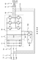
図4には、ジェネレータ(10)をエネルギー蓄積部(90)から給電してモータとして稼動する可能性を有する図1による回路装置が示されている。そのために、コイル(901)と、ダイオード(902)と、スイッチ(903)とから成る昇圧変換器(900)が中間回路(41)に接続されている。始動段階中、インバータ(30)の出力部はスイッチ(92)を用いて電力供給網から切り離されている。更に、インバータ(30)の出力部をスイッチ(93)を用いてジェネレータ(モータ)(10)と接続すること、並びに、ジェネレータ(10)をスイッチ(94)を用いてブリッジ整流器(21)の入力部から切り離すことが必要である。
【0024】
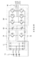
図5には、本発明による回路装置の構成が示されていて、ここでは、ジェネレータとして永久励磁式3相ジェネレータが使用され、このジェネレータは、その回転数に依存して、変化する周波数を有する変化する電圧を生成する。永久励磁式ジェネレータは、それらが簡単に構成されていて、全ての稼動状態、即ち様々な回転数において極めて高い効率を達成するという長所を有する。回転数に対する出力電圧の依存性は以下の式で表される:
【0025】
【数1】
Ugeni=k・Φ・n
【0026】
ここで、nは回転数、kは定数、Φはジェネレータ内の磁束、iは1…3である。
【0027】
ジェネレータ巻線は星型結線で接続されていて、中性線Nが同様に導き出されている。
【0028】
電圧Ugen1、Ugen2、Ugen3は、3つのインダクタ(インダクタンスコイル、111〜113)を介してジェネレータ側のインバータ(20)と接続されていて、この際、それらのインダクタ(111〜113)はジェネレータ(10)の内部インダクタであり得る。これらのインダクタが各々のジェネレータにおいて小さすぎるものと示される場合には、追加的に外部のチョークが使用される。インバータ(20)の方は、パワースイッチとしてのIGBT(211〜216)及びそれらに各々逆並列接続されているフリーホイールダイオード(201〜206)を有する3相ブリッジ装置から構成されている。
【0029】
中間回路(40)は、直列に接続されている2つのコンデンサ(410、420)又は対応的なコンデンサグループによって形成される。この直列回路の中心点は中性線Nと接続されている。
【0030】
中間回路(40)の後には供給網側のインバータ(30)が接続されていて、このインバータ(30)の方は、相(トポロジー)的にジェネレータ側のものと同一であり、それにより、同様に、逆並列接続されているフライホイールダイオード(301〜306)を有するIGBT(311〜316)から構成されている。各相(R、S、T)のための3つの出力部の後には3つのチョーク(チョークコイル、50)が接続されている。
【0031】
発電機の始動を電力供給網からの供給を伴わなくても可能とするために、エネルギー蓄積部(90)が次のように接続されている。即ち、2つのスイッチグループを用い、供給網側のインバータ(30)の出力部(R、S、T)がスイッチグループ(92)を介して電力供給網と接続されているか、又は、供給網側のインバータ(30)の出力部(S、T)がスイッチグループ(91)を介してエネルギー蓄積部(90)と接続されているようにである。エネルギー蓄積部の破壊を防止するために、常に両方のスイッチグループ(91、92)の1つだけが閉じられていることが可能である。
【0032】
回路装置のためには、後に説明する以下の稼動状態が可能である:
1.電力供給網から給電されるスタータ稼動
2.エネルギー蓄積部から給電されるスタータ稼動
3.供給網電圧と比べてほぼファクタ1.4だけ大きい出力電圧を有する発電機稼動
4.供給網電圧のほぼ1.4倍よりも小さいジェネレータの出力電圧を有する発電機稼動
【0033】
1.電力供給網から給電されるスタータ稼動について:
スイッチグループ(92)のスイッチは閉じている。供給網電流の3相は、供給網側のインバータ(30)のダイオード(301〜306)を介して中間回路コンデンサ(410、420)を充電する。パワースイッチ(311〜316)の適切なスイッチングにより、中間回路電圧は所望値に維持される。ジェネレータ側のインバータ(20)は、ジェネレータ(10)がモータとして稼動されるように駆動される。この際、モータは、発電機の実際の駆動部、例えばバイオガスモータ又はガスタービンを動かす。この駆動部が始動された後、回路装置は発電機稼動(以下の3項及び4項を参照)で稼動される。
【0034】
2.エネルギー蓄積部から給電されるスタータ稼動について:
始動プロセスのためのエネルギー源として、エネルギー蓄積部、例えばアキュムレータが使用される。スイッチグループ(92)のスイッチは開いていて、それに対してスイッチグループ(91)のスイッチは閉じている。この際、電流はエネルギー蓄積部から供給網側のインバータ(30)内に流れる。パワースイッチ(312、314)は、パルス稼動において、以下の式が満たされているように駆動される:
【0035】
【数2】
UZW=Ubatt・Tein/(T−Tein)
【0036】
ここで、Tはスイッチングの周期、Teinはスイッチオン期間、UZWは中間回路の電圧(目標)、Ubattはエネルギー蓄積部の電圧である。
【0037】
時間空間Teinのために、エネルギー蓄積部(90)は、チョーク(503)、パワースイッチ(312)、ダイオード(304)、チョーク(502)を介して短絡されている。この際、バッテリからの電流の流れは、チョーク(502及び503)のインダクタンスに依存して増加する。パワースイッチ(312)のスイッチオフ後、電流はダイオード(301、304)を介して中間回路内に流れる。ここで供給網側のインバータ(30)は、中間回路(40)を充電するために昇圧変換器として使用される。それに対し、ジェネレータ側のインバータ(20)は、ジェネレータ(10)がモータとして稼動されるように駆動される。この際、モータは発電機の実際の駆動部を動かす。駆動部が始動された後、スイッチグループ(91)のスイッチは開かれ、スイッチグループ(92)のスイッチが閉じられ、回路装置が発電機稼動で稼動される。
【0038】
3.供給網電圧と比べてほぼファクタ1.4だけ大きい出力電圧を有する発電機稼動について:
この場合、ジェネレータ(10)は次のような電圧を生成する。即ち、整流の後にジェネレータ側のインバータ(20)のダイオード(201〜206)により中間回路(40)を次のように充電するために十分な電圧である。即ち、供給網側のインバータ(30)により生成される3相交流電圧が電力供給網内に電流を供給するために十分に大きいようにである。
【0039】
4.供給網電圧のほぼ1.4倍よりも小さいジェネレータの出力電圧を有する発電機稼動について:
この稼動状態では、中間回路(40)内で必要な電圧を維持するために、ジェネレータ(10)により生成される電圧が昇圧変換器を用いて高められる。このために、それぞれのジェネレータ出力電圧に対し、インダクタ並びにそれに割り当てられているジェネレータ側のインバータのハーフブリッジが使用される。電圧Ugen1のためには、インダクタ(111)、パワースイッチ(211、212)並びにダイオード(201、202)が使用され、電圧Ugen2と電圧Ugen3のためには、対応して、インダクタ(112或いは113)、パワースイッチ(213、214或いは215、216)及びダイオード(203、204或いは205、206)が使用される。
【0040】
例として、位相Ugen1を詳細に説明する。中間回路の目標電圧の1/2よりも小さい電圧がコンデンサ(410)に印加される場合、Ugen1が正の半波である間、パワースイッチ(212)がスイッチオンされる。それにより、インダクタ(111)、パワースイッチ(212)及びコンデンサ(420)を介してUgen1の短絡が発生する。パワースイッチ(212)のスイッチオフ後、コンデンサ(410)は、電圧Ugen1により、インダクタ(111)内に蓄積されたエネルギーにより、ダイオード(201)を介して充電される。この際、インダクタ(111)内にエネルギーが蓄積されていることが利用される。負の半波の場合には、コンデンサ(410)は、対応する方式で、パワースイッチ(211)及びダイオード(202)を介して充電される。従って、2つの昇圧変換器の作用方式が得られる。
【0041】
他の両方の位相Ugen2及びUgen3は、対応する方式で、中間回路(40)を充電するために寄与する。説明した昇圧変換器の作用方式により、中間回路(40)内の電圧は、電圧の半分が各々コンデンサ(410)或いはコンデンサ(420)上に割り当てられるように制御される。両方のコンデンサ間の中心点に中性線が接続されているので、中性線の電位は、常に確実に中間回路電圧の中間に位置する。
【0042】
このことは、ジェネレータの出力電圧が僅かな場合でも必要な中間回路電圧が印加するという長所を有するばかりか、供給網側のインバータの出力相(R、S、T)の負荷が非対称の場合にも相電圧の変動が生じないという長所を有する。
【0043】
本発明による回路装置の上記の機能方式に基づき、この回路装置は、回路技術的な変更を伴うことなく、様々な電圧と周波数、例えば、380V、400V、440V、480V、又は500V、及び、50Hz又は60Hzを有する電力供給網に適合され得る。
【図面の簡単な説明】
【図1】従来技術による回路装置であって、変圧器を使用してジェネレータから電力供給網内にエネルギーを流すための、中性線を伴わない回路装置を示す図である。
【図2】従来技術による回路装置であって、昇圧変換器を使用してジェネレータから電力供給網内にエネルギーを流すための、中性線電位が能動生成される回路装置を示す図である。
【図3】従来技術による回路装置であって、2つの昇圧変換器を使用してジェネレータから電力供給網内にエネルギーを流すための、中性線の電位が能動制御される回路装置を示す図である。
【図4】従来技術による回路装置であって、ジェネレータをエネルギー蓄積部から給電してモータとして可動する可能性を有する図1による回路装置を示す図である。
【図5】本発明による回路装置の構成を示す図であり、この回路装置は、図2から図4による回路装置の全ての機能方式を提供する。
【符号の説明】
10 ジェネレータ
111〜113 インダクタ(インダクタンスコイル)
20 インバータ
21 ブリッジ整流器
201〜206 フリーホイールダイオード
211〜216 パワースイッチ(IGBT)
30 インバータ
301〜306 フリーホイールダイオード
311〜316 パワースイッチ(IGBT)
40、41 中間回路
410、420 コンデンサ
50 チョーク(チョークコイル)
501〜503 チョーク(チョークコイル)
60 変圧器
70 昇圧変換器
71 コイル
72 ダイオード
73 スイッチ
74、75 昇圧器
80 ハーフブリッジ回路
90 エネルギー蓄積部
91〜94 スイッチ(スイッチグループ)
900 昇圧変換器
901 コイル
902 ダイオード
903 スイッチ[0001]
BACKGROUND OF THE INVENTION
The present invention relates to a circuit device for generating a three-phase alternating current using a low-power (10 kVA to 5 MVA) generator to feed power into a power supply network. Low-power generators, including those with power, heat, and connections, are distributed energy supply units, as emergency current aggregates, and distributed aggregates to equalize demand peaks in the power supply network It is particularly suitable for a power supply unit in a predetermined area as a body or without access to a public power supply network.
[0002]
[Prior art]
Such low or medium power generators are driven by, for example, gas turbines, fuel cells with integrated gas turbines, biogas motors or diesel motors. The advantage of these generators is the variable output of their power. These generators are adjusted depending on the actual demand by adjusting the generator drive to their power. Thereby, only the amount of energy required to generate electrical energy is consumed.
[0003]
A wind power generator is likewise a generator with variable power output. In this case, a controllable value, such as a set angle of the rotor blade, and an uncontrollable value, such as wind speed, form the output power parameter.
[0004]
However, in this case, there is a disadvantage that the power generated by the generator does not normally correspond to that required by the power supply network on the output side at the voltage and the frequency. This is especially a problem when control depends on demand. Many of the drives for low power generators operate at relatively high speeds, thereby generating frequencies in the kilohertz range for generators that are arranged without a transmission. On the other hand, there is a demand for a 50 Hz or 60 Hz power supply network. Particularly economically and dynamically adapting to different requirements produces a voltage that varies in the output current in the case of a permanently excited synchronous generator. For other excitation synchronous generator types, the voltage can be adapted via the generator excitation current, but this reduces the efficiency of the generator. Various power electronics circuit devices are known, but these circuit devices, as converters, pose problems relating to the matching of electrical values.
[0005]
Furthermore, it may be necessary to start the generator with energy from the power supply network or, if there is no power supply network, with energy from an external energy store. It is meaningful to charge the energy storage unit continuously.
[0006]
[Patent Document 1]
From US 6020713 a circuit arrangement for a permanent excitation generator or other excitation generator is known, in which the generator output voltage is converted into an intermediate circuit DC voltage using two diode rectifiers. Is done. An output voltage is generated from the intermediate circuit DC voltage using an output / inverter, and this output voltage is adapted to a voltage required by the power supply network via a transformer. Thereby, a three-phase output voltage having 380V, 400V, 440V, 480V, or 500V and 50Hz or 60Hz can be generated. Similarly, neutral lines must be provided for the three-phase supply network. The disadvantage of this circuit arrangement is that a transformer that is sized for maximum output power is required on the output side, which is because the transformer makes the generator expensive, This is to increase the space requirement.
[0007]
This circuit arrangement according to US Pat. No. 6,060,713 can be used in the same way without a transformer in the output, but in this case the maximum value of the output voltage is limited by the generator voltage . In this case, the circuit device described above has the disadvantage that the starting process of the generator is not possible using simple means.
[0008]
Similarly, U.S. Pat. No. 6,020,713 introduces a circuit arrangement having a fourth half bridge to actively control a neutral wire, which also has the disadvantages described above.
[0009]
[Patent Document 2]
US Pat. No. 6020713 and US Pat. No. 6,993,975 likewise introduce a circuit arrangement that uses this generator as a starter for a gas turbine that drives the generator when the generator is in operation. For this purpose, the auxiliary rectifier is connected to the power supply network using a switch group, and at the same time, the generator is connected to the output part of the inverter via the switch group, and the output part of the inverter is connected via another switch group. Separated from the power supply network. This auxiliary rectifier feeds the intermediate circuit from the power supply network. The subsequently assigned inverter drives a generator, which operates as a motor and starts the gas turbine. In US Pat. No. 6,993,975, an auxiliary circuit arrangement is provided whereby energy for starting the gas turbine is taken from an energy storage, for example a battery. Therefore, the battery voltage is increased by using an external boost converter (boost converter), thereby charging the intermediate circuit. Thereby, a generator connected after the inverter can start the gas turbine using the battery.
[0010]
In both of these circuit arrangements, the solution using an external transformer has this known disadvantage, and the solution without this transformer has a maximum output voltage directly. The disadvantage is that it is connected to the generator voltage. Furthermore, the disadvantage is that three mechanical switch groups are required for the start-up process, or other auxiliary circuits need to be provided for start-up using batteries.
[0011]
[Problems to be solved by the invention]
It is an object of the present invention to provide a circuit device using as few elements as possible, which circuit device drives a generator driven by a machine or a windmill and rotated at a variable rotational speed at three-
[0012]
[Means for Solving the Problems]
This object is achieved according to the invention by a circuit arrangement according to claim 1, with advantageous configurations in the dependent claims.
[0013]
The circuit arrangement according to the invention consists of a symmetrical arrangement of two three-phase inverters, an intermediate circuit consisting of capacitor groups connected in series, an inductor placed after the generator, and a neutral wire, this neutral The wires are connected on the one hand to the star connections of the generator windings assigned to the three phases and on the other hand to the center points of the capacitor groups connected in series.
[0014]
During normal operation of the circuit device, when energy flows from the generator to the power supply network, and after rectification to generate an intermediate circuit voltage, the power supply network is directly connected using an inverter connected thereafter. When the generator voltage is high enough to supply power, the generator flywheel diode functions as a diode, input, and rectifier. This diode / input / rectifier generates an intermediate circuit DC voltage from the AC voltage of the generator, and this intermediate circuit DC voltage is converted into a desired supply network voltage having a corresponding supply network frequency in an inverter on the supply network side. And supplied directly to the power supply network via the choke, that is, without using a transformer.
[0015]
If the generator voltage is too low in accordance with the above definition, for example due to the same energy flow, eg due to low energy requirements and at the same time low generator speed, the generator-side inverter is boost converted with the generator-side choke. It functions as a vessel. Therefore, the intermediate circuit is charged to the required voltage, and the inverter on the supply network side converts this DC voltage into a desired supply network voltage having a corresponding supply network frequency, and this converted voltage further Directly supplied to the power supply network via the choke.
[0016]
The same applies when the starter is operating, i.e., when a current flows through the generator, and this current flow causes the generator to operate as a motor and thereby the generator is used to start an actual drive (e.g., a gas turbine). Two cases are distinguished.
[0017]
When the starter is fed from the power supply network, the freewheel diode of the inverter on the supply network functions as a diode / input bridge. This diode input bridge generates an intermediate circuit DC voltage from the supply network voltage. This intermediate circuit DC voltage is converted by an inverter on the generator side in order to drive a generator that currently operates as a motor.
[0018]
If no voltage is provided from the power supply network for startup, the energy storage is connected to the circuit device as follows. That is, the inverter on the supply network side is disconnected from the power supply network using a switch group, and the energy storage unit is connected to two or three output units of the inverter on the supply network side using another switch group. It is. When the starter is operated by supplying power from the energy storage unit, the inverter on the supply network side is disconnected from the power supply network and connected to the energy storage unit. Since a typical energy storage unit has a smaller voltage than is necessary to run the generator as a motor, the inverter on the supply network side functions as a boost converter with the choke on the supply network side, thereby generating the generator Generates the required voltage in the intermediate circuit so that it can be operated as a starter motor using an inverter on the generator side.
[0019]
DETAILED DESCRIPTION OF THE INVENTION
Next, a specific form of the idea of the present invention will be described in detail with reference to FIGS.
[0020]
FIG. 1 shows a prior art circuit arrangement for flowing energy from a generator into a power supply network using a transformer, in which no neutral wire is used. Here, the three phases of the generator (10) are rectified using the bridge rectifier (21), and intermediately stored in the capacitor in the intermediate circuit (41). From this DC voltage, the inverter (30) generates a sinusoidal AC voltage. A transformer (60) is essential to adapt the voltage to the supply network. In this circuit design, it is possible to compensate for the variable number of revolutions of the generator and the variable output voltage of the generator, but this compensation is extremely inadequate. This type of circuit device is very well suited for generators driven at a constant rotational speed.
[0021]
FIG. 2 shows a prior art circuit device for flowing energy from a generator into a power supply network using a boost converter (boost converter), where the neutral line potential (N) is shown. Are actively generated. Here, for the circuit arrangement according to FIG. 1, the adaptation of the output voltage is not carried out using a transformer, but the voltage is already intermediated using a boost converter (70), following the bridge rectifier (21). To the circuit voltage is increased to the required value of the intermediate circuit voltage. Here, the step-up converter (70) includes a coil (71), a diode (72), and a switch (73), here, an IGBT having a diode connected in antiparallel. The voltage in the intermediate circuit (41) is adjusted to a desired output voltage (supply network voltage) of the inverter (30) by a known method. The output part of the inverter (30) is connected to the power supply network through a choke (50). The supply network neutral line (N) is actively enabled by another half-bridge circuit (80).
[0022]
FIG. 3 shows a prior art circuit device for flowing energy from a generator into a power supply network using two boost converters, in which the neutral line potential is actively controlled. The The voltage increase already described with reference to FIG. 2 is performed here using two boost converters (74, 75). The generated intermediate circuit voltage is accumulated in the capacitors (410, 420) of the intermediate circuit (40) connected in series. These flexible boost converters (74, 75) allow the elimination of an additional half-bridge circuit (80) for active control of the neutral line potential. For this purpose, the supply network neutral line is connected to the central point of the series circuit of the intermediate circuit capacitors (410, 420) and the generator (10).
[0023]
FIG. 4 shows the circuit arrangement according to FIG. 1 with the possibility of operating the generator (10) from the energy storage (90) as a motor. For this purpose, a boost converter (900) including a coil (901), a diode (902), and a switch (903) is connected to the intermediate circuit (41). During the start-up phase, the output of the inverter (30) is disconnected from the power supply network using the switch (92). Further, the output of the inverter (30) is connected to the generator (motor) (10) using the switch (93), and the generator (10) is connected to the input of the bridge rectifier (21) using the switch (94). It is necessary to separate from the part.
[0024]
FIG. 5 shows the configuration of a circuit arrangement according to the invention, in which a permanently excited three-phase generator is used as the generator, which has a frequency that varies depending on its rotational speed. Generate a changing voltage. Permanently excited generators have the advantage that they are simple to construct and achieve very high efficiency in all operating states, i.e. at various speeds. The dependence of the output voltage on the rotational speed is expressed by the following formula:
[0025]
[Expression 1]
U gen i = k ・ Φ ・ n
[0026]
Here, n is the number of revolutions, k is a constant, Φ is the magnetic flux in the generator, and i is 1.
[0027]
The generator windings are connected by a star connection, and a neutral wire N is similarly derived.
[0028]
The voltages U gen 1, U gen 2, and U gen 3 are connected to the generator-side inverter (20) via three inductors (inductance coils, 111 to 113). 113) may be an internal inductor of the generator (10). If these inductors are shown to be too small in each generator, additional external chokes are used. The inverter (20) is made up of a three-phase bridge device having IGBTs (211 to 216) as power switches and freewheeling diodes (201 to 206) connected in antiparallel to them.
[0029]
The intermediate circuit (40) is formed by two capacitors (410, 420) connected in series or a corresponding capacitor group. The center point of this series circuit is connected to the neutral line N.
[0030]
An inverter (30) on the supply network side is connected after the intermediate circuit (40), and this inverter (30) is identical in phase (topology) to that on the generator side. And IGBTs (311 to 316) having flywheel diodes (301 to 306) connected in reverse parallel. Three chokes (choke coils 50) are connected after the three outputs for each phase (R, S, T).
[0031]
In order to enable the generator to be started without being supplied from the power supply network, the energy storage unit (90) is connected as follows. That is, two switch groups are used, and the output unit (R, S, T) of the inverter (30) on the supply network side is connected to the power supply network via the switch group (92), or the supply network side It seems that the output unit (S, T) of the inverter (30) is connected to the energy storage unit (90) via the switch group (91). Only one of both switch groups (91, 92) can be closed at any time in order to prevent destruction of the energy storage.
[0032]
For the circuit arrangement, the following operating states described below are possible:
1. 1. Starter operation powered by the power supply network 2. Starter operation powered by the energy storage unit 3. Generator operation with an output voltage approximately 1.4 greater than the supply network voltage. Generator operation with generator output voltage less than about 1.4 times the supply network voltage
1. About starter operation fed from the power supply network:
The switches of the switch group (92) are closed. The three phases of the supply network current charge the intermediate circuit capacitors (410, 420) via the diodes (301 to 306) of the inverter (30) on the supply network side. By appropriate switching of the power switches (311 to 316), the intermediate circuit voltage is maintained at a desired value. The generator-side inverter (20) is driven so that the generator (10) is operated as a motor. In this case, the motor drives the actual drive of the generator, for example a biogas motor or a gas turbine. After the drive is started, the circuit device is operated with the generator running (see paragraphs 3 and 4 below).
[0034]
2. About starter operation powered by energy storage:
An energy storage, such as an accumulator, is used as an energy source for the starting process. The switches in switch group (92) are open, while the switches in switch group (91) are closed. At this time, current flows from the energy storage unit into the inverter (30) on the supply network side. The power switches (312, 314) are driven in pulse operation so that the following equation is satisfied:
[0035]
[Expression 2]
U ZW = U batt · T ein / (T−T ein )
[0036]
Here, T is a switching cycle, T ein is a switch-on period, U ZW is a voltage (target) of the intermediate circuit, and U batt is a voltage of the energy storage unit.
[0037]
Due to the time space Tein , the energy storage unit (90) is short-circuited via the choke (503), the power switch (312), the diode (304), and the choke (502). At this time, the current flow from the battery increases depending on the inductance of the chokes (502 and 503). After the power switch (312) is switched off, current flows in the intermediate circuit via the diodes (301, 304). Here, the inverter (30) on the supply network side is used as a step-up converter for charging the intermediate circuit (40). On the other hand, the inverter (20) on the generator side is driven so that the generator (10) is operated as a motor. At this time, the motor moves the actual drive of the generator. After the drive unit is started, the switches of the switch group (91) are opened, the switches of the switch group (92) are closed, and the circuit device is operated by operating the generator.
[0038]
3. For generator operation with an output voltage approximately 1.4 greater than the supply network voltage:
In this case, the generator (10) generates the following voltage. That is, the voltage is sufficient to charge the intermediate circuit (40) as follows by the diodes (201 to 206) of the inverter (20) on the generator side after rectification. That is, the three-phase AC voltage generated by the inverter (30) on the supply network side is sufficiently large to supply current into the power supply network.
[0039]
4). For generator operation with generator output voltage less than approximately 1.4 times the supply network voltage:
In this operating state, the voltage generated by the generator (10) is increased using a boost converter in order to maintain the necessary voltage in the intermediate circuit (40). For this purpose, for each generator output voltage, an inductor and a generator-side inverter half bridge assigned to it are used. For voltage U gen 1, inductor (111), power switches (211, 212) and diodes (201, 202) are used, and for voltage U gen 2 and voltage U gen 3, correspondingly, An inductor (112 or 113), a power switch (213, 214 or 215, 216) and a diode (203, 204 or 205, 206) are used.
[0040]
As an example, phase U gen 1 will be described in detail. When a voltage less than 1/2 of the target voltage of the intermediate circuit is applied to the capacitor (410), the power switch (212) is switched on while U gen 1 is a positive half wave. This causes a short circuit of U gen 1 via the inductor (111), the power switch (212), and the capacitor (420). After the power switch (212) is switched off, the capacitor (410) is charged via the diode (201) with the energy stored in the inductor (111) by the voltage U gen 1. At this time, it is utilized that energy is stored in the inductor (111). In the case of a negative half wave, the capacitor (410) is charged via the power switch (211) and the diode (202) in a corresponding manner. Therefore, the operation system of two boost converters can be obtained.
[0041]
Both other phases U gen 2 and U gen 3 contribute to charge the intermediate circuit (40) in a corresponding manner. With the described step-up converter mode of operation, the voltage in the intermediate circuit (40) is controlled such that half of the voltage is allocated on the capacitor (410) or capacitor (420), respectively. Since the neutral wire is connected to the center point between both capacitors, the potential of the neutral wire is always reliably located in the middle of the intermediate circuit voltage.
[0042]
This not only has the advantage that the necessary intermediate circuit voltage is applied even when the output voltage of the generator is small, but also when the load on the output phase (R, S, T) of the inverter on the supply network side is asymmetric. However, there is an advantage that the phase voltage does not fluctuate.
[0043]
Based on the above functional scheme of the circuit device according to the present invention, this circuit device has various voltages and frequencies, for example 380 V, 400 V, 440 V, 480 V or 500 V and 50 Hz, without any change in circuit technology. Or it can be adapted to a power supply network having 60 Hz.
[Brief description of the drawings]
FIG. 1 shows a circuit device according to the prior art, without a neutral line, for flowing energy from a generator into a power supply network using a transformer.
FIG. 2 is a diagram showing a circuit device according to the prior art in which a neutral line potential is actively generated to flow energy from a generator into a power supply network using a boost converter.
FIG. 3 shows a circuit device according to the prior art, in which the potential of the neutral line is actively controlled to flow energy from the generator into the power supply network using two boost converters. It is.
4 shows a circuit device according to FIG. 1, which is a circuit device according to the prior art, and has the possibility of moving a generator as a motor by feeding power from an energy storage unit.
FIG. 5 is a diagram showing the configuration of a circuit device according to the present invention, which provides all functional schemes of the circuit device according to FIGS.
[Explanation of symbols]
10 Generator 111-113 Inductor (Inductance coil)
20
30
40, 41
501 to 503 Choke (Choke coil)
60
900
Claims (5)
Applications Claiming Priority (2)
| Application Number | Priority Date | Filing Date | Title |
|---|---|---|---|
| DE10156694A DE10156694B4 (en) | 2001-11-17 | 2001-11-17 | circuitry |
| DE10156694.8 | 2001-11-17 |
Publications (3)
| Publication Number | Publication Date |
|---|---|
| JP2003164165A JP2003164165A (en) | 2003-06-06 |
| JP2003164165A5 JP2003164165A5 (en) | 2005-10-27 |
| JP4221207B2 true JP4221207B2 (en) | 2009-02-12 |
Family
ID=7706209
Family Applications (1)
| Application Number | Title | Priority Date | Filing Date |
|---|---|---|---|
| JP2002325441A Expired - Fee Related JP4221207B2 (en) | 2001-11-17 | 2002-11-08 | Circuit equipment |
Country Status (7)
| Country | Link |
|---|---|
| US (1) | US6750633B2 (en) |
| EP (1) | EP1313206B1 (en) |
| JP (1) | JP4221207B2 (en) |
| AT (1) | ATE272912T1 (en) |
| DE (2) | DE10156694B4 (en) |
| DK (1) | DK1313206T3 (en) |
| ES (1) | ES2225715T3 (en) |
Cited By (2)
| Publication number | Priority date | Publication date | Assignee | Title |
|---|---|---|---|---|
| US9592705B2 (en) | 2011-04-28 | 2017-03-14 | Compagnie Generale Des Etablissements Michelin | Pneumatic tire |
| US9770952B2 (en) | 2011-12-05 | 2017-09-26 | Compagnie Generale Des Etablissements Michelin | Noise-reducing device for a tire |
Families Citing this family (63)
| Publication number | Priority date | Publication date | Assignee | Title |
|---|---|---|---|---|
| SE0001611L (en) * | 2000-05-03 | 2001-11-04 | Abb Ab | Power plant and method of operation thereof |
| DE10103520A1 (en) * | 2001-01-26 | 2002-08-01 | Isad Electronic Sys Gmbh & Co | Generator system, in particular for a motor vehicle, and method for controlling an inverter of an asynchronous generator |
| US7015595B2 (en) * | 2002-02-11 | 2006-03-21 | Vestas Wind Systems A/S | Variable speed wind turbine having a passive grid side rectifier with scalar power control and dependent pitch control |
| US6933704B2 (en) * | 2002-10-11 | 2005-08-23 | Siemens Westinghouse Power Corporation | Slip-inducing rotation starting exciter for turbine generator |
| US20040085046A1 (en) * | 2002-11-01 | 2004-05-06 | General Electric Company | Power conditioning system for turbine motor/generator |
| EP1467094B2 (en) * | 2003-04-08 | 2017-03-01 | GE Energy Power Conversion GmbH | A wind turbine for producing electrical power and a method of operating the same |
| US7042110B2 (en) * | 2003-05-07 | 2006-05-09 | Clipper Windpower Technology, Inc. | Variable speed distributed drive train wind turbine system |
| DE10330473A1 (en) * | 2003-07-05 | 2005-01-27 | Alstom Technology Ltd | Frequency converter for high-speed generators |
| EP1501180A1 (en) * | 2003-07-23 | 2005-01-26 | ABB Schweiz AG | Converter circuit |
| JP2005042684A (en) * | 2003-07-25 | 2005-02-17 | Denso Corp | Power control device for turbo charger with electric motor and motor-driven turbo charger device |
| KR100654487B1 (en) * | 2003-09-09 | 2006-12-05 | 마츠시타 덴끼 산교 가부시키가이샤 | Converter circuit, motor driving device, compressor, air conditioner, refrigerator, electric washing machine, fan, electric cleaner, and heat pump water-warmer |
| US7088601B2 (en) * | 2004-01-23 | 2006-08-08 | Eaton Power Quality Corporation | Power conversion apparatus and methods using DC bus shifting |
| DE102004003657B4 (en) * | 2004-01-24 | 2012-08-23 | Semikron Elektronik Gmbh & Co. Kg | Converter circuit arrangement and associated drive method for dynamically variable output generators |
| JP4339757B2 (en) * | 2004-07-12 | 2009-10-07 | 株式会社日立製作所 | Vehicle drive power generation system |
| US7429855B2 (en) * | 2004-09-20 | 2008-09-30 | Hamilton Sundstrand Corporation | Regenerative load bank with a motor drive |
| FR2875970B1 (en) * | 2004-09-27 | 2008-01-18 | Schneider Electric Ind Sas | DEVICE AND METHOD FOR CONTROLLING AN ELECTRIC POWER CONVERTER AND CONVERTER COMPRISING SUCH A DEVICE |
| EP1844539B1 (en) * | 2005-01-28 | 2019-09-11 | Signify Holding B.V. | Method and inverter for converting a dc voltage into a 3-phase ac output |
| US7932693B2 (en) * | 2005-07-07 | 2011-04-26 | Eaton Corporation | System and method of controlling power to a non-motor load |
| US7239036B2 (en) * | 2005-07-29 | 2007-07-03 | General Electric Company | System and method for power control in wind turbines |
| KR100729852B1 (en) | 2005-12-14 | 2007-06-18 | 한국전기연구원 | Control system with three-phase and four-wire type converter for doubly-fed induction generator |
| DK1852605T3 (en) | 2005-12-15 | 2016-08-29 | Osterholz Heinz-Günter | Angular control of wind turbine blades in a wind turbine in an emergency |
| KR100668118B1 (en) * | 2005-12-30 | 2007-01-16 | 한국전기연구원 | A electrical power converter and power converting method for doubly-fed induction generator |
| US7423894B2 (en) * | 2006-03-03 | 2008-09-09 | Advanced Energy Industries, Inc. | Interleaved soft switching bridge power converter |
| DE102006020144B4 (en) * | 2006-05-02 | 2008-06-26 | Siemens Ag | Method for operating a marine propulsion system with waste heat recovery and marine propulsion system with waste heat recovery |
| US7649756B2 (en) * | 2006-05-17 | 2010-01-19 | Rockwell Automation Technologies, Inc. | Common mode noise reduction in converter systems through modification of single phase switching signal |
| DE102006028103A1 (en) * | 2006-06-19 | 2007-12-20 | Siemens Ag | Line-side converter with uninterrupted switching between pulsed voltage-controlled operation and fundamental frequency unregulated operation, as well as method for uninterrupted switching of such a converter |
| US7514809B2 (en) * | 2006-11-16 | 2009-04-07 | General Electric Company | Excitation voltage supply for synchronous generator used in a wind turbine, and method of starting a wind turbine having such excitation voltage supply |
| CA2673298C (en) * | 2006-12-20 | 2016-05-17 | Analogic Corporation | Non-contact rotary power transfer system |
| DE102006062406A1 (en) * | 2006-12-21 | 2008-06-26 | Prettl, Rolf | Converter circuit for the exchange of electrical power quantities, method for driving a converter circuit and power generator |
| PL1959554T3 (en) | 2007-02-14 | 2010-11-30 | Semikron Elektronik Gmbh & Co Kg | Converter circuit for a doubly-fed asynchronous generator with variable output power and method for its operation |
| US7728562B2 (en) * | 2007-07-27 | 2010-06-01 | Gm Global Technology Operations, Inc. | Voltage link control of a DC-AC boost converter system |
| JP4238935B1 (en) * | 2007-08-28 | 2009-03-18 | ダイキン工業株式会社 | Direct AC power converter |
| JP4483911B2 (en) | 2007-08-31 | 2010-06-16 | 株式会社デンソー | Rotating electric machine for vehicles |
| ITBO20070600A1 (en) * | 2007-09-03 | 2009-03-04 | Energifera S R L | SYSTEM FOR CONTEMPORARY PRODUCTION OF ELECTRICITY AND THERMAL ENERGY |
| JP4506848B2 (en) * | 2008-02-08 | 2010-07-21 | 株式会社デンソー | Semiconductor module |
| DE102008049310A1 (en) * | 2008-09-29 | 2010-03-04 | Kenersys Gmbh | Wind energy plant for production of electricity, has rectifier, intermediate circuit and inverter for conversion of three phase alternating current of primary frequency, into three phase alternating current of secondary frequency |
| DE102008042693B4 (en) * | 2008-10-08 | 2015-10-08 | Semikron Elektronik Gmbh & Co. Kg | Method for operating a power converter circuit with voltage increase |
| DE102008059330A1 (en) * | 2008-11-27 | 2010-06-02 | Siemens Aktiengesellschaft | Three-phase power inverter for e.g. solar module, has four-point half bridge module including half bridge that performs circuit design based function of free-wheeling diode and switching element of step-up chopper unit |
| EP2244383A1 (en) * | 2009-04-23 | 2010-10-27 | Mitsubishi Electric R&D Centre Europe B.V. | Method and apparatus for controlling the operation of a snubber circuit |
| DE102009022492A1 (en) | 2009-05-25 | 2010-12-02 | Sensaction Ag | Device for determining the properties of a medium in the form of a liquid or a soft material |
| DE102009054971A1 (en) * | 2009-12-18 | 2011-06-22 | LTi DRiVES GmbH, 35633 | Circuit for current generator i.e. emergency power generator, in e.g. hospital, has converter converting voltage potential of generator-direct current voltage circuit into voltage potential of power line-direct current voltage circuit |
| US8378641B2 (en) * | 2010-07-12 | 2013-02-19 | Hamilton Sundstrand Corporation | Electric power generating system with boost converter/synchronous active filter |
| DE102011004733A1 (en) * | 2011-02-25 | 2012-08-30 | Siemens Aktiengesellschaft | Submodule of a modular multistage converter |
| JP2012231567A (en) * | 2011-04-25 | 2012-11-22 | Yamabiko Corp | Three-phase inverter type power generator |
| CA2836984C (en) * | 2011-06-08 | 2018-08-07 | L-3 Communications Magnet-Motor Gmbh | Method of controlling a dc/ac converter |
| EP2719068B1 (en) * | 2011-06-08 | 2020-08-12 | L-3 Communications Magnet-Motor GmbH | Dc/ac converter and method of controlling a dc/ac converter |
| WO2013185847A1 (en) * | 2012-06-15 | 2013-12-19 | Huawei Technologies Co., Ltd. | Method and apparatus for performing power conversion |
| CN102761269B (en) * | 2012-06-30 | 2015-11-25 | 华为技术有限公司 | Frequency converter |
| US9246411B2 (en) * | 2012-10-16 | 2016-01-26 | Rockwell Automation Technologies, Inc. | Regenerative voltage doubler rectifier, voltage sag/swell correction apparatus and operating methods |
| US8941961B2 (en) | 2013-03-14 | 2015-01-27 | Boulder Wind Power, Inc. | Methods and apparatus for protection in a multi-phase machine |
| US8853876B1 (en) * | 2013-04-26 | 2014-10-07 | General Electric Company | Switching-based control for a power converter |
| DE102013218631A1 (en) * | 2013-09-17 | 2015-03-19 | Siemens Aktiengesellschaft | System comprising a turbine and a mechanically coupled electric machine and method of operating such a system |
| CN105850025B (en) | 2013-12-26 | 2018-02-09 | 三菱电机株式会社 | Power-converting device |
| CN104079182B (en) * | 2014-06-18 | 2017-11-21 | 华为技术有限公司 | Inverter system |
| CN105471393B (en) * | 2014-09-12 | 2018-12-18 | 通用电气公司 | The switching amplifier operated with zero voltage switch and thermal equilibrium control algorithm |
| US9997917B2 (en) | 2015-07-01 | 2018-06-12 | Google Llc | Transformerless power conversion |
| CN106921299A (en) * | 2015-12-25 | 2017-07-04 | 通用电气公司 | Power conversion system |
| DE102016202102A1 (en) | 2016-02-11 | 2017-08-17 | Volkswagen Aktiengesellschaft | Multifunctional and highly integrated power converter component |
| CN106532777A (en) * | 2016-12-30 | 2017-03-22 | 量子光电科技(天津)有限公司 | Novel high-voltage DC wind power generator set and group network |
| JP6828516B2 (en) * | 2017-03-02 | 2021-02-10 | ダイキン工業株式会社 | Power converter |
| CN108075680A (en) * | 2018-01-11 | 2018-05-25 | 江阴鼎天科技有限公司 | Single-phase asynchronous generator parallel formula inverter circuit and its control method |
| ES1225959Y (en) | 2018-11-29 | 2019-05-28 | Grupos Electrogenos Europa S A U | VARIABLE SPEED ELECTROGEN GROUP |
| EP3726724B1 (en) * | 2019-04-15 | 2023-12-13 | ConverterTec Deutschland GmbH | Device for creating electrical energy and method |
Family Cites Families (20)
| Publication number | Priority date | Publication date | Assignee | Title |
|---|---|---|---|---|
| JPS5016501B1 (en) * | 1969-10-11 | 1975-06-13 | ||
| US4349744A (en) * | 1976-07-09 | 1982-09-14 | Westinghouse Electric Corp. | System for operating multiple gas turbines for coordinated dead load pickup |
| FR2469053A1 (en) * | 1979-10-26 | 1981-05-08 | Cit Alcatel | DEVICE FOR REMOTE SUPPLY OF EQUIPMENT OF A TRANSMISSION LINE |
| US4450363A (en) * | 1982-05-07 | 1984-05-22 | The Babcock & Wilcox Company | Coordinated control technique and arrangement for steam power generating system |
| JPS6028057A (en) * | 1983-07-27 | 1985-02-13 | Sony Corp | Tape recorder |
| US4590416A (en) * | 1983-08-08 | 1986-05-20 | Rig Efficiency, Inc. | Closed loop power factor control for power supply systems |
| JPS61285027A (en) * | 1985-06-10 | 1986-12-15 | 株式会社東芝 | Operation of ac-dc converter |
| US4684875A (en) * | 1986-04-28 | 1987-08-04 | Liebert Corporation | Power conditioning system and apparatus |
| US5053635A (en) * | 1989-04-28 | 1991-10-01 | Atlas Energy Systems, Inc. | Uninterruptible power supply with a variable speed drive driving a synchronous motor/generator |
| DE4438186A1 (en) * | 1994-10-26 | 1996-05-02 | Abb Management Ag | Operation of sync electrical machine mechanically coupled to gas-turbine |
| US5635773A (en) * | 1995-08-23 | 1997-06-03 | Litton Systems, Inc. | High efficiency, no dropout uninterruptable power supply |
| US5986907A (en) * | 1996-06-21 | 1999-11-16 | Limpaecher; Rudolf | Method and apparatus for rectification derectification and power flow control |
| DE19646043A1 (en) * | 1996-11-08 | 1998-05-14 | Bosch Gmbh Robert | Power supply device |
| JP3784541B2 (en) * | 1997-07-31 | 2006-06-14 | 三菱電機株式会社 | Method of supplying reactive power to AC grid system and inverter used in this method |
| US6020713A (en) * | 1998-01-05 | 2000-02-01 | Capstone Turbine Corporation | Turbogenerator/motor pulse width modulated controller |
| US6093975A (en) * | 1998-10-27 | 2000-07-25 | Capstone Turbine Corporation | Turbogenerator/motor control with synchronous condenser |
| JP3749645B2 (en) * | 1999-12-27 | 2006-03-01 | 株式会社ケーヒン | Portable generator |
| US6445079B1 (en) * | 2001-01-20 | 2002-09-03 | Ford Global Technologies, Inc. | Method and apparatus for controlling an induction machine |
| US6657416B2 (en) * | 2001-06-15 | 2003-12-02 | Generac Power Systems, Inc. | Control system for stand-by electrical generator |
| US6657322B2 (en) * | 2001-10-01 | 2003-12-02 | Rockwell Automation Technologies, Inc. | Control system for active power filters |
-
2001
- 2001-11-17 DE DE10156694A patent/DE10156694B4/en not_active Expired - Fee Related
-
2002
- 2002-11-08 JP JP2002325441A patent/JP4221207B2/en not_active Expired - Fee Related
- 2002-11-15 AT AT02025438T patent/ATE272912T1/en active
- 2002-11-15 EP EP02025438A patent/EP1313206B1/en not_active Expired - Lifetime
- 2002-11-15 ES ES02025438T patent/ES2225715T3/en not_active Expired - Lifetime
- 2002-11-15 DE DE50200742T patent/DE50200742D1/en not_active Expired - Lifetime
- 2002-11-15 DK DK02025438T patent/DK1313206T3/en active
- 2002-11-18 US US10/299,049 patent/US6750633B2/en not_active Expired - Fee Related
Cited By (2)
| Publication number | Priority date | Publication date | Assignee | Title |
|---|---|---|---|---|
| US9592705B2 (en) | 2011-04-28 | 2017-03-14 | Compagnie Generale Des Etablissements Michelin | Pneumatic tire |
| US9770952B2 (en) | 2011-12-05 | 2017-09-26 | Compagnie Generale Des Etablissements Michelin | Noise-reducing device for a tire |
Also Published As
| Publication number | Publication date |
|---|---|
| ATE272912T1 (en) | 2004-08-15 |
| EP1313206B1 (en) | 2004-08-04 |
| DK1313206T3 (en) | 2004-11-29 |
| DE10156694A1 (en) | 2003-06-05 |
| DE50200742D1 (en) | 2004-09-09 |
| DE10156694B4 (en) | 2005-10-13 |
| ES2225715T3 (en) | 2005-03-16 |
| US20030155893A1 (en) | 2003-08-21 |
| US6750633B2 (en) | 2004-06-15 |
| EP1313206A2 (en) | 2003-05-21 |
| JP2003164165A (en) | 2003-06-06 |
| EP1313206A3 (en) | 2003-12-03 |
Similar Documents
| Publication | Publication Date | Title |
|---|---|---|
| JP4221207B2 (en) | Circuit equipment | |
| US10491074B2 (en) | Electro-mechanical kinetic energy storage device and method of operation | |
| US6462429B1 (en) | Induction motor/generator system | |
| Ewanchuk et al. | A method for supply voltage boosting in an open-ended induction machine using a dual inverter system with a floating capacitor bridge | |
| US20230421042A1 (en) | Multibridge Power Converter With Multiple Outputs | |
| US8072190B2 (en) | Permanent magnet generator control | |
| US20050237774A1 (en) | Method for operating a matrix converter and matrix converter for implementing the method | |
| EP2940860B1 (en) | Generator for producing electric power | |
| JP2006149184A (en) | Bidirectional step-up/step-down power converter, electrical starter generators using bidirectional step-up/step-down power converter, and methods of them | |
| WO2011147128A1 (en) | Converting device of electrical energy | |
| Ewanchuk et al. | A Square-wave Controller for a high speed induction motor drive using a three phase floating bridge inverter | |
| US20140103650A1 (en) | Dual-dc bus starter/generator | |
| AU2010269743A1 (en) | Electric vehicle control device | |
| US20210170890A1 (en) | System and method for integrated battery charging and propulsion in plug-in electric vehicles | |
| US11101755B2 (en) | Arrangement for injecting electric power into an AC network by means of an asynchronous machine, and method for operating the asynchronous machine | |
| WO2023122084A1 (en) | Energy storage power source using a wound-rotor induction machine (wrim) to charge and discharge energy storage elements (eses) | |
| Isobe et al. | Improved performance of induction motor using magnetic energy recovery switch | |
| CN110474581B (en) | Direct-boost variable-power-generation voltage-variation excitation isolation-free switched reluctance generator converter system | |
| JP2002084795A (en) | Power generator | |
| US20230018916A1 (en) | Rectifier | |
| RU2767491C1 (en) | Cascade frequency converter with increased number of output voltage levels | |
| Ochije et al. | A controlled PWM AC/DC converter for a high-speed brushless generator for minimum kVA rating | |
| Ochjie et al. | Design/performance of a flux switching generator system for variable speed applications | |
| Kimura et al. | Control of PFC converter with inverter excited induction generator for advanced wind power generation system | |
| Kant et al. | An18-pulse AC-DC converter-fed 27-level inverter based vector controlled induction motor drive |
Legal Events
| Date | Code | Title | Description |
|---|---|---|---|
| A521 | Request for written amendment filed |
Free format text: JAPANESE INTERMEDIATE CODE: A523 Effective date: 20050907 |
|
| A621 | Written request for application examination |
Free format text: JAPANESE INTERMEDIATE CODE: A621 Effective date: 20050907 |
|
| A131 | Notification of reasons for refusal |
Free format text: JAPANESE INTERMEDIATE CODE: A131 Effective date: 20080129 |
|
| A601 | Written request for extension of time |
Free format text: JAPANESE INTERMEDIATE CODE: A601 Effective date: 20080428 |
|
| A602 | Written permission of extension of time |
Free format text: JAPANESE INTERMEDIATE CODE: A602 Effective date: 20080502 |
|
| A521 | Request for written amendment filed |
Free format text: JAPANESE INTERMEDIATE CODE: A523 Effective date: 20080513 |
|
| A131 | Notification of reasons for refusal |
Free format text: JAPANESE INTERMEDIATE CODE: A131 Effective date: 20080610 |
|
| A601 | Written request for extension of time |
Free format text: JAPANESE INTERMEDIATE CODE: A601 Effective date: 20080909 |
|
| A602 | Written permission of extension of time |
Free format text: JAPANESE INTERMEDIATE CODE: A602 Effective date: 20080912 |
|
| A521 | Request for written amendment filed |
Free format text: JAPANESE INTERMEDIATE CODE: A523 Effective date: 20080924 |
|
| TRDD | Decision of grant or rejection written | ||
| A01 | Written decision to grant a patent or to grant a registration (utility model) |
Free format text: JAPANESE INTERMEDIATE CODE: A01 Effective date: 20081021 |
|
| A01 | Written decision to grant a patent or to grant a registration (utility model) |
Free format text: JAPANESE INTERMEDIATE CODE: A01 |
|
| A61 | First payment of annual fees (during grant procedure) |
Free format text: JAPANESE INTERMEDIATE CODE: A61 Effective date: 20081117 |
|
| FPAY | Renewal fee payment (event date is renewal date of database) |
Free format text: PAYMENT UNTIL: 20111121 Year of fee payment: 3 |
|
| R150 | Certificate of patent or registration of utility model |
Free format text: JAPANESE INTERMEDIATE CODE: R150 |
|
| FPAY | Renewal fee payment (event date is renewal date of database) |
Free format text: PAYMENT UNTIL: 20111121 Year of fee payment: 3 |
|
| FPAY | Renewal fee payment (event date is renewal date of database) |
Free format text: PAYMENT UNTIL: 20121121 Year of fee payment: 4 |
|
| LAPS | Cancellation because of no payment of annual fees |