JP4072829B2 - Control device for automatic transmission - Google Patents
Control device for automatic transmission Download PDFInfo
- Publication number
- JP4072829B2 JP4072829B2 JP2004103720A JP2004103720A JP4072829B2 JP 4072829 B2 JP4072829 B2 JP 4072829B2 JP 2004103720 A JP2004103720 A JP 2004103720A JP 2004103720 A JP2004103720 A JP 2004103720A JP 4072829 B2 JP4072829 B2 JP 4072829B2
- Authority
- JP
- Japan
- Prior art keywords
- vehicle speed
- differential pressure
- lockup
- command value
- upper limit
- Prior art date
- Legal status (The legal status is an assumption and is not a legal conclusion. Google has not performed a legal analysis and makes no representation as to the accuracy of the status listed.)
- Expired - Lifetime
Links
- 230000005540 biological transmission Effects 0.000 title claims description 17
- 230000007423 decrease Effects 0.000 claims description 27
- 230000001105 regulatory effect Effects 0.000 claims description 6
- 238000001514 detection method Methods 0.000 claims description 3
- 230000035939 shock Effects 0.000 description 10
- 230000001133 acceleration Effects 0.000 description 6
- 238000000034 method Methods 0.000 description 4
- 239000003112 inhibitor Substances 0.000 description 3
- 230000003247 decreasing effect Effects 0.000 description 2
- 238000010586 diagram Methods 0.000 description 2
- 238000012544 monitoring process Methods 0.000 description 2
- 230000007704 transition Effects 0.000 description 2
- 230000001276 controlling effect Effects 0.000 description 1
- 230000003111 delayed effect Effects 0.000 description 1
Images


Classifications
-
- F—MECHANICAL ENGINEERING; LIGHTING; HEATING; WEAPONS; BLASTING
- F16—ENGINEERING ELEMENTS AND UNITS; GENERAL MEASURES FOR PRODUCING AND MAINTAINING EFFECTIVE FUNCTIONING OF MACHINES OR INSTALLATIONS; THERMAL INSULATION IN GENERAL
- F16H—GEARING
- F16H61/00—Control functions within control units of change-speed- or reversing-gearings for conveying rotary motion ; Control of exclusively fluid gearing, friction gearing, gearings with endless flexible members or other particular types of gearing
- F16H61/14—Control of torque converter lock-up clutches
- F16H61/143—Control of torque converter lock-up clutches using electric control means
-
- F—MECHANICAL ENGINEERING; LIGHTING; HEATING; WEAPONS; BLASTING
- F16—ENGINEERING ELEMENTS AND UNITS; GENERAL MEASURES FOR PRODUCING AND MAINTAINING EFFECTIVE FUNCTIONING OF MACHINES OR INSTALLATIONS; THERMAL INSULATION IN GENERAL
- F16H—GEARING
- F16H59/00—Control inputs to control units of change-speed-, or reversing-gearings for conveying rotary motion
- F16H59/36—Inputs being a function of speed
- F16H59/44—Inputs being a function of speed dependent on machine speed of the machine, e.g. the vehicle
Description
本発明は自動変速機の制御装置に関し、特に、ロックアップクラッチを備えたトルクコンバータを備えるものに関する。 The present invention relates to a control device for an automatic transmission, and more particularly to an apparatus having a torque converter having a lock-up clutch.
ロックアップクラッチを備えたトルクコンバータでは、ロックアップクラッチの前後差圧(ロックアップ差圧)を制御することで、ロックアップクラッチの締結・開放を行っており、コンバータ状態からロックアップ状態へ移行する際には、所定の初期差圧から徐々に差圧を上昇させてコンバータ状態からスリップ状態へ移行した後にロックアップクラッチの締結を行っている。 In a torque converter equipped with a lock-up clutch, the lock-up clutch is engaged and released by controlling the differential pressure across the lock-up clutch (lock-up differential pressure), and a transition is made from the converter state to the lock-up state. In this case, the lockup clutch is engaged after the differential pressure is gradually increased from a predetermined initial differential pressure to shift from the converter state to the slip state.
このようなロックアップクラッチの制御では、減速時に所定の車速なると徐々にロックアップクラッチを開放して、エンジンのストールを防止するものが知られている(特許文献1)。 In such control of the lockup clutch, there is known one that prevents the engine from stalling by gradually releasing the lockup clutch when a predetermined vehicle speed is reached during deceleration (Patent Document 1).
この従来例では、
しかしながら、上記従来例では、減速度を監視しながら基準減速度を超えると、ロックアップクラッチを強制的に解放するため、減速度が急変して解放によるショック(減速度の急激な減少)が発生するという問題がある。 However, in the above-mentioned conventional example, if the reference deceleration is exceeded while monitoring the deceleration, the lockup clutch is forcibly released, so the deceleration suddenly changes and a shock due to the release (a sudden decrease in deceleration) occurs. There is a problem of doing.
また、ロックアップクラッチを滑らかに解放するコーストロックアップ解除では、ロックアップ解除開始車速から、予め設定したランプ(変化率)で差圧指令値を徐々に低減し、所定の解放車速に達するとロックアップクラッチを完全に解放するが、上記ランプを緩減速に合わせた場合、急減速を行うと差圧指令値が十分低下しないうちに、所定の解放車速に達して、上記従来例と同様に解放時にショックが発生するという問題がある。 In coast lock-up release that releases the lock-up clutch smoothly, the differential pressure command value is gradually reduced from the vehicle speed at the start of lock-up release using a preset ramp (rate of change), and the lock is released when a predetermined release vehicle speed is reached. Release the up-clutch completely, but if the ramp is set to slow deceleration, sudden deceleration will reach the predetermined release vehicle speed before the differential pressure command value is sufficiently reduced, and release in the same way as in the previous example. There is a problem that shock sometimes occurs.
逆に、上記ランプを急減速に合わせた場合では、緩減速のときに差圧指令値の低下が速すぎて減速度の急変が発生し、上記と同様にショックが発生するという問題があった。 On the other hand, when the ramp is set to sudden deceleration, there is a problem that when the deceleration is slow, the drop in the differential pressure command value is too fast, causing a sudden change in deceleration, and a shock is generated as described above. .
そこで、本発明は上記問題点に鑑みてなされたもので、減速状態にかかわらずロックアップの解除を円滑に行うことを目的とする。 Therefore, the present invention has been made in view of the above problems, and an object thereof is to smoothly release lockup regardless of the deceleration state.
本発明は、エンジンと自動変速機の間に介装されるとともにロックアップクラッチを備えたトルクコンバータと、車両の運転状態に基づいて、前記ロックアップクラッチに供給する差圧指令値を演算して、前記トルクコンバータのコンバータ状態とロックアップ状態とをスリップ状態を介して切り換えるロックアップ制御手段と、を備え、前記ロックアップ制御手段は、車速を検出する車速検出手段と、前記車速が予め設定した第1の車速以下になると、締結中のロックアップクラッチを徐々に解放するスムーズロックアップ解除手段と、前記車速が予め設定されて前記第1の車速よりも低い第2の車速以下になると、ロックアップクラッチを即座に解放するロックアップ解放手段と、を備え、前記スムーズロックアップ解除手段は、予め設定した変化率で前記差圧指令値を徐々に低減するように演算する差圧指令値演算手段を備えた自動変速機の制御装置において、
前記車速が低下するにつれて前記予め設定した変化率よりも更に大きな変化率で前記差圧指令値が更に低減するように補正する差圧指令値補正手段を備える。
The present invention calculates a differential pressure command value to be supplied to the lockup clutch based on a torque converter interposed between the engine and the automatic transmission and provided with a lockup clutch, and a driving state of the vehicle. A lockup control means for switching a converter state and a lockup state of the torque converter via a slip state, wherein the lockup control means detects a vehicle speed, and the vehicle speed is preset. When the vehicle speed falls below the first vehicle speed, smooth lockup release means for gradually releasing the lockup clutch being engaged, and when the vehicle speed is preset and lower than the second vehicle speed lower than the first vehicle speed, It includes a lock-up release means for releasing the up clutch immediately and the smooth lock-up releasing means, previously set The control device for an automatic transmission having gradually differential pressure command value computing means for computing so as to reduce the difference pressure command value change rate,
Differential pressure command value correction means for correcting the differential pressure command value so as to further decrease at a change rate larger than the preset change rate as the vehicle speed decreases is provided.
本発明によれば、スムーズロックアップ解除手段は、所定の変化率で差圧指令値を低減して締結中のロックアップクラッチを徐々に解放するが、車速が低下するにつれて差圧指令値が更に低減するように補正されるので、第2の車速に達する時点では差圧指令値を十分低く、かつ、減速度の大小にかかわらずほぼ一定にすることが可能となり、減速度の大きさに係わらず解放時のショックの発生を抑制して、滑らかにロックアップクラッチの解放を行うことが可能となる。 According to the present invention, the smooth lockup releasing means gradually releases the lockup clutch being engaged by reducing the differential pressure command value at a predetermined rate of change, but the differential pressure command value further increases as the vehicle speed decreases. Since it is corrected so as to decrease , the differential pressure command value can be made sufficiently low at the time when the second vehicle speed is reached, and can be made substantially constant regardless of the magnitude of the deceleration, regardless of the magnitude of the deceleration. Therefore, it is possible to smoothly release the lockup clutch by suppressing the occurrence of shock at the time of release.
以下、本発明の実施の形態について、図面に基づいて説明する。 Hereinafter, embodiments of the present invention will be described with reference to the drawings.
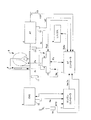
図1は、本発明のシステム構成を示す概略図である。 FIG. 1 is a schematic diagram showing the system configuration of the present invention.
この図1において、エンジン3にはトルクコンバータ5を備えた自動変速機4が連結され、トルクコンバータ5にはロックアップクラッチ6が配設されて運転状態に応じてロックアップ(締結状態)またはアンロックアップ(開放状態)を行うものである。
In FIG. 1, an automatic transmission 4 having a torque converter 5 is connected to the
トルクコンバータ5は、トルクコンバータ出力要素(タービン)と共に回転するロックアップクラッチ6を内蔵し、このロックアップクラッチ6は、トルクコンバータ入力要素(インペラ)に締結されるとき、トルクコンバータ5を入出力要素間が直結されたロックアップ状態にするものとする。
The torque converter 5 incorporates a
ロックアップクラッチ6は、その両側(前後)におけるトルクコンバータアプライ圧Paとトルクコンバータレリーズ圧Prとの差圧Pa−Prに応動し、レリーズ圧Prがアプライ圧Paよりも高いとロックアップクラッチ6は開放されてトルクコンバータ入出力要素間を直結せず、レリーズ圧Prがアプライ圧Paよりも低くなる時にロックアップクラッチ6は締結されてトルクコンバータ入出力要素間を直結するものである。
The lock-
そして、上記後者の締結に際して、ロックアップクラッチ6の締結力、つまりロックアップ容量は、上記の差圧Pa−Prにより決定し、この差圧が大きい程ロックアップクラッチ6の締結力が増大してロックアップ容量を増大する。
When the latter is engaged, the fastening force of the
差圧Pa−Prは、周知のロックアップコントロールバルブ7により制御し、このロックアップコントロールバルブ7には、アプライ圧Paおよびレリーズ圧Prを相互に対向するように作用させ、更にアプライ圧Paと同方向にバネの付勢力を、またレリーズ圧Prと同方向にばね力を作用させ、同時にレリーズ圧Prと同方向に信号圧Psolをそれぞれ作用させる。
The differential pressure Pa-Pr is controlled by a well-known
ロックアップコントロールバルブ7は、これら油圧とバネの付勢力が釣り合うよう差圧Pa−Prを決定する。
The
ここでロックアップコントロールバルブ7にかかる信号圧Psolは、ポンプ圧Ppを元圧としてロックアップソレノイド8がデューティ信号Dutyに応じて作り出すものである。
Here, the signal pressure Psol applied to the
マイクロコンピュータなどを主体にして構成されるATコントローラ1は、車両の運転状態に応じて差圧Ptを演算してデューティ信号Dutyに変換し、ロックアップソレノイド8を介して差圧Pa−Prを制御する。
The
ATコントローラ1には、車両の走行状態やドライバーの運転状況を示す信号、例えば、自動変速機4に設けた入力軸回転センサ16からの入力軸回転速度Ni、トルクコンバータ5への入力回転速度(=エンジン回転速度Ne)を検出するインペラ回転センサ11からのポンプインペラ回転速度Np、アクセル操作量センサ14からのアクセル操作量APO(またはスロットル開度TVO)、油温センサ12からの油温Tatf、車速センサ13からの車速VSPが入力される。そして図示しないインヒビタスイッチなどからの信号に基づいて、運転者が選択した変速レンジで変速制御及びロックアップ制御を行う。ここでは、Dレンジ、Lレンジ(低速レンジ)、Pレンジ、Rレンジを備えるものとする。
The
また、ATコントローラ1はエンジンコントローラ2からエンジン回転速度Ne、エンジントルクTeを受信する。
Further, the
そして、ATコントローラ1は、これらの検出信号によりロックアップクラッチ6の締結や解放あるいはスリップなどの制御を行う。
Then, the
ATコントローラ1は、車両の運転状態に応じてスムーズロックアップを行うもので、このスムーズロックアップは、例えば、アクセル操作量APOの変化が少なく、かつ車速VSPが緩やかに上昇する際に、コンバータ状態からスリップ状態を経てロックアップクラッチ6の締結を行うものである。
The AT
また、ATコントローラ1は、車両のコースト状態などの減速時に、所定の車速まで低下すると、エンジンストールを回避するために徐々にロックアップクラッチを解放するスムーズロックアップ解除制御を行うもので、このスムーズロックアップ解除制御は、例えば、アクセル操作量APOが解放状態で、かつ車速VSPが所定値まで減少すると、ロックアップクラッチを締結状態からスリップ状態を経てコンバータ状態に移行するものである。
The
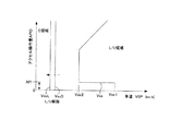
すなわち、図3で示すように、車速VSPとアクセル操作量APOの大きさに基づいて、スムーズロックアップ解除開始車速Vssと、ロックアップクラッチ6を即座に解放するロックアップ解除車速VsuD、VsuLが設定されて、スムーズロックアップ解除車速Vss以上の領域(図中右側)はロックアップクラッチ6を締結するロックアップ領域であり、ロックアップ解除車速VsuD、VsuLよりも車速VSPの小さい領域がコンバータ状態の領域(図中C領域)となる。そして、ロックアップ領域とコンバータ状態の領域の間がスリップ領域となる。
That is, as shown in FIG. 3, the smooth lockup release start vehicle speed Vss and the lockup release vehicle speeds VsuD and VsuL that immediately release the
ここで、ロックアップ解除車速VsuD、VsuLは、変速レンジに応じて設定されたロックアップ解除車速であり、VsuDは変速レンジがDレンジのときに用いるロックアップ解除車速で、VsuLはレンジのときに用いるロックアップ解除車速である。 Here, the lockup release vehicle speeds VsuD and VsuL are the lockup release vehicle speeds set according to the shift range, VsuD is the lockup release vehicle speed used when the shift range is the D range, and VsuL is the range. The lockup release vehicle speed to be used.
一方、ロックアップ解除開始車速はVssは、車速VSPとアクセル操作量APOに応じて変化し、アクセル操作量APO=0/8のときには、Vss1がロックアップ解除開始車速Vssであり、アクセル操作量APO=1/8程度(または図示しないアイドルスイッチがオンとなる領域)まではVss1をロックアップ解除開始車速Vssとする。 On the other hand, the lockup release start vehicle speed Vss changes according to the vehicle speed VSP and the accelerator operation amount APO. When the accelerator operation amount APO = 0/8, Vss1 is the lockup release start vehicle speed Vss, and the accelerator operation amount APO. Vss1 is set to the lockup release start vehicle speed Vss until about 1/8 (or an area where an idle switch (not shown) is turned on).
アクセル操作量APOが1/8以上になると、Vss1よりも小さいVss2をロックアップ解除開始車速Vssとし、さらにアクセル操作量APOが増大して5/8以上の領域では、ロックアップ解除開始車速VssがVss2からVss1へ向けて徐々に増大するように設定される。つまり、アクセル操作量APOが5/8以上ではアクセル操作量APOが大きいほどロックアップ解除開始車速Vssが大きくなる。なお、ロックアップ解除開始車速Vss1は低車速で設定され、例えば、20km/h等に設定される。 When the accelerator operation amount APO becomes 1/8 or more, Vss2 smaller than Vss1 is set as the lockup release start vehicle speed Vss. Further, in the region where the accelerator operation amount APO increases to 5/8 or more, the lockup release start vehicle speed Vss is It is set to gradually increase from Vss2 to Vss1. That is, when the accelerator operation amount APO is 5/8 or more, the lockup release start vehicle speed Vss increases as the accelerator operation amount APO increases. The lockup release start vehicle speed Vss1 is set at a low vehicle speed, for example, 20 km / h.
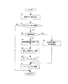
次に、図2は、ATコントローラ1で行われるスムースロックアップ解除制御の一例を示すフローチャートである。この処理は、ロックアップ解除が完了するまで、所定の周期(例えば、数十msec)で繰り返して実行される。
Next, FIG. 2 is a flowchart illustrating an example of smooth lockup release control performed by the
S1では、車速VSPとアクセル操作量APOを読み込んで、S2において、車速VSPがスムースロックアップ解除を開始する所定の車速Vss以下となったか否かを判定する。 In S1, the vehicle speed VSP and the accelerator operation amount APO are read, and in S2, it is determined whether or not the vehicle speed VSP is equal to or lower than a predetermined vehicle speed Vss at which smooth lockup release is started.
このスムーズロックアップ解除開始車速Vssは、図3で示したように、車速VSPとアクセル操作量APOの大きさに基づいて、Vss2からVss1の間で設定されるものである。 As shown in FIG. 3, the smooth lockup release start vehicle speed Vss is set between Vss2 and Vss1 based on the vehicle speed VSP and the accelerator operation amount APO.
車速VSPがスムーズロックアップ解除車速Vss以下になった場合には、S3以降でスムーズロックアップ解除制御を実行する。一方、車速VSPがスムーズロックアップ解除車速Vssを超えるときにはロックアップ状態を維持してそのまま終了する。 When the vehicle speed VSP becomes equal to or lower than the smooth lockup release vehicle speed Vss, the smooth lockup release control is executed after S3. On the other hand, when the vehicle speed VSP exceeds the smooth lockup release vehicle speed Vss, the lockup state is maintained and the process ends.
S3では、現在の変速レンジをインヒビタスイッチ(図示省略)からの信号に基づいて検出し、上記図3のマップから現在選択中の変速レンジに対応するロックアップ解除車速VsuDまたはVsuLを選択し、現在の車速VSPと比較する。 In S3, the current shift range is detected based on a signal from an inhibitor switch (not shown), and the lockup release vehicle speed VsuD or VsuL corresponding to the currently selected shift range is selected from the map of FIG. Compared with the vehicle speed VSP.
現在の車速VSPがロックアップ解除車速VsuD、L以上の場合にはS4に進んで、スリップ制御を主体とするロックアップ解除制御を行い、現在の車速VSPがロックアップ解除車速VsuD、Lを下回ったときには、S8へ進んでロックアップクラッチ6を完全に解放してエンジンのストールを回避する。つまり、差圧指令値Ptを予め設定した解放用の値に設定し、即座にロックアップクラッチ6の解放を行う。
When the current vehicle speed VSP is equal to or higher than the lockup release vehicle speed VsuD, L, the process proceeds to S4, where the lockup release control mainly including slip control is performed, and the current vehicle speed VSP falls below the lockup release vehicle speed VsuD, L. Sometimes, the process proceeds to S8 to completely release the
一方、車速VSPがロックアップ解除車速VsuD、VsuL以上の領域にあるS4では、スリップ制御を行って滑らかにロックアップクラッチ6を解放するため、解除用差圧指令値Puを予め設定したランプ(傾斜)により演算する。なお、このランプは緩減速用の緩やかな勾配を用いるのが望ましい。
On the other hand, in S4 where the vehicle speed VSP is in the region of the lockup release vehicle speeds VsuD and VsuL or higher, slip control is performed to release the
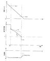
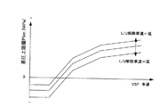
次に、S5では、上記差圧指令値Puを補正するため、図4のマップから、現在の車速VSPに応じた差圧上限値Plimを求める。この図4のマップは、車速VSPが低下するにつれて差圧上限値Plimが低下するように設定され、所定の車速を下回ると差圧上限値Plimは負の値となる。負の値はPa<Prの状態を示す。 Next, in S5, in order to correct the differential pressure command value Pu, a differential pressure upper limit value Plim corresponding to the current vehicle speed VSP is obtained from the map of FIG. The map of FIG. 4 is set such that the differential pressure upper limit value Plim decreases as the vehicle speed VSP decreases. When the vehicle speed VSP falls below a predetermined vehicle speed, the differential pressure upper limit value Plim becomes a negative value. A negative value indicates a state of Pa <Pr.
この差圧上限値Plimは、ロックアップ解除車速VsuDまたはVsuLへ低下するまでに差圧を所定値まで下げておき、前記従来例のようにロックアップクラッチ6の解放時に減速度の変動によるショックが発生するを防止する。このため、車速VSPが減少するにつれて差圧指令値の変化率(勾配)も大きくなるように設定されている。
The differential pressure upper limit value Plim is lowered to a predetermined value until the pressure drops to the lockup release vehicle speed VsuD or VsuL, and when the
次にS6では、上記S4で求めた差圧指令値Puと上記S5で求めた差圧上限値Plimとを比較して、小さい方を選択(セレクトロー)して差圧指令値Ptへ代入する。これにより、差圧指令値Ptは、解除用差圧指令値Puが車速VSPに応じた差圧上限値Plimを超えないように補正される。 Next, in S6, the differential pressure command value Pu obtained in S4 is compared with the differential pressure upper limit value Plim obtained in S5, and the smaller one is selected (select low) and substituted into the differential pressure command value Pt. . Thus, the differential pressure command value Pt is corrected so that the release differential pressure command value Pu does not exceed the differential pressure upper limit value Plim corresponding to the vehicle speed VSP.
そして、S7では差圧指令値Ptに応じたデューティ比を求めてロックアップソレノイド8を駆動する。
In S7, the
以上の制御により、スムーズロックアップ解除車速Vss以下になると、差圧上限値Plimを超えないように解除用差圧指令値Puが補正されて、ロックアップクラッチ6を徐々に解放するスムーズロックアップ解除制御(スリップ制御)が実行される。今、Dレンジで走行中に、緩減速によりスムーズロックアップ解除制御が行われる場合を図5に示す。
As a result of the above control, when the vehicle speed Vss is less than or equal to the smooth lockup release, the release differential pressure command value Pu is corrected so as not to exceed the differential pressure upper limit value Plim, and the smooth lockup release that gradually releases the
図5において、時刻T0まではロックアップ状態でコースト(緩減速)が行われている。そして時刻T0になると車速VSPがスムーズロックアップ解除車速Vss(この場合ではコースト=アクセル操作量APO=0/8であるから図3のVss1)に達しスムーズロックアップ解除制御が開始される。 In FIG. 5, coasting (slow deceleration) is performed in a locked-up state until time T0. At time T0, the vehicle speed VSP reaches the smooth lockup release vehicle speed Vss (in this case, coast = accelerator operation amount APO = 0/8, so Vss1 in FIG. 3), and the smooth lockup release control is started.
差圧指令値Ptは時刻T0で所定値まで低減された後、上記S4で予め設定したランプ(傾斜)により差圧指令値Puが演算され、徐々に低減されてロックアップクラッチ6の締結力は徐々に低減してスリップ状態になる。
After the differential pressure command value Pt is reduced to a predetermined value at time T0, the differential pressure command value Pu is calculated by the ramp (inclination) set in advance in S4 and gradually reduced, and the engagement force of the
そして、車速VSPは徐々に減少し、時刻T1になると、上記S6により、所定のランプから求めた解除用差圧指令値Puが、車速VSPの減少に応じて低下する差圧上限値Plimを超える。このため、差圧指令値Puは差圧上限値Plimによって規制され、出力される差圧指令値Ptは、S4で求めた差圧指令値Puよりも小さく補正される。 Then, the vehicle speed VSP gradually decreases. At time T1, the release differential pressure command value Pu obtained from the predetermined ramp exceeds the differential pressure upper limit value Plim that decreases in accordance with the decrease in the vehicle speed VSP at S6. . Therefore, the differential pressure command value Pu is regulated by the differential pressure upper limit value Plim, and the output differential pressure command value Pt is corrected to be smaller than the differential pressure command value Pu obtained in S4.
さらに車速VSPが減少して時刻T2になるとロックアップ解除車速VsuD未満になり、上記S3、S8により差圧指令値Ptはロックアップクラッチ6を完全に解放する所定値に設定され、ロックアップクラッチ6は即座に解放されてスリップ状態からコンバータ状態に移行する。
When the vehicle speed VSP further decreases and reaches time T2, it becomes less than the lockup release vehicle speed VsuD, and the differential pressure command value Pt is set to a predetermined value for completely releasing the
この時刻T2の時点では、差圧上限値Plimにより差圧指令値Ptが解除用差圧指令値Puよりも小さな値になっているので、この時点でロックアップクラッチ6の完全解放を行っても減速度(負の加速度)が急変することはなく、図示のように緩やかに減速度が減少し、ショックを発生することなく緩減速でのスムーズロックアップ解除制御を実現できる。
At the time T2, the differential pressure command value Pt is smaller than the release differential pressure command value Pu due to the differential pressure upper limit value Plim. Therefore, even if the
一方、Dレンジで走行中に急減速を行った場合について図6を参照しながら説明する。 On the other hand, the case where sudden deceleration is performed while traveling in the D range will be described with reference to FIG.
図6において、時刻T0まではロックアップ状態でコースト(緩減速)が行われている。そして時刻T0になると急減速が行われ、車速VSPがスムーズロックアップ解除車速Vss(例えば、図3のVss1)に達しスムーズロックアップ解除制御が開始される。 In FIG. 6, coasting (slow deceleration) is performed in a locked-up state until time T0. At time T0, sudden deceleration is performed, the vehicle speed VSP reaches the smooth lockup release vehicle speed Vss (for example, Vss1 in FIG. 3), and smooth lockup release control is started.
差圧指令値Ptは時刻T0で所定値まで低減された後、上記S4で予め設定したランプ(傾斜)により差圧指令値Puが演算されるが、急減速により車速VSPの低下が速いので、時刻T0以降から差圧指令値Puは差圧上限値Plimに制限される。 After the differential pressure command value Pt is reduced to a predetermined value at time T0, the differential pressure command value Pu is calculated by the ramp (inclination) set in advance in S4. However, because the vehicle speed VSP decreases rapidly due to sudden deceleration, From time T0 onward, the differential pressure command value Pu is limited to the differential pressure upper limit value Plim.
以降、急減速中は差圧指令値Ptが差圧上限値Plimによって規制されながら減少し、時刻T1になると車速VSPはロックアップ解除車速VsuD未満になり、上記S3、S8により差圧指令値Ptはロックアップクラッチ6を完全に解放する所定値に設定され、ロックアップクラッチ6は即座に解放されてスリップ状態からコンバータ状態に移行する。
Thereafter, during the rapid deceleration, the differential pressure command value Pt decreases while being regulated by the differential pressure upper limit value Plim. At time T1, the vehicle speed VSP becomes lower than the lockup release vehicle speed VsuD, and the differential pressure command value Pt is obtained by the above S3 and S8. Is set to a predetermined value for completely releasing the lock-up
この時刻T1の時点では、急減速時においても上記緩減速と同様に、差圧上限値Plimにより差圧指令値Ptが解除用差圧指令値Puよりも小さな値になっており、かつ、緩減速時と同様の差圧指令値Pt≒0となっている。 At the time T1, at the time of sudden deceleration, the differential pressure command value Pt is smaller than the release differential pressure command value Pu by the differential pressure upper limit value Plim as in the case of the slow deceleration. The differential pressure command value Pt≈0 is the same as that during deceleration.
この時点でロックアップクラッチ6の完全解放を行っても減速度(負の加速度)が急変することはなく、図中実線のように緩やかに減速度が減少し、ショックを発生することなく緩減速でのスムーズロックアップ解除制御を実現できる。
Even if the lock-up
一方、従来例の場合では、緩減速用のランプ(例えば、図中破線のPu)で差圧指令値の漸減が行われるので、ロックアップ解除車速VsuDに達した時点ではまだ差圧が高く締結力も大きい状態である。この状態からロックアップクラッチ6を一気に解放すると、車両に発生する加速度は、図中一点鎖線のように解放後に一気に減速度が増大した後、減速度が増大することでショック発生していたのである。
On the other hand, in the case of the conventional example, since the differential pressure command value is gradually decreased by a slow deceleration ramp (for example, Pu in the figure), the differential pressure is still high when the lockup release vehicle speed VsuD is reached. The force is also large. When the lock-up
これに対して本発明によれば、スムーズロックアップ解除制御のランプを緩減速用の設定としておき、この差圧指令値の特性を図4で示したマップにより、車速VSPの低下に伴って差圧上限値Plimを減少させ、この差圧上限値Plimで差圧指令値Puを補正するようにしたたため、減速度の大小にかかわらずロックアップ解除車速VsuD(またはVsuL)となる時点の差圧指令値Ptをほぼ一定にすることが可能となり、前記従来例のように減速度(または加速度)の監視を行うことなく、減速度の大きさに係わらずショックの発生を抑制して、滑らかにロックアップクラッチ6のスムーズロックアップ解除を実現することが可能となる。
On the other hand, according to the present invention, the smooth lockup release control lamp is set for slow deceleration, and the characteristics of the differential pressure command value are changed according to the decrease in the vehicle speed VSP according to the map shown in FIG. Since the pressure upper limit value Plim is decreased and the pressure difference command value Pu is corrected with the pressure difference upper limit value Plim, the pressure difference when the lockup release vehicle speed VsuD (or VsuL) is reached regardless of the magnitude of the deceleration. It becomes possible to make the command value Pt substantially constant, and it is possible to suppress the occurrence of shock regardless of the magnitude of the deceleration, without monitoring the deceleration (or acceleration) as in the conventional example, and smoothly It is possible to realize smooth lockup release of the
図7は、第2の実施形態を示し、前記第1実施形態の図4に示した差圧上限値Plimのマップを、自動変速機4の油温Tatfに応じて変更するようにしたもので、その他の構成は前記第1実施形態と同様である。 FIG. 7 shows the second embodiment, in which the map of the differential pressure upper limit value Plim shown in FIG. 4 of the first embodiment is changed according to the oil temperature Tatf of the automatic transmission 4. Other configurations are the same as those of the first embodiment.
図7のマップは、油温センサ12が検出した油温Tatf毎に設定され、油温Tatfが高くなると差圧上限値Plimも高くなり、油温Tatfが低下すると差圧上限値Plimも低下(ロックアップクラッチ6の解放側へ移動)する。ただし、各油温の特性、つまり車速変化に対する差圧上限値Plimの変化率(傾き)は同一とする。
The map of FIG. 7 is set for each oil temperature Tatf detected by the
この場合では、油温が低いほど油圧の応答速度は低下するので、車速VSPに対する差圧上限値Plimを基準値(図中油温=中)よりも全体的に低く設定し、油温が高いほど油圧の応答速度は向上するので、車速VSPに対する差圧上限値Plimを基準値(図中油温=中)よりも全体的に高く設定する。 In this case, since the response speed of the hydraulic pressure decreases as the oil temperature decreases, the differential pressure upper limit value Plim with respect to the vehicle speed VSP is set lower overall than the reference value (oil temperature = medium in the figure), and as the oil temperature increases. Since the response speed of the hydraulic pressure is improved, the differential pressure upper limit value Plim with respect to the vehicle speed VSP is set to be higher overall than the reference value (oil temperature = medium in the figure).
これにより油温Tatfの変化による油圧の応答遅れを相殺するように設定することができる。 As a result, the oil pressure response delay due to the change in the oil temperature Tatf can be set to cancel.
図8は、第3の実施形態を示し、前記第1実施形態の図4に示した差圧上限値Plimのマップを、ロックアップ解除車速VsuDまたはVsuLの大きさに応じて変更するようにしたもので、その他の構成は前記第1実施形態と同様である。 FIG. 8 shows the third embodiment, and the map of the differential pressure upper limit value Plim shown in FIG. 4 of the first embodiment is changed according to the magnitude of the lockup release vehicle speed VsuD or VsuL. However, other configurations are the same as those in the first embodiment.
図8のマップは、インヒビタスイッチなどが検出した変速レンジ毎に設定され、ロックアップ解除車速が低いほど差圧上限値Plimを高く設定し、ロックアップ解除車速が高いほど差圧上限値Plimを低く設定する。 The map of FIG. 8 is set for each shift range detected by the inhibitor switch, etc., and the differential pressure upper limit value Plim is set higher as the lockup release vehicle speed is lower, and the differential pressure upper limit value Plim is lowered as the lockup release vehicle speed is higher. Set.
ロックアップ解除車速が低い場合は、例えば、図3のVsuLの場合であり、車速の差分が大きいため、ロックアップ解除開始車速Vssから高い差圧上限値Plimでスムーズロックアップ解除制御を行っても、ロックアップ解除車速VsuLに到達する時点では、差圧指令値Ptが十分低くなっているので、上述のようなショックを発生することなく滑らかにスムーズロックアップ解除制御を実現できる。 The case where the lockup release vehicle speed is low is, for example, the case of VsuL in FIG. 3. Since the difference in vehicle speed is large, even if smooth lockup release control is performed with a high differential pressure upper limit Plim from the lockup release start vehicle speed Vss. Since the differential pressure command value Pt is sufficiently low when the lockup release vehicle speed VsuL is reached, smooth lockup release control can be realized smoothly without causing the above-described shock.
ロックアップ解除車速が高い場合は、例えば、図3のVsuDの場合であり、車速の差分が小さいため、ロックアップ解除開始車速Vssから低いい差圧上限値Plimでスムーズロックアップ解除制御を行わないと、ロックアップ解除車速VsuLに到達する時点で、差圧指令値Ptが十分低くならないので、上述のようなショックを防止するため、差圧上限値Plimを全体的に低く設定する。 When the lockup release vehicle speed is high, for example, in the case of VsuD in FIG. 3, since the difference in vehicle speed is small, the smooth lockup release control is not performed with the lower differential pressure upper limit Plim from the lockup release start vehicle speed Vss. When the lockup release vehicle speed VsuL is reached, the differential pressure command value Pt does not become sufficiently low. Therefore, the differential pressure upper limit value Plim is set to be low overall in order to prevent such a shock.
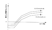
図9は、第4の実施形態を示し、前記第1実施形態の図4に示した差圧上限値Plimのマップを、エンジントルクまたはトルクコンバータ5への入力トルクの大きさに応じて変更するようにしたもので、その他の構成は前記第1実施形態と同様である。 FIG. 9 shows the fourth embodiment, and the map of the differential pressure upper limit value Plim shown in FIG. 4 of the first embodiment is changed according to the engine torque or the magnitude of the input torque to the torque converter 5. The other configurations are the same as those in the first embodiment.
図9のマップは、エンジンコントローラ2から受信したエンジントルクTe、あるいはエンジン回転速度Neとアクセル操作量APOから推定し演算したエンジントルク毎に設定され、エンジントルクが大きいほど差圧上限値Plimを高く設定し、エンジントルクが小さいほど差圧上限値Plimを低く設定する。 The map of FIG. 9 is set for each engine torque Te estimated from the engine torque Te received from the engine controller 2 or the engine rotational speed Ne and the accelerator operation amount APO, and the differential pressure upper limit value Plim increases as the engine torque increases. The differential pressure upper limit Plim is set lower as the engine torque is smaller.
エンジントルクが大きい場合には、ロックアップ解除時にロックアップクラッチ6のスリップが早期に発生するので、スリップが過大にならないように差圧上限値Plimを高くする。逆にエンジントルクが低い場合は、ロックアップ解除時のスリップ発生は遅れるので、低い差圧上限値Plimでスムーズロックアップ解除制御を行っても、スリップが過大になることはない。
When the engine torque is large, the
以上のように、本発明によれば、減速度の大小にかかわらずスムーズロックアップ解除制御を滑らかに行うことができるので、運転性に優れたロックアップクラッチを備えたトルクコンバータを有する自動変速機の制御装置に適用することができる。 As described above, according to the present invention, smooth lock-up release control can be performed smoothly regardless of the magnitude of deceleration, so that an automatic transmission having a torque converter provided with a lock-up clutch having excellent drivability It can be applied to the control device.
1 ATコントローラ
4 自動変速機
5 トルクコンバータ
6 ロックアップクラッチ
1 AT controller 4 Automatic transmission 5
Claims (5)
車両の運転状態に基づいて、前記ロックアップクラッチに供給する差圧指令値を演算して、前記トルクコンバータのコンバータ状態とロックアップ状態とをスリップ状態を介して切り換えるロックアップ制御手段と、を備え、
前記ロックアップ制御手段は、
車速を検出する車速検出手段と、
前記車速が予め設定した第1の車速以下になると、締結中のロックアップクラッチを徐々に解放するスムーズロックアップ解除手段と、
前記車速が予め設定されて前記第1の車速よりも低い第2の車速以下になると、ロックアップクラッチを即座に解放するロックアップ解放手段と、
を備え、
前記スムーズロックアップ解除手段は、予め設定した変化率で前記差圧指令値を徐々に低減するように演算する差圧指令値演算手段を備えた自動変速機の制御装置において、
前記車速が低下するにつれて前記予め設定した変化率よりも更に大きな変化率で前記差圧指令値が更に低減するように補正する差圧指令値補正手段を備えたことを特徴とする自動変速機の制御装置。 A torque converter interposed between the engine and the automatic transmission and having a lock-up clutch;
Lockup control means for calculating a differential pressure command value to be supplied to the lockup clutch based on a driving state of the vehicle and switching between a converter state and a lockup state of the torque converter via a slip state. ,
The lock-up control means includes
Vehicle speed detection means for detecting the vehicle speed;
Smooth lockup release means for gradually releasing the lockup clutch being engaged when the vehicle speed is equal to or lower than a preset first vehicle speed;
A lockup release means for immediately releasing the lockup clutch when the vehicle speed is preset and lower than a second vehicle speed lower than the first vehicle speed ;
With
The smooth lockup release means is an automatic transmission control device comprising differential pressure command value calculation means for calculating so as to gradually reduce the differential pressure command value at a preset rate of change .
An automatic transmission comprising: a differential pressure command value correcting means for correcting the differential pressure command value so as to further decrease at a rate of change greater than the preset rate of change as the vehicle speed decreases. Control device.
前記差圧指令値演算手段の演算結果と、前記上限値とを比較して、小さい方を差圧指令値として出力することを特徴とする請求項1に記載の自動変速機の制御装置。 The differential pressure command value correcting means includes an upper limit regulating means for gradually lowering the upper limit value of the differential pressure command value as the vehicle speed decreases ,
2. The control apparatus for an automatic transmission according to claim 1, wherein the calculation result of the differential pressure command value calculation means is compared with the upper limit value, and the smaller one is output as a differential pressure command value.
前記上限値規制手段は、前記第2の車速が高いほど前記上限値を低く設定することを特徴とする請求項2に記載の自動変速機の制御装置。 The lock-up releasing means sets the second vehicle speed for each preset shift range,
3. The control device for an automatic transmission according to claim 2, wherein the upper limit value regulating unit sets the upper limit value lower as the second vehicle speed is higher . 4.
Priority Applications (2)
| Application Number | Priority Date | Filing Date | Title |
|---|---|---|---|
| JP2004103720A JP4072829B2 (en) | 2004-03-31 | 2004-03-31 | Control device for automatic transmission |
| US11/088,264 US7287631B2 (en) | 2004-03-31 | 2005-03-24 | Lock-up control for torque converter |
Applications Claiming Priority (1)
| Application Number | Priority Date | Filing Date | Title |
|---|---|---|---|
| JP2004103720A JP4072829B2 (en) | 2004-03-31 | 2004-03-31 | Control device for automatic transmission |
Publications (2)
| Publication Number | Publication Date |
|---|---|
| JP2005291250A JP2005291250A (en) | 2005-10-20 |
| JP4072829B2 true JP4072829B2 (en) | 2008-04-09 |
Family
ID=35053067
Family Applications (1)
| Application Number | Title | Priority Date | Filing Date |
|---|---|---|---|
| JP2004103720A Expired - Lifetime JP4072829B2 (en) | 2004-03-31 | 2004-03-31 | Control device for automatic transmission |
Country Status (2)
| Country | Link |
|---|---|
| US (1) | US7287631B2 (en) |
| JP (1) | JP4072829B2 (en) |
Families Citing this family (9)
| Publication number | Priority date | Publication date | Assignee | Title |
|---|---|---|---|---|
| JP4054778B2 (en) * | 2004-03-31 | 2008-03-05 | ジヤトコ株式会社 | Control device for automatic transmission |
| JP2006300206A (en) * | 2005-04-20 | 2006-11-02 | Toyota Motor Corp | Control device of lock-up clutch for vehicle |
| JP2008032109A (en) * | 2006-07-28 | 2008-02-14 | Aisin Seiki Co Ltd | Controller for lock-up clutch |
| KR101234628B1 (en) * | 2006-12-09 | 2013-02-19 | 현대자동차주식회사 | Method for controlling damper clutch of automatic transmission for vehicles |
| JP4598005B2 (en) * | 2007-01-25 | 2010-12-15 | 本田技研工業株式会社 | Control device for automatic transmission for vehicle |
| JP4941139B2 (en) * | 2007-07-09 | 2012-05-30 | トヨタ自動車株式会社 | Control device for lock-up clutch |
| JP5068280B2 (en) * | 2009-04-20 | 2012-11-07 | ジヤトコ株式会社 | Lockup control device and lockup control method for automatic transmission |
| WO2014148147A1 (en) * | 2013-03-21 | 2014-09-25 | ジヤトコ株式会社 | Vehicle control device, and vehicle control method |
| JP6288279B2 (en) * | 2014-08-29 | 2018-03-07 | 日産自動車株式会社 | Vehicle lock-up clutch control device |
Family Cites Families (9)
| Publication number | Priority date | Publication date | Assignee | Title |
|---|---|---|---|---|
| JPH05187540A (en) | 1992-01-09 | 1993-07-27 | Jatco Corp | Lock-up clutch control device |
| JP3402805B2 (en) | 1994-11-30 | 2003-05-06 | ジヤトコ株式会社 | Lockup control device for automatic transmission |
| JPH08159270A (en) * | 1994-12-12 | 1996-06-21 | Nissan Motor Co Ltd | Lockup release control device for torque converter |
| JPH08170725A (en) * | 1994-12-15 | 1996-07-02 | Nissan Motor Co Ltd | Controller of torque converter with lock-up clutch |
| JP3240939B2 (en) * | 1996-11-07 | 2001-12-25 | 日産自動車株式会社 | Lockup control device for torque converter |
| JP3678573B2 (en) | 1998-02-06 | 2005-08-03 | 株式会社日立製作所 | Automatic transmission lockup control device |
| JP3496526B2 (en) * | 1998-07-14 | 2004-02-16 | 日産自動車株式会社 | Lockup control device for automatic transmission |
| DE19955799A1 (en) * | 1998-11-19 | 2000-05-31 | Hitachi Ltd | Arrangement for controlling automatic gearboxes has controller that changes initial working pressure value in agreement with drive force during transition period between coupling states |
| JP4334394B2 (en) | 2004-03-31 | 2009-09-30 | ジヤトコ株式会社 | Control device for automatic transmission |
-
2004
- 2004-03-31 JP JP2004103720A patent/JP4072829B2/en not_active Expired - Lifetime
-
2005
- 2005-03-24 US US11/088,264 patent/US7287631B2/en active Active
Also Published As
| Publication number | Publication date |
|---|---|
| US20050217957A1 (en) | 2005-10-06 |
| JP2005291250A (en) | 2005-10-20 |
| US7287631B2 (en) | 2007-10-30 |
Similar Documents
| Publication | Publication Date | Title |
|---|---|---|
| US7328095B2 (en) | Lock-up control for torque converter | |
| US6740005B2 (en) | Shift control apparatus of automatic transmission of motor vehicle | |
| JP4731153B2 (en) | Control device for automatic transmission | |
| JP4133989B2 (en) | Control device for continuously variable transmission | |
| US7287631B2 (en) | Lock-up control for torque converter | |
| JP3496526B2 (en) | Lockup control device for automatic transmission | |
| JP2009150494A (en) | Lock-up clutch control device of automatic change gear | |
| JP2005042742A (en) | Starting controller for vehicle | |
| JP4945601B2 (en) | Automatic transmission lockup control device | |
| US7282009B2 (en) | Control of lock-up clutch | |
| JP4525389B2 (en) | Control device for automatic transmission | |
| JPH1137267A (en) | Hydraulic pressure control device of vehicular automatic transmission | |
| JP5467973B2 (en) | Automatic transmission for vehicle | |
| JP3286012B2 (en) | Fastening force control device for automatic transmission | |
| JP2010210008A (en) | Control device for lock-up clutch of vehicle | |
| JPH05231530A (en) | Controller of vehicle lock-up clutch | |
| JP2005172078A (en) | Lock-up control device for torque converter | |
| JP2576733B2 (en) | Slip control device for vehicle direct coupling clutch | |
| JP4645119B2 (en) | Control device for continuously variable transmission | |
| JP2003065433A (en) | Control device for lockup clutch | |
| JP4069599B2 (en) | Control device for lock-up clutch | |
| JP4622501B2 (en) | Control device for automatic transmission | |
| JP5068280B2 (en) | Lockup control device and lockup control method for automatic transmission | |
| JP2004340289A (en) | Control device and method of vehicle | |
| JP2003074694A (en) | Control unit of lockup clutch |
Legal Events
| Date | Code | Title | Description |
|---|---|---|---|
| A621 | Written request for application examination |
Free format text: JAPANESE INTERMEDIATE CODE: A621 Effective date: 20050818 |
|
| A977 | Report on retrieval |
Free format text: JAPANESE INTERMEDIATE CODE: A971007 Effective date: 20070906 |
|
| A131 | Notification of reasons for refusal |
Free format text: JAPANESE INTERMEDIATE CODE: A131 Effective date: 20070911 |
|
| A521 | Request for written amendment filed |
Free format text: JAPANESE INTERMEDIATE CODE: A523 Effective date: 20071112 |
|
| TRDD | Decision of grant or rejection written | ||
| A01 | Written decision to grant a patent or to grant a registration (utility model) |
Free format text: JAPANESE INTERMEDIATE CODE: A01 Effective date: 20080108 |
|
| A61 | First payment of annual fees (during grant procedure) |
Free format text: JAPANESE INTERMEDIATE CODE: A61 Effective date: 20080115 |
|
| FPAY | Renewal fee payment (event date is renewal date of database) |
Free format text: PAYMENT UNTIL: 20110201 Year of fee payment: 3 |
|
| R150 | Certificate of patent or registration of utility model |
Free format text: JAPANESE INTERMEDIATE CODE: R150 Ref document number: 4072829 Country of ref document: JP Free format text: JAPANESE INTERMEDIATE CODE: R150 |
|
| FPAY | Renewal fee payment (event date is renewal date of database) |
Free format text: PAYMENT UNTIL: 20110201 Year of fee payment: 3 |
|
| FPAY | Renewal fee payment (event date is renewal date of database) |
Free format text: PAYMENT UNTIL: 20120201 Year of fee payment: 4 |
|
| FPAY | Renewal fee payment (event date is renewal date of database) |
Free format text: PAYMENT UNTIL: 20120201 Year of fee payment: 4 |
|
| FPAY | Renewal fee payment (event date is renewal date of database) |
Free format text: PAYMENT UNTIL: 20130201 Year of fee payment: 5 |
|
| FPAY | Renewal fee payment (event date is renewal date of database) |
Free format text: PAYMENT UNTIL: 20130201 Year of fee payment: 5 |
|
| FPAY | Renewal fee payment (event date is renewal date of database) |
Free format text: PAYMENT UNTIL: 20140201 Year of fee payment: 6 |
|
| FPAY | Renewal fee payment (event date is renewal date of database) |
Free format text: PAYMENT UNTIL: 20140201 Year of fee payment: 6 |
|
| FPAY | Renewal fee payment (event date is renewal date of database) |
Free format text: PAYMENT UNTIL: 20150201 Year of fee payment: 7 |
|
| S111 | Request for change of ownership or part of ownership |
Free format text: JAPANESE INTERMEDIATE CODE: R313117 |
|
| R350 | Written notification of registration of transfer |
Free format text: JAPANESE INTERMEDIATE CODE: R350 |