JP3879413B2 - Conveying system and rotating electric machine - Google Patents
Conveying system and rotating electric machine Download PDFInfo
- Publication number
- JP3879413B2 JP3879413B2 JP2001053425A JP2001053425A JP3879413B2 JP 3879413 B2 JP3879413 B2 JP 3879413B2 JP 2001053425 A JP2001053425 A JP 2001053425A JP 2001053425 A JP2001053425 A JP 2001053425A JP 3879413 B2 JP3879413 B2 JP 3879413B2
- Authority
- JP
- Japan
- Prior art keywords
- field
- field magnets
- magnetic pole
- magnets
- electrical machine
- Prior art date
- Legal status (The legal status is an assumption and is not a legal conclusion. Google has not performed a legal analysis and makes no representation as to the accuracy of the status listed.)
- Expired - Fee Related
Links
Images


Classifications
-
- H—ELECTRICITY
- H02—GENERATION; CONVERSION OR DISTRIBUTION OF ELECTRIC POWER
- H02K—DYNAMO-ELECTRIC MACHINES
- H02K21/00—Synchronous motors having permanent magnets; Synchronous generators having permanent magnets
- H02K21/02—Details
- H02K21/021—Means for mechanical adjustment of the excitation flux
- H02K21/028—Means for mechanical adjustment of the excitation flux by modifying the magnetic circuit within the field or the armature, e.g. by using shunts, by adjusting the magnets position, by vectorial combination of field or armature sections
- H02K21/029—Vectorial combination of the fluxes generated by a plurality of field sections or of the voltages induced in a plurality of armature sections
-
- B—PERFORMING OPERATIONS; TRANSPORTING
- B61—RAILWAYS
- B61C—LOCOMOTIVES; MOTOR RAILCARS
- B61C9/00—Locomotives or motor railcars characterised by the type of transmission system used; Transmission systems specially adapted for locomotives or motor railcars
- B61C9/38—Transmission systems in or for locomotives or motor railcars with electric motor propulsion
- B61C9/48—Transmission systems in or for locomotives or motor railcars with electric motor propulsion with motors supported on vehicle frames and driving axles, e.g. axle or nose suspension
-
- B—PERFORMING OPERATIONS; TRANSPORTING
- B61—RAILWAYS
- B61F—RAIL VEHICLE SUSPENSIONS, e.g. UNDERFRAMES, BOGIES OR ARRANGEMENTS OF WHEEL AXLES; RAIL VEHICLES FOR USE ON TRACKS OF DIFFERENT WIDTH; PREVENTING DERAILING OF RAIL VEHICLES; WHEEL GUARDS, OBSTRUCTION REMOVERS OR THE LIKE FOR RAIL VEHICLES
- B61F3/00—Types of bogies
- B61F3/02—Types of bogies with more than one axle
- B61F3/04—Types of bogies with more than one axle with driven axles or wheels
-
- B—PERFORMING OPERATIONS; TRANSPORTING
- B61—RAILWAYS
- B61F—RAIL VEHICLE SUSPENSIONS, e.g. UNDERFRAMES, BOGIES OR ARRANGEMENTS OF WHEEL AXLES; RAIL VEHICLES FOR USE ON TRACKS OF DIFFERENT WIDTH; PREVENTING DERAILING OF RAIL VEHICLES; WHEEL GUARDS, OBSTRUCTION REMOVERS OR THE LIKE FOR RAIL VEHICLES
- B61F3/00—Types of bogies
- B61F3/16—Types of bogies with a separate axle for each wheel
-
- H—ELECTRICITY
- H02—GENERATION; CONVERSION OR DISTRIBUTION OF ELECTRIC POWER
- H02K—DYNAMO-ELECTRIC MACHINES
- H02K16/00—Machines with more than one rotor or stator
- H02K16/02—Machines with one stator and two or more rotors
-
- Y—GENERAL TAGGING OF NEW TECHNOLOGICAL DEVELOPMENTS; GENERAL TAGGING OF CROSS-SECTIONAL TECHNOLOGIES SPANNING OVER SEVERAL SECTIONS OF THE IPC; TECHNICAL SUBJECTS COVERED BY FORMER USPC CROSS-REFERENCE ART COLLECTIONS [XRACs] AND DIGESTS
- Y02—TECHNOLOGIES OR APPLICATIONS FOR MITIGATION OR ADAPTATION AGAINST CLIMATE CHANGE
- Y02T—CLIMATE CHANGE MITIGATION TECHNOLOGIES RELATED TO TRANSPORTATION
- Y02T30/00—Transportation of goods or passengers via railways, e.g. energy recovery or reducing air resistance
Landscapes
- Engineering & Computer Science (AREA)
- Mechanical Engineering (AREA)
- Power Engineering (AREA)
- Chemical & Material Sciences (AREA)
- Combustion & Propulsion (AREA)
- Transportation (AREA)
- Permanent Magnet Type Synchronous Machine (AREA)
- Permanent Field Magnets Of Synchronous Machinery (AREA)
- Iron Core Of Rotating Electric Machines (AREA)
Description
【0001】
【発明の属する技術分野】
本発明は永久磁石を界磁に用いた回転電機に係り、特に搬送システムの駆動,回生を行う回転電機およびその制御方法に関する。
【0002】
【従来の技術】
従来技術による永久磁石回転電機において、誘導起電力Eは回転子に配置されている永久磁石が発生する一定磁束Φと回転電機の回転角速度ωによって決定される。つまり、回転電機の回転角速度ω(回転数)が上昇すると、回転電機の誘導起電力は比例して上昇する。
【0003】
よって、低速領域で高トルクが得られるが、回転数の可変速範囲が狭いために高速領域の運転は困難であったが、弱め界磁制御技術により高速運転領域を広げる。
【0004】
また、特開2000−155262では永久磁石が発生する磁束の弱め界磁方法として、ばねとガバナを用いて遠心力を利用した機構を用いる。
【0005】
【発明が解決しようとする課題】
従来技術で述べた弱め界磁制御技術により高速運転領域を広げることは、弱め界磁電流による発熱や効率低下などにより限界がある。
【0006】
また、特開2000−155262による方法では、ばねとガバナの構造が複雑である。
【0007】
本発明は、簡単な構造で永久磁石が発生する磁束の弱め界磁が可能な回転電機を提供し、更に、搬送システムの発進等の低回転領域における高トルク特性と、高回転領域において高出力特性が得られる永久磁石形回転電機を備えた搬送システムを提供することを目的とする。
【0008】
【課題を解決するための手段】
本発明は、回転電機において、巻線を有する固定子と、回転方向に順次異なった極性のものを並べて構成した第1及び第2の界磁用磁石が回転軸上に設けられたものであって、この第1及び第2の界磁用磁石が固定子の磁極に対向するように固定子に対して配置された回転子とを有し、第1及び第2の界磁用磁石の磁気作用力と回転子に発生するトルクの方向とに応じて第1及び第2の界磁用磁石が回転軸の軸方向と回転方向に変位できるように構成されていることを特徴とする。また、本発明は、回転電機において、巻線を有する固定子と、回転方向に順次異なった極性のものを並べて構成した第1乃至第3の界磁用磁石が回転軸上に設けられたものであって、この第1乃至第3の界磁用磁石が固定子の磁極に対向するように固定子に対して配置された回転子とを有し、第1乃至第3の界磁用磁石の磁気作用力と回転子に発生するトルクの方向とに応じて、回転軸上に固定された第3の界磁用磁石の両端に位置する第1及び第2の界磁用磁石が回転軸の軸方向と回転方向に変位できるように構成されていることを特徴とする。
【0010】
本発明は、搬送システムにおいて、車輪を有する台車と、この台車の動力源であって、車輪の車軸に動力を伝達する回転電機と、外部から前記台車内に電力を取り入れる集電装置と、回転電機の電力を制御する電力変換器とを有し、回転電機は、巻線を有する固定子と、回転方向に順次異なった極性のものを並べて構成した第1及び第2の界磁用磁石が回転軸上に設けられたものであって、この第1及び第2の界磁用磁石が固定子の磁極に対向するように固定子に対して配置された回転子とを有するものであり、第1及び第2の界磁用磁石の磁気作用力と回転子に発生するトルクの方向とに応じて、第1の界磁用磁石が第2の界磁用磁石に対して回転軸の軸方向と回転方向に変位できるように構成されたものであることを特徴とする。また、本発明は、搬送システムシステムにおいて、車輪を有する台車と、この台車の動力源であって、車輪の車軸に動力を伝達する回転電機と、外部から前記台車内に電力を取り入れる集電装置と、回転電機の電力を制御する電力変換器とを有し、回転電機は、巻線を有する固定子と、回転方向に順次異なった極性のものを並べて構成した第1及び第2の界磁用磁石が回転軸上に設けられたものであって、この第1及び第2の界磁用磁石が固定子の磁極に対向するように固定子に対して配置された回転子とを有するものであり、第1及び第2の界磁用磁石の磁気作用力と前記回転子に発生するトルクの方向とに応じて第1及び第2の界磁用磁石が回転軸の軸方向と回転方向に変位できるように構成されたものであることを特徴とする。さらに、本発明は、搬送システムにおいて、車輪を有する台車と、この台車の動力源であって、車輪の車軸に動力を伝達する回転電機と、外部から前記台車内に電力を取り入れる集電装置と、回転電機の電力を制御する電力変換器とを有し、回転電機は、巻線を有する固定子と、回転方向に順次異なった極性のものを並べて構成した第1乃至第3の界磁用磁石が回転軸上に設けられたものであって、この第1乃至第3の界磁用磁石が前記固定子の磁極に対向するように前記固定子に対して配置された回転子とを有するものであり、第1乃至第3の界磁用磁石の磁気作用力と回転子に発生するトルクの方向とに応じて、回転軸上に固定された第3の界磁用磁石の両端に位置する第1及び第2の界磁用磁石が回転軸の軸方向と回転方向に変位できるように構成されたものであることを特徴とする。
【0011】
【発明の実施の形態】
以下に本発明の実施形態について説明する。
【0012】
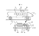
図1は本実施例の永久磁石形同期回転電機の配置レイアウトを示したものである。
【0013】
回転電機を動力源として用いる搬送システムには様々であるが、その一例として、鉄道車両システムの実施例を示したのが図1である。
【0014】
図1において、回転電機2と直接又は間接に取り付けられた車輪83を備えて、前記回転電機の電力を制御する電力変換器4と、電気車1と集電装置85を有する鉄道車両システムである。
【0015】
ここに、前記電気車とは電気を動力として使用する鉄道車両である。また、鉄道車両システムも含めた広い意味の搬送システムにおいては台車に相当する意味を持つ。
【0016】
また、集電装置は車外から電気車(もしくは台車)内に電力を取り入れる装置であり、架空線86式ではパンターグラフ、第三軌条式では集電器であり、工場内の搬送システムには非接触集電装置でもある。
【0017】
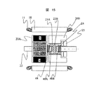
図1の下に示す回転電機2は継手81と歯車装置82を介して車軸84に動力を伝達する構造を示す。前記回転電機2の左右には図2に示すストッパー24を必要に応じてシャフトと平行に可変可能な機構25R,25Lを持つ。
【0018】
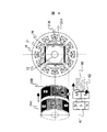
図2は図1の回転電機の回転子同磁極中心がずれた場合の概略を示す。固定子鉄心10には電機子巻線11がスロット内に巻装されており、内部に冷媒が流れる冷却路12をもったハウジング13に結合されている。
【0019】
永久磁石埋め込み型回転子20はシャフト22に固定した第1回転子20Aとシャフト22と分離した第2回転子20Bからなる。勿論、永久磁石埋め込み型回転子のみならず、表面磁石型回転子でも良い。
【0020】
第1回転子20Aには、永久磁石21Aが回転方向に順次異なった極性の磁極が並んでいる。同じく、第2回転子20Bには、永久磁石21Bが回転方向に順次異なった極性の磁極が並んでいる。第1の界磁用磁石と第2回転子の2つの回転子を同一軸上に配置した界磁用磁石は固定子磁極に対向している。
【0021】
第2回転子20Bの内径側はナット部23Bとなり、それに当たるシャフトにはボルトのネジ部23Aとなり、お互いにネジの機能を持たせると、第2回転子20Bはシャフトに対して回転しながら軸方向に移動可能である。
【0022】
また、第2回転子20Bが固定子の中心から所定の変位以上はみ出さないように前記第2回転子20Bの側面から離れたところにはストッパー24を設ける。さらに、サーボ機構であるストッパー駆動用アクチュエータ25を設けて、前記ストッパー24をシャフトと平行に左右に移動可能にすれば、第1の界磁用磁石と第2の界磁用磁石との磁極中心がずれる値を変えることが出来る。結果的には、電機子巻線11がスロット内に巻装されている固定子に対して、第1の界磁用磁石と第2の界磁用磁石からなる全体の有効磁束量を制御可能である。
【0023】
上記の構造にすることで、トルクの方向に応じて永久磁石の有効磁束量を変化することについて述べる。
【0024】
基本的に固定子には電機子巻線と回転子には永久磁石を用いる回転電機において、電動機として働く時と、回生(もしくは発電機)として働く時の回転子の回転方向が同じであれば、電動機として働く時と、回生(もしくは発電機)として働く時の回転子が受けるトルクの方向は反対になる。
【0025】
また、同じ電動機として働く時、回転子の回転方向が反対になれば、トルク方向も反対になる。同じく、同じ回生(もしくは発電機)として働く時、回転子の回転方向が反対になれば、トルク方向も反対になる。
【0026】
上記に説明した回転方向とトルク方向による基本理論を本発明の実施形態に係る回転電機に適用すると以下の通りである。
【0027】
鉄道車両システムの車両1が発進し、もしくは搬送システムの台車が発進時等のように低回転領域においては、図3に示すように、第1回転子20Aと第2回転子20Bの同磁極の中心が揃うようにし、固定子磁極と対向する永久磁石による有効磁束量を最大にして、高トルク特性が得られる。
【0028】
次に高回転領域において高出力特性として働く時は、シャフト22に対して第2回転子20Bはボルトのネジ部からナット部が外れるように第1回転子20Aと第2回転子20Bの間の間隔が広がりながら同磁極の中心がずれて、固定子磁極と対向する永久磁石による有効磁束量を少なくすることになり、言い換えると弱め界磁効果があり、高回転領域において高出力発電特性が得られる。
【0029】
第1回転子20Aと第2回転子20Bの間の間隔が広がりながら同磁極の中心がずれて、固定子磁極と対向する永久磁石による有効磁束量が少ない状態の概略を図4に示す。
【0030】
図3と図4の左下にはボルトの頭部61,ボルトのネジ部60とナット部62に関係した図を示すが、ボルトの頭部61は第1回転子20A,ナット部62は第2回転子20Bに相当するものである。ボルトのネジ部60(図2内の23Aに相当する)が同じ方向に回転するとすれば、ナット部62にかかるトルクの方向によって該ナット部62は締まったり外れたりするように、第2回転子20Bも回転子のトルク方向によって同じ動きをする。
【0031】
本発明の回転電機による誘導起電力の作用について説明する。
【0032】
図5に永久磁石形同期回転電機の回転角速度に対する有効磁束,誘導起電力,端子電圧の特性を示す。
【0033】
永久磁石形同期回転電機の誘導起電力Eは永久磁石が発生する磁束Φと回転電機の回転角速度ωによって決定される。つまり図5(a)に示す様に、回転子に配置されている永久磁石が発生する磁束Φ1が一定ならば、回転角速度ω(回転数)が上昇すると、回転電機の誘導起電力E1は比例して上昇する。しかし、前記電力変換器4の電源端子電圧や容量の制限があり、回転電機が発生する誘導起電力もある条件値以下に抑えなければならない。その為永久磁石形同期回転電機では、ある回転数以上の領域では永久磁石が発生する磁束を減らす為のいわゆる弱め界磁制御を行わなくてはならない。
【0034】
誘導起電力が回転角速度に比例して上昇する為、弱め界磁制御の電流も大きくしなければならない故に、1次導体であるコイルに大電流を流す必要があり、おのずとコイルの発生する熱が増大する。そのため、高回転領域における回転電機としての効率の低下,冷却能力を超えた発熱による永久磁石の減磁等が起こりうる可能性がある。
【0035】
例えば、図5(a)に示す様に、永久磁石が発生する磁束Φ1がある回転角速度ω1(回転数)のポイントで磁束Φ2に変わると、回転電機の誘導起電力E1から誘導起電力E2特性に変化することで誘導起電力の最大値を制限することが可能である。
【0036】
図5(b)は同様に回転角速度ω(回転数)に応じてより細かく磁束Φが変われば、誘導起電力Eも一定に保つことが可能であることの概略を示す。
【0037】
更に、図5(b)に示した特性を得る手段の実施例の一つとして、前記第1の界磁用磁石はシャフトに固定し、前記第2の界磁用磁石はシャフトと可動自在に結合すると共に、シャフトにはボルトのネジ部と第2の界磁用磁石の内周側はナット部になりお互いにネジの機能を持たせて接続し、第2の界磁用磁石の側面から離れたところにはストッパーを設け、ストッパーを回転速度に応じてシャフトと平行に可変可能なサーボ機構を持たせた回転電機を用いることで可能である。
【0038】
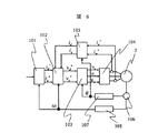
図6は図1の回転電機の制御ブロック図を示したものである。
【0039】
まず、タービンコントローラ及び単独に設置しているセンサからの情報(圧縮機圧力,ガス温度,運転モード,燃料ガススロットル開度etc )、および永久磁石形同期回転電機2の回転数を基に、運転判断部101が永久磁石形同期回転電機2の運転動作を判断して電流指令値を出力する。運転判断部101から出力された電流指令値は、現在の永久磁石形同期回転電機2の電流値との差分に対して非干渉制御等を行っている電流制御ブロック102に入力する。
【0040】
電流制御ブロック102からの出力は回転座標変換部103で3相の交流に変換され、PWMインバータ主回路104を介して永久磁石形同期回転電機2を制御する。また、永久磁石形同期回転電機2の各相の電流(少なくとも2相の電流)および回転数(タービン回転数でもよい。また変速機がある場合にはタービン回転数の逓倍した値を用いても良い。)を検出し、各相の電流は2軸変換ブロック105で、2軸電流に変換し、電流指令値にフィードバックしている。また、回転数,磁極位置らは検出器106で検出され、磁極位置変換部107と速度変換部108らを通して各制御ブロックにフィードバックされる。
【0041】
尚、図6における実施例では、回転電機2の位置・速度センサ、ならびに回転電機の電流センサがある場合のものを示したが、これらの一部のセンサを排除し、センサレスにより回転電機2を駆動するタイプの制御構成のものでも、同様に実施可能である。
【0042】
また、本発明の永久磁石形同期回転電機は、運転状況に応じて第1回転子と第2回転子の両磁極中心を揃えたり、ずらせたりすることになるので、前記第1の界磁用磁石と第2の界磁用磁石との合成磁極位置のずれに応じて前記電力変換器を制御するコントローラによる電流供給の進角を補正する機能を持つ。
【0043】
電流供給の進角を補正する実施例について述べる。
【0044】
前記第1の界磁用磁石はシャフトに固定し、前記第2の界磁用磁石はシャフトと可動自在に結合すると共に、シャフトにはボルトのネジ部と第2の界磁用磁石の内周側にはナット部になりお互いにネジの機能を持たせると、第2の界磁用磁石は回転しながら軸方向に移動する。
【0045】
運転状況に応じて第1回転子と第2回転子の磁極中心が一致したり、ずれたりする場合の回転角と軸方向変位量の関係を図13に示す。
【0046】
図13において、第2回転子の回転角θと軸方向変位量ΔLは比例関係であり、変位測定器64を用いて軸方向変位量ΔLを測定し、電力変換器のコントローラにフィードバックされ第1の界磁用磁石と第2の界磁用磁石との合成磁極位置のずれ角に換算した値として、電流供給の進角を補正する最適制御に用いる。
【0047】
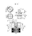
図7は本発明の他の実施形態をなす回転電機を示す。
【0048】
前記第1回転子20Aはシャフト22に固定し、前記第2回転子20Bはシャフト22と可動自在に結合すると共に、シャフトの一部にはボルトのネジ部23Aと第2の界磁用磁石の内周側にスリーブ41を固定し、かつスリーブ41の内側にナット部23Bを固定したものを一体化すれば、シャフト22に対して第2回転子20Bはボルトのネジ部からナット部が外れる方向に第1回転子20Aと第2回転子20Bの間の間隔が広がりながら回転する。
【0049】
第2の界磁用磁石の内周側とシャフト22間にはわずかな遊びがあることで、回転と共に第2の界磁用磁石の内周側とシャフト22間に鎖交磁束変化が生じると、電食等の障害があるが、前記スリーブ41は鉄より電気抵抗率が高い非磁性体を用いることで、第2の界磁用磁石の内周側とシャフト22間には磁気的にも、電気的にも絶縁を行う効果がある。
【0050】
前記第2の界磁用磁石と前記シャフト間には回転運動と往復運動及び複合運動を案内出来るようにスリーブ41の内側に支持機構40A,40Bを備えた。
【0051】
第2回転子20Bはシャフトの一部にボルトのネジ部23Aを設け、これとお互いにネジの機能を持たせて、第2の界磁用磁石の側面から離れたところには移動可能なストッパー24を設ける。ストッパー24とシャフト間、ストッパーと第2回転子20Bの側面間には回転運動と往復運動及び複合運動を案内出来るように支持機構42,47を設ける。支持機構42はスラスト軸受の機能を持ち、支持機構47はラジアル軸受でありながら回転運動と往復運動及び複合運動を案内する機能を持つ。
【0052】
さらに、ばね48を設けることで、支持機構42はスラスト軸受としてその機能が向上する効果がある。
【0053】
ストッパー24はシャフトと平行に移動可能なサーボ機構の一例として電磁クラッチについて述べる。
【0054】
電磁クラッチの構成は、ヨーク44にコイル46が巻かれて、ストッパー24は可動鉄心の機能を兼用することで良い。ヨーク44とコイル46は回転電機のフレーム49、若しくは車体の一部に(図に示せず)固定し、ヨーク44とストッパー24の間にばね45を備えて励磁遮断時の復帰装置の機能を持つ。回転電機のフレーム49とシャフト22の間には軸受50で支える。
【0055】
図7はコイル46に無励磁状態の概略であり、図8はコイル46に励磁状態の概略を示す。
【0056】
コイル46を励磁することでヨーク44は強力な電磁石となり、可動鉄心の機能を兼用するストッパー24を吸引する。
【0057】
ここに示した電磁クラッチはストッパー24をシャフトと平行に可変可能なサーボ機構の一例であり、油圧アクチュエータ,回転機とボールネジなどによる直線駆動装置,リニアモータなどを用いることで、より細かなストッパーの位置決めが可能である。
【0058】
図9は第2回転子20Bの内側に固定されるスリーブ41の一例を示す。
【0059】
それらの固定方法の一つとして、第2回転子20Bとスリーブ41からなる2つの部品の接する面のお互いに凸凹を設けて固定した。また、シャフト22に固定した第1回転子20Aとシャフト22と分離した第2回転子20Bの内側違いの概略を示す。
【0060】
図10は本発明の他の実施例を示す。
【0061】
前記第1の界磁用磁石と前記第2の界磁用磁石が接する前記第1の界磁用磁石側面に凹部53を設け、前記第2の界磁用磁石には前記スリーブの機能を兼ねた突起部54を設けた構造である。突起部54はスリーブ41と一体ものでも良いし、第2回転子20Bと一体ものでも良い。よって、スリーブ41の十分なスペースが確保出来、ばね48,支持機構40A,40B,ナット部23Bらを有効に配置することで、第2回転子20Bの軸長積厚が薄い回転電機に有効な手法の一つである。
【0062】
図11は本発明の他の実施例を示す。
【0063】
図11に示す基本構成要素は図7と同じであるが、電磁クラッチに相当する一部を変更した一例である。図11はコイル46が励磁状態であり、励磁遮断時はばね45によりヨーク44とストッパー24は切り離れる。また、第2回転子
20Bにトルクが加わるボルトのネジ部23Aとナット部23Bの相互作用によるネジの機能により推力が得られる特性を持つ。よって、ネジとトルクの相互関係でストッパー24を押し出す推力が加われば、コイル46の励磁を遮断するとストッパー24はヨーク44と切り離れる。ヨーク44はアーム52を介してフレーム49、若しくは台車本体の一部に(図に示せず)固定される。
【0064】
図11に示す電磁クラッチは、図7,図8の説明と同じくストッパー24をシャフトと平行に可変可能なサーボ機構の一例であり、油圧アクチュエータ,回転機とボールネジなどによる直線駆動装置,リニアモータなどを用いることで、より細かなストッパー24の位置決めが可能である。
【0065】
勿論、各図に示した各々の構成要素は様々な方法で組合せることが可能であり、用途に合わせて加えたり、取り外すことは言うまでもない。
【0066】
図12は本発明の他の実施形態をなす回転電機を示す。
【0067】
本発明の回転電機の特徴として、第1回転子20Aはシャフト22に対してしっかり固定されているのに対して、第2回転子20Bはシャフト22に対して自由度を持つことになる。従って、第2回転子20Bとシャフト22間にはわずかな機械的な寸法の遊びがあり、大きなトルクや遠心力などが加わると偏心することもあり得る。よって、第1の界磁用磁石を有する第1回転子20Aと前記固定子間のエアギャップGap1より第2の界磁用磁石を有する第2回転子20Bと前記固定子間のエアギャップGap2の方が大きくしたことで、偏心による第2回転子20Bと前記固定子との機械的な接続を省く効果がある。
【0068】
図15は本発明の他の実施形態をなす回転電機を示す。
【0069】
本発明の回転電機の特徴として、第2回転子20Bの外周側の長さより内周側の長さを短くし、第2回転子20B内側にストッパー24とサーボ機構(ストッパー駆動用アクチュエータ)25を備えた構造である。よって、ストッパー24とサーボ機構25による回転子全体の軸方向長さを押さえる効果がある。
【0070】
以上の本発明の説明では、4極機を対象に述べたが、2極機、又は、6極機以上に適用出来る事は言うまでもない。一例として、図14には本発明を8極機に適用した場合の永久磁石形同期回転電機の回転子概略図を示す。また、回転子においては埋め込み磁石形でも、表面磁石形でも適用出来る事は言うまでもない。
【0071】
図16に本発明の他の実施形態をなす回転電機を示す。
【0072】
図16は、一次巻線を有する固定子と界磁用磁石とシャフトとを有する回転子からなる回転電機において、前記界磁用磁石は、回転方向に順次異なった極性の磁極が並んでいる第1の界磁用磁石と回転方向に順次異なった極性の磁極が並んでいる第2の界磁用磁石を有し、両方の界磁用磁石は軸方向と回転方向に変位する機構を有することを特徴とする回転電機を示す。
【0073】
図11に示す前記回転電機は、一方の界磁用磁石が他方の界磁用磁石に対して変位する機構は、一方の界磁用磁石はシャフトに固定し、他方の界磁用磁石はシャフトとは可動自在にする構造であったが、図16に示す前記回転電機は両方の界磁用磁石は軸方向と回転方向に変位する機構を有することが大きな違いである。
【0074】
図16において、両方の界磁用磁石の間には中央ストッパー64をシャフト
22の備え、両方の界磁用磁石の左右変位を抑える機能を持つ。これらの動きを図3と図4に示すようにボルトとナットに対応した例を図18に示す。
【0075】
図18において、図18の(1)に示すように左右両方のナットが中央ストッパー64を挟んで同磁極で揃っているが、左右両方のナットに同じ方向のトルクが加わると片方のナットは外側に外れて行く。
【0076】
よって、行きと帰りの回転方向が反対になる回転電機を用いる鉄道車両システムにおいて、電気車の発進等の低回転領域における高トルク特性が要求される場合は、図18の(1)に示すように左右両方の界磁用磁石を強制的に揃え、高回転領域において高出力特性が要求される場合は、図18の(2)(3)に示すように左右両方のストッパー24を必要に応じて可変可能にすれば、両方の界磁用磁石による合成磁界が変化することになり、弱め界磁効果が得られる。
【0077】
図17に本発明の他の実施形態をなす回転電機を示す。
【0078】
図17は、回転方向に順次異なった極性の磁極が並んでいる第1の界磁用磁石と回転方向に順次異なった極性の磁極が並んでいる第2の界磁用磁石を有し、両方の界磁用磁石は軸方向と回転方向に変位する機構を有し、前記第1の界磁用磁石と前記第2の界磁用磁石との間に回転方向に順次異なった極性の磁極が並んでいる第3の界磁用磁石を有することを特徴とする回転電機を示す。基本的な構造は図16に示す構造にして、更に回転子中央部に第3の界磁用磁石20Cをシャフト22に固定した例である。図16において、前記第1の界磁用磁石と前記第2の界磁用磁石との軸方向幅は同じくする。
【0079】
図16と図18とは同じく、図17の回転子部をボルトとナットに対応した例を図19に示し、基本的な動作原理は図18と同様である。
【0080】
図16から図19において、前記第1の界磁用磁石と前記第2の界磁用磁石とは軸方向と回転方向に変位する機構は、前記第1の界磁用磁石と前記第2の界磁用磁石はシャフトとは可動自在にすると共に、シャフトには同一方向のボルトのネジ部を有する。前記シャフトの前記ネジ部に対して、前記第1の界磁用磁石と前記第2の界磁用磁石の内周側にはナット部になりお互いにネジの機能を持たせたことを特徴とする回転電機である。
【0081】
図20と図21に本発明の他の実施形態をなす回転電機を示す。
【0082】
図20と図21は、本発明の回転電機の回転方向が同じである場合、車軸(出力軸)の回転方向を切り替える機構の一例であり、出力軸の回転方向を切り替える機構としては、回転を反転させるギア93とクラッチ90を有する。このような機構を用いることで、鉄道車両のように行きと帰りの車軸84の回転方向が反対になる場合、本発明の回転電機の回転方向を同じにした一例である。
【0083】
また、図21は車軸84の回転方向が同じの場合、本発明の回転電機の回転方向を反対にすれば、回転子に備えた両方の界磁用磁石の合成磁界を変化することができる。
【0084】
【発明の効果】
本発明の永久磁石形同期回転電機は第1の界磁用磁石と第2の界磁用磁石の磁極中心を変化させるという構成により、固定子磁極と対向する永久磁石による有効磁束量を可変出来るという効果があり、広範囲可変速搬送システムの回転電機に適している。
【図面の簡単な説明】
【図1】本発明の一実施形態をなす回転電機と鉄道車両とのレイアウト図を示す。
【図2】図1の回転電機の全体概略を示す。
【図3】図1の回転電機の回転子同磁極中心が揃った場合概略を示す。
【図4】図1の回転電機の回転子同磁極中心がずれた場合概略を示す。
【図5】図1の回転電機の回転角速度に対する諸特性を示す。
【図6】図1の回転電機の制御ブロック図を示す。
【図7】本発明の他の実施形態をなす回転電機を示す(アクチュエータOFF状態)。
【図8】本発明の他の実施形態をなす回転電機を示す(アクチュエータON状態)。
【図9】本発明の他の実施形態をなす回転電機の回転子の内側を示す。
【図10】本発明の他の実施形態をなす回転電機の回転子の内側を示す。
【図11】本発明の他の実施形態をなす回転電機を示す(アクチュエータON状態)。
【図12】本発明の他の実施形態をなす回転電機の回転子概略図を示す(Gapの差を付ける)。
【図13】本発明の他の実施形態をなす回転電機の軸方向変位測定の概略図を示す。
【図14】本発明の他の実施形態をなす回転電機の回転子概略図を示す(8極機に適用した場合)。
【図15】本発明の他の実施形態をなす回転電機の回転子概略図を示す(ストッパーを第2回転子の内側に備える)。
【図16】本発明の他の実施形態をなす回転電機を示す(両方の界磁用磁石は軸方向と回転方向に変位する機構を有する構造)。
【図17】本発明の他の実施形態をなす回転電機を示す(第1と第2と第3の界磁用磁石を有する構造)。
【図18】図16の回転電機の補足説明を示す。
【図19】図17の回転電機の補足説明を示す。本発明の他の実施形態をなす回転電機を示す。
【図20】本発明の他の実施形態をなす回転電機を示す。
【図21】本発明の他の実施形態をなす回転電機を示す。
【符号の説明】
2…回転電機、4…電力変換器、10…固定子鉄心、11…電機子巻線、13…ハウジング、20…回転子、20A…第1回転子、20B…第2回転子、21…永久磁石、21A…第1回転子永久磁石、21B…第2回転子永久磁石、22…シャフト、23…ネジ、24…ストッパー、25…ストッパー駆動用アクチュエータ、101…運転判断部、102…電流制御、103…回転座標変換部、104…PWMインバータ主回路、105…2軸変換部。[0001]
BACKGROUND OF THE INVENTION
The present invention relates to a rotating electrical machine using a permanent magnet as a field, and more particularly to a rotating electrical machine that drives and regenerates a transport system and a control method thereof.
[0002]
[Prior art]
In the permanent magnet rotating electrical machine according to the prior art, the induced electromotive force E is determined by the constant magnetic flux Φ generated by the permanent magnet disposed in the rotor and the rotational angular velocity ω of the rotating electrical machine. That is, when the rotational angular velocity ω (number of rotations) of the rotating electrical machine increases, the induced electromotive force of the rotating electrical machine increases in proportion.
[0003]
Therefore, high torque can be obtained in the low speed region, but since the variable speed range of the rotational speed is narrow, it is difficult to operate in the high speed region, but the high speed operation region is widened by field weakening control technology.
[0004]
Japanese Patent Laid-Open No. 2000-155262 uses a mechanism using centrifugal force by using a spring and a governor as a field weakening method for a magnetic flux generated by a permanent magnet.
[0005]
[Problems to be solved by the invention]
Extending the high-speed operation range by the field weakening control technology described in the prior art has a limit due to heat generation due to field weakening current and reduction in efficiency.
[0006]
In the method according to Japanese Patent Laid-Open No. 2000-155262, the structure of the spring and the governor is complicated.
[0007]
The present invention provides a rotating electrical machine capable of weakening the magnetic field generated by a permanent magnet with a simple structure. Further, the present invention provides a high torque characteristic in a low rotation region such as a start of a conveyance system, and a high output in a high rotation region. It is an object of the present invention to provide a transport system including a permanent magnet type rotating electrical machine capable of obtaining characteristics.
[0008]
[Means for Solving the Problems]
According to the present invention, in a rotating electrical machine, a first and second field magnets configured by arranging a stator having windings and poles having different polarities sequentially in a rotating direction are provided on a rotating shaft. And the first and second field magnets have a rotor arranged with respect to the stator so as to face the magnetic poles of the stator, and the first and second field magnets have magnetism. The first and second field magnets are configured to be displaceable in the axial direction and the rotational direction of the rotating shaft in accordance with the acting force and the direction of the torque generated in the rotor. According to the present invention, in the rotating electric machine, first to third field magnets configured by arranging a stator having windings and poles having different polarities in the rotation direction are provided on the rotating shaft. A first to third field magnet having a rotor arranged with respect to the stator so that the first to third field magnets face the magnetic poles of the stator. The first and second field magnets positioned at both ends of the third field magnet fixed on the rotating shaft according to the magnetic acting force of the rotor and the direction of the torque generated in the rotor It is comprised so that it can displace in the axial direction and rotational direction of this.
[0010]
The present invention relates to a carriage having wheels, a power source for the carriage, a rotating electrical machine that transmits power to the wheel axle, a current collector that takes power into the carriage from outside, and a rotation A rotating electric machine comprising: a stator having windings; and first and second field magnets configured by sequentially arranging ones having different polarities in the rotation direction. The first and second field magnets are provided on the rotary shaft, and have a rotor disposed with respect to the stator so as to face the magnetic poles of the stator, In accordance with the magnetic acting force of the first and second field magnets and the direction of the torque generated in the rotor, the first field magnet has an axis of rotation shaft relative to the second field magnet. It is configured to be able to be displaced in the direction and the rotational direction. The present invention also relates to a carriage having wheels, a power source for the carriage, a rotating electrical machine that transmits power to the axle of the wheel, and a current collector that takes power into the carriage from the outside in the transport system system. And a power converter for controlling the electric power of the rotating electrical machine. The rotating electrical machine includes a stator having windings and first and second field magnets configured by sequentially arranging ones having different polarities in the rotation direction. And a rotor disposed on the stator so that the first and second field magnets are opposed to the magnetic poles of the stator. The first and second field magnets rotate in the axial direction and the rotation direction of the rotation axis according to the magnetic acting force of the first and second field magnets and the direction of the torque generated in the rotor. It is configured so that it can be displaced. Furthermore, the present invention relates to a carriage having wheels, a power source for the carriage, a rotating electrical machine that transmits power to the wheel axle, and a current collector that takes power into the carriage from the outside in the transport system. And a power converter for controlling the electric power of the rotating electric machine, the rotating electric machine for the first to third field elements configured by arranging a stator having a winding and poles having different polarities in the rotation direction in sequence. A magnet is provided on the rotating shaft, and the first to third field magnets have a rotor arranged with respect to the stator so as to face the magnetic pole of the stator. In accordance with the magnetic acting force of the first to third field magnets and the direction of the torque generated in the rotor, it is positioned at both ends of the third field magnet fixed on the rotating shaft. The first and second field magnets can be displaced in the axial direction and the rotation direction of the rotation shaft. Characterized in that it is one that is configured.
[0011]
DETAILED DESCRIPTION OF THE INVENTION
Embodiments of the present invention will be described below.
[0012]
FIG. 1 shows an arrangement layout of the permanent magnet type synchronous rotating electric machine of this embodiment.
[0013]
There are various transport systems using a rotating electrical machine as a power source. FIG. 1 shows an example of a railway vehicle system as an example.
[0014]
1 is a railway vehicle system that includes a
[0015]
Here, the electric vehicle is a railway vehicle that uses electricity as power. Further, in a transport system in a broad sense including a railway vehicle system, it has a meaning corresponding to a carriage.
[0016]
In addition, the current collector is a device that takes power into the electric car (or truck) from the outside of the vehicle. The overhead wire type 86 is a pantograph, the third rail type is a current collector, and is not in contact with the transportation system in the factory. It is also a current collector.
[0017]
The rotating
[0018]
FIG. 2 shows an outline when the magnetic pole center of the rotor of the rotating electrical machine of FIG. 1 is shifted. An armature winding 11 is wound around the
[0019]
The permanent magnet embedded
[0020]
In the
[0021]
The inner diameter side of the
[0022]
Further, a
[0023]
It will be described that the effective magnetic flux amount of the permanent magnet is changed according to the direction of torque by adopting the above structure.
[0024]
Basically, in a rotating electrical machine that uses an armature winding for the stator and a permanent magnet for the rotor, if the direction of rotation of the rotor is the same when acting as a motor and regenerative (or generator) The direction of torque received by the rotor when working as an electric motor and when working as a regenerative (or generator) is opposite.
[0025]
Also, when working with the same electric motor, if the opposite rotational direction of the rotor, also the opposite torque direction. Similarly, when working with the same regeneration (or generator), if the opposite rotational direction of the rotor, also the opposite torque direction.
[0026]
The basic theory based on the rotation direction and the torque direction described above is applied to the rotating electrical machine according to the embodiment of the present invention as follows.
[0027]
As shown in FIG. 3, the same magnetic poles of the
[0028]
Next, when acting as a high output characteristic in the high rotation region, the
[0029]
FIG. 4 shows an outline of a state where the center of the magnetic pole is shifted while the interval between the
[0030]
3 and FIG. 4 are diagrams related to the
[0031]
The effect | action of the induced electromotive force by the rotary electric machine of this invention is demonstrated.
[0032]
FIG. 5 shows the characteristics of the effective magnetic flux, induced electromotive force, and terminal voltage with respect to the rotational angular velocity of the permanent magnet type synchronous rotating electric machine.
[0033]
The induced electromotive force E of the permanent magnet type synchronous rotating electric machine is determined by the magnetic flux Φ generated by the permanent magnet and the rotational angular velocity ω of the rotating electric machine. That is, as shown in FIG. 5A, if the magnetic flux Φ1 generated by the permanent magnet arranged in the rotor is constant, the induced electromotive force E1 of the rotating electrical machine is proportional when the rotational angular velocity ω (the number of rotations) increases. Then rise. However, there are limitations on the power supply terminal voltage and capacity of the
[0034]
Since the induced electromotive force rises in proportion to the rotational angular velocity, it is necessary to increase the current for field weakening control. Therefore, it is necessary to flow a large current through the coil that is the primary conductor, which naturally increases the heat generated by the coil. . For this reason, there is a possibility that the efficiency of the rotating electric machine in the high rotation region is reduced, the permanent magnet is demagnetized due to heat generation exceeding the cooling capacity, and the like.
[0035]
For example, as shown in FIG. 5A, when the magnetic flux Φ1 generated by the permanent magnet is changed to the magnetic flux Φ2 at a certain rotational angular velocity ω1 (rotational speed), the induced electromotive force E2 characteristic from the induced electromotive force E1 of the rotating electrical machine. It is possible to limit the maximum value of the induced electromotive force by changing to.
[0036]
Similarly, FIG. 5B schematically shows that the induced electromotive force E can be kept constant if the magnetic flux Φ changes more finely according to the rotational angular velocity ω (the number of rotations).
[0037]
Furthermore, as one example of means for obtaining the characteristics shown in FIG. 5B, the first field magnet is fixed to a shaft, and the second field magnet is movable with respect to the shaft. with binding to, screws of the bolt shaft and the inner peripheral side of the second field magnet is connected to have a function of the screw to each other becomes the nut portion, the side surface of the second field magnet It is possible to use a rotating electrical machine having a servo mechanism that is provided with a stopper at a position remote from the shaft and the stopper can be changed in parallel with the shaft according to the rotational speed.
[0038]
FIG. 6 shows a control block diagram of the rotating electrical machine of FIG.
[0039]
First, based on information (compressor pressure, gas temperature, operation mode, fuel gas throttle opening etc.) from the turbine controller and the sensor installed alone, and the number of rotations of the permanent magnet type synchronous rotating
[0040]
The output from the
[0041]
In the embodiment shown in FIG. 6, the position / speed sensor of the rotating
[0042]
In the permanent magnet type synchronous rotating electric machine according to the present invention, both the magnetic pole centers of the first rotor and the second rotor are aligned or shifted according to the operating condition. It has a function of correcting the advance angle of the current supply by the controller that controls the power converter in accordance with the deviation of the composite magnetic pole position between the magnet and the second field magnet.
[0043]
An embodiment for correcting the advance angle of the current supply will be described.
[0044]
The first field magnet is fixed to a shaft, the second field magnet is movably coupled to the shaft, and a screw portion of a bolt and an inner periphery of the second field magnet are connected to the shaft. When the nut portion is provided on the side and the functions of the screws are given to each other, the second field magnet moves in the axial direction while rotating.
[0045]
FIG. 13 shows the relationship between the rotation angle and the amount of axial displacement when the magnetic pole centers of the first and second rotors match or deviate depending on the operating conditions.
[0046]
In FIG. 13, the rotation angle θ of the second rotor and the axial displacement amount ΔL are in a proportional relationship, and the axial displacement amount ΔL is measured using the
[0047]
FIG. 7 shows a rotating electrical machine according to another embodiment of the present invention.
[0048]
The
[0049]
When there is a slight play between the inner peripheral side of the second field magnet and the
[0050]
Between the second field magnet and the shaft,
[0051]
The
[0052]
Further, the provision of the
[0053]
An electromagnetic clutch will be described as an example of a servo mechanism in which the
[0054]
The electromagnetic clutch may be configured such that the
[0055]
7 shows an outline of the
[0056]
By exciting the
[0057]
The electromagnetic clutch shown here is an example of a servo mechanism in which the
[0058]
FIG. 9 shows an example of a
[0059]
As one of those fixing methods, the surfaces where the two parts including the
[0060]
FIG. 10 shows another embodiment of the present invention.
[0061]
A
[0062]
FIG. 11 shows another embodiment of the present invention.
[0063]
The basic components shown in FIG. 11 are the same as those shown in FIG. 7, but an example in which a part corresponding to the electromagnetic clutch is changed. In FIG. 11, the
[0064]
The electromagnetic clutch shown in FIG. 11 is an example of a servo mechanism in which the
[0065]
Of course, each component shown in each figure can be combined in various ways, and it goes without saying that it is added or removed according to the application.
[0066]
FIG. 12 shows a rotating electrical machine according to another embodiment of the present invention.
[0067]
As a feature of the rotating electrical machine of the present invention, the
[0068]
FIG. 15 shows a rotating electrical machine according to another embodiment of the present invention.
[0069]
As a feature of the rotating electrical machine of the present invention, the length on the inner peripheral side is made shorter than the length on the outer peripheral side of the
[0070]
In the above description of the present invention, a 4-pole machine has been described, but it goes without saying that it can be applied to a 2-pole machine or a 6-pole machine or more. As an example, FIG. 14 shows a schematic view of a rotor of a permanent magnet type synchronous rotating electric machine when the present invention is applied to an 8-pole machine. Further, it goes without saying that the rotor can be applied to either an embedded magnet type or a surface magnet type.
[0071]
FIG. 16 shows a rotating electrical machine according to another embodiment of the present invention.
[0072]
FIG. 16 shows a rotating electrical machine composed of a stator having a primary winding, a field magnet, and a rotor having a shaft, wherein the field magnets are arranged with magnetic poles of different polarities sequentially in the rotation direction. 1 field magnet and a second field magnet in which magnetic poles of different polarities are sequentially arranged in the rotation direction, both field magnets having a mechanism that is displaced in the axial direction and the rotation direction. The rotary electric machine characterized by this is shown.
[0073]
The rotary electric machine shown in FIG. 11 has a mechanism in which one field magnet is displaced with respect to the other field magnet, one field magnet is fixed to the shaft, and the other field magnet is the shaft. However, the rotating electrical machine shown in FIG. 16 has a major difference in that both field magnets have a mechanism for displacing in the axial direction and the rotational direction.
[0074]
In FIG. 16, a
[0075]
In FIG. 18, both the left and right nuts are aligned with the same magnetic pole across the
[0076]
Therefore, in a railway vehicle system that uses a rotating electrical machine in which the rotation direction of the going and returning directions is opposite, when high torque characteristics in a low rotation region such as start of an electric vehicle are required, as shown in (1) of FIG. If both the left and right field magnets are forcibly aligned and high output characteristics are required in the high rotation range, both left and
[0077]
FIG. 17 shows a rotating electrical machine according to another embodiment of the present invention.
[0078]
FIG. 17 includes a first field magnet in which magnetic poles of different polarities are arranged in the rotation direction and a second field magnet in which magnetic poles of different polarities are arranged in the rotation direction. The field magnet has a mechanism for displacement in the axial direction and the rotational direction, and magnetic poles having different polarities in the rotational direction are sequentially provided between the first field magnet and the second field magnet. The rotary electric machine characterized by having the 3rd field magnet arranged in a line is shown. The basic structure is an example in which the structure shown in FIG. 16 is used, and a
[0079]
Similarly to FIGS. 16 and 18, FIG. 19 shows an example in which the rotor portion of FIG. 17 corresponds to a bolt and a nut, and the basic operation principle is the same as FIG.
[0080]
In FIG. 16 to FIG. 19, the mechanism for displacing the first field magnet and the second field magnet in the axial direction and the rotational direction includes the first field magnet and the second field magnet. The field magnet is movable with respect to the shaft, and the shaft has a screw portion of a bolt in the same direction. With respect to the screw portion of the shaft, the first field magnet and the second field magnet have nut portions on the inner peripheral side thereof, and have a screw function with each other. Rotating electric machine.
[0081]
20 and 21 show a rotating electrical machine according to another embodiment of the present invention.
[0082]
20 and 21 are examples of a mechanism for switching the rotation direction of the axle (output shaft) when the rotation direction of the rotating electrical machine of the present invention is the same. A
[0083]
In FIG. 21, when the rotation direction of the
[0084]
【The invention's effect】
The permanent magnet type synchronous rotating electrical machine of the present invention can vary the effective magnetic flux amount by the permanent magnet facing the stator magnetic pole by changing the magnetic pole centers of the first field magnet and the second field magnet. It is suitable for rotating electrical machines in a wide range of variable speed conveyance systems.
[Brief description of the drawings]
FIG. 1 shows a layout diagram of a rotating electrical machine and a railway vehicle that constitute an embodiment of the present invention.
2 shows an overall outline of the rotating electrical machine of FIG.
FIG. 3 shows an outline when the magnetic pole centers of the rotor of the rotating electrical machine of FIG. 1 are aligned.
4 shows an outline when the magnetic pole center of the rotor of the rotating electrical machine in FIG. 1 is shifted. FIG.
5 shows various characteristics with respect to the rotational angular velocity of the rotating electrical machine of FIG. 1. FIG.
6 shows a control block diagram of the rotating electrical machine of FIG. 1. FIG.
FIG. 7 shows a rotating electrical machine according to another embodiment of the present invention (actuator OFF state).
FIG. 8 shows a rotating electrical machine according to another embodiment of the present invention (actuator ON state).
FIG. 9 shows the inside of a rotor of a rotating electrical machine that constitutes another embodiment of the present invention.
FIG. 10 shows the inside of a rotor of a rotating electrical machine that constitutes another embodiment of the present invention.
FIG. 11 shows a rotating electrical machine according to another embodiment of the present invention (actuator ON state).
FIG. 12 shows a schematic view of a rotor of a rotating electrical machine that constitutes another embodiment of the present invention (with a gap difference).
FIG. 13 shows a schematic diagram of axial displacement measurement of a rotating electrical machine that constitutes another embodiment of the present invention.
FIG. 14 is a schematic view of a rotor of a rotating electrical machine that constitutes another embodiment of the present invention (when applied to an 8-pole machine).
FIG. 15 is a schematic view of a rotor of a rotating electrical machine that constitutes another embodiment of the present invention (with a stopper provided inside the second rotor).
FIG. 16 shows a rotating electrical machine according to another embodiment of the present invention (both field magnets have a mechanism for displacement in the axial direction and the rotational direction).
FIG. 17 shows a rotating electrical machine according to another embodiment of the present invention (structure having first, second, and third field magnets).
18 shows a supplementary explanation of the rotating electrical machine of FIG.
FIG. 19 shows a supplementary explanation of the rotating electric machine of FIG. The rotary electric machine which makes other embodiment of this invention is shown.
FIG. 20 shows a rotating electrical machine according to another embodiment of the present invention.
FIG. 21 shows a rotating electrical machine according to another embodiment of the present invention.
[Explanation of symbols]
DESCRIPTION OF
Claims (24)
回転方向に順次異なった極性のものを並べて構成した第1及び第2の界磁用磁石が回転軸上に設けられたものであって、該第1及び第2の界磁用磁石が前記固定子の磁極に対向するように前記固定子に対して配置された回転子とを有し、
前記第1及び第2の界磁用磁石の磁気作用力と前記回転子に発生するトルクの方向とに応じて前記第1及び第2の界磁用磁石が前記回転軸の軸方向と回転方向に変位できるように構成されている
ことを特徴とする回転電機。A stator having windings;
The first and second field magnets are arranged on the rotating shaft, and the first and second field magnets are arranged on the rotating shaft. A rotor arranged with respect to the stator so as to face the magnetic pole of the child,
The first and second field magnets rotate in the axial direction and the rotation direction of the rotation shaft according to the magnetic acting force of the first and second field magnets and the direction of the torque generated in the rotor. A rotating electric machine characterized by being configured to be displaceable.
前記回転子が低速で一方向又は他方向に回転する場合、前記第1及び第2の界磁用磁石の磁極中心を並べた状態が保持され、
前記回転子が高速で一方向に回転する場合、前記第1の界磁用磁石が保持された状態で前記第2の界磁用磁石が前記第1の界磁用磁石に対して変位させられ、前記第1及び第2の界磁用磁石の磁極中心を並べた状態から前記第1及び第2の界磁用磁石の磁極中心がずらされ、
前記回転子が高速で他方向に回転する場合、前記第2の界磁用磁石が保持された状態で前記第1の界磁用磁石が前記第2の界磁用磁石に対して変位させられ、前記第1及び第2の界磁用磁石の磁極中心を並べた状態から前記第1及び第2の界磁用磁石の磁極中心がずらされる
ことを特徴とする回転電機。In the rotating electrical machine according to claim 1,
When the rotor rotates in one direction or the other direction at a low speed, the state in which the magnetic pole centers of the first and second field magnets are aligned is maintained,
When the rotor rotates in one direction at a high speed, the second field magnet is displaced with respect to the first field magnet while the first field magnet is held. The magnetic pole centers of the first and second field magnets are shifted from the state in which the magnetic pole centers of the first and second field magnets are aligned,
When the rotor rotates in the other direction at a high speed, the first field magnet is displaced with respect to the second field magnet while the second field magnet is held. A rotating electrical machine characterized in that the magnetic pole centers of the first and second field magnets are shifted from the state in which the magnetic pole centers of the first and second field magnets are arranged.
前記第1及び第2の界磁用磁石の磁気作用力と前記回転子に発生するトルクの方向とに応じて前記第1及び第2の界磁用磁石を前記回転軸に対してその軸方向と回転方向に可動させる機構と、
前記第1及び第2の界磁用磁石の可動を抑制する機構とを有する
ことを特徴とする回転電機。In the rotating electrical machine according to claim 1,
An axial direction of the first and second field magnets relative to the rotation axis according to a magnetic acting force of the first and second field magnets and a direction of a torque generated in the rotor. And a mechanism for moving in the rotation direction,
A rotating electrical machine having a mechanism for suppressing movement of the first and second field magnets.
前記可動機構は、
前記第1及び第2の界磁用磁石が前記回転軸に対して可動自在なように前記第1及び第2の界磁用磁石と前記回転軸とを結合するものであって、
前記第1及び第2の界磁用磁石に設けられたナット機構と、前記回転軸に設けられたボルト機構から構成されたネジ機構である
ことを特徴とする回転電機。In the rotating electrical machine according to claim 3,
The movable mechanism is
The first and second field magnets and the rotating shaft are coupled so that the first and second field magnets are movable with respect to the rotating shaft,
A rotating electrical machine comprising a nut mechanism provided on the first and second field magnets and a screw mechanism provided on a rotating shaft.
前記可動抑制機構は、
前記第1の界磁用磁石と前記第2の界磁用磁石との間の前記回転軸上に設けられたものと、
前記第1の界磁用磁石の前記第2の界磁用磁石側とは反対側及び前記第2の界磁用磁石の前記第1の界磁用磁石側とは反対側に設けられ、前記回転軸に沿って移動可能に構成されたものとを有する
ことを特徴とする回転電機。In the rotating electrical machine according to claim 3,
The movable suppression mechanism is
Provided on the rotating shaft between the first field magnet and the second field magnet;
Provided on the opposite side of the first field magnet to the second field magnet side and on the opposite side of the second field magnet to the first field magnet side, A rotating electrical machine having a structure that is movable along a rotating shaft.
回転方向に順次異なった極性のものを並べて構成した第1乃至第3の界磁用磁石が回転軸上に設けられたものであって、該第1乃至第3の界磁用磁石が前記固定子の磁極に対向するように前記固定子に対して配置された回転子とを有し、
前記第1乃至第3の界磁用磁石の磁気作用力と前記回転子に発生するトルクの方向とに応じて、前記回転軸上に固定された前記第3の界磁用磁石の両端に位置する前記第1及び第2の界磁用磁石が前記回転軸の軸方向と回転方向に変位できるように構成されている
ことを特徴とする回転電機。A stator having windings;
First to third field magnets configured by sequentially arranging ones having different polarities in the rotation direction are provided on a rotating shaft, and the first to third field magnets are fixed. A rotor arranged with respect to the stator so as to face the magnetic pole of the child,
Positioned at both ends of the third field magnet fixed on the rotating shaft according to the magnetic acting force of the first to third field magnets and the direction of torque generated in the rotor. The rotating electric machine is configured such that the first and second field magnets can be displaced in an axial direction and a rotational direction of the rotating shaft.
前記回転子が低速で一方向又は他方向に回転する場合、前記第1乃至第3の界磁用磁石の磁極中心を並べた状態が保持され、
前記回転子が高速で一方向に回転する場合、前記第1及び第3の界磁用磁石の磁極中心を並べた状態で前記第2の界磁用磁石が前記第3の界磁用磁石に対して変位させられ、前記第1乃至第3の界磁用磁石の磁極中心を並べた状態から前記第2及び第3の界磁用磁石の磁極中心がずらされ、
前記回転子が高速で他方向に回転する場合、前記第2及び第3の界磁用磁石の磁極中心を並べた状態で前記第1の界磁用磁石が前記第3の界磁用磁石に対して変位させられ、前記第1乃至第3の界磁用磁石の磁極中心を並べた状態から前記第1及び第3の界磁用磁石の磁極中心がずらされる
ことを特徴とする回転電機。In the rotating electrical machine according to claim 6,
When the rotor rotates in one direction or the other direction at a low speed, the state in which the magnetic pole centers of the first to third field magnets are arranged is maintained,
When the rotor rotates in one direction at high speed, the second field magnet becomes the third field magnet with the magnetic pole centers of the first and third field magnets aligned. The magnetic pole centers of the second and third field magnets are shifted from the state in which the magnetic pole centers of the first to third field magnets are arranged.
When the rotor rotates in the other direction at high speed, the first field magnet becomes the third field magnet with the magnetic pole centers of the second and third field magnets aligned. A rotating electrical machine characterized in that the magnetic pole centers of the first and third field magnets are displaced from the state in which the magnetic pole centers of the first to third field magnets are aligned.
前記第1乃至第3の界磁用磁石の磁気作用力と前記回転子に発生するトルクの方向とに応じて前記第1及び第2の界磁用磁石を前記回転軸に対してその軸方向と回転方向に可動させる機構と、
前記第1及び第2の界磁用磁石の可動を抑制する機構とを有する
ことを特徴とする回転電機。In the rotating electrical machine according to claim 6,
An axial direction of the first and second field magnets with respect to the rotation axis in accordance with a magnetic acting force of the first to third field magnets and a direction of a torque generated in the rotor. And a mechanism for moving in the rotation direction,
A rotating electrical machine having a mechanism for suppressing movement of the first and second field magnets.
前記可動機構は、
前記第1及び第2の界磁用磁石が前記回転軸に対して可動自在なように前記第1及び第2の界磁用磁石と前記回転軸とを結合するものであって、
前記第1及び第2の界磁用磁石に設けられたナット機構と、前記回転軸に設けられたボルト機構から構成されたネジ機構である
ことを特徴とする回転電機。The rotating electrical machine according to claim 8,
The movable mechanism is
The first and second field magnets and the rotating shaft are coupled so that the first and second field magnets are movable with respect to the rotating shaft,
A rotating electrical machine comprising a nut mechanism provided on the first and second field magnets and a screw mechanism provided on a rotating shaft.
前記可動抑制機構は、前記第1の界磁用磁石の前記第2の界磁用磁石側とは反対側及び前記第2の界磁用磁石の前記第1の界磁用磁石側とは反対側に設けられ、前記回転軸に沿って移動可能に構成されたものである
ことを特徴とする回転電機。The rotating electrical machine according to claim 8,
The movable suppression mechanism is opposite to the second field magnet side of the first field magnet and opposite to the first field magnet side of the second field magnet. A rotating electrical machine that is provided on a side and is configured to be movable along the rotating shaft.
前記巻線は、前記第1の界磁用磁石の変位或いは前記第2の界磁用磁石の変位に応じて進角が補正された電流の供給を受ける
ことを特徴とする回転電機。In the rotating electrical machine according to claim 1 or 6,
The rotating electrical machine is characterized in that the winding is supplied with a current whose advance angle is corrected in accordance with the displacement of the first field magnet or the displacement of the second field magnet.
前記第1及び第2の界磁用磁石と前記回転軸との間には、前記第1及び第2の界磁用磁石の運動を案内する支持機構が設けられている
ことを特徴とする回転電機。In the rotating electrical machine according to claim 1 or 6,
A rotation mechanism characterized in that a support mechanism for guiding the movement of the first and second field magnets is provided between the first and second field magnets and the rotating shaft. Electric.
前記第1及び第2の界磁用磁石は、前記回転軸と磁気的及び電気的に絶縁するスリーブを介して前記回転軸上に設けられている
ことを特徴とする回転電機。In the rotating electrical machine according to claim 1 or 6,
The rotating electric machine according to claim 1, wherein the first and second field magnets are provided on the rotating shaft via a sleeve that is magnetically and electrically insulated from the rotating shaft.
前記スリーブは、鉄より電気抵抗率が高い非磁性体である
ことを特徴とする回転電機。The rotating electrical machine according to claim 13,
The rotating electrical machine according to claim 1, wherein the sleeve is a non-magnetic material having a higher electrical resistivity than iron.
前記第1の界磁用磁石の前記第2の界磁用磁石側及び前記第2の界磁用磁石の前記第1の界磁用磁石側にばねが設けられており、
該ばねは前記第1及び第2の界磁用磁石の運動を案内する
ことを特徴とする回転電機。In the rotating electrical machine according to claim 5 or 10,
A spring is provided on the second field magnet side of the first field magnet and on the first field magnet side of the second field magnet,
The rotary electric machine is characterized in that the spring guides the movement of the first and second field magnets.
該台車の動力源であって、前記車輪の車軸に動力を伝達する回転電機と、
外部から前記台車内に電力を取り入れる集電装置と、
前記回転電機の電力を制御する電力変換器とを有し、
前記回転電機は、
巻線を有する固定子と、
回転方向に順次異なった極性のものを並べて構成した第1及び第2の界磁用磁石が回転軸上に設けられたものであって、該第1及び第2の界磁用磁石が前記固定子の磁極に対向するように前記固定子に対して配置された回転子とを有するものであり、
前記第1及び第2の界磁用磁石の磁気作用力と前記回転子に発生するトルクの方向とに応じて、前記第1の界磁用磁石が第2の界磁用磁石に対して前記回転軸の軸方向と回転方向に変位できるように構成されたものである
ことを特徴とする搬送システム。A carriage having wheels;
A rotating electric machine that is a power source of the carriage and transmits power to an axle of the wheel;
A current collector that takes power into the carriage from outside;
A power converter for controlling the power of the rotating electrical machine,
The rotating electric machine is
A stator having windings;
The first and second field magnets are arranged on the rotating shaft, and the first and second field magnets are arranged on the rotating shaft. A rotor arranged with respect to the stator so as to face the magnetic pole of the child,
In accordance with the magnetic acting force of the first and second field magnets and the direction of the torque generated in the rotor, the first field magnet moves the second field magnet with respect to the second field magnet. A transport system configured to be displaceable in an axial direction and a rotational direction of a rotary shaft.
前記台車が低速度領域にある場合、前記第1及び第2の界磁用磁石の磁極中心を並べた状態が保持され、
前記台車が高速度領域にある場合、前記第1の界磁用磁石が前記第2の界磁用磁石に対して変位させられ、前記第1及び第2の界磁用磁石の磁極中心がずれる
ことを特徴とする搬送システム。The transport system according to claim 16, wherein
When the carriage is in a low speed region, the state where the magnetic pole centers of the first and second field magnets are aligned is maintained,
When the carriage is in the high speed region, the first field magnet is displaced with respect to the second field magnet, and the magnetic pole centers of the first and second field magnets are shifted. A conveyance system characterized by that.
該台車の動力源であって、前記車輪の車軸に動力を伝達する回転電機と、
外部から前記台車内に電力を取り入れる集電装置と、
前記回転電機の電力を制御する電力変換器とを有し、
前記回転電機は、
巻線を有する固定子と、
回転方向に順次異なった極性のものを並べて構成した第1及び第2の界磁用磁石が回転軸上に設けられたものであって、該第1及び第2の界磁用磁石が前記固定子の磁極に対向するように前記固定子に対して配置された回転子とを有するものであり、
前記第1及び第2の界磁用磁石の磁気作用力と前記回転子に発生するトルクの方向とに応じて前記第1及び第2の界磁用磁石が前記回転軸の軸方向と回転方向に変位できるように構成されたものである
ことを特徴とする搬送システム。A carriage having wheels;
A rotating electric machine that is a power source of the carriage and transmits power to an axle of the wheel;
A current collector that takes power into the carriage from outside;
A power converter for controlling the power of the rotating electrical machine,
The rotating electric machine is
A stator having windings;
The first and second field magnets are arranged on the rotating shaft, and the first and second field magnets are arranged on the rotating shaft. A rotor arranged with respect to the stator so as to face the magnetic pole of the child,
The first and second field magnets rotate in the axial direction and the rotation direction of the rotation shaft according to the magnetic acting force of the first and second field magnets and the direction of the torque generated in the rotor. A conveyance system characterized by being configured to be displaceable.
前記台車が低速度領域にあって一方向又は他方向に進行している場合、前記第1及び第2の界磁用磁石の磁極中心を並べた状態が保持され、
前記台車が高速度領域にあって一方向に進行している場合、前記第1の界磁用磁石が保持された状態で前記第2の界磁用磁石が前記第1の界磁用磁石に対して変位させられ、前記第1及び第2の界磁用磁石の磁極中心を並べた状態から前記第1及び第2の界磁用磁石の磁極中心がずらされ、
前記台車が高速度領域にあって他方向に進行している場合、前記第2の界磁用磁石が保持された状態で前記第1の界磁用磁石が前記第2の界磁用磁石に対して変位させられ、前記第1及び第2の界磁用磁石の磁極中心を並べた状態から前記第1及び第2の界磁用磁石の磁極中心がずらされる
ことを特徴とする搬送システム。The transport system according to claim 18,
When the carriage is in a low speed region and is traveling in one direction or the other direction, the state where the magnetic pole centers of the first and second field magnets are arranged is maintained,
When the cart is in a high speed region and is traveling in one direction, the second field magnet is used as the first field magnet while the first field magnet is held. The magnetic pole centers of the first and second field magnets are shifted from the state in which the magnetic pole centers of the first and second field magnets are aligned.
When the cart is in the high speed region and traveling in the other direction, the first field magnet is used as the second field magnet while the second field magnet is held. The transport system is characterized in that the magnetic pole centers of the first and second field magnets are displaced from the state in which the magnetic pole centers of the first and second field magnets are aligned.
該台車の動力源であって、前記車輪の車軸に動力を伝達する回転電機と、
外部から前記台車内に電力を取り入れる集電装置と、
前記回転電機の電力を制御する電力変換器とを有し、
前記回転電機は、
巻線を有する固定子と、
回転方向に順次異なった極性のものを並べて構成した第1乃至第3の界磁用磁石が回転軸上に設けられたものであって、該第1乃至第3の界磁用磁石が前記固定子の磁極に対向するように前記固定子に対して配置された回転子とを有するものであり、
前記第1乃至第3の界磁用磁石の磁気作用力と前記回転子に発生するトルクの方向とに応じて、前記回転軸上に固定された前記第3の界磁用磁石の両端に位置する前記第1及び第2の界磁用磁石が前記回転軸の軸方向と回転方向に変位できるように構成されたものである
ことを特徴とする搬送システム。A carriage having wheels;
A rotating electric machine that is a power source of the carriage and transmits power to an axle of the wheel;
A current collector that takes power into the carriage from outside;
A power converter for controlling the power of the rotating electrical machine,
The rotating electric machine is
A stator having windings;
First to third field magnets configured by sequentially arranging ones having different polarities in the rotation direction are provided on a rotating shaft, and the first to third field magnets are fixed. A rotor arranged with respect to the stator so as to face the magnetic pole of the child,
Positioned at both ends of the third field magnet fixed on the rotating shaft according to the magnetic acting force of the first to third field magnets and the direction of torque generated in the rotor. The transport system is characterized in that the first and second field magnets are configured to be displaceable in an axial direction and a rotational direction of the rotary shaft.
前記台車が低速度領域にあって一方向又は他方向に進行している場合、前記第1乃至第3の界磁用磁石の磁極中心を並べた状態が保持され、
前記台車が高速度領域にあって一方向に進行している場合、前記第1及び第3の界磁用磁石の磁極中心を並べた状態で前記第2の界磁用磁石が前記第3の界磁用磁石に対して変位させられ、前記第1乃至第3の界磁用磁石の磁極中心を並べた状態から前記第2及び第3の界磁用磁石の磁極中心がずらされ、
前記台車が高速度領域にあって他方向に進行している場合、前記第2及び第3の界磁用磁石の磁極中心を並べた状態で前記第1の界磁用磁石が前記第3の界磁用磁石に対して変位させられ、前記第1乃至第3の界磁用磁石の磁極中心を並べた状態から前記第1及び第3の界磁用磁石の磁極中心がずらされる
ことを特徴とする搬送システム。The transport system according to claim 20,
When the carriage is in the low speed region and is traveling in one direction or the other direction, the state where the magnetic pole centers of the first to third field magnets are arranged is maintained,
When the carriage is in the high speed region and is traveling in one direction, the second field magnet is moved to the third field magnet with the magnetic pole centers of the first and third field magnets aligned. The magnetic pole centers of the second and third field magnets are shifted from the state in which the magnetic pole centers of the first to third field magnets are arranged side by side with respect to the field magnet.
When the carriage is in the high speed region and traveling in the other direction, the first field magnet is the third field magnet in a state where the magnetic pole centers of the second and third field magnets are aligned. The magnetic pole centers of the first and third field magnets are displaced from the state in which the magnetic pole centers of the first to third field magnets are arranged side by side with respect to the field magnet. Conveying system.
巻線を有する固定子と、
回転方向に順次異なった極性のものを並べて構成した第1及び第2の界磁用磁石が回転軸上に設けられたものであって、該第1及び第2の界磁用磁石が前記固定子の磁極に対向するように前記固定子に対して配置された回転子とを有し、
前記第1及び第2の界磁用磁石の磁気作用力と前記回転子に発生するトルクの方向とに応じて前記第1及び第2の界磁用磁石が前記回転軸の軸方向と回転方向に変位できるように構成されている
ことを特徴とする回転電機。It is mounted on an electric vehicle as a power source for driving wheels, and its driving is controlled by a power converter,
A stator having windings;
The first and second field magnets are arranged on the rotating shaft, and the first and second field magnets are arranged on the rotating shaft. A rotor arranged with respect to the stator so as to face the magnetic pole of the child,
The first and second field magnets rotate in the axial direction and the rotation direction of the rotation shaft according to the magnetic acting force of the first and second field magnets and the direction of the torque generated in the rotor. A rotating electric machine characterized by being configured to be displaceable.
巻線を有する固定子と、
回転方向に順次異なった極性のものを並べて構成した第1乃至第3の界磁用磁石が回転軸上に設けられたものであって、該第1乃至第3の界磁用磁石が前記固定子の磁極に対向するように前記固定子に対して配置された回転子とを有し、
前記第1乃至第3の界磁用磁石の磁気作用力と前記回転子に発生するトルクの方向とに応じて、前記回転軸上に固定された前記第3の界磁用磁石の両端に位置する前記第1及び第2の界磁用磁石が前記回転軸の軸方向と回転方向に変位できるように構成されている
ことを特徴とする回転電機。It is mounted on an electric vehicle as a power source for driving wheels, and its driving is controlled by a power converter,
A stator having windings;
First to third field magnets configured by sequentially arranging ones having different polarities in the rotation direction are provided on a rotating shaft, and the first to third field magnets are fixed. A rotor arranged with respect to the stator so as to face the magnetic pole of the child,
Positioned at both ends of the third field magnet fixed on the rotating shaft according to the magnetic acting force of the first to third field magnets and the direction of torque generated in the rotor. The rotating electric machine is configured such that the first and second field magnets can be displaced in an axial direction and a rotational direction of the rotating shaft.
Priority Applications (7)
| Application Number | Priority Date | Filing Date | Title |
|---|---|---|---|
| JP2001053425A JP3879413B2 (en) | 2001-02-28 | 2001-02-28 | Conveying system and rotating electric machine |
| US09/977,384 US6975055B2 (en) | 2001-02-28 | 2001-10-16 | Dynamo-electric machine having a rotor with first and second axially or rotationally displaceable field magnets |
| EP02001023A EP1239570B1 (en) | 2001-02-28 | 2002-01-17 | Transport system and dynamo-electric machine |
| DE60219096T DE60219096T2 (en) | 2001-02-28 | 2002-01-17 | Transport system and dynamoelectric machine |
| CNB02102457XA CN1285161C (en) | 2001-02-28 | 2002-01-22 | Transportation system and motor-generator |
| CNA2006100048985A CN1819404A (en) | 2001-02-28 | 2002-01-22 | Transport system and dynamo-electric machine |
| US11/257,119 US20060033402A1 (en) | 2001-02-28 | 2005-10-25 | Transport system and dynamo-electric machine |
Applications Claiming Priority (1)
| Application Number | Priority Date | Filing Date | Title |
|---|---|---|---|
| JP2001053425A JP3879413B2 (en) | 2001-02-28 | 2001-02-28 | Conveying system and rotating electric machine |
Publications (3)
| Publication Number | Publication Date |
|---|---|
| JP2002262488A JP2002262488A (en) | 2002-09-13 |
| JP2002262488A5 JP2002262488A5 (en) | 2005-10-06 |
| JP3879413B2 true JP3879413B2 (en) | 2007-02-14 |
Family
ID=18913891
Family Applications (1)
| Application Number | Title | Priority Date | Filing Date |
|---|---|---|---|
| JP2001053425A Expired - Fee Related JP3879413B2 (en) | 2001-02-28 | 2001-02-28 | Conveying system and rotating electric machine |
Country Status (5)
| Country | Link |
|---|---|
| US (2) | US6975055B2 (en) |
| EP (1) | EP1239570B1 (en) |
| JP (1) | JP3879413B2 (en) |
| CN (2) | CN1819404A (en) |
| DE (1) | DE60219096T2 (en) |
Families Citing this family (57)
| Publication number | Priority date | Publication date | Assignee | Title |
|---|---|---|---|---|
| JP3861610B2 (en) * | 2001-02-28 | 2006-12-20 | 株式会社日立製作所 | Machine Tools |
| JP3879413B2 (en) * | 2001-02-28 | 2007-02-14 | 株式会社日立製作所 | Conveying system and rotating electric machine |
| US6664694B2 (en) * | 2001-09-27 | 2003-12-16 | Tai-Her Yang | Rotor axial activation modulation of electric machinery due to centrifugal force |
| JP3937966B2 (en) * | 2002-07-31 | 2007-06-27 | 株式会社日立製作所 | Rotating electric machine and automobile equipped with it |
| DE102004050999A1 (en) * | 2003-10-30 | 2005-06-02 | Luk Lamellen Und Kupplungsbau Beteiligungs Kg | Electronically commutated motor operating process, involves determining correction value and storing position measurement error contained in position measuring signals in electrically commutated motor |
| DE10355267A1 (en) * | 2003-11-26 | 2005-06-30 | Siemens Ag | Electric machine |
| JP4010319B2 (en) * | 2005-02-09 | 2007-11-21 | ダイキン工業株式会社 | Core and rotor, motor and compressor |
| GB2425290B (en) * | 2005-04-22 | 2008-12-10 | Jpm Parry & Associates Ltd | Bogie |
| US7240751B2 (en) * | 2005-05-09 | 2007-07-10 | Ford Global Technologies, Llc | Dual rotor motor for a hybrid vehicle transmission |
| WO2007040269A1 (en) * | 2005-10-05 | 2007-04-12 | Olympus Medical Systems Corp. | Capsule type medical device, its guidance system and guidance method and examinee insertion device |
| JP4635829B2 (en) * | 2005-11-07 | 2011-02-23 | 三菱電機株式会社 | Permanent magnet motor |
| US7821217B2 (en) | 2006-05-22 | 2010-10-26 | Black & Decker Inc. | Electronically commutated motor and control system employing phase angle control of phase current |
| DE102006026593B4 (en) * | 2006-05-31 | 2010-04-08 | Getrag Getriebe-Und Zahnradfabrik Hermann Hagenmeyer Gmbh & Cie Kg | Electric synchronous machine |
| US7576465B2 (en) * | 2006-10-26 | 2009-08-18 | Deere & Company | Dual rotor electromagnetic machine |
| US7642683B2 (en) * | 2006-12-06 | 2010-01-05 | Hamilton Sundstrand Corporation | Self-regulating permanent magnet device |
| CN100581030C (en) * | 2006-12-31 | 2010-01-13 | 南京航空航天大学 | DC permanent-magnetic brushless generator |
| CN101622773B (en) * | 2007-02-26 | 2012-05-23 | 奥林巴斯医疗株式会社 | Magnetic actuator, magnetic actuator operation method, and encapsulated endoscope using the same |
| US20080265702A1 (en) * | 2007-04-26 | 2008-10-30 | Don-Lon Yeh | Permanent magnetic brushless motor with length adjustable air gap based on load |
| JP5329801B2 (en) * | 2007-12-20 | 2013-10-30 | 株式会社東芝 | Variable magnetic flux drive system |
| EP2192684B1 (en) * | 2007-09-18 | 2020-07-08 | Kabushiki Kaisha Toshiba | Variable magnetic flux drive system |
| JP2009126404A (en) * | 2007-11-26 | 2009-06-11 | Hitachi Ltd | Hybrid vehicle |
| JP5254310B2 (en) * | 2008-03-13 | 2013-08-07 | パナソニック株式会社 | Electric motor and electric device including the same |
| JP2010154699A (en) * | 2008-12-26 | 2010-07-08 | Hitachi Ltd | Magnetic flux variable type rotating electrical machine |
| US8231504B2 (en) * | 2009-02-16 | 2012-07-31 | GM Global Technology Operations LLC | Powertrain with dual rotor motor/generator |
| JP2010213429A (en) * | 2009-03-10 | 2010-09-24 | Hitachi Ltd | Rotary electric machine |
| JP2010246196A (en) * | 2009-04-02 | 2010-10-28 | Hitachi Ltd | Rotary electric machine |
| JP5624776B2 (en) * | 2010-03-05 | 2014-11-12 | 株式会社日立製作所 | Rotating electric machine |
| JP5112574B2 (en) * | 2011-03-07 | 2013-01-09 | パナソニック株式会社 | Electric motor and electric device including the same |
| ITMI20110377A1 (en) * | 2011-03-10 | 2012-09-11 | Wilic Sarl | ROTARY ELECTRIC MACHINE FOR AEROGENERATOR |
| US10263480B2 (en) | 2012-03-20 | 2019-04-16 | Linear Labs, LLC | Brushless electric motor/generator |
| US10284029B2 (en) | 2012-03-20 | 2019-05-07 | Linear Labs, LLC | Brushed electric motor/generator |
| KR102048601B1 (en) | 2012-03-20 | 2019-11-25 | 리니어 랩스, 엘엘씨 | An improved dc electric motor/generator with enhanced permanent magnet flux densities |
| JP2013247783A (en) * | 2012-05-25 | 2013-12-09 | Jtekt Corp | Rotor and rotary electric machine having the same |
| JP6358750B2 (en) * | 2012-07-20 | 2018-07-18 | 国立大学法人九州工業大学 | Movable digestive tract capsule device |
| CN103580410A (en) * | 2012-07-31 | 2014-02-12 | 成都联腾动力控制技术有限公司 | Wide-range speed control permanent magnet synchronous motor used for electric vehicle |
| JP2014046831A (en) * | 2012-08-31 | 2014-03-17 | Toshiba Corp | Railway vehicle |
| KR101338086B1 (en) * | 2012-10-08 | 2013-12-06 | 현대자동차주식회사 | Motor for environment-friendly vehicle |
| DE102013004058A1 (en) | 2013-03-08 | 2014-09-11 | Volkswagen Aktiengesellschaft | Device for an electric machine |
| DE102013004057B4 (en) | 2013-03-08 | 2019-07-04 | Volkswagen Aktiengesellschaft | Device for an electric machine |
| KR101781085B1 (en) * | 2013-08-09 | 2017-09-22 | 가부시키가이샤 나리타 | Magnetic rotating device, electric motor, and electric motor generator |
| US9735646B2 (en) * | 2013-08-16 | 2017-08-15 | Thomson Industries, Inc. | Injection molded blank for lead screw, rotor-blank assembly and method for producing same |
| US20160241108A1 (en) * | 2013-09-24 | 2016-08-18 | Mitsuba Corporation | Brushless wiper motor |
| US10447103B2 (en) | 2015-06-28 | 2019-10-15 | Linear Labs, LLC | Multi-tunnel electric motor/generator |
| CN104986031A (en) * | 2015-07-21 | 2015-10-21 | 刘甄 | Motor set |
| JP6893306B2 (en) | 2015-10-20 | 2021-06-23 | リニア ラブズ リミテッド ライアビリティ カンパニー | Circumferential magnetic flux electromechanical machine equipped with a magnetic field weakening mechanism and how to use it |
| NL2016655B1 (en) * | 2016-04-21 | 2017-11-15 | Trs Transp B V | Railway wagon equipped with an induction generator. |
| CA3034629A1 (en) | 2016-09-05 | 2018-03-08 | Linear Labs, LLC | An improved multi-tunnel electric motor/generator |
| US11005312B2 (en) * | 2016-11-21 | 2021-05-11 | Unison Industries, Llc | Skewed stator designs for hybrid homopolar electrical machines |
| US10749422B2 (en) * | 2017-11-20 | 2020-08-18 | Hamilton Sunstrand Corporation | Linear motor translator |
| CN108964393B (en) * | 2018-07-27 | 2020-11-24 | 杨世国 | Variable permanent magnet reluctance motor |
| US11424653B2 (en) * | 2018-12-13 | 2022-08-23 | Chun-Jong Chang | DC motor-dynamo for bidirectional energy conversion between mechanical and electrical energy |
| JP7403059B2 (en) * | 2019-07-29 | 2023-12-22 | パナソニックIpマネジメント株式会社 | Electric tool |
| US11277062B2 (en) | 2019-08-19 | 2022-03-15 | Linear Labs, Inc. | System and method for an electric motor/generator with a multi-layer stator/rotor assembly |
| FR3132688A1 (en) * | 2022-02-14 | 2023-08-18 | Alstom Holdings | Drive unit and associated vehicle |
| US20230421008A1 (en) * | 2022-05-18 | 2023-12-28 | Hamilton Sundstrand Corporation | Permanent magnet generator systems |
| CN115089885B (en) * | 2022-06-28 | 2023-01-31 | 北京恒源磁科技有限公司 | Device and method for generating dynamic constant-source biological effect magnetic field |
| DE102022117296A1 (en) | 2022-07-12 | 2024-01-18 | Bayerische Motoren Werke Aktiengesellschaft | Electric machine with at least two rotors |
Family Cites Families (26)
| Publication number | Priority date | Publication date | Assignee | Title |
|---|---|---|---|---|
| US3407320A (en) * | 1965-11-29 | 1968-10-22 | Walter G Finch | Wafer type submersible motor for underwater device |
| US4305031A (en) * | 1979-05-15 | 1981-12-08 | Lucas Industries Limited | Rotary electrical machine |
| NL8902096A (en) | 1989-08-18 | 1991-03-18 | Merlin Ctc Prod | HOLDER FOR LEAF-SHAPED OBJECTS. |
| DE3927311A1 (en) | 1989-08-18 | 1991-02-21 | Magnet Motor Gmbh | ELECTROMOTORIC RAIL VEHICLE DIRECT DRIVE |
| US5177391A (en) * | 1990-03-14 | 1993-01-05 | Nippondenso Co., Ltd. | Power generating apparatus |
| JP2672178B2 (en) | 1990-05-15 | 1997-11-05 | ファナック株式会社 | Rotor structure of synchronous motor |
| US5387061A (en) * | 1990-12-14 | 1995-02-07 | The United States Of America As Represented By The United States Department Of Energy | Parameter monitoring compensation system and method |
| JP2573859Y2 (en) * | 1991-11-21 | 1998-06-04 | 株式会社ハーモニック・ドライブ・システムズ | Home position return mechanism for electromagnetic finite rotary motor |
| US5397951A (en) * | 1991-11-29 | 1995-03-14 | Fanuc Ltd. | Rotor for a synchronous rotary machine |
| JP2903950B2 (en) * | 1993-06-22 | 1999-06-14 | 株式会社日立製作所 | Power converter |
| JPH07112366A (en) * | 1993-10-15 | 1995-05-02 | Koyo Seiko Co Ltd | Machine tool |
| US5763977A (en) * | 1995-07-21 | 1998-06-09 | Honda Giken Kogyo Kabushiki Kaisha | Motor vehicle alternator and system for controlling the same |
| US5821710A (en) * | 1996-09-30 | 1998-10-13 | Hitachi Metals, Ltd. | Brushless motor having permanent magnets |
| JP2000155262A (en) | 1998-11-19 | 2000-06-06 | Nikon Corp | Variable focal length lens system |
| JP2000197290A (en) * | 1998-12-25 | 2000-07-14 | Hitachi Ltd | Permanent magnet rotary electric machine and electric motor car using the same |
| US6508614B1 (en) * | 1999-03-17 | 2003-01-21 | Ntn Corporation | Spindle device and machine tool utilizing the same |
| JP2001190050A (en) * | 1999-04-01 | 2001-07-10 | Asmo Co Ltd | Rotating-field type motor |
| JP3468726B2 (en) * | 1999-09-01 | 2003-11-17 | 株式会社日立製作所 | Hybrid vehicles and rotating electric machines |
| WO2001051239A1 (en) * | 2000-01-12 | 2001-07-19 | Mitsubishi Denki Kabushiki Kaisha | Thrust converter, and method and device for controlling the thrust converter |
| ITBO20000529A1 (en) * | 2000-09-13 | 2002-03-13 | Jobs Spa | MACHINE TOOL |
| JP3879413B2 (en) * | 2001-02-28 | 2007-02-14 | 株式会社日立製作所 | Conveying system and rotating electric machine |
| JP3861610B2 (en) * | 2001-02-28 | 2006-12-20 | 株式会社日立製作所 | Machine Tools |
| JP3879412B2 (en) * | 2001-02-28 | 2007-02-14 | 株式会社日立製作所 | Power generation system |
| JP3873634B2 (en) * | 2001-02-28 | 2007-01-24 | 株式会社日立製作所 | Wind power generation system |
| JP4013487B2 (en) * | 2001-02-28 | 2007-11-28 | 株式会社日立製作所 | Rotating electric machine and vehicle equipped with the same |
| JP3879415B2 (en) * | 2001-02-28 | 2007-02-14 | 株式会社日立製作所 | Washing machine |
-
2001
- 2001-02-28 JP JP2001053425A patent/JP3879413B2/en not_active Expired - Fee Related
- 2001-10-16 US US09/977,384 patent/US6975055B2/en not_active Expired - Fee Related
-
2002
- 2002-01-17 EP EP02001023A patent/EP1239570B1/en not_active Expired - Lifetime
- 2002-01-17 DE DE60219096T patent/DE60219096T2/en not_active Expired - Fee Related
- 2002-01-22 CN CNA2006100048985A patent/CN1819404A/en active Pending
- 2002-01-22 CN CNB02102457XA patent/CN1285161C/en not_active Expired - Fee Related
-
2005
- 2005-10-25 US US11/257,119 patent/US20060033402A1/en not_active Abandoned
Also Published As
| Publication number | Publication date |
|---|---|
| US20020117926A1 (en) | 2002-08-29 |
| EP1239570B1 (en) | 2007-03-28 |
| US6975055B2 (en) | 2005-12-13 |
| EP1239570A1 (en) | 2002-09-11 |
| CN1285161C (en) | 2006-11-15 |
| DE60219096T2 (en) | 2007-12-13 |
| CN1373548A (en) | 2002-10-09 |
| JP2002262488A (en) | 2002-09-13 |
| US20060033402A1 (en) | 2006-02-16 |
| CN1819404A (en) | 2006-08-16 |
| DE60219096D1 (en) | 2007-05-10 |
Similar Documents
| Publication | Publication Date | Title |
|---|---|---|
| JP3879413B2 (en) | Conveying system and rotating electric machine | |
| JP3873634B2 (en) | Wind power generation system | |
| JP3879412B2 (en) | Power generation system | |
| JP3861610B2 (en) | Machine Tools | |
| US6700268B2 (en) | Rotational electric machine and a vehicle loaded therewith | |
| US7151335B2 (en) | Permanent magnet rotating electric machine and electric car using the same | |
| JP3879415B2 (en) | Washing machine | |
| WO2010074112A1 (en) | Linear motor | |
| WO2011055582A1 (en) | Dynamo-electric machine and automobile | |
| US20080142284A1 (en) | Double-sided dual-shaft electrical machine | |
| JP2002262488A5 (en) | ||
| US9787144B2 (en) | Rotating electrical motor using transverse magnetic flux | |
| JP6158022B2 (en) | Rotating electric machine and vehicle | |
| JP4732930B2 (en) | Synchronous machine | |
| JP3347935B2 (en) | Permanent magnet rotating electric machine and electric vehicle using the same | |
| JPH05336700A (en) | Ac motor for driving electric car |
Legal Events
| Date | Code | Title | Description |
|---|---|---|---|
| A521 | Request for written amendment filed |
Free format text: JAPANESE INTERMEDIATE CODE: A523 Effective date: 20050520 |
|
| A621 | Written request for application examination |
Free format text: JAPANESE INTERMEDIATE CODE: A621 Effective date: 20050520 |
|
| RD01 | Notification of change of attorney |
Free format text: JAPANESE INTERMEDIATE CODE: A7421 Effective date: 20060418 |
|
| A131 | Notification of reasons for refusal |
Free format text: JAPANESE INTERMEDIATE CODE: A131 Effective date: 20060704 |
|
| A521 | Request for written amendment filed |
Free format text: JAPANESE INTERMEDIATE CODE: A523 Effective date: 20060904 |
|
| TRDD | Decision of grant or rejection written | ||
| A01 | Written decision to grant a patent or to grant a registration (utility model) |
Free format text: JAPANESE INTERMEDIATE CODE: A01 Effective date: 20061017 |
|
| A61 | First payment of annual fees (during grant procedure) |
Free format text: JAPANESE INTERMEDIATE CODE: A61 Effective date: 20061030 |
|
| LAPS | Cancellation because of no payment of annual fees |