JP3809549B2 - Power supply device, distributed power supply system, and electric vehicle equipped with the same - Google Patents
Power supply device, distributed power supply system, and electric vehicle equipped with the same Download PDFInfo
- Publication number
- JP3809549B2 JP3809549B2 JP2001357879A JP2001357879A JP3809549B2 JP 3809549 B2 JP3809549 B2 JP 3809549B2 JP 2001357879 A JP2001357879 A JP 2001357879A JP 2001357879 A JP2001357879 A JP 2001357879A JP 3809549 B2 JP3809549 B2 JP 3809549B2
- Authority
- JP
- Japan
- Prior art keywords
- capacitors
- capacitor
- power supply
- voltage
- supply device
- Prior art date
- Legal status (The legal status is an assumption and is not a legal conclusion. Google has not performed a legal analysis and makes no representation as to the accuracy of the status listed.)
- Expired - Fee Related
Links
- 239000003990 capacitor Substances 0.000 claims description 228
- 239000003792 electrolyte Substances 0.000 claims description 27
- 239000008151 electrolyte solution Substances 0.000 claims description 15
- 238000007599 discharging Methods 0.000 claims description 11
- 230000008929 regeneration Effects 0.000 claims description 7
- 238000011069 regeneration method Methods 0.000 claims description 7
- OKTJSMMVPCPJKN-UHFFFAOYSA-N Carbon Chemical compound [C] OKTJSMMVPCPJKN-UHFFFAOYSA-N 0.000 claims description 5
- 229920000049 Carbon (fiber) Polymers 0.000 claims description 5
- 239000004917 carbon fiber Substances 0.000 claims description 5
- 239000002041 carbon nanotube Substances 0.000 claims description 5
- 229910021393 carbon nanotube Inorganic materials 0.000 claims description 5
- VNWKTOKETHGBQD-UHFFFAOYSA-N methane Chemical compound C VNWKTOKETHGBQD-UHFFFAOYSA-N 0.000 claims description 2
- 238000010586 diagram Methods 0.000 description 21
- WHXSMMKQMYFTQS-UHFFFAOYSA-N Lithium Chemical compound [Li] WHXSMMKQMYFTQS-UHFFFAOYSA-N 0.000 description 18
- 229910052744 lithium Inorganic materials 0.000 description 18
- 238000010248 power generation Methods 0.000 description 12
- 238000001514 detection method Methods 0.000 description 9
- WABPQHHGFIMREM-UHFFFAOYSA-N lead(0) Chemical compound [Pb] WABPQHHGFIMREM-UHFFFAOYSA-N 0.000 description 8
- 230000000694 effects Effects 0.000 description 7
- 229910052987 metal hydride Inorganic materials 0.000 description 7
- 230000006854 communication Effects 0.000 description 6
- 238000004891 communication Methods 0.000 description 6
- PXHVJJICTQNCMI-UHFFFAOYSA-N nickel Substances [Ni] PXHVJJICTQNCMI-UHFFFAOYSA-N 0.000 description 6
- 238000006243 chemical reaction Methods 0.000 description 5
- 229910052759 nickel Inorganic materials 0.000 description 5
- -1 nickel metal hydride Chemical class 0.000 description 5
- 238000012545 processing Methods 0.000 description 5
- 238000005868 electrolysis reaction Methods 0.000 description 4
- 238000009413 insulation Methods 0.000 description 4
- 230000006798 recombination Effects 0.000 description 4
- 238000005215 recombination Methods 0.000 description 4
- 230000001172 regenerating effect Effects 0.000 description 4
- 238000013459 approach Methods 0.000 description 3
- 230000008602 contraction Effects 0.000 description 3
- 239000000446 fuel Substances 0.000 description 3
- 238000005192 partition Methods 0.000 description 3
- QAOWNCQODCNURD-UHFFFAOYSA-N Sulfuric acid Chemical compound OS(O)(=O)=O QAOWNCQODCNURD-UHFFFAOYSA-N 0.000 description 2
- 239000000470 constituent Substances 0.000 description 2
- 244000144972 livestock Species 0.000 description 2
- 238000000034 method Methods 0.000 description 2
- HBBGRARXTFLTSG-UHFFFAOYSA-N Lithium ion Chemical compound [Li+] HBBGRARXTFLTSG-UHFFFAOYSA-N 0.000 description 1
- KWYUFKZDYYNOTN-UHFFFAOYSA-M Potassium hydroxide Chemical compound [OH-].[K+] KWYUFKZDYYNOTN-UHFFFAOYSA-M 0.000 description 1
- 230000007175 bidirectional communication Effects 0.000 description 1
- 230000002457 bidirectional effect Effects 0.000 description 1
- 230000005540 biological transmission Effects 0.000 description 1
- OJIJEKBXJYRIBZ-UHFFFAOYSA-N cadmium nickel Chemical compound [Ni].[Cd] OJIJEKBXJYRIBZ-UHFFFAOYSA-N 0.000 description 1
- 230000008030 elimination Effects 0.000 description 1
- 238000003379 elimination reaction Methods 0.000 description 1
- 238000004146 energy storage Methods 0.000 description 1
- 238000004880 explosion Methods 0.000 description 1
- 229910001416 lithium ion Inorganic materials 0.000 description 1
- 229910000652 nickel hydride Inorganic materials 0.000 description 1
- 239000003960 organic solvent Substances 0.000 description 1
- 238000005549 size reduction Methods 0.000 description 1
- 239000000243 solution Substances 0.000 description 1
- 239000002470 thermal conductor Substances 0.000 description 1
- 238000012546 transfer Methods 0.000 description 1
- 238000013519 translation Methods 0.000 description 1
Images


Classifications
-
- B—PERFORMING OPERATIONS; TRANSPORTING
- B60—VEHICLES IN GENERAL
- B60L—PROPULSION OF ELECTRICALLY-PROPELLED VEHICLES; SUPPLYING ELECTRIC POWER FOR AUXILIARY EQUIPMENT OF ELECTRICALLY-PROPELLED VEHICLES; ELECTRODYNAMIC BRAKE SYSTEMS FOR VEHICLES IN GENERAL; MAGNETIC SUSPENSION OR LEVITATION FOR VEHICLES; MONITORING OPERATING VARIABLES OF ELECTRICALLY-PROPELLED VEHICLES; ELECTRIC SAFETY DEVICES FOR ELECTRICALLY-PROPELLED VEHICLES
- B60L50/00—Electric propulsion with power supplied within the vehicle
- B60L50/50—Electric propulsion with power supplied within the vehicle using propulsion power supplied by batteries or fuel cells
-
- H—ELECTRICITY
- H01—ELECTRIC ELEMENTS
- H01M—PROCESSES OR MEANS, e.g. BATTERIES, FOR THE DIRECT CONVERSION OF CHEMICAL ENERGY INTO ELECTRICAL ENERGY
- H01M10/00—Secondary cells; Manufacture thereof
- H01M10/42—Methods or arrangements for servicing or maintenance of secondary cells or secondary half-cells
- H01M10/44—Methods for charging or discharging
- H01M10/441—Methods for charging or discharging for several batteries or cells simultaneously or sequentially
-
- B—PERFORMING OPERATIONS; TRANSPORTING
- B60—VEHICLES IN GENERAL
- B60L—PROPULSION OF ELECTRICALLY-PROPELLED VEHICLES; SUPPLYING ELECTRIC POWER FOR AUXILIARY EQUIPMENT OF ELECTRICALLY-PROPELLED VEHICLES; ELECTRODYNAMIC BRAKE SYSTEMS FOR VEHICLES IN GENERAL; MAGNETIC SUSPENSION OR LEVITATION FOR VEHICLES; MONITORING OPERATING VARIABLES OF ELECTRICALLY-PROPELLED VEHICLES; ELECTRIC SAFETY DEVICES FOR ELECTRICALLY-PROPELLED VEHICLES
- B60L53/00—Methods of charging batteries, specially adapted for electric vehicles; Charging stations or on-board charging equipment therefor; Exchange of energy storage elements in electric vehicles
- B60L53/10—Methods of charging batteries, specially adapted for electric vehicles; Charging stations or on-board charging equipment therefor; Exchange of energy storage elements in electric vehicles characterised by the energy transfer between the charging station and the vehicle
- B60L53/11—DC charging controlled by the charging station, e.g. mode 4
-
- B—PERFORMING OPERATIONS; TRANSPORTING
- B60—VEHICLES IN GENERAL
- B60L—PROPULSION OF ELECTRICALLY-PROPELLED VEHICLES; SUPPLYING ELECTRIC POWER FOR AUXILIARY EQUIPMENT OF ELECTRICALLY-PROPELLED VEHICLES; ELECTRODYNAMIC BRAKE SYSTEMS FOR VEHICLES IN GENERAL; MAGNETIC SUSPENSION OR LEVITATION FOR VEHICLES; MONITORING OPERATING VARIABLES OF ELECTRICALLY-PROPELLED VEHICLES; ELECTRIC SAFETY DEVICES FOR ELECTRICALLY-PROPELLED VEHICLES
- B60L58/00—Methods or circuit arrangements for monitoring or controlling batteries or fuel cells, specially adapted for electric vehicles
- B60L58/10—Methods or circuit arrangements for monitoring or controlling batteries or fuel cells, specially adapted for electric vehicles for monitoring or controlling batteries
- B60L58/12—Methods or circuit arrangements for monitoring or controlling batteries or fuel cells, specially adapted for electric vehicles for monitoring or controlling batteries responding to state of charge [SoC]
- B60L58/15—Preventing overcharging
-
- B—PERFORMING OPERATIONS; TRANSPORTING
- B60—VEHICLES IN GENERAL
- B60L—PROPULSION OF ELECTRICALLY-PROPELLED VEHICLES; SUPPLYING ELECTRIC POWER FOR AUXILIARY EQUIPMENT OF ELECTRICALLY-PROPELLED VEHICLES; ELECTRODYNAMIC BRAKE SYSTEMS FOR VEHICLES IN GENERAL; MAGNETIC SUSPENSION OR LEVITATION FOR VEHICLES; MONITORING OPERATING VARIABLES OF ELECTRICALLY-PROPELLED VEHICLES; ELECTRIC SAFETY DEVICES FOR ELECTRICALLY-PROPELLED VEHICLES
- B60L58/00—Methods or circuit arrangements for monitoring or controlling batteries or fuel cells, specially adapted for electric vehicles
- B60L58/10—Methods or circuit arrangements for monitoring or controlling batteries or fuel cells, specially adapted for electric vehicles for monitoring or controlling batteries
- B60L58/18—Methods or circuit arrangements for monitoring or controlling batteries or fuel cells, specially adapted for electric vehicles for monitoring or controlling batteries of two or more battery modules
- B60L58/20—Methods or circuit arrangements for monitoring or controlling batteries or fuel cells, specially adapted for electric vehicles for monitoring or controlling batteries of two or more battery modules having different nominal voltages
-
- B—PERFORMING OPERATIONS; TRANSPORTING
- B60—VEHICLES IN GENERAL
- B60L—PROPULSION OF ELECTRICALLY-PROPELLED VEHICLES; SUPPLYING ELECTRIC POWER FOR AUXILIARY EQUIPMENT OF ELECTRICALLY-PROPELLED VEHICLES; ELECTRODYNAMIC BRAKE SYSTEMS FOR VEHICLES IN GENERAL; MAGNETIC SUSPENSION OR LEVITATION FOR VEHICLES; MONITORING OPERATING VARIABLES OF ELECTRICALLY-PROPELLED VEHICLES; ELECTRIC SAFETY DEVICES FOR ELECTRICALLY-PROPELLED VEHICLES
- B60L58/00—Methods or circuit arrangements for monitoring or controlling batteries or fuel cells, specially adapted for electric vehicles
- B60L58/10—Methods or circuit arrangements for monitoring or controlling batteries or fuel cells, specially adapted for electric vehicles for monitoring or controlling batteries
- B60L58/18—Methods or circuit arrangements for monitoring or controlling batteries or fuel cells, specially adapted for electric vehicles for monitoring or controlling batteries of two or more battery modules
- B60L58/22—Balancing the charge of battery modules
-
- H—ELECTRICITY
- H01—ELECTRIC ELEMENTS
- H01M—PROCESSES OR MEANS, e.g. BATTERIES, FOR THE DIRECT CONVERSION OF CHEMICAL ENERGY INTO ELECTRICAL ENERGY
- H01M10/00—Secondary cells; Manufacture thereof
- H01M10/42—Methods or arrangements for servicing or maintenance of secondary cells or secondary half-cells
- H01M10/52—Removing gases inside the secondary cell, e.g. by absorption
-
- H—ELECTRICITY
- H01—ELECTRIC ELEMENTS
- H01M—PROCESSES OR MEANS, e.g. BATTERIES, FOR THE DIRECT CONVERSION OF CHEMICAL ENERGY INTO ELECTRICAL ENERGY
- H01M16/00—Structural combinations of different types of electrochemical generators
-
- H—ELECTRICITY
- H02—GENERATION; CONVERSION OR DISTRIBUTION OF ELECTRIC POWER
- H02J—CIRCUIT ARRANGEMENTS OR SYSTEMS FOR SUPPLYING OR DISTRIBUTING ELECTRIC POWER; SYSTEMS FOR STORING ELECTRIC ENERGY
- H02J7/00—Circuit arrangements for charging or depolarising batteries or for supplying loads from batteries
- H02J7/0013—Circuit arrangements for charging or depolarising batteries or for supplying loads from batteries acting upon several batteries simultaneously or sequentially
- H02J7/0014—Circuits for equalisation of charge between batteries
-
- B—PERFORMING OPERATIONS; TRANSPORTING
- B82—NANOTECHNOLOGY
- B82Y—SPECIFIC USES OR APPLICATIONS OF NANOSTRUCTURES; MEASUREMENT OR ANALYSIS OF NANOSTRUCTURES; MANUFACTURE OR TREATMENT OF NANOSTRUCTURES
- B82Y40/00—Manufacture or treatment of nanostructures
-
- H—ELECTRICITY
- H01—ELECTRIC ELEMENTS
- H01M—PROCESSES OR MEANS, e.g. BATTERIES, FOR THE DIRECT CONVERSION OF CHEMICAL ENERGY INTO ELECTRICAL ENERGY
- H01M10/00—Secondary cells; Manufacture thereof
- H01M10/05—Accumulators with non-aqueous electrolyte
-
- H—ELECTRICITY
- H01—ELECTRIC ELEMENTS
- H01M—PROCESSES OR MEANS, e.g. BATTERIES, FOR THE DIRECT CONVERSION OF CHEMICAL ENERGY INTO ELECTRICAL ENERGY
- H01M10/00—Secondary cells; Manufacture thereof
- H01M10/06—Lead-acid accumulators
-
- H—ELECTRICITY
- H01—ELECTRIC ELEMENTS
- H01M—PROCESSES OR MEANS, e.g. BATTERIES, FOR THE DIRECT CONVERSION OF CHEMICAL ENERGY INTO ELECTRICAL ENERGY
- H01M12/00—Hybrid cells; Manufacture thereof
- H01M12/04—Hybrid cells; Manufacture thereof composed of a half-cell of the fuel-cell type and of a half-cell of the primary-cell type
- H01M12/06—Hybrid cells; Manufacture thereof composed of a half-cell of the fuel-cell type and of a half-cell of the primary-cell type with one metallic and one gaseous electrode
-
- H—ELECTRICITY
- H01—ELECTRIC ELEMENTS
- H01M—PROCESSES OR MEANS, e.g. BATTERIES, FOR THE DIRECT CONVERSION OF CHEMICAL ENERGY INTO ELECTRICAL ENERGY
- H01M2250/00—Fuel cells for particular applications; Specific features of fuel cell system
- H01M2250/20—Fuel cells in motive systems, e.g. vehicle, ship, plane
-
- Y—GENERAL TAGGING OF NEW TECHNOLOGICAL DEVELOPMENTS; GENERAL TAGGING OF CROSS-SECTIONAL TECHNOLOGIES SPANNING OVER SEVERAL SECTIONS OF THE IPC; TECHNICAL SUBJECTS COVERED BY FORMER USPC CROSS-REFERENCE ART COLLECTIONS [XRACs] AND DIGESTS
- Y02—TECHNOLOGIES OR APPLICATIONS FOR MITIGATION OR ADAPTATION AGAINST CLIMATE CHANGE
- Y02E—REDUCTION OF GREENHOUSE GAS [GHG] EMISSIONS, RELATED TO ENERGY GENERATION, TRANSMISSION OR DISTRIBUTION
- Y02E60/00—Enabling technologies; Technologies with a potential or indirect contribution to GHG emissions mitigation
- Y02E60/10—Energy storage using batteries
-
- Y—GENERAL TAGGING OF NEW TECHNOLOGICAL DEVELOPMENTS; GENERAL TAGGING OF CROSS-SECTIONAL TECHNOLOGIES SPANNING OVER SEVERAL SECTIONS OF THE IPC; TECHNICAL SUBJECTS COVERED BY FORMER USPC CROSS-REFERENCE ART COLLECTIONS [XRACs] AND DIGESTS
- Y02—TECHNOLOGIES OR APPLICATIONS FOR MITIGATION OR ADAPTATION AGAINST CLIMATE CHANGE
- Y02E—REDUCTION OF GREENHOUSE GAS [GHG] EMISSIONS, RELATED TO ENERGY GENERATION, TRANSMISSION OR DISTRIBUTION
- Y02E60/00—Enabling technologies; Technologies with a potential or indirect contribution to GHG emissions mitigation
- Y02E60/30—Hydrogen technology
- Y02E60/50—Fuel cells
-
- Y—GENERAL TAGGING OF NEW TECHNOLOGICAL DEVELOPMENTS; GENERAL TAGGING OF CROSS-SECTIONAL TECHNOLOGIES SPANNING OVER SEVERAL SECTIONS OF THE IPC; TECHNICAL SUBJECTS COVERED BY FORMER USPC CROSS-REFERENCE ART COLLECTIONS [XRACs] AND DIGESTS
- Y02—TECHNOLOGIES OR APPLICATIONS FOR MITIGATION OR ADAPTATION AGAINST CLIMATE CHANGE
- Y02T—CLIMATE CHANGE MITIGATION TECHNOLOGIES RELATED TO TRANSPORTATION
- Y02T10/00—Road transport of goods or passengers
- Y02T10/60—Other road transportation technologies with climate change mitigation effect
- Y02T10/70—Energy storage systems for electromobility, e.g. batteries
-
- Y—GENERAL TAGGING OF NEW TECHNOLOGICAL DEVELOPMENTS; GENERAL TAGGING OF CROSS-SECTIONAL TECHNOLOGIES SPANNING OVER SEVERAL SECTIONS OF THE IPC; TECHNICAL SUBJECTS COVERED BY FORMER USPC CROSS-REFERENCE ART COLLECTIONS [XRACs] AND DIGESTS
- Y02—TECHNOLOGIES OR APPLICATIONS FOR MITIGATION OR ADAPTATION AGAINST CLIMATE CHANGE
- Y02T—CLIMATE CHANGE MITIGATION TECHNOLOGIES RELATED TO TRANSPORTATION
- Y02T10/00—Road transport of goods or passengers
- Y02T10/60—Other road transportation technologies with climate change mitigation effect
- Y02T10/7072—Electromobility specific charging systems or methods for batteries, ultracapacitors, supercapacitors or double-layer capacitors
-
- Y—GENERAL TAGGING OF NEW TECHNOLOGICAL DEVELOPMENTS; GENERAL TAGGING OF CROSS-SECTIONAL TECHNOLOGIES SPANNING OVER SEVERAL SECTIONS OF THE IPC; TECHNICAL SUBJECTS COVERED BY FORMER USPC CROSS-REFERENCE ART COLLECTIONS [XRACs] AND DIGESTS
- Y02—TECHNOLOGIES OR APPLICATIONS FOR MITIGATION OR ADAPTATION AGAINST CLIMATE CHANGE
- Y02T—CLIMATE CHANGE MITIGATION TECHNOLOGIES RELATED TO TRANSPORTATION
- Y02T90/00—Enabling technologies or technologies with a potential or indirect contribution to GHG emissions mitigation
- Y02T90/10—Technologies relating to charging of electric vehicles
- Y02T90/12—Electric charging stations
-
- Y—GENERAL TAGGING OF NEW TECHNOLOGICAL DEVELOPMENTS; GENERAL TAGGING OF CROSS-SECTIONAL TECHNOLOGIES SPANNING OVER SEVERAL SECTIONS OF THE IPC; TECHNICAL SUBJECTS COVERED BY FORMER USPC CROSS-REFERENCE ART COLLECTIONS [XRACs] AND DIGESTS
- Y02—TECHNOLOGIES OR APPLICATIONS FOR MITIGATION OR ADAPTATION AGAINST CLIMATE CHANGE
- Y02T—CLIMATE CHANGE MITIGATION TECHNOLOGIES RELATED TO TRANSPORTATION
- Y02T90/00—Enabling technologies or technologies with a potential or indirect contribution to GHG emissions mitigation
- Y02T90/10—Technologies relating to charging of electric vehicles
- Y02T90/14—Plug-in electric vehicles
-
- Y—GENERAL TAGGING OF NEW TECHNOLOGICAL DEVELOPMENTS; GENERAL TAGGING OF CROSS-SECTIONAL TECHNOLOGIES SPANNING OVER SEVERAL SECTIONS OF THE IPC; TECHNICAL SUBJECTS COVERED BY FORMER USPC CROSS-REFERENCE ART COLLECTIONS [XRACs] AND DIGESTS
- Y02—TECHNOLOGIES OR APPLICATIONS FOR MITIGATION OR ADAPTATION AGAINST CLIMATE CHANGE
- Y02T—CLIMATE CHANGE MITIGATION TECHNOLOGIES RELATED TO TRANSPORTATION
- Y02T90/00—Enabling technologies or technologies with a potential or indirect contribution to GHG emissions mitigation
- Y02T90/40—Application of hydrogen technology to transportation, e.g. using fuel cells
Landscapes
- Engineering & Computer Science (AREA)
- Power Engineering (AREA)
- Mechanical Engineering (AREA)
- Transportation (AREA)
- Sustainable Energy (AREA)
- Life Sciences & Earth Sciences (AREA)
- Sustainable Development (AREA)
- Chemical & Material Sciences (AREA)
- Chemical Kinetics & Catalysis (AREA)
- Electrochemistry (AREA)
- General Chemical & Material Sciences (AREA)
- Manufacturing & Machinery (AREA)
- Charge And Discharge Circuits For Batteries Or The Like (AREA)
- Secondary Cells (AREA)
- Electrolytic Production Of Non-Metals, Compounds, Apparatuses Therefor (AREA)
Description
【0001】
【発明の属する技術分野】
本発明は、リチウム二次電池やニッケル水素電池、鉛シール電池、電気二重層キャパシタ、燃料電池などの蓄電器が多数直並列に接続された電源装置、およびこれらを用いた分散型電力貯蔵装置、電気自動車に関する。
【0002】
【従来の技術】
蓄電器を直列接続して用いると、それぞれの蓄電器の容量や初期電圧、温度などのばらつきにより、個々の蓄電器の電圧にも差が生じ、直列接続された蓄電器全体の両端の電圧を均一に電圧を分担させることが困難である。
【0003】
特に、電解液として有機溶媒が使用されているリチウム二次電池や電気二重層キャパシタなどを直列接続して用いた場合は、電圧のばらつきが過充電や過放電を引き起こし、破裂や発火に至る危険性がある。また破裂や発火に至らないまでも、過充電や過放電によって蓄電器の寿命が著しく低下する問題が生じる。
【0004】
また、過充電や過放電が起きないように保護レベルを設けて充放電すると、充電時には電圧の高い蓄電器の電圧が保護レベルに達した時点で充電は停止する。このため、電圧が低い残りの蓄電器は十分に充電されないまま、充電容量を残して途中で充電が停止する。
【0005】
同様に、放電時は電圧の低い蓄電器の電圧が保護レベルに達した時点で放電が停止する。このため、電圧が高い残りの蓄電器は十分に放電されないまま放電容量を残して途中で放電が停止する。
【0006】
このため、個別の蓄電器の充放電時間に比べ、直列接続した場合は、充放電時間が短くなってしまう。
【0007】
このような問題を解決するために、従来、充電時に電池の電圧が設定値に近づくにつれ、充電電流を電流可変手段で徐々にバイパスし、電池状態を揃えるバッテリー充電装置があった。例えば、特開平07−230829号公報(対応USP5、557、189)がある。図12はそのバッテリー充電装置を示す図である。図において、1101a〜1101cは電池、1102a〜1102cは電圧検出手段、1103は設定電圧印加手段、1104a〜1104cは比較制御手段、1105a〜1105cは電流可変手段である。そして電池1101aに関する回路構成を説明すると、電圧検出手段1102a、比較制御手段1104a、電流可変手段1105aがそれぞれ並列に接続され、設定電圧印加手段1103は、電池1101aの電圧値の設定を示す設定電圧を印加している。
【0008】
電池1101aの現在の電圧値が電圧検出手段1102aにより検出され、比較制御手段1104aにより設定電圧印加手段1103による設定値と比較される。そして、現在の電池電圧が設定電圧値に近づくにつれて徐々に電流可変手段1105aに流れる充電電流を多くする。すなわち、電池1101aへの充電電流を徐々に少なくする制御をおこなう。このようにして過充電を防止している。
【0009】
いま、電池1101aについて説明したが、電池1101bについての電圧検出手段1102b、比較制御手段1104b、電流可変手段1105b、あるいは電池1101cについての電圧検出手段1102c、比較制御手段1104c、電流可変手段1105c、についても、前記電池1101aの場合とまったく同様である。
【0010】
また、特開2000−78768号公報がある。これはリチウムイオン二次電池の充電時におけるバラツキ発生を是正して過充電などのトラブルを未然に防止し寿命を改善するものである。具体的には負極電解液循環ポンプ、正極電解液循環ポンプで循環させ充放電のバラツキを是正している。
【0011】
また、特表2000−511398号公報がある。これは電池等化用のシステムでスイッチされるエネルギー蓄積要素との組み合わせである。具体的にはキャパシタのグル−プが直列接続されたバッテリー間で電荷をシフトするように使用する。より高い電圧のバッテリーから電荷を抜き取り、より低い電圧のバッテリーへ電荷を送る方式である。
【0012】
【発明が解決しようとする課題】
従来のバッテリー充電装置は、充電時の電池電圧と設定値を比較し、電池電圧が設定電圧値に近づくにつれて、電池と並列に設けた電流可変手段に充電電流を徐々に分流し、電池の状態を揃える。
【0013】
しかし、これによると、電流可変手段で発熱が生じるため分流できる電流は微小となり、蓄電器の電圧ばらつきを解消する効果が小さくなる。逆に大きな電流を流すことが可能な熱容量が大きな電流可変手段はサイズが大きく装置が大型化してしまう。更に、電池以外の電気回路が必要でありコスト高となる。また電解液を循環する方法ではポンプを設けなければならない。またスイッチングによる電荷移動のためのスイッチ回路とその制御回路から構成されるバッテリー等化器が必要となる。
【0014】
本発明は上記問題点を解決するためになされたもので、直列接続された蓄電器類の電圧ばらつきを解消することが可能で、安価で小型の電源装置を提供することを目的とする。
【0015】
【課題を解決するための手段】
本発明に係わる電源装置は、第一の蓄電器類と電解液の電気分解又は発生ガスの再結合が可能な第二の蓄電器類を並列に接続する。そして、この並列接続対を更に直列に接続し、充放電器と接続する。充放電器は適時、前記第二の蓄電器類の電解液が電気分解する電圧又は発生ガスが再結合をする電圧まで充電する。これにより、前記第一の蓄電器類と前記第二の蓄電器類の複数の並列接続対は前記第二の蓄電器類の電解液が電気分解する電圧又は発生ガスが再結合をする電圧に均等化される。
【0016】
本発明の前記第一の蓄電器類と前記第二の蓄電器類の並列接続対においては、前記第一の蓄電器類と前記第二の蓄電器類とを電流制限器を介して並列接続する。電流制限器は前記第一の蓄電器類と前記第二の蓄電器類を行き来する電流を制限し、前記第一の蓄電器類または前記第二の蓄電器類の過電流を防止し、故障時の保護ができる。
【0017】
また、本発明の前記第一の蓄電器類と前記第二の蓄電器類の、並列接続対の直列接続列を更に並列に接続する。これにより電源装置の容量や出力、寿命等を可変増強できる。
【0018】
本発明で前記第一の蓄電器類の耐電圧は前記第二の蓄電器類の耐電圧より大きくする。すなわち、前記第一の蓄電器類の使用電圧範囲内で前記第二の蓄電器類の電解液の電気分解又はガス発生と再結合が発生し、前記第二の蓄電器類及び前記第一の蓄電器類はこの電解液が電気分解する電圧又は発生ガスが再結合をする電圧に均等化される。
【0019】
本発明の他の電源装置に於いては、前記第一の蓄電器類と前記第二の蓄電器類の少なくとも一つが、複数の蓄電器類が直列接続されて構成される。そして、メインのプラス端子及びマイナス端子以外に、ある直列接続の単位数毎に中間端子を設ける。本中間端子とメイン端子を介して前記第一の蓄電器類と前記第二の蓄電器類の並列接続が可能となる。
【0020】
本発明の他の電源装置に於いては、前記第一の蓄電器類と前記第二の蓄電器類が、少なくとも一つ以上の構成要素を供用して構成される。これにより部品点数やコストの削減が図られる。ここで供用される構成要素を電解液とすると好適である。
【0021】
また、前記第一の蓄電器類と前記第二の蓄電器類の少なくとも一つの電極に炭素繊維またはカーボンナノチューブを添加する。特に充放電で電極の伸縮を伴う電池系では炭素繊維またはカーボンナノチューブにより、この応力が緩和される。
【0022】
本発明の他の電源装置においては、前記第一の蓄電器類と前記第二の蓄電器類の並列接続対と並列に電池管理回路を付加する。これにより並列接続対の、電圧の均等化の強化や状態検知が可能になる。
【0023】
また、第一の蓄電器類と第二蓄電器類とから成る電源装置が他の電源装置と並列接続された蓄電器電源装置であって、前記他の電源装置が電力不足の時は前記蓄電器電源装置から電力供給を援助し、前記他の電源装置で余剰電力が発生した場合はその電力で前記蓄電器電源装置の第二蓄電器類の電解液が電気分解する電圧または発生ガスが再結合するまで充電をおこなう充電器を備えた分散型電源システムに特徴がある。
【0024】
また、電気自動車の駆動および回生発電をおこなう電動発電機を有し、前記電動発電機に接続された蓄電器電源装置を搭載した電気自動車において、前記蓄電器電源装置を第一の蓄電器類と前記第一の蓄電器に並列に接続された第ニの蓄電器類とで構成し、前記第ニの蓄電器の、電解液の電気分解又は発生ガスの再結合が可能な電圧まで充電可能な充電器と、を具備した電源装置を搭載した電気自動車に特徴がある。
【0025】
なお、本発明は、リチウム二次電池やニッケル水素電池、鉛シール電池、電気二重層キャパシタなどの、電力貯蔵機能を有する各種の蓄電器類や燃料電池の直並列接続体に適用される。
【0026】
【発明の実施の形態】
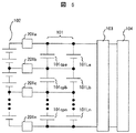
以下本発明の実施例について図面を用いて詳細に説明する。図1は、本発明の第1の実施例を示す図である。図1において、101は第一の蓄電器類(101a〜101n)、102は第二の蓄電器類(102a〜102m)、103は充放電器、104は電源および負荷である。1つの第一の蓄電器類101(101a)と2つの第二の蓄電器類102(102a、102b)が並列に接続され、この対になっている並列接続が、さらに複数段直列に接続されている例を示している。この直列接続された蓄電器類は充放電器103に接続され電源装置を構成する。そして本電源装置は電源および負荷104に接続されている。
【0027】
また、図1において太線で表した第一の蓄電器類101aと第2の蓄電器類102a、102bとの並列接続、これと直列接続される第1の蓄電器類101bと第二の蓄電器類102c、102dとの並列接続、すなわち、直列2段接続は本発明の最小単位接続構成である。この構成によって、第一の蓄電器類の101aと101bの充電バランスをとることができる。さらに直列接続段数を増加し3段、4段、……のように多段直列接続して使用されることになる。第一の蓄電器類101にはリチウム二次電池や電気二重層キャパシタ等を用い、第二の蓄電器類102には電解液の電気分解またはガスの発生と再結合あるいは電解液の補充が可能な鉛電池やニッケル水素電池、ニッケルカドミウム電池、燃料電池などを用いる。
【0028】
充放電器103は双方向のDC/DCコンバータ、または一方向の充電用DC/DCコンバータと放電用のDC/DCコンバータの対で構成することもできる。これらは蓄電器と電源および負荷104に適した電圧、電流制御をおこなう。また、電源および負荷104は商用電源や発電機および一般的な電気機器等である。充放電器103は適時、第二の蓄電器類102を電解液が電気分解する電圧又は発生ガスが再結合をする電圧まで充電する。これにより、第一の蓄電器類101と第二の蓄電器類102は並列接続され、かつこれが少なくとも2段に直列接続されていることによって、第二の蓄電器類102の電解液が電気分解する電圧又は発生ガスが再結合をする電圧により、図1の太線部分の構成における、第一の蓄電器類101の電圧均等化を図ることができる。
【0029】
次に、第二の蓄電器類102の電解液が電気分解する電圧又は発生ガスが再結合をする電圧によって第一の蓄電器の電圧均等化が図られる動作について、図2(A)の等価回路により説明する。図2の(A)に示す(a)は、第一の蓄電器類101と、第二の蓄電器類102の基本構成を示している。すなわち、図1における太線の部分を表わしている。これに対して、図2の(A)において、(b)の部分はその動作を説明するための、等価回路を示している。10a〜10dは例えばツエナーダイオード特性を持った素子である。16a〜16dはコンパレータ、Va〜Vdはツエナー電圧で、コンパレータ16a〜16dは、第二の蓄電器類が過充電により所定の電圧、すなわち等価回路ではツエナー電圧Va〜Vdに達したとき、オンとなりスイッチ12a〜12dを閉とし、抵抗14a〜14dを接続する。そして、第一の蓄電器類101と第二の蓄電器類102の均等化、特に第一の蓄電器の電圧均等化を図ることになる。抵抗14a〜14dは抵抗値が等しい抵抗器である。第二の畜電器類は前記の等価回路のような動作をすることになるので、第一の蓄電器類101(101a、101b)の均等化を図ることができる。
【0030】
このようにして、第一の蓄電器類101と第二の蓄電器類102、すなわち、高出力型の蓄電器と高容量型の蓄電器とを組み合わせることにより、見掛け上高出力で高容量な電源装置の実現が可能になる。例えば、第一の蓄電器類101として高出力のリチウム二次電池を、第二の蓄電器類102として高容量の鉛シール電池を用いる。この場合、鉛シール電池の2直列(102a、102b)とリチウム二次電池の1直列(101a)を並列接続する。さらに、鉛シール電池の2直列(102c、102d)とリチウム二次電池の1直列(101b)の並列接続回路をさらに直列接続する。
【0031】
こうすることによって、鉛シール電池は電解液が電気分解する電圧または発生ガスが再結合をする電圧(過充電電圧)が約2.1Vであり、2直列では約4.2Vになる。一方、リチウム二次電池の使用電圧範囲の上限(耐電圧)は約4.3Vである。このため、鉛シール電池の過充電により鉛シール電池及びリチウム二次電池はそれぞれ2.1V×2と、4.2Vのように均等化される。すなわち、鉛シール電池の直列端電圧が4.2V、リチウム二次電池端電圧が4.2Vに均等化されることになる。
【0032】
鉛シール電池は安価で高容量であるが、大電流充電が不可能であり、無理な大電流充電では寿命が著しく低下する。一方のリチウム二次電池は大電流での充電が可能であるが、高容量化すると比較的高価になる。そこで、両者を組み合わせることにより、高出力と高容量の両立が実現でき、かつ長寿命化、低コスト化を図ることができる。これを模式的に図2の(B)に示す。縦軸は出力で示したが、充電の場合では充電電流が該当する。すなわち、第一の蓄電器は大出力、第二の蓄電池は大容量の蓄電器として使用することができる。
【0033】
また、縦軸を充電電流とすると、第一の蓄電器類は大電流短時間充電が可能であり、第二の蓄電器類は比較的小電流で長時間の充電が必要であることをも示している。すなわち、第一の蓄電器類と第二の蓄電器類とを並列に接続することによって、大出力、大容量蓄電器の特性を兼ね備えた畜電器としての利用をはかることができる特徴がある。大電流充電が可能なので、後述する電気自動車における回生時に、その回生電力を有効に利用し、充電をおこなうことができる特徴がある。
【0034】
図3は本発明の第2の実施例を示す図である。図において、201は電流制限器である。第一の蓄電器類101と第二の蓄電器類102とが電流制限器201を介して並列接続されている。図3では、第一の蓄電器類101に電気二重層キャパシタ101cpa〜101cpnを使用した場合の例を示している。
【0035】
電流制限器201は、例えば、大電流で抵抗が増加する特性をもっているPTC(Positive Thermal Conductor)、ヒュ−ズ等が適用される。あるいは抵抗が採用される。これらは第一の蓄電器類101と第二の蓄電器類102の間を行き来する電流(第一の蓄電器から第二の蓄電器に流れる電流あるいはその逆方向に流れる電流)を制限し、蓄電器の過電流を防止する。また、第一の蓄電器類101や第二の蓄電器類102が短絡故障した場合に並列接続された蓄電器の連鎖的短絡故障を防止できる効果もある。
【0036】
図4は本発明の第3の実施例を示す図である。図4では図1及び図2で示した(a)の第一の蓄電器類101や第二の蓄電器類102がさらに並列接続された例である。そして充放電器103と電源及び負荷104が接続されている。このように複数の直列接続列を更に並列接続することにより、電源装置の容量や出力、寿命等を可変増強できる効果がある。
【0037】
また、第一の実施例と同様に、充放電器103は適時、第二の蓄電器類102を電解液が電気分解する電圧又は発生ガスが再結合をする電圧まで充電する。
【0038】
これにより、各直列接続列の第一の蓄電器類101と第二の蓄電器類102の、複数の並列接続対は第二の蓄電器類102の電解液が電気分解する電圧または発生ガスが再結合をする電圧に均等化されることになる。図4の(a)の部分は図1あるいは図2の(a)の部分に相当し、図4の(b)の部分は図3の構成に該当し、これらを並列接続して図4を構成した例である。
【0039】
図5は本発明の第4の実施例を示す図である。図5おいて、第一の蓄電器類101の中で、電気二重層キャパシタ101cpa〜101cpnと、リチウム二次電池101La〜101Lnとを夫々並列に接続した例である。リチウム二次電池を第三の蓄電器とすると、第三の蓄電器として第一の蓄電器の、リチウム電池を用いた場合である。第一の蓄電器類101と第二の蓄電器類102とが電流制限器201を介して並列接続され、そして、これらの直列接続列が充放電器103に接続され電源装置を構成している場合である。
【0040】
ここで、第一の蓄電器類101(101cpa〜101cpn)、および第三の蓄電器の耐電圧を、第二の蓄電器類102の耐電圧より大きく設定する。すなわち、第一の蓄電器類101(101cpa〜101cpn)、および第三の蓄電器(101La〜101Ln)の使用電圧範囲内で、電圧の均等化を図ることができる。すなわち、第二の蓄電器類102の、電解液の電気分解またはガス発生と再結合が発生するまで充電し、第二の蓄電器類102、それと第一の蓄電器類101のうち、第三の蓄電器(101La〜101Ln)は、この電解液が電気分解する電圧または発生ガスが再結合をする電圧に均等化充電されることになる。
【0041】
いま、第一の蓄電器類101(101cpa〜101cpa)を耐圧が3.5Vの電気二重層キャパシタ、第二の蓄電器類102を電解液の電気分解又はガス発生と再結合の電圧が1.6Vのニッケル水素電池、第三の蓄電器類401を耐圧が4.3Vのリチウム二次電池とすると、ニッケル水素電池の過充電により電気二重層キャパシタ及びリチウム二次電池は3.6Vに均等化される。
【0042】
図6は本発明の第5の実施例を示す図である。図6(A)において501はプラス端子、502はマイナス端子、503はケース、504は中間端子である。複数の第一の蓄電器類101、または第二の蓄電器類102が直列接続され、ケース503に収納されている例である。また、直列接続の両端は電力の授受を担うプラス端子501とマイナス端子502が配設されている。さらに蓄電器類が2個直列に接続される毎に中間端子504が配設されている。
【0043】
この中間端子504とプラス端子501、マイナス端子502を介して他の第一の蓄電器類101または第二の蓄電器類102と並列に接続することが可能となる。図6の(B)はケース503a、503bに収納された蓄電器の並列接続の状況を示している。504a1、504a2はケース503aに収納された蓄電器の中間端子を表わしている。また、504b1、504b2はケース503bに収納された蓄電器の中間端子を表わしている。この端子を相互に接続すれば、図6の(A)に示した直列回路の並列接続が可能となる。
【0044】
図7は本発明の第6の実施例を示す図である。図7おいて601は正極a、602はセパレータa、603は負極a、604は隔壁で、第一の蓄電器類101で構成している。また605は正極b、606はセパレータb、607は負極bで、第二の蓄電器102で構成した場合である。608はプラスリード線、609はマイナスリード線である。
【0045】
正極a601、セパレータa602、負極a603の順に配設され、これらが電解液(図示せず)に含浸され、第一の蓄電器類101の、構成要素の一部を成している。また、正極b605、セパレータb606、負極b607の順に配設され、これらが電解液(図示せず)に含浸され、第二の蓄電器類102の、構成要素の一部を成している。
【0046】
これらは隔壁604で空間的に分離されているが、共通のケース503に収納されている例である。また、正極a601、正極b605、プラス端子501はプラスリード線608で接続されている。同様に負極a603、負極b607、マイナス端子502がマイナスリード線609で接続されている。
【0047】
ここでは、第一の蓄電器類101と第二の蓄電器類102をそれぞれ独立して構成する場合に比べ、プラス端子501やマイナス端子502、プラスリード線608、マイナスリード線609、ケース503が各構成要素を供用し、並列接続対を構成している。その他、図示していないが防爆弁、圧力スイッチ等の保護機構や保護素子等も共用化が可能である。これにより部品点数や、電源としてのコストの低減を図ることができる。
【0048】
図8は本発明の第7の実施例を示す図である。図8では図6の隔壁604が削除され、第一の蓄電器類101と第二の蓄電器類102の構成要素が同一空間に収納されている。このため、電解液も共用化している。本構成は電解液を硫酸水溶液とし、第一の蓄電器類101を電気二重層キャパシタ、第二の蓄電器類102をシール鉛電池とすることで実現できる。また、電解液を水酸化カリウム水溶液とし、第一の蓄電器類101を電気二重層キャパシタ、第二の蓄電器類102をニッケル水素電池とすることでも実現することが可能である。
【0049】
ここでは、第一の蓄電器類101と、第二の蓄電器類102の電極およびセパレータ602、606の実装が積層型で示されているが、捲回型やその他の構成でも実現可能である。
【0050】
また、本発明の第8の実施例として、図7または図8の第一の蓄電器類101と第二の蓄電器類102の、少なくとも一つの電極(一般的には負極)に炭素繊維またはカーボンナノチューブを添加したものを使用することが望ましい。リチウム二次電池や鉛電池は充放電で電極の伸縮を伴う。一方、電気二重層キャパシタやニッケル水素電池は充放電で電極の伸縮を伴わない。これらを共通の空間に収納すると、電気二重層キャパシタやニッケル水素電池にも応力が加わり性能が著しく劣化する。そこで、いずれかの電極(一般的には負極)に炭素繊維またはカーボンナノチューブを添加することにより、炭素繊維またはカーボンナノチューブがこの応力を緩和し、性能の低下を防止することができる。
【0051】
図9は本発明の第9の実施例を示す図である。図9において、蓄電器コントローラ807は、801a〜801cの電池管理回路、802a〜802cの電圧検出回路、803a〜803cの電位変換回路、804の処理回路、805の絶縁回路、806の通信回路、から構成されている。そして、第一の蓄電器類101cpa〜101cpcに、第二の蓄電器類102a、b、102c、d、102e、fがそれぞれ並列に接続され、この並列接続対がさらに複数段(図9の例では3段)直列に接続された例である。また、電池管理回路801が、第一の蓄電器類101と第二の蓄電器類102の並列接続対(例えば、102a、b、と101cpa)にさらに並列に接続されている状態を示している。
【0052】
電池管理回路801(801a〜c)は電位変換回路803(803a〜c)を介して、処理回路804と接続されている。処理回路804は絶縁回路805を介して通信回路806にも接続されている。そして、これらにより電池コントローラ807が構成されている。
【0053】
ここで、電位変換回路803(803a〜c)は、電池管理回路801(801a〜c)で検出された各並列回路の電位レベルを変換して電気信号を伝送する。処理回路804では各並列接続対の端子間電圧をもとに、各並列接続対の充電状態や電圧アンバランスの判定、残量や許容入出力の検出、バイパス回路の駆動等を行う。また、許容放電残量や許容入出力等の情報信号は絶縁回路805で電気的に絶縁された後、通信回路806を介して電源および負荷104、あるいは充放電器103に伝えられる。通信回路のTXは送信手段、RXは受信手段を表わしている。
【0054】
電池管理回路801(801a〜c)は電圧検出回路802(802a〜c)やバイパス回路(図示せず)を有し、並列接続対の端子間電圧を検出する。また、図示していないが、バイパス回路によって各並列接続対の電圧アンバランスを解消する様にバイパス回路を制御することもできる。
【0055】
この電圧アンバランスの解消は、前述の充放電器103による第二の蓄電器類102の電解液が電気分解する電圧または発生ガスが再結合をする電圧によって均等化される。これにより、バイパス回路を使用したとしても、小型化が達成でき、均等化の作用も補強される効果がある。
【0056】
図10は、本発明の電源システムの、一実施形態を示したもので、太陽光の電力変換装置と組み合わせた分散型電源装置の実施の形態を示す図である。図10において、901は商用電源、902は太陽光発電装置、903a、903bは負荷装置、904は制御変換器、905a、905b、905cは切替器である。図10において、前記の、第一の蓄電器類101a〜101dと、第二の蓄電器類102a、b〜102g、h、が並列に接続され、この並列接続対がさらに複数段(この実施例では4段)直列に接続され、これらと蓄電器コントローラ807が接続されている。
【0057】
また、直列接続列のプラス端子501、マイナス端子502は、前述の充放電器103に相当する制御変換器904に接続され、かつ、電池コントローラ807内の通信回路806と制御変換器904内のMCUが接続されている。
【0058】
さらに、前述の電源および負荷104に相当する商用電源901、太陽光発電装置902、負荷装置903が、切替器905a〜905dを介して、制御変換器904に接続されている。また、太陽光発電装置902、負荷装置903、制御変換器904、切替器905a〜905d、電池コントローラ807は、双方向通信で結ばれている。太陽光発電装置902は、太陽電池により、太陽光を直流電力に変換し、インバータ装置(INV)により交流電力を出力する装置である。
【0059】
また、負荷装置903aは、エアコン、冷蔵庫、電子レンジ、照明などの家電品や、モータ、エレベータ、コンピュータ、医療機器などの電気機器や、903bは第2の電源装置の場合もある。そして、制御変換器904は、交流電力を直流電力に変換、または、直流電力を交流電力に変換する充放電器である。また、これら充放電の制御や上述の太陽光発電装置902、負荷装置903などの機器を制御する制御器MCUを有している。MCUは制御信号を切替器905a〜905d等に出力する。
【0060】
ここで、これらの機器は装置内に切替器905を有することもある。また、本発明の電源装置は、図示した構成以外の制御変換器904や、その他の機器の接続形態をとることも可能である。本実施の形態によれば、負荷装置903が必要とする電力を、商用電源901や太陽光発電装置902で賄い切れない時、制御変換器904を介して、蓄電器類から電力を供給する。そして、商用電源901や太陽光発電装置902からの電力供給が過剰となっている時に、制御変換器904を介して、蓄電器類に蓄電する。
【0061】
これらの動作の中で、蓄電器類の端子間電圧が、放電停止や充電停止レベルに達すると、電池コントローラ807はその信号を制御変換器904に送り、制御変換器904は充放電等を制御する。また、蓄電器類の電圧アンバランスを検出すると、バイパス回路を有している場合は、バイパス回路を制御し電圧アンバランスを解消する様に作用する。
【0062】
電圧アンバランスの程度がこのバイパス回路で解消できないレベルと検出した場合は、商用電源901、太陽光発電装置902、負荷装置903、制御変換器904、切替器905を制御し、前述の様に第二の蓄電器類102の電解液が電気分解する電圧又は発生ガスが再結合をする電圧に均等化する作用を併用する。これらの実施の形態では、商用電源901の契約電力や消費電力、太陽光発電装置902の発電定格を下げることが可能となり、設備費やランニングコストの削減を図ることができる。
【0063】
また、消費電力がある時間帯に集中している時に、電源装置から商用電源901に電力を供給し、消費電力が少ない時に、電源装置に蓄電することで、消費電力の集中を緩和し、消費電力の平準化を図ることが可能となる。さらに、制御変換器904のMCUは負荷装置903の電力消費を監視し、負荷装置903を制御するため、省エネや電力の有効利用が達成できる。
【0064】
図11は本発明の電源装置を適用した電気自動車の例を示している。図11において、1001は自動車の駆動用モータジェネレータ、1002は直流負荷装置である。モータジェネレータ1001が制御変換器904を介して複数の蓄電器類の直列接続列に接続されている。モータジェネレータ1001はエンジンの始動や駆動力のアシスト(力行)や発電(回生)をおこなう。そして、力行時には電源装置からモータジェネレータ1001に電力が供給される。回生時には逆にモータジェネレータ1001から電源装置に電力が供給される。
【0065】
また、直流負荷装置1002は電磁弁やオーディオ等の電気負荷や第2の電源装置である。直流負荷装置1002は切替器905を介して蓄電器類の直列接続列に接続されている。
【0066】
これにより発進時にエンジンのトルクをアシストしたり、ブレーキ時には回生エネルギーを電力に変換して蓄えたりすることが可能な自動車が実現できる。特にこの電源装置の場合は、第一の蓄電器類を用いた電源装置であるため、大電流充電が可能であるから、回生時にはその回生エネルギーを充電電力として有効に利用することが出来る効果がある。これまではいわゆる急速充電ができなかったので、その大部分は熱損失となっていた。
【0067】
【発明の効果】
本発明による電源装置によれば、直並列接続された蓄電器類の電圧の均等化を図ることが出来るとともに、分散型電源の一つとして利用できる。また電気自動車に用いることにより回生時電力を電源装置の充電電力として有効に利用できる効果がある。
【図面の簡単な説明】
【図1】 本発明の第1の実施例を示す図である。
【図2】 本発明の基本説明図である。
【図3】 本発明の第2の実施例を示す図である。
【図4】 本発明の第3の実施例を示す図である。
【図5】 本発明の第4の実施例を示す図である。
【図6】 本発明の第5の実施例を示す図である。
【図7】 本発明の第6の実施例を示す図である。
【図8】 本発明の第7の実施例を示す図である。
【図9】 本発明の第9の実施例を示す図である。
【図10】 本発明の電源装置を適用した一実施形態で、太陽光の電力変換装置との組み合わせた電源システムの実施の形態を示す図である。
【図11】 本発明の電源装置を適用した一実施の形態で、電気自動車に用いた場合の例を示す図である。
【図12】 従来のバッテリー充電装置を示す図である。
【符号の説明】
101…第一の蓄電器類、101cpa〜101cpn…第一の蓄電器類の電気二重層キャパシタ、101La〜101Ln…第一の蓄電器類のリチウム二次電池、102…第二の蓄電器類、103…充放電器、104…電源及び負荷、201…電流制限器、501…プラス端子、502…マイナス端子、503…ケース、504…中間端子、601…正極a、602…セパレータa、603…負極a、604…隔壁、605…正極b、606…セパレータb、607…負極b、608…プラスリード線、609…マイナスリード線、801…電池管理回路、802…電圧検出回路、803…電位変換回路、804…処理回路、805…絶縁回路、806…通信回路、807…蓄電器コントローラ、901…商用電源、902…太陽光発電装置、903…負荷装置、904…制御変換器、905…切替器、1001…モータジェネレータ、1002…直流負荷装置、1101…電池、1102電圧検出手段、1103…設定電圧印加手段、1104…比較制御手段、1105…電流可変手段。[0001]
BACKGROUND OF THE INVENTION
The present invention relates to a power supply device in which a large number of capacitors such as lithium secondary battery, nickel metal hydride battery, lead-sealed battery, electric double layer capacitor, and fuel cell are connected in series and parallel, and a distributed power storage device using these, It relates to automobiles.
[0002]
[Prior art]
When the capacitors are connected in series, there is a difference in the voltage of each capacitor due to variations in the capacity, initial voltage, temperature, etc. of each capacitor. It is difficult to share.
[0003]
In particular, when lithium secondary batteries or electric double layer capacitors that use an organic solvent as the electrolyte are connected in series, voltage variations can cause overcharge or overdischarge, leading to explosion or ignition. There is sex. In addition, even if the battery does not rupture or ignite, there arises a problem that the life of the battery is significantly reduced due to overcharge or overdischarge.
[0004]
In addition, when charging and discharging are performed by providing a protection level so as not to cause overcharging or overdischarging, charging stops when the voltage of the high-voltage capacitor reaches the protection level during charging. For this reason, the remaining battery with a low voltage is not fully charged, and charging is stopped halfway leaving a charging capacity.
[0005]
Similarly, at the time of discharging, discharging stops when the voltage of the low-voltage capacitor reaches the protection level. For this reason, the remaining accumulator with a high voltage is left undischarged while leaving a discharge capacity, and the discharge stops halfway.
[0006]
For this reason, compared with the charging / discharging time of an individual capacitor | condenser, when connected in series, charging / discharging time will become short.
[0007]
In order to solve such a problem, there has heretofore been a battery charging device in which the charging current is gradually bypassed by the current varying means as the battery voltage approaches a set value during charging, and the battery state is made uniform. For example, there is JP-A-07-230829 (corresponding USP 5,557,189). FIG. 12 is a diagram showing the battery charging apparatus. In the figure, 1101a to 1101c are batteries, 1102a to 1102c are voltage detection means, 1103 is a set voltage application means, 1104a to 1104c are comparison control means, and 1105a to 1105c are current variable means. The circuit configuration relating to the
[0008]
The current voltage value of the
[0009]
Although the
[0010]
There is also JP-A-2000-78768. This corrects the occurrence of variations during charging of the lithium ion secondary battery, prevents troubles such as overcharging, and improves the service life. Specifically, it is circulated by a negative electrode electrolyte circulation pump and a positive electrode electrolyte circulation pump to correct variations in charge and discharge.
[0011]
Moreover, there is a Japanese translation of PCT publication No. 2000-511398. This is a combination with energy storage elements that are switched in a system for battery equalization. Specifically, a capacitor group is used to shift the charge between batteries connected in series. In this method, electric charge is extracted from a battery having a higher voltage and sent to a battery having a lower voltage.
[0012]
[Problems to be solved by the invention]
The conventional battery charger compares the battery voltage at the time of charging with the set value, and as the battery voltage approaches the set voltage value, the charge current is gradually diverted to the current variable means provided in parallel with the battery, and the battery state Align.
[0013]
However, according to this, since the heat is generated by the current varying means, the current that can be shunted is very small, and the effect of eliminating the voltage variation of the battery is reduced. Conversely, the current variable means having a large heat capacity capable of flowing a large current is large in size and the apparatus becomes large. Furthermore, an electric circuit other than the battery is necessary, which increases the cost. Moreover, a pump must be provided in the method of circulating the electrolyte. In addition, a battery equalizer including a switch circuit for charge transfer by switching and its control circuit is required.
[0014]
The present invention has been made to solve the above-described problems, and an object of the present invention is to provide an inexpensive and small-sized power supply device that can eliminate voltage variations of capacitors connected in series.
[0015]
[Means for Solving the Problems]
The power supply device according to the present invention connects in parallel a first capacitor and a second capacitor capable of electrolyzing an electrolytic solution or recombining a generated gas. And this parallel connection pair is further connected in series, and is connected with a charger / discharger. When appropriate, the charger / discharger charges to a voltage at which the electrolyte of the second battery is electrolyzed or a voltage at which the generated gas recombines. As a result, a plurality of parallel connection pairs of the first capacitor and the second capacitor are equalized to a voltage at which the electrolyte of the second capacitor is electrolyzed or a voltage at which the generated gas is recombined. The
[0016]
In the parallel connection pair of the first capacitor and the second capacitor of the present invention, the first capacitor and the second capacitor are connected in parallel via a current limiter. The current limiter limits the current flowing between the first capacitor and the second capacitor, prevents overcurrent of the first capacitor or the second capacitor, and protects against failure. it can.
[0017]
Moreover, the serial connection row | line | column of the parallel connection pair of said 1st electrical storage device and said 2nd electrical storage device of this invention is further connected in parallel. Thereby, the capacity | capacitance of a power supply device, an output, a lifetime, etc. can be variably increased.
[0018]
In the present invention, the withstand voltage of the first capacitors is set larger than the withstand voltage of the second capacitors. That is, electrolysis or gas generation and recombination of the electrolyte solution of the second capacitor within the working voltage range of the first capacitor, the second capacitor and the first capacitor are The voltage at which the electrolyte is electrolyzed or the voltage at which the generated gas is recombined is equalized.
[0019]
In another power supply device of the present invention, at least one of the first capacitor and the second capacitor is configured by connecting a plurality of capacitors in series. In addition to the main plus terminal and minus terminal, an intermediate terminal is provided for each number of units connected in series. The first capacitor and the second capacitor can be connected in parallel via the intermediate terminal and the main terminal.
[0020]
In another power supply device of the present invention, the first capacitor and the second capacitor are configured by using at least one component. As a result, the number of parts and cost can be reduced. The component used here is preferably an electrolyte.
[0021]
Also, carbon fiber or carbon nanotube is added to at least one electrode of the first capacitor and the second capacitor. In particular, in a battery system that involves expansion and contraction of electrodes during charge and discharge, this stress is relieved by carbon fibers or carbon nanotubes.
[0022]
In another power supply device of the present invention, a battery management circuit is added in parallel with the parallel connection pair of the first capacitor and the second capacitor. This makes it possible to enhance voltage equalization and detect the state of the parallel connection pair.
[0023]
In addition, a power supply device composed of a first power storage device and a second power storage device is a power storage device connected in parallel with another power supply device, and when the other power supply device is short of power, from the power storage device Assists in power supply, and when surplus power is generated in the other power supply device, the power is charged until the voltage at which the electrolyte of the second battery of the power storage device is electrolyzed or the generated gas is recombined with that power It is characterized by a distributed power supply system with a charger.
[0024]
In addition, in an electric vehicle having a motor generator for driving and regenerative power generation of an electric vehicle, and mounting the capacitor power supply device connected to the motor generator, the capacitor power supply device is connected to the first capacitor and the first capacitor A second battery connected in parallel to the second battery, and a charger capable of charging the second battery to a voltage at which the electrolyte can be electrolyzed or the generated gas can be recombined. There is a feature in the electric vehicle equipped with the power supply device.
[0025]
In addition, this invention is applied to the series parallel connection body of various electrical storage devices and fuel cells which have an electric power storage function, such as a lithium secondary battery, a nickel hydride battery, a lead seal battery, and an electric double layer capacitor.
[0026]
DETAILED DESCRIPTION OF THE INVENTION
Hereinafter, embodiments of the present invention will be described in detail with reference to the drawings. FIG. 1 is a diagram showing a first embodiment of the present invention. In FIG. 1, 101 is a first capacitor (101a to 101n), 102 is a second capacitor (102a to 102m), 103 is a charger / discharger, and 104 is a power source and a load. One first capacitor 101 (101a) and two second capacitors 102 (102a, 102b) are connected in parallel, and the parallel connection in pairs is further connected in series in multiple stages. An example is shown. The capacitors connected in series are connected to the charger /
[0027]
In addition, the
[0028]
The charger /
[0029]
Next, with respect to the operation of equalizing the voltage of the first capacitor by the voltage at which the electrolyte of the
[0030]
In this way, the first
[0031]
By doing so, the voltage at which the electrolytic solution is electrolyzed or the voltage at which the generated gas is recombined (overcharge voltage) is about 2.1 V in the lead-sealed battery, and about 4.2 V in two series. On the other hand, the upper limit (withstand voltage) of the working voltage range of the lithium secondary battery is about 4.3V. For this reason, the lead-seal battery and the lithium secondary battery are equalized to 2.1 V × 2 and 4.2 V, respectively, by overcharging the lead-seal battery. That is, the series terminal voltage of the lead-sealed battery is equalized to 4.2V, and the lithium secondary battery terminal voltage is equalized to 4.2V.
[0032]
Lead-sealed batteries are inexpensive and have a high capacity, but cannot be charged with a large current. One lithium secondary battery can be charged with a large current, but becomes relatively expensive when the capacity is increased. Therefore, by combining the two, it is possible to realize both high output and high capacity, and it is possible to extend the life and cost. This is schematically shown in FIG. The vertical axis indicates the output, but in the case of charging, the charging current corresponds. That is, the first battery can be used as a high-power battery and the second battery can be used as a battery having a large capacity.
[0033]
In addition, when the vertical axis is the charging current, the first capacitors can be charged with a large current for a short time, and the second capacitors can be charged with a relatively small current for a long time. Yes. That is, by connecting the first capacitor and the second capacitor in parallel, there is a feature that it can be used as a livestock battery having the characteristics of a large output and large capacity capacitor. Since the large current charging is possible, there is a feature that the regenerative power can be effectively used and charged at the time of regeneration in an electric vehicle described later.
[0034]
FIG. 3 is a diagram showing a second embodiment of the present invention. In the figure, 201 is a current limiter. The
[0035]
The current limiter 201 is, for example, a PTC (Positive Thermal Conductor having a characteristic that resistance increases with a large current. ), Fuse etc. are applied. Alternatively, a resistor is employed. These limit the current (current flowing from the first capacitor to the second capacitor or the current flowing in the opposite direction) between the
[0036]
FIG. 4 is a diagram showing a third embodiment of the present invention. FIG. 4 shows an example in which the
[0037]
Similarly to the first embodiment, the charger /
[0038]
As a result, the plurality of parallel connection pairs of the
[0039]
FIG. 5 is a diagram showing a fourth embodiment of the present invention. FIG. 5 shows an example in which the electric
[0040]
Here, the withstand voltage of the first capacitor 101 (101 cpa to 101 cpn) and the third capacitor is set larger than the withstand voltage of the
[0041]
Now, the first capacitor 101 (101 cpa to 101 cpa) is an electric double layer capacitor having a withstand voltage of 3.5 V, and the
[0042]
FIG. 6 is a diagram showing a fifth embodiment of the present invention. In FIG. 6A, 501 is a plus terminal, 502 is a minus terminal, 503 is a case, and 504 is an intermediate terminal. In this example, a plurality of
[0043]
Via the
[0044]
FIG. 7 is a diagram showing a sixth embodiment of the present invention. In FIG. 7, 601 is a positive electrode a, 602 is a separator a, 603 is a negative electrode a, and 604 is a partition wall, which is constituted by the
[0045]
A positive electrode a601, a separator a602, and a negative electrode a603 are arranged in this order, and these are impregnated with an electrolytic solution (not shown) to form part of the constituent elements of the
[0046]
Although these are spatially separated by a partition wall 604, they are examples stored in a
[0047]
Here, compared to the case where the
[0048]
FIG. 8 is a diagram showing a seventh embodiment of the present invention. In FIG. 8, the partition wall 604 of FIG. 6 is deleted, and the components of the
[0049]
Here, the
[0050]
Further, as an eighth embodiment of the present invention, at least one electrode (generally a negative electrode) of the
[0051]
FIG. 9 is a diagram showing a ninth embodiment of the present invention. In FIG. 9, the
[0052]
The battery management circuit 801 (801a to c) is connected to the
[0053]
Here, the potential conversion circuit 803 (803a-c) converts the potential level of each parallel circuit detected by the battery management circuit 801 (801a-c) and transmits an electrical signal. The
[0054]
The battery management circuit 801 (801a to 801c) has a voltage detection circuit 802 (802a to 802c) and a bypass circuit (not shown), and detects a voltage between terminals of the parallel connection pair. Although not shown, the bypass circuit can be controlled by the bypass circuit so as to eliminate the voltage imbalance of each parallel connection pair.
[0055]
The elimination of this voltage imbalance is equalized by the voltage at which the electrolyte of the
[0056]
FIG. 10 shows an embodiment of the power supply system of the present invention, and is a diagram showing an embodiment of a distributed power supply device combined with a solar power conversion device. In FIG. 10, 901 is a commercial power source, 902 is a solar power generation device, 903a and 903b are load devices, 904 is a control converter, and 905a, 905b and 905c are switching devices. In FIG. 10, the
[0057]
Further, the
[0058]
Furthermore, the
[0059]
Further, the load device 903a may be a home appliance such as an air conditioner, a refrigerator, a microwave oven, or a lighting, an electric device such as a motor, an elevator, a computer, or a medical device, and 903b may be a second power supply device. The
[0060]
Here, these devices may have a
[0061]
In these operations, when the voltage between the terminals of the capacitors reaches the discharge stop or charge stop level, the
[0062]
When it is detected that the level of voltage imbalance cannot be eliminated by this bypass circuit, the
[0063]
In addition, when power consumption is concentrated in a certain time zone, power is supplied from the power supply device to the
[0064]
FIG. 11 shows an example of an electric vehicle to which the power supply device of the present invention is applied. In FIG. 11, reference numeral 1001 denotes an automobile drive motor generator, and 1002 denotes a DC load device. A motor generator 1001 is connected to a series connection row of a plurality of capacitors via a
[0065]
The DC load device 1002 is an electric load such as an electromagnetic valve or audio, or a second power supply device. The DC load device 1002 is connected to a series connection row of capacitors through a
[0066]
As a result, it is possible to realize an automobile capable of assisting the engine torque at the time of starting, and converting and storing regenerative energy into electric power during braking. In particular, in the case of this power supply device, since it is a power supply device using the first capacitors, it is possible to charge a large current, and therefore, there is an effect that the regenerative energy can be effectively used as charging power at the time of regeneration. . Until now, so-called rapid charging has not been possible, and most of the heat has been lost.
[0067]
【The invention's effect】
The power supply apparatus according to the present invention can equalize the voltages of capacitors connected in series and parallel, and can be used as one of distributed power sources. In addition, when used in an electric vehicle, there is an effect that the electric power at the time of regeneration can be effectively used as charging power for the power supply device.
[Brief description of the drawings]
FIG. 1 is a diagram showing a first embodiment of the present invention.
FIG. 2 is a basic explanatory view of the present invention.
FIG. 3 is a diagram showing a second embodiment of the present invention.
FIG. 4 is a diagram showing a third embodiment of the present invention.
FIG. 5 is a diagram showing a fourth embodiment of the present invention.
FIG. 6 is a diagram showing a fifth embodiment of the present invention.
FIG. 7 is a diagram showing a sixth embodiment of the present invention.
FIG. 8 is a diagram showing a seventh embodiment of the present invention.
FIG. 9 is a diagram showing a ninth embodiment of the present invention.
FIG. 10 is a diagram showing an embodiment of a power supply system in combination with a solar power converter in an embodiment to which the power supply device of the present invention is applied.
FIG. 11 is a diagram showing an example of an electric vehicle according to an embodiment to which the power supply device of the present invention is applied.
FIG. 12 is a diagram illustrating a conventional battery charging device.
[Explanation of symbols]
DESCRIPTION OF
Claims (12)
該蓄電器の充放電を制御する充放電器とを備え、
前記蓄電器は、
直列接続された少なくとも2つの第一の蓄電器類と、
該第一の蓄電器類の充電バランスをとるためのものであって、前記第一の蓄電器類を直列接続したものに並列接続された充電バランス手段とを有しており、
前記充電バランス手段は、
電解液が電気分解する電圧または発生ガスが再結合が可能な第二の蓄電器類を用いて構成したものであって、
前記第一の蓄電器類のそれぞれに対応させて前記第二の蓄電器類を設け、前記第二の蓄電器類を対応する前記第一の蓄電器類に並列接続し、かつ前記第二の蓄電器類を直列接続して構成したものであり、
前記蓄電器類は、前記第二の蓄電器類の電解液が電気分解する電圧または発生ガスが再結合が可能な電圧まで前記第二の蓄電器類のそれぞれを充電させることが可能なものであり、
前記第一の蓄電器類のそれぞれは、前記第二の蓄電器類のそれぞれが、電解液が電気分解する電圧または発生ガスの再結合が可能な電圧まで前記充放電器によって充電されることにより均等充電されることを特徴とする電源装置。A capacitor,
A charger / discharger for controlling charging / discharging of the capacitor,
The capacitor is
At least two first capacitors connected in series;
Charge balance means for balancing the first capacitors, the charge balance means connected in parallel to those connected in series with the first capacitors,
The charging balance means includes
It is configured by using a second battery capable of recombining a voltage at which an electrolytic solution is electrolyzed or a generated gas,
The second capacitors are provided corresponding to the first capacitors, the second capacitors are connected in parallel to the corresponding first capacitors, and the second capacitors are connected in series. Connected and configured,
The capacitors are capable of charging each of the second capacitors to a voltage at which the electrolyte of the second capacitors is electrolyzed or a voltage at which the generated gas can be recombined,
Each of the first capacitors is charged equally by being charged by the charger / discharger to a voltage at which the electrolyte is electrolyzed or a voltage at which the generated gas can be recombined. A power supply device.
前記第一の蓄電器類と前記第二の蓄電器類は電流制限器あるいは抵抗を介して並列接続されていることを特徴とする電源装置。The power supply device according to claim 1,
The first power storage device and the second power storage device are connected in parallel via a current limiter or a resistor.
前記蓄電器が並列接続されていることを特徴とする電源装置。The power supply device according to claim 1,
A power supply device, wherein the capacitors are connected in parallel.
前記第一の蓄電器類の耐電圧は前記第二の蓄電器類の耐電圧よりも大きいことを特徴とする電源装置。The power supply device according to claim 1,
The power supply device according to claim 1, wherein a withstand voltage of the first capacitors is larger than a withstand voltage of the second capacitors.
前記第一の蓄電器類のそれぞれには、前記第二の蓄電器類を複数直列接続したものが並列接続されていることを特徴とする電源装置。The power supply device according to claim 1,
A power supply device , wherein a plurality of the second capacitors connected in series are connected in parallel to each of the first capacitors .
前記蓄電器は、前記第一の蓄電器類を複数直列接続した第一の蓄電器と、前記第二の蓄電器類を複数直列接続した第二の蓄電器とが並列接続されたものであり、
前記第一の蓄電器類と前記第二の蓄電器類との対応するもの同士が、前記第一の蓄電器及び第二の蓄電器の双方に前記対応関係に基づいて設けられた中間端子を介して並列接続されていることを特徴とする電源装置。The power supply device according to claim 1,
The capacitor is a parallel connection of a first capacitor having a plurality of first capacitors connected in series and a second capacitor having a plurality of second capacitors connected in series,
The corresponding ones of the first capacitor and the second capacitor are connected in parallel via an intermediate terminal provided to both the first capacitor and the second capacitor based on the corresponding relationship. The power supply device characterized by the above-mentioned.
前記蓄電器は、前記第一の蓄電器類を複数直列接続した第一の蓄電器と、前記第二の蓄電器類を複数直列接続した第二の蓄電器とが並列接続されたものであり、
前記第一の蓄電器類と前記第二の蓄電器類との対応するもの同士が、前記第一の蓄電器及び第二の蓄電器の双方に前記対応関係に基づいて設けられた中間端子を介して並列接続されていることを特徴とする電源装置。The power supply device according to claim 5,
The capacitor is a parallel connection of a first capacitor having a plurality of first capacitors connected in series and a second capacitor having a plurality of second capacitors connected in series,
The corresponding ones of the first capacitor and the second capacitor are connected in parallel via an intermediate terminal provided to both the first capacitor and the second capacitor based on the corresponding relationship. The power supply device characterized by the above-mentioned.
前記第一の蓄電器類と前記第二の蓄電器類は、その構成要素が少なくとも一つ以上共用化されていることを特徴とする電源装置。The power supply device according to claim 1,
The first power storage device and the second power storage device are characterized in that at least one of the components is shared.
前記共用化されている構成要素は電解液であることを特徴とする電源装置。The power supply device according to claim 8, wherein
The power supply apparatus according to claim 1, wherein the shared component is an electrolytic solution.
前記第一の蓄電器類と前記第二の蓄電器類の少なくとも一つは、電極に炭素繊維またはカーボンナノチューブを有することを特徴とする電源装置。The power supply device according to claim 8, wherein
At least one of the first capacitor and the second capacitor has a carbon fiber or a carbon nanotube as an electrode.
前記電源装置に並列接続された他の電源装置とを有し、
前記蓄電器は、
直列接続された少なくとも2つの第一の蓄電器類と、
該第一の蓄電器類の充電バランスをとるためのものであって、前記第一の蓄電器類を直列接続したものに並列接続された充電バランス手段とを有しており、
前記充電バランス手段は、
電解液が電気分解する電圧または発生ガスが再結合が可能な第二の蓄電器類を用いて構成したものであって、
前記第一の蓄電器類のそれぞれに対応させて前記第二の蓄電器類を設け、前記第二の蓄電器類を対応する前記第一の蓄電器類に並列接続し、かつ前記第二の蓄電器類を直列接続して構成したものであり、
前記蓄電器類は、前記第二の蓄電器類の電解液が電気分解する電圧または発生ガスが再結合が可能な電圧まで前記第二の蓄電器類のそれぞれを充電させることが可能なものであり、
前記第一の蓄電器類のそれぞれは、前記第二の蓄電器類のそれぞれが、電解液が電気分解する電圧または発生ガスの再結合が可能な電圧まで前記充放電器によって充電されることにより均等充電され、
前記他の電源装置が電力不足の場合、前記電源装置から電力供給を援助し、
前記他の電源装置で余剰電力が発生した場合、前記電源装置の前記第一蓄電器類のそれぞれを前記余剰電力により、前記第二の蓄電器類の電解液が電気分解する電圧または発生ガスが再結合する電圧まで充電することを特徴とする分散型電源システム。A power supply device including a capacitor and a charger / discharger that controls charging / discharging of the capacitor;
Another power supply device connected in parallel to the power supply device,
The capacitor is
At least two first capacitors connected in series;
Charge balance means for balancing the first capacitors, the charge balance means connected in parallel to those connected in series with the first capacitors,
The charging balance means includes
It is configured by using a second battery capable of recombining a voltage at which an electrolytic solution is electrolyzed or a generated gas,
The second capacitors are provided corresponding to the first capacitors, the second capacitors are connected in parallel to the corresponding first capacitors, and the second capacitors are connected in series. Connected and configured,
The capacitors are capable of charging each of the second capacitors to a voltage at which the electrolyte of the second capacitors is electrolyzed or a voltage at which the generated gas can be recombined,
Each of the first capacitors is charged equally by being charged by the charger / discharger to a voltage at which the electrolyte is electrolyzed or a voltage at which the generated gas can be recombined. And
If the other power supply is short of power, assist power supply from the power supply,
When surplus power is generated in the other power supply device, the voltage or generated gas at which the electrolyte of the second capacitor is electrolyzed by the surplus power in each of the first capacitors of the power supply device is recombined A distributed power supply system characterized by charging up to a voltage to be applied.
車両の力行時に前記電源装置から供給された電力によって駆動されると共に、車両の回生時に発電する電動発電機とを有し、
前記蓄電器は、
直列接続された少なくとも2つの第一の蓄電器類と、
該第一の蓄電器類の充電バランスをとるためのものであって、前記第一の蓄電器類を直列接続したものに並列接続された充電バランス手段とを有しており、
前記充電バランス手段は、
電解液が電気分解する電圧または発生ガスが再結合が可能な第二の蓄電器類を用いて構成したものであって、
前記第一の蓄電器類のそれぞれに対応させて前記第二の蓄電器類を設け、前記第二の蓄電器類を対応する前記第一の蓄電器類に並列接続し、かつ前記第二の蓄電器類を直列接続して構成したものであり、
前記蓄電器類は、前記第二の蓄電器類の電解液が電気分解する電圧または発生ガスが再結合が可能な電圧まで前記第二の蓄電器類のそれぞれを充電させることが可能なものであり、
前記第一の蓄電器類のそれぞれは、前記第二の蓄電器類のそれぞれが、電解液が電気分解する電圧または発生ガスの再結合が可能な電圧まで前記充放電器によって充電されることにより均等充電され、
車両の回生時、前記電動発電機の発電電力により前記電源装置の前記第一の蓄電器類のそれぞれを、前記第二の蓄電器類の電解液が電気分解する電圧または発生ガスが再結合する電圧まで充電することを特徴とする電気自動車。A power supply device including a capacitor and a charger / discharger that controls charging / discharging of the capacitor;
A motor generator that is driven by the power supplied from the power supply device during powering of the vehicle and that generates power during regeneration of the vehicle;
The capacitor is
At least two first capacitors connected in series;
Charge balance means for balancing the first capacitors, the charge balance means connected in parallel to those connected in series with the first capacitors,
The charging balance means includes
It is configured by using a second battery capable of recombining a voltage at which an electrolytic solution is electrolyzed or a generated gas,
The second capacitors are provided corresponding to the first capacitors, the second capacitors are connected in parallel to the corresponding first capacitors, and the second capacitors are connected in series. Connected and configured,
The capacitors are capable of charging each of the second capacitors to a voltage at which the electrolyte of the second capacitors is electrolyzed or a voltage at which the generated gas can be recombined,
Each of the first capacitors is charged equally by being charged by the charger / discharger to a voltage at which the electrolyte is electrolyzed or a voltage at which the generated gas can be recombined. And
During regeneration of the vehicle, each of the first capacitors of the power supply device is generated by the power generated by the motor generator until the voltage at which the electrolyte of the second capacitors is electrolyzed or the voltage at which the generated gas is recombined. An electric vehicle characterized by charging.
Priority Applications (8)
| Application Number | Priority Date | Filing Date | Title |
|---|---|---|---|
| JP2001357879A JP3809549B2 (en) | 2001-11-22 | 2001-11-22 | Power supply device, distributed power supply system, and electric vehicle equipped with the same |
| US10/083,645 US6680600B2 (en) | 2001-11-22 | 2002-02-27 | Power supply unit, distributed power supply system and electric vehicle loaded therewith |
| KR1020020021221A KR100879762B1 (en) | 2001-11-22 | 2002-04-18 | Power supply unit, distributed power supply system and electric vehicle loading it |
| EP02008275A EP1315227A3 (en) | 2001-11-22 | 2002-04-19 | Power supply unit, distributed power supply system and electric vehicle loaded therewith |
| US10/266,698 US6747438B2 (en) | 2001-11-22 | 2002-10-09 | Power supply unit, distributed power supply system and electric vehicle loaded therewith |
| US10/266,691 US6700349B2 (en) | 2001-11-22 | 2002-10-09 | Power supply unit, distributed power supply system and electric vehicle loaded therewith |
| US10/780,685 US6917181B2 (en) | 2001-11-22 | 2004-02-19 | Power supply unit, distributed power supply system and electric vehicle loaded therewith |
| US10/984,862 US6977480B2 (en) | 2001-11-22 | 2004-11-10 | Power supply unit, distributed power supply system and electric vehicle loaded therewith |
Applications Claiming Priority (1)
| Application Number | Priority Date | Filing Date | Title |
|---|---|---|---|
| JP2001357879A JP3809549B2 (en) | 2001-11-22 | 2001-11-22 | Power supply device, distributed power supply system, and electric vehicle equipped with the same |
Publications (3)
| Publication Number | Publication Date |
|---|---|
| JP2003164068A JP2003164068A (en) | 2003-06-06 |
| JP2003164068A5 JP2003164068A5 (en) | 2004-08-19 |
| JP3809549B2 true JP3809549B2 (en) | 2006-08-16 |
Family
ID=19169153
Family Applications (1)
| Application Number | Title | Priority Date | Filing Date |
|---|---|---|---|
| JP2001357879A Expired - Fee Related JP3809549B2 (en) | 2001-11-22 | 2001-11-22 | Power supply device, distributed power supply system, and electric vehicle equipped with the same |
Country Status (4)
| Country | Link |
|---|---|
| US (5) | US6680600B2 (en) |
| EP (1) | EP1315227A3 (en) |
| JP (1) | JP3809549B2 (en) |
| KR (1) | KR100879762B1 (en) |
Families Citing this family (108)
| Publication number | Priority date | Publication date | Assignee | Title |
|---|---|---|---|---|
| US20040201365A1 (en) * | 2001-04-05 | 2004-10-14 | Electrovaya Inc. | Energy storage device for loads having variable power rates |
| CA2343489C (en) * | 2001-04-05 | 2007-05-22 | Electrofuel, Inc. | Energy storage device for loads having variable power rates |
| EP1377477B1 (en) * | 2001-04-05 | 2006-12-27 | Electrovaya Inc. | Energy storage device for loads having variable power rates |
| JP4605952B2 (en) | 2001-08-29 | 2011-01-05 | 株式会社日立製作所 | Power storage device and control method thereof |
| JPWO2003034523A1 (en) * | 2001-10-11 | 2005-02-03 | 株式会社日立製作所 | Home fuel cell system |
| JP3809549B2 (en) * | 2001-11-22 | 2006-08-16 | 株式会社日立製作所 | Power supply device, distributed power supply system, and electric vehicle equipped with the same |
| US7126294B2 (en) * | 2002-01-31 | 2006-10-24 | Ebara Corporation | Method and device for controlling photovoltaic inverter, and feed water device |
| KR20030094002A (en) * | 2002-05-30 | 2003-12-11 | 엔이씨 도낀 가부시끼가이샤 | Hybrid power supply system |
| AU2002951291A0 (en) * | 2002-09-09 | 2002-09-19 | Energy Storage Systems Pty Ltd | A power supply |
| US20050057221A1 (en) * | 2002-12-19 | 2005-03-17 | Hans Desilvestro | Electrical connecting device for rechargeable electrochemical energy storage system |
| WO2005008266A1 (en) * | 2003-07-09 | 2005-01-27 | Premium Power Corporation | Device for monitoring and charging of a selected group of battery cells |
| US7006898B2 (en) * | 2003-07-17 | 2006-02-28 | Proton Energy Systems, Inc. | Method and apparatus for operating and controlling a power system |
| RU2335831C2 (en) * | 2003-09-18 | 2008-10-10 | Коммонвелт Сайентифик Энд Индастриал Рисерч Органайзейшн | High-efficiency storage batteries |
| JP4169128B2 (en) * | 2003-11-11 | 2008-10-22 | 株式会社リコー | Capacitor charging semiconductor device |
| JP2005160233A (en) * | 2003-11-26 | 2005-06-16 | Makita Corp | Battery pack and cell battery pack |
| US20050118465A1 (en) * | 2003-12-02 | 2005-06-02 | Doob Llc | Multiple voltages DC battery power supply system |
| WO2005070228A1 (en) * | 2004-01-26 | 2005-08-04 | Fuji Oil Company, Limited | Oil-in-water type emulsion |
| FR2866279B1 (en) * | 2004-02-18 | 2006-04-28 | Vehicules Electr Soc D | POWER WHEEL DRIVE SYSTEM OF AN ELECTRIC MOTOR VEHICLE COMPRISING TWO MOTORS AND TWO BATTERIES |
| US7668505B2 (en) * | 2004-09-10 | 2010-02-23 | Honeywell International Inc. | Radio having a MEMS preselect filter |
| JP4186916B2 (en) * | 2004-11-18 | 2008-11-26 | 株式会社デンソー | Battery pack management device |
| DE102004057330B3 (en) * | 2004-11-27 | 2006-03-30 | Leoni Wiring Systems Uk Ltd. | Method and equipment for monitoring leakage from electrical supply network on board road vehicle to carbon-fiber bodywork involves several measuring points connected to monitoring circuit |
| US20060261783A1 (en) * | 2005-05-23 | 2006-11-23 | Paul Gamboa | Electronic battery module (EBM) with bidirectional DC-DC converter |
| US8120308B2 (en) * | 2005-08-24 | 2012-02-21 | Ward Thomas A | Solar panel charging system for electric vehicle that charges individual batteries with direct parallel connections to solar panels |
| JP2009506742A (en) * | 2005-08-24 | 2009-02-12 | トーマス エイ ウォード | Hybrid vehicle having a low voltage solar panel that charges a high voltage battery using a series charger that separately charges each cell of the high voltage battery connected in series |
| DE102006005334B4 (en) * | 2006-02-07 | 2022-12-22 | Bayerische Motoren Werke Aktiengesellschaft | Method for monitoring and/or controlling or regulating the voltage of at least one cell group in a cell assembly of an energy store, as well as cell group logic and central logic for carrying out the method |
| US7667432B2 (en) | 2006-04-27 | 2010-02-23 | Tesla Motors, Inc. | Method for interconnection of battery packs and battery assembly containing interconnected battery packs |
| DK1855344T3 (en) | 2006-05-11 | 2011-09-26 | Hoppecke Batterien Gmbh & Co Kg | accumulator |
| TWI318472B (en) * | 2006-05-19 | 2009-12-11 | Iner Aec Executive Yuan | Fuel cell apparatus and a charging/discharging management system and method using for such apparatus |
| JP4413888B2 (en) | 2006-06-13 | 2010-02-10 | 株式会社東芝 | Storage battery system, in-vehicle power supply system, vehicle, and method for charging storage battery system |
| KR100837003B1 (en) * | 2006-09-12 | 2008-06-10 | 엘에스전선 주식회사 | Circuit for equaling of voltage and Electric energy storage device having the same |
| JP5277595B2 (en) * | 2006-09-26 | 2013-08-28 | セイコーエプソン株式会社 | Apparatus, device, transmission / reception system, and control method including circuit |
| AR064292A1 (en) * | 2006-12-12 | 2009-03-25 | Commw Scient Ind Res Org | ENHANCED ENERGY STORAGE DEVICE |
| AR067238A1 (en) * | 2007-03-20 | 2009-10-07 | Commw Scient Ind Res Org | OPTIMIZED DEVICES FOR ENERGY STORAGE |
| US7772716B2 (en) * | 2007-03-27 | 2010-08-10 | Newdoll Enterprises Llc | Distributed maximum power point tracking system, structure and process |
| US8381849B2 (en) * | 2007-03-30 | 2013-02-26 | The Regents Of The University Of Michigan | Vehicle hybrid energy system |
| DE102007021065A1 (en) * | 2007-05-04 | 2008-11-06 | BSH Bosch und Siemens Hausgeräte GmbH | electrical appliance |
| EP2169760A4 (en) * | 2007-05-18 | 2011-04-27 | Panasonic Corp | Battery pack and battery system |
| DE102007041526A1 (en) * | 2007-08-10 | 2009-02-12 | Robert Bosch Gmbh | Energy storage, in particular accumulator |
| JP5262027B2 (en) * | 2007-09-07 | 2013-08-14 | パナソニック株式会社 | Battery pack and battery system |
| JP2009080939A (en) * | 2007-09-25 | 2009-04-16 | Panasonic Corp | Power source system and control method of battery assembly |
| US8358107B2 (en) | 2007-12-31 | 2013-01-22 | Intel Corporation | Bidirectional power management techniques |
| JP5319138B2 (en) * | 2008-03-07 | 2013-10-16 | 株式会社東芝 | Battery system |
| CZ2008169A3 (en) * | 2008-03-14 | 2009-09-23 | Ydun, S. R. O. | Lead-free starting accumulator battery intended particularly for internal combustion engines and motor vehicles |
| US8076797B2 (en) * | 2008-05-15 | 2011-12-13 | Indy Power Systems Llc | Energy transfer circuit and method |
| DE102008002179A1 (en) * | 2008-06-03 | 2009-12-10 | Robert Bosch Gmbh | Electric energy storage |
| EP2294687B1 (en) * | 2008-06-27 | 2016-08-24 | ABB Research Ltd. | Battery energy source arrangement and voltage source converter system |
| US20110266993A1 (en) * | 2008-11-10 | 2011-11-03 | Himangshu Rai Vaish | Systems and methods for solar based battery charging |
| US8115446B2 (en) * | 2008-11-12 | 2012-02-14 | Ford Global Technologies, Llc | Automotive vehicle power system |
| FR2943473B1 (en) * | 2009-03-17 | 2012-11-16 | Peugeot Citroen Automobiles Sa | BATTERY RECHARGING SYSTEM |
| CA2759689A1 (en) | 2009-04-23 | 2010-10-28 | The Furukawa Battery Co., Ltd. | Method for producing negative plate for use in lead-acid battery and lead-acid battery |
| MX2012002415A (en) | 2009-08-27 | 2012-06-25 | Commw Scient Ind Res Org | Electrical storage device and electrode thereof. |
| JP5797384B2 (en) | 2009-08-27 | 2015-10-21 | 古河電池株式会社 | Composite capacitor negative electrode plate for lead acid battery and lead acid battery |
| JP5711483B2 (en) | 2009-08-27 | 2015-04-30 | 古河電池株式会社 | Method for producing negative electrode plate of composite capacitor for lead storage battery and lead storage battery |
| DE102009041005A1 (en) * | 2009-09-10 | 2011-03-24 | Bayerische Motoren Werke Aktiengesellschaft | Device for balancing an energy store |
| US11218003B2 (en) * | 2009-09-22 | 2022-01-04 | Phoenix Broadband Technologies, Llc | Method and apparatus for intelligent battery charge equalization and monitoring |
| CN102782980A (en) * | 2010-02-19 | 2012-11-14 | 本田技研工业株式会社 | Power supply system and electric vehicle |
| KR20110134751A (en) | 2010-06-09 | 2011-12-15 | 삼성에스디아이 주식회사 | A battery pack and method for controlling the battery pack |
| TWI423556B (en) * | 2010-06-28 | 2014-01-11 | Compal Communications Inc | Battery control system |
| US9040187B2 (en) * | 2010-07-13 | 2015-05-26 | Apple, Inc. | Battery pack with cells of different capacities electrically coupled in parallel |
| CN102340041B (en) * | 2010-07-16 | 2014-04-16 | 汉达精密电子(昆山)有限公司 | Battery pack |
| JP5618359B2 (en) * | 2010-08-02 | 2014-11-05 | Necエナジーデバイス株式会社 | Secondary battery pack connection control method and power storage system |
| JP2012039821A (en) | 2010-08-10 | 2012-02-23 | Toshiba Corp | Power fluctuation relaxing device of power generating system and power fluctuation relaxing method |
| US8981710B2 (en) | 2010-09-20 | 2015-03-17 | Indy Power Systems Llc | Energy management system |
| JP2012133959A (en) | 2010-12-21 | 2012-07-12 | Furukawa Battery Co Ltd:The | Composite capacitor negative electrode plate for lead storage battery, and lead storage battery |
| EP2686195B1 (en) * | 2011-03-16 | 2019-10-30 | CPS Technology Holdings LLC | Systems and methods for controlling multiple storage devices |
| US9190868B2 (en) * | 2011-05-06 | 2015-11-17 | Ford Global Technologies, Llc | Vehicle and method for charging vehicle batteries |
| CN102856612B (en) * | 2011-06-30 | 2015-01-21 | 清华大学 | Mixed power source system |
| CN102231550B (en) * | 2011-07-05 | 2014-11-19 | 张化锴 | Active charge/discharge balancing system of power battery and implementation method thereof |
| EP2549619A1 (en) * | 2011-07-19 | 2013-01-23 | Kabushiki Kaisha Toyota Jidoshokki | Charge and discharge control apparatus |
| JP5386556B2 (en) * | 2011-08-03 | 2014-01-15 | 株式会社日立製作所 | Battery system |
| US9118192B2 (en) * | 2011-08-29 | 2015-08-25 | Amperex Technology Limited | Series/parallel connection scheme for energy storage devices |
| KR101212484B1 (en) * | 2011-10-11 | 2012-12-14 | 주식회사 비앤알테크널러지 | Wireless power charging apparatus and method for mobile |
| ES2627932T3 (en) | 2011-10-11 | 2017-08-01 | Connexx Systems Corporation | Hybrid storage cell, vehicle and energy storage unit that employ the same, intelligent network vehicle system that employs the vehicle and power supply network system that uses the energy storage unit |
| FR2982998B1 (en) * | 2011-11-17 | 2013-12-20 | Commissariat Energie Atomique | BATTERY OF ACCUMULATORS PROTECTED AGAINST SHORT CIRCUITS |
| JP2013120680A (en) * | 2011-12-07 | 2013-06-17 | Naoyoshi Kachi | Water electrolysis hybrid storage battery |
| KR101178152B1 (en) * | 2012-02-23 | 2012-08-29 | 주식회사 엘지화학 | Battery pack of novel structure |
| DE102012218180A1 (en) * | 2012-10-05 | 2014-03-20 | Continental Automotive Gmbh | Cell assembly for battery e.g. lithium ion battery used in motor car, has bypass group which is formed in one electrochemical cell group to transfer charge current to other group during lacking of charge current |
| DE102012110030A1 (en) * | 2012-10-19 | 2014-06-12 | H-Tech Ag | Energy storage device and method for operating the same |
| JP2016012390A (en) * | 2012-10-29 | 2016-01-21 | 三洋電機株式会社 | On-vehicle battery system |
| KR101578707B1 (en) * | 2013-02-01 | 2015-12-21 | 삼성에스디아이 주식회사 | A battery pack and method for controlling the same |
| US20140285936A1 (en) * | 2013-03-20 | 2014-09-25 | Magna E-Car Systems Of America, Inc. | Battery management system for electric vehicle |
| US9812732B2 (en) * | 2013-08-16 | 2017-11-07 | Johnson Controls Technology Company | Dual storage system and method with lithium ion and lead acid battery cells |
| US9812949B2 (en) | 2013-10-10 | 2017-11-07 | Indy Power Systems Llc | Poly-phase inverter with independent phase control |
| KR101601151B1 (en) * | 2013-10-17 | 2016-03-08 | 주식회사 엘지화학 | Simulation method of over current when nail penetrates the secondary battery and storing media recording thereof |
| DE102014201354A1 (en) | 2014-01-27 | 2015-07-30 | Robert Bosch Gmbh | board network |
| DE102014201360A1 (en) | 2014-01-27 | 2015-07-30 | Robert Bosch Gmbh | board network |
| DE102014201358A1 (en) | 2014-01-27 | 2015-07-30 | Robert Bosch Gmbh | On-board network and method for operating a vehicle electrical system |
| US9583945B2 (en) * | 2014-06-09 | 2017-02-28 | Panasonic Intellectual Property Management Co., Ltd. | Frequency control method and frequency control apparatus |
| JP6102832B2 (en) * | 2014-06-12 | 2017-03-29 | 株式会社デンソー | Power supply system |
| US10295608B2 (en) | 2014-07-18 | 2019-05-21 | Phoenix Broadband Technologies, Llc | Non-intrusive correlating battery monitoring system and method |
| CN104753134B (en) * | 2015-03-09 | 2018-01-19 | 广东欧珀移动通信有限公司 | A kind of charge control method and terminal |
| US10749155B2 (en) | 2015-05-14 | 2020-08-18 | Apple Inc. | Packaging of bare cell stacks within device enclosures for portable electronic devices |
| FR3047782B1 (en) * | 2016-02-15 | 2019-05-03 | Foundation Brakes France Sas | BRAKING DEVICE COMPRISING A CAPACITOR |
| DE102017206254A1 (en) * | 2016-04-13 | 2017-10-19 | Dialog Semiconductor (Uk) Limited | DC-DC conversion for multi-cell batteries |
| CN205970916U (en) * | 2016-08-29 | 2017-02-22 | 上海蔚来汽车有限公司 | Modularization storage battery car |
| DE102016218505A1 (en) | 2016-09-27 | 2018-03-29 | Robert Bosch Gmbh | Electrical energy storage unit with a further electrical interface for exchanging electrical charges and electrical energy storage system with a plurality of electrical energy storage units |
| US10100800B2 (en) | 2016-10-04 | 2018-10-16 | Magna Electronics Inc. | Cold start feature for vehicle electronic pump |
| JP6743774B2 (en) * | 2017-06-29 | 2020-08-19 | トヨタ自動車株式会社 | Fuel cell system |
| US11228190B2 (en) | 2018-12-04 | 2022-01-18 | Cohelios, Llc | Mobile power system with bidirectional AC-DC converter and related platforms and methods |
| KR102548922B1 (en) * | 2019-02-15 | 2023-06-28 | 현대모비스 주식회사 | Electric vehicle charging system and method |
| CN110783987B (en) * | 2019-11-08 | 2021-03-16 | 南京航空航天大学 | Layered optimal control method for battery equalization of battery pack |
| US11545841B2 (en) * | 2019-11-18 | 2023-01-03 | Semiconductor Components Industries, Llc | Methods and apparatus for autonomous balancing and communication in a battery system |
| DE102020122458B3 (en) | 2020-08-27 | 2022-02-03 | Keba Industrial Automation Germany Gmbh | Apparatus and method for operating a three-level or multi-level converter |
| WO2022180771A1 (en) * | 2021-02-26 | 2022-09-01 | 武蔵精密工業株式会社 | Power storage management device, power storage device, and method for managing power storage unit |
| CN113054226B (en) * | 2021-03-10 | 2022-07-15 | 陈俊霖 | Fuel cell power supply and electric vehicle |
| CN117296225A (en) * | 2021-05-13 | 2023-12-26 | 赛乐纽姆(泰国)有限公司 | Energy storage system for maintaining short-term and long-term power delivery peaks for an electrically powered device or machine |
| JP2023009939A (en) * | 2021-07-08 | 2023-01-20 | 株式会社リコー | Power storage system, power source, drive device, power control device, and power storage state equalization method |
| CN113787936A (en) * | 2021-09-17 | 2021-12-14 | 鲨港科技(上海)有限公司 | Charge equalization circuit and charge equalization method of series power supply pack and vehicle |
Family Cites Families (18)
| Publication number | Priority date | Publication date | Assignee | Title |
|---|---|---|---|---|
| JPH03121660A (en) * | 1989-10-05 | 1991-05-23 | Ricoh Co Ltd | Transmission system for isdn facsimile equipment |
| US5488283A (en) * | 1993-09-28 | 1996-01-30 | Globe-Union, Inc. | Vehicle battery system providing battery back-up and opportunity charging |
| JP3577751B2 (en) | 1993-12-24 | 2004-10-13 | ソニー株式会社 | Battery charging device, battery pack, and battery charging method |
| NZ264225A (en) * | 1994-08-11 | 1998-07-28 | Glorywin Int Group Ltd | Vehicle battery switch with state of charge sensing circuit |
| US5710504A (en) * | 1996-05-20 | 1998-01-20 | The Board Of Trustees Of The University Of Illinois | Switched capacitor system for automatic battery equalization |
| JP3612572B2 (en) | 1996-09-10 | 2005-01-19 | 中国電力株式会社 | Motor drive power supply |
| JP3936979B2 (en) * | 1998-09-01 | 2007-06-27 | 独立行政法人産業技術総合研究所 | Equal charging method for lithium ion secondary battery |
| DE19842657A1 (en) * | 1998-09-17 | 2000-03-23 | Volkswagen Ag | Two-battery system |
| JP4265845B2 (en) * | 1999-10-19 | 2009-05-20 | ヤマハ発動機株式会社 | Battery structure for electric vehicles |
| JP4439070B2 (en) | 2000-03-13 | 2010-03-24 | 日立マクセル株式会社 | Non-aqueous secondary battery and charging method thereof |
| JP3505122B2 (en) * | 2000-03-14 | 2004-03-08 | 株式会社日立製作所 | Power supply |
| JP2001292532A (en) | 2000-04-05 | 2001-10-19 | Nissin Electric Co Ltd | Battery energy storage system |
| AUPQ750400A0 (en) * | 2000-05-15 | 2000-06-08 | Energy Storage Systems Pty Ltd | A power supply |
| US6636104B2 (en) * | 2000-06-13 | 2003-10-21 | Microsemi Corporation | Multiple output charge pump |
| JP3898889B2 (en) * | 2000-12-19 | 2007-03-28 | ペンタックス株式会社 | Power auxiliary unit and portable device system |
| JP3896258B2 (en) * | 2001-04-25 | 2007-03-22 | 株式会社日立製作所 | Automotive power supply |
| US6624612B1 (en) * | 2001-10-30 | 2003-09-23 | Symbol Technologies, Inc. | System and method to facilitate voltage balancing in a multi-cell battery |
| JP3809549B2 (en) * | 2001-11-22 | 2006-08-16 | 株式会社日立製作所 | Power supply device, distributed power supply system, and electric vehicle equipped with the same |
-
2001
- 2001-11-22 JP JP2001357879A patent/JP3809549B2/en not_active Expired - Fee Related
-
2002
- 2002-02-27 US US10/083,645 patent/US6680600B2/en not_active Expired - Fee Related
- 2002-04-18 KR KR1020020021221A patent/KR100879762B1/en not_active IP Right Cessation
- 2002-04-19 EP EP02008275A patent/EP1315227A3/en not_active Withdrawn
- 2002-10-09 US US10/266,691 patent/US6700349B2/en not_active Expired - Fee Related
- 2002-10-09 US US10/266,698 patent/US6747438B2/en not_active Expired - Fee Related
-
2004
- 2004-02-19 US US10/780,685 patent/US6917181B2/en not_active Expired - Fee Related
- 2004-11-10 US US10/984,862 patent/US6977480B2/en not_active Expired - Fee Related
Also Published As
| Publication number | Publication date |
|---|---|
| EP1315227A2 (en) | 2003-05-28 |
| US6917181B2 (en) | 2005-07-12 |
| US6747438B2 (en) | 2004-06-08 |
| US20030094926A1 (en) | 2003-05-22 |
| US20040160209A1 (en) | 2004-08-19 |
| EP1315227A3 (en) | 2006-12-20 |
| US20030094928A1 (en) | 2003-05-22 |
| US20030094923A1 (en) | 2003-05-22 |
| JP2003164068A (en) | 2003-06-06 |
| US6700349B2 (en) | 2004-03-02 |
| US6680600B2 (en) | 2004-01-20 |
| KR20030043578A (en) | 2003-06-02 |
| US6977480B2 (en) | 2005-12-20 |
| KR100879762B1 (en) | 2009-01-21 |
| US20050083722A1 (en) | 2005-04-21 |
Similar Documents
| Publication | Publication Date | Title |
|---|---|---|
| JP3809549B2 (en) | Power supply device, distributed power supply system, and electric vehicle equipped with the same | |
| CN110281810B (en) | DC charging of smart batteries | |
| US9809128B2 (en) | System for multiple energy storage and management and method of making same | |
| KR101893045B1 (en) | Charge balancing system for batteries | |
| JP5836283B2 (en) | Charge equalization system for batteries | |
| US8829719B2 (en) | System for multiple energy storage and management and method of making same | |
| KR20150013302A (en) | Charge balancing in a battery | |
| JP2019030180A (en) | Management device, power storage device, power storage system, and electric apparatus | |
| EP3540902B1 (en) | Power supply system including high-voltage system and low-voltage system | |
| WO2021020029A1 (en) | Vehicle-mounted power supply system | |
| EP3961846A1 (en) | Battery for an emergency lighting unit | |
| JP5077489B2 (en) | Power storage device and railway vehicle | |
| CN117543740A (en) | Power storage system | |
| JP7323745B2 (en) | Secondary battery system | |
| JP2017163635A (en) | Battery pack device and control method for battery pack device | |
| Garnier et al. | Battery System and Battery Management System (BMS) | |
| CN117977751A (en) | Active equalization method for battery | |
| KR20230063865A (en) | Battery system and method for controlling a battery system | |
| CN114421506A (en) | Alternating current battery energy storage module and alternating current battery energy storage system | |
| CN110816311A (en) | Method for operating a battery pack system and electric vehicle |
Legal Events
| Date | Code | Title | Description |
|---|---|---|---|
| A977 | Report on retrieval |
Free format text: JAPANESE INTERMEDIATE CODE: A971007 Effective date: 20050411 |
|
| A131 | Notification of reasons for refusal |
Free format text: JAPANESE INTERMEDIATE CODE: A131 Effective date: 20050419 |
|
| A521 | Request for written amendment filed |
Free format text: JAPANESE INTERMEDIATE CODE: A523 Effective date: 20050614 |
|
| A02 | Decision of refusal |
Free format text: JAPANESE INTERMEDIATE CODE: A02 Effective date: 20060124 |
|
| A521 | Request for written amendment filed |
Free format text: JAPANESE INTERMEDIATE CODE: A523 Effective date: 20060327 |
|
| A911 | Transfer to examiner for re-examination before appeal (zenchi) |
Free format text: JAPANESE INTERMEDIATE CODE: A911 Effective date: 20060330 |
|
| TRDD | Decision of grant or rejection written | ||
| A01 | Written decision to grant a patent or to grant a registration (utility model) |
Free format text: JAPANESE INTERMEDIATE CODE: A01 Effective date: 20060425 |
|
| A61 | First payment of annual fees (during grant procedure) |
Free format text: JAPANESE INTERMEDIATE CODE: A61 Effective date: 20060508 |
|
| R150 | Certificate of patent or registration of utility model |
Free format text: JAPANESE INTERMEDIATE CODE: R150 |
|
| FPAY | Renewal fee payment (event date is renewal date of database) |
Free format text: PAYMENT UNTIL: 20090602 Year of fee payment: 3 |
|
| FPAY | Renewal fee payment (event date is renewal date of database) |
Free format text: PAYMENT UNTIL: 20100602 Year of fee payment: 4 |
|
| FPAY | Renewal fee payment (event date is renewal date of database) |
Free format text: PAYMENT UNTIL: 20110602 Year of fee payment: 5 |
|
| FPAY | Renewal fee payment (event date is renewal date of database) |
Free format text: PAYMENT UNTIL: 20120602 Year of fee payment: 6 |
|
| FPAY | Renewal fee payment (event date is renewal date of database) |
Free format text: PAYMENT UNTIL: 20120602 Year of fee payment: 6 |
|
| FPAY | Renewal fee payment (event date is renewal date of database) |
Free format text: PAYMENT UNTIL: 20130602 Year of fee payment: 7 |
|
| LAPS | Cancellation because of no payment of annual fees |