JP3784823B1 - Distance measuring device, distance measuring method, and distance measuring program - Google Patents
Distance measuring device, distance measuring method, and distance measuring program Download PDFInfo
- Publication number
- JP3784823B1 JP3784823B1 JP2005206798A JP2005206798A JP3784823B1 JP 3784823 B1 JP3784823 B1 JP 3784823B1 JP 2005206798 A JP2005206798 A JP 2005206798A JP 2005206798 A JP2005206798 A JP 2005206798A JP 3784823 B1 JP3784823 B1 JP 3784823B1
- Authority
- JP
- Japan
- Prior art keywords
- distance
- signal
- frequency
- reflected wave
- measurement object
- Prior art date
- Legal status (The legal status is an assumption and is not a legal conclusion. Google has not performed a legal analysis and makes no representation as to the accuracy of the status listed.)
- Active
Links
- 238000000034 method Methods 0.000 title claims abstract description 29
- 238000005259 measurement Methods 0.000 claims abstract description 206
- 230000005540 biological transmission Effects 0.000 claims abstract description 178
- 238000001514 detection method Methods 0.000 claims abstract description 62
- 239000000284 extract Substances 0.000 claims abstract description 9
- 230000001131 transforming effect Effects 0.000 claims abstract description 8
- 238000012545 processing Methods 0.000 claims description 29
- 238000010408 sweeping Methods 0.000 claims description 20
- 238000012937 correction Methods 0.000 claims description 10
- 230000001360 synchronised effect Effects 0.000 claims description 9
- 238000012935 Averaging Methods 0.000 claims description 8
- 238000000691 measurement method Methods 0.000 claims description 8
- 238000006243 chemical reaction Methods 0.000 claims description 5
- 230000001174 ascending effect Effects 0.000 claims description 2
- 230000000717 retained effect Effects 0.000 claims 1
- 230000007274 generation of a signal involved in cell-cell signaling Effects 0.000 abstract description 8
- 230000005855 radiation Effects 0.000 abstract description 6
- WVCHIGAIXREVNS-UHFFFAOYSA-N 2-hydroxy-1,4-naphthoquinone Chemical compound C1=CC=C2C(O)=CC(=O)C(=O)C2=C1 WVCHIGAIXREVNS-UHFFFAOYSA-N 0.000 description 46
- 230000014509 gene expression Effects 0.000 description 13
- 238000010586 diagram Methods 0.000 description 12
- 230000010355 oscillation Effects 0.000 description 11
- 230000005428 wave function Effects 0.000 description 7
- 230000000737 periodic effect Effects 0.000 description 5
- 238000013459 approach Methods 0.000 description 4
- 230000003247 decreasing effect Effects 0.000 description 4
- 230000000694 effects Effects 0.000 description 4
- 230000010363 phase shift Effects 0.000 description 3
- 239000000203 mixture Substances 0.000 description 2
- 238000005070 sampling Methods 0.000 description 2
- 239000000654 additive Substances 0.000 description 1
- 230000000996 additive effect Effects 0.000 description 1
- 230000033228 biological regulation Effects 0.000 description 1
- 230000015572 biosynthetic process Effects 0.000 description 1
- 230000007423 decrease Effects 0.000 description 1
- 238000006073 displacement reaction Methods 0.000 description 1
- 239000004615 ingredient Substances 0.000 description 1
- 230000002452 interceptive effect Effects 0.000 description 1
- 238000012986 modification Methods 0.000 description 1
- 230000004048 modification Effects 0.000 description 1
- 230000002441 reversible effect Effects 0.000 description 1
- 238000004904 shortening Methods 0.000 description 1
- 238000003786 synthesis reaction Methods 0.000 description 1
- 230000002123 temporal effect Effects 0.000 description 1
- XLYOFNOQVPJJNP-UHFFFAOYSA-N water Substances O XLYOFNOQVPJJNP-UHFFFAOYSA-N 0.000 description 1
Images
Classifications
-
- G—PHYSICS
- G01—MEASURING; TESTING
- G01S—RADIO DIRECTION-FINDING; RADIO NAVIGATION; DETERMINING DISTANCE OR VELOCITY BY USE OF RADIO WAVES; LOCATING OR PRESENCE-DETECTING BY USE OF THE REFLECTION OR RERADIATION OF RADIO WAVES; ANALOGOUS ARRANGEMENTS USING OTHER WAVES
- G01S13/00—Systems using the reflection or reradiation of radio waves, e.g. radar systems; Analogous systems using reflection or reradiation of waves whose nature or wavelength is irrelevant or unspecified
- G01S13/02—Systems using reflection of radio waves, e.g. primary radar systems; Analogous systems
- G01S13/06—Systems determining position data of a target
- G01S13/08—Systems for measuring distance only
- G01S13/32—Systems for measuring distance only using transmission of continuous waves, whether amplitude-, frequency-, or phase-modulated, or unmodulated
- G01S13/36—Systems for measuring distance only using transmission of continuous waves, whether amplitude-, frequency-, or phase-modulated, or unmodulated with phase comparison between the received signal and the contemporaneously transmitted signal
-
- G—PHYSICS
- G01—MEASURING; TESTING
- G01S—RADIO DIRECTION-FINDING; RADIO NAVIGATION; DETERMINING DISTANCE OR VELOCITY BY USE OF RADIO WAVES; LOCATING OR PRESENCE-DETECTING BY USE OF THE REFLECTION OR RERADIATION OF RADIO WAVES; ANALOGOUS ARRANGEMENTS USING OTHER WAVES
- G01S13/00—Systems using the reflection or reradiation of radio waves, e.g. radar systems; Analogous systems using reflection or reradiation of waves whose nature or wavelength is irrelevant or unspecified
- G01S13/02—Systems using reflection of radio waves, e.g. primary radar systems; Analogous systems
- G01S13/06—Systems determining position data of a target
- G01S13/08—Systems for measuring distance only
-
- G—PHYSICS
- G01—MEASURING; TESTING
- G01S—RADIO DIRECTION-FINDING; RADIO NAVIGATION; DETERMINING DISTANCE OR VELOCITY BY USE OF RADIO WAVES; LOCATING OR PRESENCE-DETECTING BY USE OF THE REFLECTION OR RERADIATION OF RADIO WAVES; ANALOGOUS ARRANGEMENTS USING OTHER WAVES
- G01S7/00—Details of systems according to groups G01S13/00, G01S15/00, G01S17/00
- G01S7/02—Details of systems according to groups G01S13/00, G01S15/00, G01S17/00 of systems according to group G01S13/00
- G01S7/35—Details of non-pulse systems
- G01S7/352—Receivers
- G01S7/356—Receivers involving particularities of FFT processing
Abstract
【課題】 狭い放射周波数帯域においても、近距離まで精度良く計測可能な距離測定装置、距離測定方法および距離測定プログラムを提供する。
【解決手段】 送信部20は、発信部12の出力信号と同一周波数fの電磁波を計測軸(x軸)方向に放出する。検出部30は、方向性結合器32にて検出した反射波Rを送信信号の同相信号と直交信号とにより同期検波し、検波信号から直流成分を抽出することにより、反射波Rの同相成分I(f)と直交成分Q(f)とを検出する。解析信号生成部42は、反射波Rの同相成分I(f),直交成分Q(f)と、所定の距離d0に応じた周期性を持つ信号I0(f),Q0(f)とをミキシングし、得られた側帯波の一方のみを用いて解析信号p(f)を生成する。フーリエ変換部44は、解析信号p(f)をフーリエ変換して得られたプロファイルP(x)から測定対象物までの距離を求める。
【選択図】 図1PROBLEM TO BE SOLVED: To provide a distance measuring device, a distance measuring method, and a distance measuring program capable of accurately measuring a short distance even in a narrow radiation frequency band.
A transmission unit 20 emits an electromagnetic wave having the same frequency f as an output signal of a transmission unit 12 in a measurement axis (x-axis) direction. The detection unit 30 synchronously detects the reflected wave R detected by the directional coupler 32 by using the in-phase signal and the quadrature signal of the transmission signal, and extracts a DC component from the detected signal, whereby the in-phase component of the reflected wave R is extracted. I (f) and orthogonal component Q (f) are detected. The analysis signal generation unit 42 has signals I 0 (f), Q 0 (f) having periodicity corresponding to the in-phase component I (f) and quadrature component Q (f) of the reflected wave R and a predetermined distance d 0. And the analysis signal p (f) is generated using only one of the obtained sideband waves. The Fourier transform unit 44 obtains the distance from the profile P (x) obtained by Fourier transforming the analysis signal p (f) to the measurement object.
[Selection] Figure 1
Description
この発明は、距離測定装置、距離測定方法および距離測定プログラムに関し、より特定的には、被測定対象物に対して放射した電磁波から測定対象物との距離を計測する距離測定装置、距離測定方法および距離測定プログラムに関する。 The present invention relates to a distance measuring device, a distance measuring method, and a distance measuring program, and more specifically, a distance measuring device and a distance measuring method for measuring a distance from an electromagnetic wave radiated to an object to be measured from the object to be measured. And a distance measurement program.
現在汎用されているマイクロ波を利用した被検出対象物との距離測定方法は、FMCW(周波数変調持続波)方式とパルス・レーダ方式とに大別される。 Current distance measurement methods using a microwave that are widely used are broadly classified into an FMCW (frequency modulation continuous wave) method and a pulse radar method.
FMCW方式とは、周波数掃引した連続波を発信し、放射信号と反射信号との周波数差から被検出対象物までの距離を求めるものである(たとえば特許文献1参照)。 The FMCW system transmits a continuous wave that has been swept in frequency, and obtains the distance to the object to be detected from the frequency difference between the radiation signal and the reflected signal (for example, see Patent Document 1).
一方、パルス・レーダ方式とは、パルス信号を発信してからそれが測定対象で反射して戻ってくるまでの時間を計測することにより、被検出対象物までの距離を求めるものである(たとえば特許文献2参照)。 On the other hand, the pulse radar system is a method for obtaining a distance to an object to be detected by measuring a time from when a pulse signal is transmitted until it is reflected by a measurement object and returned (for example, Patent Document 2).
上記の2つの計測方式は、いずれも高い計測精度を有する反面、それぞれ、以下に示す問題点を抱えている。 Each of the above two measurement methods has high measurement accuracy, but has the following problems.
最初に、FMCW方式については、計測精度は、計測精度=光速/(2×周波数の掃引幅)の関係式で表わされるように、放射周波数の掃引幅によって決まることから、高い精度を得るためには広い帯域幅を使用する必要がある。しかしながら、距離測定装置が通常使用する、移動体検知センサ用として電波法で区分されている24.15GHzの周波数帯域においては、特定小電力無線の規制によって、帯域幅は、実効周波数24.1〜24.2GHzの0.1GHzに使用が制限されている。このため、FMCW方式のマイクロウェーブ式レベル計の屋外での使用については、十分な帯域幅が得られないという理由から、計測精度に限界が生じてしまい、また、近距離計測が難しくなることとなる。 First, for the FMCW method, the measurement accuracy is determined by the sweep width of the radiation frequency as expressed by the relational expression of measurement accuracy = light speed / (2 × frequency sweep width). Need to use a wide bandwidth. However, in the frequency band of 24.15 GHz that is normally used by the distance measuring device and is classified by the Radio Law for mobile object detection sensors, due to the regulation of specific low power radio, the bandwidth is effective frequency 24.1. The use is limited to 0.1 GHz of 24.2 GHz. For this reason, when using the FMCW microwave level meter outdoors, there is a limit in measurement accuracy because it is not possible to obtain a sufficient bandwidth, and it becomes difficult to measure short distances. Become.
次に、パルス・レーダ方式については、放射器において非常に短い電気的パルスを発生させるためには、成分的には広い電波帯域幅が必要とされる。例えば、2n秒のインパルスを発生させるために必要な帯域幅は2GHzとなる。したがって、この場合も、電波法の定める帯域幅の制限を受けて、屋外での使用が制限されることとなり、より短い電気的パルスが使用できないため、近距離計測が難しくなることとなる。 Next, regarding the pulse radar system, in order to generate a very short electric pulse in the radiator, a wide radio wave bandwidth is required in terms of components. For example, the bandwidth required to generate an impulse of 2n seconds is 2 GHz. Accordingly, in this case as well, the use in the outdoors is restricted due to the limitation of the bandwidth defined by the Radio Law, and it becomes difficult to measure near distances because a shorter electrical pulse cannot be used.
したがって、これらの問題を解決するためには、電波法で定められている電波帯域や放射利得を満足し、かつ、計測距離にかかわらず、特に近距離測定においても高い計測精度を維持することが必要とされる。 Therefore, in order to solve these problems, it is necessary to satisfy the radio wave band and radiation gain specified by the Radio Law, and to maintain high measurement accuracy even in close-range measurement, regardless of the measurement distance. Needed.
上記の2つの計測方式では、使用帯域幅が広いことから、電波法で分類される特定小電力無線として利用することはできないが、出力パワーを抑えた微弱電力無線として利用することが可能である。しかしながら、放射信号の出力電力を下げることによって、反射信号の電力も非常に小さくなるため、遠距離の計測を行なう場合にノイズの影響を受けやすいという問題が生じる。 In the above two measurement methods, since the use bandwidth is wide, it cannot be used as a specific low power radio classified by the Radio Law, but it can be used as a weak power radio with reduced output power. . However, since the power of the reflected signal becomes very small by reducing the output power of the radiation signal, there is a problem that it is easily affected by noise when measuring a long distance.
さらに、最近では、近距離であっても高い測定精度を有する距離測定装置が提案されている(たとえば特許文献3参照)。 Furthermore, recently, a distance measuring device having high measurement accuracy even at a short distance has been proposed (see, for example, Patent Document 3).
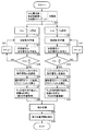
図10は、特許文献3に提案されている距離測定装置の構成を示す概略ブロック図である。
FIG. 10 is a schematic block diagram showing the configuration of the distance measuring device proposed in
図10を参照して、距離測定装置は、所定の周波数の信号を出力する発信源60と、発信源60の出力信号と同一周波数の電磁波を放出する送信部70と、送信部70から放出された電磁波(以下、進行波Dとも称する)と測定対象物M1〜Mn(nは自然数)にて反射した反射波Rとが干渉して形成された定在波Sの振幅を検知するための検出部80と、検出部80の検出信号から測定対象物Mk(kはn以下の自然数)までの距離を算出する信号処理部90とを備える。
Referring to FIG. 10, the distance measuring device emits a
発信源60は、発信部62と周波数制御部64とを含む。発信部62は、周波数制御部64が制御する一定の周波数fの信号を送信部70に対して出力する。周波数制御部64は、発信部62に送った周波数fに関する情報を信号処理部90にも出力する。
The
ここで、図10の距離測定装置における計測方式の原理について、簡単に説明する。
まず、図10に示すように、送信部70から放出された進行波Dと測定対象物Mkにて反射した反射波Rとが干渉することによって、送信部70と測定対象物Mkとの間の伝搬媒質中に定在波Sが形成される。
Here, the principle of the measurement method in the distance measuring apparatus of FIG. 10 will be briefly described.
First, as shown in FIG. 10, the traveling wave D emitted from the
このとき、定在波Sをx軸上の観測点xsに設けられた検出部80で観測して得られる受信パワー信号p(f,x)は、進行波Dの周波数fに対して正弦波関数(cos関数)となる。特に、複数の測定対象物からの反射がある場合には、各測定対象物に対応して互いに異なる周期の正弦波が複数合成されたものとなる。各正弦波の周期は、観測点から測定対象物Mkまでの距離に逆比例の関係にある。図10の距離測定装置は、この性質を利用して測定対象物Mkまでの距離を測定するものである。
At this time, the received power signal p (f, x) obtained by observing the standing wave S with the
すなわち、定在波Sは、送信部70から放出された進行波Dと、測定対象物Mkによる反射波Rとの加法的合成によって発生し、そのパワー信号p(f,x)は、次式で表わすことができる。
That is, the standing wave S is generated by additive synthesis of the traveling wave D emitted from the

ただし、cは光速、fは送信周波数、Aは進行波Dの振幅レベル、dkは測定対象物Mkまでの距離である。また、γkは測定対象物Mkの反射係数の大きさで伝搬損失を含む。φkは反射における位相シフト量である。 Here, c is the speed of light, f is the transmission frequency, A is the amplitude level of the traveling wave D, and d k is the distance to the measurement object M k . Γ k is the magnitude of the reflection coefficient of the measurement object M k and includes a propagation loss. φ k is a phase shift amount in reflection.
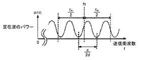
図11は、測定対象物Mkが距離dkの位置にあるときに、x=xs=0の位置で観測される受信パワー信号p(f,0)の波形図である。 FIG. 11 is a waveform diagram of the received power signal p (f, 0) observed at the position of x = x s = 0 when the measurement object M k is at the position of the distance d k .
図11を参照して、受信パワー信号p(f,0)は、送信周波数fに対して周期的であることが分かる。また、その周期はc/2dであって、測定対象物までの距離dに反比例することが分かる。したがって、この受信パワー信号p(f,0)をフーリエ変換して周期情報を抽出すれば、測定対象物までの距離dを求めることができる。なお、式(1)の受信パワー信号p(f,0)にフーリエ変換を適用して得られるプロファイルP(x)は、式(2)のようになる。 Referring to FIG. 11, it can be seen that the received power signal p (f, 0) is periodic with respect to the transmission frequency f. Also, it can be seen that the period is c / 2d and is inversely proportional to the distance d to the measurement object. Accordingly, if the received power signal p (f, 0) is Fourier-transformed to extract period information, the distance d to the measurement object can be obtained. Note that a profile P (x) obtained by applying Fourier transform to the received power signal p (f, 0) in Expression (1) is as shown in Expression (2).
ただし、 However,
f0は送信周波数帯域の中間周波数、fWは送信周波数の帯域幅である。
このように、図10の距離測定装置において、測定対象物Mkまでの距離dkは、進行波Dの送信周波数fに対する受信パワー信号p(f,0)の変動周期にのみ依存し、送信部70によって電磁波を発信してから検出部80に戻ってくるまでの時間の影響を受けないことから、これまでのFMCW方式およびパルス・レーダ方式に対して、近距離においても、より高い精度で測定することができる。
Thus, in the distance measuring apparatus of FIG. 10, the distance d k to the object of measurement M k depends only on the variation cycle of the reception power signal p (f, 0) with respect to the transmission frequency f of the traveling wave D, transmission Since it is not affected by the time from when the electromagnetic wave is transmitted by the
ここで、図10に示す従来の距離測定装置においては、定在波Sの受信パワー信号p(f,0)を式(2)にてフーリエ変換することから、送信周波数帯域幅fWにおいて、受信パワー信号p(f,x)に1周期以上の周期性がなければ、正確な周期情報を抽出することができない。 Here, in the conventional distance measuring apparatus shown in FIG. 10, the received power signal p (f, 0) of the standing wave S is Fourier-transformed by the equation (2), so that the transmission frequency bandwidth f W is If the received power signal p (f, x) does not have a periodicity of one cycle or more, accurate cycle information cannot be extracted.
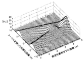
図12は、f0=24.0375GHz,fW=75MHz,γk=0.1,φk=πの条件下において、の測定対象物Mkの距離dkを0m≦dk≦5mの範囲で変化させたときの受信パワー信号のプロファイルの大きさ|P(x)|を式(1),(2)を用いて数値計算により求めたものである。なお、進行波のレベルA2を引いた、p(f,0)−A2をフーリエ変換しているので、式(1)の第1項は除去されている。 12, f 0 = 24.0375GHz, f W = 75MHz, under the conditions of γ k = 0.1, φ k = π, the distance d k of the measuring object M k of 0 m ≦ d k ≦ 5 m of The magnitude | P (x) | of the profile of the received power signal when changed in the range is obtained by numerical calculation using equations (1) and (2). Since p (f, 0) -A 2 obtained by subtracting the level A 2 of the traveling wave is Fourier transformed, the first term of the equation (1) is removed.
図12を参照して、プロファイルの大きさ|P(x)|は、式(2)の第2項の成分と第3項の成分とに対応して、xが正となる領域とxが負となる領域とにおいてそれぞれ極大値を有する波形となる。従来の距離測定装置においては、測定対象物Mkは必ずxが正の領域に位置することから、この波形のうちの一方の領域(x>0)の極大値を抽出し、極大値に対応するxの値を測定対象物Mkの位置としている。 Referring to FIG. 12, the profile size | P (x) | corresponds to the region where x is positive and x corresponds to the component of the second term and the component of the third term of Equation (2). Waveforms each having a maximum value in the negative region. In the conventional distance measuring apparatus, since the measurement object M k is always located in a region where x is positive, the maximum value of one region (x> 0) of this waveform is extracted and corresponds to the maximum value. The value of x to be used is the position of the measuring object Mk .
しかしながら、距離dが小さいときには、図12に示すように、プロファイルの大きさ|P(x)|のピークは正確な測定対象物Mkの位置を示さなくなる。これは、距離dが小さくなるに伴なって、2つの極大値が互いに干渉し合うことによって、波形が乱れてしまうことによる。図12の場合では、距離dが2m以上では正確に測距できるが、距離dが2mを下回ると、正しい計測値が得られていないことが分かる。 However, when the distance d is small, as shown in FIG. 12, the peak of the profile size | P (x) | does not indicate the exact position of the measurement object Mk . This is because, as the distance d becomes smaller, the two maximum values interfere with each other, thereby disturbing the waveform. In the case of FIG. 12, it can be seen that the distance can be accurately measured when the distance d is 2 m or more, but the correct measurement value is not obtained when the distance d is less than 2 m.
すなわち、従来の距離測定装置においては、xが負の領域に現れる極大値が、xが正の領域に現れる極大値に及ぼす影響(以下、負の周波数の影響とも称する。)に起因して、近距離における計測誤差の増加が問題となっていた。 That is, in the conventional distance measuring apparatus, the local maximum value where x appears in the negative region is affected by the local maximum value where x appears in the positive region (hereinafter also referred to as negative frequency effect). An increase in measurement error at a short distance has been a problem.
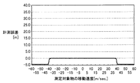
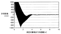
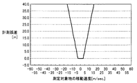
図13は、測定対象物Mkの距離dkが近距離レベル(〜10m)のときのプロファイルP(x)から得られる計測値と実際の測定対象物Mkまでの距離との関係を示す図である。なお、同図の関係は、測定条件として、送信部70から放出される進行波Dにおいて、送信周波数fの中心周波数f0を24.15GHzとし、送信周波数帯域幅fWを75MHzとしたときに得られたものである。
FIG. 13 shows the relationship between the measurement value obtained from the profile P (x) when the distance d k of the measurement object M k is a short distance level (−10 m) and the distance to the actual measurement object M k. FIG. The relationship shown in FIG. 6 is that when the traveling wave D emitted from the
図13を参照して、従来の距離測定装置から得られる計測値と実際の測定対象物Mkまでの距離dkとの間に生じる計測誤差は、測定対象物Mkまでの距離が短いほど、大きいことが分かる。具体的には、測定対象物Mkまでの距離が4m以上においては、計測値は実際の測定対象物Mkまでの距離に正確に一致しているが、4mを下回ると、計測誤差が急激に増加し始める。そして、測定対象物Mkまでの距離が2m以下となる領域では、計測誤差が1000mm程度にまで及び、測定精度が著しく劣ってしまうことが分かる。これは、近距離でのプロファイルP(x)の乱れによるものであり、2mが測距できる距離の限界であることを示唆している。 Referring to FIG. 13, the measurement error generated between the measurement value obtained from the conventional distance measuring device and the distance d k to the actual measurement object M k is smaller as the distance to the measurement object M k is shorter. It ’s big. Specifically, when the distance to the measurement object Mk is 4 m or more, the measurement value exactly matches the distance to the actual measurement object Mk. Begin to increase. And in the area | region where the distance to the measuring object Mk is 2 m or less, it turns out that a measurement error reaches about 1000 mm and measurement accuracy is remarkably inferior. This is due to the disturbance of the profile P (x) at a short distance, and suggests that 2 m is the limit of the distance that can be measured.
詳細には、距離dk=2mのときには、受信パワー信号p(f,0)の周期は、c/(2×2)=75MHzとなることから、送信周波数帯域幅fW=75MHzはちょうど受信パワー信号p(f,x)の1周期分の帯域に相当する。したがって、これより短い周期となるような、より長い距離dkであれば正しい計測値が得られることから、最小検出距離dminは、 Specifically, when the distance d k = 2m, the period of the reception power signal p (f, 0) is c / (2 × 2) = 75 MHz, so that the transmission frequency bandwidth f W = 75 MHz is just received. This corresponds to a band for one cycle of the power signal p (f, x). Therefore, since a correct measurement value can be obtained if the distance d k is longer than the shorter period d k , the minimum detection distance d min is
で表わすことができる。
ここで、先述のように、従来の距離測定装置を特定小電力無線として使用する場合は、使用できる周波数帯域幅が国内電波法によって制限される。たとえば「移動体検知センサ」においては、24.15GHz帯での周波数帯域を使用したとすると、占有周波数帯域幅の許容値は76MHzと規定される。したがって、図13の場合と同様に、約2m以下の近距離の位置計測において、計測結果に大きな誤差を生じることとなる。
It can be expressed as
Here, as described above, when the conventional distance measuring device is used as the specific low power radio, the usable frequency bandwidth is limited by the domestic radio law. For example, in the “moving body detection sensor”, if the frequency band in the 24.15 GHz band is used, the allowable value of the occupied frequency bandwidth is defined as 76 MHz. Therefore, as in the case of FIG. 13, a large error occurs in the measurement result in the position measurement at a short distance of about 2 m or less.
以上に述べた計測誤差は、受信パワー信号p(f,x)が1周期成分以下となる近距離に特有の問題点であるが、1周期成分以上の周期性が含まれる距離(中距離および遠距離)の場合であっても、以下に示すように数mm程度の計測誤差が生じうる。 The measurement error described above is a problem peculiar to a short distance in which the received power signal p (f, x) is equal to or less than one period component, but a distance (medium distance and Even in the case of a long distance), a measurement error of about several millimeters can occur as shown below.
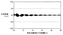
図14は、測定対象物Mkの距離dkが遠距離レベル(〜20m)のときのプロファイルP(x)から得られる計測値と実際の測定対象物Mkまでの距離との関係を示す図である。なお、同図の関係は、測定条件として、送信部70から放出される進行波Dにおいて、送信周波数fの中心周波数f0を24.15GHzとし、送信周波数帯域幅fWを75MHzとしたときに得られたものである。
FIG. 14 shows the relationship between the measured value obtained from the profile P (x) when the distance d k of the measuring object M k is a long distance level (˜20 m) and the distance to the actual measuring object M k. FIG. The relationship shown in FIG. 6 is that when the traveling wave D emitted from the
図14を参照して、測定対象物Mkを遠距離レベルである距離dk=10mからdk=20mまで位置変化させたときには、計測結果に最大±2mm程度の誤差が生じていることが分かる。この誤差の一因としては、フーリエ変換における窓関数の窓長が受信パワー信号p(f,0)の波長の整数倍になっていないことが挙げられる。 Referring to FIG. 14, when the position of measurement object M k is changed from a distance d k = 10 m, which is a long distance level, to d k = 20 m, an error of about ± 2 mm at maximum occurs in the measurement result. I understand. One cause of this error is that the window length of the window function in the Fourier transform is not an integral multiple of the wavelength of the received power signal p (f, 0).
また、中距離および遠距離においては、受信パワー信号p(f,0)に周期性があるにも関わらず、測定対象物Mkが微小に位置変化した場合においても、計測誤差が生じる。 At medium and long distances, a measurement error occurs even when the position of the measurement object Mk is slightly changed despite the periodicity of the received power signal p (f, 0).
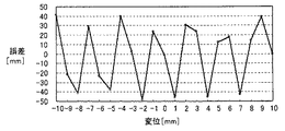
図15は、測定対象物Mkを距離dk=10mの位置を基準として、±10mmの範囲内で微小に位置変化させたときの計測誤差を示す図である。 FIG. 15 is a diagram illustrating a measurement error when the position of the measurement object M k is minutely changed within a range of ± 10 mm with respect to the position of the distance d k = 10 m.
図15から明らかなように、測定対象物Mkが当該距離測定装置から遠距離であって、受信パワー信号p(f,0)に十分な周期性が見られる距離dk=10mの地点に位置するときにおいても、計測結果には、約±5cm程度の誤差が生じている。 As is clear from FIG. 15, the measurement object M k is a long distance from the distance measurement device, and the distance d k = 10 m at which sufficient periodicity is seen in the received power signal p (f, 0). Even when positioned, an error of about ± 5 cm occurs in the measurement result.
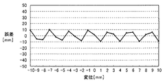
ここで、この計測誤差を低減する手段としては、第1に、受信パワー信号p(f,0)をフーリエ変換する際に、受信パワー信号p(f,0)から少なくとも1周期成分が含まれる信号範囲を抽出してフーリエ変換することを、少なくとも半周期成分以上の範囲で繰り返し、その各フーリエ変換されたデータから各時間領域の和を求めることが挙げられる。 Here, as means for reducing the measurement error, first, when the received power signal p (f, 0) is Fourier-transformed, at least one period component is included from the received power signal p (f, 0). Extracting the signal range and performing Fourier transform may be repeated at least in a range equal to or greater than a half-period component, and the sum of each time domain may be obtained from the Fourier-transformed data.
第2に、送信周波数fの使用帯域幅fWは同一とし、送信する初期の周波数をわずかにずらせることによって得られた受信パワー信号をフーリエ変換することを、少なくとも半周期成分以上の範囲で繰り返し、その各フーリエ変換されたデータから各時間領域の和を求めることが挙げられる。 Second, the use bandwidth f W of the transmission frequency f is the same, and the received power signal obtained by slightly shifting the initial transmission frequency is Fourier-transformed in a range of at least a half cycle component or more. Repeatedly, the sum of each time domain is obtained from the Fourier transformed data.
図16は、受信パワー信号p(f,0)をこれらの手段に従って多重処理したときの処理結果である。図16から明らかなように、計測結果に見られる誤差は、変位が±10mmに至る範囲において、約±1cm程度にまで改善される。 FIG. 16 shows a processing result when the received power signal p (f, 0) is multiplexed according to these means. As apparent from FIG. 16, the error seen in the measurement result is improved to about ± 1 cm in the range where the displacement reaches ± 10 mm.
しかしながら、このような多重処理は、複数のフーリエ変換処理を含むことから、処理に相当な時間が必要となり、即応性を必要とする用途には不向きであるという問題点を有する。 However, since such multiple processing includes a plurality of Fourier transform processes, it takes a considerable amount of time for the processing, and thus has a problem that it is not suitable for applications that require quick response.
さらに、図10の距離測定装置では、測定対象物Mkが等速で計測軸(x軸)上を移動している場合においても、計測結果に誤差が生じるという問題がある。 Furthermore, the distance measuring apparatus of FIG. 10 has a problem that an error occurs in the measurement result even when the measurement object Mk is moving on the measurement axis (x axis) at a constant speed.
詳細には、測定対象物Mkが移動している場合、検出部80で検出される定在波Sの受信パワー信号p(f,0)においては、受信周波数が送信周波数fに対して伝搬媒質の時間的変化に比例した周波数だけシフトするという、ドップラーシフトが生じる。このときのシフト量は、測定対象物Mkが接近する場合には受信周波数を下げる方向に作用し、測定対象物Mkが離れる場合では受信周波数を上げる方向に作用する。
Specifically, when the measurement object Mk is moving, in the reception power signal p (f, 0) of the standing wave S detected by the
たとえば、所定の距離dk=10mに位置する測定対象物Mkが一定の速度で等速移動しているものとする。そして、従来の距離測定装置は、送信部70において、使用帯域幅内で送信周波数fを上昇させながら掃引する上昇掃引と、使用帯域幅内で送信周波数fを下降させながら掃引する下降掃引とをそれぞれ行なうものとする。
For example, it is assumed that the measuring object M k located at a predetermined distance d k = 10 m is moving at a constant speed. In the conventional distance measuring apparatus, the
このとき、測定対象物Mkの移動方向と送信周波数fの掃引方向とにより、受信パワー信号p(f,0)には周期性に以下のような現象が生じる。詳細には、上昇掃引の場合は、測定対象物Mkが接近するときには周期性が長くなり、測定対象物Mkが遠ざかるときには周期性が短くなる。一方、下降掃引の場合は、測定対象物Mkが接近するときには周期性が短くなり、測定対象物Mkが遠ざかるときには周期性が長くなる。 At this time, the following phenomenon occurs in the periodicity in the received power signal p (f, 0) depending on the moving direction of the measurement object Mk and the sweeping direction of the transmission frequency f. Specifically, in the upward sweep, the periodicity becomes longer when the measuring object Mk approaches, and the periodicity becomes shorter when the measuring object Mk moves away. On the other hand, in the downward sweep, the periodicity is short when the measuring object Mk approaches, and the periodicity is long when the measuring object Mk moves away.
そして、いずれの掃引方向においても、周期性が長くなると、送信周波数帯域幅fWにおいて、受信パワー信号p(f,0)に1周期以上の周期性が得られず、上述した負の周波数の影響による計測誤差を増加させてしまう。 In any sweep direction, if the periodicity becomes longer, the received power signal p (f, 0) cannot have a periodicity of one period or more in the transmission frequency bandwidth f W , and the negative frequency described above is not obtained. Increases measurement error due to influence.
さらに、このときの計測誤差は、上述したドップラーシフトの影響により、上昇掃引と下降掃引とのいずれの掃引方向においても、測定対象物Mkの移動速度が増加するにつれ、実際の測定対象物Mkの位置(10m)に対する誤差が大きくなる。 Further, the measurement error at this time is the actual measurement object M as the moving speed of the measurement object Mk increases in any of the upward sweep and the downward sweep due to the influence of the Doppler shift described above. The error with respect to the position of k (10 m) becomes large.
このような計測誤差を低減する手段としては、送信周波数fを上昇掃引して得られる受信パワー信号p(f,0)をフーリエ変換して得られる計測結果(以下、第1の位置情報とも称する)と、送信周波数fを下降掃引して得られる受信パワー信号p(f,0)をフーリエ変換して得られる計測結果(以下、第2の位置情報とも称する)とを求め、第1および第2の位置情報を平均化する補正処理を行なうことによって、移動する測定対象物の位置を検出する方法が挙げられる。 As a means for reducing such a measurement error, a measurement result (hereinafter also referred to as first position information) obtained by Fourier-transforming the received power signal p (f, 0) obtained by increasing and sweeping the transmission frequency f. ) And a measurement result (hereinafter also referred to as second position information) obtained by performing Fourier transform on the received power signal p (f, 0) obtained by sweeping down the transmission frequency f. There is a method of detecting the position of the moving measurement object by performing a correction process for averaging the position information of the two.
この方法に従って補正処理をした結果を図17に示す。図17を参照して、掃引時間が10m秒のときにおいては、移動速度がおよそ±2m/s以下となる範囲において、計測誤差が0mに保たれている。しかしながら、移動速度がこの範囲を超えて増加するに従って計測誤差が大きくなることが分かる。これは、上述した負の周波数の影響に起因するものである。すなわち、従来の距離測定装置では、プロファイルの大きさ|P(x)|の波形において、xが正となる領域の極大値のみを一様に抽出することから、測定対象物Mkが遠ざかる方向に高速に移動し、xが負となる領域に存在する場合を正確に検出できないことによる。 The result of correction processing according to this method is shown in FIG. Referring to FIG. 17, when the sweep time is 10 msec, the measurement error is kept at 0 m in the range where the moving speed is about ± 2 m / s or less. However, it can be seen that the measurement error increases as the moving speed increases beyond this range. This is due to the negative frequency effect described above. That is, in the conventional distance measuring device, only the local maximum value in the region where x is positive is uniformly extracted in the waveform of the profile size | P (x) |, and thus the measurement object Mk moves away. This is because it cannot be detected accurately when it is in a region where x moves negatively and x is negative.
なお、図示は省略するが、掃引時間をより短くすることによって、正しい測定対象物Mkの位置が得られるときの移動速度の範囲はさらに拡大される。 Although illustration is omitted, the range of the moving speed when the correct position of the measuring object Mk is obtained is further expanded by shortening the sweep time.
しかしながら、このような方法では、補正処理ができる測定対象物Mkの移動速度の範囲が、送信周波数fの掃引時間に依存することから、高速で移動する測定対象物Mkを対象とするときには、掃引時間を一層短く、すなわち掃引速度を高速にしなければならない。そのためには、安定して高速可変が可能な発振器が新たに必要となる。 However, in such a method, since the range of the moving speed of the measuring object M k that can be corrected depends on the sweep time of the transmission frequency f, when the measuring object M k that moves at high speed is targeted. The sweep time must be shorter, i.e., the sweep speed must be increased. For this purpose, an oscillator that can be stably and rapidly varied is required.
それゆえ、この発明のある目的は、狭い放射周波数帯域においても、近距離まで精度良く計測可能な距離測定装置、距離測定方法および距離測定プログラムを提供することである。 Therefore, an object of the present invention is to provide a distance measuring device, a distance measuring method, and a distance measuring program capable of accurately measuring a short distance even in a narrow radiation frequency band.
この発明の別の目的は、移動する測定対象物においても、正確に測距可能な距離測定装置、距離測定方法および距離測定プログラムを提供することである。 Another object of the present invention is to provide a distance measuring device, a distance measuring method, and a distance measuring program capable of accurately measuring even a moving measurement object.
この発明によれば、測定対象物までの距離を計測する距離測定装置は、周波数が可変である送信信号を出力する発信源と、送信信号と同一周波数の電磁波を発生し、測定対象物に対して放射する送信部と、電磁波の反射波を検出する検出部と、検出された反射波と送信周波数との関係を演算処理することによって測定対象物までの距離を算出する信号処理部とを備える。検出部は、検出された反射波を送信信号により同期検波して反射波の位相変化成分を抽出する検波手段を含む。信号処理部は、抽出された位相変化成分の変動周波数を、所定の距離に応じた周波数だけ変化させる周波数変換手段と、周波数変換手段により得られる上側帯波および下側帯波のうちの一方を解析信号とする解析信号生成手段と、解析信号をフーリエ変換してプロファイルを算出し、プロファイルの極大値と所定の距離とに基づいて測定対象物までの距離を求めるフーリエ変換手段とを含む。 According to the present invention, a distance measuring device for measuring a distance to a measurement object generates a transmission signal that outputs a transmission signal having a variable frequency, and generates an electromagnetic wave having the same frequency as the transmission signal. And a transmitting unit that radiates the electromagnetic wave, a detecting unit that detects a reflected wave of the electromagnetic wave, and a signal processing unit that calculates a distance to the measurement object by calculating a relationship between the detected reflected wave and the transmission frequency. . The detection unit includes detection means for extracting the phase change component of the reflected wave by synchronously detecting the detected reflected wave using the transmission signal. The signal processing unit analyzes a frequency conversion unit that changes the fluctuation frequency of the extracted phase change component by a frequency corresponding to a predetermined distance, and one of the upper sideband and the lower sideband obtained by the frequency conversion unit. An analysis signal generation unit that is a signal, and a Fourier transform unit that calculates a profile by Fourier transforming the analysis signal and obtains a distance to the measurement object based on the maximum value of the profile and a predetermined distance.
好ましくは、発信源は、所定の送信周波数を所定の帯域幅で所定のステップで上昇させて掃引する上昇掃引手段と、所定の送信周波数を所定の帯域幅で所定のステップで下降させて掃引する下降掃引手段とを含む。信号処理部は、上昇掃引手段に応じてフーリエ変換手段にて得られる測定対象物までの距離を第1の位置情報とし、下降掃引手段に応じてフーリエ変換手段にて得られる測定対象物までの距離を第2の位置情報として保持する手段と、保持された第1および第2の位置情報を平均化して真の測定対象物までの距離を導出する補正手段とをさらに含む。 Preferably, the transmission source sweeps up the predetermined transmission frequency by increasing the predetermined bandwidth at a predetermined step in a predetermined step and the predetermined transmission frequency by decreasing the predetermined transmission frequency by a predetermined step. And descending sweep means. The signal processing unit uses the distance to the measurement object obtained by the Fourier transform unit according to the ascending sweep means as the first position information, and the distance to the measurement object obtained by the Fourier transform means according to the descending sweep means. It further includes means for holding the distance as the second position information, and correction means for averaging the held first and second position information to derive the distance to the true measurement object.
好ましくは、検波手段は、反射波を送信信号により同期検波して位相変化成分の同相成分を抽出し、反射波を送信信号とπ/2位相が異なる信号により同期検波して位相変化成分の直交成分を抽出する。 Preferably, the detection means detects the reflected wave synchronously with the transmission signal to extract an in-phase component of the phase change component, and detects the reflected wave synchronously with a signal having a phase difference of π / 2 from that of the transmission signal to orthogonally intersect the phase change component. Extract ingredients.
好ましくは、所定の距離は、所定の送信周波数を所定の帯域幅で掃引させるときの分割数に応じて可変とする。 Preferably, the predetermined distance is variable in accordance with the number of divisions when a predetermined transmission frequency is swept with a predetermined bandwidth.
好ましくは、所定の距離は、所定の帯域幅と分割数とから決まる最大検出可能距離の略半分を最大値とするように設定される。 Preferably, the predetermined distance is set so that the maximum value is approximately half of the maximum detectable distance determined from the predetermined bandwidth and the number of divisions.
好ましくは、検波手段は、包絡線検波した反射波から送信信号の直流成分を差し引くことにより反射波の位相変化成分を抽出する。 Preferably, the detection means extracts the phase change component of the reflected wave by subtracting the direct current component of the transmission signal from the reflected wave detected by the envelope.
この発明によれば、測定対象物までの距離を計測する距離測定方法は、周波数が可変である信号を出力するステップと、信号と同一周波数の電磁波を発生し、測定対象物に対して放射するステップと、電磁波の反射波を検出するステップと、検出した反射波と送信周波数との関係を演算処理することによって測定対象物までの距離を算出するステップとを備える。反射波を検出するステップは、検出された反射波を送信信号により同期検波して反射波の位相変化成分を抽出するステップを含む。測定対象物までの距離を算出するステップは、抽出された位相変化成分の変動周波数を、所定の距離に応じた周波数だけ変化させるステップと、周波数を変化させて得られる上側帯波および下側帯波のうちの一方を解析信号とするステップと、解析信号をフーリエ変換してプロファイルを算出し、プロファイルの極大値と所定の距離とに基づいて測定対象物までの距離を求めるステップとを含む。 According to the present invention, a distance measuring method for measuring a distance to a measurement object generates a signal having a variable frequency, generates an electromagnetic wave having the same frequency as the signal, and radiates the electromagnetic wave to the measurement object. A step, a step of detecting a reflected wave of the electromagnetic wave, and a step of calculating a distance to the measurement object by calculating a relationship between the detected reflected wave and the transmission frequency. The step of detecting the reflected wave includes a step of synchronously detecting the detected reflected wave with a transmission signal and extracting a phase change component of the reflected wave. The step of calculating the distance to the measurement object includes a step of changing the fluctuation frequency of the extracted phase change component by a frequency corresponding to a predetermined distance, and an upper side band and a lower side band wave obtained by changing the frequency. And a step of calculating a profile by Fourier transforming the analysis signal and obtaining a distance to the measurement object based on the maximum value of the profile and a predetermined distance.
好ましくは、周波数が可変である信号を出力するステップは、所定の送信周波数を所定の帯域幅で所定のステップで上昇させて掃引するステップと、所定の送信周波数を所定の帯域幅で所定のステップで下降させて掃引するステップとを含む。測定対象物までの距離を算出するステップは、上昇掃引したときにフーリエ変換にて得られる測定対象物までの距離を第1の位置情報とし、下降掃引したときにフーリエ変換にて得られる測定対象物までの距離を第2の位置情報として保持するステップと、保持された第1および第2の位置情報を平均化して真の測定対象物までの距離を導出するステップとをさらに含む。 Preferably, the step of outputting a signal having a variable frequency includes a step of increasing a predetermined transmission frequency by a predetermined bandwidth with a predetermined bandwidth and sweeping, and a predetermined step with the predetermined transmission frequency having a predetermined bandwidth. And descending and sweeping. The step of calculating the distance to the measurement object uses the distance to the measurement object obtained by the Fourier transform when the up sweep is performed as the first position information, and the measurement object obtained by the Fourier transform when the down sweep is performed. The method further includes the step of holding the distance to the object as the second position information, and the step of deriving the distance to the true measurement object by averaging the held first and second position information.
好ましくは、反射波の位相変化成分を抽出するステップは、反射波を送信信号により同期検波して位相変化成分の同相成分を抽出し、反射波を送信信号とπ/2位相が異なる信号により同期検波して位相変化成分の直交成分を抽出する。 Preferably, in the step of extracting the phase change component of the reflected wave, the reflected wave is synchronously detected by the transmission signal to extract an in-phase component of the phase change component, and the reflected wave is synchronized by a signal having a phase difference of π / 2 from the transmission signal. Detection is performed to extract a quadrature component of the phase change component.
好ましくは、所定の距離は、所定の送信周波数を所定の帯域幅で掃引させるときの分割数に応じて可変とする。 Preferably, the predetermined distance is variable in accordance with the number of divisions when a predetermined transmission frequency is swept with a predetermined bandwidth.
好ましくは、所定の距離は、所定の帯域幅と分割数とから決まる最大検出可能距離の略半分を最大値とするように設定される。 Preferably, the predetermined distance is set so that the maximum value is approximately half of the maximum detectable distance determined from the predetermined bandwidth and the number of divisions.
好ましくは、反射波の位相変化成分を抽出するステップは、包絡線検波した反射波から送信信号の直流成分を差し引くことにより反射波の位相変化成分を抽出する。 Preferably, the step of extracting the phase change component of the reflected wave extracts the phase change component of the reflected wave by subtracting the direct current component of the transmission signal from the reflected wave detected by the envelope detection.
この発明によれば、測定対象物までの距離を計測する距離測定プログラムは、コンピュータに、周波数が可変である信号を出力するステップと、信号と同一周波数の電磁波を発生し、測定対象物に対して放射するステップと、電磁波の反射波を検出するステップと、検出した反射波と送信周波数との関係を演算処理することによって測定対象物までの距離を算出するステップとを実行させる。反射波を検出するステップは、検出された反射波を送信信号により同期検波して反射波の位相変化成分を抽出するステップを含む。測定対象物までの距離を算出するステップは、抽出された位相変化成分の変動周波数を、所定の距離に応じた周波数だけ変化させるステップと、周波数を変化させて得られる上側帯波および下側帯波のうちの一方を解析信号とするステップと、解析信号をフーリエ変換してプロファイルを算出し、プロファイルの極大値と所定の距離とに基づいて測定対象物までの距離を求めるステップとを含む。 According to this invention, the distance measurement program for measuring the distance to the measurement object generates a signal having a variable frequency to the computer, generates an electromagnetic wave having the same frequency as the signal, and outputs the electromagnetic wave to the measurement object. And the step of detecting the reflected wave of the electromagnetic wave, and the step of calculating the distance to the measurement object by calculating the relationship between the detected reflected wave and the transmission frequency. The step of detecting the reflected wave includes a step of synchronously detecting the detected reflected wave with a transmission signal and extracting a phase change component of the reflected wave. The step of calculating the distance to the measurement object includes a step of changing the fluctuation frequency of the extracted phase change component by a frequency corresponding to a predetermined distance, and an upper side band and a lower side band wave obtained by changing the frequency. And a step of calculating a profile by Fourier transforming the analysis signal and obtaining a distance to the measurement object based on the maximum value of the profile and a predetermined distance.
好ましくは、周波数が可変である信号を出力するステップは、所定の送信周波数を所定の帯域幅で所定のステップで上昇させて掃引するステップと、所定の送信周波数を所定の帯域幅で所定のステップで下降させて掃引するステップとを含む。測定対象物までの距離を算出するステップは、上昇掃引したときにフーリエ変換にて得られる測定対象物までの距離を第1の位置情報とし、下降掃引したときにフーリエ変換にて得られる測定対象物までの距離を第2の位置情報として保持するステップと、保持された第1および第2の位置情報を平均化して真の前記測定対象物までの距離を導出するステップとをさらに含む。 Preferably, the step of outputting a signal having a variable frequency includes a step of increasing a predetermined transmission frequency by a predetermined bandwidth with a predetermined bandwidth and sweeping, and a predetermined step with the predetermined transmission frequency having a predetermined bandwidth. And descending and sweeping. The step of calculating the distance to the measurement object uses the distance to the measurement object obtained by the Fourier transform when the up sweep is performed as the first position information, and the measurement object obtained by the Fourier transform when the down sweep is performed. The method further includes the step of holding the distance to the object as the second position information, and the step of deriving the true distance to the measurement object by averaging the held first and second position information.
好ましくは、反射波の位相変化成分を抽出するステップは、反射波を送信信号により同期検波して位相変化成分の同相成分を抽出し、反射波を送信信号とπ/2位相が異なる信号により同期検波して位相変化成分の直交成分を抽出する。 Preferably, in the step of extracting the phase change component of the reflected wave, the reflected wave is synchronously detected by the transmission signal to extract an in-phase component of the phase change component, and the reflected wave is synchronized by a signal having a phase difference of π / 2 from the transmission signal. Detection is performed to extract a quadrature component of the phase change component.
好ましくは、所定の距離は、所定の送信周波数を所定の帯域幅で掃引させるときの分割数に応じて可変とする。 Preferably, the predetermined distance is variable in accordance with the number of divisions when a predetermined transmission frequency is swept with a predetermined bandwidth.
好ましくは、所定の距離は、所定の帯域幅と分割数とから決まる最大検出可能距離の略半分を最大値とするように設定される。 Preferably, the predetermined distance is set so that the maximum value is approximately half of the maximum detectable distance determined from the predetermined bandwidth and the number of divisions.
好ましくは、反射波の位相変化成分を抽出するステップは、包絡線検波した反射波から送信信号の直流成分を差し引くことにより反射波の位相変化成分を抽出する。 Preferably, the step of extracting the phase change component of the reflected wave extracts the phase change component of the reflected wave by subtracting the direct current component of the transmission signal from the reflected wave detected by the envelope detection.
この発明によれば、制限された送信周波数帯域幅においても、測定対象物を距離0mから高い測定精度で測距可能な距離測定装置を実現することができる。 According to the present invention, it is possible to realize a distance measuring apparatus capable of measuring a measurement object from a distance of 0 m with high measurement accuracy even in a limited transmission frequency bandwidth.
さらに、測定対象物が高速移動しているときにおいても、送信周波数を上昇掃引および下降掃引して得られる計測結果に補正処理を施すことにより、掃引時間に依存せず、精度良く測距することができる。 In addition, even when the measurement object is moving at high speed, it is possible to accurately measure the distance without depending on the sweep time by applying correction processing to the measurement result obtained by sweeping the transmission frequency up and down. Can do.
以下、この発明の実施の形態について図面を参照して詳しく説明する。なお、図中同一符号は同一または相当部分を示す。 Hereinafter, embodiments of the present invention will be described in detail with reference to the drawings. In the drawings, the same reference numerals indicate the same or corresponding parts.
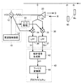
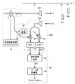
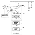
図1は、この発明の実施の形態に従う距離測定装置の基本構成を示す回路図である。
図1を参照して、距離測定装置は、一定の送信周波数fの送信信号を発信する発信源10と、発信された送信信号と同一の周波数fの電磁波を放出する送信部20と、送信部20から出力された電磁波(以下、進行波Dとも称する)が測定対象物M1〜Mnにおいてそれぞれ反射されたときの電磁波(以下、反射波Rとも称する)を検出する検出部30と、検出部30で検出された反射波Rを演算処理し、測定対象物M1〜Mnとの距離d1〜dnを算出する信号処理部40とを備える。
FIG. 1 is a circuit diagram showing a basic configuration of a distance measuring apparatus according to an embodiment of the present invention.
Referring to FIG. 1, a distance measuring apparatus includes a
発信源10は、一定の周波数fの送信信号を出力する発信部12と、発信部12の出力する送信信号の周波数fを制御する周波数制御部14とを含む。
The
発信部12は、たとえば電圧制御発振回路(VCO:Voltage Controlled Oscillator)で構成され、周波数制御部14からの制御信号に基づいて、所定の送信周波数fの送信信号を出力する。
The
周波数制御部14は、たとえば位相検出器で構成され、信号処理部40からの基準発振信号と発信部12から帰還される帰還信号との位相差を検出し、VCOの発振周波数を上昇または下降させる制御信号を出力する。
The
発信部12では、VCOがこの制御信号を受けて発振周波数を調整することにより、基準発振信号に対して周波数と位相とが一致し、かつ所定の送信周波数fに制御された送信信号が出力される。
In the
送信部20は、たとえばアンテナで構成され、アンテナと測定対象物M1〜Mnとの間に存在する空気や水などの伝搬媒質中もしくは真空中に、発信部12の出力信号と同一周波数fの電磁波を計測軸(x軸)方向に放出する。
The
検出部30は、方向性結合器32と、乗算器34,35と、ローパスフィルタ(LPF)36,37と、π/2移相器38とを含む。
The
方向性結合器32は、x軸上のx=0の地点に位置するように配される。方向性結合器32は、送信部20のアンテナで受信された信号から反射波Rを検出し、その検出した反射波Rを乗算器34,35の一方入力へそれぞれ出力する。
The
乗算器34,35の他方入力には、発信部12であるVCOから送信周波数fの送信信号がそれぞれ与えられる。このとき、乗算器35の他方入力には、発信部12からの送信信号をπ/2移相器38でπ/2だけ位相シフトして得られる信号が与えられる。
The other input of the
これにより、乗算器34,35においては、反射波Rと送信信号に同期した信号とを積算することによる検波、いわゆる同期検波が行なわれる。そして、乗算器34からは、これら2つの入力信号の乗算結果として、検波信号の同相(I相)成分I(f,t)が出力される。また、乗算器35からは、これら2つの入力信号の乗算結果として、検波信号の直交(Q相)成分Q(f,t)が出力される。
Thus, the
そして、検波信号の同相成分I(f,t)と直交成分Q(f,t)とがLPF36,37にそれぞれ与えられると、高周波成分が除去されて、直流成分I(f),Q(f)が抽出される。抽出された直流成分I(f),Q(f)は、信号処理部40へ出力される。
When the in-phase component I (f, t) and the quadrature component Q (f, t) of the detection signal are applied to the
信号処理部40は、検出部30に接続され、反射波Rの直流成分I(f),Q(f)を受ける。
The
信号処理部40は、反射波Rの直流成分I(f),Q(f)から解析信号p(f)を生成する解析信号生成部42と、生成された解析信号p(f)をフーリエ変換してプロファイルP(x)を算出するフーリエ変換部44とを含む。なお、解析信号生成部42とフーリエ変換部44とは、たとえばデジタルシグナルプロセッサ(DSP:Digital Signal Processor)によって一体的に構成される。これにより、各部における演算処理は、予め記憶されたプログラムにしたがってソフトウェア的に実行される。
The
以上のように、本実施の形態に係る距離測定装置の構成は、図10に示す従来の距離測定装置に対して、基本的な構成を同じくする。しかしながら、検出部30において反射波Rを検出する点と、信号処理部40に解析信号生成部42を含む点とにおいて、従来の距離測定装置とは異なる。以下に、本実施の形態に従う距離測定方法について詳細に説明し、上記の相違点のもたらす効果について明示する。
As described above, the configuration of the distance measuring device according to the present embodiment is the same as the basic configuration of the conventional distance measuring device shown in FIG. However, the
最初に、本実施の形態に従う距離測定方法の測定原理について説明する。
図1に示す距離測定装置において、送信部20から放出された進行波Dが時刻tにおいて、
First, the measurement principle of the distance measurement method according to the present embodiment will be described.
In the distance measuring apparatus shown in FIG. 1, the traveling wave D emitted from the
![]()
![]()
で表わされるとき、各測定対象物までの距離をdkとすれば、各測定対象物Mkによる反射波Rは、次のように表わすことができる。 If the distance to each measurement object is d k , the reflected wave R by each measurement object M k can be expressed as follows.
ただし、cは光速、fは送信周波数、Aは進行波Dの振幅レベル、dkは測定対象物Mkまでの距離である。また、γkは測定対象物Mkの反射係数の大きさで伝搬損失を含む。φkは反射における位相シフト量である。 Here, c is the speed of light, f is the transmission frequency, A is the amplitude level of the traveling wave D, and d k is the distance to the measurement object M k . Γ k is the magnitude of the reflection coefficient of the measurement object M k and includes a propagation loss. φ k is a phase shift amount in reflection.
そして、検出部30の乗算器34,35において、式(6)の反射波Rを、送信周波数fの送信信号とこれとπ/2位相が異なる送信信号の直交信号とでそれぞれ同期検波することにより、次式で示す検波信号の同相成分I(f,t)と直交成分Q(f,t)とが得られる。
Then, in the
さらに、式(7)の同相成分I(f,t)および直交成分Q(f,t)から、LPF36,37を介して高周波成分(送信信号の2倍波成分に相当)を除去することによって、直流成分I(f),Q(f)が抽出される。 Further, by removing the high frequency component (corresponding to the second harmonic component of the transmission signal) from the in-phase component I (f, t) and the quadrature component Q (f, t) of the equation (7) through the LPFs 36 and 37. DC components I (f) and Q (f) are extracted.
ここで、式(8)を参照して、直流成分I(f),Q(f)は、式(7)で表わされる反射波Rの検波信号から、進行波Dが測定対象物Mkで反射したときの位相シフト量φkの変化分(以下、位相変化成分とも称する)を抽出したものであることが分かる。すなわち、式(8)の直流成分は、測定対象物Mkまでの距離dkに応じた周期で変動する関数となる。したがって、この直流成分をフーリエ変換することによって周期成分を抽出すれば、距離dkが分かる。 Here, with reference to Equation (8), the DC components I (f) and Q (f) are generated from the detection signal of the reflected wave R represented by Equation (7), and the traveling wave D is the measurement object Mk . It can be seen that the change amount of the phase shift amount φ k when reflected (hereinafter also referred to as a phase change component) is extracted. That is, the direct current component of the equation (8) is a function that varies with a period according to the distance d k to the measurement object M k . Therefore, if the periodic component is extracted by Fourier transforming this DC component, the distance d k can be found.
式(8)に示す直流成分は、それぞれ実信号として、次式で示すcos関数とsin関数とで表される。 The direct current component shown in Expression (8) is expressed as a real signal by a cos function and a sin function expressed by the following expressions, respectively.
したがって、式(9),(10)を同相成分および直交成分とする複素正弦波関数を受信パワー信号p(f)とし、これをフーリエ変換して得られるプロファイルの大きさ|P(x)|の極大値に基づいて測定対象物Mkまでの距離dkが得られると予想される。 Accordingly, the complex sine wave function having the in-phase component and the quadrature component as equations (9) and (10) is the received power signal p (f), and the magnitude of the profile | P (x) | It is expected that the distance d k to the measurement object M k can be obtained based on the local maximum value.
しかしながら、式(9),(10)からなる複素正弦波関数をフーリエ変換したプロファイルP(x)には、上記の式(2)のプロファイルP(x)と同様に、e+jθ(f)に起因する第2項と、e-jθ(f)に起因する第3項とが発生する(θ(f)は位相変化成分)。そのため、図12で示したのと同様に、距離dが小さいときには、プロファイルの大きさ|P(x)|において、第2項および第3項にそれぞれ対応する2つの極大値が互いに干渉し合うことによって、計測誤差が増加することになる。すなわち、負の周波数の影響を回避できないことから、測定対象物が近距離に位置するとき、および測定対象物が移動体であるときの計測誤差を低減することができない。 However, in the profile P (x) obtained by Fourier transforming the complex sine wave function composed of the equations (9) and (10), similarly to the profile P (x) in the above equation (2), e + jθ (f) The resulting second term and the third term resulting from e −jθ (f) are generated (θ (f) is a phase change component). Therefore, as shown in FIG. 12, when the distance d is small, the two maximum values respectively corresponding to the second term and the third term interfere with each other in the profile size | P (x) | As a result, the measurement error increases. That is, since the influence of the negative frequency cannot be avoided, measurement errors when the measurement object is located at a short distance and when the measurement object is a moving object cannot be reduced.
そこで、この発明による距離測定装置は、式(9),(10)からなる複素正弦波関数の周期性が、負の周波数の影響を受けない距離に応じた周期性となるように、周波数変換させることを特徴とする。 Therefore, the distance measuring apparatus according to the present invention converts the frequency so that the periodicity of the complex sine wave function consisting of the equations (9) and (10) becomes a periodicity corresponding to the distance not affected by the negative frequency. It is characterized by making it.
詳細には、式(9),(10)を同相成分および直交成分とする、距離dkに応じた周期性を持つ実信号と、予め設定された所定の距離d0に応じた周期性を持つ信号I0(f),Q0(f)とを混成(ミキシング)する。信号I0(f),Q0(f)をそれぞれ、 More specifically, the real signal having the periodicity according to the distance d k and the periodicity according to the predetermined distance d 0 set in advance using the equations (9) and (10) as the in-phase component and the quadrature component. The signals I 0 (f) and Q 0 (f) are mixed (mixed). Signals I 0 (f) and Q 0 (f) are respectively
とすると、式(9),(10)の実信号と式(11),(12)とをミキシングすることによって、次式で示される解析信号p(f)が生成される。 Then, by mixing the real signals of equations (9) and (10) with equations (11) and (12), an analysis signal p (f) represented by the following equation is generated.
すなわち、式(13)の解析信号p(f)は、送信周波数fに対して周期的であり、その周期性は、所定の距離d0に応じた周期性よりも距離dkに応じた周期性だけ高い信号となる。 That is, the analysis signal p (f) of the expression (13) is periodic with respect to the transmission frequency f, and the periodicity is a period according to the distance d k rather than a periodicity according to the predetermined distance d 0. It becomes a signal that is only high in nature.
ここで、距離d0に応じた信号I0(f),Q0(f)と、測定対象物Mkの距離dkに応じた実信号I(f),Q(f)とをミキシングしたときには、式(13)で示す両信号の周波数の和の成分に加えて、両信号の周波数の差の成分も同時に発生する。以下において、周波数の和の成分を上側帯波(USB:Upper Side Band)とも称し、周波数の差の成分を下側帯波(LSB:Lower Side Band)とも称する。 Here, the signals I 0 (f) and Q 0 (f) corresponding to the distance d 0 and the real signals I (f) and Q (f) corresponding to the distance d k of the measurement object M k are mixed. Sometimes, in addition to the component of the sum of the frequencies of both signals shown in Equation (13), a component of the difference between the frequencies of both signals is also generated. In the following, the sum component of the frequency is also referred to as an upper sideband (USB), and the difference component of the frequency is also referred to as a lower sideband (LSB).
そして、これらの上側帯波USBと下側帯波LSBとからなる信号をフーリエ変換すると、得られるプロファイルの波形には、所定の距離d0を中心として、+dkだけシフトした位置(x=d0+dk)と、−dkだけシフトした位置(x=d0−dk)とにそれぞれ極大値が現れる。 Then, when a signal composed of the upper sideband USB and the lower sideband LSB is Fourier transformed, the waveform of the profile obtained is shifted by + d k around a predetermined distance d 0 (x = d 0 + D k ) and a position shifted by −d k (x = d 0 −d k ) respectively.
これは、図12のプロファイルP(x)において見られた、x=0を中心として、xが正の領域とxが負の領域とにそれぞれ極大値が生じる現象に等しい。そのため、x=d0を中心として負の領域(x=d0−dk)に現れる極大値が、実質的に負の周波数の影響を正の領域(x=d0+dk)に現れる極大値に及ぼすこととなり、計測誤差を増加させることになる。 This is equivalent to the phenomenon seen in the profile P (x) in FIG. 12, in which local maximum values are generated in a region where x is positive and a region where x is negative with x = 0 as the center. Therefore, the maximum value that appears in the negative region (x = d 0 −d k ) centering on x = d 0 is the maximum that the effect of the negative frequency substantially appears in the positive region (x = d 0 + d k ). Will increase the measurement error.
すなわち、距離dkが0mに近づくに従って、2つの極大値が共に中心値d0に近接することになり、互いに干渉し合うことによって計測誤差を大きくする結果となる。また、測定対象物Mkが高速で移動しているときには、正の領域(x=d0+dk)に現れる極大値が負の領域(x=d0−dk)に現れ、かつ負の領域に現れる極大値が正の領域に現れるといった逆転現象が発生する。その結果、真の極大値がいずれかを判別することが困難となり、計測誤差を増加させることになる。 That is, as the distance d k approaches 0 m, the two local maximum values are close to the center value d 0 , and the measurement error is increased by interfering with each other. Further, when the measurement object M k is moving at high speed, the maximum value appearing in the positive region (x = d 0 + d k ) appears in the negative region (x = d 0 −d k ), and is negative. A reverse phenomenon occurs in which a local maximum value appearing in a region appears in a positive region. As a result, it is difficult to determine which is the true maximum value, and the measurement error is increased.
そこで、この発明による距離測定装置は、このような実質的な負の周波数の影響を抑える手段として、上側帯波USBと下側帯波LSBとのいずれか一方のみを解析信号p(f)として利用する構成とする。 Therefore, the distance measuring device according to the present invention uses only one of the upper sideband USB and the lower sideband LSB as the analysis signal p (f) as means for suppressing the influence of such a substantially negative frequency. The configuration is as follows.
詳細には、上側帯波USBを解析信号p(f)として利用するときには、解析信号p(f)は、上記の式(13)で表現される。一方、下側帯波LSBを解析信号p(f)として利用するときには、解析信号p(f)は、p(f)=I(f)・I0(f)−Q(f)Q0(f)と表現される。 Specifically, when the upper sideband USB is used as the analysis signal p (f), the analysis signal p (f) is expressed by the above equation (13). On the other hand, when the lower sideband LSB is used as the analysis signal p (f), the analysis signal p (f) is expressed as p (f) = I (f) · I 0 (f) −Q (f) Q 0 (f ).
たとえば式(13)の上側帯波を解析信号p(f)として、これをフーリエ変換の公式 For example, the upper sideband wave of equation (13) is used as the analytic signal p (f), and this is the Fourier transform formula.
![]()
![]()
に適用して得られる距離xにおけるプロファイルP(x)は、次式のようになる。 The profile P (x) at the distance x obtained by applying to is given by the following equation.
ただし、f0は送信周波数帯域の中心周波数、fwは送信周波数の帯域幅である。
これによれば、式(15)のプロファイルP(x)は、x=d0+dkの位置に極大値を有することになり、x=d0−dkに位置する極大値による実質的な負の周波数の影響が除去された結果となる。
Here, f0 is the center frequency of the transmission frequency band, and fw is the bandwidth of the transmission frequency.
According to this, the profile P (x) of the equation (15) has a maximum value at the position of x = d 0 + d k , and is substantially equal to the maximum value positioned at x = d 0 -d k. As a result, the influence of the negative frequency is removed.
ここで、距離dkに応じた周期性を持つ実信号ejθ(f)と、所定の距離d0に応じた周期性を持つ信号I0(f),Q0(f)とをミキシングするにあたって、適用される式(13)の各成分のうち、信号I0(f),Q0(f)については、式(11),(12)で示される算術式を用いて得ることができる。一方、実信号ejθ(f)については、実数成分(cos関数)は受信した反射波Rから導くことができるが、虚数成分(sin関数)については導き出すことができない。 Here, the real signal e jθ (f) having periodicity according to the distance d k and the signals I 0 (f) and Q 0 (f) having periodicity according to the predetermined distance d 0 are mixed. In the meantime, among the applied components of the expression (13), the signals I 0 (f) and Q 0 (f) can be obtained using the arithmetic expressions shown in the expressions (11) and (12). . On the other hand, for the real signal e jθ (f) , the real component (cos function) can be derived from the received reflected wave R, but the imaginary component (sin function) cannot be derived.
一般に、cos関数から複素正弦波関数ejθ(f)を導く方法には、ヒルベルト変換が知られている。これによれば、cos関数から、これに直交するsin関数を求めることで複素正弦波関数ejθ(f)が得られる。しかしながら、ヒルベルト変換によって複素正弦波関数を生成するためには、基本となるcos関数に十分な周期性が含まれることが必要とされる。したがって、本実施の形態のように、距離dが短く、cos関数に十分な周期性が認められない場合においては、ヒルベルト変換の適用は困難であるといえる。 In general, Hilbert transform is known as a method for deriving a complex sine wave function e jθ (f) from a cos function. According to this, a complex sine wave function ejθ (f) is obtained by obtaining a sin function orthogonal to the cos function. However, in order to generate a complex sine wave function by the Hilbert transform, it is necessary that the basic cos function includes sufficient periodicity. Therefore, it can be said that the Hilbert transform is difficult to apply when the distance d is short and sufficient cosine function is not recognized as in the present embodiment.
これに対して、本実施の形態では、式(7)に示したように、反射波Rを送信信号の同相信号と直交信号とでそれぞれ同期検波して直流成分を抽出することによって、実数成分である同相成分I(f)と、虚数成分である直交成分Q(f)とが得られるため、複素正弦波関数ejθ(f)を導くことができる。 On the other hand, in the present embodiment, as shown in the equation (7), the reflected wave R is synchronously detected by the in-phase signal and the quadrature signal of the transmission signal, and the DC component is extracted, thereby obtaining a real number. Since an in-phase component I (f) as a component and a quadrature component Q (f) as an imaginary component are obtained, a complex sine wave function e jθ (f) can be derived.
すなわち、この発明による距離測定装置によれば、距離dkに応じた周期性を持つ実信号を反射波Rの同期検波を行なうことにより導出し、かつ、所定の距離d0に応じた周期性を持つ信号とを算術式から導出することによって、実質的な負の周波数の影響が除去された解析信号p(f)を生成することが可能となる。 That is, according to the distance measuring apparatus according to the present invention, a real signal having periodicity corresponding to the distance d k is derived by performing synchronous detection of the reflected wave R, and periodicity corresponding to a prescribed distance d 0 It is possible to generate an analytic signal p (f) from which the influence of a substantial negative frequency has been removed by deriving a signal having from an arithmetic expression.
ここで、解析信号p(f)の生成において重要となる、所定の距離d0の設定方法について説明する。 Here, a method of setting the predetermined distance d 0 that is important in generating the analysis signal p (f) will be described.
式(13)の解析信号p(f)をフーリエ変換して得られるプロファイルP(x)は、図12に示す従来のプロファイルP(x)と同様に、第2項および第3項の成分に対応して、xが正となる領域(x=d0+dk)と、xが負となる領域(x=−d0−dk)とにそれぞれ極大値が現れる。したがって、所定の距離d0の設定には、距離dkが0mとなるときにおいても、2つの極大値が干渉し合うことがないことが条件となる。具体的には、測定対象物Mkが静止しているときには、最低でも、式(4)の最小検出距離dminが確保されるように設定することが必要とされる。なお、フーリエ変換における窓関数を考慮すると、所定の距離d0は、さらに最小検出距離dminを2倍した距離に設定される。 A profile P (x) obtained by Fourier transforming the analytic signal p (f) of Expression (13) is similar to the conventional profile P (x) shown in FIG. Correspondingly, local maximum values appear in a region where x is positive (x = d 0 + d k ) and a region where x is negative (x = −d 0 -d k ). Therefore, the setting of the predetermined distance d 0 is based on the condition that the two maximum values do not interfere with each other even when the distance d k is 0 m. Specifically, when the measurement object M k is stationary, it is necessary to set so that the minimum detection distance d min of Expression (4) is secured at the minimum. In view of the window function in the Fourier transform, a predetermined distance d 0 is further set the minimum detection distance d min to 2 times the distance.
また、測定対象物Mkが移動するときには、測定対象物Mkまでの距離dkと移動速度との関係に基づいて設定することが必要とされる。 Moreover, the measurement object M k when moving, be set based on the relationship between the distance d k and the moving speed to the object of measurement M k is required.
詳細には、送信周波数fの掃引において、帯域幅fwをN個の分割数で掃引した場合、サンプリング定理から導出される最大検出距離dmaxは、dmax=N・C/fwとなる。そして、測定対象物Mkが移動しているときには、送信周波数fを上昇掃引して得られる解析信号p(f)をフーリエ変換して得られる計測結果(第1の位置情報)と、送信周波数fを下降掃引して得られる解析信号p(f)をフーリエ変換して得られる計測結果(第2の位置情報)とを求め、第1および第2の位置情報を平均化する補正処理が行なうことによって、移動する測定対象物Mkの位置が検出される。このときの第1および第2の位置情報は、補正値を中心に遠方と近方とにそれぞれシフトしたデータとなり、そのシフト量は、移動速度が高いほど大きくなる。したがって、所定の距離d0を最大検出距離dmaxの1/2を最大値となるように設定すれば、上述した補正処理を行なうことが可能となる。 Specifically, in sweeping the transmission frequency f, when the bandwidth f w is swept with N segment number, the maximum detection distance d max derived from the sampling theorem, the d max = N · C / f w . When the measurement object Mk is moving, the measurement result (first position information) obtained by Fourier-transforming the analysis signal p (f) obtained by increasing and sweeping the transmission frequency f, and the transmission frequency f Correction processing is performed to obtain a measurement result (second position information) obtained by performing Fourier transform on the analysis signal p (f) obtained by descending sweeping and to average the first and second position information Thus, the position of the moving measuring object Mk is detected. The first and second position information at this time is data that is shifted to the far side and the near side with the correction value as the center, and the shift amount increases as the moving speed increases. Therefore, if the predetermined distance d 0 is set so that ½ of the maximum detection distance d max becomes the maximum value, the above-described correction processing can be performed.
そして、測定対象物Mkの移動速度が大きくなると、帯域幅fwに含まれる反射波Rの波長数が増えることから、送信周波数fの掃引における分割数Nをさらに増加させる必要が生じる。このとき、所定の距離d0は、最大検出距離dmaxが増加したことに比例して増加することになる。すなわち、所定の距離d0は、測定対象物Mkまでの距離dkと移動速度に応じて設定される可変値である。 When the moving speed of the measured object M k increases, since the number of wavelengths of reflected wave R is increased to be included in the bandwidth f w, still needs to be increased resulting in the division number N in sweeping the transmission frequency f. At this time, the predetermined distance d 0 will be increased in proportion to the maximum detection distance d max is increased. That is, the predetermined distance d 0 is a variable value set in accordance with the moving speed and distance d k to the object of measurement M k.
以上のように、この発明による距離測定装置は、反射波Rから距離dkに応じた周期性を有する信号を抽出し、この信号の周波数を距離d0に応じた周期性だけシフトさせたときに発生する2つの側帯波の一方を用いて解析信号p(f)を生成する。その解析信号p(f)の生成手段として、反射波Rの同期検波手段と周波数変換手段とが存在する。 As described above, the distance measuring apparatus according to the present invention, when the reflected wave R distance extracts a signal having periodicity corresponding to d k, were periodicity shifted in accordance with the frequency of the signal to the distance d 0 The analysis signal p (f) is generated by using one of the two sideband waves generated at. As means for generating the analysis signal p (f), there are synchronous detection means and frequency conversion means for the reflected wave R.
これは、受信した定在波Sの受信パワー信号をフーリエ変換する従来の距離測定装置に対して、反射波Rから見かけ上の定在波を生成し、この定在波を用いて生成した解析信号p(f)をフーリエ変換する点で異なる。そして、この相違点により、この発明による距離測定装置は、負の周波数の影響を除去して、近距離に位置する測定対象物Mkおよび移動する測定対象物Mkにおいても、正確に距離dkを計測することが可能となる。 This is because an apparent standing wave is generated from the reflected wave R for a conventional distance measuring device that performs Fourier transform on the received power signal of the received standing wave S, and an analysis generated using this standing wave is performed. The difference is that the signal p (f) is Fourier transformed. Due to this difference, the distance measuring device according to the present invention removes the influence of the negative frequency, and the distance d accurately in the measuring object M k located at a short distance and the moving measuring object M k . k can be measured.
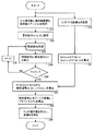
図2は、図1の距離測定装置において、以上に述べた測定原理を実現するための動作を示すフロー図である。 FIG. 2 is a flowchart showing an operation for realizing the measurement principle described above in the distance measuring apparatus of FIG.
図2を参照して、まず計測に先立って、図1の周波数制御部14において、周波数条件が設定される。詳細には、送信部20から放出される電磁波の中心周波数f0、送信周波数範囲fW、掃引する周波数ステップΔfが設定される(ステップS01)。
Referring to FIG. 2 , first, prior to measurement, frequency conditions are set in
周波数条件が設定されると、周波数制御部14は、掃引開始時の送信周波数fとして、f=f0−fW/2を設定する。周波数制御部14は、発信部12のVCOの発振周波数を送信周波数fに制御するための制御信号を出力する(ステップS02)。
When the frequency condition is set, the
発信部12は、周波数制御部14からの制御信号に応じて、自己の発振周波数を送信周波数fに調整し、送信周波数fの信号を出力する(ステップS03)。送信部20は、出力信号と同一周波数fの電磁波を測定対象物Mkに対して放出する。
The
次に、検出部30は、送信周波数fの進行波Dが測定対象物で反射されたときの反射波Rを検出する。このとき、検出部30では、方向性結合器32を介して送信部20の受信信号から反射波Rが検出されると、反射波Rが送信信号により同期検波されて直流成分が抽出されることにより、反射波Rの同相成分I(f),直交成分Q(f)が検出される(ステップS04)。
Next, the
ステップS03およびS04に示す検出動作は、さらに、送信周波数fを周波数ステップΔfだけ増加させて行なわれる(ステップS06)。以上に示す一連の動作は、最終的に送信周波数fが掃引終了時の周波数f0+fW/2に至るまで繰り返される(ステップS05)。 The detection operation shown in steps S03 and S04 is further performed by increasing transmission frequency f by frequency step Δf (step S06). The series of operations described above is repeated until the transmission frequency f finally reaches the frequency f 0 + f W / 2 at the end of the sweep (step S05).
ステップS05において、所定の周波数帯域幅fWでの反射波Rの同相成分I(f),直交成分Q(f)の検出が終了すると、信号処理部40内の解析信号生成部42において、同相成分I(f),直交成分Q(f)から解析信号p(f)が算出される(ステップS07)。
In step S05, when the detection of the in-phase component I (f) and the quadrature component Q (f) of the reflected wave R in the predetermined frequency bandwidth f W is completed, the analysis
このとき、解析信号生成部42では、ステップS10に示すように、測定対象物Mkの位置および移動速度に基づいて所定の距離d0が設定されると、距離d0に応じた周期性を有する信号I0(f),Q0(f)が式(11),(12)を用いて算出される(ステップS11)。そして、ステップS07において、同相成分I(f),直交成分Q(f)と信号I0(f),Q0(f)とがミキシングされ、発生する2つの側帯波のうちの一方(たとえば上側帯波USB)を用いて解析信号p(f)が生成される。
At this time, the analysis
ステップS07にて得られた解析信号p(f)は、フーリエ変換部44においてフーリエ変換される。これにより、プロファイルP(x)が導出される(ステップS08)。
The analysis signal p (f) obtained in step S07 is subjected to Fourier transform in the
最後に、プロファイルP(x)の極大値を抽出することにより、測定対象物Mkの距離dkを求めることができる(ステップS09)。 Finally, by extracting the maximum value of the profile P (x), the distance d k of the measurement object M k can be obtained (step S09).
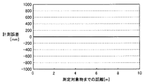
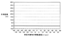
図3は、図1の距離測定装置において、プロファイルP(x)から求められる測定対象物Mkの距離dk(計測値)と実際の測定対象物までの距離との関係を示す図である。なお、同図の関係は、f0=24.0375GHz,fW=75MHz,γk=0.1,φk=πの条件下において、測定対象物Mkの距離dkを0m≦dk≦10mの範囲で変化させたときに得られたものである。 FIG. 3 is a diagram illustrating a relationship between the distance d k (measured value) of the measurement object M k obtained from the profile P (x) and the distance to the actual measurement object in the distance measurement device of FIG. . In addition, the relationship of the figure shows that the distance d k of the measuring object M k is set to 0 m ≦ d k under the conditions of f 0 = 24.0375 GHz, f W = 75 MHz, γ k = 0.1, and φ k = π. It was obtained when changing in the range of ≦ 10 m.
図3に示すように、プロファイルP(x)から得られる測定対象物の距離dkと実際の測定対象物までの距離とは、0m≦dk≦10mの全範囲において、1対1の関係が得られている。これにより、図12に示される従来計測不可能であった距離が2m以下の領域においても計測することができ、特にd=0mからの測距が可能となる。 As shown in FIG. 3 , the distance d k of the measurement object obtained from the profile P (x) and the distance to the actual measurement object have a one-to-one relationship in the entire range of 0 m ≦ d k ≦ 10 m. Is obtained. As a result, it is possible to measure even in a region where the distance that has been impossible in the conventional measurement shown in FIG.
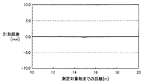
図4は、測定対象物Mkまでの距離dkが遠距離レベル(10m≦dk≦20m)のときの計測値と実際の測定対象物までの距離との関係を示す図である。 4, the distance d k to the object of measurement M k is a diagram showing the relationship between the distance to the measured value and the actual measuring object when the long distance level (10m ≦ d k ≦ 20m) .
図4から明らかなように、測定対象物Mkの距離dkには、図13で示される誤差が生じていない。したがって、中距離以上に位置する測定対象物Mkに対しても、計測誤差を低減することができる。 As apparent from FIG. 4, the error shown in FIG. 13 does not occur in the distance d k of the measurement object M k . Therefore, the measurement error can be reduced even for the measurement object M k located at a medium distance or more.
次に、図1の距離測定装置における移動する測定対象物Mkまでの距離dkの測定動作について説明する。 Next, the measuring operation of the distance d k to the moving measuring object M k in the distance measuring device of FIG. 1 will be described.
図5は、図1に示す距離測定装置における測定動作を説明するためのフロー図である。図5を参照して、まず計測に先立って、図1の周波数制御部14において、周波数条件が設定される。詳細には、送信部20から放出される電磁波の中心周波数f0、送信周波数範囲fW、掃引する周波数ステップΔfが設定される(ステップS20)。以下においては、送信周波数fを、周波数ステップΔfごとに増加(上昇掃引に相当)、または周波数ステップΔfごとに減少(下降掃引に相当)することによって、第1および第2の位置情報がそれぞれ検出される。
FIG. 5 is a flowchart for explaining the measuring operation in the distance measuring apparatus shown in FIG. Referring to FIG. 5 , first, prior to measurement, frequency conditions are set in
まず、上昇掃引においては、周波数条件が設定されると、周波数制御部14は、掃引開始時の送信周波数fとして、f=f0−fW/2を設定する。周波数制御部14は、発信部12のVCOの発振周波数を送信周波数fに制御するための制御信号を出力する(ステップS21)。
First, in the upward sweep, when the frequency condition is set, the
発信部12は、周波数制御部14からの制御信号に応じて、自己の発振周波数を送信周波数fに調整し、送信周波数fの信号を出力する(ステップS22)。送信部20は、出力信号と同一周波数fの電磁波を測定対象物Mkに対して放出する。
The
次に、検出部30は、送信周波数fの進行波Dが測定対象物Mkで反射された反射波Rを検出する。そして、検出部30は、反射波Rを送信信号の同相信号と直交信号とにより同期検波して、反射波Rの同相成分I(f),直交成分Q(f)を検出する(ステップS23)。
Next, the
ステップS22およびS23に示す検出動作は、送信周波数fを周波数ステップΔfだけ増加させて行なわれる(ステップS24)。以上に示す一連の動作は、最終的に送信周波数fが掃引終了時の周波数f0+fW/2に至るまで繰り返される(ステップS25)。 The detection operation shown in steps S22 and S23 is performed by increasing the transmission frequency f by the frequency step Δf (step S24). The series of operations described above is repeated until the transmission frequency f finally reaches the frequency f 0 + f W / 2 at the end of the sweep (step S25).
ステップS25において、所定の周波数範囲fWでの同相成分I(f)および直交成分Q(f)の検出が終了すると、信号処理部40内の解析信号生成部42において、同相成分I(f),直交成分Q(f)と所定の距離d0に応じた周期性の信号I0(f),Q0(f)とがミキシングされ、そのとき生じる上側帯波USBから解析信号p(f)が算出される(ステップS26)。
When the detection of the in-phase component I (f) and the quadrature component Q (f) in the predetermined frequency range f W is completed in step S25, the analysis
さらに、得られた解析信号p(f)は、フーリエ変換部44においてフーリエ変換される。これにより、プロファイルP(x)が導出される(ステップS27)。
Further, the obtained analysis signal p (f) is subjected to Fourier transform in the
最後に、プロファイルP(x)の極大値を抽出し、極大値を与える位置xから所定の距離d0を差し引くことにより、測定対象物Mkの距離dkを求めることができる(ステップS28)。検出された距離dkは、第1の位置情報としてフーリエ変換部44に格納される。
Finally, the maximum value of the profile P (x) is extracted, and the distance d k of the measurement object M k can be obtained by subtracting the predetermined distance d 0 from the position x that gives the maximum value (step S28). . The detected distance d k is stored in the
次に、下降掃引においては、周波数条件が設定されると、周波数制御部14は、掃引開始時の送信周波数fとして、f=f0+fW/2を設定する。周波数制御部14は、発信部12のVCOの発振周波数を送信周波数fに制御するための制御信号を出力する(ステップS31)。
Next, in the downward sweep, when the frequency condition is set, the
発信部12は、周波数制御部14からの制御信号に応じて、自己の発振周波数を送信周波数fに調整し、送信周波数fの信号を出力する。送信部20は、出力信号と同一周波数fの電磁波を測定対象物Mkに対して放出する(ステップS32)。
The
次に、検出部30は、送信周波数fの進行波Dが測定対象物Mkで反射された反射波Rを検出する。そして、ステップS23と同様の手順に従って、反射波Rの同相成分I(f),直交成分Q(f)がそれぞれ検出される(ステップS33)。
Next, the
ステップS32およびS33に示す検出動作は、送信周波数fを周波数ステップΔfだけ減少させて行なわれる(ステップS34)。以上に示す一連の動作は、最終的に送信周波数fが掃引終了時の周波数f0−fW/2に至るまで繰り返される(ステップS35)。 The detection operation shown in steps S32 and S33 is performed by reducing the transmission frequency f by the frequency step Δf (step S34). The series of operations described above is repeated until the transmission frequency f finally reaches the frequency f 0 -f W / 2 at the end of the sweep (step S35).
ステップS34において、所定の周波数範囲fWでの同相成分I(f),直交成分Q(f)の検出が終了すると、信号処理部40内の解析信号生成部42において、同相成分I(f),直交成分Q(f)と、距離d0に応じた周期性の信号I0(f),Q0(f)とがミキシングされ、そのときの上側帯波USBから解析信号p(f)が算出される(ステップS36)。
When the detection of the in-phase component I (f) and the quadrature component Q (f) in the predetermined frequency range f W is completed in step S34, the analysis
得られた解析信号p(f)は、フーリエ変換部44においてフーリエ変換される。これにより、プロファイルP(x)が導出される(ステップS37)。
The obtained analysis signal p (f) is subjected to Fourier transform in the
最後に、プロファイルP(x)の極大値を抽出することにより、測定対象物Mkの距離dkを求めることができる(ステップS38)。検出された距離dkは、第2の位置情報としてフーリエ変換部44に格納される。
Finally, by extracting the maximum value of the profile P (x), the distance d k of the measurement object M k can be obtained (step S38). The detected distance d k is stored in the
フーリエ変換部44は、ステップS28,S38において、第1および第2の位置情報が送られると、これら2つの位置情報を平均化する(ステップS39)。得られた結果は、測定対象物Mkの真の位置情報として取得される(ステップS40)。
When the first and second position information is sent in steps S28 and S38, the
図6は、図5の補正処理から得られる距離(計測値)と測定対象物Mkの移動速度との関係を示す図である。 FIG. 6 is a diagram showing the relationship between the distance (measured value) obtained from the correction process of FIG. 5 and the moving speed of the measuring object Mk .
図6を参照して、上昇掃引時の計測結果である第1の位置情報と、下降掃引時の計測結果である第2の位置情報とを平均化することにより、計測誤差は、測定対象物Mkの移動速度の広い範囲において、略0mに保持されている。 Referring to FIG. 6 , by averaging the first position information that is the measurement result at the time of the upward sweep and the second position information that is the measurement result at the time of the downward sweep, the measurement error is determined as the measurement object. It is maintained at approximately 0 m in a wide range of the moving speed of Mk .
しかしながら、図6において、移動速度が40m/sを超えると、約5.0mの計測誤差が生じてしまう。この計測誤差は、送信周波数fの分割数Nによるサンプリングのためのエリアジングの影響を受けることに起因する。そして、送信周波数fの分割数Nをさらに増加すれば、図7に示すように、高速時における計測誤差を解消することができる。 However, in FIG. 6 , when the moving speed exceeds 40 m / s, a measurement error of about 5.0 m occurs. This measurement error is caused by being affected by aliasing for sampling by the division number N of the transmission frequency f. Then, if further increases the number of divisions N of transmission frequency f, as shown in FIG. 7, it is possible to eliminate the measurement error at high speeds.
以上のように、この発明による距離測定装置によれば、反射波を同期検波して同相成分と直交成分とを検出し、これを所定の距離に応じた周波数だけシフトさせたときの側帯波の一方を解析信号として利用することにより、近距離から遠距離まで精度良く計測することができる。また、測定対象物が高速移動しているときにおいても、送信周波数を上昇掃引および下降掃引して得られる計測結果に補正処理を施すことにより、掃引時間に依存せず、精度良く測距することができる。 As described above, according to the distance measuring apparatus of the present invention, the reflected wave is synchronously detected to detect the in-phase component and the quadrature component, and when the sideband wave is shifted by a frequency corresponding to a predetermined distance, By using one as an analysis signal, it is possible to accurately measure from a short distance to a long distance. In addition, even when the measurement object is moving at high speed, it is possible to accurately measure the distance without depending on the sweep time by applying correction processing to the measurement result obtained by sweeping the transmission frequency up and down. Can do.
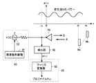
なお、本実施の形態では、反射波Rの検出を方向性結合器32により行なう構成としたが、図8に示すように、受信専用に設けたアンテナ202により検出する構成としても良い。この場合、アンテナ202の受信した信号は直接乗算器24,26の一方入力にそれぞれ入力される。
In the present embodiment, the reflected wave R is detected by the
また、本実施の形態では、この発明における反射波Rの同相成分I(f)および直交成分Q(f)の検出を、アナログ乗算器34,35で反射波Rを同期検波する構成としたが、送信信号の送信周波数fが高く、アナログ乗算器が使用できない場合は、図9で示すように、図1の検出部30における乗算器34,35をダイオードからなる加算器38,39で構成し、反射波Rを包絡線検波することによって検出する構成とすれば良い。なお、この場合、検波信号は、送信信号の直流成分をも含むことから、この直流成分を除去するための手段が別途必要となる。
Further, in the present embodiment, the detection of the in-phase component I of the reflected wave R (f) and the quadrature component Q (f) in the present invention was configured to synchronous detection of reflected wave R by
今回開示された実施の形態はすべての点で例示であって制限的なものではないと考えられるべきである。本発明の範囲は上記した説明ではなく、特許請求の範囲によって示され、特許請求の範囲と均等の意味および範囲内でのすべての変更が含まれることが意図される。 The embodiment disclosed this time should be considered as illustrative in all points and not restrictive. The scope of the present invention is defined by the terms of the claims, rather than the description above, and is intended to include any modifications within the scope and meaning equivalent to the terms of the claims.
10,60 発信源、12,62 発信部、14,64 周波数制御部、20,70 送信部、30,30A,32 方向性結合器、34,35 乗算器、36,37 LPF,38 π/2移相器、80 検出部、40,90 信号処理部、42 解析信号生成部、44,92 フーリエ変換部、M1〜Mn 測定対象物。 10, 60 transmission source, 12, 62 transmission unit, 14, 64 frequency control unit, 20, 70 transmission unit, 30, 30A, 32 directional coupler, 34, 35 multiplier, 36, 37 LPF, 38 π / 2 Phase shifter, 80 detection unit, 40, 90 signal processing unit, 42 analysis signal generation unit, 44, 92 Fourier transform unit, M 1 to M n measurement objects.
Claims (18)
周波数が可変である送信信号を出力する発信源と、
前記送信信号と同一周波数の電磁波を発生し、前記測定対象物に対して放射する送信部と、
前記電磁波の反射波を検出する検出部と、
検出された前記反射波と前記送信周波数との関係を演算処理することによって前記測定対象物までの距離を算出する信号処理部とを備え、
前記検出部は、
検出された前記反射波を前記送信信号により同期検波して前記反射波の位相変化成分を抽出する検波手段を含み、
前記信号処理部は、
抽出された前記位相変化成分の変動周波数を、所定の距離に応じた周波数だけ変化させる周波数変換手段と、
前記周波数変換手段により得られる上側帯波および下側帯波のうちの一方を解析信号とする解析信号生成手段と、
前記解析信号をフーリエ変換してプロファイルを算出し、前記プロファイルの極大値と前記所定の距離とに基づいて前記測定対象物までの距離を求めるフーリエ変換手段とを含む、距離測定装置。 A distance measuring device for measuring a distance to a measurement object,
A transmission source that outputs a transmission signal having a variable frequency ;
A transmitter that generates an electromagnetic wave having the same frequency as the transmission signal and radiates the electromagnetic wave to the measurement object;
A detection unit for detecting a reflected wave of the electromagnetic wave;
A signal processing unit that calculates a distance to the measurement object by calculating a relationship between the detected reflected wave and the transmission frequency;
The detector is
Including detection means for synchronously detecting the detected reflected wave with the transmission signal and extracting a phase change component of the reflected wave;
The signal processing unit
A frequency conversion unit that changes the fluctuation frequency of the extracted phase change component by a frequency according to a predetermined distance;
An analysis signal generating means having one of the upper sideband and the lower sideband obtained by the frequency conversion means as an analysis signal;
A distance measuring device comprising: Fourier transform means for calculating a profile by Fourier transforming the analysis signal, and obtaining a distance to the measurement object based on a maximum value of the profile and the predetermined distance.
所定の送信周波数を所定の帯域幅で所定のステップで上昇させて掃引する上昇掃引手段と、
前記所定の送信周波数を前記所定の帯域幅で所定のステップで下降させて掃引する下降掃引手段とを含み、
前記信号処理部は、
前記上昇掃引手段に応じて前記フーリエ変換手段にて得られる前記測定対象物までの距離を第1の位置情報とし、前記下降掃引手段に応じて前記フーリエ変換手段にて得られる前記測定対象物までの距離を第2の位置情報として保持する手段と、
保持された前記第1および第2の位置情報を平均化して真の前記測定対象物までの距離を導出する補正手段とをさらに含む、請求項1に記載の距離測定装置。 The source is
And upward sweeping means for sweeping upward a predetermined step in bandwidth Jo Tokoro the transmission frequency of Jo Tokoro,
Down sweep means for sweeping down the predetermined transmission frequency in a predetermined step at a predetermined bandwidth;
The signal processing unit
The distance to the measurement object obtained by the Fourier transform means according to the ascending sweep means is the first position information, and the measurement object obtained by the Fourier transform means according to the descending sweep means Means for holding the distance as second position information;
Retained the first and second position information by averaging further comprises a correction means for deriving the distance to the true of the measurement object, the distance measuring apparatus according to claim 1.
周波数が可変である信号を出力するステップと、
前記信号と同一周波数の電磁波を発生し、前記測定対象物に対して放射するステップと、
前記電磁波の反射波を検出するステップと、
検出した前記反射波と前記送信周波数との関係を演算処理することによって前記測定対象物までの距離を算出するステップとを備え、
前記反射波を検出するステップは、
検出された前記反射波を前記送信信号により同期検波して前記反射波の位相変化成分を抽出するステップを含み、
前記測定対象物までの距離を算出するステップは、
抽出された前記位相変化成分の変動周波数を、所定の距離に応じた周波数だけ変化させるステップと、
前記周波数を変化させて得られる上側帯波および下側帯波のうちの一方を解析信号とするステップと、
前記解析信号をフーリエ変換してプロファイルを算出し、前記プロファイルの極大値と前記所定の距離とに基づいて前記測定対象物までの距離を求めるステップとを含む、距離測定方法。 A distance measurement method for measuring a distance to a measurement object,
Outputting a signal having a variable frequency ;
Generating an electromagnetic wave having the same frequency as the signal and radiating the electromagnetic wave to the measurement object;
Detecting a reflected wave of the electromagnetic wave;
Calculating the distance to the measurement object by calculating the relationship between the detected reflected wave and the transmission frequency, and
Detecting the reflected wave comprises:
Including synchronously detecting the detected reflected wave with the transmission signal and extracting a phase change component of the reflected wave;
Calculating the distance to the measurement object,
Changing the extracted variation frequency of the phase change component by a frequency corresponding to a predetermined distance;
One of an upper sideband and a lower sideband obtained by changing the frequency as an analysis signal;
A distance measurement method comprising: calculating a profile by performing Fourier transform on the analysis signal, and obtaining a distance to the measurement object based on a maximum value of the profile and the predetermined distance.
所定の送信周波数を所定の帯域幅で所定のステップで上昇させて掃引するステップと、
前記所定の送信周波数を前記所定の帯域幅で所定のステップで下降させて掃引するステップとを含み、
前記測定対象物までの距離を算出するステップは、
前記上昇掃引したときに前記フーリエ変換にて得られる前記測定対象物までの距離を第1の位置情報とし、前記下降掃引したときに前記フーリエ変換にて得られる前記測定対象物までの距離を第2の位置情報として保持するステップと、
保持された前記第1および第2の位置情報を平均化して真の前記測定対象物までの距離を導出するステップとをさらに含む、請求項7に記載の距離測定方法。 Outputting a signal having a variable frequency ;
A step of sweeping upward a predetermined step in bandwidth up a transmission frequency of Jo Tokoro Tokoro,
Sweeping down the predetermined transmission frequency in a predetermined step at a predetermined bandwidth; and
Calculating the distance to the measurement object,
The distance to the measurement object obtained by the Fourier transform when the upward sweep is performed is the first position information, and the distance to the measurement object obtained by the Fourier transform when the downward sweep is performed is the first position information. 2 as position information of 2;
The distance measurement method according to claim 7, further comprising: averaging the held first and second position information to derive a true distance to the measurement object.
コンピュータに、
周波数が可変である信号を出力するステップと、
前記信号と同一周波数の電磁波を発生し、前記測定対象物に対して放射するステップと、
前記電磁波の反射波を検出するステップと、
検出した前記反射波と前記送信周波数との関係を演算処理することによって前記測定対象物までの距離を算出するステップとを実行させ、
前記反射波を検出するステップは、
検出された前記反射波を前記送信信号により同期検波して前記反射波の位相変化成分を抽出するステップを含み、
前記測定対象物までの距離を算出するステップは、
抽出された前記位相変化成分の変動周波数を、所定の距離に応じた周波数だけ変化させるステップと、
前記周波数を変化させて得られる上側帯波および下側帯波のうちの一方を解析信号とするステップと、
前記解析信号をフーリエ変換してプロファイルを算出し、前記プロファイルの極大値と前記所定の距離とに基づいて前記測定対象物までの距離を求めるステップとを含む、距離測定プログラム。 A distance measurement program for measuring the distance to a measurement object,
On the computer,
Outputting a signal having a variable frequency ;
Generating an electromagnetic wave having the same frequency as the signal and radiating the electromagnetic wave to the measurement object;
Detecting a reflected wave of the electromagnetic wave;
Calculating the distance to the measurement object by calculating the relationship between the detected reflected wave and the transmission frequency,
Detecting the reflected wave comprises:
Including synchronously detecting the detected reflected wave with the transmission signal and extracting a phase change component of the reflected wave;
Calculating the distance to the measurement object,
Changing the extracted variation frequency of the phase change component by a frequency corresponding to a predetermined distance;
One of an upper sideband and a lower sideband obtained by changing the frequency as an analysis signal;
A distance measurement program comprising: calculating a profile by performing Fourier transform on the analysis signal, and obtaining a distance to the measurement object based on a maximum value of the profile and the predetermined distance.
所定の送信周波数を所定の帯域幅で所定のステップで上昇させて掃引するステップと、
前記所定の送信周波数を前記所定の帯域幅で所定のステップで下降させて掃引するステップとを含み、
前記測定対象物までの距離を算出するステップは、
前記上昇掃引したときに前記フーリエ変換にて得られる前記測定対象物までの距離を第1の位置情報とし、前記下降掃引したときに前記フーリエ変換にて得られる前記測定対象物までの距離を第2の位置情報として保持するステップと、
保持された前記第1および第2の位置情報を平均化して真の前記測定対象物までの距離を導出するステップとをさらに含む、請求項13に記載の距離測定プログラム。 Outputting a signal having a variable frequency ;
A step of sweeping upward a predetermined step in bandwidth up a transmission frequency of Jo Tokoro Tokoro,
Sweeping down the predetermined transmission frequency in a predetermined step at a predetermined bandwidth; and
Calculating the distance to the measurement object,
The distance to the measurement object obtained by the Fourier transform when the upward sweep is performed is the first position information, and the distance to the measurement object obtained by the Fourier transform when the downward sweep is performed is the first position information. 2 as position information of 2;
The distance measurement program according to claim 13, further comprising: averaging the held first and second position information to derive a true distance to the measurement object.
Priority Applications (9)
| Application Number | Priority Date | Filing Date | Title |
|---|---|---|---|
| JP2005206798A JP3784823B1 (en) | 2005-07-15 | 2005-07-15 | Distance measuring device, distance measuring method, and distance measuring program |
| KR1020060057338A KR100779811B1 (en) | 2005-07-15 | 2006-06-26 | Distance Measuring Device, Distance Measuring Method and Recording Medium for Distance Measuring Program |
| CA2551321A CA2551321C (en) | 2005-07-15 | 2006-06-27 | Distance measuring device, distance measuring method and distance measuring program |
| TW095124767A TWI300851B (en) | 2005-07-15 | 2006-07-07 | Distance measuring device, distance measuring method and signal processing device |
| CN2006101015512A CN1896766B (en) | 2005-07-15 | 2006-07-12 | Distance measuring device and distance measuring method |
| US11/486,086 US7479921B2 (en) | 2005-07-15 | 2006-07-14 | Distance measuring device, distance measuring method and distance measuring program |
| EP06014738A EP1744176B1 (en) | 2005-07-15 | 2006-07-14 | Distance measuring device, distance measuring method and distance measuring program |
| DE602006000743T DE602006000743T2 (en) | 2005-07-15 | 2006-07-14 | Distance measuring device, distance measuring method and distance measuring program |
| HK07107327.2A HK1099813A1 (en) | 2005-07-15 | 2007-07-09 | Distance measuring device and distance measuring method |
Applications Claiming Priority (1)
| Application Number | Priority Date | Filing Date | Title |
|---|---|---|---|
| JP2005206798A JP3784823B1 (en) | 2005-07-15 | 2005-07-15 | Distance measuring device, distance measuring method, and distance measuring program |
Publications (2)
| Publication Number | Publication Date |
|---|---|
| JP3784823B1 true JP3784823B1 (en) | 2006-06-14 |
| JP2007024671A JP2007024671A (en) | 2007-02-01 |
Family
ID=36635805
Family Applications (1)
| Application Number | Title | Priority Date | Filing Date |
|---|---|---|---|
| JP2005206798A Active JP3784823B1 (en) | 2005-07-15 | 2005-07-15 | Distance measuring device, distance measuring method, and distance measuring program |
Country Status (9)
| Country | Link |
|---|---|
| US (1) | US7479921B2 (en) |
| EP (1) | EP1744176B1 (en) |
| JP (1) | JP3784823B1 (en) |
| KR (1) | KR100779811B1 (en) |
| CN (1) | CN1896766B (en) |
| CA (1) | CA2551321C (en) |
| DE (1) | DE602006000743T2 (en) |
| HK (1) | HK1099813A1 (en) |
| TW (1) | TWI300851B (en) |
Cited By (2)
| Publication number | Priority date | Publication date | Assignee | Title |
|---|---|---|---|---|
| WO2007029519A1 (en) * | 2005-09-02 | 2007-03-15 | Saika Technological Institute Foundation | Distance measuring device and distance measuring method |
| JP2008066867A (en) * | 2006-09-05 | 2008-03-21 | Sony Ericsson Mobilecommunications Japan Inc | Power amplifier control unit, and mobile communication terminal unit |
Families Citing this family (32)
| Publication number | Priority date | Publication date | Assignee | Title |
|---|---|---|---|---|
| US7659847B2 (en) * | 2006-06-29 | 2010-02-09 | Stolar, Inc. | Radar mining guidance control system |
| US7656342B2 (en) * | 2006-10-23 | 2010-02-02 | Stolar, Inc. | Double-sideband suppressed-carrier radar to null near-field reflections from a first interface between media layers |
| US7548181B1 (en) * | 2006-06-29 | 2009-06-16 | Stolar, Inc. | Earth-penetrating radar with inherent near-field rejection |
| DE102007042954A1 (en) * | 2007-08-30 | 2009-03-05 | Balluff Gmbh | Microwave proximity sensor and method for determining the distance between a probe and a target |
| US7808426B1 (en) * | 2008-05-05 | 2010-10-05 | The United States Of America As Represented By The Secretary Of The Navy | Remote sensing of wave heights using a broadband radar arrangement |
| US7830302B1 (en) * | 2008-05-05 | 2010-11-09 | The United States Of America As Represented By The Secretary Of The Navy | Remote sensing of wave heights using a narrowband radar arrangement |
| JP5547197B2 (en) * | 2008-09-18 | 2014-07-09 | ケーシーアイ ライセンシング インコーポレイテッド | Multilayer dressing, system, and method for applying reduced pressure to a tissue site |
| DE102009024883A1 (en) * | 2009-06-09 | 2010-12-16 | Metek Metereologische Meßtechnik GmbH | Method and device for measuring a change in distance |
| JPWO2011142211A1 (en) * | 2010-05-11 | 2013-07-22 | アルプス電気株式会社 | Communication sensor device |
| US8400346B2 (en) * | 2010-06-25 | 2013-03-19 | Glass Wind, Llc | Method and apparatus for locating a golf ball with doppler radar |
| US8605150B1 (en) * | 2010-10-29 | 2013-12-10 | Lockheed Martin Corporation | Single image DC-removal method for increasing the precision of two-dimensional fourier transform profilometry |
| PL2450823T3 (en) | 2010-11-04 | 2013-11-29 | Keba Ag | detecting a foreign body in the vicinity of a means of input used for authentification |
| CN102155905B (en) * | 2011-03-28 | 2012-10-24 | 中国矿业大学 | Device and method for nondestructive measurement of anchor rod length |
| US9316731B2 (en) * | 2011-08-04 | 2016-04-19 | Lattice Semiconductor Corporation | Low-cost tracking system |
| HUE059883T2 (en) * | 2012-01-25 | 2023-01-28 | Grieshaber Vega Kg | Envelope calculation by means of phase shifting |
| US9031523B2 (en) * | 2012-06-26 | 2015-05-12 | Htc Corporation | Systems and methods for determining antenna impedance |
| CN102749618B (en) * | 2012-07-19 | 2014-01-29 | 浙江大学 | Method and system for measuring motion trajectory of object by difference and cross-multiplication module |
| JP6166032B2 (en) | 2012-11-06 | 2017-07-19 | 浜松ホトニクス株式会社 | Semiconductor device inspection apparatus and semiconductor device inspection method |
| EP2992356B1 (en) | 2013-04-29 | 2021-08-11 | Greina Technologies Inc. | Personal radar |
| US10656257B2 (en) | 2013-04-29 | 2020-05-19 | Greina Technologies, Inc. | Personal radar |
| TWI464441B (en) * | 2013-08-28 | 2014-12-11 | U & U Engineering Inc | Microwave sensor with range gate functions |
| CN107250839B (en) * | 2015-02-23 | 2020-04-21 | 三菱电机株式会社 | Moving distance measuring device |
| TWI580987B (en) * | 2016-04-29 | 2017-05-01 | Metal Ind Res & Dev Ct | A positioning algorithm for calculating the positioning distance |
| CN108072872A (en) * | 2016-11-17 | 2018-05-25 | 富士通株式会社 | Information extracting device, article detection apparatus |
| JP6880850B2 (en) * | 2017-03-13 | 2021-06-02 | 富士通株式会社 | Distance measuring device, water level measurement system and distance measuring method |
| US10447466B2 (en) * | 2018-01-18 | 2019-10-15 | Mediatek Inc. | Transceiver and clock generation module |
| KR102077000B1 (en) | 2018-01-29 | 2020-04-07 | 주식회사 만도 | Apparatus and Method for compensating refection loss of antenna for Radar, and Radar Apparatus using the same |
| KR102207959B1 (en) * | 2018-03-30 | 2021-01-25 | 박영준 | Unit for measuring level using electromagnetic wave, apparatus for manufacturing asphalt concrete including the same, and method of manufacturing asphalt concrete |
| JP7061364B2 (en) * | 2018-06-11 | 2022-04-28 | 国立大学法人東京農工大学 | Distance measuring device and distance measuring method |
| CN109031315B (en) * | 2018-06-26 | 2022-07-01 | 北京小米移动软件有限公司 | Distance measuring method, device, equipment and storage medium |
| CN114578363B (en) * | 2022-03-04 | 2023-10-13 | 苏州优达斯汽车科技有限公司 | Ultrasonic detection system and method |
| CN117607848B (en) * | 2024-01-24 | 2024-04-09 | 烟台初心航空科技有限公司 | FDR-based radar positioning and ranging method |
Family Cites Families (15)
| Publication number | Priority date | Publication date | Assignee | Title |
|---|---|---|---|---|
| US3113309A (en) * | 1959-05-04 | 1963-12-03 | Avco Corp | Method and apparatus for measuring altitude |
| DE2748124C2 (en) * | 1977-10-27 | 1983-01-13 | Philips Patentverwaltung Gmbh, 2000 Hamburg | Arrangement for distance measurement according to the FM-CW radar principle |
| CA2038818A1 (en) | 1990-03-30 | 1991-10-01 | Akio Nagamune | Distance measuring method and apparatus therefor |
| US5361070B1 (en) | 1993-04-12 | 2000-05-16 | Univ California | Ultra-wideband radar motion sensor |
| DE4334079C2 (en) | 1993-10-06 | 1997-02-13 | Daimler Benz Aerospace Ag | Highly accurate radar range finder |
| JP3006904U (en) | 1994-07-19 | 1995-01-31 | 古野電気株式会社 | Distance measuring device |
| TW251353B (en) | 1994-12-10 | 1995-07-11 | Kono Denki Kk | Distance measuring device |
| US6133993A (en) * | 1998-01-26 | 2000-10-17 | Trw Inc. | Length and velocity measurement apparatus |
| JPH11316271A (en) | 1998-05-01 | 1999-11-16 | Nissan Motor Co Ltd | Radar device |
| US6492933B1 (en) | 1999-09-02 | 2002-12-10 | Mcewan Technologies, Llc | SSB pulse Doppler sensor and active reflector system |
| JP3461498B2 (en) * | 2001-03-01 | 2003-10-27 | 徹志 上保 | Distance measuring device, distance measuring equipment and distance measuring method |
| WO2003104841A1 (en) * | 2002-06-07 | 2003-12-18 | 株式会社島精機製作所 | Distance measurement method and device |
| JP2004085473A (en) | 2002-08-28 | 2004-03-18 | Mitsubishi Electric Corp | Distance measuring system |
| JP3782409B2 (en) | 2002-08-30 | 2006-06-07 | 積水樹脂株式会社 | Moving object distance detection system |
| JP4328555B2 (en) | 2003-04-21 | 2009-09-09 | Necアクセステクニカ株式会社 | Distance measuring method, distance measuring apparatus to which the distance measuring method is applied, and distance measuring equipment to which the distance measuring apparatus is applied |
-
2005
- 2005-07-15 JP JP2005206798A patent/JP3784823B1/en active Active
-
2006
- 2006-06-26 KR KR1020060057338A patent/KR100779811B1/en active IP Right Grant
- 2006-06-27 CA CA2551321A patent/CA2551321C/en active Active
- 2006-07-07 TW TW095124767A patent/TWI300851B/en active
- 2006-07-12 CN CN2006101015512A patent/CN1896766B/en active Active
- 2006-07-14 DE DE602006000743T patent/DE602006000743T2/en active Active
- 2006-07-14 EP EP06014738A patent/EP1744176B1/en active Active
- 2006-07-14 US US11/486,086 patent/US7479921B2/en active Active
-
2007
- 2007-07-09 HK HK07107327.2A patent/HK1099813A1/en unknown
Cited By (2)
| Publication number | Priority date | Publication date | Assignee | Title |
|---|---|---|---|---|
| WO2007029519A1 (en) * | 2005-09-02 | 2007-03-15 | Saika Technological Institute Foundation | Distance measuring device and distance measuring method |
| JP2008066867A (en) * | 2006-09-05 | 2008-03-21 | Sony Ericsson Mobilecommunications Japan Inc | Power amplifier control unit, and mobile communication terminal unit |
Also Published As
| Publication number | Publication date |
|---|---|
| KR20070009388A (en) | 2007-01-18 |
| TWI300851B (en) | 2008-09-11 |
| HK1099813A1 (en) | 2007-08-24 |
| US7479921B2 (en) | 2009-01-20 |
| CA2551321A1 (en) | 2007-01-15 |
| TW200704952A (en) | 2007-02-01 |
| CA2551321C (en) | 2011-03-29 |
| CN1896766B (en) | 2010-05-12 |
| EP1744176B1 (en) | 2008-03-19 |
| EP1744176A1 (en) | 2007-01-17 |
| JP2007024671A (en) | 2007-02-01 |
| DE602006000743D1 (en) | 2008-04-30 |
| KR100779811B1 (en) | 2007-11-29 |
| US20070013578A1 (en) | 2007-01-18 |
| CN1896766A (en) | 2007-01-17 |
| DE602006000743T2 (en) | 2008-07-10 |
Similar Documents
| Publication | Publication Date | Title |
|---|---|---|
| JP3784823B1 (en) | Distance measuring device, distance measuring method, and distance measuring program | |
| CN106371097B (en) | Radar system | |
| JP4293194B2 (en) | Distance measuring device and distance measuring method | |
| JP4407769B2 (en) | Radar equipment | |
| CN101036068B (en) | Electro-optical method for measuring distance and detecting a non-ideal chirp profile | |
| CN101201400A (en) | Method and device for correcting non-ideal intermediate-frequency signals in an FMCW radar | |
| JP2006220624A (en) | Fmcw radar device | |
| JP2012112861A (en) | Fm-cw radar device and pairing method | |
| US10120072B2 (en) | Method for determining a distance between an FMCW ranging device and a target | |
| JP2001524207A (en) | Sensor device operating method and sensor device | |
| Zhang et al. | Software-defined six-port radar technique for precision range measurements | |
| US10735113B2 (en) | Near-field measurement system and near-field measurement method | |
| US20190025419A1 (en) | Moving object detection system and moving object detection method | |
| JP2008541025A (en) | Method and apparatus for determining the distance to a target object | |
| Chaudhari et al. | Frequency estimator to improve short range accuracy in FMCW radar | |
| JP3768511B2 (en) | Distance measuring device, distance measuring method, and distance measuring program | |
| JP2004301617A (en) | Microwave type level meter | |
| JP3973036B2 (en) | Pulse radar equipment | |
| JP2007127529A (en) | Distance measuring instrument, and method | |
| RU2347235C2 (en) | Method of formation coherent frequency modulated signal for radar stations with periodic fm modulation and device for its realisation | |
| JP4732177B2 (en) | Radar apparatus calibration apparatus and method | |
| Liu et al. | Linearity study of DDS-based W-band FMCW sensor | |
| KR102288866B1 (en) | Method for increasing range resolution using existing radar information | |
| JP2006177979A (en) | Pulse radar device | |
| KR101347000B1 (en) | Method for estimating frequency of a digital input signal |
Legal Events
| Date | Code | Title | Description |
|---|---|---|---|
| TRDD | Decision of grant or rejection written | ||
| A01 | Written decision to grant a patent or to grant a registration (utility model) |
Free format text: JAPANESE INTERMEDIATE CODE: A01 Effective date: 20060228 |
|
| A61 | First payment of annual fees (during grant procedure) |
Free format text: JAPANESE INTERMEDIATE CODE: A61 Effective date: 20060315 |
|
| R150 | Certificate of patent or registration of utility model |
Ref document number: 3784823 Country of ref document: JP Free format text: JAPANESE INTERMEDIATE CODE: R150 Free format text: JAPANESE INTERMEDIATE CODE: R150 |
|
| FPAY | Renewal fee payment (event date is renewal date of database) |
Free format text: PAYMENT UNTIL: 20090324 Year of fee payment: 3 |
|
| FPAY | Renewal fee payment (event date is renewal date of database) |
Free format text: PAYMENT UNTIL: 20100324 Year of fee payment: 4 |
|
| R250 | Receipt of annual fees |
Free format text: JAPANESE INTERMEDIATE CODE: R250 |
|
| FPAY | Renewal fee payment (event date is renewal date of database) |
Free format text: PAYMENT UNTIL: 20110324 Year of fee payment: 5 |
|
| R250 | Receipt of annual fees |
Free format text: JAPANESE INTERMEDIATE CODE: R250 |
|
| FPAY | Renewal fee payment (event date is renewal date of database) |
Free format text: PAYMENT UNTIL: 20110324 Year of fee payment: 5 |
|
| R250 | Receipt of annual fees |
Free format text: JAPANESE INTERMEDIATE CODE: R250 |
|
| FPAY | Renewal fee payment (event date is renewal date of database) |
Free format text: PAYMENT UNTIL: 20120324 Year of fee payment: 6 |
|
| FPAY | Renewal fee payment (event date is renewal date of database) |
Free format text: PAYMENT UNTIL: 20130324 Year of fee payment: 7 |
|
| R250 | Receipt of annual fees |
Free format text: JAPANESE INTERMEDIATE CODE: R250 |
|
| FPAY | Renewal fee payment (event date is renewal date of database) |
Free format text: PAYMENT UNTIL: 20130324 Year of fee payment: 7 |
|
| FPAY | Renewal fee payment (event date is renewal date of database) |
Free format text: PAYMENT UNTIL: 20140324 Year of fee payment: 8 |
|
| R250 | Receipt of annual fees |
Free format text: JAPANESE INTERMEDIATE CODE: R250 |
|
| R250 | Receipt of annual fees |
Free format text: JAPANESE INTERMEDIATE CODE: R250 |
|
| R250 | Receipt of annual fees |
Free format text: JAPANESE INTERMEDIATE CODE: R250 |
|
| R250 | Receipt of annual fees |
Free format text: JAPANESE INTERMEDIATE CODE: R250 |
|
| R250 | Receipt of annual fees |
Free format text: JAPANESE INTERMEDIATE CODE: R250 |
|
| R250 | Receipt of annual fees |
Free format text: JAPANESE INTERMEDIATE CODE: R250 |
|
| R250 | Receipt of annual fees |
Free format text: JAPANESE INTERMEDIATE CODE: R250 |
|
| R250 | Receipt of annual fees |
Free format text: JAPANESE INTERMEDIATE CODE: R250 |
|
| R250 | Receipt of annual fees |
Free format text: JAPANESE INTERMEDIATE CODE: R250 |
|
| R250 | Receipt of annual fees |
Free format text: JAPANESE INTERMEDIATE CODE: R250 |
|
| R250 | Receipt of annual fees |
Free format text: JAPANESE INTERMEDIATE CODE: R250 |