JP3565470B2 - Ground fault protection device and operation method thereof, photovoltaic power generation system having the same, and inverter for photovoltaic power generation system having the same - Google Patents
Ground fault protection device and operation method thereof, photovoltaic power generation system having the same, and inverter for photovoltaic power generation system having the same Download PDFInfo
- Publication number
- JP3565470B2 JP3565470B2 JP15674597A JP15674597A JP3565470B2 JP 3565470 B2 JP3565470 B2 JP 3565470B2 JP 15674597 A JP15674597 A JP 15674597A JP 15674597 A JP15674597 A JP 15674597A JP 3565470 B2 JP3565470 B2 JP 3565470B2
- Authority
- JP
- Japan
- Prior art keywords
- ground fault
- protection device
- power generation
- time period
- signal
- Prior art date
- Legal status (The legal status is an assumption and is not a legal conclusion. Google has not performed a legal analysis and makes no representation as to the accuracy of the status listed.)
- Expired - Fee Related
Links
Images


Classifications
-
- H—ELECTRICITY
- H02—GENERATION; CONVERSION OR DISTRIBUTION OF ELECTRIC POWER
- H02H—EMERGENCY PROTECTIVE CIRCUIT ARRANGEMENTS
- H02H7/00—Emergency protective circuit arrangements specially adapted for specific types of electric machines or apparatus or for sectionalised protection of cable or line systems, and effecting automatic switching in the event of an undesired change from normal working conditions
- H02H7/10—Emergency protective circuit arrangements specially adapted for specific types of electric machines or apparatus or for sectionalised protection of cable or line systems, and effecting automatic switching in the event of an undesired change from normal working conditions for converters; for rectifiers
- H02H7/12—Emergency protective circuit arrangements specially adapted for specific types of electric machines or apparatus or for sectionalised protection of cable or line systems, and effecting automatic switching in the event of an undesired change from normal working conditions for converters; for rectifiers for static converters or rectifiers
- H02H7/122—Emergency protective circuit arrangements specially adapted for specific types of electric machines or apparatus or for sectionalised protection of cable or line systems, and effecting automatic switching in the event of an undesired change from normal working conditions for converters; for rectifiers for static converters or rectifiers for inverters, i.e. dc/ac converters
-
- H—ELECTRICITY
- H02—GENERATION; CONVERSION OR DISTRIBUTION OF ELECTRIC POWER
- H02H—EMERGENCY PROTECTIVE CIRCUIT ARRANGEMENTS
- H02H3/00—Emergency protective circuit arrangements for automatic disconnection directly responsive to an undesired change from normal electric working condition with or without subsequent reconnection ; integrated protection
- H02H3/16—Emergency protective circuit arrangements for automatic disconnection directly responsive to an undesired change from normal electric working condition with or without subsequent reconnection ; integrated protection responsive to fault current to earth, frame or mass
Landscapes
- Engineering & Computer Science (AREA)
- Power Engineering (AREA)
- Protection Of Static Devices (AREA)
- Photovoltaic Devices (AREA)
- Inverter Devices (AREA)
- Emergency Protection Circuit Devices (AREA)
- Supply And Distribution Of Alternating Current (AREA)
- Charge And Discharge Circuits For Batteries Or The Like (AREA)
Description
【0001】
【産業上の利用分野】
本発明は、地絡保護装置並びにその動作方法、これを有した太陽光発電システム及びこれを有した太陽光発電システム用インバータに係る。より詳細には、太陽電池アレイの内部で生じる地絡の検出感度を高く保持した状態で、太陽光発電システムの不必要な停止を防止できる、地絡保護装置並びにその動作方法、これを有した太陽光発電システム及びこれを有した太陽光発電システム用インバータに関する。
【0002】
【従来の技術】
太陽電池アレイは、複数個の太陽電池を直並列接続したものであり、個々の太陽電池に十分太陽光が照射されるように屋外に設置して用いられる。従って、例えば1つの太陽電池において、導電性の物体(例えば、金属体はもとより、動物や人間など)と誤って接触してアース電位との短絡(以後、この現象を地絡と呼称する)が生じると、太陽電池アレイが組み込まれた太陽光発電システムは、安全対策上その動作を一端停止せざるをえない。このようなシステムの停止は、システムが接続されている負荷に対して多大な影響を与える。
【0003】
図2は、上記対策として制御・保護装置を設けた系統連係型の太陽光発電システムの一例を示す構成図である。図2において、21は太陽電池アレイ、22はインバータ、23は制御・保護装置、24は遮断装置、25は電力系統である。
【0004】
図2のシステムでは、太陽電池アレイ21はインバータ22を介して電力系統25に電力を送出する。インバータ22と電力系統25との間には機械的接点を有した遮断装置24が設けられ、システムの故障時には電力系統25と太陽電池アレイ21との間を機械的に分離すると共に、インバータの内部のスイッチング素子が電子的にOFFされる、いわゆるゲートブロック動作が行われる。制御・保護装置23は電力系統25と太陽電池アレイ21の状態を検出し、上記遮断動作を行う。具体的には、システムの故障状態を検出すると、ゲートブロック信号と遮断装置の動作指令信号とを送出し、遮断動作を実行する。システムの故障としては、例えば、電力系統25の異常、太陽電池アレイ21内の地絡異常等が挙げられる。
【0005】
特に、後者の地絡異常に対しては以下に示すような保護動作が一般的に採られていた。
(1)従来技術1(瞬時停止タイプ):地絡異常を検出した時、瞬時に応答し、システムを遮断する方法。
(2)従来技術2(一定時限停止タイプ):地絡異常を検出した時、一定時間が経ってから遮断動作を行う方法。この一定時間としては、約0.5秒以下が一般的である。
【0006】
しかしながら、上記従来技術には次のような課題があった。
【0007】
▲1▼瞬時に遮断動作を行う方法(従来技術1)には、ノイズ等の混入により誤動作しやすいという問題があり、検出感度をあまり高めることはできなかった。誤動作が頻繁に起きると遮断装置24の接点の機械的開閉回数が増加し、遮断装置の寿命を縮めることにつながる。
【0008】
▲2▼遮断までに一定時限をおく方法(従来技術2)には、動作時限が短い場合は誤動作が起きやすくなるので検出感度を高めることが難しく、この時限を長く設定してしまうと保護動作自体が遅くなってしまうので保護の役目を果たさないという問題があった。
【0009】
【発明が解決しようとする課題】
本発明は、太陽電池アレイの内部で生じる地絡の検出感度を高く保持した状態で、太陽光発電システムの不必要な停止を防止できる、地絡保護装置並びにその動作方法、これを有した太陽光発電システム及びこれを有した太陽光発電システム用インバータを提供することを目的とする。
【0010】
【課題を解決するための手段】
本発明に係る地絡保護装置は、太陽電池アレイの内部において地絡が発生したとき、該太陽電池アレイと負荷との間に設けたゲートブロック手段に対してはゲートブロック信号を、該太陽電池アレイと前記負荷との間に設けた機械的な遮断手段に対しては遮断指令信号を、個別に出力し、
かつ、地絡検出手段と時間計測手段とを備え、
さらに、前記地絡検出手段及び前記時間計測手段を用いて、
地絡が所定の第1の時限T1の間継続して発生していることを検出したときにはゲートブロック信号を前記ゲートブロック手段に対して出力し、
その後、前記第1の時限T1より長い第2の時限T2が経過してから、地絡が再び検出されたときには故障と判断して遮断指令信号を前記機械的な遮断手段に対して与え、
地絡が再び検出されなかったときには前記ゲートブロック信号を解除する
ことを特徴としている。
【0011】
時間計測手段を用いることにより、所定の時間及び所定の時間間隔で、太陽電池アレイの内部における地絡発生の有無を地絡検出手段で調べることができるため、太陽電池アレイの定期的な診断が可能となり、誤動作が低減することから長時間の運用においても高い信頼性を有する地絡保護装置がえられる。
【0012】
また上記特徴において、前記地絡保護装置は、前記地絡検出手段及び前記時間計測手段を用いて、地絡が所定の第1の時限T1の間継続して発生していることを検出したときにはゲートブロック信号を前記ゲートブロック手段に対して出力し、その後、前記第1の時限T1より長い第2の時限T2が経過してから、地絡が再び検出されたときには故障と判断して遮断指令信号を前記機械的な遮断手段に対して与え、地絡が再び検出されなかったときには前記ゲートブロック信号を解除することにより、まず比較的短いT1時間地絡が継続したことを検出した時には機械的遮断を伴わないゲートブロック動作のみ行ってインバータを停止し、その後、T2時間が経ってからなお地絡が検出された時に初めて機械的な遮断(電力系統との分離)を行うという制御が可能となる。そのため、地絡検出手段の検出感度を高くしても、誤検知による機械的遮断を減らすことができ、遮断手段の寿命を長くできる。また、インバータ自体の動作は最初の地絡検出時に停止させてあるので、従来技術で時限を長くした場合のように保護動作の目的(安全性の確保)を損ねることもない。
【0013】
上述した地絡検出手段と時間計測手段とを備えた地絡保護装置の動作方法は、地絡が所定の第1の時限T1の間継続して発生していることを検出したときには軽度地絡信号を生成する第1工程と、前記第1工程の後、前記第1の時限T1より長い第2の時限T2が経過してから、再び地絡の有無を検査する第2の工程と、前記第2工程において地絡が再び検出されたときには故障と判断して重度地絡信号を生成し、前記第2工程において地絡が再び検出されなかったときには前記軽度地絡信号を解除する第3の工程と、を有することにより達成される。
【0014】
【発明の実施の形態】
以下では、本発明に係る地絡保護装置並びにその動作方法、これを有した太陽光発電システム及びこれを有した太陽光発電システム用インバータについて具体的に説明する。
【0015】
(実施例1)
図2は、本発明に係る地絡保護装置を、系統連係型の太陽光発電システムに適用した場合を示すブロック図である。図2において、21は太陽電池アレイ、22はインバータ、23は制御・保護装置、24は遮断装置、25は電力系統である。 太陽電池アレイ21は、複数の太陽電池モジュールを直並列に接続して構成されている。太陽電池モジュールは光電変換部材を有しており、該光電変換部材の材料としては、例えばシリコン単結晶、シリコン多結晶、アモルファスシリコンが挙げられる。本発明の実施にあたっては特に太陽電池の種類や、それらの設置方法については何ら制限はない。
【0016】
本例では、キヤノン製屋根材一体型太陽電池モジュール(製品型式BS−03)を14直列4並列に接続し、3360Wの太陽電池アレイを構成して用いた。
【0017】
インバータ22は、太陽電池から発電される直流電力を自己消弧型素子によるフルブリッジ回路を用いて交流に変換し、遮断装置24を通じて商用電力系統25に供給する機能を有する。インバータ22は、マイコンを用いた制御・保護装置23を内蔵しており、各種保護機能と電力変換制御機能を実装している。本発明に係る地絡保護装置の機能は、この制御・保護装置23の中の保護機能の一部として実現される。
【0018】
図4は、制御・保護装置23を構成する地絡保護装置の地絡検出用回路の一例である。図4において、11〜15は抵抗、16は電圧差の絶対値検出回路、17は閾値との比較回路、21は太陽電池アレイである。
【0019】
この回路は、太陽電池アレイ21と並列に、抵抗11と抵抗12を直列に接続したものを設けた回路と、抵抗13と抵抗14を直列に接続したものを設けた回路とを備えている。ここで、抵抗11と抵抗12との中点Aは抵抗15を介して接地してあり、抵抗13と抵抗14との中点Bは未接地の状態とした。そして、高抵抗で接地した回路の中点Aと非接地の回路の中点Bとの間の電位差を電圧差の絶対値検出回路を用いて測定した。この電位差がある閾値を超えたとき、地絡が生じたとして検出信号を出力するようにした。
【0020】
本例ではこの閾値として10Vを採用した。これを絶縁抵抗に換算するとほぼ0.5MΩになり、地絡保護装置の感度としては著しく高いものとなっている。従来、この閾値の設定は50V以上(絶縁抵抗換算で100KΩ以下)の場合が普通であり、誤動作しにくいよう検出感度を抑えてあった。
【0021】
上記検出回路としては、このほかにもアレイ回路の正負の回路の電流差を利用したものなど、公知の方法を適宜用いることが可能である。
【0022】
そして、上記検出信号は制御・保護装置23に入力される。多くの場合、制御・保護装置23はマイコンを備えており、マイコンへのI/Oポートへ入力するのが一般的である。マイコンの種別には特に制限はない。本例では三菱電機製マイコン(製品名m7710)を利用して構成した。
【0023】
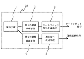
図1は、図2の制御・保護装置23を構成する地絡保護装置の構成及び動作を示したブロック図である。図1において、1は地絡検出手段、2は第1の継続確認手段、3はゲートブロック信号生成手段、4は第2の継続確認手段、5は遮断信号生成手段、23は制御・保護装置である。図1の地絡検出手段1は、図4に示した地絡検出用回路に相当する。
【0024】
図1に示すように、本発明は、地絡検出用回路すなわち地絡検出手段1から出力された検出信号の継続時間を調べることによって保護動作を行うものである。この保護動作自体は、制御・保護装置23が内蔵するマイコンのプログラムとして実施される。図3には、このプログラムのフローチャートを示した。
【0025】
本発明は、太陽電池のアレイ回路において地絡が生じた場合、地絡検出用回路が検出信号を出力し、その検出信号の継続時間を調べることによって、その後の動作を行う方法である。
【0026】
(1)まず、検出手段1および第1の継続確認手段2は、地絡が所定の第1の時限T1の間継続して発生していることを検出したときには、ゲートブロック信号生成手段3からゲートブロック信号をゲートブロック手段に対して出力する。
【0027】
(2)その後、第1の時限T1より長い第2の時限T2が経過してから、検出手段1および第2の継続確認手段4において、地絡が再び検出されたときには故障と判断して、遮断信号生成手段5から遮断指令信号を機械的な遮断手段に対して与え、地絡が再び検出されなかったときには前記ゲートブロック信号を解除する。
【0028】
本発明の方法は、このように2段階で保護動作を行うところに特徴がある。
【0029】
本例では、T1を0.2秒、T2を5秒に設定した。この程度の時間設定をしておけば、実用上十分な精度で保護動作が確実に実施されることを本発明者は見出した。ここで、T1およびT2の設定時間はT2がT1よりも長いことが必須であるが、それ以外には特に制限はない。しかしながら、実用的にはT1が0.01〜0.5秒程度、T2が数秒程度が好ましい。
【0030】
すなわち、本例では、地絡が0.2秒以上継続したときに、まずインバータのゲートブロックが行われてインバータの動作が停止し、その後地絡が5秒以上継続したときに初めて遮断動作が行われる。継続が5秒以下の時にはゲートブロックが解除されて、通常状態に戻る。
【0031】
このように早いタイミングでインバータを停止動作させてしまうので安全上には何等問題を与えず、一方では遮断動作までの時限を十分長く設定できるので、地絡の検出感度を上げても遮断装置の誤動作が起きにくく、遮断装置の接点寿命にも悪影響を与えずに済ませることができる。
【0032】
(比較例1)
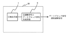
本例では、図5及び図6に基づき、従来の地絡保護装置を説明する。図5は装置の動作フローチャートであり、図6は装置の構成及び動作を示したブロック図である。図6において、1は地絡検出手段、6は遮断信号とゲートブロック信号生成手段、26は制御・保護装置である。
【0033】
図5に示すように、従来の地絡保護装置では、地絡があった場合はすぐに遮断装置を動かしている。従来、この遮断動作は、地絡を検出してから一定の時限をおいてから行われているが、本発明のように地絡を検出してから数秒間経過した後で遮断動作を行うことは安全上許容できなかった。何故ならば、その数秒間という時限の間はインバータが動作を継続してしまうためである。また、地絡検出手段の感度を上げて設定した場合には、誤動作が起きやすくなり頻繁に遮断動作が行われ、遮断手段の接点寿命が短くなるという問題もあった。
【0034】
(実施例2)
本例では、負荷として商用電力系統25の代わりに蛍光灯(100W、直管)を用いた点が実施例1と異なる。
【0035】
このように、商用電力系統とは未接続の状態にある独立型のシステムの場合は、連係インバータに必要な保護装置の多くが省略可能な場合が多い。本例では、実施例1に係る制御・保護装置23のプログラムを改変することで、その使用を可能とした。
【0036】
地絡検出回路と保護方式に関しては実施例1と全く同一の構成とした。太陽電池アレイとしては、多結晶モジュール(京セラ社製、LA361K54)を14枚使用して、14直列にして、アレイを構成した。
【0037】
実際に太陽電池モジュールの電極を大地に接触させることによって、わざとアレイ回路で地絡を生じさせて動作を確認したところ、実施例1と同様に地絡保護動作が可能であることが確認できた。
【0038】
このように独立型の太陽光発電システムであっても、本発明は十分にその目的を果たすことができることが分かった。
【0039】
【発明の効果】
以上説明したように、請求項1に係る発明によれば、太陽電池アレイの定期的な診断が可能となり、誤動作が低減し、長時間の運用においても高い信頼性を有する地絡保護装置がえられる。
【0040】
また、請求項2に係る発明によれば、以下の優れた効果を有する地絡保護装置並びにその動作方法、これを有した太陽光発電システム及びこれを有した太陽光発電システム用インバータの提供が可能となる。
【0041】
(1)検出感度を高く保った状態で、システムの不要な停止を防ぐことができるとともに、システムの発電効率も向上させることが可能となる。
【0042】
(2)システムの不要な停止を減らせるため、遮断装置の開閉回数を減らすことができ、接点の長寿命化が図れる。
【0043】
(3)検出感度が高く保てるため、微小が地絡でも検出することができ、システムの安全性を飛躍的に高めることが可能となる。
【図面の簡単な説明】
【図1】本発明に係る地絡保護装置の構成及び動作を示したブロック図である。
【図2】本発明に係る地絡保護装置を、系統連係型の太陽光発電システムに適用した場合を示すブロック図である。
【図3】本発明に係る地絡保護装置において保護動作を行うマイコンのプログラムのフローチャートである。
【図4】本発明に係る地絡保護装置の地絡検出用回路の一例を示す回路図である。
【図5】従来の地絡保護装置の動作を示すフローチャートである。
【図6】従来の地絡保護装置の構成及び動作を示したブロック図である。
【符号の説明】
1 地絡検出手段、
2 第1の継続確認手段、
3 ゲートブロック信号生成手段、
4 第2の継続確認手段、
5 遮断信号生成手段、
6 遮断信号とゲートブロック信号生成手段、
11、12、13、14、15 抵抗、
16 電圧差の絶対値検出回路、
17 閾値との比較回路、
21 太陽電池アレイ、
22 インバータ、
23、26 制御・保護装置、
24 遮断装置、
25 電力系統。[0001]
[Industrial applications]
The present invention relates to a ground fault protection device and an operation method thereof, a solar power generation system having the same, and an inverter for a solar power generation system having the same. More specifically, a ground fault protection device and an operation method thereof, which can prevent unnecessary stoppage of a photovoltaic power generation system while maintaining high detection sensitivity for a ground fault generated inside a solar cell array, The present invention relates to a solar power generation system and an inverter for a solar power generation system having the same.
[0002]
[Prior art]
The solar cell array is formed by connecting a plurality of solar cells in series / parallel, and is installed and used outdoors so that each solar cell is sufficiently irradiated with sunlight. Therefore, for example, in one solar cell, a short-circuit with the ground potential due to erroneous contact with a conductive object (for example, an animal or a human being as well as a metal body) (hereinafter, this phenomenon is referred to as a ground fault) occurs. If this occurs, the operation of the photovoltaic power generation system incorporating the photovoltaic array must be temporarily stopped for safety measures. Such a shutdown of the system has a significant effect on the load to which the system is connected.
[0003]
FIG. 2 is a configuration diagram showing an example of a system-linked solar power generation system provided with a control / protection device as the above countermeasure. In FIG. 2, 21 is a solar cell array, 22 is an inverter, 23 is a control / protection device, 24 is a shutoff device, and 25 is a power system.
[0004]
In the system shown in FIG. 2, the
[0005]
In particular, the following protection operation has been generally adopted for the latter ground fault abnormality.
(1) Prior art 1 (instantaneous stop type): a method of responding instantly and shutting down the system when a ground fault abnormality is detected.
(2) Prior art 2 (constant timed stop type): a method in which when a ground fault abnormality is detected, a shutoff operation is performed after a certain time has passed. The fixed time is generally about 0.5 seconds or less.
[0006]
However, the above prior art has the following problems.
[0007]
{Circle around (1)} The method of performing the shutoff operation instantaneously (Prior Art 1) has a problem that it is likely to malfunction due to the incorporation of noise or the like, and the detection sensitivity cannot be increased so much. If a malfunction occurs frequently, the number of times of mechanical opening / closing of the contacts of the
[0008]
(2) In the method in which a fixed time period is set before interruption (prior art 2), if the operation time period is short, malfunctions are likely to occur, so that it is difficult to increase the detection sensitivity. If this time period is set long, the protection operation will be performed. There is a problem in that the protection itself does not play a role because it itself becomes slow.
[0009]
[Problems to be solved by the invention]
The present invention provides a ground fault protection device, an operation method thereof, and a sun having the same, which can prevent unnecessary stoppage of a photovoltaic power generation system while maintaining high detection sensitivity for a ground fault generated inside a solar cell array. It is an object of the present invention to provide a photovoltaic power generation system and a photovoltaic power generation system inverter having the same.
[0010]
[Means for Solving the Problems]
Ground fault protection device of the present invention, when a ground fault inside the solar cell array occurs, a gate block signal to the gate block means provided between the load and the solar cell array, the solar cell A shutoff command signal is individually output to a mechanical shutoff means provided between the array and the load,
And, e Bei and ground fault detection means and time measurement means,
Further, using the ground fault detecting means and the time measuring means,
When detecting that the ground fault has continuously occurred during the predetermined first time period T1, outputs a gate block signal to the gate block means;
Thereafter, after a second time period T2 longer than the first time period T1 has elapsed, when a ground fault is detected again, it is determined that a failure has occurred, and a shutoff command signal is given to the mechanical shutoff means.
When the ground fault is not detected again, the gate block signal is released .
[0011]
By using the time measuring means, the presence or absence of the occurrence of a ground fault inside the solar cell array can be checked by the ground fault detecting means at a predetermined time and at a predetermined time interval. This makes it possible to obtain a ground fault protection device having high reliability even in long-time operation since malfunctions are reduced.
[0012]
In the above feature, the ground fault protection device may use the ground fault detecting unit and the time measuring unit to detect that a ground fault has continuously occurred during a predetermined first time period T1. A gate block signal is output to the gate block means. After that, when a second time period T2 longer than the first time period T1 has elapsed, when a ground fault is detected again, it is determined that a failure has occurred and a cutoff command is issued. A signal is given to the mechanical shut-off means, and when a ground fault is not detected again, the gate block signal is released. Only the gate block operation without interruption is performed to stop the inverter, and then mechanical interruption (separation from the power system) is performed only when a ground fault is detected after the time T2 has elapsed. Utoyuu control becomes possible. Therefore, even if the detection sensitivity of the ground fault detecting means is increased, mechanical interruption due to erroneous detection can be reduced, and the life of the interruption means can be extended. In addition, since the operation of the inverter itself is stopped when the first ground fault is detected, the purpose of the protection operation (securing safety) is not impaired unlike the case where the time limit is lengthened in the related art.
[0013]
The above-described operation method of the ground fault protection device including the ground fault detecting means and the time measuring means is configured such that the light ground fault is detected when it is detected that the ground fault has continuously occurred during the predetermined first time period T1. A first step of generating a signal; a second step of checking again for the presence or absence of a ground fault after a lapse of a second time period T2 longer than the first time period T1 after the first step; When the ground fault is detected again in the second step, it is determined that a failure has occurred, and a severe ground fault signal is generated. When the ground fault is not detected again in the second step, the light ground fault signal is released. And a step.
[0014]
BEST MODE FOR CARRYING OUT THE INVENTION
Hereinafter, a ground fault protection device and an operation method thereof according to the present invention, a photovoltaic power generation system including the same, and a photovoltaic power generation system inverter including the same will be specifically described.
[0015]
(Example 1)
FIG. 2 is a block diagram showing a case where the ground fault protection device according to the present invention is applied to a grid-linked solar power generation system. In FIG. 2, 21 is a solar cell array, 22 is an inverter, 23 is a control / protection device, 24 is a shutoff device, and 25 is a power system. The
[0016]
In this example, a roof material integrated solar cell module made by Canon (product model BS-03) was connected in 14 series and 4 parallel, and used as a 3360 W solar cell array.
[0017]
The
[0018]
FIG. 4 is an example of a ground fault detection circuit of the ground fault protection device constituting the control /
[0019]
This circuit includes a circuit provided with a resistor 11 and a resistor 12 connected in series and a circuit provided with a resistor 13 and a resistor 14 connected in series, in parallel with the
[0020]
In this example, 10V was adopted as this threshold. This is approximately 0.5 MΩ when converted to insulation resistance, which is extremely high as the sensitivity of the ground fault protection device. Conventionally, the setting of this threshold value is usually 50 V or more (100 KΩ or less in terms of insulation resistance), and the detection sensitivity has been suppressed so as not to cause malfunction.
[0021]
As the detection circuit, a known method such as a circuit utilizing a current difference between positive and negative circuits of the array circuit can be used as appropriate.
[0022]
The detection signal is input to the control /
[0023]
FIG. 1 is a block diagram showing the configuration and operation of the ground fault protection device constituting the control /
[0024]
As shown in FIG. 1, the present invention performs a protection operation by checking the duration of a detection signal output from a ground fault detection circuit, that is, a ground fault detection means 1. This protection operation itself is implemented as a program of a microcomputer built in the control /
[0025]
The present invention is a method in which, when a ground fault occurs in an array circuit of a solar cell, a ground fault detection circuit outputs a detection signal and checks the duration of the detection signal to perform a subsequent operation.
[0026]
(1) First, when the detecting means 1 and the first
[0027]
(2) After that, after the second time period T2 longer than the first time period T1 has elapsed, the detection means 1 and the second continuation confirmation means 4 determine that a fault has occurred when a ground fault is detected again. A shutoff command signal is supplied from the shutoff signal generating means 5 to the mechanical shutoff means, and when the ground fault is not detected again, the gate block signal is released.
[0028]
The method of the present invention is characterized in that the protection operation is performed in two stages as described above.
[0029]
In this example, T1 was set to 0.2 seconds and T2 was set to 5 seconds. The present inventor has found that if the time is set to such a degree, the protection operation is reliably performed with sufficient accuracy for practical use. Here, the setting time of T1 and T2 is indispensable that T2 is longer than T1, but there is no particular limitation. However, practically, T1 is preferably about 0.01 to 0.5 seconds, and T2 is preferably about several seconds.
[0030]
That is, in this example, when a ground fault continues for 0.2 seconds or more, first, the inverter gate block is performed to stop the operation of the inverter, and thereafter, when the ground fault continues for 5 seconds or more, the shutoff operation is performed. Done. If the continuation is for 5 seconds or less, the gate block is released and returns to the normal state.
[0031]
Since the inverter is stopped at such an early timing, there is no problem in terms of safety.On the other hand, the time limit until the shut-off operation can be set sufficiently long. Malfunction is less likely to occur, and the contact life of the breaking device can be prevented from being adversely affected.
[0032]
(Comparative Example 1)
In this example, a conventional ground fault protection device will be described with reference to FIGS. FIG. 5 is an operation flowchart of the apparatus, and FIG. 6 is a block diagram showing the configuration and operation of the apparatus. In FIG. 6, 1 is a ground fault detecting means, 6 is a cutoff signal and gate block signal generating means, and 26 is a control / protection device.
[0033]
As shown in FIG. 5, in the conventional ground fault protection device, when a ground fault occurs, the shutoff device is immediately moved. Conventionally, this shutoff operation has been performed after a certain time period has elapsed since the detection of the ground fault.However, as in the present invention, the shutoff operation is performed several seconds after the detection of the ground fault. Was unacceptable for safety. This is because the inverter continues to operate during the time period of several seconds. In addition, when the sensitivity of the ground fault detecting means is set to be higher, a malfunction is likely to occur, and the breaking operation is frequently performed, so that the contact life of the breaking means is shortened.
[0034]
(Example 2)
This embodiment differs from the first embodiment in that a fluorescent lamp (100 W, straight tube) is used instead of the
[0035]
As described above, in the case of a stand-alone system that is not connected to the commercial power system, many of the protection devices required for the linked inverter can often be omitted. In this example, the program of the control /
[0036]
With respect to the ground fault detection circuit and the protection method, the configuration is exactly the same as that of the first embodiment. As the solar cell array, 14 polycrystalline modules (manufactured by Kyocera Corporation, LA361K54) were used, and the array was configured in 14 series.
[0037]
When the electrode of the solar cell module was actually brought into contact with the ground to intentionally generate a ground fault in the array circuit, and the operation was confirmed, it was confirmed that the ground fault protection operation was possible as in Example 1. .
[0038]
As described above, it has been found that the present invention can sufficiently achieve the object even with a stand-alone solar power generation system.
[0039]
【The invention's effect】
As described above, according to the first aspect of the present invention, it is possible to periodically diagnose a solar cell array, reduce a malfunction, and obtain a ground fault protection device having high reliability even in long-time operation. Can be
[0040]
According to the second aspect of the present invention, there are provided a ground fault protection device having the following excellent effects, an operation method thereof, a solar power generation system having the same, and an inverter for a solar power generation system having the same. It becomes possible.
[0041]
(1) While the detection sensitivity is kept high, unnecessary stoppage of the system can be prevented, and the power generation efficiency of the system can be improved.
[0042]
(2) Since unnecessary stoppage of the system can be reduced, the number of times of opening and closing of the shutoff device can be reduced, and the life of the contact can be extended.
[0043]
(3) Since the detection sensitivity can be kept high, even a minute ground fault can be detected, and the safety of the system can be dramatically improved.
[Brief description of the drawings]
FIG. 1 is a block diagram showing a configuration and operation of a ground fault protection device according to the present invention.
FIG. 2 is a block diagram showing a case where the ground fault protection device according to the present invention is applied to a system-linked solar power generation system.
FIG. 3 is a flowchart of a program of a microcomputer that performs a protection operation in the ground fault protection device according to the present invention.
FIG. 4 is a circuit diagram showing an example of a ground fault detection circuit of the ground fault protection device according to the present invention.
FIG. 5 is a flowchart showing the operation of the conventional ground fault protection device.
FIG. 6 is a block diagram showing the configuration and operation of a conventional ground fault protection device.
[Explanation of symbols]
1 ground fault detection means,
2 First continuation confirmation means,
3 gate block signal generating means,
4 Second continuation confirmation means,
5 cutoff signal generating means,
6. Cutoff signal and gate block signal generation means,
11, 12, 13, 14, 15 resistance,
16 Absolute value detection circuit of voltage difference,
17 threshold value comparison circuit,
21 solar array,
22 inverter,
23, 26 control and protection devices,
24 shut-off device,
25 Power system.
Claims (4)
かつ、地絡検出手段と時間計測手段とを備え、
さらに、前記地絡検出手段及び前記時間計測手段を用いて、
地絡が所定の第1の時限T1の間継続して発生していることを検出したときにはゲートブロック信号を前記ゲートブロック手段に対して出力し、
その後、前記第1の時限T1より長い第2の時限T2が経過してから、地絡が再び検出されたときには故障と判断して遮断指令信号を前記機械的な遮断手段に対して与え、
地絡が再び検出されなかったときには前記ゲートブロック信号を解除する
ことを特徴とする地絡保護装置。When a ground fault occurred inside the solar cell array, a gate block signal was provided between the solar cell array and the load for a gate block means provided between the solar cell array and the load . cutoff command signal to mechanical blocking means, and outputs separately,
And, e Bei and ground fault detection means and time measurement means,
Further, using the ground fault detecting means and the time measuring means,
When detecting that the ground fault has continuously occurred during the predetermined first time period T1, outputs a gate block signal to the gate block means;
Thereafter, after a second time period T2 longer than the first time period T1 has elapsed, when a ground fault is detected again, it is determined that a failure has occurred, and a shutoff command signal is given to the mechanical shutoff means.
The ground fault protection device cancels the gate block signal when a ground fault is not detected again .
地絡が所定の第1の時限T1の間継続して発生していることを検出したときには軽度地絡信号を生成する第1工程と、
前記第1工程の後、前記第1の時限T1より長い第2の時限T2が経過してから、再び地絡の有無を検査する第2の工程と、
前記第2工程において地絡が再び検出されたときには故障と判断して重度地絡信号を生成し、前記第2工程において地絡が再び検出されなかったときには前記軽度地絡信号を解除する第3の工程と、
を有することを特徴とする地絡保護装置の動作方法。In an operation method of a ground fault protection device including a ground fault detection unit and a time measurement unit,
A first step of generating a light ground fault signal when detecting that a ground fault has continuously occurred during a predetermined first time period T1;
After the first step, after a second time period T2 longer than the first time period T1 has elapsed, a second step of checking again for the presence or absence of a ground fault;
When the ground fault is detected again in the second step, it is determined that a failure has occurred, and a severe ground fault signal is generated. When the ground fault is not detected again in the second step, the light ground fault signal is released. Process and
An operation method of a ground fault protection device, comprising:
Priority Applications (7)
| Application Number | Priority Date | Filing Date | Title |
|---|---|---|---|
| JP15674597A JP3565470B2 (en) | 1997-06-13 | 1997-06-13 | Ground fault protection device and operation method thereof, photovoltaic power generation system having the same, and inverter for photovoltaic power generation system having the same |
| EP98110230A EP0884817B1 (en) | 1997-06-13 | 1998-06-04 | Ground fault protecting apparatus and method for solar power generation and solar power generation apparatus using the apparatus and method |
| DE69809841T DE69809841T2 (en) | 1997-06-13 | 1998-06-04 | Method and device for earth fault protection of a solar power system and solar power system using the method and the device |
| US09/092,870 US6101073A (en) | 1997-06-13 | 1998-06-08 | Ground fault protecting apparatus and method for solar power generation and solar power generation apparatus using the apparatus and method |
| AU71830/98A AU707400B2 (en) | 1997-06-13 | 1998-06-12 | Ground fault protecting apparatus and method for solar power generation and solar power generation apparatus using the apparatus and method |
| KR10-1998-0022008A KR100384426B1 (en) | 1997-06-13 | 1998-06-12 | Ground fault protecting apparatus and method for solar power generation and solar power generation apparatus using the apparatus and method |
| CN98114755A CN1080475C (en) | 1997-06-13 | 1998-06-12 | Ground fault protecting apparatus and method for solar power generation and solar power generation apparatus using apparatus and method |
Applications Claiming Priority (1)
| Application Number | Priority Date | Filing Date | Title |
|---|---|---|---|
| JP15674597A JP3565470B2 (en) | 1997-06-13 | 1997-06-13 | Ground fault protection device and operation method thereof, photovoltaic power generation system having the same, and inverter for photovoltaic power generation system having the same |
Publications (2)
| Publication Number | Publication Date |
|---|---|
| JPH118929A JPH118929A (en) | 1999-01-12 |
| JP3565470B2 true JP3565470B2 (en) | 2004-09-15 |
Family
ID=15634397
Family Applications (1)
| Application Number | Title | Priority Date | Filing Date |
|---|---|---|---|
| JP15674597A Expired - Fee Related JP3565470B2 (en) | 1997-06-13 | 1997-06-13 | Ground fault protection device and operation method thereof, photovoltaic power generation system having the same, and inverter for photovoltaic power generation system having the same |
Country Status (7)
| Country | Link |
|---|---|
| US (1) | US6101073A (en) |
| EP (1) | EP0884817B1 (en) |
| JP (1) | JP3565470B2 (en) |
| KR (1) | KR100384426B1 (en) |
| CN (1) | CN1080475C (en) |
| AU (1) | AU707400B2 (en) |
| DE (1) | DE69809841T2 (en) |
Families Citing this family (102)
| Publication number | Priority date | Publication date | Assignee | Title |
|---|---|---|---|---|
| JP2001161032A (en) * | 1999-12-01 | 2001-06-12 | Canon Inc | System interconnection power conditioner and power generating system using the same |
| US6593520B2 (en) * | 2000-02-29 | 2003-07-15 | Canon Kabushiki Kaisha | Solar power generation apparatus and control method therefor |
| JP2001275259A (en) | 2000-03-29 | 2001-10-05 | Canon Inc | Linked system inverter and distributed power generation system |
| US6653549B2 (en) * | 2000-07-10 | 2003-11-25 | Canon Kabushiki Kaisha | Photovoltaic power generation systems and methods of controlling photovoltaic power generation systems |
| JP4463963B2 (en) * | 2000-09-29 | 2010-05-19 | キヤノン株式会社 | Grid interconnection device |
| JP2002112553A (en) | 2000-09-29 | 2002-04-12 | Canon Inc | Power converter, its control method, and generator |
| US7733069B2 (en) | 2000-09-29 | 2010-06-08 | Canon Kabushiki Kaisha | Power converting apparatus and power generating apparatus |
| JP2002204531A (en) | 2000-10-31 | 2002-07-19 | Canon Inc | Ac-interconnecting device and control method thereof |
| JP2002318162A (en) * | 2001-02-01 | 2002-10-31 | Canon Inc | Detection method and protection device of malfunction, and estimation method and estimation device of temperature |
| JP2002233045A (en) | 2001-02-02 | 2002-08-16 | Canon Inc | Ground detecting device for photovoltaic power generation system and method |
| JP2002252986A (en) * | 2001-02-26 | 2002-09-06 | Canon Inc | Inverter, power supply system and method for reducing leakage current in power supply system |
| JP2002359387A (en) * | 2001-06-01 | 2002-12-13 | Canon Inc | Solar battery installation structure and solar power generation system |
| JP2003098215A (en) * | 2001-09-26 | 2003-04-03 | Canon Inc | Earth detection method and device in power conversion system |
| JP2003180036A (en) * | 2001-10-01 | 2003-06-27 | Canon Inc | Power converter, power conversion system, and method of detecting single operation |
| EP1616378A1 (en) * | 2003-04-15 | 2006-01-18 | Koninklijke Philips Electronics N.V. | Solar power system |
| JP2005312138A (en) * | 2004-04-19 | 2005-11-04 | Canon Inc | Power controller, power generation system and power system |
| CN100550562C (en) * | 2004-12-27 | 2009-10-14 | 丹福斯驱动器公司 | Be used for detecting the method for the earth-fault conditions of motor controller |
| US20060250783A1 (en) * | 2005-04-07 | 2006-11-09 | Taylor Bill W F | Inverter operation modes |
| US7397653B2 (en) * | 2005-04-07 | 2008-07-08 | Pv Powered, Inc. | Inverter design |
| US20070086215A1 (en) * | 2005-04-07 | 2007-04-19 | Bill Taylor | Inverter operation modes |
| US7502241B2 (en) * | 2005-04-07 | 2009-03-10 | Pv Powered, Inc. | Inverter startup algorithm |
| US20060227472A1 (en) * | 2005-04-07 | 2006-10-12 | William Taylor | Inverter ground fault circuit |
| US20060250828A1 (en) * | 2005-04-07 | 2006-11-09 | Bill Taylor | Inverter power electronics design |
| US7738228B2 (en) * | 2005-04-07 | 2010-06-15 | Pv Powered, Inc. | Inverter thermal protection |
| US7432618B2 (en) * | 2005-04-07 | 2008-10-07 | Pv Powered, Inc. | Inverter anti-islanding method |
| CN101180786B (en) | 2005-11-22 | 2012-06-20 | 罗姆股份有限公司 | Inverter, its control circuit, and light emitting device and liquid crystal television using the same |
| US11881814B2 (en) | 2005-12-05 | 2024-01-23 | Solaredge Technologies Ltd. | Testing of a photovoltaic panel |
| US10693415B2 (en) | 2007-12-05 | 2020-06-23 | Solaredge Technologies Ltd. | Testing of a photovoltaic panel |
| US7906870B2 (en) * | 2006-10-13 | 2011-03-15 | Pv Powered, Inc. | System and method for anti-islanding, such as anti-islanding for a grid-connected photovoltaic inverter |
| US11687112B2 (en) | 2006-12-06 | 2023-06-27 | Solaredge Technologies Ltd. | Distributed power harvesting systems using DC power sources |
| US11309832B2 (en) | 2006-12-06 | 2022-04-19 | Solaredge Technologies Ltd. | Distributed power harvesting systems using DC power sources |
| US11735910B2 (en) | 2006-12-06 | 2023-08-22 | Solaredge Technologies Ltd. | Distributed power system using direct current power sources |
| US11855231B2 (en) | 2006-12-06 | 2023-12-26 | Solaredge Technologies Ltd. | Distributed power harvesting systems using DC power sources |
| US8013472B2 (en) | 2006-12-06 | 2011-09-06 | Solaredge, Ltd. | Method for distributed power harvesting using DC power sources |
| US8816535B2 (en) | 2007-10-10 | 2014-08-26 | Solaredge Technologies, Ltd. | System and method for protection during inverter shutdown in distributed power installations |
| US9112379B2 (en) | 2006-12-06 | 2015-08-18 | Solaredge Technologies Ltd. | Pairing of components in a direct current distributed power generation system |
| US9088178B2 (en) | 2006-12-06 | 2015-07-21 | Solaredge Technologies Ltd | Distributed power harvesting systems using DC power sources |
| US8319483B2 (en) | 2007-08-06 | 2012-11-27 | Solaredge Technologies Ltd. | Digital average input current control in power converter |
| US9130401B2 (en) | 2006-12-06 | 2015-09-08 | Solaredge Technologies Ltd. | Distributed power harvesting systems using DC power sources |
| US8947194B2 (en) | 2009-05-26 | 2015-02-03 | Solaredge Technologies Ltd. | Theft detection and prevention in a power generation system |
| US11888387B2 (en) | 2006-12-06 | 2024-01-30 | Solaredge Technologies Ltd. | Safety mechanisms, wake up and shutdown methods in distributed power installations |
| US8473250B2 (en) | 2006-12-06 | 2013-06-25 | Solaredge, Ltd. | Monitoring of distributed power harvesting systems using DC power sources |
| US11569659B2 (en) | 2006-12-06 | 2023-01-31 | Solaredge Technologies Ltd. | Distributed power harvesting systems using DC power sources |
| US8319471B2 (en) | 2006-12-06 | 2012-11-27 | Solaredge, Ltd. | Battery power delivery module |
| US11728768B2 (en) | 2006-12-06 | 2023-08-15 | Solaredge Technologies Ltd. | Pairing of components in a direct current distributed power generation system |
| US8963369B2 (en) | 2007-12-04 | 2015-02-24 | Solaredge Technologies Ltd. | Distributed power harvesting systems using DC power sources |
| US11296650B2 (en) | 2006-12-06 | 2022-04-05 | Solaredge Technologies Ltd. | System and method for protection during inverter shutdown in distributed power installations |
| US8384243B2 (en) | 2007-12-04 | 2013-02-26 | Solaredge Technologies Ltd. | Distributed power harvesting systems using DC power sources |
| US8618692B2 (en) | 2007-12-04 | 2013-12-31 | Solaredge Technologies Ltd. | Distributed power system using direct current power sources |
| JP5176330B2 (en) * | 2007-01-18 | 2013-04-03 | パナソニック株式会社 | Fuel cell system |
| US11228278B2 (en) | 2007-11-02 | 2022-01-18 | Tigo Energy, Inc. | System and method for enhanced watch dog in solar panel installations |
| US8933321B2 (en) | 2009-02-05 | 2015-01-13 | Tigo Energy, Inc. | Systems and methods for an enhanced watchdog in solar module installations |
| US8823218B2 (en) | 2007-11-02 | 2014-09-02 | Tigo Energy, Inc. | System and method for enhanced watch dog in solar panel installations |
| US7884278B2 (en) * | 2007-11-02 | 2011-02-08 | Tigo Energy, Inc. | Apparatuses and methods to reduce safety risks associated with photovoltaic systems |
| CN101933209B (en) | 2007-12-05 | 2015-10-21 | 太阳能安吉有限公司 | Release mechanism in distributed electrical power apparatus, to wake up and method for closing |
| US8049523B2 (en) | 2007-12-05 | 2011-11-01 | Solaredge Technologies Ltd. | Current sensing on a MOSFET |
| US11264947B2 (en) | 2007-12-05 | 2022-03-01 | Solaredge Technologies Ltd. | Testing of a photovoltaic panel |
| EP2232690B1 (en) | 2007-12-05 | 2016-08-31 | Solaredge Technologies Ltd. | Parallel connected inverters |
| US9291696B2 (en) | 2007-12-05 | 2016-03-22 | Solaredge Technologies Ltd. | Photovoltaic system power tracking method |
| WO2009118682A2 (en) | 2008-03-24 | 2009-10-01 | Solaredge Technolgies Ltd. | Zero current switching |
| EP2107589B1 (en) * | 2008-03-31 | 2012-05-16 | SMA Solar Technology AG | Switching device for grounding an inverter |
| JP5111208B2 (en) * | 2008-04-04 | 2013-01-09 | 日立オートモティブシステムズ株式会社 | Power converter |
| WO2009136358A1 (en) | 2008-05-05 | 2009-11-12 | Solaredge Technologies Ltd. | Direct current power combiner |
| US8189306B2 (en) * | 2009-03-13 | 2012-05-29 | Raytheon Company | Dynamic grounding system and method |
| JP2011071346A (en) * | 2009-09-25 | 2011-04-07 | Sansha Electric Mfg Co Ltd | Monitoring device |
| US8854193B2 (en) | 2009-12-29 | 2014-10-07 | Tigo Energy, Inc. | Systems and methods for remote or local shut-off of a photovoltaic system |
| ITRM20100008A1 (en) * | 2010-01-13 | 2011-07-14 | Solsonica S P A | PHOTOVOLTAIC MODULE WITH FIRE PROTECTION. |
| GB2485527B (en) | 2010-11-09 | 2012-12-19 | Solaredge Technologies Ltd | Arc detection and prevention in a power generation system |
| US10230310B2 (en) | 2016-04-05 | 2019-03-12 | Solaredge Technologies Ltd | Safety switch for photovoltaic systems |
| US10673229B2 (en) | 2010-11-09 | 2020-06-02 | Solaredge Technologies Ltd. | Arc detection and prevention in a power generation system |
| US10673222B2 (en) | 2010-11-09 | 2020-06-02 | Solaredge Technologies Ltd. | Arc detection and prevention in a power generation system |
| GB2486408A (en) | 2010-12-09 | 2012-06-20 | Solaredge Technologies Ltd | Disconnection of a string carrying direct current |
| GB2483317B (en) | 2011-01-12 | 2012-08-22 | Solaredge Technologies Ltd | Serially connected inverters |
| US8547669B2 (en) | 2011-01-12 | 2013-10-01 | Schneider Electric USA, Inc. | Arc fault mitigation for photovoltaic systems |
| DE102011017051B4 (en) * | 2011-04-11 | 2016-12-22 | Phoenix Contact Gmbh & Co. Kg | Monitoring device for an isolated network of a photovoltaic system, a photovoltaic system with such a monitoring device and a method for safe operation of a photovoltaic system |
| ES2769404T3 (en) * | 2011-07-08 | 2020-06-25 | Sma Solar Technology Ag | Integrated 3-level elevator / inverter for DC sources network coupling, power generation plant and operating procedure |
| US20130015875A1 (en) * | 2011-07-13 | 2013-01-17 | United Solar Ovonic Llc | Failure detection system for photovoltaic array |
| JP5777965B2 (en) * | 2011-07-22 | 2015-09-16 | 京セラ株式会社 | Fault diagnosis method, grid interconnection device, and control device |
| US8570005B2 (en) | 2011-09-12 | 2013-10-29 | Solaredge Technologies Ltd. | Direct current link circuit |
| GB2498365A (en) | 2012-01-11 | 2013-07-17 | Solaredge Technologies Ltd | Photovoltaic module |
| GB2498791A (en) | 2012-01-30 | 2013-07-31 | Solaredge Technologies Ltd | Photovoltaic panel circuitry |
| GB2498790A (en) | 2012-01-30 | 2013-07-31 | Solaredge Technologies Ltd | Maximising power in a photovoltaic distributed power system |
| US9853565B2 (en) | 2012-01-30 | 2017-12-26 | Solaredge Technologies Ltd. | Maximized power in a photovoltaic distributed power system |
| GB2499991A (en) | 2012-03-05 | 2013-09-11 | Solaredge Technologies Ltd | DC link circuit for photovoltaic array |
| KR101222249B1 (en) | 2012-04-25 | 2013-01-16 | 김윤중 | The auto-shotdown module of the stand alone solar invertor and its method |
| US10115841B2 (en) | 2012-06-04 | 2018-10-30 | Solaredge Technologies Ltd. | Integrated photovoltaic panel circuitry |
| KR101204263B1 (en) | 2012-08-06 | 2012-11-23 | 이광현 | Solar pannel error detector for solar generation |
| JP5950454B2 (en) * | 2012-09-24 | 2016-07-13 | 新電元工業株式会社 | Ground fault detection circuit |
| GB201303207D0 (en) | 2013-02-22 | 2013-04-10 | Control Tech Ltd | GFDI using standard industrial modules |
| US9941813B2 (en) | 2013-03-14 | 2018-04-10 | Solaredge Technologies Ltd. | High frequency multi-level inverter |
| US9548619B2 (en) | 2013-03-14 | 2017-01-17 | Solaredge Technologies Ltd. | Method and apparatus for storing and depleting energy |
| EP3506370B1 (en) | 2013-03-15 | 2023-12-20 | Solaredge Technologies Ltd. | Bypass mechanism |
| JP2015018838A (en) * | 2013-07-08 | 2015-01-29 | 木谷電器株式会社 | Fault detector of backflow prevention diode for solar cell, fault detection system of backflow prevention diode for solar cell, and fault detection method of backflow prevention diode for solar cell |
| US9318974B2 (en) | 2014-03-26 | 2016-04-19 | Solaredge Technologies Ltd. | Multi-level inverter with flying capacitor topology |
| CN107148735B (en) | 2014-12-15 | 2019-05-28 | 日立汽车系统株式会社 | Power inverter |
| US11018623B2 (en) | 2016-04-05 | 2021-05-25 | Solaredge Technologies Ltd. | Safety switch for photovoltaic systems |
| US11177663B2 (en) | 2016-04-05 | 2021-11-16 | Solaredge Technologies Ltd. | Chain of power devices |
| CN110754034B (en) * | 2017-07-18 | 2021-07-16 | 东芝三菱电机产业系统株式会社 | Ground fault detector and power conditioner |
| EP3713029A1 (en) * | 2019-03-18 | 2020-09-23 | Siemens Aktiengesellschaft | Locating an earth fault in a dc network with multiple load zones |
| US11088535B2 (en) | 2019-04-12 | 2021-08-10 | Raytheon Company | Fast ground fault circuit protection |
| WO2021028039A1 (en) * | 2019-08-14 | 2021-02-18 | Abb Schweiz Ag | Direct current power supply assembly provided with fault detection system |
| US20230216429A1 (en) * | 2020-04-27 | 2023-07-06 | Toshiba Mitsubishi-Electric Industrial Systems Corporation | Electric power conversion apparatus and electric power conversion system |
Family Cites Families (9)
| Publication number | Priority date | Publication date | Assignee | Title |
|---|---|---|---|---|
| JPH04210779A (en) * | 1990-12-14 | 1992-07-31 | Mitsubishi Electric Corp | Ground fault detector for inverter unit and detecting method |
| JP2766407B2 (en) * | 1991-08-20 | 1998-06-18 | 株式会社東芝 | Inverter control device for photovoltaic power generation |
| JPH07264873A (en) * | 1994-03-18 | 1995-10-13 | Toshiba Corp | Power converter |
| US5669987A (en) * | 1994-04-13 | 1997-09-23 | Canon Kabushiki Kaisha | Abnormality detection method, abnormality detection apparatus, and solar cell power generating system using the same |
| JPH08275390A (en) * | 1995-03-29 | 1996-10-18 | Canon Inc | Method and apparatus for controlling charging and discharging, and power generating system having such apparatus |
| JPH08280143A (en) * | 1995-04-10 | 1996-10-22 | Fuji Electric Co Ltd | Method of automatically switching power feed route to inverter from commercial power supply |
| JP3368124B2 (en) * | 1995-10-26 | 2003-01-20 | キヤノン株式会社 | Overcharge prevention circuit |
| JPH09285015A (en) * | 1996-04-08 | 1997-10-31 | Sanyo Electric Co Ltd | Dc ground detector of photovoltaic power generation system |
| JP3554116B2 (en) * | 1996-09-06 | 2004-08-18 | キヤノン株式会社 | Power control device and solar power generation system using the same |
-
1997
- 1997-06-13 JP JP15674597A patent/JP3565470B2/en not_active Expired - Fee Related
-
1998
- 1998-06-04 EP EP98110230A patent/EP0884817B1/en not_active Expired - Lifetime
- 1998-06-04 DE DE69809841T patent/DE69809841T2/en not_active Expired - Lifetime
- 1998-06-08 US US09/092,870 patent/US6101073A/en not_active Expired - Lifetime
- 1998-06-12 AU AU71830/98A patent/AU707400B2/en not_active Ceased
- 1998-06-12 CN CN98114755A patent/CN1080475C/en not_active Expired - Fee Related
- 1998-06-12 KR KR10-1998-0022008A patent/KR100384426B1/en not_active IP Right Cessation
Also Published As
| Publication number | Publication date |
|---|---|
| KR19990006937A (en) | 1999-01-25 |
| CN1080475C (en) | 2002-03-06 |
| EP0884817B1 (en) | 2002-12-04 |
| JPH118929A (en) | 1999-01-12 |
| DE69809841D1 (en) | 2003-01-16 |
| KR100384426B1 (en) | 2003-07-16 |
| US6101073A (en) | 2000-08-08 |
| AU7183098A (en) | 1998-12-17 |
| EP0884817A3 (en) | 1999-05-19 |
| AU707400B2 (en) | 1999-07-08 |
| EP0884817A2 (en) | 1998-12-16 |
| DE69809841T2 (en) | 2003-05-28 |
| CN1202752A (en) | 1998-12-23 |
Similar Documents
| Publication | Publication Date | Title |
|---|---|---|
| JP3565470B2 (en) | Ground fault protection device and operation method thereof, photovoltaic power generation system having the same, and inverter for photovoltaic power generation system having the same | |
| JP6547447B2 (en) | Power recovery method for photovoltaic system and device therefor | |
| KR102174451B1 (en) | Solar power unit having the function of ground fault detection | |
| JPH07177652A (en) | Solar beam power generation system and protective system therefor | |
| KR20090129775A (en) | Dc feeder groundfault detector | |
| CN104635102A (en) | Electronic component detection device and detection method thereof | |
| WO2024067317A1 (en) | Photovoltaic system, and circuit protection method for photovoltaic system | |
| CN108054998A (en) | A kind of optimizer, photovoltaic generating system and photovoltaic generation control method | |
| EP2503849B1 (en) | Discreet input signal generation via output short-circuit detection | |
| CN207968420U (en) | A kind of optimizer and photovoltaic generating system | |
| JP2014011430A (en) | Current controller for solar cell inspection | |
| WO2022091250A1 (en) | Protection system, solar power generation system, and protection method | |
| JPH09140051A (en) | Power supply equipment | |
| CN111555710A (en) | PLC (programmable logic controller) driving circuit of photovoltaic shutoff device and control method thereof | |
| KR101639940B1 (en) | Apparatus and method for monitoring pv panel | |
| JPH0254025B2 (en) | ||
| WO2022168255A1 (en) | Arc detector, breaker, power conditioner, solar panel, solar panel-attached module, connection box, arc detection system, and arc detection method | |
| CN210136418U (en) | Monitoring circuit and relay protection device | |
| CN106996863B (en) | Laser optical path detection circuit and failure detection method thereof | |
| EP0887628A1 (en) | Fail-safe system | |
| JP3533090B2 (en) | Solar power system | |
| CN220440375U (en) | Pure hardware protection circuit for detecting abnormal temperature of inverter | |
| CN111044573B (en) | Fault detection circuit and method for gas sensor | |
| JPS59206772A (en) | Instantaneous power failure detector | |
| JP2010231490A (en) | Circuit board for control of failure transfer signal output due to cpu reset |
Legal Events
| Date | Code | Title | Description |
|---|---|---|---|
| A977 | Report on retrieval |
Free format text: JAPANESE INTERMEDIATE CODE: A971007 Effective date: 20040305 |
|
| A131 | Notification of reasons for refusal |
Free format text: JAPANESE INTERMEDIATE CODE: A131 Effective date: 20040310 |
|
| A521 | Request for written amendment filed |
Free format text: JAPANESE INTERMEDIATE CODE: A523 Effective date: 20040507 |
|
| TRDD | Decision of grant or rejection written | ||
| A01 | Written decision to grant a patent or to grant a registration (utility model) |
Free format text: JAPANESE INTERMEDIATE CODE: A01 Effective date: 20040602 |
|
| A61 | First payment of annual fees (during grant procedure) |
Free format text: JAPANESE INTERMEDIATE CODE: A61 Effective date: 20040604 |
|
| R150 | Certificate of patent or registration of utility model |
Free format text: JAPANESE INTERMEDIATE CODE: R150 |
|
| FPAY | Renewal fee payment (event date is renewal date of database) |
Free format text: PAYMENT UNTIL: 20080618 Year of fee payment: 4 |
|
| FPAY | Renewal fee payment (event date is renewal date of database) |
Free format text: PAYMENT UNTIL: 20090618 Year of fee payment: 5 |
|
| FPAY | Renewal fee payment (event date is renewal date of database) |
Free format text: PAYMENT UNTIL: 20090618 Year of fee payment: 5 |
|
| FPAY | Renewal fee payment (event date is renewal date of database) |
Free format text: PAYMENT UNTIL: 20100618 Year of fee payment: 6 |
|
| FPAY | Renewal fee payment (event date is renewal date of database) |
Free format text: PAYMENT UNTIL: 20110618 Year of fee payment: 7 |
|
| FPAY | Renewal fee payment (event date is renewal date of database) |
Free format text: PAYMENT UNTIL: 20120618 Year of fee payment: 8 |
|
| FPAY | Renewal fee payment (event date is renewal date of database) |
Free format text: PAYMENT UNTIL: 20120618 Year of fee payment: 8 |
|
| FPAY | Renewal fee payment (event date is renewal date of database) |
Free format text: PAYMENT UNTIL: 20130618 Year of fee payment: 9 |
|
| LAPS | Cancellation because of no payment of annual fees |