JP3540152B2 - Engine driven generator - Google Patents
Engine driven generator Download PDFInfo
- Publication number
- JP3540152B2 JP3540152B2 JP12410498A JP12410498A JP3540152B2 JP 3540152 B2 JP3540152 B2 JP 3540152B2 JP 12410498 A JP12410498 A JP 12410498A JP 12410498 A JP12410498 A JP 12410498A JP 3540152 B2 JP3540152 B2 JP 3540152B2
- Authority
- JP
- Japan
- Prior art keywords
- engine
- conduction
- amount
- target
- deviation
- Prior art date
- Legal status (The legal status is an assumption and is not a legal conclusion. Google has not performed a legal analysis and makes no representation as to the accuracy of the status listed.)
- Expired - Fee Related
Links
Images

Classifications
-
- F—MECHANICAL ENGINEERING; LIGHTING; HEATING; WEAPONS; BLASTING
- F02—COMBUSTION ENGINES; HOT-GAS OR COMBUSTION-PRODUCT ENGINE PLANTS
- F02D—CONTROLLING COMBUSTION ENGINES
- F02D29/00—Controlling engines, such controlling being peculiar to the devices driven thereby, the devices being other than parts or accessories essential to engine operation, e.g. controlling of engines by signals external thereto
- F02D29/06—Controlling engines, such controlling being peculiar to the devices driven thereby, the devices being other than parts or accessories essential to engine operation, e.g. controlling of engines by signals external thereto peculiar to engines driving electric generators
-
- H—ELECTRICITY
- H02—GENERATION; CONVERSION OR DISTRIBUTION OF ELECTRIC POWER
- H02P—CONTROL OR REGULATION OF ELECTRIC MOTORS, ELECTRIC GENERATORS OR DYNAMO-ELECTRIC CONVERTERS; CONTROLLING TRANSFORMERS, REACTORS OR CHOKE COILS
- H02P9/00—Arrangements for controlling electric generators for the purpose of obtaining a desired output
- H02P9/04—Control effected upon non-electric prime mover and dependent upon electric output value of the generator
Landscapes
- Engineering & Computer Science (AREA)
- Power Engineering (AREA)
- Chemical & Material Sciences (AREA)
- Combustion & Propulsion (AREA)
- Mechanical Engineering (AREA)
- General Engineering & Computer Science (AREA)
- Control Of Eletrric Generators (AREA)
- Control Of Vehicle Engines Or Engines For Specific Uses (AREA)
Description
【0001】
【発明の属する技術分野】
本発明はエンジン駆動発電機に関し、特に、負荷の大きさに応じてエンジンの回転数を制御するようにしたエンジン駆動発電機に関する。
【0002】
【従来の技術】
交流電源装置として使用されるエンジン駆動発電機には、出力周波数を安定化させるためにインバータ装置を使用するものが多くなってきている。この種のエンジン駆動発電機では、発電機に接続されたエンジンを駆動して交流電流を発生させ、これを一旦直流に変換した後、インバータ装置で商用周波数の交流に変換して出力する。インバータ装置を使用した発電機では、出力周波数がエンジン回転数に依存しないので、エンジン回転数の制御によって負荷に応じた出力制御を行うことが可能になる。
【0003】
例えば、特開平5−18285号公報に記載されたインバータ式エンジン発電機は、インバータ装置の出力電流に基づいて負荷を検出し、その検出結果に基づいてエンジンのスロットル制御を行っている。こうして、負荷の変動にかかわらず出力電圧をほぼ一定に維持することができるようにしている。
【0004】
【発明が解決しようとする課題】
負荷に応じて最適なエンジン回転数に制御する場合、発電機の発電能力内に負荷が収まるように回転数を制御しなければならない。しかしながら、負荷に見合った最適回転数は、インバータ装置の出力の有効電力(電圧×電流×力率)、インバータ装置の変換効率、回転数毎の発電能力、ならびに発電機および有効電力検出部の製品ばらつき等をパラメータとして算出する必要があり、非常に複雑な制御となる。
【0005】
一方、インバータ装置の入力側で発電機の出力電圧を検出し、この出力電圧を予め設定された基準電圧と比較して負荷に応じたエンジン回転数を得るようにしたエンジン発電機が提案されている(特開平5−146200号公報)。
【0006】
しかし、上述のいずれのエンジン発電機においても、エンジンの回転数に見合った能力以上の負荷がかかって発電機の出力電圧が低下した場合は、エンジンの目標回転数を上げてエンジン回転数を上昇させようとしても、エンジン回転数はなかなか上昇できないという問題点がある。
【0007】
さらに、検出した出力電流または出力電圧の、目標値に対する偏差に基づいてエンジンのスロットル開度を制御する場合、スロットル開度の変化に応答して発電機の出力が変化するまでには時間的な遅れがあるため、負荷の変動に追従できず、出力電圧が不安定になり易いという問題点もある。
【0008】
本発明の目的は、幅広い電気負荷に対して実際の発電能力に常に適当な余力をもたせることによって出力電圧を安定に制御することができるようにしたエンジン駆動発電機を提供することにある。
【0009】
【課題を解決するための手段】
本発明のエンジン駆動発電機は、エンジンで駆動される発電機の出力電流を整流する半導体整流素子よりなるコンバータと、前記コンバータから出力される直流を所定周波数の交流に変換するインバータと、前記コンバータの出力電圧を目標値に制御するため前記半導体整流素子の導通を制御する半導体整流素子駆動回路と、前記半導体整流素子の導通量を検出する導通量検出手段と、最大導通量未満の値を目標導通量として設定する目標導通量設定手段と、前記導通量検出手段で検出された導通量が前記目標導通量に収斂するように前記エンジンの回転数を制御するエンジン回転数制御手段とを具備した点に特徴がある。
【0010】
半導体整流素子の導通量が最大導通量未満に設定された目標導通量に制御されるので、負荷が増大したときに、それに応じて導通量を増大させることができる。すなわち、発電機は常に余力が残っている状態で運転されているので、余力の範囲内において迅速に負荷の増大に応答することができる。また、エンジン回転の変動が出力電圧に影響をおよぼすことを抑制することができる。
【0011】
【発明の実施の形態】
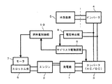
以下に図面を参照して本発明の一実施形態を詳細に説明する。図1はエンジン駆動発電機の構成を示すブロック図である。磁石式多極発電機(以下、単に「発電機」という)には(内燃)エンジン2が連結され、該発電機1はエンジン2で駆動され、多相(代表的には3相)の交流電流を発生する。発生した交流は半導体整流素子としてのサイリスタをブリッジに組んだ整流回路からなるコンバータ3で全波整流されて直流に変換され、インバータ4に入力される。インバータ4は、その出力側に接続された外部負荷5に商用周波数(例えば50Hz)の単相交流を供給する。エンジン2のスロットル弁6の開度調節のためにステッピングモータ7が設けられ、このステッピングモータ7に供給されるパルス数によってスロットル開度が制御され、エンジン2の回転数が決定される。なお、エンジン2は燃料噴射式のものでもよく、その場合はスロットル開度制御に代えて燃料噴射時間制御により回転数を決定する。
【0012】
電圧検出部8はコンバータ3の出力電圧を検出する。サイリスタ駆動回路9は予め与えられた目標としての設定電圧(例えば、170V)と前記出力電圧とを比較し、計測されたコンバータ3の実出力電圧が設定電圧に等しくなるように、公知の適宜の手法で、コンバータ3を構成するサイリスタの導通を制御する。このような構成により、前記サイリスタの導通角制御範囲に相応する出力電流範囲においてはコンバータ3の出力電圧は設定電圧に保持される。
【0013】
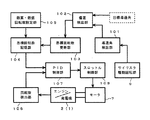
燃料量制御部10は次のように構成される。図2は、燃料量制御部10の構成を示すブロック図である。サイリスタ導通角検出部101は前記サイリスタ駆動回路9からコンバータ3に出力されている制御信号に基づいてサイリスタの導通角を検出する。導通角は予定周期で連続的に検出され、その平均導通角が算出される。平均導通角は予定回(例えば10回分)の連続データを移動平均によって算出するのが好ましい。
【0014】
サイリスタ導通角検出部101で算出された平均導通角は偏差検出部102に入力され、目標導通角に対する偏差が検出される。すなわち、発電機1が出力に余裕のある状態で運転されているかどうかをサイリスタの平均導通角に基づいて判断する。そのために、目標導通角は例えば80%に設定してある。この目標導通角は、一般的な制御目標値と同様、一定のヒステリシスを有するのがよい。なお、目標導通角は固定値であってもよいし、エンジン2の温度に応じて可変としてもよい。例えば、エンジン2の温度が低いときは、目標導通角を小さくする。こうして、偏差検出部102で検出された偏差が「0」になるようにエンジン2が目標回転数に調整され、発電機1に余裕がある状態が維持される。
【0015】
図3は導通角80%で制御されたときのサイリスタの出力電圧波形である。同図において、導通角αはサイリスタが導通している時間に対応する電気角であり、既知の適宜の手段によって決定される。
【0016】
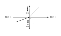
目標回転数更新部103は偏差検出部102から入力される偏差に応じて回転数調整量を出力する。偏差を読み出しアドレスとして回転数調整量を出力するテーブルで構成できる。図4は前記偏差と回転数調整量との関係を示す図である。ここで、偏差は目標導通角に対する実導通角の偏倚量つまり「実導通角−目標導通角」である。同図において、前記偏差がプラスのときは、それがマイナスのときよりも、偏差に対応する回転数調整量が大きく設定されている。偏差がプラスのときは、導通角が目標導通角(80%)を超えている場合であるから発電機1に余裕がないと判断され、負荷に相応する発電機1の出力増加応答を早くする必要があるからであり、偏差がマイナスのときは発電機1に余裕があると判断されるので、過度な応答によるオーバシュートによって起こり得る回転数の頻繁な上下を避けるのが好ましいからである。
【0017】
図2に戻って、目標回転数記憶部104は目標回転数更新部103から入力される目標回転数調整量を、すでに格納されている目標回転数に加算して新たな目標回転数とする。目標回転数は最高・最低回転数設定部105に設定されている最高回転数または最低回転数の範囲内で更新される。前記目標回転数調整量を加算した結果、目標回転数が前記範囲から外れるようなときは、目標回転数は前記最高回転数または前記最低回転数に制限される。最低回転数を規定しているのは、サイリスタ導通角がわずかな回転数変化に反応することで無負荷〜軽負荷での安定性を悪化させないためである。
【0018】
回転数検出部106は発電機1の回転数を検出する。制御量演算部107は前記回転数検出部106から入力される実回転数と前記目標回転数記憶部104から読み込んだ目標回転数とに基づいて、目標回転数に対する実回転数の偏差がゼロにするための制御量を、既知の適宜の手法(例えば比例・積分・微分)によって演算する。スロットル制御部108はステッフピングモータ7を含み、制御量演算部107での演算結果に応じてステッピングモータ7を駆動するためのパルス数を出力し、ステッピングモータ7はこれに応答して回動し、スロットル開度を変化させる。
【0019】
上述のように、本実施形態では、コンバータ3の出力を制御するサイリスタブリッジ整流回路の平均導通角が予め設定された値(例えば80%)に維持されるようにエンジン2の回転数を制御しているので、発電機1は常に余力のある状態で負荷に電力を供給することができる。すなわち、負荷が増大した場合、コンバータ3の出力電圧の変動に応答してサイリスタの導通角を大きくして直ちに負荷の増大に追従できると共に、その導通角の増大に見合ってエンジン2の回転数が比較的緩やかに増大される。エンジン回転数の頻繁な変化を緩和してエンジンの騒音や燃料消費量低減に有利に作用する。
【0020】
本実施形態によれば、インバータの入力側で出力電圧を検出しているので、インバータの出力の有効電力、インバータの変換効率、回転数毎の発電能力、ならびに発電機および有効電力検出部の製品ばらつき等をパラメータとして算出する必要がなくなり、制御が簡単になる。なお、本実施形態では、発電機の出力電流を整流するためにサイリスタブリッジを採用したコンバータを例に説明したが、他の電圧制御方式、例えば整流後のスイッチングDC電圧変換方式であってもよい。
【0021】
【発明の効果】
以上の説明から明らかなように、本発明によれば、発電能力の余力を監視し、余力が維持されるようにエンジンの回転数を制御できるので、発電余力の範囲で負荷の変動に迅速に応答することができる。一方、エンジンの回転数は負荷に応じた適正エンジン負荷となり、エンジンの騒音や燃料消費量の低減が図られる。また、コンバータのサイリスタ(一般的には半導体整流素子)の導通量を予定値に維持するように運転することで前記発電機の余力を簡単に確保することができる。
【図面の簡単な説明】
【図1】本発明の一実施形態に係るエンジン発電機のシステム構成を示すブロック図である。
【図2】エンジン発電機の燃料量制御部の要部構成を示すブロック図である。
【図3】サイリスタの導通角の説明図である。
【図4】導通角偏差と目標回転数調整量との関係を示す図である。
【符号の説明】
1…発電機、 2…エンジン、 3…コンバータ、 4…インバータ、 7…スロットル開度制御用モータ、 8…電圧検出部、 9…サイリスタ駆動回路、10…燃料量制御部、 101…導通角検出部、 102…偏差検出部、 103…目標回転数更新部、 106…回転数検出部、 108…スロットル制御部[0001]
TECHNICAL FIELD OF THE INVENTION
The present invention relates to an engine-driven generator, and more particularly, to an engine-driven generator that controls the number of revolutions of an engine according to the magnitude of a load.
[0002]
[Prior art]
2. Description of the Related Art Many engine-driven generators used as AC power supply devices use an inverter device to stabilize an output frequency. In this type of engine-driven generator, an alternating current is generated by driving an engine connected to the generator, which is once converted into a direct current, and then converted into an alternating current of a commercial frequency by an inverter device and output. In the generator using the inverter device, the output frequency does not depend on the engine speed, so that the output control according to the load can be performed by controlling the engine speed.
[0003]
For example, an inverter-type engine generator described in Japanese Patent Application Laid-Open No. Hei 5-18285 detects a load based on the output current of an inverter device, and performs throttle control of the engine based on the detection result. In this way, the output voltage can be maintained substantially constant regardless of the load fluctuation.
[0004]
[Problems to be solved by the invention]
When the engine speed is controlled to an optimum value according to the load, the engine speed must be controlled so that the load is within the power generation capacity of the generator. However, the optimum rotation speed suitable for the load is based on the active power (voltage × current × power factor) of the output of the inverter device, the conversion efficiency of the inverter device, the power generation capacity for each rotation speed, and the products of the generator and the active power detection unit. It is necessary to calculate a variation or the like as a parameter, which is a very complicated control.
[0005]
On the other hand, there has been proposed an engine generator which detects an output voltage of a generator at an input side of an inverter device and compares the output voltage with a preset reference voltage to obtain an engine speed corresponding to a load. (JP-A-5-146200).
[0006]
However, in any of the above-mentioned engine generators, if the output voltage of the generator decreases due to a load exceeding the capacity corresponding to the engine speed, the target engine speed is increased and the engine speed is increased. However, there is a problem that the engine speed cannot be easily increased.
[0007]
Furthermore, when controlling the throttle opening of the engine based on the deviation of the detected output current or output voltage from the target value, it takes time until the output of the generator changes in response to the change in the throttle opening. Due to the delay, there is also a problem that the output voltage cannot easily follow the fluctuation of the load and becomes unstable.
[0008]
An object of the present invention is to provide an engine-driven generator capable of stably controlling an output voltage by always giving an appropriate surplus to an actual power generation capacity for a wide range of electric loads.
[0009]
[Means for Solving the Problems]
An engine-driven generator according to the present invention includes: a converter including a semiconductor rectifying element for rectifying an output current of a generator driven by an engine; an inverter for converting a DC output from the converter to an AC having a predetermined frequency; goals and semiconductor rectifying element driving circuit for controlling the conduction of the semiconductor rectifier for controlling a target value the output voltage, the conduction amount detecting means for detecting an amount of conduction of the semiconductor rectifying element, a value less than the maximum amount of conduction of a target conduction amount setting means for setting a conduction amount, the amount detected conduction equipped with an engine rotational speed control means for controlling the rotational speed of the engine so as to converge on the target conduction amount in the conduction detecting means There is a feature in the point.
[0010]
Since the conduction amount of the semiconductor rectifier is controlled to the target conduction amount set to be less than the maximum conduction amount , when the load increases, the conduction amount can be increased accordingly. That is, since the generator is always operated with the remaining power, the generator can quickly respond to the increase in the load within the range of the remaining power. Further, it is possible to suppress the fluctuation of the engine rotation from affecting the output voltage.
[0011]
BEST MODE FOR CARRYING OUT THE INVENTION
Hereinafter, an embodiment of the present invention will be described in detail with reference to the drawings. FIG. 1 is a block diagram showing the configuration of the engine-driven generator. An (internal combustion)
[0012]
Voltage detector 8 detects an output voltage of converter 3. The thyristor drive circuit 9 compares a predetermined set voltage (for example, 170 V) as a target given in advance with the output voltage, and sets a known appropriate voltage so that the measured actual output voltage of the converter 3 becomes equal to the set voltage. The conduction of the thyristor constituting the converter 3 is controlled by the technique. With such a configuration, the output voltage of converter 3 is maintained at the set voltage in the output current range corresponding to the conduction angle control range of the thyristor.
[0013]
The fuel
[0014]
The average conduction angle calculated by the thyristor conduction angle detection unit 101 is input to the
[0015]
FIG. 3 shows an output voltage waveform of the thyristor when the conduction angle is controlled at 80%. In the drawing, the conduction angle α is an electrical angle corresponding to the time during which the thyristor is conducting, and is determined by known appropriate means.
[0016]
The target rotation
[0017]
Returning to FIG. 2, the target rotation
[0018]
The rotation
[0019]
As described above, in the present embodiment, the rotation speed of the
[0020]
According to this embodiment, since the output voltage is detected on the input side of the inverter, the active power of the output of the inverter, the conversion efficiency of the inverter, the power generation capacity for each rotation speed, and the products of the generator and the active power detection unit It is not necessary to calculate variations and the like as parameters, and control is simplified. In the present embodiment, a converter employing a thyristor bridge for rectifying the output current of the generator has been described as an example. However, another voltage control method, for example, a rectified switching DC voltage conversion method may be used. .
[0021]
【The invention's effect】
As is apparent from the above description, according to the present invention, the surplus of the power generation capacity can be monitored and the engine speed can be controlled so that the surplus power is maintained. Can respond. On the other hand, the number of revolutions of the engine becomes an appropriate engine load according to the load, and the noise and the fuel consumption of the engine are reduced. In addition, by operating the thyristor (generally a semiconductor rectifier) of the converter so as to maintain the conduction amount at a predetermined value, it is possible to easily secure the remaining power of the generator.
[Brief description of the drawings]
FIG. 1 is a block diagram showing a system configuration of an engine generator according to an embodiment of the present invention.
FIG. 2 is a block diagram showing a main configuration of a fuel amount control unit of the engine generator.
FIG. 3 is an explanatory diagram of a conduction angle of a thyristor.
FIG. 4 is a diagram showing a relationship between a conduction angle deviation and a target rotation speed adjustment amount.
[Explanation of symbols]
DESCRIPTION OF
Claims (5)
前記コンバータから出力される直流を所定周波数の交流に変換するインバータと、
前記エンジンの回転数を制御するエンジン回転数制御手段とを有するエンジン駆動発電機において、
前記半導体整流素子の導通量を検出する導通量検出手段と、
前記半導体整流素子の最大導通量未満の値を目標導通量として設定する目標導通量設定手段と、
前記コンバータの出力電圧を目標値に制御するため前記半導体整流素子の導通量を制御する半導体整流素子駆動回路とを具備し、
前記エンジン回転数制御手段が、前記導通量検出手段で検出された導通量が前記目標導通量に収斂するように前記エンジンの回転数を制御することを特徴とするエンジン駆動発電機。A converter comprising a semiconductor rectifier for rectifying an output current of a generator driven by the engine;
An inverter that converts DC output from the converter into AC having a predetermined frequency;
An engine drive generator having an engine speed control means for controlling the engine speed,
Conduction amount detection means for detecting the conduction amount of the semiconductor rectifier,
Target conduction amount setting means for setting a value less than the maximum conduction amount of the semiconductor rectifier as the target conduction amount,
A semiconductor rectifier drive circuit for controlling the amount of conduction of the semiconductor rectifier to control the output voltage of the converter to a target value,
It said engine speed control means, the amount of conduction engine generator that amount detected conduction and controlling the rotational speed of the engine so as to converge on the target conduction amount by the detection means.
前記エンジン回転数制御手段が、前記偏差を小さくするように前記エンジンの回転数を制御するように構成されたことを特徴とする請求項1記載のエンジン駆動発電機。A deviation detection unit that detects a deviation of the conduction amount detected by the conduction amount detection unit with respect to the target conduction amount,
The engine drive generator according to claim 1, wherein the engine speed control means is configured to control the engine speed so as to reduce the deviation.
前記エンジン回転数制御手段が、前記偏差が負の場合は前記エンジンの回転数を低減させ、前記偏差が正の場合は前記エンジンの回転数を増大させるとともに、前記低減の程度よりも増大の程度を大きくするように構成されたことを特徴とする請求項1記載のエンジン駆動発電機。 A deviation detection unit that detects a value obtained by subtracting a target conduction amount from the conduction amount detected by the conduction amount detection unit as a deviation,
The engine speed control means reduces the engine speed when the deviation is negative, increases the engine speed when the deviation is positive, and increases the engine speed more than the degree of the reduction. The engine-driven generator according to claim 1 , wherein the engine drive generator is configured to increase the value.
Priority Applications (7)
| Application Number | Priority Date | Filing Date | Title |
|---|---|---|---|
| JP12410498A JP3540152B2 (en) | 1998-04-17 | 1998-04-17 | Engine driven generator |
| US09/281,325 US6130486A (en) | 1998-04-17 | 1999-03-30 | Engine operated generator |
| TW088105476A TW434999B (en) | 1998-04-17 | 1999-04-07 | Engine operated generator |
| EP99106165A EP0951136B1 (en) | 1998-04-17 | 1999-04-08 | Engine operated generator |
| DE69902964T DE69902964T2 (en) | 1998-04-17 | 1999-04-08 | Motor driven generator |
| KR1019990012885A KR100320342B1 (en) | 1998-04-17 | 1999-04-13 | Engine operated generator |
| CN99105121A CN1078402C (en) | 1998-04-17 | 1999-04-16 | Electricity generator driven by motor |
Applications Claiming Priority (1)
| Application Number | Priority Date | Filing Date | Title |
|---|---|---|---|
| JP12410498A JP3540152B2 (en) | 1998-04-17 | 1998-04-17 | Engine driven generator |
Publications (2)
| Publication Number | Publication Date |
|---|---|
| JPH11308896A JPH11308896A (en) | 1999-11-05 |
| JP3540152B2 true JP3540152B2 (en) | 2004-07-07 |
Family
ID=14877029
Family Applications (1)
| Application Number | Title | Priority Date | Filing Date |
|---|---|---|---|
| JP12410498A Expired - Fee Related JP3540152B2 (en) | 1998-04-17 | 1998-04-17 | Engine driven generator |
Country Status (7)
| Country | Link |
|---|---|
| US (1) | US6130486A (en) |
| EP (1) | EP0951136B1 (en) |
| JP (1) | JP3540152B2 (en) |
| KR (1) | KR100320342B1 (en) |
| CN (1) | CN1078402C (en) |
| DE (1) | DE69902964T2 (en) |
| TW (1) | TW434999B (en) |
Cited By (1)
| Publication number | Priority date | Publication date | Assignee | Title |
|---|---|---|---|---|
| US7612460B2 (en) | 2006-05-31 | 2009-11-03 | Honda Motor Co., Ltd. | Engine-driven power generator |
Families Citing this family (27)
| Publication number | Priority date | Publication date | Assignee | Title |
|---|---|---|---|---|
| US5994881A (en) * | 1997-10-07 | 1999-11-30 | Hitachi, Ltd. | Control apparatus for a synchronous generator system and a hybrid-type electric vehicle using it |
| US6281664B1 (en) | 1999-01-13 | 2001-08-28 | Honda Giken Kogyo Kabushiki Kaisha | Generator and generator apparatus |
| US6392312B1 (en) * | 1999-10-26 | 2002-05-21 | Gary Jay Morris | Portable electric power generator with remote control and safety apparatus |
| JP3784243B2 (en) | 2000-06-30 | 2006-06-07 | 本田技研工業株式会社 | Engine drive power generator |
| JP3969623B2 (en) | 2000-06-30 | 2007-09-05 | 本田技研工業株式会社 | Engine drive power generator |
| JP2002101560A (en) | 2000-09-26 | 2002-04-05 | Honda Motor Co Ltd | Power generator |
| JP2002204597A (en) | 2001-01-05 | 2002-07-19 | Honda Motor Co Ltd | Inverter-control type generator |
| JP2002204596A (en) * | 2001-01-05 | 2002-07-19 | Honda Motor Co Ltd | Inverter-control type generator |
| JP4072993B2 (en) | 2001-09-04 | 2008-04-09 | 本田技研工業株式会社 | Engine generator |
| JP2003074400A (en) | 2001-09-04 | 2003-03-12 | Honda Motor Co Ltd | Engine speed control device of engine |
| JP2003083136A (en) * | 2001-09-06 | 2003-03-19 | Sawafuji Electric Co Ltd | Engine drive generating device |
| JP2004201480A (en) | 2002-12-20 | 2004-07-15 | Honda Motor Co Ltd | Inverter controlled power generator |
| EP1597806A1 (en) * | 2003-02-20 | 2005-11-23 | Ebara Corporation | Power generating apparatus |
| FR2892574A1 (en) * | 2005-10-20 | 2007-04-27 | Leroy Somer Moteurs | DEVICE FOR CONTROLLING AN ELECTROGEN GROUP |
| CN100444514C (en) * | 2007-02-16 | 2008-12-17 | 吴德峰 | Converse speed regulation apparatus of generator and control method |
| AU2009202713B2 (en) | 2008-07-25 | 2010-09-09 | Honda Motor Co., Ltd. | Inverter generator |
| JP5281329B2 (en) | 2008-07-25 | 2013-09-04 | 本田技研工業株式会社 | Inverter generator |
| JP5130142B2 (en) * | 2008-07-25 | 2013-01-30 | 本田技研工業株式会社 | Inverter generator |
| JP5475267B2 (en) * | 2008-10-28 | 2014-04-16 | ヤンマー株式会社 | Engine generator |
| JP5424611B2 (en) * | 2008-10-28 | 2014-02-26 | 澤藤電機株式会社 | Inverter generator |
| CN101789748B (en) * | 2009-01-19 | 2013-10-23 | 日立工机株式会社 | Electric tool |
| GB2474447B (en) | 2009-10-13 | 2014-12-10 | Mtu Friedrichshafen Gmbh | Generating set preloader |
| JP5745931B2 (en) | 2011-05-17 | 2015-07-08 | 本田技研工業株式会社 | Inverter generator control device |
| CN102857167B (en) * | 2012-09-24 | 2015-06-17 | 三一重机有限公司 | Method for controlling rotational speed of engine generator |
| US10294858B2 (en) | 2013-08-29 | 2019-05-21 | Polaris Industries Inc. | Portable generator |
| KR101695390B1 (en) | 2016-01-18 | 2017-01-23 | 김정희 | Sequential power injection apparatus using dial time relay for reducing the contract power of low voltage consumer |
| WO2018156647A1 (en) * | 2017-02-21 | 2018-08-30 | Dynamo Micropower Corporation | Control of fuel flow for power generation based on dc link level |
Family Cites Families (22)
| Publication number | Priority date | Publication date | Assignee | Title |
|---|---|---|---|---|
| US4119861A (en) * | 1975-10-15 | 1978-10-10 | Tokyo Shibaura Electric Company, Ltd. | Starting apparatus for gas turbine-generator mounted on electric motor driven motorcar |
| US4156896A (en) * | 1978-04-10 | 1979-05-29 | General Electric Company | Method of controlling a power conversion system |
| CN1011869B (en) * | 1989-09-11 | 1991-03-06 | 胡青云 | Heat insulation electrode holder |
| US5229929A (en) * | 1990-11-30 | 1993-07-20 | Honda Giken Kogyo Kabushiki Kaisha | Output peak current correction for PWM invertors |
| JP2587806B2 (en) * | 1990-12-27 | 1997-03-05 | 本田技研工業株式会社 | Portable engine generator |
| JPH0518285A (en) * | 1991-07-05 | 1993-01-26 | Kubota Corp | Inverter type engine generator |
| JPH05146200A (en) * | 1991-11-21 | 1993-06-11 | Sawafuji Electric Co Ltd | Engine generator |
| JP2814863B2 (en) * | 1992-12-07 | 1998-10-27 | 日産自動車株式会社 | Generator control device |
| JPH06257795A (en) * | 1993-03-02 | 1994-09-16 | Matsushita Electric Ind Co Ltd | Front grill for air conditioner outdoor device |
| JP3019682B2 (en) * | 1993-09-17 | 2000-03-13 | トヨタ自動車株式会社 | Power generation control method for hybrid vehicles |
| JP2973796B2 (en) * | 1993-10-07 | 1999-11-08 | トヨタ自動車株式会社 | Air conditioning control method for hybrid electric vehicle |
| JP3178503B2 (en) * | 1994-07-01 | 2001-06-18 | 株式会社デンソー | Hybrid vehicle control device |
| JP3592767B2 (en) * | 1994-11-09 | 2004-11-24 | 三菱電機株式会社 | Engine control device |
| JPH08189385A (en) * | 1995-01-09 | 1996-07-23 | Kokusan Denki Co Ltd | Internal combustion engine driven power generating device |
| JP3248827B2 (en) * | 1995-01-18 | 2002-01-21 | 三菱電機株式会社 | Engine generator control device |
| JPH08251928A (en) * | 1995-03-07 | 1996-09-27 | Toshiba Corp | Converter |
| JPH1052046A (en) * | 1996-08-01 | 1998-02-20 | Honda Motor Co Ltd | Portable power supply unit |
| JP3367829B2 (en) * | 1996-08-01 | 2003-01-20 | 本田技研工業株式会社 | Power supply |
| US5994881A (en) * | 1997-10-07 | 1999-11-30 | Hitachi, Ltd. | Control apparatus for a synchronous generator system and a hybrid-type electric vehicle using it |
| JP3099769B2 (en) * | 1997-03-24 | 2000-10-16 | トヨタ自動車株式会社 | Power output device and control method thereof |
| JP3536581B2 (en) * | 1997-04-16 | 2004-06-14 | 日産自動車株式会社 | Power generation control device for hybrid electric vehicle |
| JP3486326B2 (en) * | 1997-06-23 | 2004-01-13 | トヨタ自動車株式会社 | Operation control method and device for synchronous motor |
-
1998
- 1998-04-17 JP JP12410498A patent/JP3540152B2/en not_active Expired - Fee Related
-
1999
- 1999-03-30 US US09/281,325 patent/US6130486A/en not_active Expired - Lifetime
- 1999-04-07 TW TW088105476A patent/TW434999B/en not_active IP Right Cessation
- 1999-04-08 EP EP99106165A patent/EP0951136B1/en not_active Expired - Lifetime
- 1999-04-08 DE DE69902964T patent/DE69902964T2/en not_active Expired - Lifetime
- 1999-04-13 KR KR1019990012885A patent/KR100320342B1/en not_active IP Right Cessation
- 1999-04-16 CN CN99105121A patent/CN1078402C/en not_active Expired - Fee Related
Cited By (1)
| Publication number | Priority date | Publication date | Assignee | Title |
|---|---|---|---|---|
| US7612460B2 (en) | 2006-05-31 | 2009-11-03 | Honda Motor Co., Ltd. | Engine-driven power generator |
Also Published As
| Publication number | Publication date |
|---|---|
| JPH11308896A (en) | 1999-11-05 |
| KR100320342B1 (en) | 2002-01-10 |
| EP0951136A2 (en) | 1999-10-20 |
| TW434999B (en) | 2001-05-16 |
| CN1233883A (en) | 1999-11-03 |
| DE69902964D1 (en) | 2002-10-24 |
| KR19990083145A (en) | 1999-11-25 |
| DE69902964T2 (en) | 2003-06-05 |
| US6130486A (en) | 2000-10-10 |
| EP0951136B1 (en) | 2002-09-18 |
| EP0951136A3 (en) | 2001-04-18 |
| CN1078402C (en) | 2002-01-23 |
Similar Documents
| Publication | Publication Date | Title |
|---|---|---|
| JP3540152B2 (en) | Engine driven generator | |
| JP3969623B2 (en) | Engine drive power generator | |
| JP3784243B2 (en) | Engine drive power generator | |
| RU2528621C2 (en) | System and method for dynamic control of active power at load | |
| JPH06105563A (en) | Motor driver and air conditioner using the same | |
| JP4072993B2 (en) | Engine generator | |
| JP2001314084A (en) | Power supply apparatus, motor drive apparatus and air conditioner | |
| KR100550650B1 (en) | Inverter control type generator | |
| JP4272276B2 (en) | Power converter for wind power generation and control method thereof | |
| JP2002204596A (en) | Inverter-control type generator | |
| Sousa et al. | Efficiency optimization of a solar boat induction motor drive | |
| JP2004218467A (en) | Engine drive power generating device | |
| JPH0452719B2 (en) | ||
| JPH0415384B2 (en) | ||
| JPH05236795A (en) | Controller and control method for induction motor | |
| JPH06153588A (en) | Electric-power control device for ac induction motor | |
| JPH0652399U (en) | Main shaft drive generator |
Legal Events
| Date | Code | Title | Description |
|---|---|---|---|
| TRDD | Decision of grant or rejection written | ||
| A01 | Written decision to grant a patent or to grant a registration (utility model) |
Free format text: JAPANESE INTERMEDIATE CODE: A01 Effective date: 20040323 |
|
| A61 | First payment of annual fees (during grant procedure) |
Free format text: JAPANESE INTERMEDIATE CODE: A61 Effective date: 20040324 |
|
| R150 | Certificate of patent or registration of utility model |
Free format text: JAPANESE INTERMEDIATE CODE: R150 |
|
| FPAY | Renewal fee payment (event date is renewal date of database) |
Free format text: PAYMENT UNTIL: 20080402 Year of fee payment: 4 |
|
| FPAY | Renewal fee payment (event date is renewal date of database) |
Free format text: PAYMENT UNTIL: 20090402 Year of fee payment: 5 |
|
| FPAY | Renewal fee payment (event date is renewal date of database) |
Free format text: PAYMENT UNTIL: 20090402 Year of fee payment: 5 |
|
| FPAY | Renewal fee payment (event date is renewal date of database) |
Free format text: PAYMENT UNTIL: 20100402 Year of fee payment: 6 |
|
| FPAY | Renewal fee payment (event date is renewal date of database) |
Free format text: PAYMENT UNTIL: 20110402 Year of fee payment: 7 |
|
| FPAY | Renewal fee payment (event date is renewal date of database) |
Free format text: PAYMENT UNTIL: 20110402 Year of fee payment: 7 |
|
| FPAY | Renewal fee payment (event date is renewal date of database) |
Free format text: PAYMENT UNTIL: 20130402 Year of fee payment: 9 |
|
| FPAY | Renewal fee payment (event date is renewal date of database) |
Free format text: PAYMENT UNTIL: 20130402 Year of fee payment: 9 |
|
| FPAY | Renewal fee payment (event date is renewal date of database) |
Free format text: PAYMENT UNTIL: 20140402 Year of fee payment: 10 |
|
| LAPS | Cancellation because of no payment of annual fees |