JP2017008437A - Nonwoven fabric and method for producing the same - Google Patents
Nonwoven fabric and method for producing the same Download PDFInfo
- Publication number
- JP2017008437A JP2017008437A JP2015124040A JP2015124040A JP2017008437A JP 2017008437 A JP2017008437 A JP 2017008437A JP 2015124040 A JP2015124040 A JP 2015124040A JP 2015124040 A JP2015124040 A JP 2015124040A JP 2017008437 A JP2017008437 A JP 2017008437A
- Authority
- JP
- Japan
- Prior art keywords
- nonwoven fabric
- fibrous carbon
- carbon nanostructure
- dispersion
- fiber
- Prior art date
- Legal status (The legal status is an assumption and is not a legal conclusion. Google has not performed a legal analysis and makes no representation as to the accuracy of the status listed.)
- Granted
Links
- 239000004745 nonwoven fabric Substances 0.000 title claims abstract description 142
- 238000004519 manufacturing process Methods 0.000 title claims description 30
- 239000002717 carbon nanostructure Substances 0.000 claims abstract description 136
- 239000000835 fiber Substances 0.000 claims abstract description 110
- 239000006185 dispersion Substances 0.000 claims description 98
- 239000007788 liquid Substances 0.000 claims description 29
- 239000004917 carbon fiber Substances 0.000 claims description 26
- OKTJSMMVPCPJKN-UHFFFAOYSA-N Carbon Chemical compound [C] OKTJSMMVPCPJKN-UHFFFAOYSA-N 0.000 claims description 25
- 239000002041 carbon nanotube Substances 0.000 claims description 23
- 229910021393 carbon nanotube Inorganic materials 0.000 claims description 21
- 229920000049 Carbon (fiber) Polymers 0.000 claims description 20
- 239000002612 dispersion medium Substances 0.000 claims description 19
- 238000002156 mixing Methods 0.000 claims description 14
- VNWKTOKETHGBQD-UHFFFAOYSA-N methane Chemical compound C VNWKTOKETHGBQD-UHFFFAOYSA-N 0.000 claims description 11
- 239000002245 particle Substances 0.000 claims description 8
- 238000000034 method Methods 0.000 description 28
- 238000011282 treatment Methods 0.000 description 16
- 238000002360 preparation method Methods 0.000 description 13
- ZWEHNKRNPOVVGH-UHFFFAOYSA-N 2-Butanone Chemical compound CCC(C)=O ZWEHNKRNPOVVGH-UHFFFAOYSA-N 0.000 description 9
- 238000001035 drying Methods 0.000 description 9
- 238000001914 filtration Methods 0.000 description 9
- 239000000654 additive Substances 0.000 description 8
- 239000000203 mixture Substances 0.000 description 8
- 238000012360 testing method Methods 0.000 description 7
- 239000004372 Polyvinyl alcohol Substances 0.000 description 6
- 230000000996 additive effect Effects 0.000 description 6
- 230000000694 effects Effects 0.000 description 6
- 238000005259 measurement Methods 0.000 description 6
- 229920002451 polyvinyl alcohol Polymers 0.000 description 6
- RTZKZFJDLAIYFH-UHFFFAOYSA-N Diethyl ether Chemical compound CCOCC RTZKZFJDLAIYFH-UHFFFAOYSA-N 0.000 description 5
- 238000009826 distribution Methods 0.000 description 5
- 238000005516 engineering process Methods 0.000 description 5
- 239000000706 filtrate Substances 0.000 description 5
- 229910052751 metal Inorganic materials 0.000 description 5
- 239000002184 metal Substances 0.000 description 5
- 239000000047 product Substances 0.000 description 5
- 229920005989 resin Polymers 0.000 description 5
- 239000011347 resin Substances 0.000 description 5
- 239000000523 sample Substances 0.000 description 5
- 229920002994 synthetic fiber Polymers 0.000 description 5
- 239000012209 synthetic fiber Substances 0.000 description 5
- LFQSCWFLJHTTHZ-UHFFFAOYSA-N Ethanol Chemical compound CCO LFQSCWFLJHTTHZ-UHFFFAOYSA-N 0.000 description 4
- 239000002270 dispersing agent Substances 0.000 description 4
- 238000010130 dispersion processing Methods 0.000 description 4
- 238000009986 fabric formation Methods 0.000 description 4
- 239000002657 fibrous material Substances 0.000 description 4
- -1 polyparaphenylene benzoxazole Polymers 0.000 description 4
- 238000005086 pumping Methods 0.000 description 4
- CSCPPACGZOOCGX-UHFFFAOYSA-N Acetone Chemical compound CC(C)=O CSCPPACGZOOCGX-UHFFFAOYSA-N 0.000 description 3
- XEKOWRVHYACXOJ-UHFFFAOYSA-N Ethyl acetate Chemical compound CCOC(C)=O XEKOWRVHYACXOJ-UHFFFAOYSA-N 0.000 description 3
- OKKJLVBELUTLKV-UHFFFAOYSA-N Methanol Chemical compound OC OKKJLVBELUTLKV-UHFFFAOYSA-N 0.000 description 3
- ZMXDDKWLCZADIW-UHFFFAOYSA-N N,N-Dimethylformamide Chemical compound CN(C)C=O ZMXDDKWLCZADIW-UHFFFAOYSA-N 0.000 description 3
- AMQJEAYHLZJPGS-UHFFFAOYSA-N N-Pentanol Chemical compound CCCCCO AMQJEAYHLZJPGS-UHFFFAOYSA-N 0.000 description 3
- YXFVVABEGXRONW-UHFFFAOYSA-N Toluene Chemical compound CC1=CC=CC=C1 YXFVVABEGXRONW-UHFFFAOYSA-N 0.000 description 3
- 239000001913 cellulose Substances 0.000 description 3
- 229920002678 cellulose Polymers 0.000 description 3
- 150000002009 diols Chemical class 0.000 description 3
- 239000012528 membrane Substances 0.000 description 3
- 239000000843 powder Substances 0.000 description 3
- XLYOFNOQVPJJNP-UHFFFAOYSA-N water Substances O XLYOFNOQVPJJNP-UHFFFAOYSA-N 0.000 description 3
- RFFLAFLAYFXFSW-UHFFFAOYSA-N 1,2-dichlorobenzene Chemical compound ClC1=CC=CC=C1Cl RFFLAFLAYFXFSW-UHFFFAOYSA-N 0.000 description 2
- KBPLFHHGFOOTCA-UHFFFAOYSA-N 1-Octanol Chemical compound CCCCCCCCO KBPLFHHGFOOTCA-UHFFFAOYSA-N 0.000 description 2
- BBMCTIGTTCKYKF-UHFFFAOYSA-N 1-heptanol Chemical compound CCCCCCCO BBMCTIGTTCKYKF-UHFFFAOYSA-N 0.000 description 2
- IJGRMHOSHXDMSA-UHFFFAOYSA-N Atomic nitrogen Chemical compound N#N IJGRMHOSHXDMSA-UHFFFAOYSA-N 0.000 description 2
- 229920002101 Chitin Polymers 0.000 description 2
- 229920001661 Chitosan Polymers 0.000 description 2
- KFZMGEQAYNKOFK-UHFFFAOYSA-N Isopropanol Chemical compound CC(C)O KFZMGEQAYNKOFK-UHFFFAOYSA-N 0.000 description 2
- LRHPLDYGYMQRHN-UHFFFAOYSA-N N-Butanol Chemical compound CCCCO LRHPLDYGYMQRHN-UHFFFAOYSA-N 0.000 description 2
- PXHVJJICTQNCMI-UHFFFAOYSA-N Nickel Chemical compound [Ni] PXHVJJICTQNCMI-UHFFFAOYSA-N 0.000 description 2
- DKGAVHZHDRPRBM-UHFFFAOYSA-N Tert-Butanol Chemical compound CC(C)(C)O DKGAVHZHDRPRBM-UHFFFAOYSA-N 0.000 description 2
- WYURNTSHIVDZCO-UHFFFAOYSA-N Tetrahydrofuran Chemical compound C1CCOC1 WYURNTSHIVDZCO-UHFFFAOYSA-N 0.000 description 2
- ZEASXVYVFFXULL-UHFFFAOYSA-N amezinium metilsulfate Chemical compound COS([O-])(=O)=O.COC1=CC(N)=CN=[N+]1C1=CC=CC=C1 ZEASXVYVFFXULL-UHFFFAOYSA-N 0.000 description 2
- 230000015572 biosynthetic process Effects 0.000 description 2
- 229910052799 carbon Inorganic materials 0.000 description 2
- MVPPADPHJFYWMZ-UHFFFAOYSA-N chlorobenzene Chemical compound ClC1=CC=CC=C1 MVPPADPHJFYWMZ-UHFFFAOYSA-N 0.000 description 2
- 239000011248 coating agent Substances 0.000 description 2
- 238000000576 coating method Methods 0.000 description 2
- 230000000052 comparative effect Effects 0.000 description 2
- JHIVVAPYMSGYDF-UHFFFAOYSA-N cyclohexanone Chemical compound O=C1CCCCC1 JHIVVAPYMSGYDF-UHFFFAOYSA-N 0.000 description 2
- MWKFXSUHUHTGQN-UHFFFAOYSA-N decan-1-ol Chemical compound CCCCCCCCCCO MWKFXSUHUHTGQN-UHFFFAOYSA-N 0.000 description 2
- 239000000428 dust Substances 0.000 description 2
- 239000003822 epoxy resin Substances 0.000 description 2
- 150000002148 esters Chemical class 0.000 description 2
- 239000003365 glass fiber Substances 0.000 description 2
- 230000017525 heat dissipation Effects 0.000 description 2
- ZSIAUFGUXNUGDI-UHFFFAOYSA-N hexan-1-ol Chemical compound CCCCCCO ZSIAUFGUXNUGDI-UHFFFAOYSA-N 0.000 description 2
- ZXEKIIBDNHEJCQ-UHFFFAOYSA-N isobutanol Chemical compound CC(C)CO ZXEKIIBDNHEJCQ-UHFFFAOYSA-N 0.000 description 2
- 239000000463 material Substances 0.000 description 2
- 239000002048 multi walled nanotube Substances 0.000 description 2
- 229920005615 natural polymer Polymers 0.000 description 2
- ZWRUINPWMLAQRD-UHFFFAOYSA-N nonan-1-ol Chemical compound CCCCCCCCCO ZWRUINPWMLAQRD-UHFFFAOYSA-N 0.000 description 2
- 229920003023 plastic Polymers 0.000 description 2
- 239000004033 plastic Substances 0.000 description 2
- 229920002239 polyacrylonitrile Polymers 0.000 description 2
- 229920000647 polyepoxide Polymers 0.000 description 2
- 229920000728 polyester Polymers 0.000 description 2
- 238000011085 pressure filtration Methods 0.000 description 2
- BDERNNFJNOPAEC-UHFFFAOYSA-N propan-1-ol Chemical compound CCCO BDERNNFJNOPAEC-UHFFFAOYSA-N 0.000 description 2
- 239000000126 substance Substances 0.000 description 2
- 239000000758 substrate Substances 0.000 description 2
- 239000004094 surface-active agent Substances 0.000 description 2
- 229920001059 synthetic polymer Polymers 0.000 description 2
- 238000009864 tensile test Methods 0.000 description 2
- KIUKXJAPPMFGSW-DNGZLQJQSA-N (2S,3S,4S,5R,6R)-6-[(2S,3R,4R,5S,6R)-3-Acetamido-2-[(2S,3S,4R,5R,6R)-6-[(2R,3R,4R,5S,6R)-3-acetamido-2,5-dihydroxy-6-(hydroxymethyl)oxan-4-yl]oxy-2-carboxy-4,5-dihydroxyoxan-3-yl]oxy-5-hydroxy-6-(hydroxymethyl)oxan-4-yl]oxy-3,4,5-trihydroxyoxane-2-carboxylic acid Chemical compound CC(=O)N[C@H]1[C@H](O)O[C@H](CO)[C@@H](O)[C@@H]1O[C@H]1[C@H](O)[C@@H](O)[C@H](O[C@H]2[C@@H]([C@@H](O[C@H]3[C@@H]([C@@H](O)[C@H](O)[C@H](O3)C(O)=O)O)[C@H](O)[C@@H](CO)O2)NC(C)=O)[C@@H](C(O)=O)O1 KIUKXJAPPMFGSW-DNGZLQJQSA-N 0.000 description 1
- RYHBNJHYFVUHQT-UHFFFAOYSA-N 1,4-Dioxane Chemical compound C1COCCO1 RYHBNJHYFVUHQT-UHFFFAOYSA-N 0.000 description 1
- OCJBOOLMMGQPQU-UHFFFAOYSA-N 1,4-dichlorobenzene Chemical compound ClC1=CC=C(Cl)C=C1 OCJBOOLMMGQPQU-UHFFFAOYSA-N 0.000 description 1
- JKNCOURZONDCGV-UHFFFAOYSA-N 2-(dimethylamino)ethyl 2-methylprop-2-enoate Chemical compound CN(C)CCOC(=O)C(C)=C JKNCOURZONDCGV-UHFFFAOYSA-N 0.000 description 1
- DPBJAVGHACCNRL-UHFFFAOYSA-N 2-(dimethylamino)ethyl prop-2-enoate Chemical compound CN(C)CCOC(=O)C=C DPBJAVGHACCNRL-UHFFFAOYSA-N 0.000 description 1
- SQDAZGGFXASXDW-UHFFFAOYSA-N 5-bromo-2-(trifluoromethoxy)pyridine Chemical compound FC(F)(F)OC1=CC=C(Br)C=N1 SQDAZGGFXASXDW-UHFFFAOYSA-N 0.000 description 1
- 244000215068 Acacia senegal Species 0.000 description 1
- 229920000178 Acrylic resin Polymers 0.000 description 1
- 239000004925 Acrylic resin Substances 0.000 description 1
- 229920000945 Amylopectin Polymers 0.000 description 1
- 229920000856 Amylose Polymers 0.000 description 1
- 238000004438 BET method Methods 0.000 description 1
- DKPFZGUDAPQIHT-UHFFFAOYSA-N Butyl acetate Natural products CCCCOC(C)=O DKPFZGUDAPQIHT-UHFFFAOYSA-N 0.000 description 1
- ZTQSAGDEMFDKMZ-UHFFFAOYSA-N Butyraldehyde Chemical compound CCCC=O ZTQSAGDEMFDKMZ-UHFFFAOYSA-N 0.000 description 1
- 229920001287 Chondroitin sulfate Polymers 0.000 description 1
- RYGMFSIKBFXOCR-UHFFFAOYSA-N Copper Chemical compound [Cu] RYGMFSIKBFXOCR-UHFFFAOYSA-N 0.000 description 1
- 229920002558 Curdlan Polymers 0.000 description 1
- 239000001879 Curdlan Substances 0.000 description 1
- XDTMQSROBMDMFD-UHFFFAOYSA-N Cyclohexane Chemical compound C1CCCCC1 XDTMQSROBMDMFD-UHFFFAOYSA-N 0.000 description 1
- 229920002307 Dextran Polymers 0.000 description 1
- 229920001353 Dextrin Polymers 0.000 description 1
- 239000004375 Dextrin Substances 0.000 description 1
- 229920000219 Ethylene vinyl alcohol Polymers 0.000 description 1
- YCKRFDGAMUMZLT-UHFFFAOYSA-N Fluorine atom Chemical compound [F] YCKRFDGAMUMZLT-UHFFFAOYSA-N 0.000 description 1
- 229920002907 Guar gum Polymers 0.000 description 1
- 229920000084 Gum arabic Polymers 0.000 description 1
- 229920000877 Melamine resin Polymers 0.000 description 1
- 239000004640 Melamine resin Substances 0.000 description 1
- 239000000020 Nitrocellulose Substances 0.000 description 1
- 239000004677 Nylon Substances 0.000 description 1
- CTQNGGLPUBDAKN-UHFFFAOYSA-N O-Xylene Chemical compound CC1=CC=CC=C1C CTQNGGLPUBDAKN-UHFFFAOYSA-N 0.000 description 1
- 229920000361 Poly(styrene)-block-poly(ethylene glycol) Polymers 0.000 description 1
- 239000002202 Polyethylene glycol Substances 0.000 description 1
- 239000004721 Polyphenylene oxide Substances 0.000 description 1
- 239000004373 Pullulan Substances 0.000 description 1
- 229920001218 Pullulan Polymers 0.000 description 1
- 229920002125 Sokalan® Polymers 0.000 description 1
- 229920002472 Starch Polymers 0.000 description 1
- 229910052769 Ytterbium Inorganic materials 0.000 description 1
- 235000010489 acacia gum Nutrition 0.000 description 1
- 239000000205 acacia gum Substances 0.000 description 1
- DHKHKXVYLBGOIT-UHFFFAOYSA-N acetaldehyde Diethyl Acetal Natural products CCOC(C)OCC DHKHKXVYLBGOIT-UHFFFAOYSA-N 0.000 description 1
- 150000001241 acetals Chemical class 0.000 description 1
- 125000002339 acetoacetyl group Chemical group O=C([*])C([H])([H])C(=O)C([H])([H])[H] 0.000 description 1
- NIXOWILDQLNWCW-UHFFFAOYSA-N acrylic acid group Chemical group C(C=C)(=O)O NIXOWILDQLNWCW-UHFFFAOYSA-N 0.000 description 1
- 238000004220 aggregation Methods 0.000 description 1
- 230000002776 aggregation Effects 0.000 description 1
- 150000001298 alcohols Chemical class 0.000 description 1
- 235000010443 alginic acid Nutrition 0.000 description 1
- 239000000783 alginic acid Substances 0.000 description 1
- 229920000615 alginic acid Polymers 0.000 description 1
- 229960001126 alginic acid Drugs 0.000 description 1
- 150000004781 alginic acids Chemical class 0.000 description 1
- 229920000180 alkyd Polymers 0.000 description 1
- PNEYBMLMFCGWSK-UHFFFAOYSA-N aluminium oxide Inorganic materials [O-2].[O-2].[O-2].[Al+3].[Al+3] PNEYBMLMFCGWSK-UHFFFAOYSA-N 0.000 description 1
- 150000001408 amides Chemical class 0.000 description 1
- 239000004760 aramid Substances 0.000 description 1
- 150000004945 aromatic hydrocarbons Chemical class 0.000 description 1
- 229920003235 aromatic polyamide Polymers 0.000 description 1
- WQZGKKKJIJFFOK-VFUOTHLCSA-N beta-D-glucose Chemical compound OC[C@H]1O[C@@H](O)[C@H](O)[C@@H](O)[C@@H]1O WQZGKKKJIJFFOK-VFUOTHLCSA-N 0.000 description 1
- 230000005540 biological transmission Effects 0.000 description 1
- 235000010418 carrageenan Nutrition 0.000 description 1
- 239000000679 carrageenan Substances 0.000 description 1
- 229920001525 carrageenan Polymers 0.000 description 1
- 229940113118 carrageenan Drugs 0.000 description 1
- 239000003054 catalyst Substances 0.000 description 1
- 238000006243 chemical reaction Methods 0.000 description 1
- 238000005229 chemical vapour deposition Methods 0.000 description 1
- 229940059329 chondroitin sulfate Drugs 0.000 description 1
- 229920006026 co-polymeric resin Polymers 0.000 description 1
- 238000013329 compounding Methods 0.000 description 1
- 150000001875 compounds Chemical class 0.000 description 1
- 230000008602 contraction Effects 0.000 description 1
- 238000001816 cooling Methods 0.000 description 1
- 229910052802 copper Inorganic materials 0.000 description 1
- 239000010949 copper Substances 0.000 description 1
- 235000019316 curdlan Nutrition 0.000 description 1
- 229940078035 curdlan Drugs 0.000 description 1
- 230000007423 decrease Effects 0.000 description 1
- KXGVEGMKQFWNSR-LLQZFEROSA-N deoxycholic acid Chemical compound C([C@H]1CC2)[C@H](O)CC[C@]1(C)[C@@H]1[C@@H]2[C@@H]2CC[C@H]([C@@H](CCC(O)=O)C)[C@@]2(C)[C@@H](O)C1 KXGVEGMKQFWNSR-LLQZFEROSA-N 0.000 description 1
- 229960003964 deoxycholic acid Drugs 0.000 description 1
- 235000019425 dextrin Nutrition 0.000 description 1
- 235000013325 dietary fiber Nutrition 0.000 description 1
- GVGUFUZHNYFZLC-UHFFFAOYSA-N dodecyl benzenesulfonate;sodium Chemical compound [Na].CCCCCCCCCCCCOS(=O)(=O)C1=CC=CC=C1 GVGUFUZHNYFZLC-UHFFFAOYSA-N 0.000 description 1
- 150000002170 ethers Chemical class 0.000 description 1
- 238000011156 evaluation Methods 0.000 description 1
- 239000011737 fluorine Substances 0.000 description 1
- 229910052731 fluorine Inorganic materials 0.000 description 1
- PCHJSUWPFVWCPO-UHFFFAOYSA-N gold Chemical compound [Au] PCHJSUWPFVWCPO-UHFFFAOYSA-N 0.000 description 1
- 229910052737 gold Inorganic materials 0.000 description 1
- 239000010931 gold Substances 0.000 description 1
- 239000010439 graphite Substances 0.000 description 1
- 229910002804 graphite Inorganic materials 0.000 description 1
- 235000010417 guar gum Nutrition 0.000 description 1
- 239000000665 guar gum Substances 0.000 description 1
- 229960002154 guar gum Drugs 0.000 description 1
- FUZZWVXGSFPDMH-UHFFFAOYSA-N hexanoic acid Chemical compound CCCCCC(O)=O FUZZWVXGSFPDMH-UHFFFAOYSA-N 0.000 description 1
- 238000007602 hot air drying Methods 0.000 description 1
- 229920002674 hyaluronan Polymers 0.000 description 1
- 229960003160 hyaluronic acid Drugs 0.000 description 1
- 238000007733 ion plating Methods 0.000 description 1
- 150000002576 ketones Chemical class 0.000 description 1
- 239000002086 nanomaterial Substances 0.000 description 1
- 229910052759 nickel Inorganic materials 0.000 description 1
- 229920001220 nitrocellulos Polymers 0.000 description 1
- 229910052757 nitrogen Inorganic materials 0.000 description 1
- 229920001778 nylon Polymers 0.000 description 1
- 239000005011 phenolic resin Substances 0.000 description 1
- 125000000951 phenoxy group Chemical group [H]C1=C([H])C([H])=C(O*)C([H])=C1[H] 0.000 description 1
- 239000013034 phenoxy resin Substances 0.000 description 1
- 229920006287 phenoxy resin Polymers 0.000 description 1
- XQYMIMUDVJCMLU-UHFFFAOYSA-N phenoxyperoxybenzene Chemical compound C=1C=CC=CC=1OOOC1=CC=CC=C1 XQYMIMUDVJCMLU-UHFFFAOYSA-N 0.000 description 1
- 238000005240 physical vapour deposition Methods 0.000 description 1
- 238000007747 plating Methods 0.000 description 1
- 239000003495 polar organic solvent Substances 0.000 description 1
- 229920000172 poly(styrenesulfonic acid) Polymers 0.000 description 1
- 229920002401 polyacrylamide Polymers 0.000 description 1
- 239000004584 polyacrylic acid Substances 0.000 description 1
- 229920002577 polybenzoxazole Polymers 0.000 description 1
- 239000004417 polycarbonate Substances 0.000 description 1
- 229920000515 polycarbonate Polymers 0.000 description 1
- 229920000570 polyether Polymers 0.000 description 1
- 229920001282 polysaccharide Polymers 0.000 description 1
- 239000005017 polysaccharide Substances 0.000 description 1
- 150000004804 polysaccharides Chemical class 0.000 description 1
- 229940005642 polystyrene sulfonic acid Drugs 0.000 description 1
- 229920000036 polyvinylpyrrolidone Polymers 0.000 description 1
- 235000013855 polyvinylpyrrolidone Nutrition 0.000 description 1
- 239000001267 polyvinylpyrrolidone Substances 0.000 description 1
- 238000003825 pressing Methods 0.000 description 1
- 235000019423 pullulan Nutrition 0.000 description 1
- HNJBEVLQSNELDL-UHFFFAOYSA-N pyrrolidin-2-one Chemical compound O=C1CCCN1 HNJBEVLQSNELDL-UHFFFAOYSA-N 0.000 description 1
- 238000011160 research Methods 0.000 description 1
- 150000003839 salts Chemical class 0.000 description 1
- 238000010008 shearing Methods 0.000 description 1
- 230000035939 shock Effects 0.000 description 1
- SCPYDCQAZCOKTP-UHFFFAOYSA-N silanol Chemical compound [SiH3]O SCPYDCQAZCOKTP-UHFFFAOYSA-N 0.000 description 1
- 229910052709 silver Inorganic materials 0.000 description 1
- 239000004332 silver Substances 0.000 description 1
- 239000002109 single walled nanotube Substances 0.000 description 1
- NRHMKIHPTBHXPF-TUJRSCDTSA-M sodium cholate Chemical compound [Na+].C([C@H]1C[C@H]2O)[C@H](O)CC[C@]1(C)[C@@H]1[C@@H]2[C@@H]2CC[C@H]([C@@H](CCC([O-])=O)C)[C@@]2(C)[C@@H](O)C1 NRHMKIHPTBHXPF-TUJRSCDTSA-M 0.000 description 1
- 229940080264 sodium dodecylbenzenesulfonate Drugs 0.000 description 1
- DAJSVUQLFFJUSX-UHFFFAOYSA-M sodium;dodecane-1-sulfonate Chemical compound [Na+].CCCCCCCCCCCCS([O-])(=O)=O DAJSVUQLFFJUSX-UHFFFAOYSA-M 0.000 description 1
- 239000007787 solid Substances 0.000 description 1
- 239000002904 solvent Substances 0.000 description 1
- 238000001179 sorption measurement Methods 0.000 description 1
- 239000008107 starch Substances 0.000 description 1
- 235000019698 starch Nutrition 0.000 description 1
- YLQBMQCUIZJEEH-UHFFFAOYSA-N tetrahydrofuran Natural products C=1C=COC=1 YLQBMQCUIZJEEH-UHFFFAOYSA-N 0.000 description 1
- 238000001291 vacuum drying Methods 0.000 description 1
- 238000007740 vapor deposition Methods 0.000 description 1
- 229920001285 xanthan gum Polymers 0.000 description 1
- 235000010493 xanthan gum Nutrition 0.000 description 1
- 239000000230 xanthan gum Substances 0.000 description 1
- 229940082509 xanthan gum Drugs 0.000 description 1
- 239000008096 xylene Substances 0.000 description 1
- NAWDYIZEMPQZHO-UHFFFAOYSA-N ytterbium Chemical compound [Yb] NAWDYIZEMPQZHO-UHFFFAOYSA-N 0.000 description 1
- UHVMMEOXYDMDKI-JKYCWFKZSA-L zinc;1-(5-cyanopyridin-2-yl)-3-[(1s,2s)-2-(6-fluoro-2-hydroxy-3-propanoylphenyl)cyclopropyl]urea;diacetate Chemical compound [Zn+2].CC([O-])=O.CC([O-])=O.CCC(=O)C1=CC=C(F)C([C@H]2[C@H](C2)NC(=O)NC=2N=CC(=CC=2)C#N)=C1O UHVMMEOXYDMDKI-JKYCWFKZSA-L 0.000 description 1
Abstract
Description
本発明は、不織布およびその製造方法に関するものである。 The present invention relates to a nonwoven fabric and a method for producing the same.
近年、軽量であるとともに、導電性、熱伝導性および機械的特性に優れる材料として、カーボンナノチューブ(以下、「CNT」と称することがある。)が注目されている。しかし、CNT等の繊維状炭素ナノ構造体は直径がナノメートルサイズの微細な構造体であるため、単体では取り扱い性や加工性が悪い。そこで、例えば、複数本のCNTを用いて不織布を形成し、当該不織布を放熱シートや導電膜などとして用いることが提案されている。具体的には、例えば特許文献1では、溶媒とCNTとを含むカーボンナノチューブ分散液をろ過および乾燥して得たシートを加圧プレスすることにより成膜した不織布を、太陽電池やタッチパネルなどの電極を構成する部材(例えば、導電膜や触媒層など)として用いることが提案されている。 In recent years, carbon nanotubes (hereinafter sometimes referred to as “CNT”) have attracted attention as materials that are lightweight and have excellent conductivity, thermal conductivity, and mechanical properties. However, since a fibrous carbon nanostructure such as CNT is a fine structure having a diameter of nanometers, handling and workability are poor by itself. Therefore, for example, it has been proposed to form a non-woven fabric using a plurality of CNTs, and to use the non-woven fabric as a heat dissipation sheet, a conductive film, or the like. Specifically, for example, in Patent Document 1, a nonwoven fabric formed by press-pressing a sheet obtained by filtering and drying a carbon nanotube dispersion containing a solvent and CNTs is used as an electrode such as a solar cell or a touch panel. It has been proposed to be used as a member (for example, a conductive film or a catalyst layer) that constitutes.
ところで、CNT等の繊維状炭素ナノ構造体の製造には高度な技術および高い製造コストが必要である。特に、BET比表面積が大きい繊維状炭素ナノ構造体は、製造コストが高かった。一方、BET比表面積の小さい繊維状炭素ナノ構造体は、比較的低コストで製造可能なことが知られている。そのため、製造コストの観点からは、放熱シートや導電膜などのシート状部材として用いられる不織布として、BET比表面積の小さい繊維状炭素ナノ構造体を使用して形成したものが注目されている。 By the way, manufacture of fibrous carbon nanostructures, such as CNT, requires advanced technology and high manufacturing cost. In particular, the fibrous carbon nanostructure having a large BET specific surface area has a high production cost. On the other hand, it is known that a fibrous carbon nanostructure having a small BET specific surface area can be produced at a relatively low cost. Therefore, from the viewpoint of manufacturing cost, attention has been paid to those formed using a fibrous carbon nanostructure having a small BET specific surface area as a nonwoven fabric used as a sheet-like member such as a heat dissipation sheet or a conductive film.
しかし、本発明者がBET比表面積の小さい繊維状炭素ナノ構造体を使用した不織布の形成について鋭意研究を行ったところ、BET比表面積が600m2/g以下の繊維状炭素ナノ構造体は互いに絡み合い難く、BET比表面積が600m2/g以下の繊維状炭素ナノ構造体のみを用いた不織布は形成し難い(即ち、成膜性が低い)ことが明らかとなった。特に、BET比表面積が600m2/g以下の繊維状炭素ナノ構造体を含む分散液をろ過および乾燥して得た不織布は、成膜性が低く、プレス処理等の後処理を施さなければ自立性を有するシート状部材として使用し難いことが明らかとなった。 However, when the present inventor conducted intensive research on the formation of a nonwoven fabric using a fibrous carbon nanostructure having a small BET specific surface area, the fibrous carbon nanostructures having a BET specific surface area of 600 m 2 / g or less are entangled with each other. It was difficult to form a non-woven fabric using only the fibrous carbon nanostructure having a BET specific surface area of 600 m 2 / g or less (that is, the film forming property was low). In particular, a nonwoven fabric obtained by filtering and drying a dispersion containing fibrous carbon nanostructures having a BET specific surface area of 600 m 2 / g or less has low film formability and is self-supporting unless post-treatment such as press treatment is performed. It became clear that it was difficult to use as a sheet-like member having the property.
そこで、本発明は、シート状部材として好適に使用可能な、BET比表面積の小さい繊維状炭素ナノ構造体を用いて製造した不織布及びその製造方法を提供することを目的とする。 Then, an object of this invention is to provide the nonwoven fabric manufactured using the fibrous carbon nanostructure with a small BET specific surface area which can be used conveniently as a sheet-like member, and its manufacturing method.
即ち、この発明は、上記課題を有利に解決することを目的とするものであり、本発明の不織布は、BET比表面積が600m2/g以下の繊維状炭素ナノ構造体と、繊維とを含むことを特徴とする。このような不織布は、BET比表面積が600m2/g以下の繊維状炭素ナノ構造体を使用しているので、製造コストが低い。また、BET比表面積が600m2/g以下の繊維状炭素ナノ構造体に加えて繊維も含む不織布は、良好に形成することができ、成膜性にも優れている。ここで、本発明において、BET比表面積が600m2/g以下の繊維状炭素ナノ構造体を「低BET比表面積繊維状炭素ナノ構造体」と称する。
なお、本発明において、「BET比表面積」とは、BET法を用いて測定した窒素吸着比表面積を指す。
また、本発明において、「繊維状炭素ナノ構造体」とは、外径(繊維径)が1μm未満の繊維状の炭素構造体を指す。また、本発明において、「繊維」とは、繊維径が1μm以上の繊維状物質を指し、「繊維」には「繊維状炭素ナノ構造体」は含まれない。
That is, this invention aims at solving the said subject advantageously, The nonwoven fabric of this invention contains the fibrous carbon nanostructure whose BET specific surface area is 600 m < 2 > / g or less, and a fiber. It is characterized by that. Since such a nonwoven fabric uses a fibrous carbon nanostructure having a BET specific surface area of 600 m 2 / g or less, the manufacturing cost is low. Moreover, the nonwoven fabric which also contains a fiber in addition to the fibrous carbon nanostructure whose BET specific surface area is 600 m < 2 > / g or less can be formed favorably, and is excellent in film forming property. Here, in the present invention, a fibrous carbon nanostructure having a BET specific surface area of 600 m 2 / g or less is referred to as a “low BET specific surface area fibrous carbon nanostructure”.
In the present invention, the “BET specific surface area” refers to a nitrogen adsorption specific surface area measured using the BET method.
In the present invention, the “fibrous carbon nanostructure” refers to a fibrous carbon structure having an outer diameter (fiber diameter) of less than 1 μm. In the present invention, “fiber” refers to a fibrous material having a fiber diameter of 1 μm or more, and “fiber” does not include “fibrous carbon nanostructure”.
本発明の不織布では、前記繊維状炭素ナノ構造体100質量部に対して、前記繊維を5質量部以上4000質量部以下の割合で含むことが好ましい。このような比率で繊維状炭素ナノ構造体と繊維とを配合することで、不織布の強度を向上させることができる。 In the nonwoven fabric of this invention, it is preferable to contain the said fiber in the ratio of 5 mass parts or more and 4000 mass parts or less with respect to 100 mass parts of the said fibrous carbon nanostructure. By mix | blending fibrous carbon nanostructure and a fiber in such a ratio, the intensity | strength of a nonwoven fabric can be improved.
また、本発明の不織布では、前記繊維の平均繊維長が、50μm以上であることが好ましい。不織布に含有される繊維の平均繊維長が、50μm以上であれば、不織布の強度を向上させることができる。
なお、本発明において、繊維の平均繊維長は、走査型電子顕微鏡を用いて無作為に選択した繊維100本の繊維長を測定して求めることができる。
Moreover, in the nonwoven fabric of this invention, it is preferable that the average fiber length of the said fiber is 50 micrometers or more. If the average fiber length of the fibers contained in the nonwoven fabric is 50 μm or more, the strength of the nonwoven fabric can be improved.
In the present invention, the average fiber length of the fibers can be determined by measuring the fiber length of 100 fibers randomly selected using a scanning electron microscope.
また、本発明の不織布では、前記繊維の平均繊維径が、3μm以上50μm以下であることが好ましい。不織布に含有される繊維の平均繊維径がかかる範囲内であれば、不織布の強度を向上させることができる。
なお、本発明において、繊維の平均繊維径は、走査型電子顕微鏡を用いて無作為に選択した繊維100本の繊維径を測定して求めることができる。
Moreover, in the nonwoven fabric of this invention, it is preferable that the average fiber diameters of the said fiber are 3 micrometers or more and 50 micrometers or less. If the average fiber diameter of the fiber contained in the nonwoven fabric is within such a range, the strength of the nonwoven fabric can be improved.
In addition, in this invention, the average fiber diameter of a fiber can be calculated | required by measuring the fiber diameter of 100 fibers selected at random using a scanning electron microscope.
本発明の不織布では、前記繊維状炭素ナノ構造体がカーボンナノチューブを含むことが好ましい。繊維状炭素ナノ構造体としてカーボンナノチューブを配合することで、不織布の強度及び導電性を向上させることができる。 In the nonwoven fabric of this invention, it is preferable that the said fibrous carbon nanostructure contains a carbon nanotube. By mix | blending a carbon nanotube as a fibrous carbon nanostructure, the intensity | strength and electroconductivity of a nonwoven fabric can be improved.
本発明の不織布では、前記繊維が炭素繊維を含むことが好ましい。繊維として炭素繊維を配合することで、不織布の導電性を向上させることができる。 In the nonwoven fabric of this invention, it is preferable that the said fiber contains a carbon fiber. By blending carbon fibers as the fibers, the conductivity of the nonwoven fabric can be improved.
また、上記課題を有利に解決する本発明の不織布製造方法は、BET比表面積が600m2/g以下の繊維状炭素ナノ構造体と、繊維と、分散媒とを含む分散液から前記分散媒を除去して不織布を形成する工程を含むことを特徴とする。かかる不織布製造方法によれば、低コストで不織布を製造することができる。また、不織布を良好に形成することができる。 Moreover, the nonwoven fabric manufacturing method of the present invention that advantageously solves the above-mentioned problems is obtained by removing the dispersion medium from a dispersion liquid containing a fibrous carbon nanostructure having a BET specific surface area of 600 m 2 / g or less, fibers, and a dispersion medium. It includes a step of forming a nonwoven fabric by removing. According to this nonwoven fabric manufacturing method, a nonwoven fabric can be manufactured at low cost. Moreover, a nonwoven fabric can be formed favorably.
また、本発明にかかる不織布製造方法は、前記分散媒中に前記繊維状炭素ナノ構造体を添加してなる粗分散液を60MPa以上200MPa以下の圧力で細管流路へと圧送し、前記粗分散液にせん断力を与えて平均粒子径が60μm以下の繊維状炭素ナノ構造体分散液を得た後、前記繊維状炭素ナノ構造体分散液に前記繊維を混合して前記分散液を調製する工程を更に含むことが好ましい。このような工程を実施することで、不織布の強度を向上させることができる。
なお、本発明において、繊維状炭素ナノ構造体分散液の「平均粒子径」とは、繊維状炭素ナノ構造体分散液中に含まれている固形物のメジアン径(体積換算値)を指し、粒度分布計を用いて測定することができる。
Further, in the nonwoven fabric production method according to the present invention, the coarse dispersion obtained by adding the fibrous carbon nanostructure to the dispersion medium is pumped to a capillary channel at a pressure of 60 MPa to 200 MPa, and the coarse dispersion A step of applying a shearing force to the liquid to obtain a fibrous carbon nanostructure dispersion liquid having an average particle size of 60 μm or less, and then mixing the fibers with the fibrous carbon nanostructure dispersion liquid to prepare the dispersion liquid. It is preferable that it is further included. By carrying out such a process, the strength of the nonwoven fabric can be improved.
In the present invention, the “average particle diameter” of the fibrous carbon nanostructure dispersion refers to the median diameter (volume conversion value) of the solid contained in the fibrous carbon nanostructure dispersion, It can be measured using a particle size distribution meter.
本発明によれば、シート状部材として好適に使用可能な、低BET比表面積繊維状炭素ナノ構造体を含有してなる不織布を提供することができる。 ADVANTAGE OF THE INVENTION According to this invention, the nonwoven fabric formed by using the low BET specific surface area fibrous carbon nanostructure which can be used conveniently as a sheet-like member can be provided.
以下、本発明の実施形態について詳細に説明する。
ここで、本発明の不織布は、BET比表面積が600m2/g以下である繊維状炭素ナノ構造体と、繊維とを含む。本発明の不織布は、本発明の不織布製造方法を用いて製造することができる。
Hereinafter, embodiments of the present invention will be described in detail.
Here, the nonwoven fabric of this invention contains the fibrous carbon nanostructure whose BET specific surface area is 600 m < 2 > / g or less, and a fiber. The nonwoven fabric of this invention can be manufactured using the nonwoven fabric manufacturing method of this invention.
(不織布)
本発明の不織布は、通常、複数本の繊維状炭素ナノ構造体と、複数本の繊維とをシート状に集合させて形成した不織布である。なお、不織布には、繊維状炭素ナノ構造体および繊維以外に、不織布の製造時に使用した添加物等のその他の成分が含まれていてもよい。
そして、本発明の不織布は、集合体を構成する繊維状炭素ナノ構造体が、BET比表面積が600m2/g以下と、低BET比表面積であることを大きな特徴の一つとする。なお、本発明の不織布は、支持体が存在していなくとも膜としての形状を保つことができる自立膜である。
ここで、一般に、BET比表面積が小さい繊維状炭素ナノ構造体は、BET比表面積が大きい繊維状炭素ナノ構造体と比較して安価で製造することはできるものの、互いに絡み合い難く、BET比表面積が小さい繊維状炭素ナノ構造体のみでは自立性に優れる不織布を形成し難いと考えられている。しかし驚くべきことに、本発明者は、低BET比表面積繊維状炭素ナノ構造体に対して繊維を配合することで、低BET比表面積繊維状炭素ナノ構造体を用いた膜(不織布)を良好に形成できることを見出し、本発明を完成させた。
(Nonwoven fabric)
The nonwoven fabric of the present invention is usually a nonwoven fabric formed by assembling a plurality of fibrous carbon nanostructures and a plurality of fibers into a sheet shape. In addition to the fibrous carbon nanostructure and fiber, the nonwoven fabric may contain other components such as additives used during the production of the nonwoven fabric.
And the nonwoven fabric of this invention makes it one of the big characteristics that the fibrous carbon nanostructure which comprises an aggregate | assembly has a BET specific surface area of 600 m < 2 > / g or less and a low BET specific surface area. In addition, the nonwoven fabric of this invention is a self-supporting film | membrane which can maintain the shape as a film | membrane, even if a support body does not exist.
Here, in general, a fibrous carbon nanostructure having a small BET specific surface area can be manufactured at a lower cost than a fibrous carbon nanostructure having a large BET specific surface area, but is not easily entangled with each other, and the BET specific surface area is small. It is thought that it is difficult to form a nonwoven fabric excellent in self-supporting property only with a small fibrous carbon nanostructure. Surprisingly, however, the present inventor obtained a good membrane (nonwoven fabric) using the low BET specific surface area fibrous carbon nanostructure by blending the fiber with the low BET specific surface area fibrous carbon nanostructure. The present invention was completed.
<繊維状炭素ナノ構造体>
本発明に用いる繊維状炭素ナノ構造体は、BET比表面積が600m2/g以下であるが、400m2/g以下であることが好ましく、さらに、100m2/g以上であることが好ましく、150m2/g以上であることが更に好ましい。繊維状炭素ナノ構造体のBET比表面積を600m2/g以下とすることで、不織布の製造コストを低くすることができる。また、繊維状炭素ナノ構造体のBET比表面積を100m2/g以上とすることで、成膜性を向上させることができる。
<Fibrous carbon nanostructure>
The fibrous carbon nanostructure used in the present invention has a BET specific surface area of 600 m 2 / g or less, preferably 400 m 2 / g or less, more preferably 100 m 2 / g or more, and 150 m More preferably, it is 2 / g or more. The manufacturing cost of a nonwoven fabric can be made low by making the BET specific surface area of a fibrous carbon nanostructure into 600 m < 2 > / g or less. Moreover, the film formability can be improved by setting the BET specific surface area of the fibrous carbon nanostructure to 100 m 2 / g or more.
さらに、BET比表面積が600m2/g以下の繊維状炭素ナノ構造体は、カーボンナノチューブ(CNT)を含むことが好ましい。繊維状炭素ナノ構造体としてCNTを配合することで、本発明の不織布の強度及び導電性を向上させることができる。BET比表面積が600m2/g以下の繊維状炭素ナノ構造体に含まれるCNTとしては、特に限定されることなく、単層カーボンナノチューブおよび/または多層カーボンナノチューブが挙げられる。さらに、好ましくはBET比表面積が600m2/g以下の繊維状炭素ナノ構造体は、多層カーボンナノチューブである。 Furthermore, the fibrous carbon nanostructure having a BET specific surface area of 600 m 2 / g or less preferably includes carbon nanotubes (CNT). By mix | blending CNT as a fibrous carbon nanostructure, the intensity | strength and electroconductivity of the nonwoven fabric of this invention can be improved. The CNT contained in the fibrous carbon nanostructure having a BET specific surface area of 600 m 2 / g or less is not particularly limited, and examples thereof include single-walled carbon nanotubes and / or multi-walled carbon nanotubes. Further, the fibrous carbon nanostructure preferably having a BET specific surface area of 600 m 2 / g or less is a multi-walled carbon nanotube.
ここで、BET比表面積が600m2/g以下の繊維状炭素ナノ構造体は、円筒形状の炭素ナノ構造体であるCNTのみからなるものであってもよいし、CNTと、CNT以外の非円筒形状の繊維状炭素ナノ構造体との混合物であってもよい。なおかかる非円筒形状の繊維状炭素ナノ構造体は、炭素の六員環ネットワークが扁平筒状に形成されてなる炭素ナノ構造体等の非円筒形状の炭素ナノ構造体である。 Here, the fibrous carbon nanostructure having a BET specific surface area of 600 m 2 / g or less may be composed of only CNT that is a cylindrical carbon nanostructure, or CNT and a non-cylinder other than CNT. It may be a mixture with a fibrous carbon nanostructure having a shape. The non-cylindrical fibrous carbon nanostructure is a non-cylindrical carbon nanostructure such as a carbon nanostructure in which a carbon six-membered ring network is formed in a flat cylindrical shape.
更に、繊維状炭素ナノ構造体の平均直径(Av)は、0.5nm以上であることが好ましく、1nm以上であることがより好ましく、3nm以上であることが更に好ましく、50nm以下であることが好ましく、40nm以下であることがより好ましく、30nm以下であることが更に好ましい。繊維状炭素ナノ構造体の平均直径(Av)が0.5nm以上であれば、繊維状炭素ナノ構造体の凝集を抑制して繊維状炭素ナノ構造体の分散性を高めることができる。また、繊維状炭素ナノ構造体の平均直径(Av)が50nm以下であれば、不織布の強度を十分に高めることができる。
なお、本発明において、繊維状炭素ナノ構造体の平均直径は、透過型電子顕微鏡を用いて無作為に選択した繊維状炭素ナノ構造体100本の直径(外径)を測定して求めることができる。また、繊維状炭素ナノ構造体の平均直径は、繊維状炭素ナノ構造体の製造方法や製造条件を変更することにより調整してもよいし、異なる製法で得られた繊維状炭素ナノ構造体を複数種類組み合わせることにより調整してもよい。
Furthermore, the average diameter (Av) of the fibrous carbon nanostructure is preferably 0.5 nm or more, more preferably 1 nm or more, further preferably 3 nm or more, and preferably 50 nm or less. Preferably, it is 40 nm or less, more preferably 30 nm or less. When the average diameter (Av) of the fibrous carbon nanostructure is 0.5 nm or more, aggregation of the fibrous carbon nanostructure can be suppressed and the dispersibility of the fibrous carbon nanostructure can be enhanced. Moreover, if the average diameter (Av) of fibrous carbon nanostructure is 50 nm or less, the intensity | strength of a nonwoven fabric can fully be raised.
In the present invention, the average diameter of fibrous carbon nanostructures can be determined by measuring the diameter (outer diameter) of 100 fibrous carbon nanostructures selected at random using a transmission electron microscope. it can. Moreover, the average diameter of the fibrous carbon nanostructure may be adjusted by changing the production method and production conditions of the fibrous carbon nanostructure, or the fibrous carbon nanostructure obtained by a different production method may be used. You may adjust by combining multiple types.
また、繊維状炭素ナノ構造体として、構造体の平均長さが100μm以下であるものも使用することができる。 In addition, a fibrous carbon nanostructure having an average structure length of 100 μm or less can be used.
<繊維>
本発明に用いる繊維は、上述したBET比表面積が600m2/g以下の繊維状炭素ナノ構造体とは異なる。そのような繊維は、特に限定されることなく、例えば、ナイロン、ポリエステル、アクリル、アラミド、及びポリパラフェニレンベンズオキサゾールなどの合成繊維、セルロース、キチン、及びキトサンなどの不溶性食物繊維、ガラス繊維、並びに炭素繊維であり得る。好ましくは、本発明の不織布は炭素繊維を含有する。不織布に炭素繊維を含有させることで、不織布の導電性を向上させることができる。
なお、一般に、炭素繊維は、カーボンナノチューブなどの繊維状炭素ナノ構造体よりも導電性が低いと考えられている。しかし、繊維状炭素ナノ構造体と炭素繊維とを用いて形成した不織布は、驚くべきことに、繊維状炭素ナノ構造体と、当該繊維状炭素ナノ構造体よりも導電性の低い炭素繊維とを用いた場合であっても、繊維状炭素ナノ構造体のみを用いて形成した不織布よりも優れた導電性を発揮することができる。この理由は、明らかではないが、繊維状炭素ナノ構造体と炭素繊維とが良好に絡み合うことで不織布内に導電パスが良好に形成されるためであると推察される。
<Fiber>
The fiber used in the present invention is different from the above-described fibrous carbon nanostructure having a BET specific surface area of 600 m 2 / g or less. Such fibers are not particularly limited, for example, synthetic fibers such as nylon, polyester, acrylic, aramid, and polyparaphenylene benzoxazole, insoluble dietary fibers such as cellulose, chitin, and chitosan, glass fibers, and It can be carbon fiber. Preferably, the nonwoven fabric of the present invention contains carbon fibers. By containing carbon fibers in the nonwoven fabric, the conductivity of the nonwoven fabric can be improved.
In general, carbon fibers are considered to have lower conductivity than fibrous carbon nanostructures such as carbon nanotubes. However, a nonwoven fabric formed using fibrous carbon nanostructures and carbon fibers is surprisingly composed of fibrous carbon nanostructures and carbon fibers having lower conductivity than the fibrous carbon nanostructures. Even when it is used, it is possible to exhibit conductivity superior to a nonwoven fabric formed using only fibrous carbon nanostructures. The reason for this is not clear, but it is presumed that the conductive carbon nanostructure and the carbon fiber are intertwined well so that a conductive path is well formed in the nonwoven fabric.
ここで、本発明に用いうる炭素繊維としては、例えば、PAN(Polyacrylonitrile)系、ピッチ(PITCH)系からつくられた炭素繊維や黒鉛繊維が挙げられる。さらに、本発明に用いうる繊維として、炭素繊維、樹脂繊維およびガラス繊維等の繊維状材料の表面を金属で被覆してなる金属被覆繊維も用いることができる。なお、繊維状材料の表面を被覆する金属としては、例えば、ニッケル、イッテルビウム、金、銀、銅などが挙げられる。また、繊維状材料の表面に金属を被覆する方法としては、例えば、メッキ法、CVD法、PVD法、イオンプレーティング法、蒸着法などを用いることができる。特に、繊維としてピッチ系炭素繊維を用いることが好ましい。繊維としてピッチ系炭素繊維を配合することで、不織布の導電率を向上させることができるからである。
これらの繊維は、1種単独で使用してもよいし、2種以上を併用してもよい。
Here, as carbon fiber which can be used for this invention, the carbon fiber and graphite fiber which were made from the PAN (Polyacrylonitrile) type | system | group and the pitch (PITCH) type | system | group are mentioned, for example. Furthermore, as a fiber that can be used in the present invention, a metal-coated fiber formed by coating the surface of a fibrous material such as carbon fiber, resin fiber, and glass fiber with a metal can also be used. In addition, as a metal which coat | covers the surface of a fibrous material, nickel, ytterbium, gold | metal | money, silver, copper etc. are mentioned, for example. Moreover, as a method for coating the surface of the fibrous material with metal, for example, a plating method, a CVD method, a PVD method, an ion plating method, a vapor deposition method, or the like can be used. In particular, it is preferable to use pitch-based carbon fibers as the fibers. It is because the electrical conductivity of a nonwoven fabric can be improved by mix | blending pitch-type carbon fiber as a fiber.
These fibers may be used alone or in combination of two or more.
本発明の不織布では、繊維状炭素ナノ構造体100質量部に対して、繊維を5質量部以上配合することが好ましく、10質量部以上配合することがより好ましく、4000質量部以下配合することが好ましく、1200質量部以下配合することがより好ましく、800質量部以下配合することが更に好ましい。繊維の添加量を上記下限値以上とすることによって、不織布の成膜性を一層向上させることができる。また、繊維の添加量を上記上限値以下とすることによって、不織布の耐粉落ち性を一層向上させることができる。 In the nonwoven fabric of this invention, it is preferable to mix | blend 5 mass parts or more with respect to 100 mass parts of fibrous carbon nanostructures, It is more preferable to mix | blend 10 mass parts or more, It is compounding 4000 mass parts or less. Preferably, it is more preferably 1200 parts by mass or less, and still more preferably 800 parts by mass or less. By making the addition amount of the fiber more than the above lower limit value, the film formability of the nonwoven fabric can be further improved. Moreover, the powder-proof property of a nonwoven fabric can further be improved by making the addition amount of a fiber below the said upper limit.
特に、本発明の不織布では、繊維状炭素ナノ構造体100質量部に対して、繊維を25質量部以上配合することが更に好ましく、50質量部以上配合することが特に好ましく、400質量部以下配合することが特に好ましく、200質量部以下配合することが更に特に好ましい。上記特定範囲の割合で低BET比表面積の繊維状炭素ナノ構造体と繊維とを配合することで、不織布の強度が特に向上するからである。
なお、下記の表1に示す参考例からも明らかなように、本発明者の研究によれば、BET比表面積が600m2/g超である高BET比表面積繊維状炭素ナノ構造体(下記の参考例ではBET比表面積が812m2/gのカーボンナノチューブを使用)は、互いに良好に絡み合って強固な不織布を形成することが可能であるため、繊維を併用することなく高BET比表面積繊維状炭素ナノ構造体のみを用いて不織布を形成した方が高強度の不織布が得られる。そのため、高BET比表面積繊維状炭素ナノ構造体を使用した不織布では、繊維の配合量が増えるほど強度が低下する。しかし、驚くべきことに、BET比表面積が600m2/g以下の繊維状炭素ナノ構造体を使用した不織布においては、繊維を所定の割合で併用した方が、不織布の強度を向上させることができる。
In particular, in the nonwoven fabric of the present invention, it is more preferable to mix 25 parts by mass or more of fibers with respect to 100 parts by mass of the fibrous carbon nanostructure, particularly preferable to mix 50 parts by mass or more, and 400 parts by mass or less. It is particularly preferable to add 200 parts by mass or less. This is because the strength of the nonwoven fabric is particularly improved by blending the fibrous carbon nanostructures and fibers having a low BET specific surface area at a ratio in the specific range.
As is clear from the reference examples shown in Table 1 below, according to the study of the present inventors, a high BET specific surface area fibrous carbon nanostructure having a BET specific surface area of more than 600 m 2 / g (described below) In the reference example, carbon nanotubes having a BET specific surface area of 812 m 2 / g) can be entangled well with each other to form a strong nonwoven fabric, so that a high BET specific surface area fibrous carbon can be used without using fibers. A non-woven fabric having high strength can be obtained by forming a non-woven fabric using only nanostructures. Therefore, in a nonwoven fabric using a high BET specific surface area fibrous carbon nanostructure, the strength decreases as the amount of fibers increases. However, surprisingly, in a nonwoven fabric using a fibrous carbon nanostructure having a BET specific surface area of 600 m 2 / g or less, the strength of the nonwoven fabric can be improved by using fibers in a predetermined ratio. .
*2 ピッチ系炭素繊維(三菱樹脂株式会社製、ダイアリード(登録商標)K223HM)であり、平均繊維径は10μm、平均繊維長は200μmであった。
*3 各不織布を4×2cmに切り抜いたものを試験体とした。小型卓上引張試験機(日本電産シンポ社製、型番「FGS-TV」)を用いて、試験体1cmをチャックでつかみ、30mm/分の引っ張り速度にて引張試験を行い、試験体が破断した際の荷重(N)を厚み(mm)で割った値を評価した。
* 2 A pitch-based carbon fiber (Dialead (registered trademark) K223HM, manufactured by Mitsubishi Plastics, Inc.) having an average fiber diameter of 10 μm and an average fiber length of 200 μm.
* 3 Each non-woven fabric cut out to 4 × 2 cm was used as a test specimen. Using a small tabletop tensile tester (manufactured by Nidec Sympo, model number “FGS-TV”), 1 cm of the test specimen was grasped with a chuck, a tensile test was performed at a pulling speed of 30 mm / min, and the test specimen was broken. A value obtained by dividing the load (N) by the thickness (mm) was evaluated.
また、繊維の平均繊維長は、50μm以上であることが好ましく、100μm以上であることがより好ましい。このような長さを有する繊維を均一に不織布中で分散させることにより、繊維を骨組みのように作用させることができ、成膜性及び強度を向上させることができると推察される。なお、繊維の平均長さは、通常、1000μm以下である。
なお、本発明において、繊維の平均繊維長は、走査型電子顕微鏡を用いて無作為に選択した繊維100本の繊維長を測定して求めることができる。
Further, the average fiber length of the fibers is preferably 50 μm or more, and more preferably 100 μm or more. It is speculated that by dispersing fibers having such a length uniformly in the nonwoven fabric, the fibers can act like a framework and the film-forming properties and strength can be improved. In addition, the average length of a fiber is 1000 micrometers or less normally.
In the present invention, the average fiber length of the fibers can be determined by measuring the fiber length of 100 fibers randomly selected using a scanning electron microscope.
また、繊維の平均繊維径は3μm以上が好ましく、5μm以上がより好ましく、50μm以下が好ましく、25μm以下がより好ましい。このような平均繊維径を有する繊維は、繊維状炭素ナノ構造体と共に不織布を形成する際にいわば「骨組み」のような役割を果たすことができるからである。すなわち本発明の不織布内において、骨組みのように延在する繊維と繊維状炭素ナノ構造体とが相互作用して、不織布の強度を向上させることが可能となると推察される。
なお、本発明において、繊維の平均繊維径は、走査型電子顕微鏡を用いて無作為に選択した繊維100本の繊維径を測定して求めることができる。
The average fiber diameter of the fibers is preferably 3 μm or more, more preferably 5 μm or more, preferably 50 μm or less, and more preferably 25 μm or less. This is because the fibers having such an average fiber diameter can play a role like a “framework” when forming a nonwoven fabric together with the fibrous carbon nanostructure. That is, in the nonwoven fabric of this invention, it is guessed that the fiber extended like a framework and fibrous carbon nanostructure interact, and it becomes possible to improve the intensity | strength of a nonwoven fabric.
In addition, in this invention, the average fiber diameter of a fiber can be calculated | required by measuring the fiber diameter of 100 fibers selected at random using a scanning electron microscope.
さらに、繊維の平均繊維径は、繊維状炭素ナノ構造体の平均直径の100倍以上1000倍以下であることが好ましい。繊維状炭素ナノ構造体の平均直径と繊維の平均繊維径との比をこのような範囲内とすることで、繊維状炭素ナノ構造体が繊維の骨組みの間に入り込み易くなり、繊維同士の間の空間を埋めるように延在しつつ繊維に絡みつくことで、不織布の強度を一層向上させることができると推察される。 Furthermore, the average fiber diameter of the fibers is preferably 100 times or more and 1000 times or less than the average diameter of the fibrous carbon nanostructure. By setting the ratio of the average diameter of the fibrous carbon nanostructure to the average fiber diameter of the fiber within such a range, the fibrous carbon nanostructure can easily enter between the fiber frameworks, and between the fibers. It is presumed that the strength of the nonwoven fabric can be further improved by tangling with the fibers while extending so as to fill the space.
<その他>
また、不織布に任意に含有され得るその他の成分としては、特に限定されることなく、不織布の調製時に使用した分散剤などの既知の添加剤が挙げられる。これらは、製法上の理由により不織布中に不可避的に残留するものである。
<Others>
In addition, other components that can be optionally contained in the nonwoven fabric are not particularly limited, and examples thereof include known additives such as a dispersant used during preparation of the nonwoven fabric. These are inevitably left in the nonwoven fabric for manufacturing reasons.
(不織布製造方法)
本発明の不織布製造方法は、上述した本発明の不織布を製造する際に用いることができる。そして、本発明の不織布製造方法は、BET比表面積が600m2/g以下の繊維状炭素ナノ構造体と、繊維と、分散媒とを含む分散液から分散媒を除去して不織布を形成する工程(不織布形成工程)を含むことを特徴とする。なお、本発明の不織布の製造方法は、不織布の形成に用いられる上記分散液を調製する工程(分散液調製工程)を不織布形成工程の前に含んでいてもよい。そして、本発明の不織布製造方法によれば、BET比表面積が600m2/g以下の繊維状炭素ナノ構造体を含む不織布を成膜することができる。
(Nonwoven fabric manufacturing method)
The nonwoven fabric manufacturing method of this invention can be used when manufacturing the nonwoven fabric of this invention mentioned above. And the nonwoven fabric manufacturing method of this invention is the process of removing a dispersion medium from the dispersion liquid containing the fibrous carbon nanostructure whose BET specific surface area is 600 m < 2 > / g or less, a fiber, and a dispersion medium, and forming a nonwoven fabric. (Nonwoven fabric forming step). In addition, the manufacturing method of the nonwoven fabric of this invention may include the process (dispersion liquid preparation process) of preparing the said dispersion liquid used for formation of a nonwoven fabric before a nonwoven fabric formation process. And according to the nonwoven fabric manufacturing method of this invention, the nonwoven fabric containing the fibrous carbon nanostructure whose BET specific surface area is 600 m < 2 > / g or less can be formed into a film.
<分散液調製工程>
分散液調製工程では、上述した繊維状炭素ナノ構造体および繊維と、任意の添加剤とを分散媒に分散または溶解させて分散液を調製する。なお、分散媒に分散させる繊維状炭素ナノ構造体および繊維の量の比率は、通常、分散液を用いて形成される不織布に含有させる繊維状炭素ナノ構造体および繊維の量の比率と同じにする。
<Dispersion preparation process>
In the dispersion preparation step, the above-described fibrous carbon nanostructure and fiber and any additive are dispersed or dissolved in a dispersion medium to prepare a dispersion. The ratio of the amount of fibrous carbon nanostructures and fibers dispersed in the dispersion medium is usually the same as the ratio of the amount of fibrous carbon nanostructures and fibers contained in the nonwoven fabric formed using the dispersion. To do.
ここで、分散液調製工程では、BET比表面積が600m2/g以下の繊維状炭素ナノ構造体と、繊維と、任意の添加剤とを分散媒に添加して得た粗分散液に対して分散処理を施して分散液を調製してもよいが、BET比表面積が600m2/g以下の繊維状炭素ナノ構造体と任意の添加剤とを分散媒に添加して得た粗分散液に対して分散処理を施して繊維状炭素ナノ構造体分散液を得た後、繊維状炭素ナノ構造体分散液に繊維を混合することにより分散液を調製することが好ましい。凝集し易くて分散し難い繊維状炭素ナノ構造体を予め分散させた後に繊維と混合すれば、繊維状炭素ナノ構造体および繊維が良好に分散した分散液を得ることができるからである。そして、繊維状炭素ナノ構造体および繊維が良好に分散した分散液を使用すれば、均質で強度に優れる不織布を形成することができる。 Here, in the dispersion preparation step, a coarse dispersion obtained by adding a fibrous carbon nanostructure having a BET specific surface area of 600 m 2 / g or less, fibers, and an optional additive to the dispersion medium. A dispersion may be prepared by carrying out a dispersion treatment, but a crude dispersion obtained by adding a fibrous carbon nanostructure having a BET specific surface area of 600 m 2 / g or less and an optional additive to a dispersion medium. On the other hand, it is preferable to prepare a dispersion by performing a dispersion treatment to obtain a fibrous carbon nanostructure dispersion, and then mixing the fibers with the fibrous carbon nanostructure dispersion. This is because if a fibrous carbon nanostructure that is easy to aggregate and difficult to disperse is previously dispersed and then mixed with the fiber, a dispersion in which the fibrous carbon nanostructure and the fiber are well dispersed can be obtained. And if the dispersion liquid in which the fibrous carbon nanostructure and the fiber are well dispersed is used, a non-woven fabric having a uniform and excellent strength can be formed.
そこで、以下では、分散液調製工程において分散液を調製する方法の一例として、繊維状炭素ナノ構造体分散液を得た後、繊維状炭素ナノ構造体分散液に繊維を混合することにより分散液を調製する方法について詳細に説明する。 Therefore, in the following, as an example of a method for preparing a dispersion in the dispersion preparation step, after obtaining a fibrous carbon nanostructure dispersion, the dispersion is prepared by mixing fibers in the fibrous carbon nanostructure dispersion. The method for preparing the will be described in detail.
[粗分散液の調製]
繊維状炭素ナノ構造体と任意の添加剤とを含む粗分散液は、分散媒に対して繊維状炭素ナノ構造体および任意の添加剤を添加した後、任意にホモジナイザーなどの混合器を用いて混合することにより調製することができる。
[Preparation of coarse dispersion]
The coarse dispersion liquid containing the fibrous carbon nanostructure and the optional additive is added to the dispersion medium after adding the fibrous carbon nanostructure and the optional additive, and optionally using a mixer such as a homogenizer. It can be prepared by mixing.
[[分散剤]]
ここで、分散剤としては、繊維状炭素ナノ構造体を分散可能であり、後述する分散媒に溶解可能であれば、特に限定されないが、界面活性剤、合成高分子または天然高分子を用いることができる。
具体的には、界面活性剤としては、ドデシルスルホン酸ナトリウム、デオキシコール酸ナトリウム、コール酸ナトリウム、ドデシルベンゼンスルホン酸ナトリウムなどが挙げられる。
また、合成高分子としては、例えば、ポリエーテルジオール、ポリエステルジオール、ポリカーボネートジオール、ポリビニルアルコール、部分けん化ポリビニルアルコール、アセトアセチル基変性ポリビニルアルコール、アセタール基変性ポリビニルアルコール、ブチラール基変性ポリビニルアルコール、シラノール基変性ポリビニルアルコール、エチレン−ビニルアルコール共重合体、エチレン−ビニルアルコール−酢酸ビニル共重合樹脂、ジメチルアミノエチルアクリレート、ジメチルアミノエチルメタクリレート、アクリル系樹脂、エポキシ樹脂、変性エポキシ系樹脂、フェノキシ樹脂、変性フェノキシ系樹脂、フェノキシエーテル樹脂、フェノキシエステル樹脂、フッ素系樹脂、メラミン樹脂、アルキッド樹脂、フェノール樹脂、ポリアクリルアミド、ポリアクリル酸、ポリスチレンスルホン酸、ポリエチレングリコール、ポリビニルピロリドンなどが挙げられる。
更に、天然高分子としては、例えば、多糖類であるデンプン、プルラン、デキストラン、デキストリン、グアーガム、キサンタンガム、アミロース、アミロペクチン、アルギン酸、アラビアガム、カラギーナン、コンドロイチン硫酸、ヒアルロン酸、カードラン、キチン、キトサン、セルロース、並びに、その塩または誘導体が挙げられる。なお、「誘導体」とは、エステルやエーテルなどの従来公知の化合物を意味する。
これらの分散剤は、1種または2種以上を混合して用いることができる。
[[Dispersant]]
Here, the dispersant is not particularly limited as long as it can disperse the fibrous carbon nanostructure and can be dissolved in the dispersion medium described later. However, a surfactant, a synthetic polymer, or a natural polymer is used. Can do.
Specifically, examples of the surfactant include sodium dodecyl sulfonate, sodium deoxycholate, sodium cholate, sodium dodecylbenzene sulfonate, and the like.
Examples of the synthetic polymer include polyether diol, polyester diol, polycarbonate diol, polyvinyl alcohol, partially saponified polyvinyl alcohol, acetoacetyl group-modified polyvinyl alcohol, acetal group-modified polyvinyl alcohol, butyral group-modified polyvinyl alcohol, and silanol group-modified. Polyvinyl alcohol, ethylene-vinyl alcohol copolymer, ethylene-vinyl alcohol-vinyl acetate copolymer resin, dimethylaminoethyl acrylate, dimethylaminoethyl methacrylate, acrylic resin, epoxy resin, modified epoxy resin, phenoxy resin, modified phenoxy system Resin, phenoxy ether resin, phenoxy ester resin, fluorine resin, melamine resin, alkyd resin, phenol resin, Polyacrylamide, polyacrylic acid, polystyrene sulfonic acid, polyethylene glycol, and polyvinylpyrrolidone.
Furthermore, examples of natural polymers include polysaccharides such as starch, pullulan, dextran, dextrin, guar gum, xanthan gum, amylose, amylopectin, alginic acid, gum arabic, carrageenan, chondroitin sulfate, hyaluronic acid, curdlan, chitin, chitosan, Examples thereof include cellulose and salts or derivatives thereof. The “derivative” means a conventionally known compound such as ester or ether.
These dispersants can be used alone or in combination of two or more.
[[分散媒]]
また、分散媒としては、特に限定されることなく、例えば、水、メタノール、エタノール、n−プロパノール、イソプロパノール、n−ブタノール、イソブタノール、t−ブタノール、ペンタノール、ヘキサノール、ヘプタノール、オクタノール、ノナノール、デカノール、アミルアルコールなどのアルコール類、アセトン、メチルエチルケトン、シクロヘキサノンなどのケトン類、酢酸エチル、酢酸ブチルなどのエステル類、ジエチルエーテル、ジオキサン、テトラヒドロフランなどのエーテル類、N,N−ジメチルホルムアミド、N−メチルピロリドンなどのアミド系極性有機溶媒、トルエン、キシレン、クロロベンゼン、オルトジクロロベンゼン、パラジクロロベンゼンなどの芳香族炭化水素類などが挙げられる。これらは1種類のみを単独で用いてもよいし、2種類以上を混合して用いてもよい。
[[Dispersion medium]]
The dispersion medium is not particularly limited, and examples thereof include water, methanol, ethanol, n-propanol, isopropanol, n-butanol, isobutanol, t-butanol, pentanol, hexanol, heptanol, octanol, nonanol, Alcohols such as decanol and amyl alcohol, ketones such as acetone, methyl ethyl ketone and cyclohexanone, esters such as ethyl acetate and butyl acetate, ethers such as diethyl ether, dioxane and tetrahydrofuran, N, N-dimethylformamide, N-methyl Examples include amide polar organic solvents such as pyrrolidone, and aromatic hydrocarbons such as toluene, xylene, chlorobenzene, orthodichlorobenzene, and paradichlorobenzene. These may be used alone or in combination of two or more.
[繊維状炭素ナノ構造体分散液の調製]
粗分散液に対して分散処理を施して繊維状炭素ナノ構造体分散液を調製する際の分散処理としては、特に限定されることなく、既知の分散処理を用いることができる。具体的には、分散処理としては、キャビテーション効果または解砕効果が得られる分散処理を用いることができる。なお、キャビテーション効果が得られる分散処理は、液体に高エネルギーを付与した際、水に生じた真空の気泡が破裂することにより生じる衝撃波を利用した分散方法である。そして、キャビテーション効果が得られる分散処理の具体例としては、超音波ホモジナイザーによる分散処理、ジェットミルによる分散処理および高剪断撹拌装置による分散処理が挙げられる。また、解砕効果が得られる分散処理は、粗分散液にせん断力を与えて繊維状炭素ナノ構造体の凝集体を解砕・分散させ、さらに粗分散液に背圧を負荷することで、気泡の発生を抑制しつつ、繊維状炭素ナノ構造体を分散媒中に均一に分散させる分散方法である。そして、解砕効果が得られる分散処理は、市販の分散システム(例えば、製品名「BERYU SYSTEM PRO」(株式会社美粒製)など)を用いて行うことができる。
[Preparation of fibrous carbon nanostructure dispersion]
The dispersion treatment for preparing the fibrous carbon nanostructure dispersion by subjecting the coarse dispersion to a dispersion treatment is not particularly limited, and a known dispersion treatment can be used. Specifically, as the dispersion process, a dispersion process capable of obtaining a cavitation effect or a crushing effect can be used. In addition, the dispersion process which can obtain a cavitation effect is a dispersion method using a shock wave generated when a vacuum bubble generated in water bursts when high energy is applied to a liquid. Specific examples of the dispersion treatment that can provide a cavitation effect include dispersion treatment using an ultrasonic homogenizer, dispersion treatment using a jet mill, and dispersion treatment using a high shear stirrer. In addition, the dispersion treatment that can obtain the crushing effect is to apply shear force to the coarse dispersion to crush and disperse the aggregates of the fibrous carbon nanostructures, and further to apply a back pressure to the coarse dispersion. This is a dispersion method in which fibrous carbon nanostructures are uniformly dispersed in a dispersion medium while suppressing the generation of bubbles. And the dispersion | distribution process from which a crushing effect is acquired can be performed using a commercially available dispersion | distribution system (For example, product name "BERYU SYSTEM PRO" (product made from a beautiful grain) etc.).
上述した中でも、繊維状炭素ナノ構造体分散液を調製する際の分散処理としては、細管流路を備える分散処理装置を使用し、粗分散液を細管流路に圧送して粗分散液にせん断力を与えることで繊維状炭素ナノ構造体を分散させる分散処理が好ましい。粗分散液を細管流路に圧送して粗分散液にせん断力を与えることで繊維状炭素ナノ構造体を分散させれば、繊維状炭素ナノ構造体の損傷の発生を抑制しつつ、繊維状炭素ナノ構造体を良好に分散させることができる。 Among the processes described above, as a dispersion process when preparing a fibrous carbon nanostructure dispersion liquid, a dispersion processing apparatus having a thin tube flow path is used, and the coarse dispersion liquid is pumped to the thin tube flow path and sheared into the coarse dispersion liquid. Dispersion treatment in which the fibrous carbon nanostructure is dispersed by applying force is preferable. If the fibrous carbon nanostructure is dispersed by pumping the coarse dispersion liquid into the capillary channel and applying shear force to the coarse dispersion liquid, the occurrence of damage to the fibrous carbon nanostructure is suppressed and the fibrous carbon nanostructure is suppressed. The carbon nanostructure can be well dispersed.
ここで、細管流路を備える分散処理装置としては、例えば、湿式ジェットミル(例えば、製品名「JN5」、「JN10」、「JN20」、「JN100」、「JN1000」(いずれも株式会社常光製)など)および上述した分散システム(株式会社美粒製、製品名「BERYU SYSTEM PRO」)などが挙げられる。 Here, as a dispersion processing apparatus provided with a thin tube flow path, for example, a wet jet mill (for example, product names “JN5”, “JN10”, “JN20”, “JN100”, “JN1000” (all manufactured by Joko Corporation) And the above-mentioned dispersion system (product name “BERYU SYSTEM PRO” manufactured by Mie Co., Ltd.) and the like.
そして、上記分散処理装置が備える細管流路は、単一の細管流路であっても、下流の任意の位置に合流部を有する複数の細管流路であってもよい。但し、粗分散液同士をより効果的に衝突させてせん断力を付与する観点からは、分散処理装置が備える細管流路は、下流の任意の位置に合流部を有する複数の細管流路であることが好ましい。 And the thin tube flow path with which the said dispersion processing apparatus is provided may be a several thin tube flow path which has a confluence | merging part in arbitrary downstream positions, even if it is a single thin tube flow path. However, from the viewpoint of applying the shear force by colliding the coarse dispersions more effectively, the capillary channels provided in the dispersion treatment apparatus are a plurality of capillary channels having a merging portion at any downstream position. It is preferable.
更に、分散処理装置が備える細管流路の直径は、特に限定されないが、粗分散液が目詰まりすることなく粗分散液に高速流せん断を効果的に付与する観点から、50μm以上1000μm以下であることが好ましく、50μm以上600μm以下であることがより好ましい。 Further, the diameter of the narrow channel provided in the dispersion processing device is not particularly limited, but is 50 μm or more and 1000 μm or less from the viewpoint of effectively imparting high-speed shear to the coarse dispersion without clogging the coarse dispersion. It is preferably 50 μm or more and 600 μm or less.
また、細管流路に粗分散液を圧送する手段としては、特に限定されることなく、高圧ポンプやピストン構造を有するシリンダを用いることができる。 Further, the means for pumping the coarse dispersion liquid into the narrow channel is not particularly limited, and a high-pressure pump or a cylinder having a piston structure can be used.
そして、細管流路に粗分散液を圧送する際の圧力は、特に限定されることなく、60MPa以上200MPa以下とすることが好ましい。粗分散液を圧送する際の圧力を上記範囲内とすれば、繊維状炭素ナノ構造体の損傷の発生を十分に抑制しつつ、繊維状炭素ナノ構造体を良好に分散させることができる。 And the pressure at the time of pumping a rough dispersion liquid to a thin tube flow path is not specifically limited, It is preferable to set it as 60 Mpa or more and 200 Mpa or less. If the pressure at the time of pumping the coarse dispersion is within the above range, the fibrous carbon nanostructure can be satisfactorily dispersed while sufficiently suppressing the occurrence of damage to the fibrous carbon nanostructure.
また、細管流路を用いた分散処理の条件(圧力、処理回数など)は、得られる繊維状炭素ナノ構造体分散液中に1mm以上の凝集体が目視で確認されない条件とすることが好ましく、粒度分布計で測定した際のメジアン径(体積換算の平均粒子径)の値が60μm以下となるレベルで繊維状炭素ナノ構造体が分散する条件とすることがより好ましい。繊維状炭素ナノ構造体を良好に分散させれば、繊維状炭素ナノ構造体分散液を用いて形成した不織布の導電性を更に向上させることができる。 Moreover, it is preferable that the conditions (pressure, the number of treatments, etc.) of the dispersion treatment using the narrow tube flow path are such that aggregates of 1 mm or more are not visually confirmed in the obtained fibrous carbon nanostructure dispersion liquid, More preferably, the condition is such that the fibrous carbon nanostructures are dispersed at a level where the median diameter (average particle diameter in terms of volume) when measured with a particle size distribution meter is 60 μm or less. If the fibrous carbon nanostructure is well dispersed, the electrical conductivity of the nonwoven fabric formed using the fibrous carbon nanostructure dispersion can be further improved.
[繊維の混合(分散液の調製)]
繊維状炭素ナノ構造体分散液と繊維との混合は、特に限定されることなく、例えばホモジナイザーなどの混合器を用いて行うことができる。
[Fiber mixing (preparation of dispersion)]
Mixing of the fibrous carbon nanostructure dispersion liquid and the fibers is not particularly limited, and can be performed using a mixer such as a homogenizer.
<不織布形成工程>
不織布形成工程では、繊維状炭素ナノ構造体と、繊維と、分散媒と、任意の添加剤とを含有する上記分散液から分散媒を除去して、不織布を形成する。具体的には、不織布形成工程では、例えば多孔質基材を用いて分散液をろ過し、得られたろ過物を乾燥させることにより、不織布を形成する。
なお、分散液をろ過して得られたろ過物は、乾燥させる前に、水やアルコールなどを用いて洗浄してもよい。
<Nonwoven fabric formation process>
In the non-woven fabric forming step, the non-woven fabric is formed by removing the dispersion medium from the dispersion containing the fibrous carbon nanostructure, the fibers, the dispersion medium, and any additive. Specifically, in the non-woven fabric forming step, for example, the non-woven fabric is formed by filtering the dispersion using a porous substrate and drying the obtained filtrate.
In addition, you may wash | clean the filtrate obtained by filtering a dispersion liquid using water, alcohol, etc., before making it dry.
ここで、多孔質基材としては、特に限定されることなく、ろ紙や、セルロース、ニトロセルロース、アルミナ等よりなる多孔質シートを挙げることができる。
また、ろ過方法としては、自然ろ過、減圧ろ過、加圧ろ過などの既知のろ過方法を用いることができる。
Here, the porous substrate is not particularly limited, and examples thereof include a filter sheet, and a porous sheet made of cellulose, nitrocellulose, alumina or the like.
Moreover, as a filtration method, known filtration methods, such as natural filtration, reduced pressure filtration, and pressure filtration, can be used.
ろ過により得られたろ過物を乾燥する方法としては、公知の乾燥方法を採用できる。乾燥方法としては、熱風乾燥法、真空乾燥法、熱ロール乾燥法、赤外線照射法等が挙げられる。乾燥温度は、特に限定されないが、通常、室温〜200℃、乾燥時間は、特に限定されないが、通常、0.1〜150分である。 As a method for drying the filtrate obtained by filtration, a known drying method can be employed. Examples of the drying method include a hot air drying method, a vacuum drying method, a hot roll drying method, and an infrared irradiation method. The drying temperature is not particularly limited, but is usually room temperature to 200 ° C., and the drying time is not particularly limited, but is usually 0.1 to 150 minutes.
<不織布の性状>
そして、上記不織布形成工程を経て得られた不織布は、自立性に優れており、プレス処理等を行わなくても、多孔質基材から剥離してそのまま自立膜として用いることができる。なお、本発明の不織布は、厚さが10nm〜3μm、面積が1mm2〜100cm2のサイズにおいて支持体無しで不織布としての形状を保つことが好ましい。
<Nonwoven fabric properties>
And the nonwoven fabric obtained through the said nonwoven fabric formation process is excellent in self-supporting property, and it can peel from a porous base material and can use it as a self-supporting film as it is, without performing a press process etc. Incidentally, the nonwoven fabric of the present invention has a thickness of 10Nm~3myuemu, it is preferable to maintain the shape of the nonwoven fabric without a support in a size area of 1 mm 2 100 cm 2.
また、上記不織布形成工程を経て得られた不織布は、ろ過の際に繊維状炭素ナノ構造体と繊維とが絡み合うことで形成されており、通常、密度が1.0g/cm3以下、好ましくは0.5g/cm3以下、より好ましくは0.3g/cm3以下と軽量である。
なお、本発明において、不織布の密度は、不織布の質量、面積および厚さを測定し、不織布の質量を体積で割って求めることができる。
The nonwoven fabric obtained through the nonwoven fabric formation step is formed by entanglement of fibrous carbon nanostructures and fibers during filtration, and usually has a density of 1.0 g / cm 3 or less, preferably The weight is 0.5 g / cm 3 or less, more preferably 0.3 g / cm 3 or less.
In the present invention, the density of the nonwoven fabric can be obtained by measuring the mass, area and thickness of the nonwoven fabric and dividing the mass of the nonwoven fabric by the volume.
以下、本発明について実施例に基づき具体的に説明するが、本発明はこれら実施例に限定されるものではない。なお、以下の説明において、量を表す「%」、および「部」は、特に断らない限り、質量基準である。
実施例および比較例において、各種の測定は、以下の方法に従って行った。
EXAMPLES Hereinafter, although this invention is demonstrated concretely based on an Example, this invention is not limited to these Examples. In the following description, “%” and “part” representing amounts are based on mass unless otherwise specified.
In Examples and Comparative Examples, various measurements were performed according to the following methods.
<成膜性>
不織布の作製時にろ紙から剥がす前の状態を目視評価した。評価基準は以下の通りとした。
A:不織布の表面に平面方向に長さ1mm以上のヒビがなく、及び、ろ紙を上から見たときに収縮により見えるろ紙の面積が、ろ紙全体の10%未満である状態
B:不織布の表面に平面方向に長さ1mm以上のヒビがなく、及び、収縮により上からみてろ紙の10%以上20%未満が見える状態
F:不織布の表面に平面方向に長さ1mm以上のヒビが生じ、及び/又は、収縮により上からみてろ紙の20%以上が見える状態
<耐粉落ち性>
不織布の上にシクロヘキサンを十分に染み込ませたキムワイプを乗せた。更に、キムワイプの上に、均一に圧力がかかるように、1kgの重しを乗せた。30秒経過後に重しを外して、キムワイプに付着した物質の有無を目視にて確認し、以下の基準で評価した。
A:キムワイプに付着物無し
B:キムワイプに付着物有り
<破断強度>
各不織布を4×2cmに切り抜いたものを試験体とした。小型卓上引張試験機(日本電産シンポ社製、型番「FGS-TV」)を用いて、試験体1cmをチャックでつかみ、30mm/分の引っ張り速度にて引張試験を行い、試験体が破断した際の荷重(N)を厚み(mm)で割った値を評価した。
<密度>
不織布の質量、面積および厚さを測定し、不織布の質量を体積で割って算出した。
<導電率>
作製した不織布から寸法10mm×10mmの正方形の試験片を4個切り出し、測定サンプルとした。
そして、低抵抗率計(三菱化学アナリテック社製、製品名「ロレスタ(登録商標)GPMCP−T610」)を用い、JIS K7194に準拠した方法で測定サンプルの導電率を測定した。具体的には、測定サンプルを絶縁ボードの上に固定し、測定サンプルの中心位置(縦5mm、横5mmの位置)にLSPプローブを押し当て、10Vの電圧をかけて各測定サンプルの導電率を測定した。そして、測定値の平均値を求めて不織布の導電率とした。
<Film forming properties>
The state before peeling from the filter paper during the production of the nonwoven fabric was visually evaluated. The evaluation criteria were as follows.
A: The surface of the nonwoven fabric is free of cracks having a length of 1 mm or more in the plane direction, and the area of the filter paper visible by contraction when the filter paper is viewed from above is less than 10% of the entire filter paper. B: Surface of the nonwoven fabric There is no crack with a length of 1 mm or more in the plane direction, and a state where 10% or more and less than 20% of the filter paper can be seen from the top due to the shrinkage. / Or a state where 20% or more of the filter paper is seen from above due to shrinkage <powder resistance>
A Kimwipe sufficiently impregnated with cyclohexane was placed on the nonwoven fabric. Further, a 1 kg weight was placed on the Kim wipe so that pressure was uniformly applied. After 30 seconds, the weight was removed, and the presence or absence of a substance adhering to the Kimwipe was visually confirmed and evaluated according to the following criteria.
A: No deposit on Kimwipe B: Kimwipe has deposit
<Break strength>
What cut out each nonwoven fabric to 4x2 cm was made into the test body. Using a small desktop tensile tester (manufactured by Nidec Sympo, model number “FGS-TV”), 1 cm of the test specimen was grasped with a chuck, a tensile test was performed at a pulling speed of 30 mm / min, and the test specimen was broken. A value obtained by dividing the load (N) by the thickness (mm) was evaluated.
<Density>
The mass, area, and thickness of the nonwoven fabric were measured and calculated by dividing the mass of the nonwoven fabric by the volume.
<Conductivity>
Four square test pieces having a size of 10 mm × 10 mm were cut out from the produced nonwoven fabric to obtain measurement samples.
And the electrical conductivity of the measurement sample was measured by the method based on JISK7194 using the low resistivity meter (the Mitsubishi Chemical Analytech Co., Ltd. make, product name "Loresta (trademark) GPMCP-T610"). Specifically, the measurement sample is fixed on the insulating board, the LSP probe is pressed against the center position of the measurement sample (vertical 5 mm, horizontal 5 mm), and a voltage of 10 V is applied to determine the conductivity of each measurement sample. It was measured. And the average value of the measured value was calculated | required and it was set as the electrical conductivity of the nonwoven fabric.
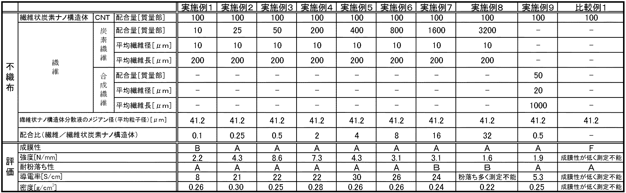
(実施例1)
<繊維の準備>
繊維としてピッチ系炭素繊維(三菱樹脂株式会社製、ダイアリード(登録商標)K223HM)を準備した。
なお、走査型電子顕微鏡(日立ハイテクノロジーズ製、S−4300)を用いて測定したピッチ系炭素繊維の平均繊維径は、10μmであった。また、走査型電子顕微鏡(日立ハイテクノロジーズ製、S−4300)を用いて測定したピッチ系炭素繊維の平均繊維長は、200μmであった。
<分散液の調製>
BET比表面積が600m2/g以下の繊維状炭素ナノ構造体である多層CNT(KUMHO PETROCHEMICAL社製、商品名「K−NANO」、平均繊維径:13nm、平均繊維長:30μm、BET比表面積:266m2/g)400mgを、2Lのメチルエチルケトン中に投入し、ホモジナイザーにより2分間撹拌して粗分散液を調製した。
次に、得られた粗分散液を、直径0.5mmの細管流路を備えた湿式ジェットミル(株式会社常光製、JN20)に100MPaの圧力で2サイクル通過させ、繊維状炭素ナノ構造体をメチルエチルケトン中に分散させて濃度0.20%の繊維状炭素ナノ構造体分散液を得た。なお、レーザー回折/散乱式粒子径分布測定装置(堀場製作所製、LA−960)にて繊維状炭素ナノ構造体分散液中の繊維状炭素ナノ構造体のメジアン径(体積換算の平均粒子径)を測定したところ、メジアン径は41.2μmであった。
その後、得られた繊維状炭素ナノ構造体分散液に対し、繊維としてのピッチ系炭素繊維を40mg投入し、ホモジナイザーにより2分間撹拌して分散液を得た。
<不織布の製造>
得られた分散液16gをキリヤマろ紙(No.5A、直径3cm)を用いて減圧ろ過し、ろ物を温度80℃の雰囲気下で60分間乾燥させてシート状の不織布を得た。そして、室温まで冷却した後、ろ紙上で不織布の成膜性を評価し、その後、不織布をろ紙から剥がし、不織布の強度、耐粉落ち性、導電率、及び密度を評価した。結果を表2に示す。
Example 1
<Fiber preparation>
Pitch-based carbon fibers (Made by Mitsubishi Plastics, DIALEAD (registered trademark) K223HM) were prepared as the fibers.
In addition, the average fiber diameter of the pitch-type carbon fiber measured using the scanning electron microscope (Hitachi High-Technologies make, S-4300) was 10 micrometers. Moreover, the average fiber length of the pitch-type carbon fiber measured using the scanning electron microscope (Hitachi High-Technologies make, S-4300) was 200 micrometers.
<Preparation of dispersion>
Multi-walled CNT (Fibre Carbon Nanostructure, manufactured by KUMHO PETROCHEMICAL, trade name “K-NANO”, average fiber diameter: 13 nm, average fiber length: 30 μm, BET specific surface area: BET specific surface area of 600 m 2 / g or less 266 m 2 / g) was poured into 2 L of methyl ethyl ketone and stirred for 2 minutes with a homogenizer to prepare a crude dispersion.
Next, the obtained coarse dispersion is passed through a wet jet mill (manufactured by Joko Co., Ltd., JN20) having a narrow tube flow path having a diameter of 0.5 mm for two cycles at a pressure of 100 MPa, so that the fibrous carbon nanostructure is obtained. A fibrous carbon nanostructure dispersion having a concentration of 0.20% was obtained by dispersing in methyl ethyl ketone. In addition, the median diameter (average particle diameter in terms of volume) of the fibrous carbon nanostructure in the fibrous carbon nanostructure dispersion using a laser diffraction / scattering particle size distribution measuring apparatus (LA-960, manufactured by Horiba, Ltd.) Was measured, and the median diameter was 41.2 μm.
Thereafter, 40 mg of pitch-based carbon fibers as fibers were added to the obtained fibrous carbon nanostructure dispersion liquid, and stirred for 2 minutes with a homogenizer to obtain a dispersion liquid.
<Manufacture of non-woven fabric>
16 g of the obtained dispersion was filtered under reduced pressure using Kiriyama filter paper (No. 5A, diameter 3 cm), and the filtrate was dried in an atmosphere at a temperature of 80 ° C. for 60 minutes to obtain a sheet-like nonwoven fabric. And after cooling to room temperature, the film-forming property of the nonwoven fabric was evaluated on the filter paper, and then the nonwoven fabric was peeled off from the filter paper, and the strength, dust resistance, electrical conductivity, and density of the nonwoven fabric were evaluated. The results are shown in Table 2.
(実施例2〜8)
繊維の配合量を表2に記載の通りに変更した以外は実施例1と同様にして不織布を製造し、得られた不織布について成膜性、強度、耐粉落ち性、導電率、及び密度を評価した。結果を表2に示す。
(Examples 2 to 8)
A nonwoven fabric was produced in the same manner as in Example 1 except that the amount of fibers was changed as shown in Table 2, and the film forming properties, strength, anti-powder resistance, conductivity, and density of the obtained nonwoven fabric were changed. evaluated. The results are shown in Table 2.
(実施例9)
<繊維の準備>
繊維として、合成繊維であるポリパラフェニレンベンズオキサゾール繊維(東洋紡株式会社製、商品名「Zylon HM(登録商標)」)を準備した。
なお、走査型電子顕微鏡(日立ハイテクノロジーズ製、S−4300)を用いて測定した合成繊維の平均繊維径は、20μmであった。また、走査型電子顕微鏡(日立ハイテクノロジーズ製、S−4300)を用いて測定した合成繊維の平均長さは、1000μmであった。
<分散液の調製>
実施例1と同様にして得た繊維状炭素ナノ構造体分散液に対し、繊維としての合成繊維を200mg投入し、ホモジナイザーにより2分間撹拌して分散液を得た。
<不織布の製造>
上述のようにして得られた分散液から、実施例1と同様にして不織布を製造した。得られた不織布について成膜性、強度、耐粉落ち性、導電率、及び密度を評価した。結果を表2に示す。
Example 9
<Fiber preparation>
As a fiber, a polyparaphenylene benzoxazole fiber (manufactured by Toyobo Co., Ltd., trade name “Zylon HM (registered trademark)”), which is a synthetic fiber, was prepared.
In addition, the average fiber diameter of the synthetic fiber measured using the scanning electron microscope (Hitachi High-Technologies make, S-4300) was 20 micrometers. Moreover, the average length of the synthetic fiber measured using the scanning electron microscope (Hitachi High-Technologies make, S-4300) was 1000 micrometers.
<Preparation of dispersion>
200 mg of synthetic fiber as a fiber was added to the fibrous carbon nanostructure dispersion liquid obtained in the same manner as in Example 1, and the mixture was stirred for 2 minutes with a homogenizer to obtain a dispersion liquid.
<Manufacture of non-woven fabric>
A nonwoven fabric was produced in the same manner as in Example 1 from the dispersion liquid obtained as described above. The resulting nonwoven fabric was evaluated for film formability, strength, anti-powder resistance, electrical conductivity, and density. The results are shown in Table 2.
(比較例1)
繊維を使用することなく、濃度0.20%の繊維状炭素ナノ構造体分散液のみを用いて不織布を製造した。具体的には、16gの繊維状炭素ナノ構造体分散液をキリヤマろ紙(No.5A、直径3cm)を用いて減圧ろ過し、ろ物を温度80℃の雰囲気下で60分間乾燥させてシート状の不織布を製造した。そして、実施例1と同様にして成膜性、強度、耐粉落ち性、導電性、及び密度を評価した。結果を表2に示す。
(Comparative Example 1)
A non-woven fabric was produced using only a fibrous carbon nanostructure dispersion liquid having a concentration of 0.20% without using fibers. Specifically, 16 g of fibrous carbon nanostructure dispersion liquid was filtered under reduced pressure using Kiriyama filter paper (No. 5A, diameter 3 cm), and the filtrate was dried in an atmosphere at a temperature of 80 ° C. for 60 minutes to form a sheet. A non-woven fabric was produced. In the same manner as in Example 1, the film formability, strength, dust resistance, conductivity, and density were evaluated. The results are shown in Table 2.
表2から、BET比表面積が600m2/g以下の繊維状炭素ナノ構造体と、繊維とを含む実施例1〜9にかかる不織布は、成膜性に優れることが分かる。なかでも、実施例2〜6にかかる不織布は耐粉落ち性も良好であり、さらに、実施例2〜5にかかる不織布は強度および導電性の双方が著しく向上していることが分かる。 From Table 2, it turns out that the nonwoven fabric concerning Examples 1-9 containing the fibrous carbon nanostructure whose BET specific surface area is 600 m < 2 > / g or less, and a fiber is excellent in film formability. Especially, it turns out that the nonwoven fabric concerning Examples 2-6 is also excellent in powder-proofing property, and also the nonwoven fabric concerning Examples 2-5 is improving both intensity | strength and electroconductivity remarkably.
本発明によれば、シート状部材として使用可能な、BET比表面積が600m2/g以下の繊維状炭素ナノ構造体を用いた不織布を得ることができる。 According to this invention, the nonwoven fabric using the fibrous carbon nanostructure whose BET specific surface area which can be used as a sheet-like member is 600 m < 2 > / g or less can be obtained.
Claims (8)
BET比表面積が600m2/g以下の繊維状炭素ナノ構造体と、繊維と、分散媒とを含む分散液から前記分散媒を除去して不織布を形成する工程を含む、不織布製造方法。 It is a manufacturing method of the nonwoven fabric in any one of Claims 1-6,
A non-woven fabric manufacturing method comprising a step of forming a non-woven fabric by removing the dispersion medium from a dispersion liquid containing a fibrous carbon nanostructure having a BET specific surface area of 600 m 2 / g or less, fibers, and a dispersion medium.
A coarse dispersion obtained by adding the fibrous carbon nanostructure to the dispersion medium is pumped to a capillary channel at a pressure of 60 MPa or more and 200 MPa or less, and a shear force is applied to the coarse dispersion to obtain an average particle size. The nonwoven fabric according to claim 7, further comprising a step of preparing the dispersion by mixing the fiber with the fibrous carbon nanostructure dispersion after obtaining a dispersion of the fibrous carbon nanostructure having a size of 60 µm or less. Production method.
Priority Applications (1)
| Application Number | Priority Date | Filing Date | Title |
|---|---|---|---|
| JP2015124040A JP6648423B2 (en) | 2015-06-19 | 2015-06-19 | Nonwoven fabric and method for producing the same |
Applications Claiming Priority (1)
| Application Number | Priority Date | Filing Date | Title |
|---|---|---|---|
| JP2015124040A JP6648423B2 (en) | 2015-06-19 | 2015-06-19 | Nonwoven fabric and method for producing the same |
Publications (2)
| Publication Number | Publication Date |
|---|---|
| JP2017008437A true JP2017008437A (en) | 2017-01-12 |
| JP6648423B2 JP6648423B2 (en) | 2020-02-14 |
Family
ID=57762927
Family Applications (1)
| Application Number | Title | Priority Date | Filing Date |
|---|---|---|---|
| JP2015124040A Active JP6648423B2 (en) | 2015-06-19 | 2015-06-19 | Nonwoven fabric and method for producing the same |
Country Status (1)
| Country | Link |
|---|---|
| JP (1) | JP6648423B2 (en) |
Cited By (2)
| Publication number | Priority date | Publication date | Assignee | Title |
|---|---|---|---|---|
| KR20180116023A (en) * | 2017-04-14 | 2018-10-24 | 원광대학교산학협력단 | Carbon fiber composite comprising unwoven carbon fabric coated with carbon nanotube, method for manufacturing the same and use thereof |
| JP2020117283A (en) * | 2019-01-24 | 2020-08-06 | 株式会社大成化研 | Oxygen barrier material and manufacturing method thereof |
Citations (7)
| Publication number | Priority date | Publication date | Assignee | Title |
|---|---|---|---|---|
| JP2004504688A (en) * | 2000-04-17 | 2004-02-12 | テクニカル、ファイバー、プロダクツ、リミテッド | Conductive sheet material |
| JP2004103403A (en) * | 2002-09-10 | 2004-04-02 | Noritake Co Ltd | Porous carbon sheet material and its manufacturing method |
| JP2009541051A (en) * | 2006-06-26 | 2009-11-26 | イリノイ トゥール ワークス インコーポレイティド | Antistatic paint cub |
| JP2011241499A (en) * | 2010-05-18 | 2011-12-01 | Yokohama National Univ | Good containing carbon nanotube |
| JP2014012902A (en) * | 2012-07-03 | 2014-01-23 | Showa Denko Kk | Manufacturing method of composite carbon fiber |
| JP2014162692A (en) * | 2013-02-26 | 2014-09-08 | Nakashima Medical Co Ltd | Method for manufacturing ceramic composite material, and ceramic composite material |
| WO2015015758A1 (en) * | 2013-07-31 | 2015-02-05 | 日本ゼオン株式会社 | Method for producing carbon nanotube dispersion, method for producing composite material composition, method for producing composite material, composite material, and composite-material molded product |
-
2015
- 2015-06-19 JP JP2015124040A patent/JP6648423B2/en active Active
Patent Citations (7)
| Publication number | Priority date | Publication date | Assignee | Title |
|---|---|---|---|---|
| JP2004504688A (en) * | 2000-04-17 | 2004-02-12 | テクニカル、ファイバー、プロダクツ、リミテッド | Conductive sheet material |
| JP2004103403A (en) * | 2002-09-10 | 2004-04-02 | Noritake Co Ltd | Porous carbon sheet material and its manufacturing method |
| JP2009541051A (en) * | 2006-06-26 | 2009-11-26 | イリノイ トゥール ワークス インコーポレイティド | Antistatic paint cub |
| JP2011241499A (en) * | 2010-05-18 | 2011-12-01 | Yokohama National Univ | Good containing carbon nanotube |
| JP2014012902A (en) * | 2012-07-03 | 2014-01-23 | Showa Denko Kk | Manufacturing method of composite carbon fiber |
| JP2014162692A (en) * | 2013-02-26 | 2014-09-08 | Nakashima Medical Co Ltd | Method for manufacturing ceramic composite material, and ceramic composite material |
| WO2015015758A1 (en) * | 2013-07-31 | 2015-02-05 | 日本ゼオン株式会社 | Method for producing carbon nanotube dispersion, method for producing composite material composition, method for producing composite material, composite material, and composite-material molded product |
Cited By (4)
| Publication number | Priority date | Publication date | Assignee | Title |
|---|---|---|---|---|
| KR20180116023A (en) * | 2017-04-14 | 2018-10-24 | 원광대학교산학협력단 | Carbon fiber composite comprising unwoven carbon fabric coated with carbon nanotube, method for manufacturing the same and use thereof |
| KR101976129B1 (en) * | 2017-04-14 | 2019-05-07 | 원광대학교산학협력단 | Carbon fiber composite comprising unwoven carbon fabric coated with carbon nanotube, method for manufacturing the same and use thereof |
| JP2020117283A (en) * | 2019-01-24 | 2020-08-06 | 株式会社大成化研 | Oxygen barrier material and manufacturing method thereof |
| JP7210012B2 (en) | 2019-01-24 | 2023-01-23 | 株式会社大成化研 | Oxygen barrier material and manufacturing method thereof |
Also Published As
| Publication number | Publication date |
|---|---|
| JP6648423B2 (en) | 2020-02-14 |
Similar Documents
| Publication | Publication Date | Title |
|---|---|---|
| JP7218770B2 (en) | Conductive nonwoven fabric and manufacturing method thereof | |
| JP6217395B2 (en) | Dispersion of carbon nanotube-containing composition and conductive molded body | |
| Meng et al. | Carbon nanotubes enhanced cellulose nanocrystals films with tailorable electrical conductivity | |
| KR102576626B1 (en) | Carbon film and its manufacturing method | |
| US20220185669A1 (en) | Carbon sheet | |
| US10995223B2 (en) | Fibrous carbon nanostructure dispersion liquid | |
| JP6648423B2 (en) | Nonwoven fabric and method for producing the same | |
| JP6455336B2 (en) | Thermal conductive sheet and manufacturing method thereof | |
| US10611640B2 (en) | Carbon film and method of producing same, and fibrous carbon nanostructure dispersion liquid and method of producing same | |
| WO2022229962A1 (en) | Extrudable compositions comprising polymeric particles coated by carbon nanotubes | |
| WO2017038413A1 (en) | Method for manufacturing composite material, and composite material | |
| JPWO2015045417A1 (en) | Method for producing carbon nanotube dispersion | |
| WO2019188977A1 (en) | Free-standing film, laminate, and method of manufacturing free-standing film | |
| Wang et al. | Surface decoration and dispersibility of carbon nanofibers in aqueous surfactant solution | |
| JPWO2016143299A1 (en) | Method for producing composite material and composite material | |
| Cauchy | Approaching Typical Metallic Conductivities in Polymer Nanocomposites for Lightning Strike Protection | |
| WO2019188978A1 (en) | Method of manufacturing carbon film | |
| Hajian et al. | Conductive and strong nanocomposites based on cellulose nanofibrils and carbon nanotubes |
Legal Events
| Date | Code | Title | Description |
|---|---|---|---|
| A621 | Written request for application examination |
Free format text: JAPANESE INTERMEDIATE CODE: A621 Effective date: 20180316 |
|
| A977 | Report on retrieval |
Free format text: JAPANESE INTERMEDIATE CODE: A971007 Effective date: 20180911 |
|
| A131 | Notification of reasons for refusal |
Free format text: JAPANESE INTERMEDIATE CODE: A131 Effective date: 20180925 |
|
| A601 | Written request for extension of time |
Free format text: JAPANESE INTERMEDIATE CODE: A601 Effective date: 20181119 |
|
| A521 | Request for written amendment filed |
Free format text: JAPANESE INTERMEDIATE CODE: A523 Effective date: 20190122 |
|
| A131 | Notification of reasons for refusal |
Free format text: JAPANESE INTERMEDIATE CODE: A131 Effective date: 20190625 |
|
| A521 | Request for written amendment filed |
Free format text: JAPANESE INTERMEDIATE CODE: A523 Effective date: 20190730 |
|
| TRDD | Decision of grant or rejection written | ||
| A01 | Written decision to grant a patent or to grant a registration (utility model) |
Free format text: JAPANESE INTERMEDIATE CODE: A01 Effective date: 20191217 |
|
| A61 | First payment of annual fees (during grant procedure) |
Free format text: JAPANESE INTERMEDIATE CODE: A61 Effective date: 20191230 |
|
| R150 | Certificate of patent or registration of utility model |
Ref document number: 6648423 Country of ref document: JP Free format text: JAPANESE INTERMEDIATE CODE: R150 |
|
| R250 | Receipt of annual fees |
Free format text: JAPANESE INTERMEDIATE CODE: R250 |
|
| R250 | Receipt of annual fees |
Free format text: JAPANESE INTERMEDIATE CODE: R250 |