JP2015525054A5 - - Google Patents
Download PDFInfo
- Publication number
- JP2015525054A5 JP2015525054A5 JP2015521638A JP2015521638A JP2015525054A5 JP 2015525054 A5 JP2015525054 A5 JP 2015525054A5 JP 2015521638 A JP2015521638 A JP 2015521638A JP 2015521638 A JP2015521638 A JP 2015521638A JP 2015525054 A5 JP2015525054 A5 JP 2015525054A5
- Authority
- JP
- Japan
- Prior art keywords
- solar cell
- cell array
- signal
- circuit
- switch
- Prior art date
- Legal status (The legal status is an assumption and is not a legal conclusion. Google has not performed a legal analysis and makes no representation as to the accuracy of the status listed.)
- Pending
Links
- 238000001514 detection method Methods 0.000 claims description 50
- 230000004907 flux Effects 0.000 claims description 12
- 210000004027 cells Anatomy 0.000 description 123
- 230000001629 suppression Effects 0.000 description 32
- 239000002131 composite material Substances 0.000 description 14
- 238000004891 communication Methods 0.000 description 11
- 238000005516 engineering process Methods 0.000 description 10
- 238000010891 electric arc Methods 0.000 description 8
- 238000010586 diagram Methods 0.000 description 6
- 238000001914 filtration Methods 0.000 description 6
- 238000010248 power generation Methods 0.000 description 6
- 238000004804 winding Methods 0.000 description 6
- 239000003990 capacitor Substances 0.000 description 4
- 239000000203 mixture Substances 0.000 description 4
- 239000004020 conductor Substances 0.000 description 3
- 238000009434 installation Methods 0.000 description 3
- 238000000034 method Methods 0.000 description 3
- 239000007787 solid Substances 0.000 description 3
- 239000007858 starting material Substances 0.000 description 3
- 230000003750 conditioning Effects 0.000 description 2
- 230000005669 field effect Effects 0.000 description 2
- 239000000463 material Substances 0.000 description 2
- 229910044991 metal oxide Inorganic materials 0.000 description 2
- 150000004706 metal oxides Chemical class 0.000 description 2
- 230000000051 modifying Effects 0.000 description 2
- 230000003287 optical Effects 0.000 description 2
- 230000004044 response Effects 0.000 description 2
- 239000004065 semiconductor Substances 0.000 description 2
- 230000003213 activating Effects 0.000 description 1
- 230000003321 amplification Effects 0.000 description 1
- 230000002238 attenuated Effects 0.000 description 1
- 239000004566 building material Substances 0.000 description 1
- 239000006227 byproduct Substances 0.000 description 1
- 239000000969 carrier Substances 0.000 description 1
- 230000001413 cellular Effects 0.000 description 1
- 210000003850 cellular structures Anatomy 0.000 description 1
- 230000001808 coupling Effects 0.000 description 1
- 238000010168 coupling process Methods 0.000 description 1
- 238000005859 coupling reaction Methods 0.000 description 1
- 230000005857 detection of stimulus Effects 0.000 description 1
- 229920005570 flexible polymer Polymers 0.000 description 1
- 239000011521 glass Substances 0.000 description 1
- 239000007943 implant Substances 0.000 description 1
- 238000004519 manufacturing process Methods 0.000 description 1
- 239000012528 membrane Substances 0.000 description 1
- 230000005055 memory storage Effects 0.000 description 1
- 230000004048 modification Effects 0.000 description 1
- 238000006011 modification reaction Methods 0.000 description 1
- 238000003199 nucleic acid amplification method Methods 0.000 description 1
- 229920001690 polydopamine Polymers 0.000 description 1
- 230000003334 potential Effects 0.000 description 1
- 230000002104 routine Effects 0.000 description 1
- 238000000926 separation method Methods 0.000 description 1
- 239000000126 substance Substances 0.000 description 1
- 239000010409 thin film Substances 0.000 description 1
Images


Description
(関連出願の相互参照)
本出願は、PCT国際特許出願として2013年6月26日に出願され、2012年7月9日に出願された米国特許出願番号第61/669,415号の優先権を主張し、その開示はその全内容を引用することにより本明細書に組み込まれるものとする。
(Cross-reference of related applications)
This application claims priority from US Patent Application No. 61 / 669,415, filed June 26, 2013 as a PCT international patent application and filed July 9, 2012, the disclosure of which is The entire contents of which are incorporated herein by reference.
2011年版米国電気コード(NEC)690.11は新型太陽電池設備に関連して電気アーク放電を検知及び抑制する両方の要件を含んでいる。 The 2011 National Electrical Code (NEC) 690.11 includes both requirements for detecting and suppressing electrical arcing in connection with new solar cell equipment.
多くの場合、従来のラックマウント太陽電池パネルは、回路の遮断がアークを消滅するのに十分であるようにつなぎ合わされている。このようなシステムでは100Vより大きな電圧電位が同じパネル中に存在することは稀である。従って、太陽電池産業は一連のアークを検知すること及び抑制することに焦点を置いている。しかし、太陽電池が建物の外装材(時々建物一体型太陽電池又はBIPVと呼ばれる)として機能もする設計を含め、代替の太陽電池設計及び設備が開発されるにつれて、あるシステム及びアレイの設計は電気バスラインの近くに潜在的に比較的高い電圧をもたらす。しかし、多数のBIPV部材から構成されるある配列では、家庭内ランバスが動作バスに平行に走り、いくつかの屋根板は2つのバス間で600Vまでの電位を有する。このような場合、直列及び並列アーク放電の両方が理論的に可能である。 In many cases, conventional rack-mount solar panels are stitched together such that circuit interruption is sufficient to extinguish the arc. In such systems, voltage potentials greater than 100V are rarely present in the same panel. The solar cell industry is therefore focused on detecting and suppressing a series of arcs. However, as alternative solar cell designs and equipment are developed, including designs where solar cells also function as building exterior materials (sometimes referred to as building-integrated solar cells or BIPV), certain system and array designs are Potentially a relatively high voltage near the bus line. However, in some arrangements composed of multiple BIPV members, a home run bus runs parallel to the operating bus and some roofing boards have a potential of up to 600V between the two buses. In such cases, both series and parallel arc discharge are theoretically possible.
一態様では、本技術は、太陽電池アレイシステムを形成する時に有用な太陽電池アレイキットに関する。キットは太陽電池アレイ回路に接続するためのコネクタを有する導通信号発生器を有し、導通信号発生器は太陽電池アレイ回路へ導通信号を送信するように適合される。キットは更に、太陽電池アレイ回路に接続するためのコネクタを有する検知回路を備え、検知回路は、導通信号センサと、太陽電池アレイ回路を選択的に開閉するための少なくとも1つのスイッチと、スイッチ及び導通信号センサに動作可能に接続されたスイッチコントローラと、を含む。スイッチコントローラは電源に接続するためのコネクタを備え、スイッチコントローラは検知回路からの制御信号の受信によってスイッチを作動させるように適合されている。一実施形態では、太陽電池アレイキットは太陽電池アレイ回路及び検出回路に接続するためのコネクタを有する少なくとも1つの太陽電池セルを含む。他の実施形態では、制御信号は導通信号を含む。更に別の実施形態では、検知回路は更に太陽電池アレイ信号を増幅するための増幅器及び太陽電池アレイ信号をフィルタリングするためのフィルタを含み、太陽電池アレイ信号は導通信号を含む。更に別の実施形態では、スイッチコントローラは太陽電池アレイ回路とは別個の電源に接続するように適合されている。 In one aspect, the present technology relates to a solar cell array kit useful when forming a solar cell array system. The kit includes a conduction signal generator having a connector for connecting to the solar cell array circuit, the conduction signal generator being adapted to transmit a conduction signal to the solar cell array circuit. The kit further comprises a sensing circuit having a connector for connecting to the solar cell array circuit, the sensing circuit comprising: a conduction signal sensor; at least one switch for selectively opening and closing the solar cell array circuit; And a switch controller operably connected to the conduction signal sensor. The switch controller includes a connector for connecting to a power source, and the switch controller is adapted to operate the switch upon receipt of a control signal from the sensing circuit. In one embodiment, the solar cell array kit includes at least one solar cell having a connector for connecting to the solar cell array circuit and the detection circuit. In other embodiments, the control signal includes a conduction signal. In yet another embodiment, the sensing circuit further comprises a filter for filtering the amplifier and solar array signal for amplifying the solar cell array signals, solar array signal includes a conductive signal. In yet another embodiment, the switch controller is adapted to connect to a power source separate from the solar array circuit.
上記態様の別の実施形態において、スイッチコントローラコネクタは、太陽電池アレイ回路に接続するように適合され、太陽電池アレイ回路はスイッチに電力を供給するように適合されている。更に別の実施形態では、太陽電池アレイ回路とは別個の電源は、スイッチコントローラコネクタに接続するためのコネクタを含む別個の太陽電池発電セルと、第1のインダクタ及び第2のインダクタを含む磁束発生器と、の少なくとも1つを含み、第1のインダクタ及び第2のインダクタは第1のインダクタと第2のインダクタとの間に磁束を発生するように配置され、第2のインダクタはスイッチコントローラコネクタに接続するためのコネクタを有している。更に別の実施形態では、少なくとも1つのスイッチは、金属酸化物半導体電界効果型トランジスタ、ソリッドステートスイッチ、及び機械式スイッチの少なくとも1つを含む。 In another embodiment of the above aspect, the switch controller connector is adapted to connect the solar cell array circuit, a solar cell array circuit is adapted to supply power to the switch. In yet another embodiment, a separate power supply is a solar cell array circuit, a magnetic flux occurs which includes a separate photovoltaic power generation cells including a connector for connecting to switch controller connector, a first inductor and a second inductor And the first inductor and the second inductor are arranged to generate a magnetic flux between the first inductor and the second inductor, the second inductor being a switch controller connector It has a connector for connecting to. In yet another embodiment, the at least one switch comprises a metal oxide semiconductor field effect transistor, solid state switches, and at least one of the mechanical switch.
上記態様の別の実施形態では、連続信号センサは、トランジスタ、アンテナ、及び有線接続部の少なくとも1つを含む。 In another embodiment of the above aspect, the continuous signal sensor includes at least one of a transistor, an antenna, and a wired connection.
別の態様では、本技術は太陽電池アレイ回路を維持するための方法に関し、本方法は、太陽電池アレイ回路上の太陽電池信号を検知する工程、及び太陽電池アレイ信号中の導通信号の存在に基づいて制御信号を太陽電池アレイ回路のスイッチに送信する工程と、を含む。一実施形態では、本方法は導通信号を発生する工程、及び導通信号を太陽電池アレイ回路に送信する工程を更に含む。別の実施形態では、本方法は制御信号の受信に基づいて太陽電池アレイ回路を閉じる工程を更に含む。更に別の実施形態では、制御信号は導通信号を含む。更に別の実施形態では、太陽電池アレイ信号は直流成分を含み、導通信号は交流成分を含む。 In another aspect, the present technology relates to a method for maintaining a solar cell array circuit, the method comprising detecting a solar cell signal on the solar cell array circuit and the presence of a conduction signal in the solar cell array signal. And transmitting a control signal to a switch of the solar cell array circuit based on. In one embodiment, the method further includes generating a conduction signal and transmitting the conduction signal to the solar cell array circuit. In another embodiment, the method further includes closing the solar array circuit based on receiving the control signal. In yet another embodiment, the control signal includes a conduction signal. In yet another embodiment, the solar cell array signal includes a direct current component and the conduction signal includes an alternating current component.
上記態様の別の実施形態では、太陽電池アレイ信号は少なくとも1つの太陽電池セルによって発生する。更に別の実施形態では、本方法は検知された太陽電池アレイ信号をフィルタリングする工程、検知された太陽電池アレイ信号を増幅する工程、及び検知された太陽電池アレイ信号を整流する工程の少なくとも1つの工程を更に含む。更に別の実施形態では、本方法は太陽電池アレイ回路とは別個の電源からスイッチに電力を供給する工程を更に含む。 In another embodiment of the above aspect, the solar array signal is generated by at least one solar cell. In yet another embodiment, the method step of filtering the solar cell array signal detected, step amplifies the sensed solar cell array signals, and detected in the step of rectifying the solar cell array signal at least one The method further includes a step. In yet another embodiment, the method further includes powering the switch from a power source separate from the solar array circuit.
上記態様の別の実施形態では、電源は、太陽電池アレイ回路とは別個の太陽電池セル、磁束発生器、及び建築物電力サービスの少なくとも1つを含む。更に別の実施形態では、本方法は太陽電池アレイ回路からスイッチに電力を供給する工程を含む。更に別の実施形態では、太陽電池アレイ信号は、アンテナ、変圧器、及び有線接続部の少なくとも1つを介して検知される。 In another embodiment of the above aspect, the power source includes at least one of a solar cell, a magnetic flux generator, and a building power service separate from the solar array circuit. In yet another embodiment, the method includes providing power to the switch from the solar cell array circuit. In yet another embodiment, the solar cell array signal is detected via at least one of an antenna, a transformer, and a wired connection.
現在好ましい実施形態が図に示される。しかし、本技術は示された正確な配置及び手段に限定されないと理解される。 A presently preferred embodiment is shown in the figure. It will be understood, however, that the technology is not limited to the precise arrangements and instrumentalities shown.
本明細書に記載の技術は住宅用太陽光市場における特定用途を有する。太陽光発電モジュールは、建物一体型太陽光発電装置(BIPV)とも呼ばれる建物一体型太陽電池モジュールである。これは屋根、天窓、又は建物正面のような建物外表面の一部において従来の建材を置き換えるために使われる。モジュールは柔軟なポリマーの屋根ふき用薄膜に、1つ以上の屋根ふき用屋根板に見えるように構成されているモジュール(例えば、ダウ・ケミカル・カンパニーによって作られたパワーハウス(POWERHOUSE)ブランドのBIPVの屋根板)に、又は一般的にガラス、若しくは同様な材料で作られた建築構成要素、例えば窓や天窓を置き換えるために使われる半透明モジュールに、一体化された薄膜太陽電池セルである。又は、太陽電池モジュールは、屋根等の建築構成要素に据え付けられたリジッドな太陽電池モジュールでも、又は大規模なフィールド・アレイ内に据え付けられたリジッドな太陽電池モジュールであってもよい。要するに本技術は、別個のセンサモジュール及び発電モジュールを有する建物一体型太陽電池又はアレイに限定されるものではない。 The technology described herein has particular application in the residential solar market. The photovoltaic power generation module is a building-integrated solar cell module that is also called a building-integrated photovoltaic power generation apparatus (BIPV). This is used to replace conventional building materials on parts of the building exterior such as roofs, skylights, or building facades. The module is a flexible polymer roofing membrane that is configured to look like one or more roofing roofing boards (eg, POWERHOUSE brand BIPV made by Dow Chemical Company) Thin-film solar cells integrated into semi-transparent modules used to replace building components generally made of glass or similar materials, such as windows and skylights. Alternatively, the solar cell module may be a rigid solar cell module installed in a building component such as a roof, or a rigid solar cell module installed in a large field array. In short, the present technology is not limited to building-integrated solar cells or arrays having separate sensor modules and power generation modules .
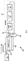
太陽電池アレイシステムにおいて断線を検知、及び電流を抑制するためのシステムは、小さなアレイ又は大規模フィールドアレイで用いられる従来のラックマウント太陽電池パネルと同様に、BIPV物品を利用する太陽電池アレイシステムと共に使用される。記載されたシステムのユニークな利点は、BIPVアレイ内においてそれらを特に有用にする。従って、その用途は、本明細書に記載されている。図1Aは、本明細書で説明されるシステム及び方法を組み合わせて使用することができる太陽電池アレイシステム100の設置を示す。システム100は、本体部分104及び太陽電池モジュール106の両方を含む多くの建物一体型太陽光発電装置102を含む。システム100は、太陽光発電装置102の端部に、又は太陽光発電装置102の少なくとも2つの行/列内に設置された少なくとも1つの縁片部108aを含む。更に、少なくとも1つのスタータ片108bと、少なくとも1つの間座108cと、少なくとも1つの縁片部108dとを利用することができる。これらの部品は、これらの部品を接続するために使用される構成要素同様、国際特許公開公報第2009/137,353号に記載され、その開示は参照することによりその全体が本明細書に組み込まれている。 Detecting disconnection in the solar cell array system, and a system for suppressing the current, as in the conventional rack-mount solar panels used in the small array or large field arrays, with solar array system utilizing BIPV article used. The unique advantages of the described system make them particularly useful within a BIPV array. Accordingly, its use is described herein. FIG. 1A illustrates the installation of a solar cell array system 100 that can be used in combination with the systems and methods described herein. The system 100 includes a number of building-integrated photovoltaic devices 102 that include both a body portion 104 and a solar cell module 106. The system 100 includes at least one edge piece 108a located at the end of the photovoltaic device 102 or in at least two rows / columns of the photovoltaic device 102. Further, at least one starter piece 108b, at least one spacer 108c, and at least one edge piece 108d can be utilized. These parts, as well as the components used to connect these parts, are described in International Patent Publication No. 2009 / 137,353, the disclosure of which is hereby incorporated by reference in its entirety. It is.
図1Bは、断線検知及び抑制システムを含む太陽電池アレイシステム150の実施形態の模式図である。このような実施形態は、建物又は建築物152上に据え付けられる。いくつかの実施形態では、建築物は、住宅若しくは商業建築物、車庫、物置、又は本明細書に開示された部品を組み込むための任意の他の適切な建築物であってもよい。建築部152はまた、屋根154及び壁などの支持構造物156を含む。図1Bに示すように、太陽電池アレイシステム150は、複数の発電モジュール164、又は太陽電池モジュールを含む。複数の発電装置モジュール164は、接続部162を介して断線検知システム160に結合されている。接続部162は有線接続部である。いくつかの実施形態では、断線検知システム160は、インバータを含むことができる太陽電池アレイシステム150のための制御/監視システム内に収容することができる。この実施形態では、断線検知システム160はまた、電源パネル158に接続されている。断線検知システム160は、電源パネル158に直接接続される必要はないことは、当業者によって認識される。 FIG. 1B is a schematic diagram of an embodiment of a solar cell array system 150 including a disconnection detection and suppression system. Such an embodiment is installed on a building or building 152. In some embodiments, the building may be a residential or commercial building, a garage, a storeroom, or any other suitable building for incorporating the components disclosed herein. Building portion 152 also includes a support structure 156 such as a roof 154 and walls. As shown in FIG. 1B, the solar cell array system 150 includes a plurality of power generation modules 164 or solar cell modules. The plurality of power generator modules 164 are coupled to the disconnection detection system 160 via the connection portion 162. The connection unit 162 is a wired connection unit. In some embodiments, the disconnect detection system 160 can be housed in a control / monitoring system for the solar cell array system 150 that can include an inverter. In this embodiment, the disconnection detection system 160 is also connected to the power panel 158. It will be appreciated by those skilled in the art that the disconnection detection system 160 need not be directly connected to the power panel 158.
図1Cは、図1Bの太陽電池アレイシステム150の拡大図である。太陽電池アレイシステム150は、建築物152の屋根154上の複数の発電装置モジュール164を含む。図示された実施形態では、15個の発電装置モジュール164が利用されている。しかし、個々の用途の必要に応じて任意の数の発電装置モジュールを含むことが可能である。住宅用途の場合、最大配列四角形の面積は多くの場合、例えば、屋根の大きさによって制限される。各発電装置モジュール164は5つの太陽電池セル166を含む。太陽電池用途で典型的であるように、発電装置モジュール164に接続された電源回路、又は太陽電池アレイ回路168は直列に配線されている。それぞれに含まれる太陽電池の数と同様に、特定用途の要求や必要に応じて、太陽電池セル又は発電装置モジュールの寸法は異なっていてもよい。異なる大きさ及び異なる構成モジュールを利用する太陽電池アレイシステムもまた考慮される。太陽電池アレイシステム150の他の構成要素を以下に説明する。 FIG. 1C is an enlarged view of the solar cell array system 150 of FIG. 1B. Solar cell array system 150 includes a plurality of generator modules 164 on roof 154 of building 152. In the illustrated embodiment, 15 power generator modules 164 are utilized. However, any number of generator modules can be included as required for individual applications. For residential applications, the area of the largest array square is often limited by, for example, the size of the roof. Each power generator module 164 includes five solar cells 166. As is typical in solar cell applications, the power supply circuit connected to the generator module 164 or the solar cell array circuit 168 is wired in series. Similar to the number of solar cells included in each, the dimensions of the solar cells or power generator modules may vary depending on the requirements and needs of the particular application. Solar cell array systems utilizing different sizes and different component modules are also contemplated. Other components of the solar cell array system 150 will be described below.
概して言えば、本明細書中に記載の技術で検知する断線は、2つのタイプのアーク放電を示している。バス経路のうちの1つで解放部が確立され、アークが解放部を渡るのに十分な電圧に解放部がさらされると、直列アークが発生する。直列アークは、「+」ラインバス上又は「−」ラインバス上のどこかで発生する。並列アークはバス電圧が「+」バスから「−」バスへの間隙を埋めるのに十分である場合に発生し、従って、「+」バスと「−」バスとの間のどこかで現れる。両タイプのアークは、屋根板アレイを介して同じ回路の制御信号の通信を妨害するのに十分な程、回路品質を劣化させる。 Generally speaking, the disconnection detected by the techniques described herein indicates two types of arcing. A series arc occurs when a release is established in one of the bus paths and the release is exposed to a voltage sufficient to cause the arc to cross the release. Series arcs occur somewhere on the “+” line bus or on the “−” line bus. A parallel arc occurs when the bus voltage is sufficient to fill the gap from the “+” bus to the “−” bus, and therefore appears somewhere between the “+” bus and the “−” bus. Both types of arc degrade circuit quality enough to interfere with the communication of control signals of the same circuit through the roofing board array.
図2は、種々の条件下におけるアレイ回路の模式図を示しており、直列及び並列アークの両方がそれに関連してより詳細に説明される。太陽電池アレイ回路であり得る基本的な演算回路は、パートAに示されている。回路は電源(アレイ回路内の、これは1つ以上の太陽電池セル、BIPV物品等とすることができる)、電力調整回路(例えば、電力網接続インバータ、DC−DCブースト回路、DC−DC降圧回路、又は帯電制御器など)、及び電源を負荷に接続する2つのリード線又は導体を含む。パートBは、直列と並列2つのタイプのアーク放電を示している。パートB1に示すように、直列アークは、電流を搬送する2つの導体の分離によって作成される。アーク放電は電気的負荷、配線等と直列になっている。任意の時点(パートC1参照)で回路が十分に抑制されると(回路を開くことにより、又は実質的に電流を減少させることによって)、パートD1に示すようにアークは消滅する。パートB2に示されるように、並列アークは導体間で、この場合には2本のリード線間で、最初は異なる電圧(例えば300V及び0V)で発生する。並列アークは別の負荷と並列に発生し、このように2つの負荷を形成する。そして、アークを隔てる電圧降下及び元の負荷はアークの電流−電圧特性によって決定される。元の負荷が削除されると、パートC2及びD2に示すように、アークは消滅しない。従って、回路はアークによって形成された回路と直列の位置で開放する必要がある。パートD2の場合には、アーク消弧するとアークと電源との間のリード線の残りの部分の上の回路を開く必要がある。アレイ回路上の様々な場所でスイッチ等の遮断器又は抑制デバイスを取り付けると、並列アークの場所に係らず回路を遮断することができ、その結果、並列アークを除去する適切な場所でアークを抑制することができる。 FIG. 2 shows a schematic diagram of an array circuit under various conditions, both series and parallel arcs being described in more detail in connection therewith. The basic operation circuit for obtaining Ri solar array circuit der is shown in Part A. The circuit is a power supply (in an array circuit, which can be one or more solar cells , BIPV articles, etc.), a power conditioning circuit (eg, power grid connected inverter, DC-DC boost circuit, DC-DC step-down circuit) Or a charge controller, etc.), and two leads or conductors that connect the power supply to the load. Part B shows two types of arc discharge in series and parallel. As shown in Part B1, a series arc is created by the separation of two conductors carrying current. Arc discharge is in series with electrical loads, wiring, etc. If the circuit is sufficiently constrained at any point in time (see Part C1) (by opening the circuit, or substantially reducing the current), the arc disappears as shown in Part D1. As shown in Part B2, parallel arcs occur between conductors, in this case between two leads, initially at different voltages (eg, 300V and 0V). A parallel arc occurs in parallel with another load, thus forming two loads. The voltage drop across the arc and the original load are determined by the current-voltage characteristics of the arc. When the original load is deleted, the arc does not disappear, as shown in parts C2 and D2. Thus, the circuit must be opened in a position in series with the circuit formed by the arc. In Part D2, arc extinguishing requires opening the circuit above the rest of the lead between the arc and the power source. Installing breakers or suppression devices such as switches at various locations on the array circuit can break the circuit regardless of the location of the parallel arc, and as a result, suppress the arc at the appropriate location to eliminate the parallel arc can do.
本明細書に記載されたシステム及び方法は、太陽電池アレイ回路内の断線、例えば太陽電池アレイ内のアーク放電又は他の異常によって生じる断線を検知する。より正確には、太陽電池アレイ回路を通過するコンポジット信号、又は太陽電池アレイ信号は、回路内の潜在的に望ましくない状態を示す異常、即ちアーク放電のために連続的に監視される。このコンポジット信号、又は太陽電池アレイ信号は2つの構成要素を有している。太陽光発電設置では典型的であるように、コンポジット信号の主構成要素は、太陽電池セルで発電した電力からであり、及び直流によって特徴付けられる。第2の構成要素は、太陽電池アレイ回路から遠隔で生成された交流電流を有する導通信号である。いくつかの実施形態では導通信号は矩形波、個々のパルス、又は当技術分野で公知の任意の他の信号であってもよい。この導通信号は、両方の構成要素が太陽電池アレイ回路の動作中に検知されるように、直流電力信号上に重ねられる。この複合信号内で検知された異常は、例えばコンポジット信号中の導通信号の欠落は、回路の終端を要求するアーク放電のような現象を示している。本明細書中に記載されたシステムでは、このような異常の検知に応答して回路を遮断する。このため回路を流れる電流を止め、発生する可能性のあるすべてのアーク放電を抑制する。しかし、導通信号が太陽電池アレイ信号中に存在する場合、システムは回路を閉じた状態にして電流を流す。従って、本明細書で記載されるシステム及び方法は、アーク放電の抑制が太陽電池アレイ回路遮断の副産物であっても、断線検知及びアーク放電抑制システムと呼ぶことができる。 The systems and methods described herein detect wire breaks in solar cell array circuits, such as wire breaks caused by arcing or other anomalies in the solar cell array . More precisely, the composite signal passing through the solar cell array circuit, or the solar cell array signal, is continuously monitored for abnormalities, i.e. arcing, indicative of potentially undesirable conditions in the circuit. This composite signal or solar cell array signal has two components. As is typical in photovoltaic installation, the main components of the composite signal is from the power generated by the solar cell, and is characterized by a direct current. The second component is a conduction signal having an alternating current generated remotely from the solar cell array circuit. In some embodiments, the conduction signal may be a square wave, individual pulses, or any other signal known in the art. This conduction signal is superimposed on the DC power signal so that both components are detected during operation of the solar cell array circuit. The abnormality detected in the composite signal indicates, for example, a phenomenon such as arc discharge that requires termination of the circuit when the conduction signal is missing in the composite signal. The system described herein shuts down the circuit in response to such an abnormality detection. This stops the current through the circuit and suppresses any arcing that can occur. However, if a conduction signal is present in the solar cell array signal, the system passes the current with the circuit closed. Accordingly, the system and method described herein can be referred to as a disconnection detection and arc discharge suppression system, even though suppression of arc discharge is a by-product of solar cell array circuit interruption.
図3A及び3Bは、断線検知及び抑制システム300の太陽電池アレイシステムの実施形態を示す。図3Aに示された断線検知及びアーク放電抑制システム300の実施形態は、太陽電池アレイ回路307上へ導通信号又はスティミュラス304を送信するインバータ302を含む。実施形態では、インバータ302は、インターネット又は他の通信ネットワークを介して手動又は遠隔制御することができ、どんな理由でもユーザが導通信号又はスティミュラス302を切断することを可能にする。スティミュラス304は、交流電流(AC)信号を含む当技術分野で公知の同定可能な任意のタイプの信号であってもよい。検知回路312は、導通信号センサを経由して太陽電池アレイ回路307上の信号を監視する。導通信号センサは特に、アンテナ308及び/又は有線接続310であってもよい。太陽電池アレイ回路307を監視する間、検知回路312はいくつかの構成要素を利用して太陽電池アレイ回路307上のスティミュラス304の存在を検知する。いくつかの実施形態では、これらの構成要素は、増幅器314、フィルタ316、及び出力318を含む。検知回路312は、多くの異なる場所に、例えばインバータ302内に、又は太陽電池アレイ306上の若しくは太陽電池アレイ306に隣接したスタータ片の中に遠く離れて収容されて、物理的に配置することができる。複数の検知回路312は1つの太陽電池アレイ306上でも使用することができる。例えば、検知回路312は太陽電池アレイ306の各列に含まれてもよい。
3A and 3B show an embodiment of the solar cell array system of the disconnection detection and
太陽電池アレイ回路307上の信号がアンテナ308を使用して監視される実施形態では、増幅器314は、アンテナ308によって検出された信号のための前置増幅器であってもよい。アンテナ信号の前置増幅は有用な信号を提供するが、信号を処理する必要がないことは当業者により認識される。太陽電池アレイ回路307上の信号が有線接続310を使用して監視される実施形態では、増幅器314は所望の用途に応じて検出された信号を増幅又は減衰させることもできる。アンテナ308及び/又は有線接続310を実施する両方の実施形態では、増幅器314は、演算増幅器(「オペアンプ」)、又は任意の他の増幅方法若しくは構成要素を含むことができる。
In embodiments where the signal on the
検知された信号が増幅器314によって増幅又は減衰された後、検知回路312のフィルタ316は検知された信号をフィルタリングする。フィルタ314は、スティミュラス304の検知を容易にするために検知された信号をフィルタリングするために使用される。例えば、スティミュラス304が比較的高い周波数を有する場合、フィルタ316はハイパスフィルタなどを含み、高周波数スティミュラスがフィルタを通過することを可能にする。スティミュラス304の用途及び特性に応じて、多くの異なるフィルタ、特に、ローパスフィルタ及びバンドパスフィルタなどを含むフィルタ316が実装される。更に、コンピュータ実行フィルタリングプログラム、又は他のフィルタリング方法及び装置が利用できる。
After the sensed signal is amplified or attenuated by
検知回路312の出力318は検知回路312の出力を制御し、いくつかの実施形態では、制御信号をスイッチ320に出力する。スティミュラス304が存在するか否かを決定するために、出力318はフィルタリングされた信号を所定のレベルと比較する回路を含むことができる。フィルタリングされた信号が所定のレベルと比較されるような実施形態では、出力コンポーネント318回路はコンパレータを含むことができる。電圧レベル、電流レベル、周波数、波形形状等の電気信号の特性を比較するための他の方法及び構成要素が考慮される。出力318が太陽電池アレイ306から検知されたコンポジット信号内のスティミュラス304の存在を検知するある実施形態では、出力318は、スイッチ320が閉じるべきか、又は閉じたままでいるかを指示する制御信号をスイッチ320に出力する。ある実施形態では、スティミュラス304は独立して生成された制御信号の代わりに出力318によって制御信号に変換される。他の実施形態では、スティミュラス304が存在する場合、出力318はスティミュラス信号がスイッチ320を通過することを可能にする。このような実施形態では、スティミュラス304の受信によりスイッチ320は閉じたり、又は閉じたままになったりする。スティミュラス304が存在しない場合は、信号はスイッチに到達せずスイッチが開く。あるいは、出力318は、スティミュラス304が太陽電池アレイ306上で検知されない後の時間の間、スイッチ320が閉じたままであることを示す信号をスイッチ320に出力し続けることができる。
The output 318 of the
スイッチ320は、太陽電池アレイ回路307を開くことができるような方法で太陽電池アレイ306に接続されている。スイッチ320は検知回路312の外側に位置するように図3Aに示されているが、いくつかの実施形態では、スイッチ320は検知回路312の一部であることができる。スティミュラス304が太陽電池アレイ回路307上に存在する時、スイッチ320は閉じたままである。スティミュラス304が検知回路312によって検知されない時、スイッチ320は開き、太陽電池アレイ回路307を遮断する。ある実施形態では、制御信号又はスティミュラス信号が検知回路312から、又はより具体的には出力318から受信される限りスイッチ320は閉じたままである。いくつかの実施形態では、機械式、他のソリッドステート、及びコンピュータ制御スイッチのような他のタイプのスイッチが考慮されるが、スイッチ320は、例えば金属酸化物半導体電界効果トランジスタ(MOSFET)などのトランジスタである。
The
検出回路312及びスイッチ320に電力を供給するための2つのオプションは、図3Aに示されている。電源322、例えば建物、サービスパネル、壁コンセント、又はバッテリーからの電力を利用できる。別の実施形態では、検出回路312及びスイッチ320への電力は、雨除け屋根板と呼ばれる別個の太陽電池発電セル又はモジュール324によって供給される。このような1つの別個のセル324は、「放射照度及び温度を測定するための光起電装置」と題するPCT出願国際公開第2012/074,808号に記載され、当該出願の全開示内容はここに引用することにより本明細書に盛り込まれている。このモジュール324の寸法は、アレイ306に容易に組み込まれるようにアレイ306で使用される太陽電池セルと実質的に同じであってもよい。アレイ中のセルと異なったサイズのモジュール324も考慮される。同一のモジュールが望ましい1つの用途は、美観が重要な決定要因である建物一体型太陽電池アレイシステムである。このような同一のモジュールは、取り付けの美観を損なうことなく直接太陽電池アレイ306に組み込むことができる。
Two options for supplying power to the
検知回路312の一例は図3Bに示されている。検出回路312は、2N4857トランジスタを利用したアンテナプリアンプ回路を含む増幅器314を含む。増幅器314に続いて、フィルタ316は、増幅された信号をフィルタリングするための回路を含む。この回路は標準LM358Nオペアンプを含む。フィルタ316の回路に続くのは、出力318の回路である。図3Bに示した例から分かるように、出力318のこの実施形態は、最初に別のLM358Nオペアンプを使用してゲインを調整する。そして、信号のレベルは、更に別のLM358Nオペアンプを用いて調整される。ある実施形態では、例えばスイッチ320がMOSFETである場合、スイッチ320に出力される信号がスイッチ320を閉じるために適切なレベルであるようにレベルが調整される。レベルシフトが発生した後、信号は出力フィルタを通過する。例えば図3Bに示されたような実施形態では、出力フィルタは、単純な並列抵抗−キャパシタフィルタ(RCフィルタ)である。
An example of the
図4は、断線検知及び抑制システム400を有する太陽電池アレイシステムの別の実施形態を示す。システム400の基本的な要素は、図3Aに示されたシステム300の基本的な要素に実質的に類似している。しかし、システム400内の検知回路412及びスイッチ420は別個の電源322、又は発電セル324によって電力を供給されないため、システム400はシステム300と異なる。その代わりに、接続426によって示されるように、検知回路412及びスイッチ420は太陽電池アレイ回路407自体から電力を引き出す。ある実施形態では、電圧調整回路は太陽電池アレイ406よって生成される広い範囲の電圧を処理するために使用される。太陽電池アレイの各列上に検知回路412及びスイッチ420がある実施形態では、太陽電池アレイ回路の各列はそれぞれの列上にある検知回路412及びスイッチ420にそれぞれ電力を供給することができる。
FIG. 4 illustrates another embodiment of a solar cell array system having a break detection and
図5は、断線検知及び抑制システム500を有する太陽電池アレイシステムの実施形態を示す。システム500の基本的な要素は図3Aに示したシステム300の基本的な要素に実質的に類似している。しかし、本実施形態では、検知回路512及びスイッチ520は、更に別の電源によって電力を供給される。システム500は、インバータ502、太陽電池アレイ回路507を有する太陽電池アレイ506、スイッチ520、検知回路512、スイッチ制御電源528、磁束発生器530及び、磁束発生用電源534を含む。磁束発生器530及びスイッチ制御電源528は、ルーフデッキ532の反対側に配置されている。ルーフデッキ532を介して結合した磁束は検出器512及びスイッチ520に電力を供給するために使用される。構成要素に電力を供給するこの方法は、ルーフデッキ532を介して追加の配線を通す必要を低減又は削減する。磁界は磁束発生器530によって生成され、ルーフデッキ532を通過する。この磁界は磁束発生器530のインダクタやソレノイドを通って電流を流すことにより、又は他の公知の方法又はシステムによって生成できる。磁界がルーフデッキ532を通過すると、磁界が電力を生成するために使用されるスイッチ制御電源528に磁界は到達する。例えば、磁場はスイッチ制御電源528の第2のインダクタを通過して流れる。このようにして、磁場はスイッチ制御電源528から電流を生成する。そしてスイッチ制御電源528から生成された電力は、検知回路512及びスイッチ520によって利用される。
FIG. 5 illustrates an embodiment of a solar cell array system having a disconnection detection and
図6A及び6Bは太陽電池アレイシステム600の断線を検出し、及び電流を抑制する回路を示している。システム600と以前記述したシステムとのいくつかの相違点は次に記載する。図6Aに示すように、システム600は太陽電池アレイ回路607上への導通信号又はスティミュラス604を送信するインバータ602を含む。スティミュラス604はAC信号又は電圧及び/又は電流を変化させる他の信号でもよい。変圧器636は太陽電池アレイ回路607にも取り付けられ、整流器638へ接続している。変圧器636はAC信号のような変化信号を、太陽電池アレイ回路607から整流器638へ送るだけである。しかし、上述したようにDC信号はアレイ606によって生成される。だからスティミュラス604が太陽電池アレイ回路607上に送信される場合、スティミュラス信号604だけが変圧器636を経由して整流器638へ流れる。スティミュラス604は変圧器636から整流器638へ送信されると、整流器638はスイッチ620に送信する又は通過できるようになる前に信号を整流する。ここでもまた、多くの異なった種類のスイッチ、例えば機械式、ソリッドステート、及びコンピュータ制御スイッチが、スイッチ620に適切であろう。導通信号604が太陽電池アレイ回路607上に存在する場合には、スイッチ620は閉じている、又は閉じたままになっている。だから閉じた太陽電池アレイ回路607を形成している。導通信号又はスティミュラス604が存在しない場合には、スイッチは開く。そして太陽電池アレイ回路607は開き、電流が流れるのを防ぐ。
6A and 6B show a circuit for detecting disconnection of the solar
太陽電池アレイシステム600内で断線を検出し及び電流を抑制する回路の一例は図6Bに示されている。I2はインバータ602を、及びR1は太陽電池アレイ負荷を表している。スイッチ620はMOSFETスイッチを含み、変圧器638はトロイダル型変圧器である。スイッチ620が閉じている時、太陽電池アレイ回路607からの電流は変圧器636の1次巻線を通して、そしてスイッチ620を通して流れる。スイッチ620が開いている時、DC電流はメインの太陽電池アレイ回路607を通して流れない。この実施形態では、整流器638は4つのダイオードを含む標準的な全波ブリッジ整流器であるが、しかし信号を整流する他の装置を利用することもできる。整流器638は変圧器636の2次巻線及びスイッチ620に接続している。変圧器636はスティミュラス信号604とだけに結合しアレイ606によって発生したDC信号とは結合しないため、スティミュラス604だけが整流器638に到達する。スティミュラス604が整流器638によって整流された後、信号はスイッチ620を閉じた状態に維持するように適切な電流レベルと電圧レベルのDC信号になる。図6Bに示したように、整流された信号はMOSFETの駆動ゲートに送出され、効果的にスイッチ620を閉じ、又はMOSFETを作動させる。スティミュラス604が存在する時、信号は変圧器636で結合せず、スイッチ620は開く。
An example of a circuit that detects disconnection and suppresses current in the solar
変圧器636上の2次巻線に対する1次巻線の比は、2次巻線にスイッチ620を閉じるために十分な電圧を生成するように選択される。ダイオードブリッジ整流器を利用する実施形態では、選択されたスティミュラス信号604を処理するに十分に高速なダイオードを実装することが望ましい。更に、整流された出力はスイッチ620に到達する前にフィルタリングされる。また、キャパシタは開かれた後にMOSFETが閉じることができるようにするためにMOSFETをまたいで配置されることができる。このキャパシタは図6BでC2として示されている。キャパシタを含むことにより、スイッチ620が開いている時にはスティミュラス604のようなAC電流は太陽電池アレイ回路を通過することができる。
The ratio of primary winding to secondary winding on
追加の要素又は構成要素は、必要に応じてシステム600に加えてもよい。変圧器636の二次巻線とスイッチ620との間のフィルタリング及び信号調整部品は、変圧器636で結合された交流電流がスティミュラス信号604と一致するかを検知するために使用される。太陽電池アレイ回路607からの結合された太陽電池アレイ信号がスティミュラス信号604の特性と一致しない場合、電気的ノイズのような誤った信号に基づいてその信号はフィルタ除去されてスイッチ620が閉じるのを防ぐ。MOSFETがスイッチ620として使用される場合も、MOSFETが完全にオン又は完全にオフになることを保証するために、デッドバンドをMOSFETのゲート駆動に加えてもよい。デッドバンドを追加するとMOSFETの線形応答を妨げ、MOSFETがオーバーヒートするおそれがある。図6A及び図6Bに示された多くの構成要素は、太陽電池アレイ606上に若しくは太陽電池アレイ606の下に直接配置されるスタータ片内に、又は太陽電池アレイ606に隣接する雨仕舞の一部に一体化される。システム600は、スイッチ620に電力を供給するために外部電源を必要としない。その代わりに、スイッチ620を制御するための電力は、スティミュラス信号604自体から直接来る。
Additional elements or components may be added to the
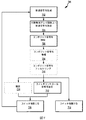
図7は、太陽電池アレイシステムにおける断線を検出し、及び電流を抑制するための方法700を示す。方法700は動作702で開始する。動作702において、スティミュラス又は導通信号は、例えばインバータ又は別個の構成要素として導通信号発生器によって生成する。導通信号は、太陽電池アレイ回路をテストするための別のテスト信号発生器によって生成することもできる。導通信号発生器は、インターネット又は他の通信ネットワークを介して手動又は遠隔制御することもでき、ユーザが何らかの理由で導通信号を中断することができる。導通信号が生成された後、動作704で導通信号は太陽電池アレイ回路上に送信される。動作706では、コンポジット信号又は太陽電池アレイ信号が除去される。コンポジット信号は、任意の信号又は太陽電池アレイ回路上に存在する信号、例えば太陽光発電電力モジュールによって生成された信号を含む。このため、導通信号が太陽電池アレイ回路上に発信された時、コンポジット信号は導通信号を含む。ある状況下では、他の信号は太陽電池アレイ回路上に存在しない。このためコンポジット信号を導通信号と確認できる。これはシステムがテストされ、テスト導通信号が電力を生成する太陽電池アレイ回路なしに発生される場合に、発生する。動作706におけるコンポジット信号の検知は、本明細書に記載されているように実施される。例えば、アンテナを使用して、又は太陽電池アレイ回路から検知回路に有線接続により、変圧器で信号と結合することにより信号は検知される。ある実施形態では、もしこのような機能がシステムに含まれているなら、コンポジット信号が動作706で検知されると、検知されたコンポジット信号は動作708で増幅され、動作710でフィルタリングされる。
FIG. 7 illustrates a
動作712では、制御信号はスイッチが閉じる必要があることを示すスイッチに送信される。ある実施形態では、制御信号は導通信号が検知された時に生成される。別の実施形態では、制御信号は導通信号自身であり、又はそれらからの派生信号である。例えば、導通信号が存在する場合、その信号はいくつかの方法で修正することができ、スイッチが閉じられるべきか閉じたままであるべきかを示す制御信号としてスイッチに渡される。別の実施形態では、動作714に示されるように制御信号は整流される。制御信号が存在する場合、それはスイッチに送信される前に整流される。整流制御信号は、スイッチが閉じられるべきか閉じたままであるべきかをスイッチに指示する。
In
動作716において、スイッチは制御信号又はスイッチが閉じられるべきか閉じたままであるかを示す導通信号を受信する。制御信号又は導通信号を受信すると、スイッチは閉じられるか又は閉じられたままである。例えばスイッチはMOSFETであり、MOSFETは、スイッチを閉鎖する電力をMOSFET上に送る制御信号又は整流導通信号をゲート駆動上で受信する。導通信号がコンポジット信号内に存在しない場合には、制御信号は全く送信されない。このように、導通信号が存在しない場合に、動作718でスイッチは開いたり、又は開いたままになったりする。スイッチを開くことにより、直流が太陽電池アレイ回路を通って流れず、その上に発現するどのような潜在的なアークも抑制される。
In
ある実施形態では、本明細書に開示された検出及び抑制システムは、BIPV又はその他の太陽電池部材の太陽電池アレイシステムに統合することができる。1つの検出及び抑制システム又は回路は、単一のアレイを用いてもよい。あるいは、複数の検出及び抑制システムは、単一のアレイで使用されてもよく、例えば、検出及び抑制システムは、アレイ内の太陽電池セルのサブセットに組み込むことができる。一実施形態では、検出及び抑制システムは、多列アレイの各列に含まれてもよい。複数の検知システムアレイでは、1つの検知器によるアーク放電の検出がすべての抑制装置においてアーク放電の抑制を開始できるように検知器を構成することができる。 In certain embodiments, the detection and suppression systems disclosed herein can be integrated into a solar cell array system of BIPV or other solar cell components. One detection and suppression system or circuit may use a single array. Alternatively, a plurality of detection and suppression system may be used in a single array, for example, detection and suppression system, can be incorporated into a subset of the solar cells in the array. In one embodiment, a detection and suppression system may be included in each column of the multi-column array. In a plurality of detection system arrays, the detector can be configured such that detection of arc discharge by one detector can initiate suppression of arc discharge in all suppression devices.
上記の検知及び抑制システムは、単一のパッケージ又は複数のパッケージのいずれかで、キットとして販売することができる。キットは、様々なシステムに上述した各種の構成要素を含むことができる、又はこれらの構成要素の各々は、個別に販売することができる。各システムは、アレイの他の構成要素と通信するための複数のコネクタを含む。キットに含まれる説明書には個々の装置に基づいて必要とされる配線の種類を指定しているが、望むなら配線を含むことができる。更に、システムは、システムを使用するために必要なソフトウェア又はファームウェアをロードしても又は含んでもよい。別の構成では、PCがアレイのパフォーマンスモニタとして使用される場合、又はPCがユーザ若しくはサービスインターフェースとしてアレイのパフォーマンスモニタと組み合わせて使用される場合、ソフトウェアは標準的なPCにアップロードするための各種の記憶媒体(CDやDVD、USBドライブなど)に含まれてもよい。更に、プログラムをインターネット上のウェブサイトからダウンロードするために、ウェブサイトのアドレス及びパスワードは、キットの説明書に含まれていてもよい。 The detection and suppression system described above can be sold as a kit in either a single package or multiple packages. The kit can include the various components described above in various systems, or each of these components can be sold separately. Each system includes a plurality of connectors for communicating with other components of the array. The instructions included in the kit specify the type of wiring required based on the individual device, but can include wiring if desired. In addition, the system may load or include software or firmware necessary to use the system. In another configuration, if the PC is used as an array performance monitor, or if the PC is used in combination with the array performance monitor as a user or service interface, the software can use various types of uploads to a standard PC. It may be included in a storage medium (CD, DVD, USB drive, etc.). Further, in order to download the program from a website on the Internet, the website address and password may be included in the kit instructions.
図8A及び本明細書における更なる考察は、本発明及び/又はその一部を実施することができる適切なコンピューティング環境を簡単に一般的に説明している。必要ではないが、本明細書に記載の実施形態は、例えばプログラムモジュールによって、コンピュータ実行可能命令として実施され、クラウド環境で動作するサーバを含むクライアントワークステーション又はサーバなどのコンピュータによって実行される。一般に、プログラムモジュールは、特定のタスクを実行する又は特定の抽象データタイプを実行するルーチン、プログラム、オブジェクト、コンポーネント、データ構造などを含む。更に、本技術及び/又はその一部は、ハンドヘルドデバイス、マルチプロセッサシステム、マイクロプロセッサベース又はプログラマブルコンシューマエレクトロニクス、ネットワークPC、ミニコンピュータ、及びメインフレームコンピュータなどを含む他のコンピュータシステム構成で実行されるものと理解される。本発明は、通信ネットワークを介してリンクされたリモート処理装置によってタスクが実行される分散コンピューティング環境で実施することもできる。分散コンピューティング環境では、プログラムモジュールはローカル及びリモートメモリ記憶装置の両方に配置することができる。 The further discussion in FIG. 8A and this specification briefly describes generally a suitable computing environment in which the invention and / or portions thereof may be implemented. Although not required, the embodiments described herein are implemented as computer-executable instructions, eg, by program modules, and are executed by a computer such as a client workstation or server that includes a server operating in a cloud environment. Generally, program modules include routines, programs, objects, components, data structures, etc. that perform particular tasks or perform particular abstract data types. Further, the present technology and / or portions thereof may be implemented in other computer system configurations including handheld devices, multiprocessor systems, microprocessor-based or programmable consumer electronics, network PCs, minicomputers, mainframe computers, etc. It is understood. The invention may also be practiced in distributed computing environments where tasks are performed by remote processing devices that are linked through a communications network. In a distributed computing environment, program modules can be located in both local and remote memory storage devices.
図8Aは、1つ以上の本実施形態を実施することができる適切な動作環境800の一例を示す図である。これは、適切な動作環境の一例に過ぎず、使用又は機能の範囲に関して限定を示唆するものではない。使用するのに適切な他の周知のコンピューティングシステム、環境、及び/又は構成としては、パーソナルコンピュータ、サーバコンピュータ、ハンドヘルド又はラップトップデバイス、マルチプロセッサシステム、マイクロプロセッサベースのシステム、プログラム可能な民生用電子機器、例えばスマートフォン、ネットワークPC、ミニコンピュータ、メインフレームコンピュータ、上記のシステム又はデバイスなどを含む分散コンピューティング環境、を含むが、これらに限定されない。 FIG. 8A is a diagram illustrating an example of a suitable operating environment 800 in which one or more of the present embodiments may be implemented. This is only one example of a suitable operating environment and does not suggest a limitation on the scope of use or functionality. Other well known computing systems, environments, and / or configurations suitable for use include personal computers, server computers, handheld or laptop devices, multiprocessor systems, microprocessor based systems, programmable consumer use Including, but not limited to, electronic devices such as smart phones, network PCs, minicomputers, mainframe computers, distributed computing environments including the systems or devices described above.
その最も基本的な構成では、動作環境800は少なくとも1つの処理ユニット802及びメモリ804を一般的に含む。コンピューティングデバイスの正確な構成及び種類に応じて、メモリ804(本明細書に記載された、特に制御信号を与える導通信号パラメータ及び/又は命令を記憶する)は揮発性(RAMなどの)、不揮発性(ROM、フラッシュメモリなど)、又はこの2つの組合せである。メモリ804は、本明細書で開示されたシステム制御信号、導通検知パラメータ等に関するコンピュータ命令を記憶し、特にそれらを与える。メモリ804はまた、本明細書に開示された方法を実行するために処理ユニット802によって実行可能なコンピュータ実行可能命令を記憶することができる。 In its most basic configuration, the operating environment 800 typically includes at least one processing unit 802 and memory 804. Depending on the exact configuration and type of computing device, the memory 804 (stored in this specification, particularly the conduction signal parameters and / or instructions that provide control signals) is volatile (such as RAM), non-volatile (ROM, flash memory, etc.) or a combination of the two. The memory 804 stores computer instructions relating to system control signals, continuity detection parameters, etc. disclosed herein, and in particular provides them. The memory 804 can also store computer-executable instructions that are executable by the processing unit 802 to perform the methods disclosed herein.
この最も基本的な構成は、図8Aのライン806に示されている。更に、環境800は磁気又は光ディスク又はテープを含む記憶装置(リムーバブル、808、及び/又は非リムーバブル、810)も含むが、これらに限定されない。同様に、環境800は、キーボード、マウス、ペン、音声入力などの入力装置(複数可)814、及び/又はディスプレイやスピーカ、プリンタなどの出力装置(複数可)816も有することができる。環境にはLAN、WAN、無線周波数、2地点間回線などの1つ以上の通信接続812も含まれる。システムの種々の構成要素間の通信は通信接続812を用いて実行される。 This most basic configuration is illustrated by line 806 in FIG. 8A. Further, environment 800 includes, but is not limited to, storage devices including magnetic or optical disks or tapes (removable, 808, and / or non-removable, 810). Similarly, the environment 800 may also include input device (s) 814 such as a keyboard, mouse, pen, voice input, and / or output device (s) 816 such as a display, speaker, or printer. The environment also includes one or more communication connections 812 such as a LAN, WAN, radio frequency, point-to-point line, etc. Communication between the various components of the system is performed using communication connection 812.
動作環境800には、一般的にコンピュータ可読媒体の少なくともいくつかのフォームが含まれる。コンピュータ可読媒体は、処理ユニット802又は動作環境を含む他のデバイスによってアクセスできる任意の利用可能な媒体とすることができる。例として、コンピュータ可読媒体はコンピュータ記憶媒体及び通信媒体を含むが、これらに限定されない。コンピュータ記憶媒体は、コンピュータ可読命令、データ構造、プログラムモジュール又は他のデータなどの情報を記憶するための任意の方法又は技術で実行される揮発性及び不揮発性、リムーバブル及び非リムーバブル媒体を含む。コンピュータ記憶媒体は、RAM、ROM、EEPROM、フラッシュメモリ若しくは他のメモリ技術、CD−ROM、デジタル多用途ディスク(DVD)若しくは他の光ストレージ、磁気カセット、磁気テープ、磁気ディスクストレージ若しくは他の磁気記憶装置、又は所望の情報を記憶するために使用することができる任意の他の媒体を含む。通信媒体としては、コンピュータ可読命令、データ構造、プログラムモジュール、又は搬送波若しくは他の移送機構のような変調データ信号内の他のデータが例示され、任意の情報配信媒体を含む。用語「変調データ信号」は、信号内の情報を符号化するように設定又は変更された1つ以上の特徴を有する信号を意味する。例えば、通信媒体は、有線ネットワーク又は直接有線接続などの有線媒体、及び音響、高周波、赤外線及び他の無線媒体などの無線媒体などを含むがこれに限定されない。上記のいずれの組合せも、コンピュータ可読媒体の範囲内に含まれるべきである。 The operating environment 800 typically includes at least some forms of computer readable media. Computer readable media can be any available media that can be accessed by processing unit 802 or other devices including operating environments. By way of example, computer readable media includes, but is not limited to, computer storage media and communication media. Computer storage media include volatile and non-volatile, removable and non-removable media implemented in any method or technique for storing information such as computer readable instructions, data structures, program modules or other data. Computer storage media can be RAM, ROM, EEPROM, flash memory or other memory technology, CD-ROM, digital versatile disk (DVD) or other optical storage, magnetic cassette, magnetic tape, magnetic disk storage or other magnetic storage Including the device or any other medium that can be used to store the desired information. Communication media include computer readable instructions, data structures, program modules, or other data in a modulated data signal such as a carrier wave or other transport mechanism and include any information delivery media. The term “modulated data signal” means a signal that has one or more of its characteristics set or changed in such a manner as to encode information in the signal. For example, communication media include, but are not limited to, wired media such as a wired network or direct wired connection, and wireless media such as acoustic, high frequency, infrared, and other wireless media. Any combination of the above should be included within the scope of computer-readable media.
検知及び抑制システムを作動させるための制御命令は、システムメモリ804に格納される。処理ユニット802は所望のスティミュラスを与えるための制御命令を実行することができる。動作環境800は、1つ以上のリモートコンピュータへの論理接続を使用するネットワーク環境で動作する単一のコンピュータであってもよい。リモートコンピュータは、パーソナルコンピュータ、サーバ、ルータ、ネットワークPC、ピアデバイス又は他の共通ネットワークノードであって、述べられていない他のものと同様に上述した多くの又はすべての要素を一般的に含む。論理接続は、利用可能な通信媒体によってサポートされる任意の方法を含む。このようなネットワーキング環境は、オフィス、企業全体のコンピュータネットワーク、イントラネット及びインターネットにおいて一般的である。 Control instructions for operating the detection and suppression system are stored in system memory 804. Processing unit 802 can execute control instructions to provide the desired stimulus. The operating environment 800 may be a single computer operating in a network environment that uses logical connections to one or more remote computers. A remote computer is a personal computer, server, router, network PC, peer device or other common network node and generally includes many or all of the elements described above as well as others not mentioned. Logical connections include any method supported by available communication media. Such networking environments are commonplace in offices, enterprise-wide computer networks, intranets and the Internet.
図8Bは、本明細書に開示されている様々なシステム及び方法が動作することができるネットワーク820の一実施形態である。実施形態では、クライアントデバイス822のようなクライアント装置は、サーバ824及び826のような1つ以上のサーバとネットワーク828を介して通信することができる。実施形態では、クライアントデバイスは、ラップトップ、パーソナルコンピュータ、スマートフォン、PDA、ネットブック、又は図7Aのコンピューティングデバイスのような任意の他のタイプのコンピューティングデバイスでもよい。実施形態では、サーバ824及び826は図7Aで例示したコンピューティングデバイスのような任意のタイプのコンピューティングデバイスでもよい。ネットワーク828は、クライアントデバイスと1つ以上のサーバ824及び826との間の通信を容易にすることができる任意のタイプのネットワークである。このようなネットワークの例としてはLAN、WAN、セルラーネットワーク、及び/又はインターネットを含むが、これらに限定されない。 FIG. 8B is one embodiment of a network 820 in which the various systems and methods disclosed herein can operate. In an embodiment, a client device, such as client device 822, can communicate with one or more servers, such as servers 824 and 826, over network 828. In embodiments, the client device may be a laptop, personal computer, smartphone, PDA, netbook, or any other type of computing device such as the computing device of FIG. 7A. In an embodiment, servers 824 and 826 may be any type of computing device, such as the computing device illustrated in FIG. 7A. Network 828 is any type of network that can facilitate communication between a client device and one or more servers 824 and 826. Examples of such networks include, but are not limited to, a LAN, WAN, cellular network, and / or the Internet.
実施形態において、本明細書に開示される様々なシステム及び方法は、1つ以上のサーバ装置によって実行することができる。例えば、一実施形態では、サーバ824のような単一のサーバが、本明細書に開示されるシステム及び方法を実行するために使用することができる。クライアントデバイス822は、1つ以上のインプラントの、リモートデバイス、又は1つ以上のネットワーク828及びサーバ824並びに826を使用して互いに通信することができる外部インターフェースユニットを含むことができる。 In embodiments, the various systems and methods disclosed herein may be performed by one or more server devices. For example, in one embodiment, a single server, such as server 824, can be used to perform the systems and methods disclosed herein. The client device 822 can include one or more implants, remote devices, or an external interface unit that can communicate with each other using one or more networks 828 and servers 824 and 826.
代替の実施形態では、本明細書に開示される方法及びシステムは、分散コンピューティングネットワーク、又はクラウドネットワークを用いて行うことができる。このような実施形態では、本明細書に開示されている方法及びシステムはサーバ824及び826のような2つ以上のサーバによって実行される。特定のネットワークの実施形態は本明細書に開示されているが、本明細書に開示されるシステム及び方法は、他のタイプのネットワーク及び/又はネットワーク構成を使用して実行されることを当業者は理解するであろう。 In alternative embodiments, the methods and systems disclosed herein can be performed using a distributed computing network or a cloud network. In such embodiments, the methods and systems disclosed herein are performed by two or more servers, such as servers 824 and 826. Although specific network embodiments are disclosed herein, those skilled in the art will appreciate that the systems and methods disclosed herein may be implemented using other types of networks and / or network configurations. Will understand.
本明細書において本技術の例示的な好ましい実施形態と考慮されるべきであるものを説明したが、本技術の他の変形は本明細書の教示から当業者には明らかになるであろう。本明細書に開示された特定の製造方法及び形状は、本質的に例示であり、限定と考えられるべきではない。従って、添付の特許請求の範囲の技術思想及び範囲に含まれるすべてのそのような修正に固定されることが望ましい。従って、以下の特許請求の範囲及びすべての均等物として定義され、区別される技術は、特許証によって保護されることが望まれる。 While what has been described herein is to be considered as an exemplary preferred embodiment of the present technology, other variations of the present technology will become apparent to those skilled in the art from the teachings herein. The particular manufacturing methods and shapes disclosed herein are exemplary in nature and should not be considered limiting. It is therefore desirable to be fixed at all such modifications as fall within the spirit and scope of the appended claims. Accordingly, it is desired that the technology defined and distinguished as the following claims and all equivalents be protected by the patent.
Claims (10)
太陽電池アレイ回路に接続するためのコネクタを備える導通信号発生器を備え、前記導通信号発生器は導通信号を前記太陽電池アレイ回路へ送信するように適合され、
前記キットは更に、前記太陽電池アレイ回路に接続するためのコネクタを備える検知回路を備え、前記検知回路は、
導通信号センサと、
前記太陽電池アレイ回路を選択的に開閉する少なくとも1つのスイッチと、
前記スイッチ及び前記導通信号センサに作動式に接続されたスイッチコントローラと、
を備え、前記スイッチコントローラは前記太陽電池アレイ回路とは別個の電源に接続するためのコネクタを備え、前記スイッチコントローラは前記検知回路から制御信号を受信してスイッチを作動させるように適合され、
前記キットは更に、前記太陽電池アレイ回路とは別個の前記電源を備え、前記太陽電池アレイ回路とは別個の電源は、
前記スイッチコントローラコネクタに接続するためのコネクタを備える別個の太陽電池発電セルと、
第1のインダクタ及び第2のインダクタを備える磁束発生器と、
の少なくとも1つを備え、前記第1のインダクタ及び第2のインダクタは前記第1のインダクタ及び前記第2のインダクタの間に磁束を発生するように配置され、前記第2のインダクタは前記スイッチコントローラコネクタに接続するためのコネクタを備える、太陽電池アレイキット。 A solar cell array kit effective for forming a solar cell array system, the kit comprising:
A conduction signal generator comprising a connector for connecting to a solar cell array circuit, the conduction signal generator adapted to transmit a conduction signal to the solar cell array circuit;
The kit further includes a detection circuit including a connector for connecting to the solar cell array circuit, and the detection circuit includes:
A continuity signal sensor;
At least one switch for selectively opening and closing the solar cell array circuit;
A switch controller operatively connected to the switch and the conduction signal sensor;
The switch controller comprises a connector for connecting to a power source separate from the solar array circuit, the switch controller adapted to receive a control signal from the sensing circuit and actuate the switch;
The kit further wherein with a separate of the power supply to the solar cell array circuit, a separate power supply from said solar cell array circuit,
A separate photovoltaic cell with a connector for connecting to the switch controller connector;
A magnetic flux generator comprising a first inductor and a second inductor;
The first inductor and the second inductor are arranged to generate magnetic flux between the first inductor and the second inductor, and the second inductor is the switch controller. A solar cell array kit comprising a connector for connecting to the connector.
太陽電池アレイ回路上の太陽電池アレイ信号を検知する工程と、
前記太陽電池アレイ信号中の導通信号の存在に基づいて、制御信号を太陽電池アレイ回路スイッチに送信する工程と、
前記太陽電池アレイ回路とは別個の電源から前記スイッチに電力を供給する工程と、
を備え、前記電源は前記太陽電池アレイ回路とは別個の太陽電池セル、磁束発生器、及び建築物電力サービスの少なくとも1つを備える、方法。 A method of maintaining a solar cell array circuit, the method comprising:
Detecting a solar cell array signal on the solar cell array circuit;
Transmitting a control signal to a solar cell array circuit switch based on the presence of a conduction signal in the solar cell array signal;
Supplying power to the switch from a power source separate from the solar cell array circuit;
And wherein the power source comprises at least one of a solar cell, a magnetic flux generator, and a building power service separate from the solar array circuit.
前記導通信号を前記太陽電池アレイ回路上に送信する工程と、
前記制御信号の受信に基づいて太陽電池アレイ回路を閉じる工程と、
を更に備えた、請求項5記載の方法。 Generating the conduction signal;
Transmitting the conduction signal on the solar cell array circuit;
Closing the solar cell array circuit based on receiving the control signal;
6. The method of claim 5, further comprising:
Applications Claiming Priority (3)
| Application Number | Priority Date | Filing Date | Title |
|---|---|---|---|
| US201261669415P | 2012-07-09 | 2012-07-09 | |
| US61/669,415 | 2012-07-09 | ||
| PCT/US2013/047841 WO2014011392A2 (en) | 2012-07-09 | 2013-06-26 | Systems and methods for detecting discontinuities in a solar array circuit and terminating current flow therein |
Publications (2)
| Publication Number | Publication Date |
|---|---|
| JP2015525054A JP2015525054A (en) | 2015-08-27 |
| JP2015525054A5 true JP2015525054A5 (en) | 2016-11-04 |
Family
ID=49765642
Family Applications (1)
| Application Number | Title | Priority Date | Filing Date |
|---|---|---|---|
| JP2015521638A Pending JP2015525054A (en) | 2012-07-09 | 2013-06-26 | System and method for detecting disconnection of a solar cell circuit and stopping current flowing through the circuit |
Country Status (5)
| Country | Link |
|---|---|
| US (1) | US20150180408A1 (en) |
| EP (1) | EP2870633A2 (en) |
| JP (1) | JP2015525054A (en) |
| CN (1) | CN104428900A (en) |
| WO (1) | WO2014011392A2 (en) |
Families Citing this family (6)
| Publication number | Priority date | Publication date | Assignee | Title |
|---|---|---|---|---|
| USD804059S1 (en) * | 2016-10-28 | 2017-11-28 | Solarcity Corporation | Photovoltaic roof tile |
| US10672918B2 (en) * | 2017-07-19 | 2020-06-02 | Solantro Semiconductor Corp. | Photovoltaic panel rapid shutdown and recovery |
| WO2019043731A2 (en) * | 2017-09-01 | 2019-03-07 | Jain Irrigation Systems Limited | Anti-theft protection system for solar panel |
| AU2020338480A1 (en) * | 2019-08-29 | 2022-03-31 | Comtech (Aust) Pty Ltd | Solar power monitoring and optimisation apparatus, systems and methods |
| WO2021182263A1 (en) * | 2020-03-11 | 2021-09-16 | パナソニックIpマネジメント株式会社 | Arc detection device, power conditioner, indoor wiring system, breaker, solar panel, solar panel-attached module, and connection box |
| WO2022065031A1 (en) * | 2020-09-25 | 2022-03-31 | パナソニックIpマネジメント株式会社 | Arc detection system, arc detection method, and program |
Family Cites Families (27)
| Publication number | Priority date | Publication date | Assignee | Title |
|---|---|---|---|---|
| CN2098080U (en) * | 1991-08-16 | 1992-03-04 | 上海电子元件二厂 | Input inducer of switch power supply transverter |
| CN100352148C (en) * | 2003-10-29 | 2007-11-28 | 华宇电脑股份有限公司 | Power supply device and its designing method |
| WO2008030497A2 (en) * | 2006-09-05 | 2008-03-13 | Tti Ellebeau, Inc. | Transdermal drug delivery systems, devices, and methods using inductive power supplies |
| DE102006060815B4 (en) * | 2006-09-21 | 2013-05-29 | Solarworld Innovations Gmbh | Solar power generation plant |
| ITPD20060382A1 (en) * | 2006-10-13 | 2008-04-14 | Elettronica Santerno S P A | SOLAR INVERTER AND SOLAR ENERGY CONVERSION PLANT IN ELECTRICITY |
| EP2054944A2 (en) * | 2006-12-21 | 2009-05-06 | SP Solarprojekt Gmbh | Solar power generation plant |
| CA2723419C (en) | 2008-05-05 | 2014-11-04 | Dow Global Technologies Inc. | System for installation of photovoltaic devices on a structure |
| CN101582598A (en) * | 2008-05-16 | 2009-11-18 | 吴顺喜 | Energy efficiency power supply device |
| EP2133926A1 (en) * | 2008-06-11 | 2009-12-16 | SAVIO S.p.A. | Antitheft device for photovoltaic panels |
| CN102089883B (en) * | 2008-07-08 | 2013-02-06 | 三菱电机株式会社 | Solar power generation device |
| CN102239633B (en) * | 2008-09-27 | 2017-01-18 | 韦特里西提公司 | Wireless energy transfer systems |
| JP2010114150A (en) * | 2008-11-04 | 2010-05-20 | Sharp Corp | Photovoltaic generation system |
| JP2010123880A (en) * | 2008-11-21 | 2010-06-03 | Ntt Facilities Inc | Fault determination system, fault determination method, and computer program |
| FR2940548A3 (en) * | 2008-12-23 | 2010-06-25 | Transenergie | Control device for electric power generating station, has radio transmitter for transmitting signal to be collected by receivers and inducing closing of switch to place modules or series of modules to short-circuit |
| WO2010078303A2 (en) * | 2008-12-29 | 2010-07-08 | Atonometrics, Inc. | Electrical safety shutoff system and devices for photovoltaic modules |
| CN203026514U (en) * | 2010-01-23 | 2013-06-26 | 索拉瓦特有限公司 | Solar power generation system |
| DE102010054354A1 (en) * | 2010-12-13 | 2012-06-14 | Ingmar Kruse | Method for switching off a photovoltaic system and photovoltaic system |
| JP5533123B2 (en) * | 2010-03-25 | 2014-06-25 | 本田技研工業株式会社 | Solar power system |
| JP5540893B2 (en) * | 2010-05-31 | 2014-07-02 | 三洋電機株式会社 | Photovoltaic power generation device and connection device |
| DE102010029813B4 (en) * | 2010-06-08 | 2023-02-23 | Sma Solar Technology Ag | Method for controlling electrical power generation of a sub-module in a photovoltaic system |
| DE102010023761A1 (en) * | 2010-06-15 | 2011-10-27 | Ritter Elektronik Gmbh | Method and safety circuit for operating a photovoltaic device |
| US8717720B2 (en) * | 2010-07-20 | 2014-05-06 | Siemens Industry, Inc. | Systems and methods for providing arc fault and/or ground fault protection for distributed generation sources |
| DE102010052009A1 (en) * | 2010-11-19 | 2012-05-24 | Kostal Industrie Elektrik Gmbh | Photovoltaic system and photovoltaic module |
| WO2012074808A2 (en) | 2010-12-02 | 2012-06-07 | Dow Global Technologies Llc | Photovoltaic device for measuring irradiance and temperature |
| TWI530043B (en) * | 2010-12-07 | 2016-04-11 | 創惟科技股份有限公司 | Junction box, energy system and method for controlling the same |
| US8547669B2 (en) * | 2011-01-12 | 2013-10-01 | Schneider Electric USA, Inc. | Arc fault mitigation for photovoltaic systems |
| US8760170B2 (en) * | 2011-01-28 | 2014-06-24 | Schneider Electric Solar Inverters Usa, Inc. | Fuse continuity detection |
-
2013
- 2013-06-26 CN CN201380036571.4A patent/CN104428900A/en active Pending
- 2013-06-26 WO PCT/US2013/047841 patent/WO2014011392A2/en active Application Filing
- 2013-06-26 JP JP2015521638A patent/JP2015525054A/en active Pending
- 2013-06-26 US US14/413,315 patent/US20150180408A1/en not_active Abandoned
- 2013-06-26 EP EP13805630.4A patent/EP2870633A2/en not_active Withdrawn
Similar Documents
| Publication | Publication Date | Title |
|---|---|---|
| US11489330B2 (en) | Arc detection and prevention in a power generation system | |
| US11349432B2 (en) | Arc detection and prevention in a power generation system | |
| JP2015525054A5 (en) | ||
| CN108333491B (en) | Arc detection and prevention in power generation systems | |
| JP6132919B2 (en) | DC power generation system and method for protecting DC power generation system | |
| JP2015525054A (en) | System and method for detecting disconnection of a solar cell circuit and stopping current flowing through the circuit | |
| CN104331141B (en) | Overcurrent protection circuit and server thereof | |
| US10673222B2 (en) | Arc detection and prevention in a power generation system | |
| JP6642075B2 (en) | Arc handling control device and arc handling control method | |
| US9995796B1 (en) | Identifying an arc-fault type in photovoltaic arrays | |
| JP2015211606A (en) | Dc power generation system and protection method thereof | |
| AU2011358195A1 (en) | Protective device for a photovoltaic system | |
| JP6000193B2 (en) | DC arc detector | |
| US20190044323A1 (en) | Devices and methods for de-energizing a photovoltaic system | |
| JP6895647B2 (en) | Arc detection circuit, switch system, power conditioner system and arc detection method | |
| JP2018509868A (en) | Power consumption of energy panel equipment | |
| TW201424222A (en) | Power supply control apparatus | |
| JP2019146297A (en) | Operation voltage control device for solar cell | |
| JP6712269B2 (en) | Power distribution system | |
| KR101395217B1 (en) | Apparatus for blocking power according to load current | |
| WO2014085468A1 (en) | Systems and methods for reducing electric potential in photovoltaic systems | |
| KR20240008642A (en) | Apparatus and method for detecting arc | |
| KR20140002436U (en) | Apparatus for blocking power according to load current used in LED lighting equipment |