JP2015192566A - Power system and dc power transmission method - Google Patents
Power system and dc power transmission method Download PDFInfo
- Publication number
- JP2015192566A JP2015192566A JP2014069855A JP2014069855A JP2015192566A JP 2015192566 A JP2015192566 A JP 2015192566A JP 2014069855 A JP2014069855 A JP 2014069855A JP 2014069855 A JP2014069855 A JP 2014069855A JP 2015192566 A JP2015192566 A JP 2015192566A
- Authority
- JP
- Japan
- Prior art keywords
- power
- voltage
- current
- solar cell
- generated
- Prior art date
- Legal status (The legal status is an assumption and is not a legal conclusion. Google has not performed a legal analysis and makes no representation as to the accuracy of the status listed.)
- Pending
Links
Images


Abstract
Description
本発明は、電力システム及び直流送電方法に関し、例えば、太陽電池装置と蓄電池、および燃料電池装置や風力発電、水力発電などを組み合わせて電力を需要家に供給する電力装置および直流送電方法に関する。 The present invention relates to a power system and a direct current power transmission method, for example, a power device and a direct current power transmission method for supplying power to a consumer by combining a solar cell device and a storage battery, a fuel cell device, wind power generation, hydroelectric power generation, and the like.
太陽光を利用して発電を行う太陽光発電システムでは、一般的に、複数の太陽電池モジュールが直列および並列に接続されて、大電圧および大電流となった発電された電力が、パワーコンディショナー等の直流交流変換装置に供給され、商用電力系統等に供給される。太陽光発電システムでは、複数の太陽電池モジュールが直列に接続されて太陽電池ストリングが構成される。そして、複数の太陽電池ストリングが並列に接続されて太陽電池アレイが構成される。 In a photovoltaic power generation system that generates power using sunlight, generally, a plurality of solar cell modules are connected in series and in parallel, and the generated power that has become a large voltage and a large current is a power conditioner or the like. Are supplied to a commercial power system or the like. In the photovoltaic power generation system, a plurality of solar cell modules are connected in series to form a solar cell string. A plurality of solar cell strings are connected in parallel to form a solar cell array.
一方、固体酸化物燃料電池(SOFC: Solid Oxide Fuel Cell)は、固体電解質型燃料電池とも呼ばれ、空気極で生成した酸化物イオン(O2−)が電解質を透過し、燃料極で水素あるいは一酸化炭素と反応することにより電気エネルギーを発生させている。そのため、水素だけではなく天然ガスなどを燃料として用いることが可能である。そのため、近年、SOFCを家庭用電力として用いることが検討されている。かかるSOFC等の燃料電池装置としては、商用電源に連系して使用されるものか、或いは可搬型発電システムとして商用電源とは別個に使用されるものが開発されている。商用電源に連系して使用される燃料電池装置では、商用電力ラインに流れる電力量を検出して、電力量に応じて自己が発電可能な範囲で発電して商用電力ラインに電力を流す。これにより、商用電源の使用電力量を低減させるというものである(特許文献1参照)。 On the other hand, a solid oxide fuel cell (SOFC) is also called a solid oxide fuel cell, in which oxide ions (O 2− ) generated at an air electrode permeate the electrolyte, and hydrogen or Electric energy is generated by reacting with carbon monoxide. Therefore, it is possible to use not only hydrogen but also natural gas as fuel. Therefore, in recent years, use of SOFC as household power is being studied. As such a fuel cell device such as SOFC, one that is used in conjunction with a commercial power source or one that is used separately from the commercial power source as a portable power generation system has been developed. In a fuel cell device used in connection with a commercial power source, the amount of power flowing through the commercial power line is detected, and power is generated within a range where the power can be generated according to the amount of power, and the power flows through the commercial power line. This reduces the amount of power used by the commercial power supply (see Patent Document 1).
さらに、電力需要の少ない夜間に商用電源から双方向インバータを介して二次電池に蓄電し、電力需要が多い昼間に二次電池から双方向インバータを介して負荷側に放電することで、電力需要ピーク時の電力需要の平準化を図るという技術等も検討されている。 In addition, electricity is stored in the secondary battery via a bidirectional inverter from a commercial power source at night when power demand is low, and discharged from the secondary battery to the load side via the bidirectional inverter during the day when power demand is high. Techniques for leveling power demand during peak hours are also being considered.
ここで、上述した太陽光発電システム(以下、太陽電池装置という)、SOFC等の燃料電池装置、二次電池装置、及びその他の発電装置は、それぞれ家庭用電力として用いることが検討されている。しかしながら、それぞれ発電される電力の規格が異なるため、それぞれに受電装置や送電装置が必要であった。例えば、太陽電池装置の受電装置としては、最大電力点追従(MPPT)制御装置が挙げられるが、かかる受電装置で他の燃料電池装置、及びその他の発電装置の電力を受けることは困難であった。そのため、例えば家庭用電力として、これらの発電装置を組み合わせて用いるためには、複雑で大掛かりな構成の装置が必要になってしまうといった問題があった。 Here, it is considered that the above-described solar power generation system (hereinafter referred to as a solar cell device), a fuel cell device such as SOFC, a secondary battery device, and other power generation devices are used as household power. However, since the standards of the generated power are different, a power receiving device and a power transmission device are required for each. For example, a power receiving device of a solar cell device includes a maximum power point tracking (MPPT) control device, but it is difficult to receive the power of other fuel cell devices and other power generating devices with such a power receiving device. . Therefore, for example, in order to use these power generators in combination as household power, there has been a problem that a device having a complicated and large configuration is required.
そこで、本発明の一態様は、上述した問題点の少なくとも1つを克服し、種類の異なる複数の発電装置からの電力を用いることが可能なシステムおよび送電方法を提供することを目的とする。 In view of the above, an object of one embodiment of the present invention is to provide a system and a power transmission method that can overcome at least one of the problems described above and that can use power from a plurality of different types of power generation devices.
本発明の一態様の電力システムは、
太陽光を利用して発電する太陽電池装置とは異なる、1つまたは複数の発電装置と、
前記1つまたは複数の発電装置によって発電された直流電力のうちの少なくとも1つの直流電力の電圧電流特性を、前記太陽電池によって発電される直流電力の電圧電流特性と同様の特徴をもった電圧電流特性に変換し、変換された直流電力を送電する送電装置と、
を備えたことを特徴とする。
The power system of one embodiment of the present invention includes:
One or more power generation devices different from solar cell devices that generate power using sunlight; and
Voltage current characteristics of at least one DC power among DC power generated by the one or more power generators is similar to the voltage current characteristics of DC power generated by the solar cell. A power transmission device that converts the characteristic into power and transmits the converted DC power;
It is provided with.
本発明の他の態様の電力システムは、
太陽光を利用して発電する太陽電池装置とは異なる1つまたは複数の発電装置によって発電された直流電力のうちの少なくとも1つの直流電力の電圧電流特性を、太陽電池装置によって発電される直流電力の電圧電流特性と同様の特徴をもった電圧電流特性に変換し、変換された直流電力を送電する送電装置と、
送電装置から送電された直流電力を、最大電力点追従(MPPT)制御を実行することにより受電する受電装置と、
を備えたことを特徴とする。
A power system according to another aspect of the present invention includes:
The direct current power generated by the solar cell device is obtained by using the voltage-current characteristic of at least one of the direct current power generated by one or more power generation devices different from the solar cell device that generates power using sunlight. A voltage transmission device having the same characteristics as the voltage current characteristics of the power transmission device for transmitting the converted DC power,
A power receiving device that receives DC power transmitted from the power transmitting device by executing maximum power point tracking (MPPT) control;
It is provided with.
また、電力システムは、太陽光を利用して発電する太陽電池装置によって発電された直流電力を、MPPT制御を実行することにより受電する装置機構を用いて受電し、
太陽光発電装置によって発電された直流電力を受電する装置機構が、上述した受電装置を兼ねると好適である。
In addition, the power system receives DC power generated by a solar cell device that generates power using sunlight using a device mechanism that receives power by executing MPPT control,
It is preferable that the device mechanism that receives the DC power generated by the solar power generation device also serves as the above-described power receiving device.
また、第1の電力需要地域に配置され、上述した送電装置と上述した受電装置とを有する第1の電力制御装置と、
第1の電力需要地域とは異なる第2の電力需要地域に配置された、第1の電力制御装置と同様の送電装置と受電装置とを有する第2の電力制御装置と、
をさらに備え、
第1の電力制御装置と第2の電力制御装置とを接続し、互いに電力融通を行うと好適である。
Moreover, the 1st electric power control apparatus which is arrange | positioned in the 1st electric power demand area and has the power transmission apparatus mentioned above and the power receiving apparatus mentioned above,
A second power control device having a power transmission device and a power reception device similar to the first power control device, disposed in a second power demand region different from the first power demand region;
Further comprising
It is preferable that the first power control device and the second power control device are connected to perform power interchange with each other.
本発明の他の態様の電力システムは、
太陽光を利用して発電する太陽電池装置と、太陽電池装置からの電力を変換し、負荷に直流または交流の電力を給電する給電装置とを具備した電力システムであって、
太陽電池装置とは異なる、1つまたは複数の発電装置と、
1つまたは複数の発電装置によって発電された直流電力のうちの少なくとも1つの直流電力の電圧電流特性を、太陽電池によって発電される直流電力の電圧電流特性と同様の特徴をもった電圧電流特性に変換し、変換された直流電力を送電する送電装置と、
太陽電池によって発電される直流電力の電圧電流特性と同様の特徴をもった電圧電流特性に合わせた、1つまたは複数の発電装置によって発電された直流電力を、最大電力点追従(MPPT)制御を実行することで受電する受電装置と、
を備えたことを特徴とする電力システム。
A power system according to another aspect of the present invention includes:
A power system comprising a solar cell device that generates power using sunlight, and a power supply device that converts power from the solar cell device and feeds DC or AC power to a load,
One or more power generation devices different from the solar cell device;
The voltage / current characteristic of at least one of the DC power generated by the one or more power generators is changed to a voltage / current characteristic having characteristics similar to the voltage / current characteristics of the DC power generated by the solar cell. A power transmission device for converting and transmitting the converted DC power;
Maximum power point tracking (MPPT) control is performed on DC power generated by one or more power generators in accordance with voltage-current characteristics having characteristics similar to the voltage-current characteristics of DC power generated by solar cells. A power receiving device that receives power by executing;
An electric power system comprising:
また、太陽電池装置により発電された直流電力を蓄える蓄電池装置をさらに備え、
給電装置は、蓄電池装置からの電力を変換し、負荷に直流または交流の電力を給電すると好適である。
Moreover, the battery further comprises a storage battery device for storing DC power generated by the solar cell device,
It is preferable that the power feeding device converts power from the storage battery device and feeds DC or AC power to the load.
本発明の一態様の直流送電方法は、
太陽光を利用して発電する太陽電池装置とは異なる、1つまたは複数の発電装置によって発電された直流電力のうちの少なくとも1つの直流電力の電圧電流特性を、前記太陽電池によって発電される直流電力の電圧電流特性と同様の特徴をもった電圧電流特性に変換する工程と、
最大電力点追従(MPPT)制御を実行することにより直流電力を受電する受電装置に、変換された直流電力を送電する工程と、
を備えたことを特徴とする。
The DC power transmission method of one embodiment of the present invention includes:
A direct current generated by the solar cell is a voltage-current characteristic of at least one of direct current power generated by one or a plurality of power generation devices different from a solar cell device that generates power using sunlight. A step of converting to a voltage-current characteristic having characteristics similar to the voltage-current characteristic of power;
Transmitting the converted DC power to a power receiving device that receives DC power by executing maximum power point tracking (MPPT) control;
It is provided with.
本発明の一態様によれば、太陽電池装置、燃料電池装置、及びその他の発電装置から発電された電力をいずれもMPPT制御装置で受電することができる。よって、種類の異なる複数の発電装置から発電された電力を利用できると共に、他の需要家へと融通することができる。 According to one embodiment of the present invention, power generated from a solar cell device, a fuel cell device, and another power generation device can be received by the MPPT control device. Therefore, it is possible to use electric power generated from a plurality of different types of power generation devices, and to accommodate other customers.
実施の形態1.
図1は、実施の形態1における電力システムの構成の一例を示す構成図である。図1において、電力システム500は、太陽電池装置10a,10b、二次電池装置12a,12b、発電機30、燃料電池装置32、太陽電池装置34、送電装置40a,40b,切替器50、電力制御装置100、太陽電池装置20a,20b、二次電池装置22a,22b、及び電力制御装置200を備えている。太陽電池装置10a,10b、二次電池装置12a,12b、発電機30、燃料電池装置32、太陽電池装置34、送電装置40a,40b、切替器50、及び電力制御装置100は、電力需要地域Aに位置する家屋301に配置されている。太陽電池装置20a,20b、二次電池装置22a,22b、及び電力制御装置200は、電力需要地域Bに位置する家屋302に配置されている。
FIG. 1 is a configuration diagram illustrating an example of a configuration of a power system according to the first embodiment. In FIG. 1, a
発電機30は、例えば、風力発電機、水力発電機、及びディーゼルエンジン発電機等が好適である。あるいは電気自動車の蓄電池から供給される電力でも良い。但し、これに限るものではない。太陽電池装置とは異なる発電装置であればよい。
The
電力制御装置100内には、最大電力点追従(MPPT)制御装置120a,120b、充放電器122a,122b、受電用MPPT制御装置130、送電用直流・直流変換器132、給電用直流・直流変換器134、給電用直流・交流変換器136、管理部138、及び通信制御部140が配置されている。MPPT制御装置120a,120bと受電用MPPT制御装置130は同じ構成のものを用いてもよい。
Within the
電力制御装置200内には、最大電力点追従(MPPT)制御装置220a,220b、充放電器222a,222b、受電用MPPT制御装置230、送電用直流・直流変換器232、給電用直流・直流変換器234、給電用直流・交流変換器236、管理部238、及び通信制御部240が配置されている。MPPT制御装置220a,220bと受電用MPPT制御装置230は同じ構成のものを用いてもよい。さらに、MPPT制御装置120a,120bと受電用MPPT制御装置130と、MPPT制御装置220a,220bと受電用MPPT制御装置230と、は同じ構成のものを用いてもよい。
Within the
電力需要地域A側の太陽電池装置10a,10bは、それぞれ、太陽光を利用して発電を行う複数の太陽電池モジュールが直列および並列に接続された太陽光発電システムである。直列数および並列数は、設定される発電量によって適宜調整されればよい。太陽電池装置10aによって発電された電力は、MPPT制御装置120aが、発電電力に応じてMPPT制御を行うことによって(MPPT制御に沿って)受電する。同様に、太陽電池装置10bによって発電された電力は、MPPT制御装置120bが、発電電力に応じてMPPT制御を行うことによって受電する。
Each of the
電力需要地域B側についても、同様に、太陽電池装置20aによって発電された電力は、MPPT制御装置220aが、発電電力に応じてMPPT制御を行うことによって受電する。同様に、太陽電池装置20bによって発電された電力は、MPPT制御装置220bが、発電電力に応じてMPPT制御を行うことによって受電する。
Similarly, on the power demand area B side, the power generated by the
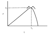
図2は、実施の形態1における電流電圧特性の一例を示す図である。図2の例では、太陽電池装置10a,10bによって発電される直流電力の電圧電流特性の一例を示す図である。縦軸に電流Iが示され、横軸に電圧Vが示される。例えば、電圧V0,電流I0において、最大電力P0が発電される。
FIG. 2 is a diagram showing an example of current-voltage characteristics in the first embodiment. In the example of FIG. 2, it is a figure which shows an example of the voltage-current characteristic of direct-current power generated with the
太陽光発電装置では、電流Iを可変にする場合、電圧Vは図2の特性に沿って移動する。よって、MPPT制御では、図2に示す電流電圧特性の曲線上を移動するように制御されることになる。太陽電池装置10bに対するMPPT制御装置120bによるMPPT制御も同様である。
In the photovoltaic power generation apparatus, when the current I is made variable, the voltage V moves along the characteristics shown in FIG. Therefore, in MPPT control, control is performed so as to move on the current-voltage characteristic curve shown in FIG. The same applies to the MPPT control by the
図3は、図2の電圧電流特性において発電される電力を示した図である。縦軸に電力Pが示され、横軸に電圧Vが示される。例えば、電圧V0において、最大電力P0が発電される。MPPT制御装置120aによるMPPT制御では、最大電力P0以上の需要がある場合に、太陽電池装置10aで発電される電力が常に最大電力P0に近づくように、図2の曲線に沿って電流、電圧を取り出す。電力需要が最大電力P0よりも少ないときには、太陽電池装置から取り出す電流Iを減らし、発電される電力が需要電力に近づくように制御される。なお、MPPT制御の方法について、細かな制御方法は問わない。例えば、電圧Vを可変してもよいし、定期的にV=0やV=V’に振るような制御を行っても良い。
FIG. 3 is a diagram showing electric power generated in the voltage-current characteristic of FIG. The vertical axis represents power P, and the horizontal axis represents voltage V. For example, the maximum power P 0 is generated at the voltage V 0 . The MPPT control by the
電力需要地域A側の二次電池装置12a,12bは、それぞれ、太陽電池装置10a,10b、発電機30、燃料電池装置32、及び太陽電池装置34によって発電された電力のうち、家屋301内の家電機器等の負荷に必要な電力を超える余剰電力を蓄電すると共に、太陽電池装置10a,10b、発電機30、燃料電池装置32、及び太陽電池装置34では賄いきれない需要が生じた場合に放電する装置である。二次電池装置12aは、充放電器122aを介して余剰電力を蓄電する。そして、二次電池装置12aは、充放電器122aを介して蓄電力を放電する。同様に、二次電池装置12bは、充放電器122bを介して余剰電力を蓄電する。そして、二次電池装置12bは、充放電器122bを介して蓄電力を放電する。
The
電力需要地域B側においても、同様に、二次電池装置22aは、充放電器222aを介して、それぞれ、太陽電池装置20a,20bによって発電された電力のうち、家屋302内の家電機器等の負荷に必要な電力を超える余剰電力を蓄電する。そして、二次電池装置22aは、充放電器222aを介して、太陽電池装置20a,20bでは賄いきれない需要が生じた場合に蓄電力を放電する。同様に、二次電池装置22bは、充放電器222bを介して余剰電力を蓄電する。そして、二次電池装置22bは、充放電器222bを介して蓄電力を放電する。
Similarly, on the power demand area B side, the secondary battery device 22a is connected to the home appliances in the
電力需要地域A側において、太陽電池装置10aで発電され、MPPT制御装置120aで受電された直流電力、太陽電池装置10bで発電され、MPPT制御装置120bで受電された直流電力、二次電池装置12aから放電され、充放電器122aを介した直流電力、或いは二次電池装置12bから放電され、充放電器122bを介した直流電力は、電力制御装置100内の直流バス101を介して、給電用直流・直流変換器134或いは/及び給電用直流・交流変換器136に供給される。或いは送電用直流・直流変換器132に供給される。給電用直流・直流変換器134で家電等の負荷に必要な電圧の電力に変換された後に家屋301内の直流電源を必要とする家電等の負荷に供給される。直流・交流変換器136で家電等の負荷に必要な交流電圧の電力に変換された後に家屋301内の交流電源を必要とする家電等の負荷に供給される。
On the power demand area A side, the DC power generated by the
電力需要地域B側において、太陽電池装置20aで発電され、MPPT制御装置220aで受電された直流電力、太陽電池装置20bで発電され、MPPT制御装置220bで受電された直流電力、二次電池装置22aから放電され、充放電器222aを介した直流電力、或いは二次電池装置22bから放電され、充放電器222bを介した直流電力は、電力制御装置200内の直流バス201を介して、給電用直流・直流変換器234或いは/及び給電用直流・交流変換器236に供給される。或いは送電用直流・直流変換器232に供給される。給電用直流・直流変換器234で家電等の負荷に必要な電圧の電力に変換された後に家屋302内の直流電源を必要とする家電等の負荷に供給され、消費される。給電用直流・交流変換器236で家電等の負荷に必要な交流電圧の電力に変換された後に家屋302内の交流電源を必要とする家電等の負荷に供給され、消費される。
On the power demand area B side, the DC power generated by the
実施の形態1では、さらに、電力制御装置100と電力制御装置200との間で直流電力を融通し合える構成となっている。具体的には、電力制御装置100内の直流バス101を介して送電用直流・直流変換器132が、送電線310を用いて直流電力を電力制御装置200に送電する。電力制御装置200内では、電力制御装置100から送電された直流電力を受電用MPPT制御装置230で受電する。受電された直流電力は、直流バス201を介して給電用直流・直流変換器234或いは/及び給電用直流・交流変換器236に供給される。給電用直流・直流変換器234で家電等の負荷に必要な電圧の電力に変換された後に家屋302内の直流電源を必要とする家電等の負荷に供給され、消費される。給電用直流・交流変換器236で家電等の負荷に必要な交流電圧の電力に変換された後に家屋302内の交流電源を必要とする家電等の負荷に供給され、消費される。或いは直流バスを介して充放電器222a,222bに供給され、二次電池装置22a,22bに蓄電される。
In the first embodiment, the DC power can be interchanged between the
逆に、電力制御装置200内の直流バス201を介して送電用直流・直流変換器232が、送電線310を用いて直流電力を電力制御装置100に送電する。電力制御装置100内では、電力制御装置200から送電された直流電力を受電用MPPT制御装置130で受電する。受電された直流電力は、直流バスを介して給電用直流・直流変換器134或いは/及び給電用直流・交流変換器136に供給される。給電用直流・直流変換器134で家電等の負荷に必要な電圧の電力に変換された後に家屋301内の直流電源を必要とする家電等の負荷に供給され、消費される。給電用直流・交流変換器136で家電等の負荷に必要な交流電圧の電力に変換された後に家屋301内の交流電源を必要とする家電等の負荷に供給され、消費される。或いは直流バスを介して充放電器122a,122bに供給され、二次電池装置12a,12bに蓄電される。
Conversely, the DC / DC converter for
なお、一方の電力制御装置から他方の電力制御装置への送電中は、自分のMPPTユニットを停止することで、かかる一方の電力制御装置からの送電電力が、かかる一方の電力制御装置の受電用MPPT制御装置に戻らないように構成する。送電用直流・直流変換器132,232は、外部から電圧が加わっても逆流しないように構成される。
During power transmission from one power control device to the other power control device, the power transmitted from the one power control device is received by the one power control device by stopping its own MPPT unit. It is configured not to return to the MPPT control device. The DC /
ここで、実施の形態1では、電力制御装置100と電力制御装置200において、外部からの直流電力の受電をいずれもMPPT制御装置で行う。そのために、外部からの直流電力の電圧電流特性を図2で示したようなMPPT制御装置で受電可能な太陽電池装置の電圧電流特性に合わせる。電力制御装置100内では、送電用直流・直流変換器132によって、電力制御装置100内の直流電力の電圧電流特性をMPPT制御装置230で受電可能な図2で示したような太陽電池装置の電圧電流特性に変換する。電力制御装置200内では、送電用直流・直流変換器232によって、電力制御装置200内の直流電力の電圧電流特性をMPPT制御装置130で受電可能な図2で示したような太陽電池装置の電圧電流特性に変換する。
Here, in the first embodiment, the
また、実施の形態1では、MPPT制御装置130が、電力制御装置200の他に、さらに、発電機30、燃料電池装置32、及び太陽電池装置34からも受電する。受電するための電力を送電する相手は、切替器50によって回路を切り替えればよい。太陽電池装置34では、もともと、図2で示したような太陽電池装置の電圧電流特性をもった電力が出力されるのでMPPT制御装置130で受電可能である。しかしながら、発電機30、及び燃料電池装置32といった太陽電池装置とは異なる発電装置では、出力される電力の電圧電流特性が太陽電池装置の電圧電流特性とは異なる。よって、そのままでは、MPPT制御装置130で受電することはできない。そこで、実施の形態1では、発電機30の出力側に、太陽電池によって発電される直流電力の電圧電流特性と同等の電圧電流特性に変換し、変換された直流電力を送電する送電装置40aを配置する。同様に、燃料電池装置32の出力側に、太陽電池によって発電される直流電力の電圧電流特性と同等の電圧電流特性に変換し、変換された直流電力を送電する送電装置40bを配置する。
In the first embodiment, the
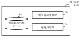
図4は、実施の形態1の送電装置の内部構成の一例を示す構成図である。図4において、送電用直流・直流変換器132(送電装置の一例)内には、電圧電流変換部60、記憶装置62、及び送電処理部64が配置される。記憶装置62には、電圧電流特性データが記憶される。同様に、送電用直流・直流変換器232(送電装置の一例)内には、電圧電流変換部60、記憶装置62、及び送電処理部64が配置される。記憶装置62には、電圧電流特性データが記憶される。同様に、送電装置40a,40b内には、それぞれ、電圧電流変換部60、記憶装置62、及び送電処理部64が配置される。電圧電流特性データは、送電する電力の大きさに応じて設定されればよい。
FIG. 4 is a configuration diagram illustrating an example of an internal configuration of the power transmission device according to the first embodiment. In FIG. 4, a voltage /
例えば、太陽電池装置10a,10b,20a,20b,34には、それぞれ最大出力が設定されている。そして、電圧電流特性もそれぞれのそれぞれ最大出力に応じて装置毎に存在する。同じ機種の同じ型式の太陽電池装置を用いれば、同じ電圧電流特性になるが、日射強度等の条件が異なれば、それぞれ異なる電圧電流特性の曲線になる。しかしながら、太陽電池装置10a,10b,20a,20b,34では、いずれも電圧電流特性が図2に示すように、電圧が大きくなるに従い電流が徐々に小さくなり、最大電力P0を超えるあたりから電流の減少が大きくなるが、全体としてなだらかな曲線を描く特徴がある。MPPT制御装置では、図2に示すように、電圧が大きくなるに従い電流が徐々に小さくなり、最大電力P0を超えるあたりから電流の減少が大きくなるが、全体としてなだらかな曲線を描く特徴の電圧電流特性であれば、追従することができる。
For example, the maximum output is set in each of the
そこで、実施の形態1では、発電機30の最大出力に応じて、図2に示すように、電圧が大きくなるに従い電流が徐々に小さくなり、最大電力P0(例えば、1000W)を超えるあたりから電流の減少が大きくなるが、全体としてなだらかな曲線を描く特徴をもった電圧電流特性データ(1)を予め作成しておく。そして、電圧電流特性データ(1)を送電装置40a内の記憶装置62に格納しておく。同様に、燃料電池装置32の最大出力に応じて、図2に示すように、電圧が大きくなるに従い電流が徐々に小さくなり、最大電力P0(例えば、700W)を超えるあたりから電流の減少が大きくなるが、全体としてなだらかな曲線を描く特徴をもった電圧電流特性データ(2)を予め作成しておく。そして、電圧電流特性データ(2)を送電装置40b内の記憶装置62に格納しておく。
Therefore, in the first embodiment, as shown in FIG. 2, the current gradually decreases as the voltage increases, depending on the maximum output of the
送電装置40a、40b内の記憶装置62に格納する電圧電流特性データは、例えば図2のような曲線である。その電圧電流特性データは、受電用MPPT130、230の入力定格より決定する。受電用MPPT130、230の入力定格には最大入力電圧Vmaxと最大入力電流Imax、および、最大入力電力Pmaxの3つの要素がある。図2の曲線において、電流I=0時の電圧がVoc、電圧V=0の時の電流がIscの場合、Voc≦Vmax、Isc≦Imaxである必要がある。また、送電する最大電力P0は、P0≦Pmaxである必要がある。送電する最大電力P0の時の電圧をV0、電流をI0とすると、P0=V0×I0である。この時、V0<Vmax、I0<Imaxであり、且つ、P0≦Pmaxとなる点を任意に決定する。そして、点P0が図2のような曲線上に存在し、その曲線に沿って電圧と電流が変化したときの電力が図3のように最大点を持ち、且つ、その最大点がP0となる曲線を決定すればよい。そして、作成された電圧電流特性データを記憶装置62に格納すれば良い。このように決定した図2のような曲線について、例えば電流Iの方向に曲線を等比変形することにより、送電する電力P0の大きさを任意に変化させた曲線を得ることが出来る。
The voltage / current characteristic data stored in the storage device 62 in the power transmission devices 40a and 40b is, for example, a curve as shown in FIG. The voltage / current characteristic data is determined from the input ratings of the
図5は、実施の形態1における電圧電流特性データの一例を示す図である。図5では、送電用直流・直流変換器132,232内の記憶装置62に格納される電圧電流特性データの一例を示す。送電用直流・直流変換器132,232では、電力制御装置200,100に送電する電力の複数の最大電力を予め設定しておく。図5に示すように、例えば、3つの最大電力P0,P’0,P”0を設定しておく。例えば、1500W、1000W、500Wに設定しておく。それぞれの最大電力に応じて、図5に示すように、電圧が大きくなるに従い電流が徐々に小さくなり、最大電力を超えるあたりから電流の減少が大きくなるが、全体としてなだらかな曲線を描く特徴の電圧電流特性データ(3)(4)(5)を設定しておく。言い換えれば、電力制御装置100,200間では、設定された複数の最大電力のうちその時に受電する側が希望する1つの最大電力の電力を送電する。但し、これに限るものではない。少なくとも1つの電圧電流特性データを設定しておけばよい。電力融通の処理の仕方については後述する。
FIG. 5 is a diagram illustrating an example of voltage-current characteristic data according to the first embodiment. FIG. 5 shows an example of voltage-current characteristic data stored in the storage device 62 in the DC /
図6は、実施の形態1における電力システムの制御方法の要部工程を示すフローチャート図である。図6において、実施の形態1における電力システムの制御方法は、発電工程(S102)と、電圧電流変換工程(S104)と、送電工程(S106)と、受電工程(S108)という一例の工程を実施する。 FIG. 6 is a flowchart showing main steps of the power system control method according to the first embodiment. In FIG. 6, the power system control method according to the first embodiment performs an example of a power generation process (S102), a voltage / current conversion process (S104), a power transmission process (S106), and a power reception process (S108). To do.
ここでは、発電機30、或いは燃料電池装置32で発電された電力を電力制御装置100で受電するまでの各工程について説明する。まず、発電機30、燃料電池装置32、及び太陽電池装置34のうち、発電に用いる装置を選択し、選択された装置の伝送経路を切替器50によって受電用MPPT制御装置130に接続する。
Here, each process until the electric power generated by the
発電工程(S102)として、発電機30の伝送経路が受電用MPPT制御装置130に接続される場合、発電機30は、電力需要に応じて自己の最大電力の範囲内で発電を行う。或いは、燃料電池装置32の伝送経路が受電用MPPT制御装置130に接続される場合、燃料電池装置32は、電力需要に応じて自己の最大電力の範囲内で発電を行う。或いは、太陽電池装置34の伝送経路が受電用MPPT制御装置130に接続される場合、太陽電池装置34は、電力需要に応じて自己の最大電力の範囲内で発電を行う。ここで、各発電装置は、自己の最大電力で発電する方が、より発電効率が高い。よって、できるだけ自己の最大電力で発電するように制御することが望ましい。
As a power generation step (S102), when the transmission path of the
電圧電流変換工程(S104)として、発電機30の伝送経路が受電用MPPT制御装置130に接続に接続される場合、送電装置40a内の電圧電流変換部60は、発電機30によって発電された直流電力を入力し、直流電力の電圧電流特性を、太陽電池装置によって発電される直流電力の電圧電流特性と同様の特徴をもった電圧電流特性に変換する。その際、電圧電流変換部60は、送電装置40a内の記憶装置62に格納された電圧電流特性データを読み出し、かかる電圧電流特性データが示す曲線に沿って直流電力に応じた電圧と電流に変換する。
In the voltage-current conversion step (S104), when the transmission path of the
或いは、燃料電池装置32の伝送経路が受電用MPPT制御装置130に接続に接続される場合、送電装置40b内の電圧電流変換部60は、発電機30によって発電された直流電力を入力し、直流電力の電圧電流特性を、太陽電池装置によって発電される直流電力の電圧電流特性と同様の特徴をもった電圧電流特性に変換する。その際、電圧電流変換部60は、送電装置40b内の記憶装置62に格納された電圧電流特性データを読み出し、かかる電圧電流特性データが示す曲線に沿って直流電力に応じた電圧と電流に変換する。
Alternatively, when the transmission path of the
太陽電池装置34の伝送経路が受電用MPPT制御装置130に接続に接続される場合、電圧電流変換工程(S104)は省略される。
When the transmission path of the
送電工程(S106)として、発電機30の伝送経路が受電用MPPT制御装置130に接続に接続される場合、送電装置40a内の送電処理部64は、変換された電圧と電流をもった電力を受電用MPPT制御装置130に送電する。
As the power transmission step (S106), when the transmission path of the
或いは、燃料電池装置32の伝送経路が受電用のMPPT制御装置130に接続に接続される場合、送電装置40b内の送電処理部64は、変換された電圧と電流をもった電力を受電用MPPT制御装置130に送電する。
Alternatively, when the transmission path of the
或いは、太陽電池装置34の伝送経路が受電用MPPT制御装置130に接続に接続される場合、太陽電池装置34によって発電された直流電力が受電用MPPT制御装置130に送電される。
Alternatively, when the transmission path of the
受電工程(S108)として、受電用のMPPT制御装置130(制御装置)は、太陽電池装置によって発電された直流電力の電圧電流特性と同様の特徴をもった電圧電流特性に合わせた、発電機30、燃料電池装置32、及び太陽電池装置34といった複数の発電装置によって発電された直流電力の1つを、MPPT制御を実行することによって受電する。すなわち、MPPT制御装置130は、太陽電池装置用であって、他の発電装置にも兼用できる。受電された直流電力は直流バス101に出力される。
As the power receiving step (S108), the MPPT control device 130 (control device) for receiving power has a
図6のフローチャートは、電力制御装置100,200間での電力融通についても当てはまる。まず、電力制御装置100から電力制御装置200に電力を送電する場合について説明する。
The flowchart in FIG. 6 also applies to power interchange between the
まず、発電工程(S102)として、太陽電池装置10a,10b、発電機30、燃料電池装置32、或いは太陽電池装置34は、電力需要に応じて自己の最大電力の範囲内で発電を行う。或いは、二次電池装置12a,12bは、電力需要に応じて自己の充電電力の範囲内で放電を行う。
First, as a power generation step (S102), the
電圧電流変換工程(S104)として、太陽電池装置10a,10bによって発電された直流電力は、MPPT制御装置120a,120bによって制御され、電力制御装置100内の直流バスを介して送電用直流・直流変換器132に供給される。そして、送電用直流・直流変換器132内の電圧電流変換部60は、直流電力の電圧電流特性を、太陽電池装置によって発電される直流電力の電圧電流特性と同様の特徴をもった電圧電流特性に変換する。その際、電圧電流変換部60は、送電用直流・直流変換器132内の記憶装置62に格納された複数の電圧電流特性データのうち受電側が希望する1つを読み出し、かかる電圧電流特性データが示す曲線に沿って直流電力に応じた電圧と電流に変換する。
In the voltage-current conversion step (S104), the DC power generated by the
また、発電機30、燃料電池装置32、或いは太陽電池装置34によって発電された直流電力は、受電用のMPPT制御装置130によって制御され、電力制御装置100内の直流バスを介して送電用直流・直流変換器132に供給される。そして、送電用直流・直流変換器132内の電圧電流変換部60は、直流電力の電圧電流特性を、太陽電池装置によって発電される直流電力の電圧電流特性と同様の特徴をもった電圧電流特性に変換する。その際、電圧電流変換部60は、送電用直流・直流変換器132内の記憶装置62に格納された複数の電圧電流特性データのうち受電側が希望する1つを読み出し、かかる電圧電流特性データが示す曲線に沿って直流電力に応じた電圧と電流に変換する。
In addition, the DC power generated by the
また、二次電池装置12a,12bから放電された直流電力は、充放電器122a,122bによって制御され、電力制御装置100内の直流バスを介して送電用直流・直流変換器132に供給される。そして、送電用直流・直流変換器132内の電圧電流変換部60は、直流電力の電圧電流特性を、太陽電池装置によって発電される直流電力の電圧電流特性と同様の特徴をもった電圧電流特性に変換する。その際、電圧電流変換部60は、送電用直流・直流変換器132内の記憶装置62に格納された複数の電圧電流特性データのうち受電側が希望する1つを読み出し、かかる電圧電流特性データが示す曲線に沿って直流電力に応じた電圧と電流に変換する。
The DC power discharged from the
或いは、これらの直流電力を合わせて電力制御装置100内の直流バスを介して送電用直流・直流変換器132に供給されてもよい。そして、送電用直流・直流変換器132内の電圧電流変換部60は、太陽電池装置10a,10bと、発電機30、燃料電池装置32、或いは太陽電池装置34との複数の発電装置によって発電された直流電力および二次電池装置12a,12bから放電された直流電力といった複数の直流電力をまとめた直流電力の電圧電流特性を、太陽電池によって発電される直流電力の電圧電流特性と同様の特徴をもった電圧電流特性に変換する。
Alternatively, these DC powers may be combined and supplied to the power transmission DC /
送電工程(S106)として、電力需要地域A(第1の電力需要地域)に配置された送電用直流・直流変換器132内の送電処理部64は、変換された電圧と電流をもった電力を受電用のMPPT制御装置230に送電する。
As the power transmission process (S106), the power
受電工程(S108)として、電力需要地域Aとは異なる電力需要地域B(第2の電力需要地域)に配置された受電用のMPPT制御装置230(制御装置)は、太陽電池装置によって発電された直流電力の電圧電流特性と同様の特徴をもった電圧電流特性に合わせた、太陽電池装置10a,10b、発電機30、燃料電池装置32、及び太陽電池装置34といった複数の発電装置によって発電された直流電力と二次電池装置12a,12bから放電された直流電力との1つ、或いは2以上が合成された直流電力を、電力需要地域Bの電力需要に応じてMPPT制御を実行することによって受電する。受電された直流電力は直流バス201に出力される。
As the power receiving step (S108), the MPPT control device 230 (control device) for power reception disposed in the power demand region B (second power demand region) different from the power demand region A was generated by the solar cell device. Power was generated by a plurality of power generation devices such as
次に、電力制御装置200から電力制御装置100に電力を送電する場合について説明する。かかる場合には、切替器50の接続を送電用直流・直流変換器232と受電用のMPPT制御装置130とが繋がるように切り替える。
Next, a case where power is transmitted from the
まず、発電工程(S102)として、太陽電池装置20a,20bは、電力需要に応じて自己の最大電力の範囲内で発電を行う。或いは、二次電池装置22a,22bは、電力需要に応じて自己の充電電力の範囲内で放電を行う。
First, as a power generation step (S102), the
電圧電流変換工程(S104)として、太陽電池装置20a,20bによって発電された直流電力は、MPPT制御装置220a,220bによって制御され、電力制御装置200内の直流バスを介して送電用直流・直流変換器232に供給される。そして、送電用直流・直流変換器232内の電圧電流変換部60は、直流電力の電圧電流特性を、太陽電池装置によって発電される直流電力の電圧電流特性と同様の特徴をもった電圧電流特性に変換する。その際、電圧電流変換部60は、送電用直流・直流変換器232内の記憶装置62に格納された複数の電圧電流特性データのうち受電側が希望する1つを読み出し、かかる電圧電流特性データが示す曲線に沿って直流電力に応じた電圧と電流に変換する。
In the voltage-current conversion step (S104), the DC power generated by the
また、二次電池装置22a,22bから放電された直流電力は、充放電器222a,222bによって制御され、電力制御装置200内の直流バスを介して送電用直流・直流変換器232に供給される。そして、送電用直流・直流変換器232内の電圧電流変換部60は、直流電力の電圧電流特性を、太陽電池装置によって発電される直流電力の電圧電流特性と同様の特徴をもった電圧電流特性に変換する。その際、電圧電流変換部60は、送電用直流・直流変換器232内の記憶装置62に格納された複数の電圧電流特性データのうち受電側が希望する1つを読み出し、かかる電圧電流特性データが示す曲線に沿って直流電力に応じた電圧と電流に変換する。
Further, the DC power discharged from the
或いは、これらの直流電力を合わせて電力制御装置200内の直流バスを介して送電用直流・直流変換器232に供給されてもよい。そして、送電用直流・直流変換器232内の電圧電流変換部60は、太陽電池装置20a,20bとの複数の発電装置によって発電された直流電力および二次電池装置22a,22bから放電された直流電力といった複数の直流電力をまとめた直流電力の電圧電流特性を、太陽電池によって発電される直流電力の電圧電流特性と同様の特徴をもった電圧電流特性に変換する。
Alternatively, these DC powers may be combined and supplied to the power transmission DC /
送電工程(S106)として、電力需要地域B(第2の電力需要地域)に配置された送電用直流・直流変換器232内の送電処理部64は、変換された電圧と電流をもった電力を受電用のMPPT制御装置130に送電する。
As the power transmission process (S106), the power
受電工程(S108)として、電力需要地域Bとは異なる電力需要地域A(第1の電力需要地域)に配置された受電用のMPPT制御装置130(制御装置)は、送電用直流・直流変換器232から送電された直流電力を、電力需要地域Aの電力需要に応じてMPPT制御を実行することによって受電する。受電された直流電力は直流バス101に出力される。
As the power receiving step (S108), the MPPT control device 130 (control device) for receiving power disposed in the power demand region A (first power demand region) different from the power demand region B is a DC / DC converter for power transmission. The DC power transmitted from H.232 is received by executing MPPT control according to the power demand in the power demand area A. The received DC power is output to the
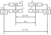
図7は、実施の形態1における電力融通方法の一例のフローチャート図である。図7では、例えば、電力制御装置100から電力制御装置200に電力を送電する場合について示している。電力制御装置200から電力制御装置100に電力を送電する場合、図7の矢印の向きがそれぞれ逆になればよい。
FIG. 7 is a flowchart of an example of the power interchange method in the first embodiment. FIG. 7 shows a case where power is transmitted from the
まず、管理部238は、通信制御部240を介して、電力制御装置100に対して、電力供給を要求する。その際、設定されている複数の最大電力P0,P’0,P”0のうち、希望する最大電力を示す情報を合わせて送信する。電力制御装置100内では、管理部138が、通信制御部140を介して、電力制御装置200からの電力供給の要求と希望する最大電力を示す情報とを受信する。
First, the
電力制御装置100内では、管理部138が、通信制御部140を介して、電力制御装置200に、承認したことを示す情報を送信する。
In the
送電用直流・直流変換器132内の送電処理部64は、希望された最大電力に対応する電圧電流特性データに沿って変換された電圧と電流をもった電力を受電用のMPPT制御装置230に送電する。
The power
以上により、電力需要地域A(第1の電力需要地域)に配置された電力制御装置100から、電力需要地域Aとは異なる電力需要地域B(第2の電力需要地域)に配置された電力制御装置200に電力を融通できる。また、実施の形態1では、直流電力を用いるので、送電しない間は、送電用直流・直流変換器132と受電用のMPPT制御装置230との間の送電線に電圧は印加されない。そのため、常に電圧が印加されている場合に比べて電力損失を抑制できる。
As described above, the power control arranged in the power demand area B (second power demand area) different from the power demand area A from the
以上のように実施の形態1によれば、太陽電池装置、燃料電池装置、及びその他の発電装置から発電された電力をいずれもMPPT制御装置で受電することができる。このように、実施の形態1では、MPPT制御装置130は、複数の発電装置によって発電された複数の直流電力のうち選択された1つを受電し、最大電力点追従(MPPT)制御を実行できる。よって、種類の異なる複数の発電装置から発電された電力を利用できると共に、他の需要家へと融通することができる。
As described above, according to the first embodiment, all the electric power generated from the solar cell device, the fuel cell device, and other power generation devices can be received by the MPPT control device. As described above, in the first embodiment, the
また、実施の形態1では、燃料電池や発電機等の種々の電源の直流出力特性を太陽電池の電圧電流特性と同じにすることで、1台のMPPTユニットに複数の電源を切り替えて接続することを可能にする。また、電力システムに送電装置を追加するだけで、電力制御装置同士の電力融通を可能にする。また、MPPTユニットの兼用により電力システムの部品が削減でき、電力システムの小型化およびコスト低減ができる。さらに、既存の太陽光発電システムにも直流で送電が可能になる。 In the first embodiment, the DC output characteristics of various power sources such as a fuel cell and a generator are made the same as the voltage-current characteristics of the solar cell, so that a plurality of power sources are switched and connected to one MPPT unit. Make it possible. Moreover, the power interchange between the power control devices is enabled only by adding the power transmission device to the power system. Further, the power system components can be reduced by sharing the MPPT unit, and the power system can be reduced in size and cost. In addition, direct current power can be transmitted to the existing solar power generation system.
また、実施の形態1では、交流の系統電力を用いずに、発電装置が発電する直流電力でシステムの系が閉じられているので、発電された電力は直流のまま送電および受電を行う。発電された電力は直流のまま送電および受電を行うので、交流電力に変換する際の損失を抑えることができる。 In the first embodiment, the system system is closed with DC power generated by the power generation device without using AC system power, and thus the generated power is transmitted and received while being DC. Since the generated electric power is transmitted and received with a direct current, loss when converted into alternating current power can be suppressed.
実施の形態2.
実施の形態1では、発電機30、燃料電池装置32、及び太陽電池装置34を切替器50で切り替えて受電したが、これに限るものではない。実施の形態2では、切替器50を用いない構成について説明する。
In the first embodiment, the
図8は、実施の形態2における電力システムの構成の一例の一部を示す構成図である。図8において、発電機30と送電装置40aの組み合わせ、燃料電池装置32と送電装置40bの組み合わせ、その他、風力発電機や水力発電機、電気自動車の蓄電池などの直流電源装置36と送電装置40cの組み合わせ、及び太陽電池装置10aが並列に、それぞれ対応するダイオード41a〜41dを介してMPPT制御装置120aに接続されている点、切替器50、及び太陽電池装置34が省略されている点、受電用のMPPT制御装置130は、送電用直流・直流変換器232に切替器50無で接続されている点以外は、図1と同様である。図8では、切替器50を用いていないため、いずれかの発電装置で発電された直流電力が他の発電装置に逆流しないように、発電機30と送電装置40aの組み合わせ、燃料電池装置32と送電装置40bの組み合わせ、その他の直流電源装置36と送電装置40cの組み合わせ、及び太陽電池装置10aの出力側には、それぞれ対応するダイオード41a〜41dが接続されている。図8の構成の場合、並列に配置された、発電機30と送電装置40aの組み合わせ、燃料電池装置32と送電装置40bの組み合わせ、その他の直流電源装置36と送電装置40cの組み合わせ、及び太陽電池装置10aの切り替えは、それぞれの発電装置がもつ電源スイッチを利用すればよい。使用する発電装置だけ電源スイッチをONにし、残りはOFFにしておけばよい。或いは、一部又はすべての発電装置の電源スイッチをONにしておいても構わない。かかる場合、負荷が1つの発電装置の最大発電量を超える場合でも並列運転により補うことができる。このように、実施の形態2では、MPPT制御装置120aは、複数の発電装置によって発電された複数の直流電力の1つ、一部、或いは全部を、最大電力点追従(MPPT)制御を実行することによって受電できる。
FIG. 8 is a configuration diagram illustrating a part of an example of the configuration of the power system according to the second embodiment. In FIG. 8, the combination of the
また、燃料電池装置32に使用する燃料電池として、固体酸化物燃料電池(SOFC:Solid Oxide Fuel Cell)が用いられると好適である。SOFCを使用することで燃料から電力への変換効率を高めることができる。但し、これに限るものではない。その他の燃料電池を用いても構わない。例えば、固体高分子形燃料電池(PEFC)、りん酸形燃料電池(PAFC)、溶融炭酸塩形燃料電池(MCFC)、アルカリ電解質形燃料電池(AFC)、直接形燃料電池(DFC)、或いはバイオ燃料電池、等を用いてもよい。
Further, it is preferable that a solid oxide fuel cell (SOFC) is used as the fuel cell used for the
以上、具体例を参照しつつ実施の形態について説明した。しかし、本発明は、これらの具体例に限定されるものではない。 The embodiments have been described above with reference to specific examples. However, the present invention is not limited to these specific examples.
また、装置構成や制御手法等、本発明の説明に直接必要しない部分等については記載を省略したが、必要とされる装置構成や制御手法を適宜選択して用いることができる。 In addition, although descriptions are omitted for parts and the like that are not directly required for the description of the present invention, such as a device configuration and a control method, a required device configuration and a control method can be appropriately selected and used.
その他、本発明の要素を具備し、当業者が適宜設計変更しうる全ての電力システム及び電力システムの制御方法は、本発明の範囲に包含される。 In addition, all power systems that include elements of the present invention and that can be appropriately modified by those skilled in the art and methods for controlling the power systems are included in the scope of the present invention.
10,20 太陽電池装置
12,22 二次電池装置
30 発電機
32 燃料電池装置
34 太陽電池装置
36 直流電源
40 送電装置
41 ダイオード
50 切替器
60 電圧電流変換部
62 記憶装置
64 送電処理部
100,200 電力制御装置
101,201 DCバス
120,220 MPPT制御装置
122,222 充放電器
130,230 MPPT制御装置
132,232 送電用直流・直流変換器
134,234 給電用直流・直流変換器
136,236 給電用直流・交流変換器
138,238 管理部
140,240 通信制御部
301,302 家屋
310 送電線
500 電力システム
DESCRIPTION OF SYMBOLS 10,20 Solar cell apparatus 12,22
Claims (7)
前記1つまたは複数の発電装置によって発電された直流電力のうちの少なくとも1つの直流電力の電圧電流特性を、前記太陽電池によって発電される直流電力の電圧電流特性と同様の特徴をもった電圧電流特性に変換し、変換された直流電力を送電する送電装置と、
を備えたことを特徴とする電力システム。 One or more power generation devices different from solar cell devices that generate power using sunlight; and
Voltage current characteristics of at least one DC power among DC power generated by the one or more power generators is similar to the voltage current characteristics of DC power generated by the solar cell. A power transmission device that converts the characteristic into power and transmits the converted DC power;
An electric power system comprising:
前記送電装置から送電された直流電力を、最大電力点追従(MPPT)制御を実行することにより受電する受電装置と、
を備えたことを特徴とする電力システム。 A direct current generated by the solar cell device is obtained by using a voltage-current characteristic of at least one direct current power among direct current power generated by one or more power generation devices different from the solar cell device that generates power using sunlight. A power transmission device that converts the voltage-current characteristics having the same characteristics as the voltage-current characteristics of power and transmits the converted DC power;
A power receiving device that receives DC power transmitted from the power transmitting device by executing maximum power point tracking (MPPT) control;
An electric power system comprising:
前記太陽光発電装置によって発電された直流電力を受電する前記装置機構が、前記受電装置を兼ねることを特徴とする請求項2記載の電力システム。 The power system receives direct-current power generated by a solar cell device that generates power using sunlight using a device mechanism that receives power by executing MPPT control,
The power system according to claim 2, wherein the device mechanism that receives DC power generated by the solar power generation device also serves as the power receiving device.
前記第1の電力需要地域とは異なる第2の電力需要地域に配置された、前記第1の電力制御装置と同様の送電装置と受電装置とを有する第2の電力制御装置と、
をさらに備え、
前記第1の電力制御装置と前記第2の電力制御装置とを接続し、互いに電力融通を行うことを特徴とする請求項3又は4記載の電力システム。 A first power control device disposed in a first power demand area and having the power transmission device and the power reception device;
A second power control device having a power transmission device and a power reception device similar to the first power control device, disposed in a second power demand region different from the first power demand region;
Further comprising
5. The power system according to claim 3, wherein the first power control device and the second power control device are connected to perform power interchange with each other.
前記太陽電池装置とは異なる、1つまたは複数の発電装置と、
前記1つまたは複数の発電装置によって発電された直流電力のうちの少なくとも1つの直流電力の電圧電流特性を、前記太陽電池によって発電される直流電力の電圧電流特性と同様の特徴をもった電圧電流特性に変換し、変換された直流電力を送電する送電装置と、
前記太陽電池によって発電される直流電力の電圧電流特性と同様の特徴をもった電圧電流特性に合わせた、前記1つまたは複数の発電装置によって発電された直流電力を、最大電力点追従(MPPT)制御を実行することで受電する受電装置と、
を備えたことを特徴とする電力システム。 A power system comprising: a solar cell device that generates power using sunlight; and a power supply device that converts power from the solar cell device and feeds direct or alternating current power to a load,
One or more power generation devices different from the solar cell device;
Voltage current characteristics of at least one DC power among DC power generated by the one or more power generators is similar to the voltage current characteristics of DC power generated by the solar cell. A power transmission device that converts the characteristic into power and transmits the converted DC power;
The DC power generated by the one or more power generators in accordance with the voltage-current characteristic having the same characteristics as the voltage-current characteristic of the DC power generated by the solar cell is converted into maximum power point tracking (MPPT). A power receiving device that receives power by executing control;
An electric power system comprising:
前記給電装置は、前記蓄電池装置からの電力を変換し、前記負荷に直流または交流の電力を給電することを特徴とする請求項5記載の電力システム。 A storage battery device that stores direct-current power generated by the solar cell device;
The power system according to claim 5, wherein the power feeding device converts power from the storage battery device and feeds DC or AC power to the load.
最大電力点追従(MPPT)制御を実行することにより直流電力を受電する受電装置に、変換された直流電力を送電する工程と、
を備えたことを特徴とする直流送電方法。 A direct current generated by the solar cell device is obtained by using a voltage-current characteristic of at least one direct current power among direct current power generated by one or more power generation devices different from the solar cell device that generates power using sunlight. A step of converting to a voltage-current characteristic having characteristics similar to the voltage-current characteristic of power;
Transmitting the converted DC power to a power receiving device that receives DC power by executing maximum power point tracking (MPPT) control;
A direct-current power transmission method comprising:
Priority Applications (1)
| Application Number | Priority Date | Filing Date | Title |
|---|---|---|---|
| JP2014069855A JP2015192566A (en) | 2014-03-28 | 2014-03-28 | Power system and dc power transmission method |
Applications Claiming Priority (1)
| Application Number | Priority Date | Filing Date | Title |
|---|---|---|---|
| JP2014069855A JP2015192566A (en) | 2014-03-28 | 2014-03-28 | Power system and dc power transmission method |
Publications (1)
| Publication Number | Publication Date |
|---|---|
| JP2015192566A true JP2015192566A (en) | 2015-11-02 |
Family
ID=54426677
Family Applications (1)
| Application Number | Title | Priority Date | Filing Date |
|---|---|---|---|
| JP2014069855A Pending JP2015192566A (en) | 2014-03-28 | 2014-03-28 | Power system and dc power transmission method |
Country Status (1)
| Country | Link |
|---|---|
| JP (1) | JP2015192566A (en) |
Cited By (11)
| Publication number | Priority date | Publication date | Assignee | Title |
|---|---|---|---|---|
| JP2017118764A (en) * | 2015-12-25 | 2017-06-29 | 株式会社Lixil | Output control device for wind power generation |
| JP2017192191A (en) * | 2016-04-12 | 2017-10-19 | サンケン電気株式会社 | Dc/dc converter and solar power generation system |
| JP2019083635A (en) * | 2017-10-31 | 2019-05-30 | サンケン電気株式会社 | Power storage system |
| JP2019097280A (en) * | 2017-11-21 | 2019-06-20 | パナソニックIpマネジメント株式会社 | Power system |
| WO2020158006A1 (en) * | 2019-01-30 | 2020-08-06 | パナソニックIpマネジメント株式会社 | Dc power supply system and power system |
| JP2020123135A (en) * | 2019-01-30 | 2020-08-13 | パナソニックIpマネジメント株式会社 | Electric power system |
| JP2020137305A (en) * | 2019-02-21 | 2020-08-31 | パナソニックIpマネジメント株式会社 | Power system |
| JP2020137154A (en) * | 2019-02-13 | 2020-08-31 | パナソニックIpマネジメント株式会社 | Power system and DC power supply system |
| JP2020137304A (en) * | 2019-02-21 | 2020-08-31 | パナソニックIpマネジメント株式会社 | Power system and DC power supply system |
| JP2020188603A (en) * | 2019-05-15 | 2020-11-19 | パナソニックIpマネジメント株式会社 | Power system |
| JP2021129460A (en) * | 2020-02-14 | 2021-09-02 | パナソニックIpマネジメント株式会社 | Electric power system and power extraction method |
-
2014
- 2014-03-28 JP JP2014069855A patent/JP2015192566A/en active Pending
Cited By (16)
| Publication number | Priority date | Publication date | Assignee | Title |
|---|---|---|---|---|
| JP2017118764A (en) * | 2015-12-25 | 2017-06-29 | 株式会社Lixil | Output control device for wind power generation |
| JP2017192191A (en) * | 2016-04-12 | 2017-10-19 | サンケン電気株式会社 | Dc/dc converter and solar power generation system |
| JP7071816B2 (en) | 2017-10-31 | 2022-05-19 | 株式会社Gsユアサ インフラシステムズ | Power storage system |
| JP2019083635A (en) * | 2017-10-31 | 2019-05-30 | サンケン電気株式会社 | Power storage system |
| JP2019097280A (en) * | 2017-11-21 | 2019-06-20 | パナソニックIpマネジメント株式会社 | Power system |
| WO2020158006A1 (en) * | 2019-01-30 | 2020-08-06 | パナソニックIpマネジメント株式会社 | Dc power supply system and power system |
| JP7038309B2 (en) | 2019-01-30 | 2022-03-18 | パナソニックIpマネジメント株式会社 | Power system |
| JP2020123135A (en) * | 2019-01-30 | 2020-08-13 | パナソニックIpマネジメント株式会社 | Electric power system |
| JP2020137154A (en) * | 2019-02-13 | 2020-08-31 | パナソニックIpマネジメント株式会社 | Power system and DC power supply system |
| JP7138306B2 (en) | 2019-02-13 | 2022-09-16 | パナソニックIpマネジメント株式会社 | Power system and DC power supply system |
| JP2020137305A (en) * | 2019-02-21 | 2020-08-31 | パナソニックIpマネジメント株式会社 | Power system |
| JP2020137304A (en) * | 2019-02-21 | 2020-08-31 | パナソニックIpマネジメント株式会社 | Power system and DC power supply system |
| JP2020188603A (en) * | 2019-05-15 | 2020-11-19 | パナソニックIpマネジメント株式会社 | Power system |
| JP7174897B2 (en) | 2019-05-15 | 2022-11-18 | パナソニックIpマネジメント株式会社 | power system |
| JP2021129460A (en) * | 2020-02-14 | 2021-09-02 | パナソニックIpマネジメント株式会社 | Electric power system and power extraction method |
| JP7352881B2 (en) | 2020-02-14 | 2023-09-29 | パナソニックIpマネジメント株式会社 | Power system and power extraction method |
Similar Documents
| Publication | Publication Date | Title |
|---|---|---|
| JP2015192566A (en) | Power system and dc power transmission method | |
| US10756544B2 (en) | Energy storage system and management method thereof | |
| JP5327407B2 (en) | Storage battery system and control method thereof | |
| US20110106322A1 (en) | Network connection manner of microgrid energy storage backup power source, and method for dispatching the same | |
| JP5960958B2 (en) | Power management system | |
| US20160329744A1 (en) | Power control device and power control method | |
| US20120217800A1 (en) | Solar power systems optimized for use in communications networks | |
| JP6689093B2 (en) | Grid-connected power conditioner and distributed power supply network | |
| US8420240B2 (en) | Method for controlling sodium-sulfur batteries | |
| JP5475387B2 (en) | Power supply optimization device for power supply system | |
| CN112736910A (en) | Micro-grid system, black start method and device thereof, and computer readable storage medium | |
| US11277008B2 (en) | Energy storage system | |
| EP2330677B1 (en) | Method for controlling sodium-sulfur battery | |
| KR101626911B1 (en) | Power control system and method for plural energy storage devices | |
| US8525369B2 (en) | Method and device for optimizing the use of solar electrical power | |
| KR20150085227A (en) | The control device and method for Energy Storage System | |
| JP2016032379A (en) | Power supply system | |
| KR102463396B1 (en) | Energy storage system | |
| US10320327B1 (en) | Power storage power conditioner | |
| KR102053812B1 (en) | Method and system for controlling power conversion system connected to hybrid battery | |
| Jawad et al. | Bi-Directional Nano Grid Design for Organizations with Plug-In Electric Vehicle Charging at Workplace | |
| JP6055968B2 (en) | Power system | |
| KR102333046B1 (en) | Charge-discharge amount control device of energy storage system and control method | |
| JP2017195739A (en) | Power supply device, power supply system, and micro grid | |
| Lozanov et al. | Simulation Modeling of Microgrid with Battery Energy Storage and Fuel Cells Integration |