JP2014502407A - Cleaning method and cleaning system for sheet-like or plate-like object - Google Patents
Cleaning method and cleaning system for sheet-like or plate-like object Download PDFInfo
- Publication number
- JP2014502407A JP2014502407A JP2013539156A JP2013539156A JP2014502407A JP 2014502407 A JP2014502407 A JP 2014502407A JP 2013539156 A JP2013539156 A JP 2013539156A JP 2013539156 A JP2013539156 A JP 2013539156A JP 2014502407 A JP2014502407 A JP 2014502407A
- Authority
- JP
- Japan
- Prior art keywords
- transport belt
- brush
- cleaning device
- cleaning
- electrode
- Prior art date
- Legal status (The legal status is an assumption and is not a legal conclusion. Google has not performed a legal analysis and makes no representation as to the accuracy of the status listed.)
- Pending
Links
- 238000004140 cleaning Methods 0.000 title claims abstract description 144
- 238000000034 method Methods 0.000 title claims description 39
- 238000012983 electrochemical energy storage Methods 0.000 claims abstract description 13
- 239000002245 particle Substances 0.000 claims description 15
- 229910052751 metal Inorganic materials 0.000 claims description 2
- 239000002184 metal Substances 0.000 claims description 2
- 238000005192 partition Methods 0.000 claims description 2
- 239000000463 material Substances 0.000 description 17
- 210000004027 cell Anatomy 0.000 description 15
- 238000005406 washing Methods 0.000 description 14
- 238000003860 storage Methods 0.000 description 7
- 238000004146 energy storage Methods 0.000 description 5
- 210000000352 storage cell Anatomy 0.000 description 5
- 239000003792 electrolyte Substances 0.000 description 4
- 239000000126 substance Substances 0.000 description 4
- 238000007786 electrostatic charging Methods 0.000 description 3
- 238000004519 manufacturing process Methods 0.000 description 3
- 238000012544 monitoring process Methods 0.000 description 3
- 230000001154 acute effect Effects 0.000 description 2
- 238000006243 chemical reaction Methods 0.000 description 2
- WHXSMMKQMYFTQS-UHFFFAOYSA-N Lithium Chemical compound [Li] WHXSMMKQMYFTQS-UHFFFAOYSA-N 0.000 description 1
- 229910052783 alkali metal Inorganic materials 0.000 description 1
- 150000001340 alkali metals Chemical class 0.000 description 1
- 239000004020 conductor Substances 0.000 description 1
- 238000005520 cutting process Methods 0.000 description 1
- 230000001419 dependent effect Effects 0.000 description 1
- 238000007599 discharging Methods 0.000 description 1
- 239000000428 dust Substances 0.000 description 1
- 230000005611 electricity Effects 0.000 description 1
- 238000010325 electrochemical charging Methods 0.000 description 1
- 238000003487 electrochemical reaction Methods 0.000 description 1
- 239000011888 foil Substances 0.000 description 1
- 229910052744 lithium Inorganic materials 0.000 description 1
- 230000005389 magnetism Effects 0.000 description 1
- 230000003068 static effect Effects 0.000 description 1
- 238000011179 visual inspection Methods 0.000 description 1
Images


Classifications
-
- H—ELECTRICITY
- H01—ELECTRIC ELEMENTS
- H01M—PROCESSES OR MEANS, e.g. BATTERIES, FOR THE DIRECT CONVERSION OF CHEMICAL ENERGY INTO ELECTRICAL ENERGY
- H01M50/00—Constructional details or processes of manufacture of the non-active parts of electrochemical cells other than fuel cells, e.g. hybrid cells
- H01M50/40—Separators; Membranes; Diaphragms; Spacing elements inside cells
- H01M50/403—Manufacturing processes of separators, membranes or diaphragms
-
- A—HUMAN NECESSITIES
- A46—BRUSHWARE
- A46B—BRUSHES
- A46B13/00—Brushes with driven brush bodies or carriers
- A46B13/001—Cylindrical or annular brush bodies
-
- B—PERFORMING OPERATIONS; TRANSPORTING
- B08—CLEANING
- B08B—CLEANING IN GENERAL; PREVENTION OF FOULING IN GENERAL
- B08B1/00—Cleaning by methods involving the use of tools, brushes, or analogous members
-
- B08B1/12—
-
- B08B1/20—
-
- B—PERFORMING OPERATIONS; TRANSPORTING
- B08—CLEANING
- B08B—CLEANING IN GENERAL; PREVENTION OF FOULING IN GENERAL
- B08B3/00—Cleaning by methods involving the use or presence of liquid or steam
- B08B3/04—Cleaning involving contact with liquid
- B08B3/10—Cleaning involving contact with liquid with additional treatment of the liquid or of the object being cleaned, e.g. by heat, by electricity or by vibration
- B08B3/12—Cleaning involving contact with liquid with additional treatment of the liquid or of the object being cleaned, e.g. by heat, by electricity or by vibration by sonic or ultrasonic vibrations
- B08B3/123—Cleaning travelling work, e.g. webs, articles on a conveyor
-
- B—PERFORMING OPERATIONS; TRANSPORTING
- B08—CLEANING
- B08B—CLEANING IN GENERAL; PREVENTION OF FOULING IN GENERAL
- B08B5/00—Cleaning by methods involving the use of air flow or gas flow
- B08B5/02—Cleaning by the force of jets, e.g. blowing-out cavities
- B08B5/023—Cleaning travelling work
-
- H—ELECTRICITY
- H01—ELECTRIC ELEMENTS
- H01M—PROCESSES OR MEANS, e.g. BATTERIES, FOR THE DIRECT CONVERSION OF CHEMICAL ENERGY INTO ELECTRICAL ENERGY
- H01M10/00—Secondary cells; Manufacture thereof
- H01M10/04—Construction or manufacture in general
- H01M10/0404—Machines for assembling batteries
-
- H—ELECTRICITY
- H01—ELECTRIC ELEMENTS
- H01M—PROCESSES OR MEANS, e.g. BATTERIES, FOR THE DIRECT CONVERSION OF CHEMICAL ENERGY INTO ELECTRICAL ENERGY
- H01M4/00—Electrodes
- H01M4/02—Electrodes composed of, or comprising, active material
- H01M4/04—Processes of manufacture in general
-
- A—HUMAN NECESSITIES
- A46—BRUSHWARE
- A46B—BRUSHES
- A46B2200/00—Brushes characterized by their functions, uses or applications
- A46B2200/30—Brushes for cleaning or polishing
-
- B08B1/32—
-
- Y—GENERAL TAGGING OF NEW TECHNOLOGICAL DEVELOPMENTS; GENERAL TAGGING OF CROSS-SECTIONAL TECHNOLOGIES SPANNING OVER SEVERAL SECTIONS OF THE IPC; TECHNICAL SUBJECTS COVERED BY FORMER USPC CROSS-REFERENCE ART COLLECTIONS [XRACs] AND DIGESTS
- Y02—TECHNOLOGIES OR APPLICATIONS FOR MITIGATION OR ADAPTATION AGAINST CLIMATE CHANGE
- Y02E—REDUCTION OF GREENHOUSE GAS [GHG] EMISSIONS, RELATED TO ENERGY GENERATION, TRANSMISSION OR DISTRIBUTION
- Y02E60/00—Enabling technologies; Technologies with a potential or indirect contribution to GHG emissions mitigation
- Y02E60/10—Energy storage using batteries
-
- Y—GENERAL TAGGING OF NEW TECHNOLOGICAL DEVELOPMENTS; GENERAL TAGGING OF CROSS-SECTIONAL TECHNOLOGIES SPANNING OVER SEVERAL SECTIONS OF THE IPC; TECHNICAL SUBJECTS COVERED BY FORMER USPC CROSS-REFERENCE ART COLLECTIONS [XRACs] AND DIGESTS
- Y02—TECHNOLOGIES OR APPLICATIONS FOR MITIGATION OR ADAPTATION AGAINST CLIMATE CHANGE
- Y02P—CLIMATE CHANGE MITIGATION TECHNOLOGIES IN THE PRODUCTION OR PROCESSING OF GOODS
- Y02P70/00—Climate change mitigation technologies in the production process for final industrial or consumer products
- Y02P70/50—Manufacturing or production processes characterised by the final manufactured product
Landscapes
- Engineering & Computer Science (AREA)
- Manufacturing & Machinery (AREA)
- Chemical & Material Sciences (AREA)
- Chemical Kinetics & Catalysis (AREA)
- Electrochemistry (AREA)
- General Chemical & Material Sciences (AREA)
- Cleaning In General (AREA)
- Cell Separators (AREA)
- Battery Electrode And Active Subsutance (AREA)
Abstract
シート状又はプレート状物体(10)を洗浄するため、特に電気化学エネルギー貯蔵装置を構成する電極及び/若しくはセパレータ、又は、これらの電極若しくはセパレータの部分を洗浄するためのシステムが記載されている。前記シート状又はプレート状物体(10)は、第1の面(11)及び前記第1の面と向かい合う第2の面(12)及び前記第1の面(11)と第2の面(12)とを接続する少なくとも1つの側面を有している。洗浄システム(50)は、前記物体(10)を第1の洗浄装置(21)に移動させるための第1の輸送ベルト(1)であって、前記物体の第2の面(11)が前記第1の輸送ベルト(1)に対向するように前記物体(10)を受容すべく配置かつ構成された前記第1の輸送ベルト(1)と、前記物体(10)の第1の面(12)及び少なくとも1つの側面を前記第1の輸送ベルト(1)上で洗浄できるように配置かつ構成された前記第1の洗浄装置(21)と、前記物体(10)を前記第1の輸送ベルト(1)から受け取り、第2の洗浄装置(22)へ移動させる第2の輸送ベルト(2)であって、前記物体の第1の面(12)が前記第2の輸送ベルト(1)に対向するように前記物体(10)を受容すべく配置かつ構成された第2の輸送ベルト(2)と、前記物体(10)の第2の面(11)及び少なくとも1つの側面を前記第2の輸送ベルト(2)上で洗浄できるように配置かつ構成された前記第2の洗浄装置(22)とを有している。 A system is described for cleaning sheets or plate-like objects (10), in particular the electrodes and / or separators constituting the electrochemical energy storage device, or parts of these electrodes or separators. The sheet-like or plate-like object (10) includes a first surface (11), a second surface (12) facing the first surface, and the first surface (11) and the second surface (12). ) At least one side surface. The cleaning system (50) is a first transport belt (1) for moving the object (10) to a first cleaning device (21), the second surface (11) of the object being The first transport belt (1) arranged and configured to receive the object (10) so as to face the first transport belt (1); and the first surface (12) of the object (10). ) And at least one side is arranged and configured so that at least one side can be cleaned on the first transport belt (1), and the object (10) is moved to the first transport belt. A second transport belt (2) received from (1) and moved to a second cleaning device (22), wherein the first surface (12) of the object is attached to the second transport belt (1); A second transport bed arranged and configured to receive the object (10) in opposition. And the second surface (11) and at least one side surface of the object (10) arranged and configured to be cleaned on the second transport belt (2). Device (22).
Description
本発明は、シート状又はプレート状の物体を洗浄するための方法及びシステム、特に電気化学エネルギー貯蔵装置を構成する電極及び/若しくはセパレータ、又は、これらの電極若しくはセパレータの部分を洗浄するための方法及びシステムに関する。 The present invention relates to a method and system for cleaning sheet-like or plate-like objects, in particular electrodes and / or separators constituting an electrochemical energy storage device, or a method for cleaning these electrodes or parts of separators. And the system.
電気化学エネルギー貯蔵装置として知られているのは、バッテリ(一次貯蔵装置)及び蓄電池(二次貯蔵装置)であり、これらは1つ又は複数の貯蔵セルから構成されており、当該貯蔵セル内では、電荷電流を加えた際に、電気エネルギーが、電解質内又は電解質間で、カソードとアノードとの間における電気化学充電反応で化学エネルギーに変換かつ貯蔵されると共に、当該貯蔵セル内では、電気的負荷に接続した場合に、化学エネルギーは、電気化学放電反応において電気エネルギーに変換される。一般的に一次貯蔵装置は、1回充電されるのみで、放電の後廃棄されるが、二次貯蔵装置では、複数(数百から1万超)の充放電サイクルが可能である。この関連において、特に自動車の分野では蓄電池もバッテリと称されることを指摘しておく。 Known as electrochemical energy storage devices are a battery (primary storage device) and a storage battery (secondary storage device), which are composed of one or more storage cells within the storage cell. When a charge current is applied, the electrical energy is converted and stored into chemical energy by an electrochemical charging reaction between the cathode and the anode in the electrolyte or between the electrolytes. When connected to a load, chemical energy is converted to electrical energy in an electrochemical discharge reaction. Generally, the primary storage device is charged only once and discarded after discharging, but the secondary storage device can have multiple (several hundred to over 10,000) charge / discharge cycles. In this connection, it should be pointed out that storage batteries are also called batteries, especially in the field of automobiles.
本発明において、「電気化学エネルギー貯蔵装置」とは、そこから電気エネルギーを取り出すことができるあらゆる種類のエネルギー貯蔵装置であると理解されるべきである。当該エネルギー貯蔵装置の内部では、電気化学反応が進行している。この概念は、あらゆる種類のエネルギー貯蔵装置、特に一次バッテリ及び二次バッテリを含んでいる。電気化学エネルギー貯蔵装置は、少なくとも1つの電気化学セル、好ましくは複数の電気化学セルを有している。複数の電気化学セルは、より大きな電荷量を貯蔵するために並列に接続されているか、又は、所望の動作電圧を得るために直列に接続されているか、又は、並列接続及び直列接続の組み合わせを形成している。 In the present invention, an “electrochemical energy storage device” is to be understood as any type of energy storage device from which electrical energy can be extracted. An electrochemical reaction proceeds in the energy storage device. This concept includes all kinds of energy storage devices, in particular primary and secondary batteries. The electrochemical energy storage device has at least one electrochemical cell, preferably a plurality of electrochemical cells. Multiple electrochemical cells are connected in parallel to store a larger amount of charge, or are connected in series to obtain a desired operating voltage, or a combination of parallel and series connections. Forming.
ここで、「電気化学セル」とは、電気エネルギーの放出に用いられる装置であると理解される。エネルギーは化学形態で貯蔵される。再充電可能な二次バッテリの場合、セルは、電気エネルギーを受容し、化学エネルギーに変換して貯蔵するように構成されている。電気化学セルの形状(特に大きさ及びジオメトリ)は、利用可能な空間に応じて選択可能である。好ましくは、電気化学セルは略角柱状又は円筒状に形成されている。本発明は、特にパウチセル又はコーヒーバッグセルと称される電気化学セルのために有利に利用可能であるが、本発明の電気化学セルは、この利用に制限されるべきではない。 Here, an “electrochemical cell” is understood to be a device used for the release of electrical energy. Energy is stored in chemical form. In the case of a rechargeable secondary battery, the cell is configured to receive electrical energy and convert it to chemical energy for storage. The shape (especially size and geometry) of the electrochemical cell can be selected depending on the available space. Preferably, the electrochemical cell is formed in a substantially prismatic or cylindrical shape. Although the present invention can be advantageously used for electrochemical cells, particularly referred to as pouch cells or coffee bag cells, the electrochemical cells of the present invention should not be limited to this application.
このような電気化学セルは、一般的には1つの電極スタックを有しており、当該電極スタックは、カバーによって少なくとも部分的に包囲されている。この関連において、「電極スタック」とは、少なくとも2つの電極とその間に配置された電解質とから成るアセンブリであると理解されるべきである。当該電解質は、部分的にセパレータによって受容可能であり、セパレータは電極を分離する。好ましくは、電極スタックは、電極及びセパレータの複数の層を有しており、同じ極性の電極はそれぞれ好ましくは電気的に互いに接続されており、特に並列に接続されている。電極は例えばプレート状又はシート状に形成されており、好ましくは、互いに対して略平行に配置されている(角柱状エネルギー貯蔵セル)。電極スタックを巻き込んで、略円筒状の形状を有するようにしても良い(円筒状エネルギー貯蔵セル)。「電極スタック」という概念は、このような電極ロールも含んでいる。電極スタックは、リチウム又はその他のアルカリ金属を、イオン形態で有していても良い。 Such electrochemical cells typically have one electrode stack, which is at least partially surrounded by a cover. In this context, an “electrode stack” should be understood as an assembly consisting of at least two electrodes and an electrolyte disposed between them. The electrolyte is partially acceptable by the separator, which separates the electrodes. Preferably, the electrode stack comprises a plurality of layers of electrodes and separators, and the electrodes of the same polarity are each preferably connected electrically to each other, in particular connected in parallel. The electrodes are formed, for example, in a plate shape or a sheet shape, and are preferably arranged substantially parallel to each other (prism-shaped energy storage cell). The electrode stack may be wound to have a substantially cylindrical shape (cylindrical energy storage cell). The concept of “electrode stack” includes such an electrode roll. The electrode stack may have lithium or other alkali metal in ionic form.
電極及びセパレータは非常に多くの個数が必要となるので、質的に高く、効率的で、低コストの製造方法への需要が存在する。電極及びセパレータを製造する際には、これらの構成要素を電極又はセルを組み立てる前に洗浄することに注意すべきである。この関連では、これらの構成要素が一般的には帯状材料から、例えば切断又は鋸で引くことによって製造され、そのとき粉塵が発生し、その一部が構成要素に接着したままになることが考慮される。 Since a very large number of electrodes and separators are required, there is a need for a high quality, efficient and low cost manufacturing method. When manufacturing electrodes and separators, it should be noted that these components are cleaned prior to assembling the electrodes or cells. In this connection, it is considered that these components are generally manufactured from a strip of material, for example by cutting or sawing, when dust is generated and some of which remain adhered to the components. Is done.
したがって、本発明の課題は、シート状又はプレート状物体を洗浄するための改善された方法及びシステムを提供することにある。 Accordingly, it is an object of the present invention to provide an improved method and system for cleaning sheet or plate objects.
本課題は、独立請求項のいずれか一項に記載のシート状又はプレート状物体を洗浄するための方法又はシステムによって解決される。有利な態様及びさらなる構成は、従属請求項の対象である。 This problem is solved by a method or system for cleaning a sheet-like or plate-like object according to any one of the independent claims. Advantageous embodiments and further configurations are the subject of the dependent claims.
本発明に係る方法は、シート状又はプレート状の物体を洗浄するため、特に電気化学エネルギー貯蔵装置を構成する電極及び/若しくはセパレータ、又は、これらの電極若しくはセパレータの部分を洗浄するために用いられる。このシート状又はプレート状の物体は、第1の面及び当該第1の面と向かい合う第2の面及び第1の面と第2の面とを結ぶ少なくとも1つの側面を有している。当該方法においては、まず少なくとも1つの物体が、第1の輸送ベルト、好ましくは第1の真空ベルト上に、第2の面が第1の輸送ベルトに対向するように配置される(ステップS1)。次に、当該物体が、第1の輸送ベルトで、第1の洗浄装置、好ましくは第1の洗浄装置に輸送され(ステップS2)、第1の洗浄装置によって、物体の第1の面及び好ましくは少なくとも1つの側面が、第1の輸送ベルト上で洗浄される(ステップS3)。続いて、物体は、第1の輸送ベルトから第2の輸送ベルト、好ましくは第2の真空ベルトへ、第1の面が第2の輸送ベルトに対向するように移される(ステップS4)。次に、第2の輸送ベルトが物体を第2の洗浄装置へと移動させ(ステップS5)、第2の洗浄装置によって、物体の第2の面及び好ましくは少なくとも1つの側面が、第2の輸送ベルト上で洗浄される(ステップS6)。 The method according to the invention is used for cleaning sheet-like or plate-like objects, in particular for cleaning the electrodes and / or separators, or parts of these electrodes or separators, constituting the electrochemical energy storage device. . The sheet-like or plate-like object has a first surface, a second surface facing the first surface, and at least one side surface connecting the first surface and the second surface. In the method, first, at least one object is placed on a first transport belt, preferably a first vacuum belt, with a second surface facing the first transport belt (step S1). . Next, the object is transported by the first transport belt to the first cleaning device, preferably the first cleaning device (step S2), by the first cleaning device, the first surface of the object and preferably the first surface. At least one side is washed on the first transport belt (step S3). Subsequently, the object is transferred from the first transport belt to the second transport belt, preferably the second vacuum belt, such that the first surface faces the second transport belt (step S4). Next, the second transport belt moves the object to the second cleaning device (step S5), and the second cleaning device causes the second surface and preferably at least one side of the object to move to the second cleaning device. Washing is performed on the transport belt (step S6).
この方法によって、物体を非常に効果的に、その両面及び側面を入念に洗浄することができる。さらに、この方法は、一貫生産ラインにおける連続的な洗浄プロセスに適している。この方法は、非常に多数の物体の洗浄にも適している。 This method makes it possible to clean the object very effectively on both sides and sides. Furthermore, this method is suitable for a continuous cleaning process in an integrated production line. This method is also suitable for cleaning a very large number of objects.
本発明に係る方法は、有利には、低い寸法安定性及び/又は小さい厚さ寸法を有する物体の洗浄にも用いることができる。したがって、電気化学エネルギー貯蔵装置を構成する電極又はセパレータを洗浄するために特別な利点がもたらされる。 The method according to the invention can also be used advantageously for cleaning objects having low dimensional stability and / or small thickness dimensions. Thus, special advantages are provided for cleaning the electrodes or separators that make up the electrochemical energy storage device.
本発明の範囲では、「シート状又はプレート状の物体」とは、略平らな物体、好ましくは薄く平らな物体であると理解されるべきである。このとき、平らな物体とは、その面に対して垂直方向の寸法(厚さ方向とも呼ばれる)が、完全に面の内に存在する最大の線分の寸法よりもはるかに小さい物体である。 Within the scope of the present invention, a “sheet-like or plate-like object” is to be understood as a substantially flat object, preferably a thin flat object. In this case, a flat object is an object whose dimension in the direction perpendicular to the surface (also referred to as the thickness direction) is much smaller than the size of the largest line segment that exists completely within the surface.
物体の第1の面及び第2の面は、それぞれこのような平らな物体の面を形成する。ここで、物体の第1の面と第2の面とは、好ましくは互いに対して略平行に延在しているが、本発明はこの変形実施例に限定されるべきではない。物体の第1の面と第2の面とを互いに接続する少なくとも1つの側面は、平らな物体の厚さ寸法を決定する。このとき、側面は好ましくは物体の第1の面及び第2の面に対して略垂直に延在しているが、本発明はこの変形実施例に限定されるべきではない。基本的に、物体の第1の面及び第2の面は、任意の形状を採用することが可能であり、好ましくは物体の第1の面及び第2の面は、それぞれ略長方形に選択されている。この場合、物体は全部で4つの側面を有しており、隣り合う側面は互いに対して略直角に配置されている。物体の厚さ寸法は、基本的には任意であり、好ましくはホイルの厚さからプレートの厚さに至る。物体の第1の面は物体の上面とも、物体の第2の面は物体の下面とも称されるか、又は、その逆もあり得る。 The first and second surfaces of the object each form such a flat object surface. Here, the first surface and the second surface of the object preferably extend substantially parallel to each other, but the present invention should not be limited to this variant. At least one side connecting the first and second sides of the object to each other determines the thickness dimension of the flat object. At this time, the side surfaces preferably extend substantially perpendicular to the first surface and the second surface of the object, but the present invention should not be limited to this modified embodiment. Basically, the first surface and the second surface of the object can adopt arbitrary shapes, and preferably the first surface and the second surface of the object are each selected to be substantially rectangular. ing. In this case, the object has a total of four side surfaces, and the adjacent side surfaces are arranged substantially perpendicular to each other. The thickness dimension of the object is basically arbitrary and preferably ranges from the thickness of the foil to the thickness of the plate. The first surface of the object may be referred to as the upper surface of the object, the second surface of the object may be referred to as the lower surface of the object, or vice versa.
本発明において、輸送ベルトとは、物体を輸送するためのベルトであり、それによって物体が輸送され、好ましくは負圧で、力学、静電気又は磁気によって付着するベルトであると理解される。好ましくは、輸送ベルトは真空ベルトであり、当該真空ベルトには、物体が負圧によって付着している。一般的な真空ベルトの通常の構成要素は、コンベヤと、少なくとも1つの真空導管と、コンベヤベルトと、少なくとも1つの真空ポンプである。 In the context of the present invention, a transport belt is understood to be a belt for transporting an object, whereby the object is transported, and preferably adheres by negative pressure, mechanics, static electricity or magnetism. Preferably, the transport belt is a vacuum belt, and an object is attached to the vacuum belt by negative pressure. The usual components of a typical vacuum belt are a conveyor, at least one vacuum conduit, a conveyor belt, and at least one vacuum pump.
本発明において「洗浄装置」とは、物体の表面、すなわち物体のそれぞれ露出した第1の面又は第2の面と、少なくとも1つの側面とを洗浄するために構成され配置された機能ユニットを有する装置であると理解される。このような洗浄装置による洗浄プロセスにおいて、特に物体に付着した粒子が剥離され、取り除かれる。洗浄装置は、洗浄プロセスのために、好ましくは導電性の部品を使用しない。それによって、ブラシの粒子が、例えば電気化学エネルギー貯蔵セル内に到達し、短絡の原因となることが防止される。第1の洗浄装置及び第2の洗浄装置は、好ましくは2つの異なる、互いに分離した装置であるが、別の選択肢としては、1つの同じ装置であっても良い。 In the present invention, the “cleaning apparatus” has a functional unit configured and arranged to clean the surface of an object, that is, the exposed first or second surface of the object, and at least one side surface. It is understood to be a device. In the cleaning process by such a cleaning device, in particular, particles adhering to the object are peeled off and removed. The cleaning device preferably does not use conductive parts for the cleaning process. This prevents the brush particles from reaching, for example, an electrochemical energy storage cell and causing a short circuit. The first cleaning device and the second cleaning device are preferably two different and separate devices, but as another option, they may be one and the same device.
本発明の有利な一態様では、物体は、物体の少なくとも1つの側面が、第1又は第2の輸送ベルトの走行方向に対して、0°及び90°とは異なる角度、好ましくは約30°から45°の範囲の角度に方向付けられるように、第1の輸送ベルト及び/又は第2の輸送ベルト上に配置される。略長方形の第1及び第2の面を有する物体の場合は、好ましくは物体の4つの側面全てが、第1の輸送ベルト又は第2の輸送ベルトの走行方向に対して、それぞれ約45°の角度に方向付けられている。この措置によって、物体の側面を、第1の洗浄装置又は第2の洗浄装置を用いて、特に連続的な洗浄プロセスの場合に、より良く入念に洗浄することができる。 In an advantageous embodiment of the invention, the object has an angle at least one side of the object different from 0 ° and 90 °, preferably about 30 °, with respect to the direction of travel of the first or second transport belt. Arranged on the first transport belt and / or the second transport belt so as to be oriented at an angle in the range of 45 ° to 45 °. In the case of an object having first and second faces that are substantially rectangular, preferably all four sides of the object are each about 45 ° relative to the direction of travel of the first transport belt or the second transport belt. Oriented at an angle. By this measure, the side of the object can be better and more carefully cleaned using the first cleaning device or the second cleaning device, especially in the case of a continuous cleaning process.
本発明の有利な一態様では、物体は、ステップS3及び/又はステップS6において、一貫したプロセスにおいて洗浄される。これによって、洗浄プロセスの長さを短縮することができる。 In one advantageous aspect of the invention, the object is cleaned in a consistent process in step S3 and / or step S6. This can reduce the length of the cleaning process.
本発明の有利な一態様では、物体は、ステップS3及び/又はステップS6において、第1の輸送ベルト又は第2の輸送ベルト上で、付着した粒子を取り除くために、少なくとも1つの回転するブラシで払われる。本態様の利点は、物体の洗浄を迅速かつ入念に行うことができる点にある。 In one advantageous aspect of the present invention, the object is at least one rotating brush for removing attached particles on the first transport belt or the second transport belt in step S3 and / or step S6. Paid. The advantage of this aspect is that the object can be cleaned quickly and carefully.
本発明の有利な一態様では、ステップS3及び/又はステップS6において、粒子が、超音波パルスを用いて、物体から第1の輸送ベルト又は第2の輸送ベルト上に剥がれ落ちる。本態様の利点は、物体の洗浄が特に傷をつけずに行われ、静電帯電の問題が減少し得ることにある。 In one advantageous aspect of the invention, in step S3 and / or step S6, particles are peeled off from the object onto the first transport belt or the second transport belt using ultrasonic pulses. The advantage of this embodiment is that the object can be cleaned without particularly damaging and electrostatic charging problems can be reduced.
本発明の有利な一態様では、ステップS3及び/又はステップS6において、物体から剥離された粒子が、エアフローによってさらに運ばれる。本態様の利点は、物体を傷つけずに、入念に洗浄できることにある。 In one advantageous aspect of the invention, the particles detached from the object in step S3 and / or step S6 are further carried by airflow. The advantage of this embodiment is that it can be cleaned carefully without damaging the object.
本発明の有利な一態様では、物体は、第1の輸送ベルト及び/又は第2の輸送ベルト上で、静電放電される。静電放電は、各輸送ベルト上での洗浄前、洗浄中及び/又は洗浄後に行われ得る。本態様の利点は、物体及び/又は当該物体で構成されるユニットへの損傷が、静電帯電によって回避され得ることにある。 In one advantageous aspect of the invention, the object is electrostatically discharged on the first transport belt and / or the second transport belt. The electrostatic discharge can be performed before, during and / or after cleaning on each transport belt. An advantage of this aspect is that damage to an object and / or a unit composed of the object can be avoided by electrostatic charging.
本発明の有利な一態様では、物体は、ステップS6の後のステップS7において、第2の輸送ベルトから第3の輸送ベルトに移される。このとき、物体の第2の面は、第3の輸送ベルトに対向している。第3の輸送ベルトを用いて、物体は好ましくはさらなる洗浄プロセスに送られるか、又は、さらに輸送され得る。 In one advantageous aspect of the invention, the object is transferred from the second transport belt to the third transport belt in step S7 after step S6. At this time, the second surface of the object faces the third transport belt. With the third transport belt, the object is preferably sent to a further cleaning process or can be transported further.
本発明の有利な一態様では、物体は、ステップS4及び/又はステップS7において、第1の輸送ベルト又は第2の輸送ベルトの走行方向に対して同じ方向で、両方の輸送ベルトの間を移動する。本態様の利点は、洗浄プロセスを容易に進行できることにある。 In one advantageous aspect of the invention, the object moves between both transport belts in the same direction relative to the direction of travel of the first transport belt or the second transport belt in step S4 and / or step S7. To do. The advantage of this embodiment is that the cleaning process can proceed easily.
本発明に係るシステムは、シート状又はプレート状の物体を洗浄するために、特に電気化学エネルギー貯蔵装置を構成する電極及び/若しくはセパレータ、又は、当該電極若しくはセパレータの部分を洗浄するために用いられる。このシート状又はプレート状の物体は、第1の面及び当該第1の面と向かい合う第2の面及び第1の面と第2の面とを接続する少なくとも1つの側面を有している。この洗浄システムが有しているのは、物体を第1の洗浄装置に移動させるための第1の輸送ベルトであって、物体の第2の面が第1の輸送ベルトに対向するように物体を受容すべく配置かつ構成された第1の輸送ベルトと、物体の第1の面及び少なくとも1つの側面を第1の輸送ベルト上で洗浄できるように配置かつ構成された第1の洗浄装置と、物体を第1の輸送ベルトから受け取り、第2の洗浄装置へ移動させる第2の輸送ベルトであって、物体の第1の面が第2の輸送ベルトに対向するように物体を受容すべく配置かつ構成された第2の輸送ベルトと、物体の第2の面及び少なくとも1つの側面を第2の輸送ベルト上で洗浄できるように配置かつ構成された第2の洗浄装置と、である。 The system according to the present invention is used for cleaning a sheet-like or plate-like object, in particular for cleaning an electrode and / or separator constituting an electrochemical energy storage device, or a part of the electrode or separator. . The sheet-like or plate-like object has a first surface, a second surface facing the first surface, and at least one side surface connecting the first surface and the second surface. The cleaning system has a first transport belt for moving the object to the first cleaning device, the object being such that the second surface of the object faces the first transport belt A first transport belt arranged and configured to receive a first cleaning device, and a first cleaning device disposed and configured to clean the first surface and at least one side of the object on the first transport belt A second transport belt for receiving an object from the first transport belt and moving it to a second cleaning device for receiving the object such that the first surface of the object faces the second transport belt A second transport belt arranged and configured and a second cleaning device arranged and configured to clean the second surface and at least one side of the object on the second transport belt.
この洗浄システムの利点及び用いられる概念に関しては、本発明に係る洗浄方法に関連する上記の説明が、対応して適用される。 As regards the advantages of the cleaning system and the concepts used, the above explanations relating to the cleaning method according to the invention apply correspondingly.
本発明の有利な一態様において、第1の洗浄装置及び/又は第2の洗浄装置は、それぞれ少なくとも1つの回転するブラシを有している。 In an advantageous embodiment of the invention, the first cleaning device and / or the second cleaning device each have at least one rotating brush.
本態様では、第1の洗浄装置及び/又は第2の洗浄装置は、好ましくはそれぞれ少なくとも1つのブラシを有しており、当該ブラシは、円錐形ブラシ、渦巻き形ブラシ、ローラ状ブラシ、円形ブラシ、カップブラシ、べベルブラシを含む群から選択される。 In this aspect, each of the first cleaning device and / or the second cleaning device preferably has at least one brush, which is a conical brush, a spiral brush, a roller brush, a circular brush. , Selected from the group comprising cup brushes and bevel brushes.
本態様では、第1の洗浄装置及び/又は第2の洗浄装置は、好ましくはそれぞれ少なくとも2つのブラシを有しており、これらのブラシは、互いに対して平行又は角度を成して配置されており、第1の輸送ベルト又は第2の輸送ベルトの走行方向に対して平行又は角度をなすように方向付けられている。 In this aspect, the first cleaning device and / or the second cleaning device preferably each have at least two brushes, which are arranged parallel or at an angle to each other. And oriented so as to be parallel or at an angle to the traveling direction of the first transport belt or the second transport belt.
本発明の有利な一態様において、第1の洗浄装置及び/又は第2の洗浄装置は、物体に向けた超音波パルスを生成するための少なくとも1つの超音波ユニットを有している。 In an advantageous embodiment of the invention, the first cleaning device and / or the second cleaning device comprises at least one ultrasonic unit for generating ultrasonic pulses directed at the object.
本発明の有利な一態様において、第1の洗浄装置及び/又は第2の洗浄装置は、物体から剥離した粒子をさらに運ぶエアフローを生成するためのエアフローユニットを有している。 In an advantageous embodiment of the invention, the first cleaning device and / or the second cleaning device comprises an airflow unit for generating an airflow that further carries particles detached from the object.
本発明の有利な一態様において、第1の輸送ベルトの吸引方向は、第2の輸送ベルトの吸引方向とは反対に選択されている。本態様の利点は、洗浄システムをコンパクトに構築できる可能性にある。 In an advantageous embodiment of the invention, the suction direction of the first transport belt is selected opposite to the suction direction of the second transport belt. The advantage of this aspect is that the cleaning system can be constructed in a compact manner.
本発明の有利な一態様において、第1の輸送ベルトと第2の輸送ベルトとは、その走行方向において部分的に重なって配置されており、好ましくは重なりの程度は、少なくとも第1又は第2の輸送ベルトの走行方向における物体の大きさに対応する。本態様の利点は、洗浄システムをコンパクトに構築できる可能性にある。 In an advantageous embodiment of the invention, the first transport belt and the second transport belt are arranged in a partially overlapping manner in the direction of travel, and preferably the degree of overlap is at least the first or second. This corresponds to the size of the object in the traveling direction of the transport belt. The advantage of this aspect is that the cleaning system can be constructed in a compact manner.
本発明の有利な一態様において、第1の輸送ベルト及び/若しくは第1の洗浄装置に接して配置された第1の静電放電装置、並びに/又は、第2の輸送ベルト及び/若しくは第2の洗浄装置に接して配置された第2の静電放電装置が設けられている。 In an advantageous embodiment of the invention, the first electrostatic discharge device arranged in contact with the first transport belt and / or the first cleaning device and / or the second transport belt and / or the second A second electrostatic discharge device disposed in contact with the cleaning device is provided.
本発明の有利な一態様において、これらの第1の静電放電装置及び/又は第2の静電放電装置は、放電機能ユニットを有しており、当該放電機能ユニットは、金属ローラ、伝導性表面を有するローラ、放電棒、導電性構成要素を有する仕切り、場合によってはさらなる放電機能ユニットを含む群から選択されている。 In an advantageous embodiment of the invention, the first electrostatic discharge device and / or the second electrostatic discharge device have a discharge function unit, the discharge function unit comprising a metal roller, a conductive material. It is selected from the group comprising a roller with a surface, a discharge rod, a partition with a conductive component and possibly a further discharge function unit.
本発明の有利な一態様では、第2の輸送ベルトから物体を受け取るための少なくとも1つの第3の輸送ベルトが設けられている。 In one advantageous aspect of the invention, at least one third transport belt is provided for receiving objects from the second transport belt.
本発明は、電極又はセパレータを有する電気化学エネルギー貯蔵装置のための電気セルにも関する。当該電気セルは、上述した洗浄プロセスに基づいて洗浄され、及び/又は、上述した洗浄システムを用いて製造されている。 The invention also relates to an electric cell for an electrochemical energy storage device having an electrode or a separator. The electrical cell is cleaned based on the cleaning process described above and / or manufactured using the cleaning system described above.
本発明のさらなる利点、特徴、適用可能性は、図を用いた以下の説明から明らかになる。 Further advantages, features and applicability of the present invention will become apparent from the following description using the drawings.
以下に、本発明を、電気化学エネルギー貯蔵装置の電極の洗浄を例に説明する。 In the following, the present invention will be described by taking cleaning of an electrode of an electrochemical energy storage device as an example.
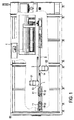
図1は、本発明に係る洗浄システム50の概略図であり、図2は、洗浄システム50の概略的上面図である。洗浄システム50は、上面(第1の面)11と下面(第2の面)12とを有する電極10のために、第1の輸送ベルト1と、第1の輸送ベルト1上に配置された第1の洗浄装置21と、第1の輸送ベルト1上に走行方向において第1の洗浄装置21の前方に配置された第1の放電装置13と、第2の輸送ベルト2と、第2の輸送ベルト上に配置された第2の洗浄装置22と、第2の輸送ベルト2上に走行方向において第2の洗浄装置22の前方に配置された第2の放電装置14と、電極10をさらに運ぶための第3の輸送ベルト3と、を有している。
FIG. 1 is a schematic view of a
電極10は、その下面12が第1の輸送ベルト1に接して、輸送ベルト1への方向で配置される。図1に示したように、第1の輸送ベルト1及び第2の輸送ベルト2は、有利には、第1の輸送ベルト1の吸引方向が第2の輸送ベルト2の吸引方向と反対になるように選択され、第1の輸送ベルト1及び第2の輸送ベルト2がその走行方向において部分的に重なるように配置されている。好ましくは重なりの程度は、少なくとも第1の輸送ベルト1又は第2の輸送ベルト2の走行方向における電極10の大きさに対応する。この第1の輸送ベルト1及び第2の輸送ベルト2の構成によって、電極10は、第1の輸送ベルト1から第2の輸送ベルト2へ、電極10がその上面11で第2の輸送ベルト2の方向に配置されるように移されるので、この移動の際、電極10を回転させる必要はない。第3の輸送ベルト3は、同様に第2の輸送ベルト2に接続されている。
The
図をわかりやすくするために、電極10は図1及び図2において縮尺に忠実には描かれておらず、一方の真空ベルト1、3と他方の輸送ベルト2との間の面には描かれていない。
For clarity of illustration, the
第1の輸送ベルト1上の第1の洗浄装置21と第2の輸送ベルト2上の第2の洗浄装置22とは、それぞれ少なくとも1つのブラシを有することが可能であり、当該ブラシは、好ましくは、円錐形ブラシ、渦巻き形ブラシ、ローラ状ブラシ、円形ブラシ、カップブラシ、べベルブラシを含む群から選択される。それに加えて、第1の洗浄装置21及び第2の洗浄装置22は、それぞれ少なくとも2つのブラシを有することが可能であり、当該ブラシは、互いに対して平行又は角度を成して配置されており、第1又は第2の輸送ベルトの走行方向に対して平行又は角度をなすように方向付けられている。
The
さらに、第1の洗浄装置21及び第2の洗浄装置22は、それぞれ1つのエアフローユニットを有しており、当該エアフローユニットは、電極10からブラシで取り払われた粒子をさらに運ぶエアフローを生成する。
Further, each of the
さらに、両方の洗浄装置21、22自体に、電極10の洗浄プロセス中におけるそれぞれのブラシの静電帯電を減少させるための放電ユニットを設けても良い。
Further, both the
さらに、洗浄システム50は、第3の輸送ベルト3上の洗浄された電極10の監視及び好ましくは目視検査のための監視ユニット4を有していても良い。
Furthermore, the
図2に示したように、電極10は、その側面が真空ベルト1、2の走行方向に対して斜めに延在するように、すなわち、真空ベルトの走行方向に対して、0°及び90°とは異なる角度に方向付けられるように、第1の輸送ベルト1上に、したがって第2の輸送ベルト2上にも配置される。好ましくは、この角度は約30°から45°の間の範囲である。このようにして、電極10の側面は、第1の洗浄装置21及び第2の洗浄装置22のブラシによって、より良く入念に洗浄され得る。
As shown in FIG. 2, the side surface of the
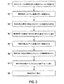
次に、図3のフローチャートに基づいて、上述の洗浄システム50を用いた電極10の洗浄方法のステップに再度言及する。
Next, the steps of the method for cleaning the
ステップS1では、まず電極10が第1の輸送ベルト1上に配置される。次にステップS2では、電極10は、第1の輸送ベルト1で第1の洗浄装置21へ移動させられる。第1の洗浄装置21の領域において、電極10は、第1の放電装置13を用いて静電放電される。
In step S <b> 1, first, the
ステップS3では、電極10は第1の輸送ベルト1上で第1の洗浄装置21を用いて洗浄される。このステップS3では、電極10は、第1の輸送ベルト1上で、少なくとも1つの回転するブラシで払われる。別の選択肢として、又は、追加的に、この電極上の粒子を、エアーナイフ又は超音波パルスによって剥離することができる。さらに、第1の洗浄装置21内の剥離された粒子は、エアフローによって運ばれる。
In step S <b> 3, the
ステップS4において、電極10は、第1の輸送ベルト1から第2の輸送ベルト2へと移される。両方の真空ベルト1、2が重なっていること、及び、反対の吸引作用を有するその相互の方向付けによって、電極10はその上面11で、第2の輸送ベルト2に向かって配置される。
In step S <b> 4, the
ステップS5において、電極10は、第2の輸送ベルト2を用いて、第2の洗浄装置22へと移動させられる。この第2の洗浄装置22の領域において、電極10は、第2の輸送ベルト2上で好ましくは第2の放電装置14を用いて静電放電される。
In step S <b> 5, the
ステップ6において、第2の輸送ベルト2上の電極10は、第2の洗浄装置22内で洗浄される。このステップS6では、第2の輸送ベルト2上の電極10を、少なくとも1つの回転するブラシで払うことができる。別の選択肢として、又は、追加的に、電極10上の粒子を、エアーナイフ又は超音波パルスによって剥離することもできる。さらに、第2の洗浄装置22内の剥離された粒子は、エアフローによって運ばれる。
In
引き続いてステップS7において、電極10は第2の輸送ベルト2から第3の輸送ベルト3に移される。この移動は、第1の輸送ベルト1と第2の輸送ベルト2との間の移動とは逆に行われる。最後にステップS8において、電極10は輸送ベルト3上でさらに運ばれ、洗浄された電極10の検査が行われ得る。
Subsequently, in step S <b> 7, the
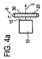
図4aから図4mは、本発明の様々な実施例に係る洗浄されるべき電極の走行方向及び配置に対する、ブラシ及びブラシの毛材を有する洗浄装置の配置の概略図であり、本発明はこれらの実施例の配置に制限されるものではない。 FIGS. 4a to 4m are schematic views of the arrangement of a cleaning device having brushes and bristle material relative to the travel direction and arrangement of electrodes to be cleaned according to various embodiments of the present invention. However, the present invention is not limited to the arrangement of the embodiment.
図4aに示した第1の実施例によると、ブラシ25は、洗浄されるべき電極10の輸送方向5に対して垂直かつ当該電極10の側面15に対して平行に配置され得る。ブラシ25は回転方向6に回転し、その回転軸は側面15に対しても、本図に示されていない輸送ベルトに対しても平行であり、ブラシの毛材30は、ブラシ25の被覆面に配置されている。第1の実施例の配置によって、側面15と、電極10の上面でもある当該側面と向かい合う側面とは、特に良好に洗浄され得る。
According to the first embodiment shown in FIG. 4 a, the
図4bに示した第2の実施例によると、ブラシ25は、洗浄されるべき電極10の輸送方向5に対して垂直に配置され得る。この電極10の第1の側面15aと第2の側面15bとは、ブラシ25に対して約45°の角度で配置可能であり、ブラシ25は回転方向6に回転し、その回転軸は第1第2の側面15a及び第2の側面15bに対して約45°の角度で配置されると共に、本図に示されていない輸送ベルトに対して平行でもある。ブラシの毛材30は、ブラシ25の被覆面に配置されている。第2の実施例の配置によって、電極10の4つの側面15a、15b、15c、15d全てと上面とが特に良好に洗浄され得る。
According to the second embodiment shown in FIG. 4b, the
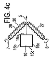
図4cに示した第3の実施例によると、第1のブラシ26と第2のブラシ27とは、洗浄されるべき電極10の輸送方向5に対してそれぞれ約45°の角度で配置され得る。電極10の第1の側面15aは輸送方向5に対して垂直に、電極10の第2の側面15b及び第3の側面15cはそれぞれ輸送方向5に対して平行に配置され得る。第1のブラシ26は回転方向7において、第2のブラシ27は好ましくは反対の回転方向8において回転し、その回転軸は輸送方向5に対してそれぞれ約45°の角度で配置されると共に、本図に示されていない輸送ベルトに対して平行でもある。ブラシの毛材30は、第1のブラシ26及び第2のブラシ27の被覆面上にそれぞれ配置されている。第3の実施例の配置によっても、電極10の4つの側面15a、15b、15c、15d全てと上面とが特に良好に洗浄され得る。
According to the third embodiment shown in FIG. 4c, the
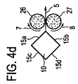
図4dに示した第4の実施例によると、第1のブラシ26と第2のブラシ27とは、洗浄されるべき電極10の輸送方向5に対してそれぞれ垂直に、かつ、本図に示されていない輸送ベルトに対して垂直に配置され得る。電極10の第1の側面15a及び第2の側面15bは、それぞれ輸送方向5に対して約45°の角度で配置され得る。第1のブラシ26は回転方向7において、第2のブラシ27は好ましくは反対の回転方向8において回転し、その回転軸は本図に示されていない輸送ベルトに対してそれぞれ垂直である。ブラシの毛材30は、第1のブラシ26及び第2のブラシ27の底面にそれぞれ配置されている。このようにして、電極10の上面が特に良好に洗浄され得る。
According to the fourth embodiment shown in FIG. 4d, the
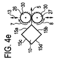
図4eに示した第5の実施例によると、第1のブラシ26と第2のブラシ27とは、それぞれ洗浄されるべき電極10の輸送方向5に対して垂直に、かつ、本図に示されていない輸送ベルトに対して垂直に配置され得る。電極10の第1の側面15a及び第2の側面15bは、それぞれ輸送方向5に対して約45°の角度で配置され得る。第1のブラシ26は回転方向7において、第2のブラシ27は好ましくは反対の回転方向8において回転し、その回転軸は本図に示されていない輸送ベルトに対してそれぞれ垂直である。ブラシの毛材30は、第1のブラシ26及び第2のブラシ27の被覆面にそれぞれ配置されており、第1のブラシ26及び第2のブラシ27は、輸送方向5に対して略垂直に配置された相対運動方向13において、互いに可動であるように配置されている。この相対運動13によって、4つの側面15a、15b、15c、15d全てが特に良好に洗浄され得る。
According to the fifth embodiment shown in FIG. 4e, the
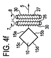
図4fに示した第6の実施例によると、第1のブラシ26と第2のブラシ27とは、洗浄されるべき電極10の輸送方向5に対して垂直に配置され得る。この電極10の第1の側面15aと第2の側面15bとは、第1のブラシ26及び第2のブラシ27に対して約45°の角度で配置可能であり、第1のブラシ26は回転方向7において、第2のブラシ28は好ましくは反対の回転方向8において回転し、その回転軸は第1及び第2の側面15a、15bに対して約45°の角度で配置されると共に、本図に示されていない輸送ベルトに対して平行でもある。ブラシの毛材30は、第1のブラシ26の被覆面にも、第2のブラシ27の被覆面にも配置されている。第1のブラシ26及び第2のブラシ27の反対の回転方向7、8によって、電極10の洗浄が改善され得る。
According to the sixth embodiment shown in FIG. 4f, the
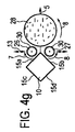
図4gに示した第7の実施例によると、第1のブラシ26及び第2のブラシ27、さらに第3のブラシ28も、それぞれ洗浄されるべき電極10の輸送方向5に対して垂直に、かつ、本図に示されていない輸送ベルトに対して垂直に配置され得る。この電極10の第1の側面15aと第2の側面15bとは、輸送方向5に対して約45°の角度で配置されており、第1のブラシ26は回転方向7において、第2のブラシ27は好ましくは反対の回転方向8において回転し、その回転軸は本図に示されていない輸送ベルトに対してそれぞれ垂直であり、ブラシの毛材30は、第1のブラシ26及び第2のブラシ27の被覆面にそれぞれ配置されており、第1のブラシ26及び第2のブラシ27は、輸送方向5に対して略垂直に配置された相対運動方向13において、互いに可動であるように配置されており、第3のブラシ28の毛材は、その底面に配置されている。第7の実施例に係る配置は、第4及び第5の実施例に係る配置の利点を組み合わせたものであり、電極10の4つの側面15a、15b、15c、15dも上面も、特に良好に洗浄され得る。
According to the seventh embodiment shown in FIG. 4g, the
図4hに示した第8の実施例によると、第1のブラシ26と第2のブラシ27とは、洗浄されるべき電極10の輸送方向5に対して垂直に、かつ、電極10の側面15に対して平行に配置され得る。第1のブラシ26は回転方向7において、第2のブラシ27は好ましくは反対の回転方向8において回転し、その回転軸は側面15に対しても、本図に示されていない輸送ベルトに対しても平行であり、ブラシの毛材30は、第1のブラシ26及び第2のブラシ27の被覆面にそれぞれ配置されている。第6の実施例と同様に、第8の実施例では、第1のブラシ26及び第2のブラシ27の反対の回転方向7、8によって、電極10の洗浄が改善され得る。
According to the eighth embodiment shown in FIG. 4h, the
図4iに示した第9の実施例によると、第1のブラシ26と第2のブラシ27とは、洗浄されるべき電極10の輸送方向5に対して平行に、かつ、電極10の側面15に対して垂直に配置され得る。第3のブラシ28と第4のブラシ29とは、輸送方向5に対して垂直かつ電極10の側面15に対して平行に配置され得る。第1のブラシ26は回転方向7において、第2のブラシ27は好ましくは反対の回転方向8において回転し、その回転軸は側面15に対して垂直かつ本図に示されていない輸送ベルトに対して平行であり、ブラシの毛材30は、第1のブラシ26及び第2のブラシ27の被覆面にそれぞれ配置されている。第3のブラシ28は回転方向9において、第4のブラシ29は好ましくは回転方向9とは反対の回転方向14において回転し、その回転軸は側面15に対しても、本図に示されていない輸送ベルトに対しても平行であり、ブラシの毛材30は、第3のブラシ28及び第4のブラシ29の被覆面にそれぞれ配置されている。第9の実施例の配置によって、電極10の4つの側面15a、15b、15c、15dも上面も、特に良好に洗浄され得る。
According to the ninth embodiment shown in FIG. 4 i, the
図4jに示した第10の実施例によると、第1のブラシ26と第2のブラシ27とは、洗浄されるべき電極10の輸送方向5に対して平行に、かつ、電極10の側面15に対して垂直に配置され得る。第1のブラシ26は回転方向7において、第2のブラシ27は好ましくは反対の回転方向8において回転し、その回転軸は側面15に対して垂直かつ本図に示されていない輸送ベルトに対して平行であり、ブラシの毛材30は、第1のブラシ26及び第2のブラシ27の被覆面にそれぞれ配置されている。これに加えて、第10の実施例においては、ブラシの毛材は好ましくはらせん状に、第1及び第2のブラシ上に配置されており、それによって、側面15b、15cの洗浄に加えて、洗浄されるべき電極10の輸送も支援される。
According to the tenth embodiment shown in FIG. 4 j, the
図4kには第11の実施例が示されている。当該実施例においては、ブラシ25は、回転方向6を有し、輸送方向5に対して垂直かつ電極10の上面11及び側面15に対して鋭角、好ましくは約45°の角度で配置されており、ブラシの毛材30は、ブラシ25の被覆面に配置されている。この第11の実施例の配置は、電極10の側面15及び上面の洗浄を改善することができる。
FIG. 4k shows an eleventh embodiment. In this embodiment, the
図4lには第12の実施例が示されている。当該実施例においては、ブラシ25は、回転方向6を有し、輸送方向5に対して垂直かつ電極10の側面15に対して平行に配置されており、ブラシの毛材30はブラシ25の被覆面に配置されており、ブラシ25は円錐形を有している。
FIG. 4l shows a twelfth embodiment. In this embodiment, the
図4mには第13の実施例が示されている。当該実施例においては、ブラシ25は、回転方向6を有し、輸送方向5に対して垂直かつ電極10の上面11及び側面15に対して鋭角、好ましくは約45°の角度で配置されており、ブラシの毛材30は、好ましくはブラシ25の底面の外周の円環に「カップ様に」配置されている。
FIG. 4m shows a thirteenth embodiment. In this embodiment, the
1 第1の輸送ベルト
2 第2の輸送ベルト
3 第3の輸送ベルト
4 監視ユニット
5 物体の輸送方向
6 ブラシの回転方向
7 第1のブラシの回転方向
8 第2のブラシの回転方向
9 第3のブラシの回転方向
10 物体
11 物体の第1の面
12 物体の第2の面
13 第1及び第2のブラシの相対運動方向
14 第4のブラシの回転方向
15 洗浄されるべき側面
15a 洗浄されるべき第1の側面
15b 洗浄されるべき第2の側面
15c 洗浄されるべき第3の側面
15d 洗浄されるべき第4の側面
21 第1の洗浄装置
22 第2の洗浄装置
25 ブラシ
26 第1のブラシ
27 第2のブラシ
28 第3のブラシ
29 第4のブラシ
30 ブラシの毛材
50 洗浄システム
DESCRIPTION OF SYMBOLS 1
Claims (22)
前記洗浄方法が、
少なくとも1つの物体(10)を第1の輸送ベルト(1)上に、前記第2の面(12)が前記第1の輸送ベルト(1)に対向するように配置するステップ(S1)と、
前記物体(10)を、前記第1の輸送ベルト(1)で、第1の洗浄装置(21)に移動させるステップ(S2)と、
前記第1の洗浄装置(21)によって、前記物体(10)の前記第1の面(11)及び好ましくは少なくとも1つの側面を、前記第1の輸送ベルト(1)上で洗浄するステップ(S3)と、
前記物体(10)を、前記第1の輸送ベルト(1)から第2の輸送ベルト(2)へ、前記第1の面(11)が前記第2の輸送ベルト(2)に対向するように移すステップ(S4)と、
前記第2の輸送ベルト(2)によって、前記物体(10)を第2の洗浄装置(22)へと移動させるステップ(S5)と、
前記第2の洗浄装置(22)によって、前記物体(10)の前記第2の面(11)及び好ましくは少なくとも1つの側面を、前記第2の輸送ベルト(2)上で洗浄するステップ(S6)と、
を有していることを特徴とする方法。 A method for cleaning a sheet-like or plate-like object (10), in particular an electrode and / or separator constituting an electrochemical energy storage device, or a part of these electrodes or separator, The sheet-like or plate-like object (10) includes a first surface (11), a second surface (12) facing the first surface, and the first surface (11) and the second surface (12). And at least one side connecting
The cleaning method comprises:
Placing (S1) at least one object (10) on the first transport belt (1) such that the second surface (12) faces the first transport belt (1);
Moving the object (10) to the first cleaning device (21) with the first transport belt (1) (S2);
The step (S3) of cleaning the first surface (11) and preferably at least one side surface of the object (10) on the first transport belt (1) by the first cleaning device (21). )When,
The object (10) is moved from the first transport belt (1) to the second transport belt (2) so that the first surface (11) faces the second transport belt (2). Transferring (S4);
Moving the object (10) to the second cleaning device (22) by the second transport belt (2) (S5);
Step (S6) for cleaning the second surface (11) and preferably at least one side surface of the object (10) on the second transport belt (2) by the second cleaning device (22). )When,
A method characterized by comprising:
前記装置(50)は、
前記物体(10)を第1の洗浄装置(21)に移動させるための第1の輸送ベルト(1)であって、前記物体の第2の面(11)が前記第1の輸送ベルト(1)に対向するように前記物体(10)を受容すべく配置かつ構成された前記第1の輸送ベルト(1)と、
前記物体(10)の第1の面(12)及び少なくとも1つの側面を前記第1の輸送ベルト(1)上で洗浄できるように配置かつ構成された第1の洗浄装置(21)と、
前記物体(10)を前記第1の輸送ベルト(1)から受け取り、第2の洗浄装置(22)へ移動させる第2の輸送ベルト(2)であって、前記物体の第1の面(12)が前記第2の輸送ベルト(1)に対向するように前記物体(10)を受容すべく配置かつ構成された前記第2の輸送ベルト(1)と、
前記物体(10)の第2の面(11)及び少なくとも1つの側面を前記第2の輸送ベルト(2)上で洗浄できるように配置かつ構成された第2の洗浄装置(22)と、
を有していることを特徴とする装置(50)。 An apparatus (50) for cleaning sheets or plates (10), in particular electrodes and / or separators constituting the electrochemical energy storage device, or parts of these electrodes or separators. Then, the sheet-like or plate-like object (10) includes the first surface (11), the second surface (12) facing the first surface, the first surface (11), and the second surface. In the device (50) having at least one side connecting the surface (12),
The device (50)
A first transport belt (1) for moving the object (10) to a first cleaning device (21), wherein the second surface (11) of the object is the first transport belt (1). The first transport belt (1) arranged and configured to receive the object (10) to face the
A first cleaning device (21) arranged and configured to be able to clean the first surface (12) and at least one side surface of the object (10) on the first transport belt (1);
A second transport belt (2) for receiving said object (10) from said first transport belt (1) and moving it to a second cleaning device (22), said first surface (12) of said object The second transport belt (1) arranged and configured to receive the object (10) such that the second transport belt (1) faces the second transport belt (1);
A second cleaning device (22) arranged and configured to clean the second surface (11) and at least one side surface of the object (10) on the second transport belt (2);
A device (50) characterized by comprising:
Applications Claiming Priority (3)
| Application Number | Priority Date | Filing Date | Title |
|---|---|---|---|
| DE102010051668.6 | 2010-11-17 | ||
| DE102010051668A DE102010051668A1 (en) | 2010-11-17 | 2010-11-17 | Method and system for cleaning sheet or plate-shaped objects |
| PCT/EP2011/005610 WO2012065695A2 (en) | 2010-11-17 | 2011-11-08 | Method and system for cleaning sheet- or plate-like objects |
Publications (2)
| Publication Number | Publication Date |
|---|---|
| JP2014502407A true JP2014502407A (en) | 2014-01-30 |
| JP2014502407A5 JP2014502407A5 (en) | 2014-07-31 |
Family
ID=44983483
Family Applications (1)
| Application Number | Title | Priority Date | Filing Date |
|---|---|---|---|
| JP2013539156A Pending JP2014502407A (en) | 2010-11-17 | 2011-11-08 | Cleaning method and cleaning system for sheet-like or plate-like object |
Country Status (6)
| Country | Link |
|---|---|
| EP (1) | EP2641286B1 (en) |
| JP (1) | JP2014502407A (en) |
| KR (1) | KR20130131368A (en) |
| CN (1) | CN103222086A (en) |
| DE (1) | DE102010051668A1 (en) |
| WO (1) | WO2012065695A2 (en) |
Cited By (1)
| Publication number | Priority date | Publication date | Assignee | Title |
|---|---|---|---|---|
| CN112157071A (en) * | 2020-09-21 | 2021-01-01 | 邵东县华帝龙箱包有限公司 | Cloth bits clearing device is used in case and bag production |
Families Citing this family (10)
| Publication number | Priority date | Publication date | Assignee | Title |
|---|---|---|---|---|
| US10343193B2 (en) | 2014-02-24 | 2019-07-09 | The Boeing Company | System and method for surface cleaning |
| US10399128B2 (en) | 2014-06-05 | 2019-09-03 | Illinois Tool Works Inc. | System and method for cleaning an object |
| KR102001605B1 (en) * | 2015-11-30 | 2019-07-18 | 주식회사 엘지화학 | Washing apparatus for membrane |
| CN105834168A (en) * | 2016-05-12 | 2016-08-10 | 深圳市深鸿海自动化设备有限公司 | Dust removing and static electricity removing cleaning machine used before LCM attachment |
| CN106076922B (en) * | 2016-06-13 | 2018-11-27 | 广东溢达纺织有限公司 | Heald auto-cleaning method |
| CN107597641A (en) * | 2017-10-17 | 2018-01-19 | 东莞市中锂自动化设备有限公司 | A kind of automatic brush dust sheet selection machine |
| DE102018214167A1 (en) * | 2018-08-22 | 2020-02-27 | Meiko Maschinenbau Gmbh & Co. Kg | Cleaning system and method for cleaning items to be cleaned |
| CN113793916B (en) * | 2021-08-13 | 2023-05-02 | 永州时代新能源科技有限公司 | Continuous rolling device for lithium ion battery electrode |
| EP4152469A1 (en) | 2021-09-17 | 2023-03-22 | Technische Universität Berlin | Method and device for creating an electrode-separator unit for a battery cell |
| CN115709188A (en) * | 2022-11-03 | 2023-02-24 | 扬州富铭新材料有限公司 | Automatic plate shifting system for processing and producing plastic wall bricks |
Citations (3)
| Publication number | Priority date | Publication date | Assignee | Title |
|---|---|---|---|---|
| JPS6340253A (en) * | 1986-08-04 | 1988-02-20 | Sanyo Electric Co Ltd | Manufacture of electrode for battery |
| JPH09286551A (en) * | 1996-04-22 | 1997-11-04 | Shin Kobe Electric Mach Co Ltd | Method and device for attraction conveying and accumulating pole plate |
| JP2005267870A (en) * | 2004-03-16 | 2005-09-29 | Tdk Corp | Method and apparatus for manufacturing secondary battery or electric double-layer capacitor |
Family Cites Families (12)
| Publication number | Priority date | Publication date | Assignee | Title |
|---|---|---|---|---|
| NL256901A (en) * | 1957-08-22 | |||
| CH437678A (en) * | 1966-08-05 | 1967-06-15 | Ed Hildebrand Fa Ing | Dish washing machine |
| DE3506556A1 (en) * | 1985-02-25 | 1986-09-04 | Oscar von 3008 Garbsen Wedekind | Process and device for cleaning flat small parts, in particular coins |
| DE3921288C1 (en) * | 1989-06-29 | 1990-08-23 | Accumulatorenwerke Hoppecke Carl Zoellner & Sohn Gmbh & Co Kg, 5790 Brilon, De | |
| JP2680783B2 (en) * | 1994-07-14 | 1997-11-19 | 昭和金属工業株式会社 | Coin cleaning equipment |
| ATE372566T1 (en) * | 1996-03-07 | 2007-09-15 | Coinstar Inc | METHOD AND DEVICE FOR TREATING CASH COINS |
| EP1046370A1 (en) * | 1999-04-19 | 2000-10-25 | CHEMISCHE FABRIK DR. WEIGERT (GMBH & CO.) | Conveyor dishwasher |
| DE10354168A1 (en) * | 2003-11-19 | 2005-06-23 | Eltex-Elektrostatik Gmbh | A method for discharging the electrostatic field from material conveyor belts has an electrode across the belt having a high frequency electrical charge with another earthed on the other side |
| DE102004016961A1 (en) * | 2004-04-06 | 2005-10-27 | Giesecke & Devrient Gmbh | System for processing bank notes comprises a sorting device in a sealed housing, and a cleaning device arranged outside the sorting device housing |
| DE202006009823U1 (en) * | 2005-12-21 | 2006-11-16 | Eltex-Elektrostatik Gmbh | Device for contactless removal of electrostatic electrical double layer from flat electrically insulating material has contactless compensating device for feed of charge particles to flat material for compensation of charges |
| JP4485598B1 (en) * | 2009-09-10 | 2010-06-23 | 善博 平川 | Method for cleaning articles using ultrasonic waves |
| CN201618705U (en) * | 2010-01-28 | 2010-11-03 | 杭州万马高能量电池有限公司 | Cleaning machine for battery pole piece |
-
2010
- 2010-11-17 DE DE102010051668A patent/DE102010051668A1/en not_active Withdrawn
-
2011
- 2011-11-08 WO PCT/EP2011/005610 patent/WO2012065695A2/en active Application Filing
- 2011-11-08 CN CN2011800551668A patent/CN103222086A/en active Pending
- 2011-11-08 JP JP2013539156A patent/JP2014502407A/en active Pending
- 2011-11-08 EP EP11782552.1A patent/EP2641286B1/en not_active Not-in-force
- 2011-11-08 KR KR1020137015079A patent/KR20130131368A/en not_active Application Discontinuation
Patent Citations (3)
| Publication number | Priority date | Publication date | Assignee | Title |
|---|---|---|---|---|
| JPS6340253A (en) * | 1986-08-04 | 1988-02-20 | Sanyo Electric Co Ltd | Manufacture of electrode for battery |
| JPH09286551A (en) * | 1996-04-22 | 1997-11-04 | Shin Kobe Electric Mach Co Ltd | Method and device for attraction conveying and accumulating pole plate |
| JP2005267870A (en) * | 2004-03-16 | 2005-09-29 | Tdk Corp | Method and apparatus for manufacturing secondary battery or electric double-layer capacitor |
Cited By (1)
| Publication number | Priority date | Publication date | Assignee | Title |
|---|---|---|---|---|
| CN112157071A (en) * | 2020-09-21 | 2021-01-01 | 邵东县华帝龙箱包有限公司 | Cloth bits clearing device is used in case and bag production |
Also Published As
| Publication number | Publication date |
|---|---|
| WO2012065695A3 (en) | 2012-08-16 |
| DE102010051668A1 (en) | 2012-05-24 |
| CN103222086A (en) | 2013-07-24 |
| EP2641286B1 (en) | 2015-01-07 |
| WO2012065695A2 (en) | 2012-05-24 |
| KR20130131368A (en) | 2013-12-03 |
| EP2641286A2 (en) | 2013-09-25 |
Similar Documents
| Publication | Publication Date | Title |
|---|---|---|
| JP2014502407A (en) | Cleaning method and cleaning system for sheet-like or plate-like object | |
| JP6868299B2 (en) | Lithium battery using nanoporous separator layer | |
| TWI536649B (en) | Lithium ion battery | |
| JP6208708B2 (en) | Lithium ion secondary battery and system using the same | |
| CN105706275B (en) | Battery | |
| EP3416225B1 (en) | Electrode assembly and manufacturing method therefor | |
| KR20140060366A (en) | Graphene current collectors in batteries for portable electronic devices | |
| TW201711264A (en) | Longitudinal constraints for energy storage devices | |
| JP2011165672A (en) | Electrode assembly with interelectrode resistance difference of tab-lead connection part minimized and electrochemical cell equipped with the same | |
| KR101578179B1 (en) | Device for removing coating materials when cutting jelly rolly in the jelly roll winding system of electric double layer capacitors | |
| US11876185B2 (en) | Method for manufacturing secondary battery and secondary battery | |
| JP6808925B2 (en) | Power storage element and manufacturing method of power storage element | |
| JP2016066520A (en) | Electricity storage device | |
| US10424808B2 (en) | Electrode roll and manufacturing method for electrode roll | |
| CN106463698B (en) | Secondary battery and method for manufacturing the same | |
| JP6454504B2 (en) | Electric storage device and stacked electric storage device | |
| US20140102478A1 (en) | Method and system for cleaning sheet- or plate-shaped objects | |
| KR20160142816A (en) | Method and apparatus for applying a self-adhesive film to an electrical energy storage cell | |
| KR101600536B1 (en) | Device for brushing cutter of separation pla plate in the jelly roll winding system of a electric conduction plate for electric double layer capacitors | |
| US20190181493A1 (en) | Separator/Current Collector Unit for Galvanic Cells | |
| KR101590671B1 (en) | Ultrasonic welding assembly and Fabricating method of secondary battery using the same | |
| KR20140032971A (en) | Method and system for producing leaf-like or plate-like objects | |
| JP6500857B2 (en) | Method of manufacturing electrode body | |
| TWI500199B (en) | Secondary battery comprising multiple electrode assembly | |
| CN207967197U (en) | The polymer Li-ion battery of monomer vast capacity |
Legal Events
| Date | Code | Title | Description |
|---|---|---|---|
| A521 | Request for written amendment filed |
Free format text: JAPANESE INTERMEDIATE CODE: A523 Effective date: 20140611 |
|
| A621 | Written request for application examination |
Free format text: JAPANESE INTERMEDIATE CODE: A621 Effective date: 20140611 |
|
| A131 | Notification of reasons for refusal |
Free format text: JAPANESE INTERMEDIATE CODE: A131 Effective date: 20141028 |
|
| A977 | Report on retrieval |
Free format text: JAPANESE INTERMEDIATE CODE: A971007 Effective date: 20141029 |
|
| RD04 | Notification of resignation of power of attorney |
Free format text: JAPANESE INTERMEDIATE CODE: A7424 Effective date: 20141217 |
|
| A02 | Decision of refusal |
Free format text: JAPANESE INTERMEDIATE CODE: A02 Effective date: 20150330 |