JP2014180193A - Synchronous motor with high responsiveness - Google Patents
Synchronous motor with high responsiveness Download PDFInfo
- Publication number
- JP2014180193A JP2014180193A JP2014023774A JP2014023774A JP2014180193A JP 2014180193 A JP2014180193 A JP 2014180193A JP 2014023774 A JP2014023774 A JP 2014023774A JP 2014023774 A JP2014023774 A JP 2014023774A JP 2014180193 A JP2014180193 A JP 2014180193A
- Authority
- JP
- Japan
- Prior art keywords
- rotor
- synchronous motor
- magnet group
- axial direction
- pole
- Prior art date
- Legal status (The legal status is an assumption and is not a legal conclusion. Google has not performed a legal analysis and makes no representation as to the accuracy of the status listed.)
- Pending
Links
Images


Classifications
-
- H—ELECTRICITY
- H02—GENERATION; CONVERSION OR DISTRIBUTION OF ELECTRIC POWER
- H02K—DYNAMO-ELECTRIC MACHINES
- H02K1/00—Details of the magnetic circuit
- H02K1/06—Details of the magnetic circuit characterised by the shape, form or construction
- H02K1/22—Rotating parts of the magnetic circuit
- H02K1/27—Rotor cores with permanent magnets
- H02K1/2706—Inner rotors
- H02K1/272—Inner rotors the magnetisation axis of the magnets being perpendicular to the rotor axis
- H02K1/274—Inner rotors the magnetisation axis of the magnets being perpendicular to the rotor axis the rotor consisting of two or more circumferentially positioned magnets
- H02K1/2753—Inner rotors the magnetisation axis of the magnets being perpendicular to the rotor axis the rotor consisting of two or more circumferentially positioned magnets the rotor consisting of magnets or groups of magnets arranged with alternating polarity
- H02K1/276—Magnets embedded in the magnetic core, e.g. interior permanent magnets [IPM]
- H02K1/2766—Magnets embedded in the magnetic core, e.g. interior permanent magnets [IPM] having a flux concentration effect
- H02K1/2773—Magnets embedded in the magnetic core, e.g. interior permanent magnets [IPM] having a flux concentration effect consisting of tangentially magnetized radial magnets
-
- H—ELECTRICITY
- H02—GENERATION; CONVERSION OR DISTRIBUTION OF ELECTRIC POWER
- H02K—DYNAMO-ELECTRIC MACHINES
- H02K21/00—Synchronous motors having permanent magnets; Synchronous generators having permanent magnets
- H02K21/12—Synchronous motors having permanent magnets; Synchronous generators having permanent magnets with stationary armatures and rotating magnets
- H02K21/14—Synchronous motors having permanent magnets; Synchronous generators having permanent magnets with stationary armatures and rotating magnets with magnets rotating within the armatures
- H02K21/16—Synchronous motors having permanent magnets; Synchronous generators having permanent magnets with stationary armatures and rotating magnets with magnets rotating within the armatures having annular armature cores with salient poles
-
- H—ELECTRICITY
- H02—GENERATION; CONVERSION OR DISTRIBUTION OF ELECTRIC POWER
- H02K—DYNAMO-ELECTRIC MACHINES
- H02K29/00—Motors or generators having non-mechanical commutating devices, e.g. discharge tubes or semiconductor devices
- H02K29/03—Motors or generators having non-mechanical commutating devices, e.g. discharge tubes or semiconductor devices with a magnetic circuit specially adapted for avoiding torque ripples or self-starting problems
-
- H—ELECTRICITY
- H02—GENERATION; CONVERSION OR DISTRIBUTION OF ELECTRIC POWER
- H02K—DYNAMO-ELECTRIC MACHINES
- H02K2201/00—Specific aspects not provided for in the other groups of this subclass relating to the magnetic circuits
- H02K2201/06—Magnetic cores, or permanent magnets characterised by their skew
-
- H—ELECTRICITY
- H02—GENERATION; CONVERSION OR DISTRIBUTION OF ELECTRIC POWER
- H02K—DYNAMO-ELECTRIC MACHINES
- H02K2213/00—Specific aspects, not otherwise provided for and not covered by codes H02K2201/00 - H02K2211/00
- H02K2213/03—Machines characterised by numerical values, ranges, mathematical expressions or similar information
Abstract
Description
本発明は、同期電動機、特に高い応答性を有する同期電動機に関する。 The present invention relates to a synchronous motor, and more particularly to a synchronous motor having high responsiveness.
従来のモータにおいては、予め巻かれたコイルをステータのスロットに挿入する分布巻方式が採用されていた。これに対し、近年では、コイルを絶縁物を介してステータティースに直接的に巻付ける集中巻方式が採用されている。 In a conventional motor, a distributed winding method in which a coil wound in advance is inserted into a slot of a stator has been adopted. On the other hand, in recent years, a concentrated winding method in which a coil is directly wound around stator teeth via an insulator has been adopted.
集中巻きステータにおいては、コイルを直接的に巻付けているので、ステータコア端面におけるコイルを少なくし、その結果、コイルの周長を大幅に短くできる。このため、太い電線を高密度で巻付けることにより、電気抵抗は小さくなる。さらに、コイルエンドの寸法を小さくできるので、モータをコンパクトにしつつ大トルクを得ることができる。 In the concentrated winding stator, since the coil is wound directly, the number of coils on the end face of the stator core is reduced, and as a result, the circumferential length of the coil can be greatly shortened. For this reason, an electrical resistance becomes small by winding a thick electric wire with high density. Furthermore, since the size of the coil end can be reduced, a large torque can be obtained while making the motor compact.
特許文献1には、磁極とステータ内周面との間のギャップ長をロータの一極分の部分の中心付近において小さくすると共に、ロータの一極分の部分の両端付近で大きくすることが開示されている。これにより、コギングトルクを低減させられる。
ところで、高頻度、高速でのピックアンドプレイス動作が要求される高速高応答のロボットに使用されるモータは、イナーシャを極力小さく抑えると共に、連続して長時間使用できる連続定格トルクが大きいことが要求される。つまり、ロボットに使用されるモータは、トルク対イナーシャの比が極めて大きいことが要求される。 By the way, motors used in high-speed, high-response robots that require high-frequency, high-speed pick-and-place operations require that inertia be kept as small as possible and that the continuous rated torque that can be used continuously for a long time be large. Is done. That is, the motor used for the robot is required to have a very large torque to inertia ratio.
この目的のために、モータのロータ径を極力小さくすると共に、モータのステータを集中巻構造にしてスロット数を少なくするのが有利である。しかしながら、そのような場合には、コギングトルクを抑えることが難しい。このため、集中巻きステータを備えたモータは車載用モータ、家電用モータなどの用途に限定され、円滑な回転が要求されるロボットのサーボモータにはほとんど適用されない。 For this purpose, it is advantageous to reduce the rotor diameter of the motor as much as possible and reduce the number of slots by making the motor stator a concentrated winding structure. However, in such a case, it is difficult to suppress the cogging torque. For this reason, the motor provided with the concentrated winding stator is limited to uses such as a vehicle-mounted motor and a motor for home appliances, and is hardly applied to a servo motor for a robot that requires smooth rotation.
また、磁石が半径方向に配置されたロータはギャップ磁束密度を高められるので、大トルクを実現することができ、このような構造の十極のロータと十二スロットの集中巻きステータとを組合わせたモータが存在している。しかしながら、十極のロータと十二スロットの集中巻きステータとを組合わせたモータにおいては、高速で負荷電流が流れたときにロータに発生する渦電流損が大きくなる。このため、そのようなモータを高速で頻繁に使用されるロボットの分野で使用するのは難しい。 In addition, a rotor with magnets arranged in the radial direction can increase the gap magnetic flux density, so that a large torque can be realized, and a 10-pole rotor having such a structure and a 12-slot concentrated winding stator are combined. A motor is present. However, in a motor in which a ten-pole rotor and a twelve-slot concentrated winding stator are combined, eddy current loss generated in the rotor increases when a load current flows at high speed. For this reason, it is difficult to use such a motor in the field of robots that are frequently used at high speed.
本発明はこのような事情に鑑みてなされたものであり、低イナーシャ、大トルクで且つ回転が滑らかで、高速領域でも損失を抑えることのできる同期電動機を提供することを目的とする。 The present invention has been made in view of such circumstances, and an object thereof is to provide a synchronous motor that has low inertia, large torque, smooth rotation, and can suppress loss even in a high speed region.
前述した目的を達成するために1番目の発明によれば、十二個のスロットが形成された集中巻ステータと、該集中巻きステータの内側に配置されていて八つの磁石が半径方向に配置された八極のロータと、を具備し、前記ロータの一極分の外形形状の一部分または全体を、三角関数の曲線およびこれに近似した曲線で構成した同期電動機が提供される。
2番目の発明によれば、1番目の発明において、前記ロータの一極分の外形形状の前記一部分が前記ロータの一極分の外形形状の中心部分であるようにした。
3番目の発明によれば、1番目または2番目の発明において、前記ロータは、半径方向に配置された八つの磁石からなる第一磁石群と、前記同期電動機の軸線方向において前記第一磁石群に隣接して配置されていて半径方向に配置された八つの磁石からなる第二磁石群とを含んでおり、前記第一磁石群と前記第二磁石群とが前記同期電動機の軸線方向周りに互いに7.5°だけズレているようにした。
4番目の発明によれば、1番目または2番目の発明において、前記ロータは、半径方向に配置された八つの磁石からなる第一磁石群と、前記同期電動機の軸線方向において前記第一磁石群に隣接して配置されていて半径方向に配置された八つの磁石からなる第二磁石群と、前記同期電動機の軸線方向において前記第二磁石群に隣接して配置されていて半径方向に配置された八つの磁石からなる第三磁石群とを含んでおり、前記同期電動機の軸線方向において前記第三磁石群に隣接して配置されていて半径方向に配置された八つの磁石からなる第四磁石群とを含んでおり、前記第一磁石群から前記第四磁石群のうち互いに隣接する二つの磁石群は前記同期電動機の軸線方向周りに互いに3.75°だけズレているようにした。
5番目の発明によれば、3番目の発明において、前記ロータにおける前記第一磁石群の第一ロータヨークには、前記ロータの各極に対応する部分の中心線から前記同期電動機の軸線方向周りに3.75°だけズレた位置に第一締結穴が形成されており、前記ロータにおける前記第二磁石群の第二ロータヨークには、前記ロータの各極に対応する部分の中心線から前記同期電動機の軸線方向周りで且つ前記第一締結穴とは反対方向に3.75°だけズレた位置に第二締結穴が形成されている。
6番目の発明によれば、4番目の発明において、前記ロータにおける前記第一磁石群の第一ロータヨークには、前記ロータの各極に対応する部分の中心線から前記同期電動機の軸線方向周りに5.625°だけズレた位置に第一締結穴が形成されており、前記ロータにおける前記第二磁石群の第二ロータヨークには、前記ロータの各極に対応する部分の中心線から前記同期電動機の軸線方向周りで且つ前記第一締結穴と同一方向に1.875°だけズレた位置に第二締結穴が形成されており、前記ロータにおける前記第三磁石群の第三ロータヨークには、前記ロータの各極に対応する部分の中心線から前記同期電動機の軸線方向周りで且つ前記第一締結穴と反対方向に1.875°だけズレた位置に第三締結穴がそれぞれ形成されており、前記ロータにおける前記第四磁石群の第四ロータヨークには、前記ロータの各極に対応する部分の中心線から前記同期電動機の軸線方向周りで且つ前記第一締結穴と反対方向に5.625°だけズレた位置に第四締結穴がそれぞれ形成されている。
In order to achieve the above-described object, according to the first invention, a concentrated winding stator having twelve slots, and eight magnets arranged radially inside the concentrated winding stator are arranged. A synchronous motor in which a part or the whole of the outer shape of one pole of the rotor is constituted by a curve of a trigonometric function and a curve similar thereto.
According to the second invention, in the first invention, the part of the outer shape of one pole of the rotor is a central portion of the outer shape of one pole of the rotor.
According to a third invention, in the first or second invention, the rotor comprises a first magnet group comprising eight magnets arranged in a radial direction, and the first magnet group in the axial direction of the synchronous motor. And a second magnet group consisting of eight magnets arranged in the radial direction, and the first magnet group and the second magnet group are arranged around the axial direction of the synchronous motor. It was shifted by 7.5 ° from each other.
According to a fourth invention, in the first or second invention, the rotor comprises a first magnet group consisting of eight magnets arranged in the radial direction, and the first magnet group in the axial direction of the synchronous motor. A second magnet group consisting of eight magnets arranged adjacent to each other in the radial direction, and arranged adjacent to the second magnet group in the axial direction of the synchronous motor and arranged in the radial direction. And a fourth magnet composed of eight magnets arranged in the radial direction adjacent to the third magnet group in the axial direction of the synchronous motor. The two magnet groups adjacent to each other from the first magnet group to the fourth magnet group are shifted from each other by 3.75 ° around the axial direction of the synchronous motor.
According to a fifth aspect, in the third aspect, the first rotor yoke of the first magnet group in the rotor is arranged around the axial direction of the synchronous motor from the center line of the portion corresponding to each pole of the rotor. A first fastening hole is formed at a position shifted by 3.75 °, and the synchronous motor is connected to the second rotor yoke of the second magnet group in the rotor from the center line of the portion corresponding to each pole of the rotor. The second fastening hole is formed at a position that is shifted by 3.75 ° in the opposite direction to the first fastening hole.
According to a sixth invention, in the fourth invention, the first rotor yoke of the first magnet group in the rotor is arranged around the axial direction of the synchronous motor from the center line of the portion corresponding to each pole of the rotor. A first fastening hole is formed at a position shifted by 5.625 °, and the second motor yoke of the second magnet group in the rotor is connected to the synchronous motor from a center line of a portion corresponding to each pole of the rotor. The second fastening hole is formed at a position shifted by 1.875 ° in the same direction as the first fastening hole, and the third rotor yoke of the third magnet group in the rotor has the Third fastening holes are respectively formed at positions shifted by 1.875 ° around the axial direction of the synchronous motor from the center line of the portion corresponding to each pole of the rotor and in the opposite direction to the first fastening hole, Above The fourth rotor yoke of the fourth magnet group in the motor is 5.625 ° around the axial direction of the synchronous motor and in the direction opposite to the first fastening hole from the center line of the portion corresponding to each pole of the rotor. A fourth fastening hole is formed at a position shifted by a distance.
1番目および2番目の発明においては、八極十二個スロットの構成を採用すると共に、ロータの外径形状を三角関数の曲線で構成しているので、低イナーシャ、大トルクで且つ回転が滑らかで、高速領域でも損失を抑えることができる。従って、本発明の同期電動機を高頻度、高速でのピックアンドプレイス動作が要求される高速高応答のロボットに適用することができる。
3番目の発明においては、コギングトルクのメイン成分が排除されるので、回転をより円滑にすることができる。
4番目の発明においては、コギングトルクの高調波成分およびメイン成分の両方が排除されるので、回転を更に円滑にすることができる。
5番目の発明においては、単一種類のロータヨークを作成することのみにより、第一磁石群と第二磁石群とを軸線方向周りに互いに7.5°だけ容易にズレさせることができる。
6番目の発明においては、比較的簡単な構成で、隣接する二つの磁石群を軸線方向周りに互いに7.5°だけ容易にズレさせることができる。
In the first and second inventions, the configuration of the octupole and twelve slots is adopted, and the outer diameter shape of the rotor is constituted by a curve of a trigonometric function, so that low inertia, large torque and smooth rotation are achieved. Thus, loss can be suppressed even in a high-speed region. Therefore, the synchronous motor of the present invention can be applied to a high-speed and high-response robot that requires a high-frequency and high-speed pick-and-place operation.
In the third aspect, since the main component of the cogging torque is eliminated, rotation can be made smoother.
In the fourth invention, since both the harmonic component and the main component of the cogging torque are eliminated, the rotation can be further smoothed.
In the fifth aspect of the invention, the first magnet group and the second magnet group can be easily shifted from each other by 7.5 ° around the axial direction only by creating a single type of rotor yoke.
In the sixth aspect of the invention, the two adjacent magnet groups can be easily shifted from each other by 7.5 ° around the axial direction with a relatively simple configuration.
以下、添付図面を参照して本発明の実施形態を説明する。以下の図面において同様の部材には同様の参照符号が付けられている。理解を容易にするために、これら図面は縮尺を適宜変更している。
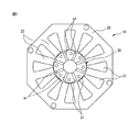
図1は本発明に基づく同期電動機の端面図である。図1に示される同期電動機10は、ステータ20と、ステータ20内に配置されたロータ30とを主に含んでいる。ステータ20は複数の電磁鋼板が積層されたステータコアを含んでいる。ステータ20の内周面には十二個のスロット21が等間隔で形成されている。隣接するスロット21の間のステータティース22には、コイル(図示しない)が絶縁紙を介して巻回されている。
Embodiments of the present invention will be described below with reference to the accompanying drawings. In the following drawings, the same members are denoted by the same reference numerals. In order to facilitate understanding, the scales of these drawings are appropriately changed.
FIG. 1 is an end view of a synchronous motor according to the present invention. A
図2は図1に示される同期電動機の部分拡大図である。図1および図2に示されるように、ロータ30は、八つの磁石m1と、これら磁石m1の間に配置されたロータヨーク31とを含んでいる。図2に示されるように、これら八つの磁石m1のそれぞれは断面矩形形状であり、それぞれが同期電動機10の半径方向に延びるよう配置されている。磁石m1の数は同期電動機10の極数に相当する。また、ロータヨーク31は一般に電磁鋼板の積層体からなり、これらを一体的に固定するためのタイロッド(図示しない)用の締結穴41がロータヨーク31の中心近傍に形成されている。
FIG. 2 is a partially enlarged view of the synchronous motor shown in FIG. As shown in FIGS. 1 and 2, the
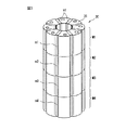
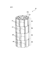
図3はロータの第一斜視図である。図3に示されるように、他の磁石m2が磁石m1に隣接して同期電動機10の軸線方向下側に配置されている。磁石m2は磁石m1と同一形状および同一磁力を有しており、その数は八つである。そのような八つの磁石m2は、磁石m1と同様に同期電動機10の軸線方向に延びるように配置されており、それぞれが磁石m1に隣接している。
FIG. 3 is a first perspective view of the rotor. As shown in FIG. 3, another magnet m <b> 2 is disposed on the lower side in the axial direction of the
また、他の磁石m3が、磁石m2に隣接して同期電動機10の軸線方向下側に配置されており、さらに別の磁石m4が、磁石m3に隣接して同期電動機10の軸線方向下側に配置されている。これら磁石m3、m4も磁石m2と同様に配置されている。以下、八つの磁石m1およびその関連部材を適宜、第一磁石群M1と呼ぶと共に、磁石m2、m3、m4およびその関連部材を適宜、第二磁石群M2、第三磁石群M3、第四磁石群M4とそれぞれ呼ぶこととする。後述するように、これら磁石群M1〜M4は同期電動機10の軸線方向周りに所望の角度位置で位置決めされるものとする。
Further, another magnet m3 is disposed on the lower side in the axial direction of the
このような同期電動機10において、ロータ30の磁石m1等の磁束がステータコアに磁界を発生させる。また、ステータ20のスロット21に巻回されたコイル(図示しない)に電流が流れると、電磁誘導により磁界が発生する。磁石m1等およびコイルには、角度に応じた磁束が発生し、これら磁束を乗算すると、一定のトルクが得られ、同期電動機10のロータ30が回転するようになる。
In such a
ところで、図4は一極分のロータ部分の拡大図である。図4においては、ロータ30のうちの一極分のロータヨーク31を示している。また、簡潔にする目的で、ステータ20の内周面29におけるスロット21の図示を省略している。図4に示されるように、同期電動機10の回転中心Oからロータヨーク31の中心を通る中心線を直線X0とする。そして、回転中心O周りに反時計回りに直線X0から角度θだけ回転させた直線を直線X1とする。
FIG. 4 is an enlarged view of the rotor portion for one pole. In FIG. 4, the
図4から分かるように、ロータヨーク31の外周面33は、その中心線X0近傍においてステータ20の内周面29に最接近し、ロータヨーク31の周方向両縁部近傍においてステータ20の内周面29から離間するように形成されている。具体的には、ロータヨーク31の外周面33の形状は以下の式(1)で示される三角関数により表される。
As can be seen from FIG. 4, the outer
Lg=G0/cos(Kc×θ) (1)
@ 式(1)において、Lgは、直線X1におけるロータヨーク31の外周面33とステータ20の内周面29との間のギャップ長である。G0は、中心線X0上におけるロータヨーク31の外周面33とステータ20の内周面29との間の最小ギャップである。また、Kcは曲率を定める係数である。なお、三角関数以外の関数を用いてロータヨーク31の外周面33を形成してもよい。また、ロータヨーク31の外周面33の一部分のみ、例えば中心部分のみを、そのような関数を用いて形成してもよい。そのような場合であっても、本発明の範囲に含まれる。
Lg = G0 / cos (Kc × θ) (1)
@ In Formula (1), Lg is the gap length between the outer
本発明では、ロータ30の外径形状を三角関数の曲線で構成しているので、低イナーシャ、大トルクで且つ回転が滑らかで、高速領域でも損失を抑えることができる。従って、本発明の同期電動機10を高頻度、高速でのピックアンドプレイス動作が要求される高速高応答のロボットに適用することも可能である。
In the present invention, since the outer diameter shape of the
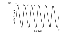
ここで、図5は、同期電動機を回転させたときの回転角度とコギングトルクとの間の関係を示す第一の図である。図5における横軸は回転角度θであり、縦軸はコギングトルクを示している。後述する他の図8、図12も同様である。また、図5で使用された同期電動機10は図1等に示される十二個スロットのステータ20と、図3に示されるロータ30とを含むものとする。つまり、図5で使用された同期電動機10のロータ30は、互いに同一角度で配置された第一磁石群M1から第四磁石群M4を含んでいる。
Here, FIG. 5 is a first diagram showing a relationship between the rotation angle and the cogging torque when the synchronous motor is rotated. In FIG. 5, the horizontal axis represents the rotation angle θ, and the vertical axis represents the cogging torque. The same applies to other FIGS. 8 and 12 described later. Further, the
このような八極十二個スロットの同期電動機10の場合には、図5に示されるように、一回転24回のメイン成分Pを含むコギングトルクが得られる。また、図5には、メイン成分Pに付随して2倍の48回成分である高調波成分Qも示されている。これらメイン成分Pおよび高調波成分Qが存在するために、同期電動機10を円滑に回転させるのは困難である。
In the case of the
これらメイン成分Pおよび高調波成分Qの大きさは、式(1)に示される係数Kcの値を変更することにより、調整される。しかしながら、係数Kcを変更した場合であっても、メイン成分Pおよび高調波成分Qの存在自体は解消することはできない。従って、同期電動機10を円滑に回転させるために、メイン成分Pおよび高調波成分Qの存在自体を解消する必要がある。
The magnitudes of the main component P and the harmonic component Q are adjusted by changing the value of the coefficient Kc shown in Expression (1). However, even if the coefficient Kc is changed, the presence of the main component P and the harmonic component Q itself cannot be eliminated. Accordingly, in order to smoothly rotate the
本発明の同期電動機10は八つの極と十二個のスロットとを備えており、それらの最小公倍数は24である。一回転360°を24で除算すると角度15°である。従って、図3に示される磁石群を15°の半分である7.5°だけ軸線方向周りに互いに離間させることにより、コギングトルクのメイン成分Pを排除することができる。
The
ここで、図6はロータヨークの第一の拡大図である。図6に示されるロータヨーク31aの締結穴41aは中心線X0から偏倚して形成されている。図示されるように、締結穴41aの中心と回転中心Oとを結ぶ線分X2と中心線X0とのなす角度θは3.75°である。本発明の第一の実施形態においては、このような締結穴41aが形成されたロータヨーク31aを使用する。
Here, FIG. 6 is a first enlarged view of the rotor yoke. The
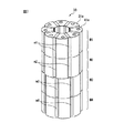
図7はロータの第二斜視図である。図7においては第一磁石群M1および第二磁石群M2においては締結穴41aが形成された八つのロータヨーク31aを用いて磁石m1、m2を固定する。これに対し、第三磁石群M3および第四磁石群M4においては、同一のロータヨーク31aをその表裏を逆にして磁石m3、m4を固定するのに使用する。
FIG. 7 is a second perspective view of the rotor. In FIG. 7, in the first magnet group M1 and the second magnet group M2, the magnets m1 and m2 are fixed using eight
その結果、図7に示されるように、第一磁石群M1および第二磁石群M2は一体的に、第三磁石群M3および第四磁石群M4に対して軸線方向周りに7.5°だけ回転して位置決めされるようになる。この回転角度7.5°は、第一磁石群M1および第二磁石群M2にて使用されるロータヨーク31aの締結穴41aの角度θ(=3.75°)の絶対値と、第三磁石群M3および第四磁石群M4にて使用されるロータヨーク31aの締結穴41aの角度θ(=−3.75°)の絶対値との和である。
As a result, as shown in FIG. 7, the first magnet group M1 and the second magnet group M2 are integrally formed by 7.5 ° around the axial direction with respect to the third magnet group M3 and the fourth magnet group M4. It rotates and comes to be positioned. The rotation angle 7.5 ° is the absolute value of the angle θ (= 3.75 °) of the
このようなロータ30と前述したステータ20とが組合わされた同期電動機10を使用した場合には、図5または図8に示される回転角度とコギングトルクとの間の関係が得られる。図5はメイン成分Pである1回転当り24回の成分とその倍の48回の高調波Qが載った図であり、図8はメイン成分Pの24回の成分のみが載った図である。磁極の形状などに応じて図5の波形または図8の波形が得られる。いずれの波形の場合でも三角関数の係数を変えることにより図14に示すようにコギングトルクの大きさが変化する。
図14において波形の振幅を最小にした場合でもまだ若干のコギングが残る。図7に示されるロータを採用することにより、コギングトルクをほとんど零にでき、従って、そのようなロータを備えた電動機をより円滑に回転させることができる。これにより1回転24回のメイン成分Pをほとんど零にすることができる。
さらに、第一の実施形態においては、ロータヨーク31aをその表裏を逆にして使用しているので、単一種類のロータヨーク31aのみでもって、7.5°だけズレたロータ30を作成することができる。なお、図6に示されるロータヨーク31aを用いることにより第一磁石群M1および第三磁石群M3を作成すると共に、同じロータヨーク31aをその表裏を逆にして用いることにより第二磁石群M2および第四磁石群M4を作成してもよい。
When the
In FIG. 14, even when the waveform amplitude is minimized, some cogging still remains. By adopting the rotor shown in FIG. 7, the cogging torque can be made almost zero, and therefore the electric motor equipped with such a rotor can be rotated more smoothly. As a result, the main component P for 24 revolutions can be made almost zero.
Furthermore, in the first embodiment, since the
次に、第二の実施形態について説明する。図9はロータヨークの第二の拡大図である。図9に示されるロータヨーク31bの締結穴41bは中心線X0から偏倚して形成されている。図示されるように、締結穴41bの中心と回転中心Oとを結ぶ線分X3と中心線X0とのなす角度θは1.875°である。
Next, a second embodiment will be described. FIG. 9 is a second enlarged view of the rotor yoke. The
さらに、図10はロータヨークの第三の拡大図である。図10に示されるロータヨーク31cの締結穴41cは中心線X0から偏倚して形成されている。図示されるように、締結穴41cの中心と回転中心Oとを結ぶ線分X4と中心線X0とのなす角度θは5.625°である。本発明の第二の実施形態においては、このような締結穴41a、41bが形成された二種類のロータヨーク31b、31cを使用する。
Further, FIG. 10 is a third enlarged view of the rotor yoke. The
図11はロータの第三斜視図である。図11においては第一磁石群M1においては締結穴41cが形成された八つのロータヨーク31cを図10の状態から表裏を逆にして用いることにより磁石m1を固定する。また、第二磁石群M2においては締結穴41bが形成された八つのロータヨーク31bを図9の状態から表裏を逆にして用いることにより磁石m2を固定する。
FIG. 11 is a third perspective view of the rotor. In FIG. 11, in the first magnet group M1, the magnet m1 is fixed by using the eight rotor yokes 31c formed with the fastening holes 41c in reverse from the state of FIG. Further, in the second magnet group M2, the magnet m2 is fixed by using the eight
さらに、第三磁石群M3においては締結穴41bが形成された八つのロータヨーク31bを用いて磁石m3を固定する。また、第四磁石群M4においては締結穴41cが形成された八つのロータヨーク31cを用いて磁石m4を固定する。
Further, in the third magnet group M3, the magnet m3 is fixed using eight
その結果、図11に示されるように、第一磁石群M1は、第二磁石群M2に対して軸線方向周りに3.75°(=−5.625°−(−1.875°)だけ回転して位置決めされる。同様に、第二磁石群M2は、第三磁石群M3に対して軸線方向周りに3.75°(=(−1.875°)−1.875°)だけ回転して位置決めされる。また、第三磁石群M3は、第四磁石群M4に対して軸線方向周りに3.75°(=1.875°−5.625°)だけ回転して位置決めされる。 As a result, as shown in FIG. 11, the first magnet group M1 is 3.75 ° (= −5.625 ° − (− 1.875 °)) around the axial direction with respect to the second magnet group M2. Similarly, the second magnet group M2 is rotated by 3.75 ° (= (− 1.875 °) −1.875 °) around the axial direction with respect to the third magnet group M3. Further, the third magnet group M3 is positioned by rotating by 3.75 ° (= 1.875 ° −5.625 °) around the axial direction with respect to the fourth magnet group M4. .
このようなロータ30と前述したステータ20とが組合わされた第二の実施形態の同期電動機10を使用した場合には、図12に示される回転角度とコギングトルクとの間の関係が得られる。図12においては、メイン成分Pおよび高調波成分Qが排除され、その結果、コギングトルクは発生しないようになる。従って、図5および図8の場合と比較すると、図11に示されるロータ30を備えた同期電動機10を更に円滑に回転させられるのが分かるであろう。
When the
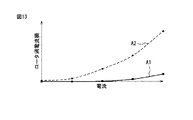
さらに、図13は電流とロータ渦電流損との間の関係を示す図である。図13において横軸は電流を示すと共に、縦軸はロータ渦電流損を示している。また、図13における実線A1は本発明における八極十二個スロットの同期電動機10の挙動を示すと共に、破線A2は十極十二個スロットの同期電動機の挙動を示している。
Further, FIG. 13 is a diagram showing the relationship between current and rotor eddy current loss. In FIG. 13, the horizontal axis represents current, and the vertical axis represents rotor eddy current loss. A solid line A1 in FIG. 13 shows the behavior of the
図13で破線A2によりに示されるように、電流が大きくなると、十極十二個スロットの同期電動機のロータ渦電流損も大きくなる。これに対し、実線A1で示されるように、本発明の八極十二個スロットの同期電動機10においては、電流が大きくなったとしても、ロータ渦電流損はほとんど変化しない。従って、八極十二個スロットの構成は、ロータ渦電流損の増加を抑えるのに極めて有利であるのが分かるであろう。
As indicated by the broken line A2 in FIG. 13, when the current increases, the rotor eddy current loss of the synchronous motor with 12 poles and 12 slots also increases. On the other hand, as indicated by the solid line A1, in the
ここで、図4を再び参照すると、図4にはステータ20の内周面29とロータヨーク31の外周面33との間の最大ギャップGmも示されている。そして、図14は最大ギャップ/最小ギャップとコギングトルクとの間の関係を示す図である。図14においては横軸は比Gm/G0を表すと共に、縦軸はコギングトルクを示している。ここで、本願明細書においては、最大ギャップGmと最小ギャップG0との比Gm/G0を曲率と呼ぶ場合がある。
Here, referring again to FIG. 4, the maximum gap Gm between the inner
図14に示されるように、比Gm/G0が数値5に向かって増大するにつれて、コギングトルクは減少する。そして、比Gm/G0が数値5から更に増大すると、コギングトルクは増大する。つまり、比Gm/G0が数値5であるときに、コギングトルクは最小値となる。従って、比Gm/G0が数値5になるように最大ギャップ量Gmおよび最小ギャップ量G0が設定されたロータ30を使用することにより、コギングトルクを最小限に抑えることができる。
As shown in FIG. 14, as the ratio Gm / G0 increases toward the
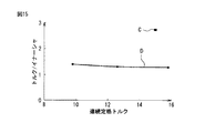
ところで、高頻度、高速でのピックアンドプレイス動作が要求される高速高応答のロボット内で同期電動機10が使用される場合には、同期電動機10の連続定格トルクとイナーシャとの比(トルク/イナーシャ)が大きいことが要求される。図15は連続定格トルクとトルク/イナーシャとの間の関係を示す図である。図15においては横軸は連続定格トルクを表すと共に、縦軸はトルク/イナーシャを表している。また、図15においては、点Cは本発明の同期電動機10を示しており、実線Dは既存のモータの挙動を示している。
By the way, when the
図15においては、本発明の同期電動機10のトルク/イナーシャを示す点Cは、既存のモータの挙動を示す実線Dよりも高い値を示している。つまり、本発明の同期電動機10は既存のモータよりも大幅に性能が高いことが分かるであろう。従って、本発明の同期電動機10を高頻度、高速でのピックアンドプレイス動作が要求される高速高応答のロボット内で使用することも可能である。
In FIG. 15, the point C indicating the torque / inertia of the
10 同期電動機
20 ステータ
21 スロット
22 ステータティース
29 内周面
30 ロータ
31、31a、31b、31c ロータヨーク
33 外周面
41、41a、41b、41c 締結穴
m1、m2、m3、m4 磁石
M1 第一磁石群
M2 第二磁石群
M3 第三磁石群
M4 第四磁石群
DESCRIPTION OF
前述した目的を達成するために1番目の発明によれば、十二個のスロットが形成された集中巻ステータと、該集中巻きステータの内側に配置されていて八つの磁石が半径方向に配置された八極のロータと、を具備し、前記ロータの一極分の外形形状の一部分または全体を、三角関数の曲線で構成しており、前記ロータの半径方向に延びるロータヨークの中心線に沿った前記ロータヨークの外周面と前記ステータの内周面との間の最小距離に対する、前記ロータの半径方向における前記ロータヨークの前記外周面と前記ステータの前記内周面との間の最大距離の比はコギングトルクが最小になるように選択されるようにした同期電動機が提供される。
2番目の発明によれば、1番目の発明において、前記ロータの一極分の外形形状の前記一部分が前記ロータの一極分の外形形状の中心部分であるようにした。
3番目の発明によれば、1番目または2番目の発明において、前記ロータは、半径方向に配置された八つの磁石からなる第一磁石群と、前記同期電動機の軸線方向において前記第一磁石群に隣接して配置されていて半径方向に配置された八つの磁石からなる第二磁石群とを含んでおり、前記第一磁石群と前記第二磁石群とが前記同期電動機の軸線方向周りに互いに7.5°だけズレているようにした。
4番目の発明によれば、1番目または2番目の発明において、前記ロータは、半径方向に配置された八つの磁石からなる第一磁石群と、前記同期電動機の軸線方向において前記第一磁石群に隣接して配置されていて半径方向に配置された八つの磁石からなる第二磁石群と、前記同期電動機の軸線方向において前記第二磁石群に隣接して配置されていて半径方向に配置された八つの磁石からなる第三磁石群とを含んでおり、前記同期電動機の軸線方向において前記第三磁石群に隣接して配置されていて半径方向に配置された八つの磁石からなる第四磁石群とを含んでおり、前記第一磁石群から前記第四磁石群のうち互いに隣接する二つの磁石群は前記同期電動機の軸線方向周りに互いに3.75°だけズレているようにした。
5番目の発明によれば、3番目の発明において、前記ロータにおける前記第一磁石群の第一ロータヨークには、前記ロータの各極に対応する部分の中心線から前記同期電動機の軸線方向周りに3.75°だけズレた位置に第一締結穴が形成されており、前記ロータにおける前記第二磁石群の第二ロータヨークには、前記ロータの各極に対応する部分の中心線から前記同期電動機の軸線方向周りで且つ前記第一締結穴とは反対方向に3.75°だけズレた位置に第二締結穴が形成されている。
6番目の発明によれば、4番目の発明において、前記ロータにおける前記第一磁石群の第一ロータヨークには、前記ロータの各極に対応する部分の中心線から前記同期電動機の軸線方向周りに5.625°だけズレた位置に第一締結穴が形成されており、前記ロータにおける前記第二磁石群の第二ロータヨークには、前記ロータの各極に対応する部分の中心線から前記同期電動機の軸線方向周りで且つ前記第一締結穴と同一方向に1.875°だけズレた位置に第二締結穴が形成されており、前記ロータにおける前記第三磁石群の第三ロータヨークには、前記ロータの各極に対応する部分の中心線から前記同期電動機の軸線方向周りで且つ前記第一締結穴と反対方向に1.875°だけズレた位置に第三締結穴がそれぞれ形成されており、前記ロータにおける前記第四磁石群の第四ロータヨークには、前記ロータの各極に対応する部分の中心線から前記同期電動機の軸線方向周りで且つ前記第一締結穴と反対方向に5.625°だけズレた位置に第四締結穴がそれぞれ形成されている。
7番目の発明によれば、1番目の発明において、前記比は4.5と5.5の間の値であるようにした。
In order to achieve the above-described object, according to the first invention, a concentrated winding stator having twelve slots, and eight magnets arranged radially inside the concentrated winding stator are arranged. equipped with eight pole rotor, and a part, or all, of the pole portion of the outer shape of the rotor constitute in curves of a trigonometric function, along the center line of the rotor yoke extending in the radial direction of the rotor The ratio of the maximum distance between the outer peripheral surface of the rotor yoke and the inner peripheral surface of the stator in the radial direction of the rotor to the minimum distance between the outer peripheral surface of the rotor yoke and the inner peripheral surface of the stator is A synchronous motor is provided that is selected to minimize cogging torque .
According to the second invention, in the first invention, the part of the outer shape of one pole of the rotor is a central portion of the outer shape of one pole of the rotor.
According to a third invention, in the first or second invention, the rotor comprises a first magnet group comprising eight magnets arranged in a radial direction, and the first magnet group in the axial direction of the synchronous motor. And a second magnet group consisting of eight magnets arranged in the radial direction, and the first magnet group and the second magnet group are arranged around the axial direction of the synchronous motor. It was shifted by 7.5 ° from each other.
According to a fourth invention, in the first or second invention, the rotor comprises a first magnet group consisting of eight magnets arranged in the radial direction, and the first magnet group in the axial direction of the synchronous motor. A second magnet group consisting of eight magnets arranged adjacent to each other in the radial direction, and arranged adjacent to the second magnet group in the axial direction of the synchronous motor and arranged in the radial direction. And a fourth magnet composed of eight magnets arranged in the radial direction adjacent to the third magnet group in the axial direction of the synchronous motor. The two magnet groups adjacent to each other from the first magnet group to the fourth magnet group are shifted from each other by 3.75 ° around the axial direction of the synchronous motor.
According to a fifth aspect, in the third aspect, the first rotor yoke of the first magnet group in the rotor is arranged around the axial direction of the synchronous motor from the center line of the portion corresponding to each pole of the rotor. A first fastening hole is formed at a position shifted by 3.75 °, and the synchronous motor is connected to the second rotor yoke of the second magnet group in the rotor from the center line of the portion corresponding to each pole of the rotor. The second fastening hole is formed at a position that is shifted by 3.75 ° in the opposite direction to the first fastening hole.
According to a sixth invention, in the fourth invention, the first rotor yoke of the first magnet group in the rotor is arranged around the axial direction of the synchronous motor from the center line of the portion corresponding to each pole of the rotor. A first fastening hole is formed at a position shifted by 5.625 °, and the second motor yoke of the second magnet group in the rotor is connected to the synchronous motor from a center line of a portion corresponding to each pole of the rotor. The second fastening hole is formed at a position shifted by 1.875 ° in the same direction as the first fastening hole, and the third rotor yoke of the third magnet group in the rotor has the Third fastening holes are respectively formed at positions shifted by 1.875 ° around the axial direction of the synchronous motor from the center line of the portion corresponding to each pole of the rotor and in the opposite direction to the first fastening hole, Above The fourth rotor yoke of the fourth magnet group in the motor is 5.625 ° around the axial direction of the synchronous motor and in the direction opposite to the first fastening hole from the center line of the portion corresponding to each pole of the rotor. A fourth fastening hole is formed at a position shifted by a distance.
According to a seventh aspect, in the first aspect, the ratio is between 4.5 and 5.5.
Claims (6)
該集中巻きステータの内側に配置されていて八つの磁石が半径方向に配置された八極のロータと、を具備し、前記ロータの一極分の外形形状の一部分または全体を、三角関数の曲線およびこれに近似した曲線で構成した同期電動機。 A concentrated stator having twelve slots formed;
An octupole rotor arranged inside the concentrated winding stator and having eight magnets arranged in a radial direction, and a part or all of the outer shape of one pole of the rotor is a curve of a trigonometric function And a synchronous motor composed of a curve approximated thereto.
前記第一磁石群と前記第二磁石群とが前記同期電動機の軸線方向周りに互いに7.5°だけズレているようにした請求項1または2に記載の同期電動機。 The rotor includes a first magnet group including eight magnets arranged in the radial direction, and eight magnets arranged in the radial direction adjacent to the first magnet group in the axial direction of the synchronous motor. A second magnet group consisting of
3. The synchronous motor according to claim 1, wherein the first magnet group and the second magnet group are shifted from each other by 7.5 ° around the axial direction of the synchronous motor.
前記第一磁石群から前記第四磁石群のうち互いに隣接する二つの磁石群は前記同期電動機の軸線方向周りに互いに3.75°だけズレているようにした請求項1または2に記載の同期電動機。 The rotor includes a first magnet group including eight magnets arranged in the radial direction, and eight magnets arranged in the radial direction adjacent to the first magnet group in the axial direction of the synchronous motor. And a third magnet group consisting of eight magnets arranged adjacent to the second magnet group in the axial direction of the synchronous motor and arranged radially. A fourth magnet group consisting of eight magnets arranged adjacent to the third magnet group in the axial direction of the synchronous motor and arranged radially.
3. The synchronization according to claim 1, wherein two magnet groups adjacent to each other from the first magnet group to the fourth magnet group are shifted from each other by 3.75 ° around the axial direction of the synchronous motor. Electric motor.
前記ロータにおける前記第二磁石群の第二ロータヨークには、前記ロータの各極に対応する部分の中心線から前記同期電動機の軸線方向周りで且つ前記第一締結穴とは反対方向に3.75°だけズレた位置に第二締結穴が形成されている、請求項3に記載の同期電動機。 The first rotor yoke of the first magnet group in the rotor has a first fastening hole at a position shifted by 3.75 ° around the axial direction of the synchronous motor from the center line of the portion corresponding to each pole of the rotor. Formed,
The second rotor yoke of the second magnet group in the rotor is 3.75 around the axial direction of the synchronous motor from the center line of the portion corresponding to each pole of the rotor and in the direction opposite to the first fastening hole. The synchronous motor according to claim 3, wherein a second fastening hole is formed at a position shifted by °.
前記ロータにおける前記第二磁石群の第二ロータヨークには、前記ロータの各極に対応する部分の中心線から前記同期電動機の軸線方向周りで且つ前記第一締結穴と同一方向に1.875°だけズレた位置に第二締結穴が形成されており、
前記ロータにおける前記第三磁石群の第三ロータヨークには、前記ロータの各極に対応する部分の中心線から前記同期電動機の軸線方向周りで且つ前記第一締結穴と反対方向に1.875°だけズレた位置に第三締結穴がそれぞれ形成されており、
前記ロータにおける前記第四磁石群の第四ロータヨークには、前記ロータの各極に対応する部分の中心線から前記同期電動機の軸線方向周りで且つ前記第一締結穴と反対方向に5.625°だけズレた位置に第四締結穴がそれぞれ形成されている、請求項4に記載の同期電動機。 The first rotor yoke of the first magnet group in the rotor has a first fastening hole at a position displaced by 5.625 ° around the axial direction of the synchronous motor from the center line of the portion corresponding to each pole of the rotor. Formed,
The second rotor yoke of the second magnet group in the rotor has 1.875 ° around the axial direction of the synchronous motor from the center line of the portion corresponding to each pole of the rotor and in the same direction as the first fastening hole. A second fastening hole is formed at a position that is only shifted,
The third rotor yoke of the third magnet group in the rotor is 1.875 ° around the axial direction of the synchronous motor from the center line of the portion corresponding to each pole of the rotor and in the direction opposite to the first fastening hole. The third fastening hole is formed at the position that is only shifted,
The fourth rotor yoke of the fourth magnet group in the rotor is 5.625 ° around the axial direction of the synchronous motor and in the direction opposite to the first fastening hole from the center line of the portion corresponding to each pole of the rotor. The synchronous motor according to claim 4, wherein the fourth fastening holes are respectively formed at positions shifted by a certain amount.
Priority Applications (3)
| Application Number | Priority Date | Filing Date | Title |
|---|---|---|---|
| JP2014023774A JP2014180193A (en) | 2013-02-15 | 2014-02-10 | Synchronous motor with high responsiveness |
| CN201410051732.3A CN103997141A (en) | 2013-02-15 | 2014-02-14 | Synchronous motor with high responsiveness |
| DE201410002100 DE102014002100A1 (en) | 2013-02-15 | 2014-02-14 | Synchronous motor for use as servo motor in e.g. vehicle, has rotor that is formed of portion or whole outer contour, which corresponds to pole, in curved shape by trigonometric function or approximated by trigonometric function |
Applications Claiming Priority (3)
| Application Number | Priority Date | Filing Date | Title |
|---|---|---|---|
| JP2013027836 | 2013-02-15 | ||
| JP2013027836 | 2013-02-15 | ||
| JP2014023774A JP2014180193A (en) | 2013-02-15 | 2014-02-10 | Synchronous motor with high responsiveness |
Publications (1)
| Publication Number | Publication Date |
|---|---|
| JP2014180193A true JP2014180193A (en) | 2014-09-25 |
Family
ID=51264000
Family Applications (1)
| Application Number | Title | Priority Date | Filing Date |
|---|---|---|---|
| JP2014023774A Pending JP2014180193A (en) | 2013-02-15 | 2014-02-10 | Synchronous motor with high responsiveness |
Country Status (3)
| Country | Link |
|---|---|
| JP (1) | JP2014180193A (en) |
| CN (1) | CN103997141A (en) |
| DE (1) | DE102014002100A1 (en) |
Families Citing this family (5)
| Publication number | Priority date | Publication date | Assignee | Title |
|---|---|---|---|---|
| NL2013403B1 (en) * | 2014-09-02 | 2016-09-26 | Elsio Cicilia Beremundo | Synchronous rotary motor or generator provided with various rotors and / or stators. |
| FR3049407B1 (en) * | 2016-03-25 | 2018-03-16 | Valeo Equipements Electriques Moteur | ROTATING ELECTRIC MACHINE HAVING A DIMENSION RATIO MINIMIZING TORQUE CORRUGATIONS |
| FR3049406B1 (en) * | 2016-03-25 | 2018-03-16 | Valeo Equipements Electriques Moteur | ROTATING ELECTRIC MACHINE HAVING CONFIGURATION MINIMIZING TORQUE CORRUGATIONS |
| CN110168878B (en) | 2017-01-04 | 2022-01-28 | Lg伊诺特有限公司 | Motor and transmission |
| CN108832743B (en) * | 2018-07-25 | 2024-01-16 | 威灵(芜湖)电机制造有限公司 | Rotor punching sheet, rotor core and motor |
Citations (8)
| Publication number | Priority date | Publication date | Assignee | Title |
|---|---|---|---|---|
| JPS63178750A (en) * | 1987-01-17 | 1988-07-22 | Fanuc Ltd | Structure of rotor for synchronous ac servomotor |
| JPH08851U (en) * | 1995-11-24 | 1996-05-21 | ファナック株式会社 | 8-pole rotor of three-phase AC synchronous motor |
| JP2008029078A (en) * | 2006-07-19 | 2008-02-07 | Fanuc Ltd | Permanent magnet type synchronous motor |
| JP2008048481A (en) * | 2006-08-11 | 2008-02-28 | Toshiba Corp | Permanent magnet motor |
| WO2008078584A1 (en) * | 2006-12-27 | 2008-07-03 | Kabushiki Kaisha Yaskawa Denki | Buried magnet motor |
| WO2009084151A1 (en) * | 2007-12-28 | 2009-07-09 | Mitsubishi Electric Corporation | Rotating electric machine |
| JP2010094001A (en) * | 2008-10-10 | 2010-04-22 | Asmo Co Ltd | Rotor structure for rotating electrical machine |
| JP2010531130A (en) * | 2007-06-25 | 2010-09-16 | ローベルト ボツシユ ゲゼルシヤフト ミツト ベシユレンクテル ハフツング | Synchronous motor having 12 stator teeth and 10 rotor poles |
Family Cites Families (1)
| Publication number | Priority date | Publication date | Assignee | Title |
|---|---|---|---|---|
| JP3513467B2 (en) | 2000-06-16 | 2004-03-31 | ファナック株式会社 | Synchronous motor rotor |
-
2014
- 2014-02-10 JP JP2014023774A patent/JP2014180193A/en active Pending
- 2014-02-14 DE DE201410002100 patent/DE102014002100A1/en not_active Withdrawn
- 2014-02-14 CN CN201410051732.3A patent/CN103997141A/en active Pending
Patent Citations (8)
| Publication number | Priority date | Publication date | Assignee | Title |
|---|---|---|---|---|
| JPS63178750A (en) * | 1987-01-17 | 1988-07-22 | Fanuc Ltd | Structure of rotor for synchronous ac servomotor |
| JPH08851U (en) * | 1995-11-24 | 1996-05-21 | ファナック株式会社 | 8-pole rotor of three-phase AC synchronous motor |
| JP2008029078A (en) * | 2006-07-19 | 2008-02-07 | Fanuc Ltd | Permanent magnet type synchronous motor |
| JP2008048481A (en) * | 2006-08-11 | 2008-02-28 | Toshiba Corp | Permanent magnet motor |
| WO2008078584A1 (en) * | 2006-12-27 | 2008-07-03 | Kabushiki Kaisha Yaskawa Denki | Buried magnet motor |
| JP2010531130A (en) * | 2007-06-25 | 2010-09-16 | ローベルト ボツシユ ゲゼルシヤフト ミツト ベシユレンクテル ハフツング | Synchronous motor having 12 stator teeth and 10 rotor poles |
| WO2009084151A1 (en) * | 2007-12-28 | 2009-07-09 | Mitsubishi Electric Corporation | Rotating electric machine |
| JP2010094001A (en) * | 2008-10-10 | 2010-04-22 | Asmo Co Ltd | Rotor structure for rotating electrical machine |
Also Published As
| Publication number | Publication date |
|---|---|
| CN103997141A (en) | 2014-08-20 |
| DE102014002100A1 (en) | 2014-08-21 |
Similar Documents
| Publication | Publication Date | Title |
|---|---|---|
| US7569962B2 (en) | Multi-phase brushless motor with reduced number of stator poles | |
| JP5778498B2 (en) | Stator and motor | |
| JP6161707B2 (en) | Synchronous motor | |
| JP5376016B1 (en) | Rotating electric machine | |
| JP2012228104A (en) | Permanent magnet-embedded motor | |
| JP2014180193A (en) | Synchronous motor with high responsiveness | |
| JP2010284035A (en) | Permanent magnet rotating electrical machine | |
| JP2012115070A (en) | Rotary electric machine | |
| JP5483582B2 (en) | motor | |
| JP2009027849A (en) | Permanent magnet type rotary electric machine | |
| JP2013207857A (en) | Brushless motor | |
| JP2012080697A (en) | Motor | |
| JP6990014B2 (en) | Rotating machine | |
| JP6012046B2 (en) | Brushless motor | |
| JP2013128378A (en) | Permanent magnet type rotary electric machine | |
| JP5491344B2 (en) | motor | |
| JPWO2014115278A1 (en) | Synchronous motor | |
| JP5687072B2 (en) | motor | |
| JP5587683B2 (en) | motor | |
| EP4329152A1 (en) | Rotor | |
| JP6100538B2 (en) | motor | |
| JP5611094B2 (en) | Rotating electric machine | |
| JP2018125993A (en) | Rotary electric machine | |
| JP2012139102A (en) | Permanent magnet rotary electric machine | |
| JP2014158396A (en) | Synchronous motor stator |
Legal Events
| Date | Code | Title | Description |
|---|---|---|---|
| A131 | Notification of reasons for refusal |
Free format text: JAPANESE INTERMEDIATE CODE: A131 Effective date: 20140701 |
|
| A521 | Written amendment |
Free format text: JAPANESE INTERMEDIATE CODE: A523 Effective date: 20140723 |
|
| A02 | Decision of refusal |
Free format text: JAPANESE INTERMEDIATE CODE: A02 Effective date: 20141007 |