JP2013115904A - Combined mechano-electric electric driving apparatus - Google Patents
Combined mechano-electric electric driving apparatus Download PDFInfo
- Publication number
- JP2013115904A JP2013115904A JP2011259229A JP2011259229A JP2013115904A JP 2013115904 A JP2013115904 A JP 2013115904A JP 2011259229 A JP2011259229 A JP 2011259229A JP 2011259229 A JP2011259229 A JP 2011259229A JP 2013115904 A JP2013115904 A JP 2013115904A
- Authority
- JP
- Japan
- Prior art keywords
- housing
- drive device
- electric drive
- stator
- stator core
- Prior art date
- Legal status (The legal status is an assumption and is not a legal conclusion. Google has not performed a legal analysis and makes no representation as to the accuracy of the status listed.)
- Pending
Links
Images


Classifications
-
- H—ELECTRICITY
- H02—GENERATION; CONVERSION OR DISTRIBUTION OF ELECTRIC POWER
- H02K—DYNAMO-ELECTRIC MACHINES
- H02K11/00—Structural association of dynamo-electric machines with electric components or with devices for shielding, monitoring or protection
- H02K11/02—Structural association of dynamo-electric machines with electric components or with devices for shielding, monitoring or protection for suppression of electromagnetic interference
-
- H—ELECTRICITY
- H02—GENERATION; CONVERSION OR DISTRIBUTION OF ELECTRIC POWER
- H02K—DYNAMO-ELECTRIC MACHINES
- H02K11/00—Structural association of dynamo-electric machines with electric components or with devices for shielding, monitoring or protection
- H02K11/30—Structural association with control circuits or drive circuits
- H02K11/33—Drive circuits, e.g. power electronics
-
- H—ELECTRICITY
- H02—GENERATION; CONVERSION OR DISTRIBUTION OF ELECTRIC POWER
- H02K—DYNAMO-ELECTRIC MACHINES
- H02K11/00—Structural association of dynamo-electric machines with electric components or with devices for shielding, monitoring or protection
- H02K11/40—Structural association with grounding devices
-
- H—ELECTRICITY
- H02—GENERATION; CONVERSION OR DISTRIBUTION OF ELECTRIC POWER
- H02K—DYNAMO-ELECTRIC MACHINES
- H02K3/00—Details of windings
- H02K3/04—Windings characterised by the conductor shape, form or construction, e.g. with bar conductors
- H02K3/28—Layout of windings or of connections between windings
-
- H—ELECTRICITY
- H02—GENERATION; CONVERSION OR DISTRIBUTION OF ELECTRIC POWER
- H02K—DYNAMO-ELECTRIC MACHINES
- H02K5/00—Casings; Enclosures; Supports
- H02K5/04—Casings or enclosures characterised by the shape, form or construction thereof
- H02K5/22—Auxiliary parts of casings not covered by groups H02K5/06-H02K5/20, e.g. shaped to form connection boxes or terminal boxes
-
- H—ELECTRICITY
- H02—GENERATION; CONVERSION OR DISTRIBUTION OF ELECTRIC POWER
- H02M—APPARATUS FOR CONVERSION BETWEEN AC AND AC, BETWEEN AC AND DC, OR BETWEEN DC AND DC, AND FOR USE WITH MAINS OR SIMILAR POWER SUPPLY SYSTEMS; CONVERSION OF DC OR AC INPUT POWER INTO SURGE OUTPUT POWER; CONTROL OR REGULATION THEREOF
- H02M1/00—Details of apparatus for conversion
- H02M1/12—Arrangements for reducing harmonics from ac input or output
-
- H—ELECTRICITY
- H02—GENERATION; CONVERSION OR DISTRIBUTION OF ELECTRIC POWER
- H02M—APPARATUS FOR CONVERSION BETWEEN AC AND AC, BETWEEN AC AND DC, OR BETWEEN DC AND DC, AND FOR USE WITH MAINS OR SIMILAR POWER SUPPLY SYSTEMS; CONVERSION OF DC OR AC INPUT POWER INTO SURGE OUTPUT POWER; CONTROL OR REGULATION THEREOF
- H02M7/00—Conversion of ac power input into dc power output; Conversion of dc power input into ac power output
- H02M7/003—Constructional details, e.g. physical layout, assembly, wiring or busbar connections
-
- H—ELECTRICITY
- H02—GENERATION; CONVERSION OR DISTRIBUTION OF ELECTRIC POWER
- H02M—APPARATUS FOR CONVERSION BETWEEN AC AND AC, BETWEEN AC AND DC, OR BETWEEN DC AND DC, AND FOR USE WITH MAINS OR SIMILAR POWER SUPPLY SYSTEMS; CONVERSION OF DC OR AC INPUT POWER INTO SURGE OUTPUT POWER; CONTROL OR REGULATION THEREOF
- H02M7/00—Conversion of ac power input into dc power output; Conversion of dc power input into ac power output
- H02M7/42—Conversion of dc power input into ac power output without possibility of reversal
- H02M7/44—Conversion of dc power input into ac power output without possibility of reversal by static converters
- H02M7/48—Conversion of dc power input into ac power output without possibility of reversal by static converters using discharge tubes with control electrode or semiconductor devices with control electrode
- H02M7/53—Conversion of dc power input into ac power output without possibility of reversal by static converters using discharge tubes with control electrode or semiconductor devices with control electrode using devices of a triode or transistor type requiring continuous application of a control signal
- H02M7/537—Conversion of dc power input into ac power output without possibility of reversal by static converters using discharge tubes with control electrode or semiconductor devices with control electrode using devices of a triode or transistor type requiring continuous application of a control signal using semiconductor devices only, e.g. single switched pulse inverters
- H02M7/5387—Conversion of dc power input into ac power output without possibility of reversal by static converters using discharge tubes with control electrode or semiconductor devices with control electrode using devices of a triode or transistor type requiring continuous application of a control signal using semiconductor devices only, e.g. single switched pulse inverters in a bridge configuration
-
- H—ELECTRICITY
- H02—GENERATION; CONVERSION OR DISTRIBUTION OF ELECTRIC POWER
- H02M—APPARATUS FOR CONVERSION BETWEEN AC AND AC, BETWEEN AC AND DC, OR BETWEEN DC AND DC, AND FOR USE WITH MAINS OR SIMILAR POWER SUPPLY SYSTEMS; CONVERSION OF DC OR AC INPUT POWER INTO SURGE OUTPUT POWER; CONTROL OR REGULATION THEREOF
- H02M1/00—Details of apparatus for conversion
- H02M1/12—Arrangements for reducing harmonics from ac input or output
- H02M1/123—Suppression of common mode voltage or current
Abstract
Description
本発明は、回転電機とそれを駆動するための電力変換装置とが一体に設けられた機電一体型の電動駆動装置に関する。 The present invention relates to an electromechanical integrated electric drive device in which a rotating electrical machine and a power conversion device for driving the rotating electrical machine are integrally provided.
コモンモードノイズ低減機構を備えた電力変換装置の一例が特許文献1に記載されている。コモンモードノイズ(コモンモード電流とも呼ばれる)は回転電機を制御する電力変換装置の誤動作原因となるため、コモンモードノイズを低減することが望ましい。例えば、回転電機が発生する回転トルクにより車両を走行する電気自動車やエンジンと回転電機両方の出力に基づいて走行するハイブリット自動車では、コモンモードノイズが車両走行に悪影響を及ぼすため、コモンモードノイズを低減することが望ましい。また、車両への搭載性を考えると、電力変化装置と回転電機とが一体化された機電一体型電動駆動装置であることが望ましい。
An example of a power converter provided with a common mode noise reduction mechanism is described in
しかしながら、特許文献1に記載の発明では、コモンモード電流を低減するために特別なノイズ低減回路を追加しているために、コストアップを招くと共に電力変換装置も大きくなる。さらに、電力変換装置の制御も複雑になるという課題がある。
However, in the invention described in
請求項1の発明は、ロータ、電機子巻線が装着されたステータコアを有するステータ、および、電機子巻線の交流端子が配置されステータを保持するハウジングが設けられた回転電機と、インバータ回路および該インバータ回路と交流端子とを接続する交流バスバーを有し、ハウジングの外周に固定される電力変換装置と、を備えた機電一体型の電動駆動装置であって、ステータコアに接触して設けられ、ステータの浮遊容量に起因するコモンモード電流を集電する集電体と、インバータ回路の直流入力側の仮想中性点と集電体とを接続する接続配線と、を備えたことを特徴とする。
The invention of
本発明によれば、コモンモード電流を、機電一体型の電動駆動装置内において回転電機側から電力変換装置の仮想中性点へと戻すことができ、コモンモード電流の影響を抑制することができる。 According to the present invention, the common mode current can be returned from the rotating electrical machine side to the virtual neutral point of the power converter in the electromechanical integrated electric drive device, and the influence of the common mode current can be suppressed. .
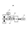
以下、図を参照して本発明を実施するための形態について説明する。図1は、ハイブリッド自動車(以下「HEV」と記述する)の制御ブロックを示す図である。なお、以下ではエンジンと回転電機両方の出力に基づいて走行するハイブリット自動車を例に説明するが、本実施の形態の機電一体型の電動駆動装置は、回転電機が発生する回転トルクにより車両を走行する電気自動車にも適用が可能である。 Hereinafter, embodiments for carrying out the present invention will be described with reference to the drawings. FIG. 1 is a diagram showing a control block of a hybrid vehicle (hereinafter referred to as “HEV”). In the following description, a hybrid vehicle that travels based on the outputs of both the engine and the rotating electrical machine will be described as an example. However, the electromechanical integrated electric drive device of the present embodiment travels a vehicle by rotational torque generated by the rotating electrical machine. It can also be applied to electric vehicles.
エンジンEGNおよび回転電機900は車両の走行用トルクを発生する。また、回転電機900は回転トルクを発生するだけでなく、回転電機900に外部から加えられる機械エネルギーを電力に変換する機能を有する。回転電機900は、例えば同期機あるいは誘導機であり、上述のごとく、運転方法によりモータとしても発電機としても動作する。回転電機900を自動車に搭載する場合には、小型で高出力を得ることが望ましく、ネオジウムなどの磁石を使用した永久磁石型の同期電動機が適している。また、永久磁石型の同期電動機は誘導電動機に比べて回転子の発熱が少なく、この観点でも自動車用として優れている。
Engine EGN and rotating
エンジンEGNの出力トルクは動力分配機構TSMを介して回転電機900に伝達され、動力分配機構TSMからの回転トルクあるいは回転電機900が発生する回転トルクは、トランスミッションTMおよびデファレンシャルギアDEFを介して車輪に伝達される。一方、回生制動の運転時には、車輪から回転トルクが回転電機900に伝達され、供給された回転トルクに基づいて交流電力を発生する。発生した交流電力は後述するように電力変換装置200により直流電力に変換され、高電圧用のバッテリ136を充電し、充電された電力は再び走行エネルギーとして使用される。
The output torque of the engine EGN is transmitted to the rotating
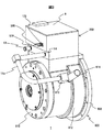
図2、3は本実施の形態の機電一体型電動駆動装置の外観斜視図である。電動駆動装置1は、図1に示した回転電機900と電力変換装置200とを一体構造としたものである。回転電機900は外装部品としてハウジング912、フロントブラケット908、リヤブラケット910を有しており、それらは、通常アルミに代表される金属のダイカストや鋳造で作られる。
2 and 3 are external perspective views of the electromechanical integrated electric drive device of the present embodiment. The
回転電機900のハウジング912の軸方向両端にはフロントブラケット908、リヤブラケット910が設けられており、フロントブラケット908の中央からはロータシャフト920が突出している。電力変換装置200は、回転電機900の径方向位置であるハウジング912の外周面に固定されている。
A
電力変換装置200を構成する回路部品が収納されるケース12は、略立方体形状を有しており、上部開口部に蓋8が固定されている。ケース12は、回転電機900のハウジング912上に固定されている。ケース12の材料は導電性材料であり、本実施の形態ではアルミダイカスト等の金属材料としている。電力変換装置200と車両側に設けられた上位の制御装置との信号送受信は、コネクタ21を介して行われる。
The
電力変換装置200のケース12に設けられた穴12jからは正極側の電源端子509および負極側の電源端子508が突出しており、バッテリ136からの直流電力はこれらの電源端子508,509に供給される。ケース12には冷媒を流すための流路が形成されており、冷媒はケース12の側壁に設けられた入口配管13から流入し、出口配管14から排出される。ケース12に設けられた3相インバータ回路等の電子部品は、冷媒によって冷却される。
A positive
ケース12の出口配管14は、中継部材14aを介して回転電機900のハウジング912に設けられた入口配管913に接続されている。出口配管14から排出された冷媒は、ハウジングに設けられた入口配管913からハウジング内の流路(後述する図4に示す流路919)へと流入する。そして、冷媒はその流路を流れ、ハウジング912の外周に設けられた出口配管914から排出される。
The outlet pipe 14 of the
図4は、回転電機900の断面図である。ステータ940には、ステータコア941と、ステータコア941に装着された3相分の電機子巻線945とが設けられている。ステータコア941は、センターブラケット909に焼き嵌めで固定されている。ロータ930が固定されたロータシャフト920は、両端がフロントブラケット908およびリヤブラケット910に回転自在に保持されている。ロータ930は、ステータ940内で回転自在となるように半径方向に若干の隙間を設けて収納されている。
FIG. 4 is a cross-sectional view of the rotating
センターブラケット909の外周には、溝がステータコア941を囲むような形状で形成されている。センターブラケット909はハウジング912の内側に収納され、センターブラケット909の溝とハウジング912の内周面とにより流路919が形成される。交流端子902U〜902Wはハウジング912の面912eから突出するように設けられており、各々にはステータ940の対応する電機子巻線945が接続されている。
A groove is formed on the outer periphery of the
ハウジング912とセンターブラケット909はフロントブラケット908にボルト等(不図示)で固定され、リヤブラケット910はハウジング912にボルト等(不図示)で固定されている。本実施の形態では、回転電機900の外装部品をハウジング912,センターブラケット909,フロントブラケット908,リヤブラケット910の4つの部品で構成したが、この構成にこだわる必要はない。例えば、ハウジング912とセンターブラケット909が一つの部品であっても構わないし、フロントブラケット908とハウジング912とセンターブラケット909が一つの部品であってもなんら問題はない。なお、ハウジング912、センターブラケット909、フロントブラケット908、リヤブラケット910の材料には導電性材料が用いられ、本実施の形態では金属材料であるアルミダイカストとされている。
The
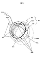
さらに、本実施の形態では、ステータコア941の外周に接触するように、ステータコア軸方向に延在する複数の導体バー950bと、外周面を一周して各導体バー950bの一端を連結する導体リング950cとが設けられている。図5は、導体リング950cおよび導体バー950bが設けられたステータ940の斜視図である。ステータコア941には3相分の電機子巻線945が設けられている。ステータ940の軸方向端部には、ハウジング912に設けられた交流端子902U〜902W(図4参照)と接続されるコイル端子903U〜903Wが引き出されている。
Furthermore, in the present embodiment, a plurality of conductor bars 950b extending in the stator core axial direction so as to contact the outer periphery of the
複数の導体バー950bは、ステータコア941の一周に亘って所定の間隔で配置されている。図4に示す構造の回転電機900の場合、ステータコア941はセンターハウジング909の内周面に焼き嵌めされている。各導体バー950bは、ステータコア941の焼き嵌めされる面に接触するように固定されている。ステータコア941は、型で打ち抜いた電磁鋼板を複数積層して形成される。そのため、各電磁鋼板との接触を良好とするために、各導体バー950bは、溶接等によりステータコア外周面に固着される。
The plurality of conductor bars 950b are arranged at a predetermined interval over one circumference of the
後述するように、導体バー950bはステータに流れ込んだコモンモード電流(コモンモードノイズ)を集電するために設けられたものであり、導体バー950bの数は一つでも良いが、数が多いほど集電効果が向上する。導体バー950bに流れ込んだコモンモード電流は、導体リング950cに流れ込んだ後に、接続配線700によってインバータ回路の入力側の仮想中性点510Gに戻される。なお、仮想中性点510Gは仮想接地点とも呼ばれる。
As will be described later, the
接続配線700は、ハウジング912とケース12とが対向する部分を貫通するようにケース12内に引き込まれており、電動駆動装置1の筐体外に引き出されることはない。この対向する部分においては、ケース12の底面部に貫通穴が形成され、交流端子902U〜902Wがケース12内に突出している。
The
なお、上述のように、一つの接続配線700を回転電機側から電力変換装置側まで引き回す構造でなくても良い。例えば、電機子巻線945と交流バスバー802U〜802Wとの接続のために交流端子902U〜902Wをハウジング912に設けたように、ハウジング912にハウジング内からケース12内に貫通する端子部を設け、その端子部を介して回転電機側の接続配線と電力変換装置側の接続配線とを接続するようにしても良い。
Note that, as described above, one
本実施の形態では、コモンモード電流を集電する部材として導体バー950bおよび導体リング950cをステータコア941の外周面に固着させたが、集電体としての機能を有するものであればどのような構造であっても構わない。例えば、ステータコア941の外周面全体に厚膜メッキを施し、そのメッキ部に接続配線700を接続するようにしても良い。また、ステータコア941を構成する電磁鋼板の一部を導体板で置き換えるなどして、ステータコア941の一部に集電体の機能を付加するようにしても良い。集電体に用いられる材料としては、例えば、アルミや銅が用いられる。
In the present embodiment, the
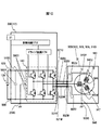
図6は電力変換装置200の内部を詳細に示す図であり、図2に示した電力変換装置200からケース12を削除して示した場合の外観斜視図である。また、図7〜9は電力変換装置200の回路構成を説明するブロック図である。
FIG. 6 is a diagram showing in detail the inside of the
まず、図7〜9を用いて、電力変換装置200の回路構成について説明する。図2に示したケース12、ハウジング912、フロントブラケット908およびリヤブラケット910や図4に示したセンターブラケット909は、金属材料であるアルミダイカスト等で形成される。そして、図7に示すように、ハウジング912およびケース12が車両のボディにボルト等で固定され、それらは車両側のシャシグランド200G,900Gと電気的に接続されている。なお、図8は図7と同じ回路を示したものであるが、ステータ940の部分を回路記号ではなく図5に示したステータ940で記載したものである。
First, the circuit configuration of the
図7に示すように、インバータ回路140は、バッテリ136と直流コネクタ(不図示)を介して電気的に接続されており、バッテリ136とインバータ回路140との相互において電力の授受が行われる。回転電機900をモータとして動作させる場合には、インバータ回路140はバッテリ136から供給された直流電力に基づき交流電力を発生し、交流端子320U〜320Wを介して回転電機900に供給する。電力変換装置200の交流端子320U〜320Wは、金属製の交流バスバー802U〜802Wを介して回転電機900の交流端子902U〜902Wに接続される。
As shown in FIG. 7, the
なお、本実施形態では、バッテリ136の電力によって回転電機900をモータとして作動させることにより、回転電機900の動力のみで車両の走行駆動を行うことができる。さらに、本実施形態では、エンジン120の動力或いは車輪からの動力によって回転電機900を発電機として作動させることにより、バッテリ136の充電を行うことができる。
Note that in this embodiment, the rotating
また、図1では省略したが、バッテリ136は、さらに補機用のモータを駆動するための電源としても使用される。補機用のモータとしては、例えば、エアコンディショナーのコンプレッサを駆動するモータ、あるいは制御用の油圧ポンプを駆動するモータなどがある。補機用パワーモジュールは、バッテリ136から直流電力が供給され、交流電力を発生して補機用のモータに供給する。補機用パワーモジュールはインバータ回路140と基本的には同様の回路構成および機能を持ち、補機用のモータに供給する交流の位相や周波数、電力を制御する。なお、電力変換装置200は、インバータ回路140に供給される直流電力を平滑化するためのコンデンサ500Xを備えている。
Although omitted in FIG. 1, the
電力変換装置200は通信用のコネクタ21を備えており、このコネクタ21により上位の制御装置から指令を受けたりあるいは上位の制御装置に状態を表すデータを送信したりする。電力変換装置200の制御回路172は、コネクタ21から入力される指令に基づいて回転電機900の制御量を演算し、回転電機900をモータとして運転するか発電機として運転するかを演算し、さらに、その演算結果に基づいて制御パルスを発生してドライバ回路174へ供給する。ドライバ回路174は、供給された制御パルスに基づいて、インバータ回路140を制御するための駆動パルスを発生する。
The
図9はインバータ回路140の構成を説明する図である。なお、以下で半導体スイッチング素子として絶縁ゲート型バイポーラトランジスタを使用しており、以下略してIGBTと記す。スイッチング用パワー半導体素子としては金属酸化物半導体型電界効果トランジスタ(以下略してMOSFETと記す)を用いてもよい、この場合はダイオード156やダイオード166は不要となる。スイッチング用パワー半導体素子としては、IGBTは直流電圧が比較的高い場合に適していて、MOSFETは直流電圧が比較的低い場合に適している。
FIG. 9 is a diagram illustrating the configuration of the
上アームとして動作するIGBT328U〜328W及びダイオード156U〜156Wと、下アームとして動作するIGBT330U〜330W及びダイオード166U〜166Wとで、上下アームの直列回路150U〜150Wが構成される。インバータ回路140は、この直列回路150を、出力しようとする交流電力のU相、V相、W相の3相に対応して備えている。
これらの3相は、本実施の形態では回転電機900の3相電機子巻線の各相巻線に対応している。3相の上下アームの直列回路150は、直列回路の中点部分である中間電極169から交流電流を出力する。この中間電極169は、交流端子320U〜320Wを通して回転電機900の交流端子902U〜902Wに接続される。上述したように、交流端子320U〜320Wと交流端子902U〜902Wとは交流バスバー802U〜802Wによって接続される。
These three phases correspond to each phase winding of the three-phase armature winding of the rotating
上アームのIGBT328のコレクタ電極153は、正極端子157を介してYコンデンサを構成するコンデンサ500Yおよび平滑用のコンデンサ500Xの正極側コンデンサ端子506Y,506Xに電気的に接続されている。また、下アームのIGBT330のエミッタ電極154は、負極端子158を介してコンデンサ500Yとコンデンサ500Xの負極側コンデンサ端子504Y,504Xに電気的に接続されている。一端が導体リング950c(図7,8参照)に接続された接続配線700は、コンデンサ510Yaを介して2つのコンデンサ500Yの中間点である仮想中性点510Gに接続される。
The
コンデンサ500Xは、正極側のコンデンサ端子506Xおよび負極側のコンデンサ端子504Yと、正極側の電源端子509および負極側の電源端子508とを備えている。バッテリ136からの高電圧の直流電力は、正極側の電源端子509および負極側の電源端子508に供給され、コンデンサ500Xの正極側のコンデンサ端子506および負極側のコンデンサ端子504からインバータ回路140へ供給される。
The
一方、交流電力からインバータ回路140によって変換された直流電力は、正極側のコンデンサ端子506Xおよび負極側のコンデンサ端子504Yからコンデンサ500Xに供給され、さらに、正極側の電源端子509および負極側の電源端子508から直流コネクタ(不図示)を介してバッテリ136に供給され、バッテリ136に蓄積される。
On the other hand, the DC power converted from the AC power by the
制御回路172は、IGBT328,330のスイッチングタイミングを演算処理するためのマイクロコンピュータ(以下、「マイコン」と記述する)を備えている。マイコンへの入力情報としては、回転電機900に対して要求される目標トルク値、直列回路150から回転電機900に供給される電流値、及び回転電機900の回転子の磁極位置がある。
The control circuit 172 includes a microcomputer (hereinafter referred to as “microcomputer”) for calculating the switching timing of the IGBTs 328 and 330. Information input to the microcomputer includes a target torque value required for the rotating
目標トルク値は、不図示の上位の制御装置から出力された指令信号に基づくものである。電流値は、電力変換装置200に設けられた電流センサ(不図示)による検出信号に基づいて検出されたものである。磁極位置は、回転電機900に設けられたレゾルバなどの回転磁極センサ(不図示)から出力された検出信号に基づいて検出されたものである。
The target torque value is based on a command signal output from a host controller (not shown). The current value is detected based on a detection signal from a current sensor (not shown) provided in the
制御回路172内のマイコンは、目標トルク値に基づいて回転電機900のd軸,q軸の電流指令値を演算し、この演算されたd軸,q軸の電流指令値と、検出されたd軸,q軸の電流値との差分に基づいてd軸,q軸の電圧指令値を演算し、この演算されたd軸,q軸の電圧指令値を、検出された磁極位置に基づいてU相、V相、W相の電圧指令値に変換する。そして、マイコンは、U相、V相、W相の電圧指令値に基づく基本波(正弦波)と搬送波(三角波)との比較に基づいてパルス状の変調波を生成し(以下PWM制御)、この生成された変調波をPWM(パルス幅変調)信号としてドライバ回路174に出力する。
The microcomputer in the control circuit 172 calculates the d-axis and q-axis current command values of the rotating
ドライバ回路174は、上記制御パルスに基づき、各相の直列回路150の上アームあるいは下アームを構成するIGBT328やIGBT330を制御するための駆動パルスを各相のIGBT328やIGBT330に供給する。下アームを駆動する場合、ドライバ回路174は、PWM信号を増幅したドライブ信号を対応する下アームのIGBT330のゲート電極に出力する。また、上アームを駆動する場合には、ドライバ回路174は、PWM信号の基準電位のレベルを上アームの基準電位のレベルにシフトしてからPWM信号を増幅し、これをドライブ信号として対応する上アームのIGBT328のゲート電極に出力する。IGBT328やIGBT330は、ドライバ回路174からの駆動パルスに基づき、導通あるいは遮断動作を行い、バッテリ136から供給された直流電力を三相交流電力に変換し、この変換された電力は回転電機900に供給される。
Based on the control pulse, the driver circuit 174 supplies a drive pulse for controlling the IGBT 328 and IGBT 330 constituting the upper arm or the lower arm of each
ところで、電力変換装置200と回転電機900とが別体とされている従来の電動駆動装置では、回転電機900の交流端子321U〜321Wは、通常、図10に示すようにシールドケーブル820U〜820Wを介して回転電機900の交流端子902U〜902Wに接続されている。一般的に、直列回路150の交流出力端子と電力変換装置200の交流端子321U〜321Wとの間は金属のバスバーで接続されており、この交流端子320U〜320Wにシールドケーブル820U〜820Wが接続される。
By the way, in the conventional electric drive device in which the
一方、本実施形態の電動駆動装置では、図2に示すように電力変換装置200と回転電機900とを一体としている。そのため、図6に示すように直列回路150の交流端子320U〜320Wに接続された交流バスバー802U〜802Wの端部を、回転電機900の交流端子902U〜902Wに直接接続するようにしている。すなわち、シールドケーブル820U〜820Wが省略される。インバータ回路140の上方には、ドライバ回路174が搭載されたドライバ回路基板22および制御回路172が搭載された制御回路基板20が、順に配置されている。
On the other hand, in the electric drive device of the present embodiment, the
電力変換装置200のケース12の側面には冷却水の入口配管13と出口配管14が設けられており、冷却水が電力変換装置200内に設けられた冷却水路(不図示)を通ることで、3相インバータ回路140及び周辺部品が冷却される。
A cooling
次に、本実施の形態の特徴である、図5に示した導体バー950b、導体リング950cおよび接続配線700の機能について説明する。まず、図10〜12を参照して、従来の電動駆動装置におけるコモンモードノイズ(コモンモード電流とも呼ばれる)について説明する。3相電機子巻線945の各相巻線945U〜945Wの相電圧をそれぞれVu、Vv、Vwとしたとき、中性点946の電位V0は、次式(1)で表される。
V0=(Vu+Vv+Vw)/3 ・・・(1)
Next, functions of the
V0 = (Vu + Vv + Vw) / 3 (1)
バッテリ136の電圧をVdcとし、直流母線P、N(図9参照)の中間電位を仮想中性点として零とすれば、P電位はVdc/2、N電位は−Vdc/2となる。2つのコンデンサ500Yの中間510Gはこの仮想中性点となっている。
If the voltage of the
UVW各相の相電圧は、インバータ回路140の上アームのIGBT328U〜328W,下アームのIGBT330U〜330WのON、OFFにより以下のように変化する。
U相:(328U、330U)=(ON、OFF)=Vdc/2
U相:(328U、330U)=(OFF、ON)=−Vdc/2
V相:(328V、330V)=(ON、OFF)=Vdc/2
V相:(328V、330V)=(OFF、ON)=−Vdc/2
W相:(328W、330W)=(ON、OFF)=Vdc/2
W相:(328W、330W)=(OFF、ON)=−Vdc/2
The phase voltage of each phase of the UVW changes as follows depending on ON / OFF of the
U phase: (328U, 330U) = (ON, OFF) = Vdc / 2
U phase: (328U, 330U) = (OFF, ON) = − Vdc / 2
V phase: (328V, 330V) = (ON, OFF) = Vdc / 2
V phase: (328V, 330V) = (OFF, ON) = − Vdc / 2
W phase: (328 W, 330 W) = (ON, OFF) = Vdc / 2
W phase: (328 W, 330 W) = (OFF, ON) = − Vdc / 2
上述したようにPWM制御を行った場合、インバータ回路140の上アームのIGBT328U〜328W,下アームのIGBT330U〜330Wのスイッチングパターンは以下の8つのモードである。なお、ここでは、上アームONで下アームOFFの場合を1、上アームOFFで下アームONの場合を0と表している。
モード0:(U、V、W)=(000)
モード1:(U、V、W)=(100)
モード2:(U、V、W)=(110)
モード3:(U、V、W)=(010)
モード4:(U、V、W)=(011)
モード5:(U、V、W)=(001)
モード6:(U、V、W)=(101)
モード7:(U、V、W)=(111)
When PWM control is performed as described above, the switching patterns of the
Mode 0: (U, V, W) = (000)
Mode 1: (U, V, W) = (100)
Mode 2: (U, V, W) = (110)
Mode 3: (U, V, W) = (010)
Mode 4: (U, V, W) = (011)
Mode 5: (U, V, W) = (001)
Mode 6: (U, V, W) = (101)
Mode 7: (U, V, W) = (111)
上記各モード0〜モード7における中性点電位V0を、式(1)を使って計算すると、それぞれ以下のようになる。
モード0:V0=(−Vdc/2−Vdc/2−Vdc/2)/3=−Vdc/2
モード1:V0=(Vdc/2−Vdc/2−Vdc/2)/3=−Vdc/6
モード2:V0=(Vdc/2+Vdc/2−Vdc/2)/3=Vdc/6
モード3:V0=(−Vdc/2+Vdc/2−Vdc/2)/3=−Vdc/6
モード4:V0=(−Vdc/2+Vdc/2+Vdc/2)/3=Vdc/6
モード5:V0=(−Vdc/2−Vdc/2+Vdc/2)/3=−Vdc/6
モード6:V0=(Vdc/2−Vdc/2+Vdc/2)/3=Vdc/6
モード7:V0=(Vdc/2+Vdc/2+Vdc/2)/3=Vdc/2
When the neutral point potential V0 in each of the above modes 0 to 7 is calculated using the equation (1), it is as follows.
Mode 0: V0 = (− Vdc / 2−Vdc / 2−Vdc / 2) / 3 = −Vdc / 2
Mode 1: V0 = (Vdc / 2-Vdc / 2-Vdc / 2) / 3 = -Vdc / 6
Mode 2: V0 = (Vdc / 2 + Vdc / 2-Vdc / 2) / 3 = Vdc / 6
Mode 3: V0 = (-Vdc / 2 + Vdc / 2-Vdc / 2) / 3 = -Vdc / 6
Mode 4: V0 = (-Vdc / 2 + Vdc / 2 + Vdc / 2) / 3 = Vdc / 6
Mode 5: V0 = (-Vdc / 2-Vdc / 2 + Vdc / 2) / 3 = -Vdc / 6
Mode 6: V0 = (Vdc / 2−Vdc / 2 + Vdc / 2) / 3 = Vdc / 6
Mode 7: V0 = (Vdc / 2 + Vdc / 2 + Vdc / 2) / 3 = Vdc / 2
通常、PWM制御では、上下アームのスイッチング毎にモードは「7→6→1→0→1→6→7→6→1→0→1→2→7→2→1→0→1→2→7・・・・」のように繰り返される。そうすると、中性点電圧は「Vdc/2→Vdc/6→―Vdc/6→−Vdc/2→−Vdc/6→Vdc/6→・・・・」のようにVdc/3の電位変化を繰り返す。 Normally, in PWM control, the mode is “7 → 6 → 1 → 0 → 1 → 6 → 7 → 6 → 1 → 0 → 1 → 2 → 7 → 2 → 1 → 0 → 1 → 2” every time the upper and lower arms are switched. → 7 ... "and so on. Then, the neutral point voltage changes the potential of Vdc / 3 as follows: “Vdc / 2 → Vdc / 6 → −Vdc / 6 → −Vdc / 2 → −Vdc / 6 → Vdc / 6 →. repeat.
上述したように中性点946の電位が変動すると、浮遊容量947(巻線−ステータコア間の浮遊容量)は充放電を繰り返すことになる。そのため、ステータコア945からステータ945に金属接触しているセンターブラケット909へコモンモード電流が流れ、さらにはハウジング912、フロントブラケット908、リヤブラケット910へとコモンモード電流が流れる。
As described above, when the potential at the
なお、ステータコア941とハウジング912、フロントブラケット908およびリヤブラケット910との間の浮遊容量948は、浮遊容量947に比べて小さいが、ステータコア941、センターハウジング909、ハウジング912、フロントブラケット908、リヤブラケット910の固定方法が焼き嵌めやボルト締結といった面接触であることから設けたものである。
The
ところで、図10に示すように電力変換装置200と回転電機900とが別体である場合には、上述した特許文献1に記載の発明のようにコモンモード電流を低減するために特別なノイズ低減回路を追加する代わりに、図10のような構成とすることで、コモンモード電流対策をすることが可能である。図10に示すように、電力変換装置200の交流端子321U〜321Wと回転電機900の交流端子902U〜902Wとをシールドケーブル820U〜820Wで接続することで、コモンモード電流がシャシグランド900Gから車両側を経由してシャシグランド200Gに環流するのを容易に防止することができる。
By the way, when the
図11は、図10のシールドケーブル820U〜820Wの部分を拡大して示した模式図である。図10において、シールドケーブル820Uのシールド820USは、一端が接続部材820Uaによって電力変換装置200のケース12に接続され、他端が接続部材820Ubによって回転電機900のハウジング912に接続されている。同様に、シールドケーブル820Vのシールド820VSは、一端が接続部材820Vaによってケース12に接続され、他端が接続部材820Vbによってハウジング912に接続されている。同様に、シールドケーブル820Wのシールド820WSは、一端が接続部材820Waによってケース12に接続され、他端が接続部材820Wbによってハウジング912に接続されている。
FIG. 11 is an enlarged schematic view showing the
インバータ回路140に設けられたスイッチング素子328U〜328W,330U〜330Wのスイッチングに伴うコモンモード電流は、図12の破線で示すように、中性点946、ステータコア941、ハウジング912、シールド802US〜802WS、ケース12と流れ、電力変換装置200のコンデンサ500Yの仮想中性点510Gへ戻る。このように、従来の装置では、コモンモード電流がハウジング912→シールド802US〜802WS→ケース12→仮想中性点510Gと流れるように構成することで、シャシグランド900Gとシャシグランド200Gとの間を還流するコモンモードノイズ(コモンモード電流)を低減することができる。なお、仮想中性点510Gは電力変換装置200のシャシグランド200Gに接続されている。
The common mode current accompanying switching of the
しかしながら、本実施形態の機電一体型の電動駆動装置1では、図6に示すように電力変換装置200に設けられた交流バスバー802U〜802Wを回転電機900の交流端子902U〜902Wと直接接続しているため、図10〜12に示したようなシールドケーブル820U〜820Wを用いた対策を適用することができない。
However, in the electromechanical integrated
例えば、図13のように、図10のシールドケーブル820U〜820Wを単純に交流バスバー802U〜802Wで置き換えた構造の場合には、コモンモード電流は、破線で示すように回転電機側のシャシグランド900Gから車両側を流れて回転電機側のシャシグランド200Gへと流れ込むことになる。そのため、このコモンモード電流(コモンモードノイズ)が、車両側の制御装置(前述した上位制御装置)や電力変換装置200の制御回路172に対して悪影響を及ぼすことになる。通常、弱電系の制御回路172はシャシグランド200Gとは別系統でグランドがとられているが、そのグランドから制御回路172にコモンモード電流が流れ込むことになる。
For example, as shown in FIG. 13, when the shielded
一方、本実施の形態では、図14に示すようにステータコア941の外周面に導体バー950bおよび導体リング950cを設け、導体リング950cを接続配線700によって電力変換装置200の仮想中性点510Gに接続している。また、接続配線700は、図7に示したように回転電機900および電力変換装置200の筐体内を通っている。
On the other hand, in this embodiment, as shown in FIG. 14,
導体バー950bはステータコア941と電気的に導通するように設けられているので、導体バー950bの導通抵抗を充分小さくしておけば、ステータコア941に流れ込んだコモンモード電流は、図14の矢印で示すように、ステータコア941とセンターブラケット909の焼き嵌め面ではなく導体バー950bおよび導体リング950cへと流れ込む。
Since the
導体バー950bおよび導体リング950cへ流れ込んだコモンモード電流は、図15に示すように、接続配線700によって回転電機900側から電力変換装置200側へ導かれ、コンデンサ510Yaを介して仮想中性点510Gに流れ込む。なお、本実施の形態の場合、仮想中性点510Gはシャシグランド200Gに接続されていない。なお、コンデンサ510Yaを介して接続配線700を仮想中性点510Gに接続しているが、発生するノイズのレベルに応じて設けても良いし省略しても良い。ノイズレベルが高い場合には、コンデンサ510Yaを設けるのが好ましい。
As shown in FIG. 15, the common mode current that has flowed into the
上述した実施の形態では、ステータコア941をセンターブラケット909の内周面に焼き嵌めし、そのセンターブラケット909をハウジング912に固定する構成とされているが、本発明はこのような構造のステータ940に限定されるものではない。図17,18はステータ940の他の構造の一例を示したものである。図17は斜視図であり、図18はロータ軸に垂直な断面を示したものである。
In the embodiment described above, the
ステータ942は、ステータコア943と3相電機子巻線945を有する。ステータコア943の外周には、ボルト用の貫通穴が形成された固定部943Xが複数設けられている。センターブラケット909Xの内周部に収納されたステータコア943は、ボルト960によってセンターブラケット909Xに締結されている。
ステータコア943の軸方向に伸びる導体バー950bは、ステータコア943の外周面に少なくとも一つ設けられ、ステータコア943と電気的に導通している。各導体バー950bは、ステータコア943の軸方向端部近傍に設けられた導体リング950cに電気的に接続されている。導体リング950cには接続配線700が接続されている。このように、コモンモード電流に対する集電構造に関しては、上述した実施の形態と同構造を有している。
At least one
このような構造の場合、ステータコア943とセンターブラケット909Xとの間に隙間が形成され、ステータコア943からセンターブラケット909X側へ流れるコモンモード電流を低減できる。そのため、導体バー950bおよび導体リング950cによるコモンモード電流の集電を、より効率的に行うことができる。
In such a structure, a gap is formed between the
図18は機電一体型電動駆動装置の別の実施形態を示す図である。本実施の形態では、回転電機900のハウジング912には、ステータ940が収納される第1のハウジング部912aと、電力変換装置200が収納される第2のハウジング部912bとが一体に形成されている。この場合、電力変換装置200のケース12は省略され、ケース12内の構成部品はハウジング部912b内に直接配置される。
FIG. 18 is a diagram showing another embodiment of the electromechanical integrated electric drive device. In the present embodiment, the
このような構造とすることにより、図2に示すような電力変換装置200のケース12と回転電機900のハウジング912との固定部(継ぎ目)がなくなり、よりコモンモード電流を電動駆動装置1の筐体内に封じ込めやすくなる。そのため、放射ノイズを低減することが出来るという効果がある。また、電力変換装置200のケース12が省略できるため、図2の構造に比べてコスト低減を図ることができる。
With such a structure, there is no fixed portion (seam) between the
(a)以上説明したように、電動駆動装置1は、ロータ930、電機子巻線945が装着されたステータコア941を有するステータ940、および、電機子巻線945の交流端子902U〜902Wが配置されステータ940を保持するハウジング912が設けられた回転電機900と、インバータ回路140および該インバータ回路140と交流端子902U〜902Wとを接続する交流バスバー802U〜802Wを有し、ハウジング912の外周に固定される電力変換装置200と、を備える。そして、ステータコア941の外周面に接触して設けられ、ステータ940の浮遊容量に起因するコモンモード電流を集電する集電体である導体バー950bおよび導体リング950cと、インバータ回路140の直流入力側の仮想中性点510Gと導体リング950cとを接続する接続配線700と、を備えるようにした。
(A) As described above, the
そのため、コモンモード電流は、図15に示すように導体バー950bに流れ込み、導体リング950cおよび接続配線700を介して、インバータ回路140の直流入力側の仮想中性点510Gに流れ込む。その結果、制御回路172や車両側の制御装置にコモンモード電流が流れ込むのを防止することができる。このように、本実施の形態では、特許文献1に記載のような特別なノイズ低減回路を設けなくとも、上述したような簡単な構成でコモンモードノイズ低減を図ることができる。
Therefore, the common mode current flows into the
(b)また、電力変換装置200の金属製ケース12を回転電機900のハウジング912に固定する構造において、導体リング950cに接続された接続配線700は、ハウジング912とケース12とが相対する固定面(図4に示すハウジング912の面912eやケース12の底面)を貫通するようにハウジング912の内部からケース12の内部に引き込まれるようにするのが、コモンモード電流の他の機器への影響を防止する点で好ましい。
(B) In the structure in which the
(c)さらに、ハウジング912を、ステータコア941を収納する第1のハウジング部912aと、第1のハウジング部912aと一体に形成され電力変換装置200を収納する第2のハウジング部912bとを備える構成とするのが好ましい。このような構成とすることにより、電力変換部200の筐体と回転電機の筐体との間に継ぎ目が無い構造となり、コモンモード電流を金属製の筐体内に封じ込めやすくなり、放射ノイズを低減することができる。
(C) Further, the
上述した各実施形態はそれぞれ単独に、あるいは組み合わせて用いても良い。それぞれの実施形態での効果を単独あるいは相乗して奏することができるからである。また、本発明の特徴を損なわない限り、本発明は上記実施の形態に何ら限定されるものではない。 Each of the embodiments described above may be used alone or in combination. This is because the effects of the respective embodiments can be achieved independently or synergistically. In addition, the present invention is not limited to the above embodiment as long as the characteristics of the present invention are not impaired.
1:電動駆動装置、12:ケース、20:制御回路基板、22:ドライバ回路基板、140:インバータ回路、172:制御回路、174:ドライバ回路、200:電力変換装置、200G,900G:シャシグランド、320U〜320W,321U〜321W,902U〜902W:交流端子、500X,500Y,500Ya:コンデンサ、510G,946:仮想中性点、700:接続配線、802U〜802W:交流バスバー、900:回転電機、909:センターブラケット、912:ハウジング、912a:第1のハウジング部、912b:第2のハウジング部、930:ロータ、940,942:ステータ、941,943:ステータコア、943X:固定部、945:電機子巻線、950b:導体バー、950c:導体リング 1: electric drive device, 12: case, 20: control circuit board, 22: driver circuit board, 140: inverter circuit, 172: control circuit, 174: driver circuit, 200: power converter, 200G, 900G: chassis ground, 320U to 320W, 321U to 321W, 902U to 902W: AC terminal, 500X, 500Y, 500Ya: capacitor, 510G, 946: virtual neutral point, 700: connection wiring, 802U to 802W: AC bus bar, 900: rotating electric machine, 909 : Center bracket, 912: Housing, 912a: First housing part, 912b: Second housing part, 930: Rotor, 940, 942: Stator, 941, 943: Stator core, 943X: Fixed part, 945: Armature winding Line, 950b: Conductor bar, 950c: Conductor line Grayed
Claims (6)
インバータ回路および該インバータ回路と前記交流端子とを接続する交流バスバーを有し、前記ハウジングの外周に固定される電力変換装置と、を備えた機電一体型の電動駆動装置であって、
前記ステータコアに接触して設けられ、前記ステータの浮遊容量に起因するコモンモード電流を集電する集電体と、
前記インバータ回路の直流入力側の仮想中性点と前記集電体とを接続する接続配線と、を備えたことを特徴とする機電一体型の電動駆動装置。 A rotor, a stator having a stator core on which an armature winding is mounted, and a rotating electric machine provided with a housing in which an AC terminal of the armature winding is arranged and holds the stator;
A power conversion device having an inverter circuit and an AC bus bar connecting the inverter circuit and the AC terminal, and being fixed to the outer periphery of the housing, is an electromechanically integrated electric drive device comprising:
A current collector that is provided in contact with the stator core and collects a common mode current caused by stray capacitance of the stator;
An electromechanically integrated electric drive device comprising: a connection neutral line connecting a virtual neutral point on the DC input side of the inverter circuit and the current collector.
前記電力変換装置は、前記インバータ回路および前記交流バスバーを収納すると共に前記ハウジングの外周に固定される金属筐体を備え、
一端が前記集電体に接続された前記接続配線は、前記ハウジングと前記金属筐体とが相対する固定面を貫通するように前記ハウジングの内部から前記金属筐体の内部に引き込まれて、前記仮想中性点に接続されることを特徴とする機電一体型の電動駆動装置。 In the electromechanical integrated electric drive device according to claim 1,
The power converter includes a metal housing that houses the inverter circuit and the AC bus bar and is fixed to an outer periphery of the housing.
The connection wiring, one end of which is connected to the current collector, is drawn from the inside of the housing to the inside of the metal casing so that the housing and the metal casing are opposed to each other, An electromechanically integrated electric drive device characterized by being connected to a virtual neutral point.
前記ハウジングは、前記ステータコアを収納する第1のハウジング部と、該第1のハウジング部と一体に形成され前記電力変換装置を収納する第2のハウジング部と、を備えたことを特徴とする機電一体型の電動駆動装置。 In the electromechanical integrated electric drive device according to claim 1,
The housing includes a first housing portion that houses the stator core, and a second housing portion that is formed integrally with the first housing portion and houses the power converter. Integrated electric drive device.
前記接続配線は、コンデンサを介して前記仮想中性点に接続されることを特徴とする機電一体型の電動駆動装置。 In the electromechanically integrated electric drive device according to any one of claims 1 to 3,
The electromechanical integrated electric drive device, wherein the connection wiring is connected to the virtual neutral point via a capacitor.
前記集電体は、回転電機軸方向に沿って延在するように前記ステータコアの外周面に固着された少なくとも一つの導体バーと、前記導体バーの端部に接続され、前記ステータコアの外周面を周回する導体リングと、を備え、
前記接続配線は前記導体リングに接続されていることを特徴とする機電一体型の電動駆動装置。 The electromechanical integrated electric drive device according to any one of claims 1 to 4,
The current collector is connected to at least one conductor bar fixed to the outer peripheral surface of the stator core so as to extend along the axial direction of the rotating electrical machine, and to an end of the conductor bar, and the outer peripheral surface of the stator core is A conductor ring that circulates, and
The electromechanical integrated electric drive device, wherein the connection wiring is connected to the conductor ring.
前記ステータコアは、前記ハウジングに締結するための締結部をコア外周に有し、
前記締結部を前記ハウジングに締結することで、前記ステータが前記ハウジングにより保持されることを特徴とする機電一体型の電動駆動装置。 In the electromechanical integrated electric drive device according to any one of claims 1 to 5,
The stator core has a fastening portion on the outer periphery of the core for fastening to the housing,
An electromechanically integrated electric drive device characterized in that the stator is held by the housing by fastening the fastening portion to the housing.
Priority Applications (3)
| Application Number | Priority Date | Filing Date | Title |
|---|---|---|---|
| JP2011259229A JP2013115904A (en) | 2011-11-28 | 2011-11-28 | Combined mechano-electric electric driving apparatus |
| US14/360,788 US20140306563A1 (en) | 2011-11-28 | 2012-11-05 | Mechanical-Electrical Integrated Electric Drive System |
| PCT/JP2012/078562 WO2013080748A1 (en) | 2011-11-28 | 2012-11-05 | Electromechanical electric drive device |
Applications Claiming Priority (1)
| Application Number | Priority Date | Filing Date | Title |
|---|---|---|---|
| JP2011259229A JP2013115904A (en) | 2011-11-28 | 2011-11-28 | Combined mechano-electric electric driving apparatus |
Publications (2)
| Publication Number | Publication Date |
|---|---|
| JP2013115904A true JP2013115904A (en) | 2013-06-10 |
| JP2013115904A5 JP2013115904A5 (en) | 2014-03-13 |
Family
ID=48535216
Family Applications (1)
| Application Number | Title | Priority Date | Filing Date |
|---|---|---|---|
| JP2011259229A Pending JP2013115904A (en) | 2011-11-28 | 2011-11-28 | Combined mechano-electric electric driving apparatus |
Country Status (3)
| Country | Link |
|---|---|
| US (1) | US20140306563A1 (en) |
| JP (1) | JP2013115904A (en) |
| WO (1) | WO2013080748A1 (en) |
Cited By (10)
| Publication number | Priority date | Publication date | Assignee | Title |
|---|---|---|---|---|
| JP2015053770A (en) * | 2013-09-05 | 2015-03-19 | 株式会社日本自動車部品総合研究所 | Power converter |
| JP2016077117A (en) * | 2014-10-08 | 2016-05-12 | 三菱自動車工業株式会社 | Vehicle motor apparatus |
| JP2017011823A (en) * | 2015-06-18 | 2017-01-12 | 株式会社デンソー | Electric drive unit |
| JP2018034776A (en) * | 2016-08-26 | 2018-03-08 | 株式会社デンソー | In-vehicle apparatus |
| JP2019030183A (en) * | 2017-08-02 | 2019-02-21 | 本田技研工業株式会社 | Noise cancellation system and electric vehicle |
| JP2019149907A (en) * | 2018-02-28 | 2019-09-05 | 株式会社デンソー | Power conversion device |
| WO2022239665A1 (en) * | 2021-05-12 | 2022-11-17 | 株式会社デンソー | Power conversion device |
| WO2024004638A1 (en) * | 2022-06-30 | 2024-01-04 | ニデックインスツルメンツ株式会社 | Motor control unit, motor, and pump device |
| WO2024004637A1 (en) * | 2022-06-30 | 2024-01-04 | ニデックインスツルメンツ株式会社 | Motor control unit, motor, and pump device |
| JP7424790B2 (en) | 2019-10-21 | 2024-01-30 | 本田技研工業株式会社 | vehicle power system |
Families Citing this family (20)
| Publication number | Priority date | Publication date | Assignee | Title |
|---|---|---|---|---|
| EP3074254B1 (en) * | 2013-11-26 | 2019-04-10 | Schaeffler Technologies AG & Co. KG | Hybrid module and power electronics module with a common coolant flow |
| JP6184520B2 (en) * | 2013-12-16 | 2017-08-23 | 三菱電機株式会社 | Mechanical and electric integrated drive device and method for manufacturing the same |
| JP6284271B2 (en) * | 2014-07-14 | 2018-02-28 | アスモ株式会社 | Rotating electric machine |
| FR3029732B1 (en) * | 2014-12-08 | 2018-03-02 | Renault S.A.S | COMPACT ELECTRIC MOTOR POWERTRAIN ARCHITECTURE FOR MOTOR VEHICLE. |
| JP6458483B2 (en) | 2014-12-19 | 2019-01-30 | 株式会社デンソー | Motor control device |
| JP6573456B2 (en) * | 2015-01-28 | 2019-09-11 | 本田技研工業株式会社 | Integrated unit |
| JP6645739B2 (en) * | 2015-01-28 | 2020-02-14 | 本田技研工業株式会社 | Integrated unit |
| US10734890B2 (en) | 2015-05-29 | 2020-08-04 | Nissan Motor Co., Ltd. | Power conversion device |
| WO2017006429A1 (en) * | 2015-07-07 | 2017-01-12 | 日産自動車株式会社 | Arrangement structure for wheel drive device |
| ITUA20162985A1 (en) * | 2016-04-28 | 2017-10-28 | Taco Italia S R L | Circulator for heating and / or cooling systems driven by a permanent magnet synchronous motor with improved electronic control card |
| US10651713B2 (en) * | 2016-07-07 | 2020-05-12 | Arm Ltd. | Grouped tooth electric motor |
| WO2018041913A1 (en) * | 2016-08-31 | 2018-03-08 | Borgwarner Sweden Ab | A hybrid drive module having an electric motor |
| CN212177409U (en) * | 2017-08-31 | 2020-12-18 | 日本电产东测有限公司 | Electric oil pump |
| DE102017216468A1 (en) * | 2017-09-18 | 2019-03-21 | Conti Temic Microelectronic Gmbh | Charging an electrical energy storage of a motor vehicle |
| CN109698517B (en) * | 2017-10-23 | 2023-03-28 | 台达电子企业管理(上海)有限公司 | Method and device for controlling power system |
| JP2019193352A (en) * | 2018-04-19 | 2019-10-31 | スズキ株式会社 | Rotary electric machine |
| TWI661659B (en) * | 2018-06-22 | 2019-06-01 | 群光電能科技股份有限公司 | Integrated motor drive and integrated heat dissipation system |
| FR3094851B1 (en) * | 2019-04-05 | 2021-06-04 | Valeo Siemens Eautomotive France Sas | INVERTER INCLUDING A PART FORMING A DISCHARGE FROM A FIRST PART OF THE UPS |
| WO2022243203A1 (en) * | 2021-05-18 | 2022-11-24 | Magna powertrain gmbh & co kg | Electric drive arrangement for a motor vehicle |
| FR3140829A1 (en) * | 2022-10-14 | 2024-04-19 | Psa Automobiles Sa | GROUNDING ASSEMBLY FOR AN ELECTRIFIED VEHICLE POWER UNIT |
Citations (5)
| Publication number | Priority date | Publication date | Assignee | Title |
|---|---|---|---|---|
| JPH01243843A (en) * | 1988-03-25 | 1989-09-28 | Mitsubishi Electric Corp | Compression cooling device |
| JP2003235269A (en) * | 2002-02-08 | 2003-08-22 | Fuji Electric Co Ltd | Noise reducing apparatus for power converter |
| JP2006311697A (en) * | 2005-04-28 | 2006-11-09 | Hitachi Ltd | Brushless motor system |
| JP2008252962A (en) * | 2007-03-29 | 2008-10-16 | Mitsubishi Heavy Ind Ltd | Integrated electric compressor |
| JP2010233293A (en) * | 2009-03-26 | 2010-10-14 | Honda Motor Co Ltd | Terminal block and inverter case |
Family Cites Families (7)
| Publication number | Priority date | Publication date | Assignee | Title |
|---|---|---|---|---|
| US5821652A (en) * | 1996-08-28 | 1998-10-13 | Marathon Electric Manufacturing Corporation | Dynamoelectric machines with shaft voltage prevention method and structure |
| FI115804B (en) * | 2002-10-21 | 2005-07-15 | Abb Oy | Arrangement to protect the electrical machine against bearing currents |
| US20050285464A1 (en) * | 2004-06-28 | 2005-12-29 | Orders Marcus D | Method and apparatus for dissipating shaft charge |
| AU2007229157B2 (en) * | 2006-03-17 | 2010-01-07 | Vestas Wind Systems A/S | Protection system for an electric generator, wind turbine and use hereof |
| JP4909961B2 (en) * | 2008-09-02 | 2012-04-04 | 日立オートモティブシステムズ株式会社 | Control device for electric power steering |
| JP2009171841A (en) * | 2009-03-16 | 2009-07-30 | Hitachi Ltd | Electric motor system |
| JP5189120B2 (en) * | 2010-03-08 | 2013-04-24 | 日立オートモティブシステムズ株式会社 | Power converter |
-
2011
- 2011-11-28 JP JP2011259229A patent/JP2013115904A/en active Pending
-
2012
- 2012-11-05 US US14/360,788 patent/US20140306563A1/en not_active Abandoned
- 2012-11-05 WO PCT/JP2012/078562 patent/WO2013080748A1/en active Application Filing
Patent Citations (5)
| Publication number | Priority date | Publication date | Assignee | Title |
|---|---|---|---|---|
| JPH01243843A (en) * | 1988-03-25 | 1989-09-28 | Mitsubishi Electric Corp | Compression cooling device |
| JP2003235269A (en) * | 2002-02-08 | 2003-08-22 | Fuji Electric Co Ltd | Noise reducing apparatus for power converter |
| JP2006311697A (en) * | 2005-04-28 | 2006-11-09 | Hitachi Ltd | Brushless motor system |
| JP2008252962A (en) * | 2007-03-29 | 2008-10-16 | Mitsubishi Heavy Ind Ltd | Integrated electric compressor |
| JP2010233293A (en) * | 2009-03-26 | 2010-10-14 | Honda Motor Co Ltd | Terminal block and inverter case |
Cited By (11)
| Publication number | Priority date | Publication date | Assignee | Title |
|---|---|---|---|---|
| JP2015053770A (en) * | 2013-09-05 | 2015-03-19 | 株式会社日本自動車部品総合研究所 | Power converter |
| JP2016077117A (en) * | 2014-10-08 | 2016-05-12 | 三菱自動車工業株式会社 | Vehicle motor apparatus |
| JP2017011823A (en) * | 2015-06-18 | 2017-01-12 | 株式会社デンソー | Electric drive unit |
| JP2018034776A (en) * | 2016-08-26 | 2018-03-08 | 株式会社デンソー | In-vehicle apparatus |
| JP7003449B2 (en) | 2016-08-26 | 2022-01-20 | 株式会社デンソー | In-vehicle device |
| JP2019030183A (en) * | 2017-08-02 | 2019-02-21 | 本田技研工業株式会社 | Noise cancellation system and electric vehicle |
| JP2019149907A (en) * | 2018-02-28 | 2019-09-05 | 株式会社デンソー | Power conversion device |
| JP7424790B2 (en) | 2019-10-21 | 2024-01-30 | 本田技研工業株式会社 | vehicle power system |
| WO2022239665A1 (en) * | 2021-05-12 | 2022-11-17 | 株式会社デンソー | Power conversion device |
| WO2024004638A1 (en) * | 2022-06-30 | 2024-01-04 | ニデックインスツルメンツ株式会社 | Motor control unit, motor, and pump device |
| WO2024004637A1 (en) * | 2022-06-30 | 2024-01-04 | ニデックインスツルメンツ株式会社 | Motor control unit, motor, and pump device |
Also Published As
| Publication number | Publication date |
|---|---|
| US20140306563A1 (en) | 2014-10-16 |
| WO2013080748A1 (en) | 2013-06-06 |
Similar Documents
| Publication | Publication Date | Title |
|---|---|---|
| JP2013115904A (en) | Combined mechano-electric electric driving apparatus | |
| US10797550B2 (en) | Rotary electric machine and vehicle provided with the same | |
| EP2405565B1 (en) | Power converter | |
| JP5851372B2 (en) | Power converter | |
| EP2287032A2 (en) | Power conversion device in a car | |
| WO2013018620A1 (en) | Power conversion apparatus | |
| JP5065986B2 (en) | Semiconductor device driving apparatus and driving method thereof | |
| JP5707279B2 (en) | Power converter | |
| JP2010183750A (en) | Power conversion apparatus | |
| US20140246944A1 (en) | Rotating electrical machine and electric automotive vehicle | |
| JP5802629B2 (en) | Power converter | |
| Brockerhoff et al. | Highly integrated drivetrain solution: Integration of motor, inverter and gearing | |
| WO2013015371A1 (en) | Case division structure of power conversion device | |
| JP2013005067A (en) | Power conversion apparatus | |
| JP2014166043A (en) | Electric power conversion apparatus | |
| JP6243320B2 (en) | Power semiconductor module | |
| JP5380097B2 (en) | Power circuit, power converter | |
| US20220069651A1 (en) | Rotary Electric Machine and Vehicle Provided with the Same | |
| JP2018110497A (en) | Rotary electric machine | |
| JP2014121121A (en) | Power conversion device | |
| WO2022083341A1 (en) | Vehicle electrical system | |
| JP6272064B2 (en) | Power converter | |
| JP6349204B2 (en) | Construction machinery | |
| JP5798951B2 (en) | Inverter device | |
| JP2016086491A (en) | Semiconductor device |
Legal Events
| Date | Code | Title | Description |
|---|---|---|---|
| A521 | Request for written amendment filed |
Free format text: JAPANESE INTERMEDIATE CODE: A523 Effective date: 20140128 |
|
| A621 | Written request for application examination |
Free format text: JAPANESE INTERMEDIATE CODE: A621 Effective date: 20140128 |
|
| A131 | Notification of reasons for refusal |
Free format text: JAPANESE INTERMEDIATE CODE: A131 Effective date: 20140930 |
|
| A521 | Request for written amendment filed |
Free format text: JAPANESE INTERMEDIATE CODE: A523 Effective date: 20141201 |
|
| A02 | Decision of refusal |
Free format text: JAPANESE INTERMEDIATE CODE: A02 Effective date: 20150512 |