JP2013013201A - Electric vehicle - Google Patents

Electric vehicle Download PDF

Info

Publication number
JP2013013201A
JP2013013201A JP2011143335A JP2011143335A JP2013013201A JP 2013013201 A JP2013013201 A JP 2013013201A JP 2011143335 A JP2011143335 A JP 2011143335A JP 2011143335 A JP2011143335 A JP 2011143335A JP 2013013201 A JP2013013201 A JP 2013013201A
Authority
JP
Japan
Prior art keywords
voltage
drive
battery
power line
motor
Prior art date
Legal status (The legal status is an assumption and is not a legal conclusion. Google has not performed a legal analysis and makes no representation as to the accuracy of the status listed.)
Withdrawn
Application number
JP2011143335A
Other languages
Japanese (ja)
Inventor
Shuichi Iwata
秀一 岩田
Current Assignee (The listed assignees may be inaccurate. Google has not performed a legal analysis and makes no representation or warranty as to the accuracy of the list.)
Toyota Motor Corp
Original Assignee
Toyota Motor Corp
Priority date (The priority date is an assumption and is not a legal conclusion. Google has not performed a legal analysis and makes no representation as to the accuracy of the date listed.)
Filing date
Publication date
Application filed by Toyota Motor Corp filed Critical Toyota Motor Corp
Priority to JP2011143335A priority Critical patent/JP2013013201A/en
Publication of JP2013013201A publication Critical patent/JP2013013201A/en
Withdrawn legal-status Critical Current

Links

Images

Classifications

    • YGENERAL TAGGING OF NEW TECHNOLOGICAL DEVELOPMENTS; GENERAL TAGGING OF CROSS-SECTIONAL TECHNOLOGIES SPANNING OVER SEVERAL SECTIONS OF THE IPC; TECHNICAL SUBJECTS COVERED BY FORMER USPC CROSS-REFERENCE ART COLLECTIONS [XRACs] AND DIGESTS
    • Y02TECHNOLOGIES OR APPLICATIONS FOR MITIGATION OR ADAPTATION AGAINST CLIMATE CHANGE
    • Y02TCLIMATE CHANGE MITIGATION TECHNOLOGIES RELATED TO TRANSPORTATION
    • Y02T10/00Road transport of goods or passengers
    • Y02T10/60Other road transportation technologies with climate change mitigation effect
    • Y02T10/62Hybrid vehicles
    • YGENERAL TAGGING OF NEW TECHNOLOGICAL DEVELOPMENTS; GENERAL TAGGING OF CROSS-SECTIONAL TECHNOLOGIES SPANNING OVER SEVERAL SECTIONS OF THE IPC; TECHNICAL SUBJECTS COVERED BY FORMER USPC CROSS-REFERENCE ART COLLECTIONS [XRACs] AND DIGESTS
    • Y02TECHNOLOGIES OR APPLICATIONS FOR MITIGATION OR ADAPTATION AGAINST CLIMATE CHANGE
    • Y02TCLIMATE CHANGE MITIGATION TECHNOLOGIES RELATED TO TRANSPORTATION
    • Y02T10/00Road transport of goods or passengers
    • Y02T10/60Other road transportation technologies with climate change mitigation effect
    • Y02T10/72Electric energy management in electromobility

Abstract

PROBLEM TO BE SOLVED: To enable protecting of an element of a boost converter.SOLUTION: The boost converter is controlled so that the voltage VH of the drive voltage system power line becomes the set target voltage VH*, when the target voltage VH* of the drive voltage system power line set according to the drive of the motor becomes beyond the limits of twice the plus or minus α the voltage VL of the battery voltage system power line when the driving wheel slips (S130, S150). When the target voltage VH* becomes within the range of twice the plus or minus α of the voltage VL, the value exceeding the range of the twice the plus or minus α of the voltage VL is set again as the target voltage VH* and the boost converter is controlled so that the voltage VH of the drive voltage system power line becomes the reset target voltage VH* (S130-S150). As a result, when the driving wheel slips, the excessive grow of the current IL that flows to the reactor of the boost converter can be controlled and the element of the boost converter can be protected more.

Description

本発明は、電動車両に関し、詳しくは、駆動輪に動力を入出力するモータと、バッテリと、リアクトルとスイッチング素子とを有しバッテリが接続された電池電圧系の電力を昇圧してモータが接続された駆動電圧系に供給可能な昇圧コンバータと、駆動電圧系の電圧が車両の運転条件に応じた目標電圧となるよう昇圧コンバータを制御する昇圧制御手段と、を備える電動車両に関する。   The present invention relates to an electric vehicle, and more particularly, a motor connected to a motor by boosting power of a battery voltage system having a motor that inputs / outputs power to / from drive wheels, a battery, a reactor, and a switching element and to which the battery is connected. The present invention relates to an electric vehicle including a boost converter that can be supplied to the drive voltage system and a boost control unit that controls the boost converter so that the voltage of the drive voltage system becomes a target voltage according to the driving conditions of the vehicle.

従来、この種の技術としては、蓄電池と、蓄電池の電圧を昇圧する昇圧回路と、昇圧された直流電圧を交流電圧に変換するインバータと、昇圧された直流電圧の変動を抑制するように昇圧回路を閉ループ制御する電圧制御部と、を備え、電圧制御部の応答時定数を交流電圧の周期の1倍以上としたものが提案されている(例えば、特許文献1参照)。この技術では、閉ループ制御の応答時定数を長くとることによって、交流電圧の周波数変動に対する過度な反応を鈍化させ、蓄電池のリプル電流を低減している。   Conventionally, this type of technology includes a storage battery, a booster circuit that boosts the voltage of the storage battery, an inverter that converts the boosted DC voltage into an AC voltage, and a booster circuit that suppresses fluctuations in the boosted DC voltage. And a voltage control unit that performs closed loop control, and a response time constant of the voltage control unit is set to be equal to or greater than one cycle of the AC voltage (see, for example, Patent Document 1). In this technique, by taking a long response time constant of the closed loop control, an excessive response to the frequency fluctuation of the AC voltage is slowed down, and the ripple current of the storage battery is reduced.

特開2010−148164号公報JP 2010-148164 A

バッテリからの電力を昇圧してモータに供給可能な昇圧コンバータを備える電動車両では、昇圧コンバータの素子の保護を図ることが重要な課題の一つとして考えられている。特に、駆動輪のスリップ時には、モータの回転数の上昇によってモータの消費電力が大きくなりやすく、昇圧コンバータのリアクトルに流れる電流が大きくなりやすいことから、そのピーク値を抑制するために、電流のリプル成分を小さくすることが望まれる。   In an electric vehicle including a boost converter capable of boosting electric power from a battery and supplying it to a motor, it is considered as one of important issues to protect the elements of the boost converter. In particular, when the drive wheel slips, the power consumption of the motor tends to increase due to an increase in the rotation speed of the motor, and the current flowing through the reactor of the boost converter tends to increase. It is desirable to reduce the components.

本発明の電動車両は、昇圧コンバータの素子を保護することを主目的とする。   The main object of the electric vehicle of the present invention is to protect the elements of the boost converter.

本発明の電動車両は、上述の主目的を達成するために以下の手段を採った。   The electric vehicle of the present invention employs the following means in order to achieve the main object described above.

本発明の電動車両は、
駆動輪に動力を入出力するモータと、バッテリと、リアクトルとスイッチング素子とを有し前記バッテリが接続された電池電圧系の電力を昇圧して前記モータが接続された駆動電圧系に供給可能な昇圧コンバータと、前記駆動電圧系の電圧が車両の運転条件に応じた目標電圧となるよう前記昇圧コンバータを制御する昇圧制御手段と、を備える電動車両において、
前記昇圧制御手段は、前記駆動輪のスリップ時には、前記駆動電圧系の電圧が前記電池電圧系の電圧の2倍を含む所定範囲外となるよう前記昇圧コンバータを制御する手段である、
ことを要旨とする。
The electric vehicle of the present invention is
A motor that inputs / outputs power to / from the drive wheels, a battery, a reactor, and a switching element, boosts the power of a battery voltage system to which the battery is connected, and can be supplied to the drive voltage system to which the motor is connected In an electric vehicle comprising: a boost converter; and a boost control means for controlling the boost converter so that the voltage of the drive voltage system becomes a target voltage corresponding to a driving condition of the vehicle.
The step-up control means is means for controlling the step-up converter so that when the drive wheel slips, the voltage of the drive voltage system is outside a predetermined range including twice the voltage of the battery voltage system.
This is the gist.

この本発明の電動車両では、駆動輪のスリップ時には、駆動電圧系の電圧が電池電圧系の電圧の2倍を含む所定範囲外となるよう昇圧コンバータを制御する。リアクトルに流れる電流のリプル成分の大きさΔILは、電池電圧系の電圧をVL,駆動電圧系の電圧をVH,リアクトルのインダクタンスをL,スイッチング素子のスイッチング周波数(キャリア周波数)をfcとすると、次式(1)により計算され、駆動電圧系の電圧VHが電池電圧系の電圧VLの2倍のとき(電池電圧系の電圧VLと駆動電圧系の電圧VHとの比が1:2のとき)に最大となる。前述したように、駆動輪のスリップ時には、リアクトルに流れる電流が大きくなりやすいから、駆動電圧系の電圧が電池電圧系の電圧の2倍を含む所定範囲外となるよう昇圧コンバータを制御することにより、リアクトルに流れる電流のリプル成分が最大とならない範囲で駆動電圧系の電圧を調節することができ、リアクトルに流れる電流のピーク値が過剰になるのを抑制することができる。この結果、昇圧コンバータの素子をより保護することができる。もとより、駆動輪のスリップ時でないときには、駆動電圧系の電圧が電池電圧系の電圧の2倍を含む所定範囲外となるよう昇圧コンバータを制御することを行なわないから、何ら制限されることなく電池電圧系の電力を昇圧して駆動電圧系に供給することができる。   In the electric vehicle of the present invention, when the drive wheel slips, the boost converter is controlled so that the voltage of the drive voltage system is outside a predetermined range including twice the voltage of the battery voltage system. The magnitude ΔIL of the ripple component of the current flowing through the reactor is as follows, assuming that the voltage of the battery voltage system is VL, the voltage of the drive voltage system is VH, the inductance of the reactor is L, and the switching frequency (carrier frequency) of the switching element is fc. When the driving voltage system voltage VH is twice the battery voltage system voltage VL (when the ratio of the battery voltage system voltage VL to the driving voltage system voltage VH is 1: 2). To the maximum. As described above, when the drive wheel slips, the current flowing through the reactor tends to increase. Therefore, by controlling the boost converter so that the voltage of the drive voltage system is outside the predetermined range including twice the voltage of the battery voltage system. The voltage of the drive voltage system can be adjusted in a range where the ripple component of the current flowing through the reactor is not maximized, and the peak value of the current flowing through the reactor can be suppressed from becoming excessive. As a result, the boost converter element can be further protected. Of course, when the driving wheel is not slipping, the boost converter is not controlled so that the voltage of the driving voltage system is out of a predetermined range including twice the voltage of the battery voltage system. The voltage system power can be boosted and supplied to the drive voltage system.

Figure 2013013201
Figure 2013013201

こうした本発明の電動車両において、前記昇圧制御手段は、前記駆動輪のスリップ時に前記駆動電圧系の電圧が前記所定範囲内となるときには、前記駆動電圧系の電圧が前記目標電圧より高く且つ前記所定範囲外となるよう前記昇圧コンバータを制御する手段である、ものとすることもできる。こうすれば、電動機の駆動制御を余裕をもって行なうことができる。   In such an electric vehicle according to the present invention, the boost control means is configured such that when the drive voltage system voltage falls within the predetermined range when the drive wheel slips, the drive voltage system voltage is higher than the target voltage and the predetermined voltage. It may be a means for controlling the boost converter to be out of range. If it carries out like this, drive control of an electric motor can be performed with a margin.

本発明の一実施例としてのハイブリッド自動車20の構成の概略を示す構成図である。1 is a configuration diagram showing an outline of a configuration of a hybrid vehicle 20 as an embodiment of the present invention. モータMG1,MG2を含む電機駆動系の構成の概略を示す構成図である。It is a block diagram which shows the outline of a structure of the electric drive system containing motor MG1, MG2. ハイブリッド用電子制御ユニット70により実行される昇圧制御ルーチンの一例を示すフローチャートである。5 is a flowchart showing an example of a boost control routine executed by a hybrid electronic control unit 70. 電池電圧系電力ライン54bの電圧VLとリプル成分ΔILとの関係を示す説明図である。It is explanatory drawing which shows the relationship between the voltage VL of the battery voltage type | system | group electric power line 54b, and the ripple component (DELTA) IL. 変形例のハイブリッド自動車120の構成の概略を示す構成図である。FIG. 11 is a configuration diagram showing an outline of a configuration of a hybrid vehicle 120 according to a modification. 変形例のハイブリッド自動車220の構成の概略を示す構成図である。FIG. 11 is a configuration diagram showing an outline of a configuration of a hybrid vehicle 220 of a modified example. 変形例のハイブリッド自動車320の構成の概略を示す構成図である。FIG. 11 is a configuration diagram showing an outline of a configuration of a hybrid vehicle 320 of a modified example. 変形例の電機自動車420の構成の概略を示す構成図である。It is a block diagram which shows the outline of a structure of the electric vehicle 420 of a modification.

次に、本発明を実施するための形態を実施例を用いて説明する。   Next, the form for implementing this invention is demonstrated using an Example.

図1は、本発明の一実施例としてのハイブリッド自動車20の構成の概略を示す構成図である。実施例のハイブリッド自動車20は、図示するように、ガソリンや軽油などを燃料とするエンジン22と、エンジン22を駆動制御するエンジン用電子制御ユニット(以下、エンジンECUという)24と、エンジン22のクランクシャフト26にキャリアが接続されると共に駆動輪38a,38bにデファレンシャルギヤ37を介して連結された駆動軸36にリングギヤが接続されたプラネタリギヤ30と、例えば同期発電電動機として構成されて回転子がプラネタリギヤ30のサンギヤに接続されたモータMG1と、例えば同期発電電動機として構成されて回転子が駆動軸36に接続されたモータMG2と、モータMG1,MG2を駆動するためのインバータ41,42と、インバータ41,42をスイッチング制御することによってモータMG1,MG2を駆動制御するモータ用電子制御ユニット(以下、モータECUという)40と、例えばリチウムイオン二次電池として構成されたバッテリ50と、バッテリ50を管理するバッテリ用電子制御ユニット(以下、バッテリECUという)52と、インバータ41,42が接続された電力ライン(以下、駆動電圧系電力ラインという)54aとバッテリ50が接続された電力ライン(以下、電池電圧系電力ラインという)54bとに接続されて駆動電圧系電力ライン54aの電圧VHを電池電圧系電力ライン54bの電圧VLから最大許容電圧VHmaxの範囲内で調節すると共に駆動電圧系電力ライン54aと電池電圧系電力ライン54bとの間で電力のやりとりを行なう昇圧コンバータ55と、車両全体を制御するハイブリッド用電子制御ユニット70と、を備える。ここで、最大許容電圧VHmaxは、後述のコンデンサ57の耐圧よりも若干低い値などを用いることができる。   FIG. 1 is a configuration diagram showing an outline of the configuration of a hybrid vehicle 20 as an embodiment of the present invention. As shown in the figure, the hybrid vehicle 20 of the embodiment includes an engine 22 that uses gasoline or light oil as fuel, an engine electronic control unit (hereinafter referred to as engine ECU) 24 that controls the drive of the engine 22, and a crank of the engine 22. A planetary gear 30 having a carrier connected to the shaft 26 and a ring gear connected to a drive shaft 36 connected to drive wheels 38a and 38b via a differential gear 37, and a rotor configured as a synchronous generator motor, for example. A motor MG1 connected to the sun gear, a motor MG2 configured as a synchronous generator motor and having a rotor connected to the drive shaft 36, inverters 41 and 42 for driving the motors MG1 and MG2, an inverter 41, 42 is controlled by switching control. A motor electronic control unit (hereinafter referred to as a motor ECU) 40 for driving and controlling the motors MG1 and MG2, a battery 50 configured as, for example, a lithium ion secondary battery, and a battery electronic control unit (hereinafter referred to as a battery control unit) that manages the battery 50 Battery ECU) 52, a power line (hereinafter referred to as drive voltage system power line) 54a to which inverters 41 and 42 are connected, and a power line (hereinafter referred to as battery voltage system power line) 54b to which battery 50 is connected. The voltage VH of the drive voltage system power line 54a connected is adjusted within the range of the voltage VL of the battery voltage system power line 54b to the maximum allowable voltage VHmax, and between the drive voltage system power line 54a and the battery voltage system power line 54b. Boost converter 55 for exchanging electric power and high for controlling the entire vehicle It comprises a lid electronic control unit 70. Here, the maximum allowable voltage VHmax may be a value slightly lower than the breakdown voltage of the capacitor 57 described later.

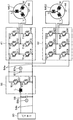
モータMG1およびモータMG2は、いずれも永久磁石が埋め込まれたロータと三相コイルが巻回されたステータとを備える周知の同期発電電動機として構成されている。インバータ41,42は、図2のモータMG1,MG2を含む電機駆動系の構成図に示すように、6つのトランジスタT11〜T16,T21〜26と、トランジスタT11〜T16,T21〜T26に逆方向に並列接続された6つのダイオードD11〜D16,D21〜D26と、により構成されている。トランジスタT11〜T16,T21〜T26は、それぞれ駆動電圧系電力ライン54aの正極母線と負極母線とに対してソース側とシンク側になるよう2個ずつペアで配置されており、対となるトランジスタ同士の接続点の各々にモータMG1,MG2の三相コイル(U相,V相,W相)の各々が接続されている。したがって、駆動電圧系電力ライン54aの正極母線と負極母線との間に電圧が作用している状態で対をなすトランジスタT11〜T16,T21〜T26のオン時間の割合を制御することにより三相コイルに回転磁界を形成でき、モータMG1,MG2を回転駆動することができる。インバータ41,42は、駆動電圧系電力ライン54aの正極母線と負極母線とを共用しているから、モータMG1,MG2のいずれかで発電される電力を他のモータに供給することができる。駆動電圧系電力ライン54aの正極母線と負極母線とには平滑用のコンデンサ57が接続されている。   Each of the motor MG1 and the motor MG2 is configured as a known synchronous generator motor including a rotor in which a permanent magnet is embedded and a stator around which a three-phase coil is wound. As shown in the block diagram of the electric drive system including the motors MG1 and MG2 in FIG. 2, the inverters 41 and 42 are in reverse directions to the six transistors T11 to T16 and T21 to 26 and the transistors T11 to T16 and T21 to T26. 6 diodes D11 to D16, D21 to D26 connected in parallel. Two transistors T11 to T16 and T21 to T26 are arranged in pairs so as to be on the source side and the sink side with respect to the positive and negative buses of the drive voltage system power line 54a, respectively. The three-phase coils (U-phase, V-phase, W-phase) of the motors MG1, MG2 are connected to the connection points. Therefore, the three-phase coil is controlled by controlling the ratio of the on-time of the transistors T11 to T16 and T21 to T26 that make a pair while the voltage is acting between the positive electrode bus and the negative electrode bus of the drive voltage system power line 54a. Thus, a rotating magnetic field can be formed, and the motors MG1 and MG2 can be driven to rotate. Since the inverters 41 and 42 share the positive and negative buses of the drive voltage system power line 54a, the power generated by one of the motors MG1 and MG2 can be supplied to another motor. A smoothing capacitor 57 is connected to the positive and negative buses of the drive voltage system power line 54a.

モータECU40は、図示しないCPUを中心とするマイクロプロセッサとして構成されており、CPUの他にROMやRAM,入出力ポート,通信ポートを備える。モータECU40には、モータMG1,MG2を駆動制御するために必要な信号、例えばモータMG1,MG2の回転子の回転位置を検出する回転位置検出センサ43,44からのモータMG1,MG2の回転子の回転位置や図示しない電流センサにより検出されるモータMG1,MG2に印加される相電流,インバータ41,42に取り付けられた図示しない温度センサからのインバータ温度などが入力されており、モータECU40からは、インバータ41,42のトランジスタT11〜T16,T21〜26へのスイッチング制御信号が出力されている。モータECU40は、ハイブリッド用電子制御ユニット70と通信しており、ハイブリッド用電子制御ユニット70からの制御信号によってモータMG1,MG2を駆動制御すると共に必要に応じてモータMG1,MG2の運転状態に関するデータをハイブリッド用電子制御ユニット70に出力する。なお、モータECU40は、回転位置検出センサ43,44からのモータMG1,MG2の回転子の回転位置に基づいてモータMG1,MG2の回転数Nm1,Nm2も演算している。   The motor ECU 40 is configured as a microprocessor centered on a CPU (not shown), and includes a ROM, a RAM, an input / output port, and a communication port in addition to the CPU. The motor ECU 40 receives signals necessary for driving and controlling the motors MG1 and MG2, for example, the rotational positions of the rotors of the motors MG1 and MG2 from the rotational position detection sensors 43 and 44 that detect the rotational positions of the rotors of the motors MG1 and MG2. The rotational position, the phase current applied to the motors MG1 and MG2 detected by a current sensor (not shown), the inverter temperature from a temperature sensor (not shown) attached to the inverters 41 and 42, and the like are input. Switching control signals to the transistors T11 to T16 and T21 to 26 of the inverters 41 and 42 are output. The motor ECU 40 is in communication with the hybrid electronic control unit 70, controls the driving of the motors MG1 and MG2 by a control signal from the hybrid electronic control unit 70, and, if necessary, data on the operating state of the motors MG1 and MG2. Output to the hybrid electronic control unit 70. The motor ECU 40 also calculates the rotational speeds Nm1, Nm2 of the motors MG1, MG2 based on the rotational positions of the rotors of the motors MG1, MG2 from the rotational position detection sensors 43, 44.

昇圧コンバータ55は、図2に示すように、2つのトランジスタT31,T32とトランジスタT31,T32に逆方向に並列接続された2つのダイオードD31,D32とリアクトルLとからなる昇圧コンバータとして構成されている。2つのトランジスタT31,T32は、それぞれ駆動電圧系電力ライン54aの正極母線と駆動電圧系電力ライン54aおよび電池電圧系電力ライン54bの負極母線とに接続されており、その接続点にリアクトルLが接続されている。また、リアクトルLと駆動電圧系電力ライン54aおよび電池電圧系電力ライン54bの負極母線とにはそれぞれバッテリ50の正極端子と負極端子とが接続されている。したがって、トランジスタT31,T32をオンオフ制御することにより、電池電圧系電力ライン54bの電力を昇圧して駆動電圧系電力ライン54aに供給したり、駆動電圧系電力ライン54aの電力を降圧して電池電圧系電力ライン54bに供給したりすることができる。リアクトルLと駆動電圧系電力ライン54aおよび電池電圧系電力ライン54bの負極母線とには平滑用のコンデンサ58が接続されている。   As shown in FIG. 2, the boost converter 55 is configured as a boost converter including two transistors T31 and T32, two diodes D31 and D32 connected in parallel to the transistors T31 and T32 in a reverse direction, and a reactor L. . The two transistors T31 and T32 are connected to the positive bus of the drive voltage system power line 54a and the negative bus of the drive voltage system power line 54a and the battery voltage system power line 54b, respectively, and the reactor L is connected to the connection point. Has been. Further, the positive terminal and the negative terminal of the battery 50 are connected to the reactor L and the negative buses of the drive voltage system power line 54a and the battery voltage system power line 54b, respectively. Therefore, by turning on and off the transistors T31 and T32, the battery voltage power line 54b is boosted and supplied to the drive voltage power line 54a, or the drive voltage power line 54a is stepped down to reduce the battery voltage. Or can be supplied to the system power line 54b. A smoothing capacitor 58 is connected to the reactor L and the negative bus of the drive voltage system power line 54a and the battery voltage system power line 54b.

バッテリECU52は、図示しないCPUを中心とするマイクロプロセッサとして構成されており、CPUの他にROMやRAM,入出力ポート,通信ポートを備える。バッテリECU52には、バッテリ50を管理するのに必要な信号、例えば、バッテリ50の端子間に設置された図示しない電圧センサからの端子間電圧,バッテリ50の出力端子に接続された電池電圧系電力ライン54bに取り付けられた図示しない電流センサからの充放電電流,バッテリ50に取り付けられた図示しない温度センサからの電池温度などが入力されており、必要に応じてバッテリ50の状態に関するデータを通信によりハイブリッド用電子制御ユニット70に出力する。また、バッテリECU52は、バッテリ50を管理するために電流センサにより検出された充放電電流の積算値に基づいて残容量(SOC)を演算したり、演算した残容量(SOC)と電池温度Tbとに基づいてバッテリ50を充放電してもよい最大許容電力である入出力制限Win,Woutを演算している。なお、バッテリ50の入出力制限Win,Woutは、電池温度Tbに基づいて入出力制限Win,Woutの基本値を設定し、バッテリ50の残容量(SOC)に基づいて出力制限用補正係数と入力制限用補正係数とを設定し、設定した入出力制限Win,Woutの基本値に補正係数を乗じることにより設定することができる。   The battery ECU 52 is configured as a microprocessor centered on a CPU (not shown), and includes a ROM, a RAM, an input / output port, and a communication port in addition to the CPU. In the battery ECU 52, signals necessary for managing the battery 50, for example, voltage between terminals from a voltage sensor (not shown) installed between the terminals of the battery 50, battery voltage system power connected to the output terminal of the battery 50 A charge / discharge current from a current sensor (not shown) attached to the line 54b, a battery temperature from a temperature sensor (not shown) attached to the battery 50, and the like are input, and data on the state of the battery 50 is communicated as necessary. Output to the hybrid electronic control unit 70. Further, the battery ECU 52 calculates the remaining capacity (SOC) based on the integrated value of the charging / discharging current detected by the current sensor in order to manage the battery 50, and calculates the remaining capacity (SOC) and the battery temperature Tb. The input / output limits Win and Wout, which are the maximum allowable power that may charge / discharge the battery 50, are calculated based on the above. The input / output limits Win and Wout of the battery 50 are set to the basic values of the input / output limits Win and Wout based on the battery temperature Tb, and the output limiting correction coefficient and the input are set based on the remaining capacity (SOC) of the battery 50. It can be set by setting a correction coefficient for restriction and multiplying the basic value of the set input / output restrictions Win and Wout by the correction coefficient.

ハイブリッド用電子制御ユニット70は、CPU72を中心とするマイクロプロセッサとして構成されており、CPU72の他に処理プログラムを記憶するROM74と、データを一時的に記憶するRAM76と、図示しない入出力ポートおよび通信ポートとを備える。ハイブリッド用電子制御ユニット70には、コンデンサ57の端子間に取り付けられた電圧センサ57aからのコンデンサ57の電圧(駆動電圧系電力ライン54aの電圧)VHやコンデンサ58の端子間に取り付けられた電圧センサ58aからのコンデンサ58の電圧(電池電圧系電力ライン54bの電圧)VL,イグニッションスイッチ80からのイグニッション信号,シフトレバーの操作位置を検出するシフトポジションセンサ82からのシフトポジションSP,アクセルペダルの踏み込み量を検出するアクセルペダルポジションセンサ84からのアクセル開度Acc,ブレーキペダルの踏み込み量を検出するブレーキペダルポジションセンサ86からのブレーキペダルポジションBP,車速センサ88からの車速Vなどが入力ポートを介して入力されている。ハイブリッド用電子制御ユニット70からは、昇圧コンバータ55のトランジスタT31,T32へのスイッチング制御信号などが出力ポートを介して出力されている。ハイブリッド用電子制御ユニット70は、前述したように、エンジンECU24やモータECU40,バッテリECU52と通信ポートを介して接続されており、エンジンECU24やモータECU40,バッテリECU52と各種制御信号やデータのやりとりを行なっている。   The hybrid electronic control unit 70 is configured as a microprocessor centered on the CPU 72, and in addition to the CPU 72, a ROM 74 for storing processing programs, a RAM 76 for temporarily storing data, an input / output port and communication not shown. And a port. In the hybrid electronic control unit 70, the voltage of the capacitor 57 (the voltage of the drive voltage system power line 54 a) VH from the voltage sensor 57 a attached between the terminals of the capacitor 57 and the voltage sensor attached between the terminals of the capacitor 58. The voltage of the capacitor 58 from 58a (the voltage of the battery voltage system power line 54b) VL, the ignition signal from the ignition switch 80, the shift position SP from the shift position sensor 82 that detects the operation position of the shift lever, and the depression amount of the accelerator pedal Accelerator opening degree Acc from the accelerator pedal position sensor 84 for detecting the brake pedal position BP from the brake pedal position sensor 86 for detecting the depression amount of the brake pedal, the vehicle speed V from the vehicle speed sensor 88, etc. are input ports. Through and has been entered. From the hybrid electronic control unit 70, switching control signals to the transistors T31 and T32 of the boost converter 55 are output via an output port. As described above, the hybrid electronic control unit 70 is connected to the engine ECU 24, the motor ECU 40, and the battery ECU 52 via the communication port, and exchanges various control signals and data with the engine ECU 24, the motor ECU 40, and the battery ECU 52. ing.

こうして構成された実施例のハイブリッド自動車20は、運転者によるアクセルペダルの踏み込み量に対応するアクセル開度Accと車速Vとに基づいて駆動軸36に出力すべき要求トルクを計算し、この要求トルクに対応する要求動力が駆動軸36に出力されるように、エンジン22とモータMG1とモータMG2とが運転制御される。エンジン22とモータMG1とモータMG2の運転制御としては、要求動力に見合う動力がエンジン22から出力されるようにエンジン22を運転制御すると共にエンジン22から出力される動力のすべてがプラネタリギヤ30とモータMG1とモータMG2とによってトルク変換されて駆動軸36に出力されるようモータMG1およびモータMG2を駆動制御するトルク変換運転モードや要求動力とバッテリ50の充放電に必要な電力との和に見合う動力がエンジン22から出力されるようにエンジン22を運転制御すると共にバッテリ50の充放電を伴ってエンジン22から出力される動力の全部またはその一部がプラネタリギヤ30とモータMG1とモータMG2とによるトルク変換を伴って要求動力が駆動軸36に出力されるようモータMG1およびモータMG2を駆動制御する充放電運転モード、エンジン22の運転を停止してモータMG2からの要求動力に見合う動力を駆動軸36に出力するよう運転制御するモータ運転モードなどがある。なお、トルク変換運転モードと充放電運転モードは、いずれもエンジン22の運転を伴って要求動力が駆動軸36に出力されるようエンジン22とモータMG1,MG2とを制御するモードであるから、両者を合わせてエンジン運転モードとして考えることができる。   The hybrid vehicle 20 of the embodiment thus configured calculates a required torque to be output to the drive shaft 36 based on the accelerator opening Acc and the vehicle speed V corresponding to the amount of depression of the accelerator pedal by the driver, and this required torque. The engine 22, the motor MG 1, and the motor MG 2 are controlled for operation so that the required power corresponding to is output to the drive shaft 36. As the operation control of the engine 22, the motor MG1, and the motor MG2, the operation of the engine 22 is controlled so that power corresponding to the required power is output from the engine 22, and all of the power output from the engine 22 is transmitted to the planetary gear 30 and the motor MG1. The motor MG2 converts the torque of the motor MG1 and the motor MG2 so that the motor MG1 and the motor MG2 are driven and controlled, and the power suitable for the sum of the required power and the power required for charging and discharging the battery 50 is obtained. The operation of the engine 22 is controlled so as to be output from the engine 22, and all or a part of the power output from the engine 22 with charging / discharging of the battery 50 is converted by the planetary gear 30, the motor MG1, and the motor MG2. Accordingly, the required power is output to the drive shaft 36. Charge-discharge drive mode for driving and controlling the motor MG1 and the motor MG2, there is a motor operation mode in which operation control to output a power commensurate to stop the operation of the engine 22 to the required power from the motor MG2 to the drive shaft 36. Note that both the torque conversion operation mode and the charge / discharge operation mode are modes in which the engine 22 and the motors MG1, MG2 are controlled so that the required power is output to the drive shaft 36 with the operation of the engine 22. Can be considered as an engine operation mode.

エンジン運転モードでは、ハイブリッド用電子制御ユニット70は、アクセルペダルポジションセンサ84からのアクセル開度Accと車速センサ88からの車速Vとに基づいて駆動軸36に出力すべき要求トルクTr*を設定し、設定した要求トルクTr*に駆動軸36の回転数Nr(例えば、モータMG2の回転数Nm2や車速Vに換算係数を乗じて得られる回転数)を乗じて走行に要求される走行用パワーPdrv*を計算すると共に計算した走行用パワーPdrv*からバッテリ50の残容量(SOC)に基づいて得られるバッテリ50の充放電要求パワーPb*(バッテリ50から放電するときが正の値)を減じてエンジン22から出力すべきパワーとしての要求パワーPe*を設定し、要求パワーPe*を効率よくエンジン22から出力することができるエンジン22の回転数NeとトルクTeとの関係としての動作ライン(例えば燃費最適動作ライン)を用いてエンジン22の目標回転数Ne*と目標トルクTe*とを設定し、バッテリ50の入出力制限Win,Woutの範囲内で、エンジン22を目標回転数Ne*で回転させるための回転数フィードバック制御によりモータMG1から出力すべきトルクとしてのトルク指令Tm1*を設定すると共にモータMG1をトルク指令Tm1*で駆動したときにプラネタリギヤ30を介して駆動軸36に作用するトルクを要求トルクTr*から減じてモータMG2のトルク指令Tm2*を設定し、目標回転数Ne*と目標トルクTe*とについてはエンジンECU24に送信し、トルク指令Tm1*,Tm2*についてはモータECU40に送信する。そして、目標回転数Ne*と目標トルクTe*とを受信したエンジンECU24は、目標回転数Ne*と目標トルクTe*とによってエンジン22が運転されるようエンジン22における吸入空気量制御や燃料噴射制御,点火制御などを行なう。また、トルク指令Tm1*,Tm2*を受信したモータECU40は、モータMG1,MG2がトルク指令Tm1*,Tm2*で駆動されるようインバータ41,42のトランジスタT11〜T16,T21〜T26のスイッチング制御を行なう。このエンジン運転モードでは、エンジン22の要求パワーPe*がエンジン22を効率よく運転するためにエンジン22を運転停止した方がよいとして定められた閾値Pstop未満に至ったときなどに、エンジン22の運転を停止してモータ運転モードに移行する。   In the engine operation mode, the hybrid electronic control unit 70 sets the required torque Tr * to be output to the drive shaft 36 based on the accelerator opening Acc from the accelerator pedal position sensor 84 and the vehicle speed V from the vehicle speed sensor 88. The required power Trd required for traveling is multiplied by the set required torque Tr * and the rotational speed Nr of the drive shaft 36 (for example, the rotational speed obtained by multiplying the rotational speed Nm2 of the motor MG2 or the vehicle speed V by a conversion factor). * Is calculated and the charge / discharge required power Pb * of the battery 50 obtained based on the remaining capacity (SOC) of the battery 50 is subtracted from the calculated traveling power Pdrv * (positive value when discharging from the battery 50) The required power Pe * is set as the power to be output from the engine 22, and the required power Pe * is efficiently set to the engine 22 A target rotational speed Ne * and a target torque Te * of the engine 22 are set using an operation line (for example, a fuel efficiency optimal operation line) as a relationship between the rotational speed Ne of the engine 22 and the torque Te that can be output from A torque command Tm1 * as a torque to be output from the motor MG1 is set by the rotational speed feedback control for rotating the engine 22 at the target rotational speed Ne * within the range of the input / output limits Win and Wout of the battery 50 and the motor. A torque command Tm2 * of the motor MG2 is set by subtracting the torque acting on the drive shaft 36 via the planetary gear 30 from the required torque Tr * when the MG1 is driven with the torque command Tm1 *, and the target rotational speed Ne * and the target torque are set. Te * is transmitted to the engine ECU 24, and torque commands Tm1 * and Tm2 * are transmitted. And transmits it to the motor ECU40. The engine ECU 24 that has received the target rotational speed Ne * and the target torque Te * then controls the intake air amount and the fuel injection control in the engine 22 so that the engine 22 is operated by the target rotational speed Ne * and the target torque Te *. Perform ignition control. The motor ECU 40 that has received the torque commands Tm1 * and Tm2 * performs switching control of the transistors T11 to T16 and T21 to T26 of the inverters 41 and 42 so that the motors MG1 and MG2 are driven by the torque commands Tm1 * and Tm2 *. Do. In this engine operation mode, when the required power Pe * of the engine 22 falls below a threshold value Pstop determined to stop the engine 22 in order to efficiently operate the engine 22, the operation of the engine 22 is performed. To stop and shift to motor operation mode.

モータ運転モードでは、ハイブリッド用電子制御ユニット70は、アクセル開度Accと車速Vとに基づいて駆動軸36に出力すべき要求トルクTr*を設定し、モータMG1のトルク指令Tm1*に値0を設定すると共にバッテリ50の入出力制限Win,Woutの範囲内で要求トルクTr*が駆動軸36に出力されるようモータMG2のトルク指令Tm2*を設定してこれらをモータECU40に送信する。そして、トルク指令Tm1*,Tm2*を受信したモータECU40は、モータMG1,MG2がトルク指令Tm1*,Tm2*で駆動されるようインバータ41,42のトランジスタT11〜T16,T21〜26のスイッチング制御を行なう。このモータ運転モードでは、要求トルクTr*に駆動軸36の回転数Nrを乗じて得られる走行用パワーPdrv*からバッテリ50の充放電要求パワーPb*を減じて得られるエンジン22の要求パワーPe*がエンジン22を効率よく運転するためにエンジン22を始動した方がよいとして定められた閾値Pstart以上に至ったときなどに、エンジン22を始動してエンジン運転モードに移行する。   In the motor operation mode, the hybrid electronic control unit 70 sets the required torque Tr * to be output to the drive shaft 36 based on the accelerator opening Acc and the vehicle speed V, and sets the torque command Tm1 * of the motor MG1 to the value 0. The torque command Tm2 * of the motor MG2 is set so that the required torque Tr * is output to the drive shaft 36 within the range of the input / output limits Win and Wout of the battery 50, and these are transmitted to the motor ECU 40. The motor ECU 40 that receives the torque commands Tm1 * and Tm2 * performs switching control of the transistors T11 to T16 and T21 to 26 of the inverters 41 and 42 so that the motors MG1 and MG2 are driven by the torque commands Tm1 * and Tm2 *. Do. In this motor operation mode, the required power Pe * of the engine 22 obtained by subtracting the charge / discharge required power Pb * of the battery 50 from the traveling power Pdrv * obtained by multiplying the required torque Tr * by the rotational speed Nr of the drive shaft 36. When the engine 22 reaches a threshold value Pstart which is determined to be better for starting the engine 22 in order to operate the engine 22 efficiently, the engine 22 is started to shift to the engine operation mode.

次に、こうして構成された実施例のハイブリッド自動車20の動作、特に、駆動電圧系電力ライン54aの電圧VHを調節する制御について説明する。図3は、ハイブリッド用電子制御ユニット70により実行される昇圧制御ルーチンの一例を示すフローチャートである。このルーチンは、所定時間毎(例えば、数msec毎)に繰り返し実行される。   Next, the operation of the hybrid vehicle 20 of the embodiment thus configured, particularly the control for adjusting the voltage VH of the drive voltage system power line 54a will be described. FIG. 3 is a flowchart showing an example of a boost control routine executed by the hybrid electronic control unit 70. This routine is repeatedly executed every predetermined time (for example, every several msec).

昇圧制御ルーチンが実行されると、ハイブリッド用電子制御ユニット70のCPU72は、まず、アクセルペダルポジションセンサ84からのアクセル開度Accや車速センサ88からの車速V,モータMG1,MG2のトルク指令Tm1*,Tm2*や回転数Nm1,Nm2,電圧センサ58aからのコンデンサ58の電圧(電池電圧系電力ライン54bの電圧)VL,電圧センサ57aからのコンデンサ57の電圧(駆動電圧系電力ライン54aの電圧)VH,スリップ判定フラグFなど制御に必要なデータを入力する(ステップS100)。ここで、モータMG1,MG2の回転数Nm1,Nm2は、回転位置検出センサ43,44により検出されたモータMG1,MG2の回転子の回転位置に基づいて演算されたものをモータECU40から通信により入力するものとした。また、モータMG1,MG2のトルク指令Tm1*,Tm2*は、上述の駆動制御の処理で設定されたものを入力するものとした。スリップ判定フラグFは、初期値として値0が設定され、駆動輪38a,38bの空転によるスリップが生じたときに値1が設定され、その状態からスリップが収束したときに値0が設定されるフラグである。なお、駆動輪38a,38bのスリップが生じたか否かは、駆動輪38a,38bに車輪速センサを取り付けてその車輪速センサによって検出される車輪速の変化率を用いたり、モータMG2の回転数Nm2の変化率を用いたりすることにより判定することができる。   When the boost control routine is executed, first, the CPU 72 of the hybrid electronic control unit 70 first determines the accelerator opening Acc from the accelerator pedal position sensor 84, the vehicle speed V from the vehicle speed sensor 88, the torque command Tm1 * of the motors MG1 and MG2. , Tm2 *, rotation speed Nm1, Nm2, voltage of capacitor 58 from voltage sensor 58a (voltage of battery voltage system power line 54b) VL, voltage of capacitor 57 from voltage sensor 57a (voltage of drive voltage system power line 54a) Data necessary for control, such as VH and slip determination flag F, are input (step S100). Here, the rotational speeds Nm1 and Nm2 of the motors MG1 and MG2 are input from the motor ECU 40 by communication from those calculated based on the rotational positions of the rotors of the motors MG1 and MG2 detected by the rotational position detection sensors 43 and 44. To do. Further, the torque commands Tm1 * and Tm2 * for the motors MG1 and MG2 are input as those set in the above-described drive control process. The slip determination flag F is set to a value of 0 as an initial value, set to a value of 1 when a slip occurs due to idling of the drive wheels 38a and 38b, and set to a value of 0 when the slip converges from that state. Flag. Whether or not the drive wheels 38a and 38b have slipped is determined by attaching a wheel speed sensor to the drive wheels 38a and 38b and using the rate of change of the wheel speed detected by the wheel speed sensor, or by the rotational speed of the motor MG2. It can be determined by using the rate of change of Nm2.

こうしてデータを入力すると、モータMG1,MG2のトルク指令Tm1*,Tm2*と回転数Nm1,Nm2とに基づいて駆動電圧系電力ライン54aの目標電圧VH*を設定する(ステップS110)。ここで、駆動電圧系電力ライン54aの目標電圧VH*は、実施例では、モータMG1の目標動作点(トルク指令Tm1*,回転数Nm1)でモータMG1を駆動できる電圧とモータMG2の目標動作点(トルク指令Tm2*,回転数Nm2)でモータMG2を駆動できる電圧とのうち大きい方の電圧を設定するものとした。   When the data is thus input, the target voltage VH * of the drive voltage system power line 54a is set based on the torque commands Tm1 *, Tm2 * of the motors MG1, MG2 and the rotation speeds Nm1, Nm2 (step S110). Here, the target voltage VH * of the drive voltage system power line 54a is, in the embodiment, the voltage that can drive the motor MG1 at the target operating point (torque command Tm1 *, rotation speed Nm1) of the motor MG1 and the target operating point of the motor MG2. The larger voltage of the voltages that can drive the motor MG2 with (torque command Tm2 *, rotation speed Nm2) is set.

次に、スリップ判定フラグFの値を調べる(ステップS120)。スリップ判定フラグFが値0のときには、駆動輪38a,38bのスリップは発生していないと判断し、駆動電圧系電力ライン54aの電圧VHが設定した目標電圧VH*となるよう昇圧コンバータ55のトランジスタT31,T32のスイッチング制御を行なって(ステップS150)、本ルーチンを終了する。この場合、目標電圧VH*には、モータMG1,MG2を駆動するのに必要な値が設定されているから、駆動電圧系電力ライン54aの電圧VHを目標電圧VH*とすることにより、運転者の要求する走行を行なうことができる。   Next, the value of the slip determination flag F is checked (step S120). When the slip determination flag F is 0, it is determined that no slip has occurred in the drive wheels 38a, 38b, and the transistor of the boost converter 55 is set so that the voltage VH of the drive voltage system power line 54a becomes the set target voltage VH *. Switching control of T31 and T32 is performed (step S150), and this routine is finished. In this case, since the target voltage VH * is set to a value necessary for driving the motors MG1 and MG2, by setting the voltage VH of the drive voltage system power line 54a as the target voltage VH *, the driver Can be run as required.

一方、ステップS120でスリップ判定フラグFが値1のときには、駆動輪38a,38bのスリップが発生していると判断し、駆動電圧系電力ライン54aの目標電圧VH*が電池電圧系電力ライン54bの電圧VLの2倍プラスマイナスαの範囲内であるか否かを判定し(ステップS130)、駆動電圧系電力ライン54aの目標電圧VH*が電池電圧系電力ライン54bの電圧VLの2倍プラスマイナスαの範囲外であると判定されたときには、駆動電圧系電力ライン54aの電圧VHが設定した目標電圧VH*となるよう昇圧コンバータ55のトランジスタT31,T32のスイッチング制御を行なって(ステップS150)、本ルーチンを終了する。駆動電圧系電力ライン54aの電圧VHを目標電圧VH*としたときの昇圧コンバータ55のリアクトルLに流れる電流ILのリプル成分の大きさΔIL(以下、リプル成分ΔILと略す)は、昇圧コンバータ55のリアクトルLのインダクタンスをL,昇圧コンバータ55のトランジスタT31,T32のスイッチング周波数(キャリア周波数)をfcとすると、次式(2)により計算することができる。この式(2)から、電池電圧系電力ライン54bのリアクトルLとリプル成分ΔILとの関係を示すと、図4のようになることが分かる。即ち、電池電圧系電力ライン54bの電圧VLと駆動電圧系電力ライン54aの電圧VHとの比が1:2のときにリプル成分ΔILが最大となることが分かる。駆動輪38a,38bのスリップ時には、モータMG2の回転数Nm2の上昇によってモータMG2の消費電力が増加しリアクトルLに流れる電流ILが大きくなりやすいことから、昇圧コンバータ55の素子などの保護の観点から、リアクトルLの電流ILのリプル成分ΔILをより抑制することが好ましい。ステップS130の駆動電圧系電力ライン54aの目標電圧VH*が電池電圧系電力ライン54bの電圧VLの2倍プラスマイナスαの範囲内であるか否かの判定は、駆動輪38a,38bのスリップ時にリアクトルLの電流ILのリプル成分ΔILが大きくなる範囲内であるか否かを判定する処理である。したがって、駆動電圧系電力ライン54aの目標電圧VH*が電池電圧系電力ライン54bの電圧VLの2倍プラスマイナスαの範囲外であるときには、リアクトルLの電流ILのリプル成分ΔILが大きい範囲ではないと判断し、ステップS110で設定した駆動電圧系電力ライン54aの目標電圧VH*を用いて昇圧コンバータ55のトランジスタT31,T32のスイッチング制御を行なうのである。なお、「α」は、例えば値0.05や値0.1,値0.15などを用いることができる。   On the other hand, when the slip determination flag F is a value of 1 in step S120, it is determined that slip of the drive wheels 38a, 38b has occurred, and the target voltage VH * of the drive voltage system power line 54a is set to the battery voltage system power line 54b. It is determined whether or not the voltage VL is within a range of twice plus or minus α (step S130), and the target voltage VH * of the driving voltage system power line 54a is twice or minus the voltage VL of the battery voltage system power line 54b. When it is determined that it is out of the range of α, switching control of the transistors T31 and T32 of the boost converter 55 is performed so that the voltage VH of the drive voltage system power line 54a becomes the set target voltage VH * (step S150). This routine ends. The magnitude ΔIL (hereinafter abbreviated as ripple component ΔIL) of the current IL flowing through the reactor L of the boost converter 55 when the voltage VH of the drive voltage system power line 54 a is the target voltage VH * When the inductance of the reactor L is L and the switching frequency (carrier frequency) of the transistors T31 and T32 of the boost converter 55 is fc, the calculation can be performed by the following equation (2). From this equation (2), it can be seen that the relationship between the reactor L of the battery voltage system power line 54b and the ripple component ΔIL is as shown in FIG. That is, it can be seen that the ripple component ΔIL becomes maximum when the ratio of the voltage VL of the battery voltage system power line 54b to the voltage VH of the drive voltage system power line 54a is 1: 2. When the drive wheels 38a and 38b slip, the power consumption of the motor MG2 increases due to the increase in the rotational speed Nm2 of the motor MG2, and the current IL flowing through the reactor L tends to increase. It is preferable to further suppress the ripple component ΔIL of the current IL of the reactor L. Whether or not the target voltage VH * of the drive voltage system power line 54a in step S130 is within the range of plus or minus α twice the voltage VL of the battery voltage system power line 54b is determined when the drive wheels 38a and 38b slip. This is a process for determining whether or not the ripple component ΔIL of the current IL of the reactor L is within a range that increases. Therefore, when the target voltage VH * of the drive voltage system power line 54a is outside the range of plus or minus α twice the voltage VL of the battery voltage system power line 54b, the ripple component ΔIL of the current IL of the reactor L is not in a large range. Therefore, the switching control of the transistors T31 and T32 of the boost converter 55 is performed using the target voltage VH * of the drive voltage system power line 54a set in step S110. For “α”, for example, a value of 0.05, a value of 0.1, a value of 0.15, or the like can be used.

Figure 2013013201
Figure 2013013201

ステップS130で駆動電圧系電力ライン54aの目標電圧VH*が電池電圧系電力ライン54bの電圧VLの2倍プラスマイナスαの範囲内であると判定されたときには、リアクトルLの電流ILのリプル成分ΔILが大きい範囲であると判断し、駆動電圧系電力ライン54aの目標電圧VH*を再設定し(ステップS140)、駆動電圧系電力ライン54aの電圧VHが再設定した目標電圧VH*となるよう昇圧コンバータ55のトランジスタT31,T32のスイッチング制御を行なって(ステップS150)、本ルーチンを終了する。ここで、駆動電圧系電力ライン54aの目標電圧VH*の再設定は、実施例では、モータMG1,MG2の駆動に応じた値(ステップS110で設定した値)より大きく、且つ、電池電圧系電力ライン54bの電圧VLの2倍プラスマイナスαの範囲外となるよう設定するものとした。具体的には、電池電圧系電力ライン54bの電圧VLの2倍プラスマイナスαの範囲を上回る最小値を次式(3)により駆動電圧系電力ライン54aの目標電圧VH*として設定するものとした。このように、駆動輪38a,38bのスリップ時に駆動電圧系電力ライン54aの目標電圧VH*が電池電圧系電力ライン54bの電圧VLの2倍プラスマイナスαの範囲内となるときには、駆動電圧系電力ライン54aの目標電圧VH*が電池電圧系電力ライン54bの電圧VLの2倍プラスマイナスαの範囲外となるよう昇圧コンバータ55を制御することにより、リアクトルLに流れる電流ILが過剰に大きくなるのを抑制することができる。この結果、昇圧コンバータの素子をより保護することができる。また、再設定する目標電圧VH*はモータMG1,MG2の駆動に応じた値(ステップS110で設定した目標電圧VH*)より大きく設定されるから、モータMG1,MG2の駆動制御については何ら支障を生じさせることがない。   When it is determined in step S130 that the target voltage VH * of the drive voltage system power line 54a is within the range of plus or minus α twice the voltage VL of the battery voltage system power line 54b, the ripple component ΔIL of the current IL of the reactor L Is determined to be within a large range, the target voltage VH * of the drive voltage system power line 54a is reset (step S140), and the voltage VH of the drive voltage system power line 54a is boosted to the reset target voltage VH *. Switching control of the transistors T31 and T32 of the converter 55 is performed (step S150), and this routine is finished. Here, the resetting of the target voltage VH * of the drive voltage system power line 54a is larger than the value according to the driving of the motors MG1 and MG2 (the value set in step S110) in the embodiment, and the battery voltage system power. The voltage VL is set to be out of the range of twice plus or minus α of the voltage VL of the line 54b. Specifically, the minimum value exceeding the range of plus or minus α twice the voltage VL of the battery voltage system power line 54b is set as the target voltage VH * of the drive voltage system power line 54a by the following equation (3). . Thus, when the target voltage VH * of the drive voltage system power line 54a falls within the range of plus or minus α twice the voltage VL of the battery voltage system power line 54b when the drive wheels 38a and 38b slip, the drive voltage system power By controlling the boost converter 55 so that the target voltage VH * of the line 54a is outside the range of plus or minus α twice the voltage VL of the battery voltage system power line 54b, the current IL flowing through the reactor L becomes excessively large. Can be suppressed. As a result, the boost converter element can be further protected. In addition, the target voltage VH * to be reset is set larger than the value corresponding to the driving of the motors MG1 and MG2 (target voltage VH * set in step S110), so that there is no problem with the drive control of the motors MG1 and MG2. It does not occur.

VH*=2・VL+α ・・・(3)   VH * = 2 ・ VL + α (3)

以上説明した実施例のハイブリッド自動車20によれば、駆動輪38a,38bのスリップ時において、モータMG1,MG2の駆動に応じて設定した駆動電圧系電力ライン54aの目標電圧VH*が電池電圧系電力ライン54bの電圧VLの2倍プラスマイナスαの範囲外となるときには駆動電圧系電力ライン54aの電圧VHが設定した目標電圧VH*となるよう昇圧コンバータ55を制御し、モータMG1,MG2の駆動に応じて設定した駆動電圧系電力ライン54aの目標電圧VH*が電池電圧系電力ライン54bの電圧VLの2倍プラスマイナスαの範囲内となるときには電池電圧系電力ライン54bの電圧VLの2倍プラスマイナスαの範囲を上回る値を目標電圧VH*として再設定して駆動電圧系電力ライン54aの電圧VHが再設定した目標電圧VH*となるよう昇圧コンバータ55を制御するから、即ち、駆動電圧系電力ライン54aの目標電圧VH*が電池電圧系電力ライン54bの電圧VLの2倍プラスマイナスαの範囲外となるようにするから、昇圧コンバータ55のリアクトルLに流れる電流ILが過剰に大きくなるのを抑制することができ、昇圧コンバータ55の素子をより保護することができる。しかも、再設定する目標電圧VH*は、モータMG1,MG2の駆動に応じた値より大きな値とするから、モータMG1,MG2の駆動制御については何ら支障を生じさせない。   According to the hybrid vehicle 20 of the embodiment described above, the target voltage VH * of the drive voltage system power line 54a set according to the drive of the motors MG1 and MG2 is the battery voltage system power when the drive wheels 38a and 38b slip. When the voltage VL of the line 54b is out of the range of plus or minus α twice the voltage VL, the boost converter 55 is controlled so that the voltage VH of the drive voltage system power line 54a becomes the set target voltage VH * to drive the motors MG1 and MG2. When the target voltage VH * of the drive voltage system power line 54a set accordingly falls within the range of plus or minus α of the voltage VL of the battery voltage system power line 54b plus twice the voltage VL of the battery voltage system power line 54b. The value exceeding the range of minus α is reset as the target voltage VH *, and the voltage VH of the drive voltage system power line 54a is Since the boost converter 55 is controlled so as to become the set target voltage VH *, that is, the target voltage VH * of the drive voltage system power line 54a is out of the range of plus or minus α twice the voltage VL of the battery voltage system power line 54b. Therefore, the current IL flowing through the reactor L of the boost converter 55 can be prevented from becoming excessively large, and the elements of the boost converter 55 can be further protected. In addition, since the target voltage VH * to be reset is set to a value larger than the value corresponding to the driving of the motors MG1 and MG2, there is no problem with the driving control of the motors MG1 and MG2.

実施例のハイブリッド自動車20では、駆動輪38a,38bのスリップ時に駆動電圧系電力ライン54aの目標電圧VH*が電池電圧系電力ライン54bの電圧VLの2倍プラスマイナスαの範囲内となるときには、電池電圧系電力ライン54bの電圧VLの2倍プラスマイナスαの範囲を上回る値を目標電圧VH*として再設定するものとしたが、電池電圧系電力ライン54bの電圧VLの2倍プラスマイナスαの範囲を下回る値を目標電圧VH*として再設定するものとしてもよい。また、駆動輪38a,38bのスリップ時に駆動電圧系電力ライン54aの目標電圧VH*が電池電圧系電力ライン54bの電圧VLの2倍プラスマイナスαの範囲内となるときに、目標電圧VH*が電圧VLの2倍以上のときには電池電圧系電力ライン54bの電圧VLの2倍プラスマイナスαの範囲を上回る値を目標電圧VH*として再設定し、目標電圧VH*が電圧VLの2倍未満のときには電池電圧系電力ライン54bの電圧VLの2倍プラスマイナスαの範囲を下回る値を目標電圧VH*として再設定するものとしてもよい。   In the hybrid vehicle 20 of the embodiment, when the target voltage VH * of the drive voltage system power line 54a is within the range of plus or minus α of the voltage VL of the battery voltage system power line 54b when the drive wheels 38a and 38b slip, The value exceeding the range of twice plus or minus α of the voltage VL of the battery voltage system power line 54b is reset as the target voltage VH *, but the value of twice plus or minus α of the voltage VL of the battery voltage system power line 54b is set. A value below the range may be reset as the target voltage VH *. Further, when the target voltage VH * of the drive voltage system power line 54a falls within the range of plus or minus α twice the voltage VL of the battery voltage system power line 54b when the drive wheels 38a and 38b slip, the target voltage VH * is When the voltage is more than twice the voltage VL, the value exceeding the range of the voltage VL of the battery voltage system power line 54b plus or minus α is reset as the target voltage VH *, and the target voltage VH * is less than twice the voltage VL. In some cases, a value that is less than the range of twice plus or minus α of the voltage VL of the battery voltage system power line 54b may be reset as the target voltage VH *.

実施例のハイブリッド自動車20では、モータMG2からの動力を駆動輪38a,38bに連結された駆動軸36に出力するものとしたが、図5の変形例のハイブリッド自動車120に例示するように、モータMG2からの動力を駆動軸36が接続された車軸(駆動輪38a,38bに接続された車軸)とは異なる車軸(図5における車輪39a,39bに接続された車軸)に出力するものとしてもよい。   In the hybrid vehicle 20 of the embodiment, the power from the motor MG2 is output to the drive shaft 36 connected to the drive wheels 38a and 38b. However, as illustrated in the hybrid vehicle 120 of the modification of FIG. The power from MG2 may be output to an axle (an axle connected to wheels 39a and 39b in FIG. 5) different from an axle (an axle connected to drive wheels 38a and 38b) to which drive shaft 36 is connected. .

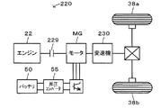
実施例のハイブリッド自動車20では、エンジン22からの動力をプラネタリギヤ30を介して駆動輪38a,38bに接続された駆動軸36に出力すると共にモータMG2からの動力を駆動軸36に出力するものとしたが、図6の変形例のハイブリッド自動車220に例示するように、駆動輪38a,38bに接続された駆動軸に変速機230を介してモータMGを取り付け、モータMGの回転軸にクラッチ229を介してエンジン22を接続する構成とし、エンジン22からの動力をモータMGの回転軸と変速機230とを介して駆動軸に出力すると共にモータMGからの動力を変速機230を介して駆動軸に出力するものとしてもよい。また、図7の変形例のハイブリッド自動車320に例示するように、エンジン22からの動力を変速機330を介して駆動輪38a,38bに接続された車軸に出力すると共にモータMGからの動力を駆動輪38a,38bに接続された車軸とは異なる車軸(図7における車輪39a,39bに接続された車軸)に出力するものとしてもよい。   In the hybrid vehicle 20 of the embodiment, the power from the engine 22 is output to the drive shaft 36 connected to the drive wheels 38a and 38b via the planetary gear 30, and the power from the motor MG2 is output to the drive shaft 36. However, as illustrated in the hybrid vehicle 220 of the modification of FIG. 6, a motor MG is attached to a drive shaft connected to the drive wheels 38 a and 38 b via a transmission 230, and a rotation shaft of the motor MG is connected to a rotation shaft via a clutch 229. The engine 22 is connected, and the power from the engine 22 is output to the drive shaft via the rotating shaft of the motor MG and the transmission 230, and the power from the motor MG is output to the drive shaft via the transmission 230. It is good also as what to do. Further, as exemplified in the hybrid vehicle 320 of the modification of FIG. 7, the power from the engine 22 is output to the axle connected to the drive wheels 38a and 38b via the transmission 330 and the power from the motor MG is driven. It is good also as what outputs to the axle different from the axle connected to wheel 38a, 38b (the axle connected to wheel 39a, 39b in FIG. 7).

実施例では、本発明を、駆動軸36にプラネタリギヤ30を介して接続されたエンジン22およびモータMG1と、駆動軸36に接続されたモータMG2と、を備えるハイブリッド自動車20に適用するものとしたが、図8の変形例の電気自動車420に例示するように、走行用の動力を出力するモータMGを備える単純な電気自動車に適用するものとしてもよい。   In the embodiment, the present invention is applied to the hybrid vehicle 20 including the engine 22 and the motor MG1 connected to the drive shaft 36 via the planetary gear 30 and the motor MG2 connected to the drive shaft 36. As illustrated in the electric vehicle 420 of the modified example of FIG. 8, the electric vehicle 420 may be applied to a simple electric vehicle including a motor MG that outputs driving power.

また、こうした自動車に限定されるものではなく、列車などの電動車両の形態としてもよいし、電動車両の電圧制御方法の形態としてもよい。   Moreover, it is not limited to such a motor vehicle, It is good also as a form of electric vehicles, such as a train, and good also as a form of the voltage control method of an electric vehicle.

実施例の主要な要素と課題を解決するための手段の欄に記載した発明の主要な要素との対応関係について説明する。実施例では、モータMG2が「モータ」に相当し、バッテリ50が「バッテリ」に相当し、昇圧コンバータ55が「昇圧コンバータ」に相当し、ハイブリッド用電子制御ユニット70が「昇圧制御手段」に相当する。   The correspondence between the main elements of the embodiment and the main elements of the invention described in the column of means for solving the problems will be described. In the embodiment, the motor MG2 corresponds to the “motor”, the battery 50 corresponds to the “battery”, the boost converter 55 corresponds to the “boost converter”, and the hybrid electronic control unit 70 corresponds to the “boost control means”. To do.

なお、実施例の主要な要素と課題を解決するための手段の欄に記載した発明の主要な要素との対応関係は、実施例が課題を解決するための手段の欄に記載した発明を実施するための形態を具体的に説明するための一例であることから、課題を解決するための手段の欄に記載した発明の要素を限定するものではない。即ち、課題を解決するための手段の欄に記載した発明についての解釈はその欄の記載に基づいて行なわれるべきものであり、実施例は課題を解決するための手段の欄に記載した発明の具体的な一例に過ぎないものである。   The correspondence between the main elements of the embodiment and the main elements of the invention described in the column of means for solving the problem is the same as that of the embodiment described in the column of means for solving the problem. Therefore, the elements of the invention described in the column of means for solving the problems are not limited. That is, the interpretation of the invention described in the column of means for solving the problems should be made based on the description of the column, and the examples are those of the invention described in the column of means for solving the problems. It is only a specific example.

以上、本発明を実施するための形態について実施例を用いて説明したが、本発明はこうした実施例に何等限定されるものではなく、本発明の要旨を逸脱しない範囲内において、種々なる形態で実施し得ることは勿論である。   As mentioned above, although the form for implementing this invention was demonstrated using the Example, this invention is not limited at all to such an Example, In the range which does not deviate from the summary of this invention, it is with various forms. Of course, it can be implemented.

本発明は、電動車両の製造産業などに利用可能である。   The present invention can be used in the manufacturing industry of electric vehicles.

20,120,220,320 ハイブリッド自動車、22 エンジン、24 エンジン用電子制御ユニット(エンジンECU)、26 クランクシャフト、30 プラネタリギヤ、36 駆動軸、37 デファレンシャルギヤ、38a,38b 駆動輪、39a,39b 車輪、40 モータ用電子制御ユニット(モータECU)、41,42 インバータ、43,44 回転位置検出センサ、50 バッテリ、52 バッテリ用電子制御ユニット(バッテリECU)、54a 駆動電圧系電力ライン、54b 電池電圧系電力ライン、55 昇圧コンバータ、57,58 コンデンサ、57a,58a 電圧センサ、70 ハイブリッド用電子制御ユニット、72 CPU、74 ROM、76 RAM、80 イグニッションスイッチ、82 シフトポジションセンサ、84 アクセルペダルポジションセンサ、86 ブレーキペダルポジションセンサ、88 車速センサ、229 クラッチ、230,330 変速機、420 電気自動車、D11〜D16,D21〜D26,D31,D32 ダイオード、L リアクトル、MG1,MG2 モータ、T11〜T16,T21〜T26,T31,T32 トランジスタ。   20, 120, 220, 320 Hybrid vehicle, 22 engine, 24 engine electronic control unit (engine ECU), 26 crankshaft, 30 planetary gear, 36 drive shaft, 37 differential gear, 38a, 38b drive wheel, 39a, 39b wheel, 40 motor electronic control unit (motor ECU), 41, 42 inverter, 43, 44 rotational position detection sensor, 50 battery, 52 battery electronic control unit (battery ECU), 54a drive voltage system power line, 54b battery voltage system power Line, 55 Boost converter, 57, 58 Capacitor, 57a, 58a Voltage sensor, 70 Hybrid electronic control unit, 72 CPU, 74 ROM, 76 RAM, 80 Ignition switch, 82 Shift switch Sensor, 84 accelerator pedal position sensor, 86 brake pedal position sensor, 88 vehicle speed sensor, 229 clutch, 230, 330 transmission, 420 electric vehicle, D11-D16, D21-D26, D31, D32 diode, L reactor, MG1, MG2 motor, T11 to T16, T21 to T26, T31, T32 transistors.

Claims (1)

駆動輪に動力を入出力するモータと、バッテリと、リアクトルとスイッチング素子とを有し前記バッテリが接続された電池電圧系の電力を昇圧して前記モータが接続された駆動電圧系に供給可能な昇圧コンバータと、前記駆動電圧系の電圧が車両の運転条件に応じた目標電圧となるよう前記昇圧コンバータを制御する昇圧制御手段と、を備える電動車両において、
前記昇圧制御手段は、前記駆動輪のスリップ時には、前記駆動電圧系の電圧が前記電池電圧系の電圧の2倍を含む所定範囲外となるよう前記昇圧コンバータを制御する手段である、
電動車両。
A motor that inputs / outputs power to / from the drive wheels, a battery, a reactor, and a switching element, boosts the power of a battery voltage system to which the battery is connected, and can be supplied to the drive voltage system to which the motor is connected In an electric vehicle comprising: a boost converter; and a boost control means for controlling the boost converter so that the voltage of the drive voltage system becomes a target voltage corresponding to a driving condition of the vehicle.
The step-up control means is means for controlling the step-up converter so that when the drive wheel slips, the voltage of the drive voltage system is outside a predetermined range including twice the voltage of the battery voltage system.
Electric vehicle.
JP2011143335A 2011-06-28 2011-06-28 Electric vehicle Withdrawn JP2013013201A (en)

Priority Applications (1)

Application Number Priority Date Filing Date Title
JP2011143335A JP2013013201A (en) 2011-06-28 2011-06-28 Electric vehicle

Applications Claiming Priority (1)

Application Number Priority Date Filing Date Title
JP2011143335A JP2013013201A (en) 2011-06-28 2011-06-28 Electric vehicle

Publications (1)

Publication Number Publication Date
JP2013013201A true JP2013013201A (en) 2013-01-17

Family

ID=47686579

Family Applications (1)

Application Number Title Priority Date Filing Date
JP2011143335A Withdrawn JP2013013201A (en) 2011-06-28 2011-06-28 Electric vehicle

Country Status (1)

Country Link
JP (1) JP2013013201A (en)

Cited By (1)

* Cited by examiner, † Cited by third party
Publication number Priority date Publication date Assignee Title
JP2015196455A (en) * 2014-04-01 2015-11-09 トヨタ自動車株式会社 Hybrid electric vehicle control system

Cited By (1)

* Cited by examiner, † Cited by third party
Publication number Priority date Publication date Assignee Title
JP2015196455A (en) * 2014-04-01 2015-11-09 トヨタ自動車株式会社 Hybrid electric vehicle control system

Similar Documents

Publication Publication Date Title
JP4424428B2 (en) Electric motor drive control device, vehicle including the same, and electric motor drive control method
JP5772782B2 (en) vehicle
CN108068799B (en) Hybrid vehicle
JP4123269B2 (en) POWER OUTPUT DEVICE, VEHICLE MOUNTING THE SAME, AND METHOD FOR CONTROLLING POWER OUTPUT DEVICE
US9932032B2 (en) Hybrid vehicle
JP2021084537A (en) Hybrid vehicle
JP6575544B2 (en) Hybrid car
JP5221444B2 (en) Buck-boost converter control device, hybrid vehicle equipped with the same, and buck-boost converter control method
JP5370291B2 (en) vehicle
JP5341572B2 (en) Control method for buck-boost converter
JP5211743B2 (en) POWER SUPPLY DEVICE, VEHICLE MOUNTING THE SAME, AND CONTROL METHOD FOR POWER SUPPLY DEVICE
JP2012135124A (en) Vehicle
JP2018184133A (en) Hybrid vehicle
JP5412839B2 (en) Power supply device, control method therefor, and vehicle
JP2011162130A (en) Hybrid vehicle and control method for the same
JP6489100B2 (en) Hybrid car
JP2018144687A (en) Hybrid vehicle
CN108725426B (en) Hybrid vehicle and control method thereof
JP2012222907A (en) Electric vehicle
JP6607217B2 (en) Hybrid car
JP2013013201A (en) Electric vehicle
JP2016100965A (en) Electric vehicle
JP2013124084A (en) Hybrid vehicle
JP2012192769A (en) Electric vehicle
JP2011152834A (en) Vehicle, and method for controlling the same

Legal Events

Date Code Title Description
A300 Application deemed to be withdrawn because no request for examination was validly filed

Free format text: JAPANESE INTERMEDIATE CODE: A300

Effective date: 20140902