JP2012520351A - Improved mechanical properties of epoxies filled with functionalized carbon nanotubes - Google Patents
Improved mechanical properties of epoxies filled with functionalized carbon nanotubes Download PDFInfo
- Publication number
- JP2012520351A JP2012520351A JP2011553319A JP2011553319A JP2012520351A JP 2012520351 A JP2012520351 A JP 2012520351A JP 2011553319 A JP2011553319 A JP 2011553319A JP 2011553319 A JP2011553319 A JP 2011553319A JP 2012520351 A JP2012520351 A JP 2012520351A
- Authority
- JP
- Japan
- Prior art keywords
- epoxy
- carbon nanotubes
- ozone
- cnt
- mixture
- Prior art date
- Legal status (The legal status is an assumption and is not a legal conclusion. Google has not performed a legal analysis and makes no representation as to the accuracy of the status listed.)
- Withdrawn
Links
Images


Classifications
-
- C—CHEMISTRY; METALLURGY
- C08—ORGANIC MACROMOLECULAR COMPOUNDS; THEIR PREPARATION OR CHEMICAL WORKING-UP; COMPOSITIONS BASED THEREON
- C08L—COMPOSITIONS OF MACROMOLECULAR COMPOUNDS
- C08L63/00—Compositions of epoxy resins; Compositions of derivatives of epoxy resins
-
- C—CHEMISTRY; METALLURGY
- C08—ORGANIC MACROMOLECULAR COMPOUNDS; THEIR PREPARATION OR CHEMICAL WORKING-UP; COMPOSITIONS BASED THEREON
- C08G—MACROMOLECULAR COMPOUNDS OBTAINED OTHERWISE THAN BY REACTIONS ONLY INVOLVING UNSATURATED CARBON-TO-CARBON BONDS
- C08G59/00—Polycondensates containing more than one epoxy group per molecule; Macromolecules obtained by polymerising compounds containing more than one epoxy group per molecule using curing agents or catalysts which react with the epoxy groups
- C08G59/18—Macromolecules obtained by polymerising compounds containing more than one epoxy group per molecule using curing agents or catalysts which react with the epoxy groups ; e.g. general methods of curing
- C08G59/40—Macromolecules obtained by polymerising compounds containing more than one epoxy group per molecule using curing agents or catalysts which react with the epoxy groups ; e.g. general methods of curing characterised by the curing agents used
- C08G59/50—Amines
- C08G59/5033—Amines aromatic
-
- C—CHEMISTRY; METALLURGY
- C08—ORGANIC MACROMOLECULAR COMPOUNDS; THEIR PREPARATION OR CHEMICAL WORKING-UP; COMPOSITIONS BASED THEREON
- C08J—WORKING-UP; GENERAL PROCESSES OF COMPOUNDING; AFTER-TREATMENT NOT COVERED BY SUBCLASSES C08B, C08C, C08F, C08G or C08H
- C08J5/00—Manufacture of articles or shaped materials containing macromolecular substances
- C08J5/005—Reinforced macromolecular compounds with nanosized materials, e.g. nanoparticles, nanofibres, nanotubes, nanowires, nanorods or nanolayered materials
-
- C—CHEMISTRY; METALLURGY
- C08—ORGANIC MACROMOLECULAR COMPOUNDS; THEIR PREPARATION OR CHEMICAL WORKING-UP; COMPOSITIONS BASED THEREON
- C08K—Use of inorganic or non-macromolecular organic substances as compounding ingredients
- C08K3/00—Use of inorganic substances as compounding ingredients
- C08K3/02—Elements
- C08K3/04—Carbon
- C08K3/041—Carbon nanotubes
-
- C—CHEMISTRY; METALLURGY
- C09—DYES; PAINTS; POLISHES; NATURAL RESINS; ADHESIVES; COMPOSITIONS NOT OTHERWISE PROVIDED FOR; APPLICATIONS OF MATERIALS NOT OTHERWISE PROVIDED FOR
- C09D—COATING COMPOSITIONS, e.g. PAINTS, VARNISHES OR LACQUERS; FILLING PASTES; CHEMICAL PAINT OR INK REMOVERS; INKS; CORRECTING FLUIDS; WOODSTAINS; PASTES OR SOLIDS FOR COLOURING OR PRINTING; USE OF MATERIALS THEREFOR
- C09D163/00—Coating compositions based on epoxy resins; Coating compositions based on derivatives of epoxy resins
-
- C—CHEMISTRY; METALLURGY
- C08—ORGANIC MACROMOLECULAR COMPOUNDS; THEIR PREPARATION OR CHEMICAL WORKING-UP; COMPOSITIONS BASED THEREON
- C08K—Use of inorganic or non-macromolecular organic substances as compounding ingredients
- C08K3/00—Use of inorganic substances as compounding ingredients
- C08K3/02—Elements
- C08K3/04—Carbon
-
- C—CHEMISTRY; METALLURGY
- C08—ORGANIC MACROMOLECULAR COMPOUNDS; THEIR PREPARATION OR CHEMICAL WORKING-UP; COMPOSITIONS BASED THEREON
- C08K—Use of inorganic or non-macromolecular organic substances as compounding ingredients
- C08K7/00—Use of ingredients characterised by shape
- C08K7/22—Expanded, porous or hollow particles
-
- C—CHEMISTRY; METALLURGY
- C08—ORGANIC MACROMOLECULAR COMPOUNDS; THEIR PREPARATION OR CHEMICAL WORKING-UP; COMPOSITIONS BASED THEREON
- C08L—COMPOSITIONS OF MACROMOLECULAR COMPOUNDS
- C08L2666/00—Composition of polymers characterized by a further compound in the blend, being organic macromolecular compounds, natural resins, waxes or and bituminous materials, non-macromolecular organic substances, inorganic substances or characterized by their function in the composition
- C08L2666/02—Organic macromolecular compounds, natural resins, waxes or and bituminous materials
- C08L2666/04—Macromolecular compounds according to groups C08L7/00 - C08L49/00, or C08L55/00 - C08L57/00; Derivatives thereof
Abstract
本発明は、カーボンナノチューブ(CNT)のエポキシマトリックスへの組み込みおよびそれによるエポキシ系CNTナノ複合材料を製造の方法に関する。初期およびオゾン処理CNTはいずれも、常に、この方法により樹脂中へ均質に分散される。初期CNT(p−MWCNT)と比べて、オゾン処理CNT(f−MWCNT)は、エポキシ樹脂内で機械特性についてかなり向上させる。 The present invention relates to the incorporation of carbon nanotubes (CNT) into an epoxy matrix and thereby a method for producing epoxy-based CNT nanocomposites. Both the initial and ozone treated CNTs are always homogeneously dispersed in the resin by this method. Compared to the initial CNT (p-MWCNT), the ozone-treated CNT (f-MWCNT) significantly improves the mechanical properties within the epoxy resin.
Description
本発明は、カーボンナノチューブ(CNT)のエポキシマトリックスへの組み込みおよびそれによるエポキシ系CNTナノ複合材料の製造方法に関する。初期およびオゾン処理CNTはいずれも、常に、この方法により樹脂中へ均質に分散される。初期CNT(p−MWCNT)と比べて、オゾン処理CNT(f−MWCNT)は、エポキシ樹脂内で機械特性をかなり向上させる。 The present invention relates to the incorporation of carbon nanotubes (CNTs) into an epoxy matrix and thereby the production of epoxy-based CNT nanocomposites. Both the initial and ozone treated CNTs are always homogeneously dispersed in the resin by this method. Compared to initial CNT (p-MWCNT), ozone-treated CNT (f-MWCNT) significantly improves mechanical properties within the epoxy resin.
多くの研究者は、Iijimaにより1991年に(Nature 1991年、第354巻、第56頁)カーボンナノチューブ(CNT)が発見されて以来、カーボンナノチューブに注目してきた。単壁カーボンナノチューブ(SWCNT)が、通常0.7〜2nmの範囲での直径を有する完全な円筒へと丸くなったグラファイト格子の単一層からなるのに対し、多壁カーボンナノチューブ(MWCNT)は、より大きな直径を通常有する幾つかの円筒状シェルからなる。特有の構造は、CNTに優れた熱安定性および際立った機械特性、電気特性および構造特性を付与する。数十年にわたって、ポリマー材料の機械特性および電気特性を向上させるために、多くの注意がCNTの利用に払われてきた(WO2008057623、WO2006096203、WO2003040026、Adv Mater 2004年、第16巻、第58頁)。 Many researchers have focused on carbon nanotubes since the discovery of carbon nanotubes (CNTs) in 1991 (Nature 1991, 354, 56) by Iijima. Single-walled carbon nanotubes (SWCNTs) consist of a single layer of a graphite lattice rounded into a perfect cylinder, usually with a diameter in the range of 0.7-2 nm, whereas multi-walled carbon nanotubes (MWCNTs) It consists of several cylindrical shells usually having a larger diameter. The unique structure imparts excellent thermal stability and outstanding mechanical, electrical and structural properties to CNTs. Over the decades, much attention has been devoted to the use of CNTs to improve the mechanical and electrical properties of polymer materials (WO2008057623, WO2006096203, WO2003040026, Adv Mater 2004, Vol. 16, p. 58). ).
先行技術によれば、カーボンナノチューブは主に、3〜100nmの直径および該直径の数倍の長さを有する円筒状カーボンチューブであると理解される。該チューブは、配向炭素原子の1以上の層からなり、異なった形態のコアを有する。また、該カーボンナノチューブは、例えば「カーボンフィブリル」または「中空カーボンファイバー」とも称される。 According to the prior art, carbon nanotubes are mainly understood to be cylindrical carbon tubes having a diameter of 3 to 100 nm and a length several times the diameter. The tube consists of one or more layers of oriented carbon atoms and has differently shaped cores. The carbon nanotube is also referred to as “carbon fibril” or “hollow carbon fiber”, for example.
カーボンナノチューブは、専門文献において長い間知られている。Iijima(出版物:S.Iijima、Nature第354巻、第56〜58頁、1991年)がナノチューブを発見したと一般に考えられるが、これらの物質、特に、複数のグラファイト層を有する繊維状グラファイト物質は、1970年代または1980年代初期から知られている。TatesおよびBaker(GB1469930A1、1977年およびEP56004A2、1982年)は、炭化水素の触媒分解からの極めて微細な繊維状炭素の堆積物を最初に記載した。しかしながら、短鎖状炭化水素に基づいて製造された炭素フィラメントは、その直径についてさらに詳細に特徴付けられていない。 Carbon nanotubes have long been known in the specialist literature. Although Iijima (publication: S. Ijima, Nature 354, pp. 56-58, 1991) is generally thought to have discovered nanotubes, these materials, particularly fibrous graphite materials having multiple graphite layers Has been known since the 1970s or early 1980s. Tates and Baker (GB14669930A1, 1977 and EP56004A2, 1982) first described very fine fibrous carbon deposits from catalytic cracking of hydrocarbons. However, carbon filaments made on the basis of short chain hydrocarbons have not been characterized in more detail for their diameter.
従来法によるこれらのチューブの構造は、円筒型である。円筒構造の場合、単壁モノカーボンナノチューブと多壁円筒状カーボンナノチューブとの間で区別される。その製造のための従来法は、例えばアーク放電法、レーザーアブレーション法、化学蒸着法(CVD法)および触媒化学蒸着法(CCVD法)である。 The structure of these tubes according to the conventional method is cylindrical. In the case of a cylindrical structure, a distinction is made between single-walled monocarbon nanotubes and multi-walled cylindrical carbon nanotubes. Conventional methods for its production are, for example, arc discharge, laser ablation, chemical vapor deposition (CVD) and catalytic chemical vapor deposition (CCVD).
また、上記円筒状カーボンナノチューブは、アーク放電法により製造することもできる。Iijima、Nature 第354巻、1991年、第56〜58頁は、アーク放電法による、丸くなって途切れのない閉じた円筒を形成し、および互いに入れ子になった2以上のグラフェン層からなるカーボンチューブの形成について報告する。キラル配置およびアキラル配置が、カーボンファイバーの縦軸に沿って、回転ベクトルに応じて可能である。 The cylindrical carbon nanotube can also be produced by an arc discharge method. Iijima, Nature 354, 1991, pp. 56-58 is a carbon tube comprising two or more graphene layers nested in each other to form a round and uninterrupted closed cylinder by the arc discharge method. Report on the formation of Chiral and achiral configurations are possible depending on the rotation vector along the longitudinal axis of the carbon fiber.
凝集グラフェン層(いわゆるスクロール型)または破壊グラフェン層(いわゆるオニオン型)がナノチューブの構造のための基礎を形成するカーボンチューブの類似構造は、Bacon等、J.Appl.Phys.第34巻、1960年、第283〜290頁により最初に記載された。該構造は通常、スクロール型と称される。その後、類似構造がまた、Zhou等、Science、第263巻、1994年、第1744〜1747頁により、およびLavin等、Carbon 第40巻、2002年、第1123〜1130頁により見出された。 Similar structures of carbon tubes in which agglomerated graphene layers (so-called scroll type) or destructive graphene layers (so-called onion type) form the basis for the structure of nanotubes are described in Bacon et al. Appl. Phys. 34, 1960, first described by pages 283-290. This structure is usually called a scroll type. Later, similar structures were also found by Zhou et al., Science, 263, 1994, 1744-1747, and Lavin et al., Carbon 40, 2002, 1123-1130.
エポキシは、硬化の際のその低収縮、優れた寸法安定性、良好な防食性および際立った接着性のために、工業においてよく用いられる熱硬化性ポリマーの1つである。しかしながら、エポキシ樹脂の脆い特性は、構造材料としてのその用途について、特に電気、航空および宇宙工業に用いる高性能用途について大きな欠点である。エポキシ樹脂のCNTによる補強および強靱化は、好ましい方法に見えるが、どのようにしてCNTをポリマーマトリックス中へ均質に分散させるか、およびどのようにしてCNTとポリマーマトリックスとの間での良好な接着を実現させるのかがこれまでの大きな課題である。 Epoxy is one of the thermosetting polymers commonly used in the industry because of its low shrinkage upon curing, excellent dimensional stability, good corrosion protection and outstanding adhesion. However, the brittle nature of epoxy resins is a major drawback for their use as structural materials, especially for high performance applications used in the electrical, aeronautical and space industries. Reinforcement and toughening of epoxy resin with CNT appears to be the preferred method, but how to disperse CNT homogeneously in the polymer matrix and how to achieve good adhesion between CNT and polymer matrix Realizing this is a major challenge so far.
大きなアスペクト比を有するCNTは、高度に絡み合い、従って、大きな凝集体を形成し、得られたエポキシ−CNT複合材料の機械的および電気的特性をいずれも損なわせる(Adv Mater 2000年、第12巻、第750頁およびAppl Phys Lett 1998年、第73巻、第3842頁)。 CNTs with large aspect ratios are highly entangled, thus forming large aggregates and detracting from the mechanical and electrical properties of the resulting epoxy-CNT composite (Adv Mater 2000, Vol. 12) 750, and Appl Phys Lett 1998, 73, 3842).
幾つかの方法が、得られるナノ複合材料の向上した機械的、電気的および熱的特性に恩恵をもたらすポリマーマトリックス中へCNTを均質に分散させるために、CNT凝集体を効率的に細分化するために数年にわたって既に試されてきた。これらの一つは、機械混合、すなわちCNTフィラーをポリマー中へせん断強撹拌、例えば高速混合等により添加することである(WO2008054034、WO2008034939、Polymer 2006年、第47巻、第293頁、Comp Sci Tech 2004年、第64巻、第2363頁)。超音波処理の使用は、物理的混合を組み合わせるかどうかに拘わらず、向上した分散体を得るのに役立つことがある(Comp Sci Tech 2009年、第69巻、第335頁、SAMPE Conference Proceedings 2008年、第53巻、第329頁、Recent Adv Textile Comp Procs Intern Conf Textile Comp、第9版、Newark US、2008年10月13〜15日、J Mater Sci 2008年、第53巻、第5頁、Mater Sci Eng A:Struct Mater Props Microstruct Proc 2008年、第A475巻、第157頁)。 Several methods efficiently fragment CNT aggregates to uniformly disperse CNTs in a polymer matrix that benefits the improved mechanical, electrical and thermal properties of the resulting nanocomposites Has already been tried for several years. One of these is mechanical mixing, that is, adding CNT filler into the polymer by strong shearing stirring, such as high speed mixing (WO2008054034, WO20080349939, Polymer 2006, 47, 293, Comp Sci Tech). 2004, 64, 2363). The use of sonication may help to obtain improved dispersions with or without physical mixing (Comp Sci Tech 2009, 69, 335, SAMPE Conference Processings 2008). 53, p. 329, Recent Adv Textile Comp Procs, International Conf Textile Comp, 9th edition, Newark US, Oct. 13-15, 2008, J Mater Sci 2008, Vol. 53, p. 5, Mater Sci Eng A: Struct Mater Props Microstruct Proc 2008, A475, 157).
上記処理の間、適当な有機溶媒および界面活性剤(WO2006096203、SAMPE 2002 Symp&Exhi、Chem Mater、2000年、第12巻、第1049頁、Gaofenzi Cailiao Kexue Yu Gongcheng 2008年、第24巻、第134頁)は、CNTポリマーブレンドを希釈し、2相の相溶性を増加させることを必要とし得る。しかしながら、強力な物理混合および超音波は、CNTの絡み合いを実際に細分化させるのに十分ではないことが記載されている(Polymer 1999年、第40巻、第5967頁、AIP Conf Proc 2000年、第N544巻、第521頁、Appl Phys Lett 2002年、第80巻、第2767頁)。 During the above treatment, suitable organic solvents and surfactants (WO2006096203, SAMPE 2002 Symp & Exhi, Chem Mater, 2000, Vol. 12, p. 1049, Gaofenzi Cagliao Kexue Yu Gongheng 2008, Vol. 24, p. 134) May require diluting the CNT polymer blend to increase the compatibility of the two phases. However, it has been described that strong physical mixing and ultrasound are not sufficient to actually subdivide the entanglement of CNTs (Polymer 1999, 40, 5967, AIP Conf Proc 2000, N544, 521, Appl Phys Lett 2002, 80, 2767).
均質なCNTのポリマーマトリックス中への分散に加えて、グラファイトCNTおよび有機ポリマーホスト間の相互作用もまた、ポリマー複合材料を強化する極めて重要な役割を果たす(WO2004070349、US2006202168、WO2005014708、US2007259994)。幾つかの試みが、無機フィラーおよび有機ホスト間での共有結合性相互作用を、「ポリソープ」と同様のポリマー鎖を含有するピレンセグメント(Chem Comm 2003年、第23巻、第2904頁、Chem Mater 2004年、第16巻、第4005頁、J Am Chem Soc 2006年、第128巻、第6556頁)またはポルフィリン(Adv Mater 2005年、第17巻、第871頁)を用いるπ−π超分子相互作用により向上させるためになされてきた。化学基またはグラフトポリマーを有する共有結合的に官能化されたCNTは、効率的に、分散を促進させ、良好なCNTポリマーの界面接着を確保する他の方法である(WO2007115162、US2008090951、WO2005028174、Nano Lett 2003年、第3巻、第1107頁、Adv Funct Mter 2004年、第14巻、第643頁、Compsites Part A:Appl Sci Manufc 2007年、第38A巻、第1331頁、Nanotechnology 2006年、第17巻、第155頁、SAMPE Conference Proceedings 2008年、第53巻、5&40、Comps Sci Tech 2008年、第68巻、第3259頁、Comps Sci Tech 2008年、第67巻、第3331頁、J Mater Sci 2008年、第43巻、第2653頁、Chem Mater 2007年、第19巻、第308頁、Eur Polym J 2006年、第42巻、第2765頁、J Appl Polym Sci 2006年、第100巻、第97頁、Polym Rev 2007年、第47巻、第265頁)。
In addition to the dispersion of homogeneous CNTs in the polymer matrix, the interaction between the graphite CNTs and the organic polymer host also plays an extremely important role in strengthening the polymer composite (WO2004070349, US2006202168, WO2005014708, US2007259944). Several attempts have been made to link covalent interactions between inorganic fillers and organic hosts to pyrene segments containing polymer chains similar to "Polysoap" (Chem Comm 2003, 23, 2904, Chem Mater. 2004, Vol. 16, p. 4005, J Am Chem Soc 2006, Vol. 128, p. 6556) or porphyrin (Adv Mater 2005, Vol. 17, p. 871). It has been made to improve by action. Covalently functionalized CNTs with chemical groups or graft polymers are another way to efficiently promote dispersion and ensure good interfacial adhesion of CNT polymers (WO200007115162, US2008090951, WO20050828174, Nano Lett 2003, 3rd, 1107, Adv Funct Mter 2004, 14th, 643, Composites Part A: Appl Sci Manufc 2007, 38A, 1331, Nanotechnology 17 2006. Volume, 155, SAMPE Conference Proceedings 2008,
上記方法は、効率的であると分かるが、工業的実施について深刻な制限が存在する。溶媒の特別な費用に拘わらず、有機溶媒を用いてポリマー中へCNTを分散させることも、溶媒を硬化前にポリマーから完全に除去しなければならないので、時間およびエネルギーを消費する。さらに、有機溶媒は、環境および健康に有害な作用をもたらす。また、同様の問題が、CNTを官能化する場合に、濃縮HNO3/H2SO4またはH2O2を用いて液体強酸化剤として用いる際、存在する。界面活性剤を用いてCNT分散体を向上させることも、該界面活性剤が、得られるナノ複合材料中に残存し、性能を低下させるので、問題となることがある。CNTの共有結合グラフトポリマーでの多段階変性は、複雑な化学手法および高い費用のために工業的用途に適していない。 While the above method proves to be efficient, there are serious limitations on industrial implementation. Despite the special cost of the solvent, dispersing the CNTs into the polymer using an organic solvent also consumes time and energy because the solvent must be completely removed from the polymer before curing. In addition, organic solvents have detrimental effects on the environment and health. A similar problem exists when using CNTs as a liquid strong oxidant using concentrated HNO 3 / H 2 SO 4 or H 2 O 2 when functionalizing CNTs. Improving the CNT dispersion using a surfactant can also be problematic because the surfactant remains in the resulting nanocomposite material and degrades performance. Multi-step modification of CNTs with covalent graft polymers is not suitable for industrial applications due to complex chemical techniques and high costs.
本発明では、オゾン処理多壁カーボンナノチューブ(MWCNT)を強化フィラーとして用いてエポキシ樹脂の機械的および電気的特性を向上させた。好ましくは、水蒸気の存在下でのオゾン分解は、MWCNTを効率的に官能基化させる。液体強酸化剤を用いる従来の酸化法と比べて、オゾン分解は、処理がより一層便利であり、環境に優しく、並びに費用が安い。表面変性でのMWCNTは、エポキシ樹脂と、最適な処理条件下でエポキシ樹脂と機械的にブレンドし、溶媒を方法全体において存在させない。この方法により、満足のいくMWCNTのエポキシへの均質な分散が、特に本発明のオゾン処理MWCNTについて得られる。MWCNT/エポキシナノ複合材料は、比較的低MWCNT含有量でさえ、純エポキシ樹脂と比べて、著しく向上した機械特性を示す。 In the present invention, ozone-treated multi-walled carbon nanotubes (MWCNT) are used as reinforcing fillers to improve the mechanical and electrical properties of the epoxy resin. Preferably, ozonolysis in the presence of water vapor efficiently functionalizes the MWCNT. Compared to conventional oxidation methods using liquid strong oxidants, ozonolysis is much more convenient to process, environmentally friendly and cheap. MWCNTs with surface modification are mechanically blended with the epoxy resin and the epoxy resin under optimal processing conditions, and no solvent is present throughout the process. By this method, a satisfactory homogeneous dispersion of MWCNTs in the epoxy is obtained, especially for the ozone-treated MWCNTs of the present invention. The MWCNT / epoxy nanocomposite exhibits significantly improved mechanical properties compared to pure epoxy resin, even at relatively low MWCNT content.
本発明は、強化CNTエポキシポリマー複合材料をもたらす、CNT凝集体の水蒸気の存在下でのオゾン分解による効率的な官能基化およびそのオゾン処理カーボンナノチューブ(CNT)のエポキシ樹脂への細分化方法を提供することである。本発明のある実施態様は、CNTのエポキシポリマーマトリックスへの組み込み法およびCNT/EPナノ複合材料を製造する方法を提供する。本発明のCNTは、約100nm以下の少なくとも1つの寸法を有し、ポリマーマトリックス中に実質的に均質に分散させる。 The present invention relates to an efficient functionalization by ozonolysis of CNT aggregates in the presence of water vapor and a method for subdividing the ozone-treated carbon nanotubes (CNTs) into epoxy resins resulting in a reinforced CNT epoxy polymer composite. Is to provide. Certain embodiments of the present invention provide a method for incorporating CNTs into an epoxy polymer matrix and for producing CNT / EP nanocomposites. The CNTs of the present invention have at least one dimension of about 100 nm or less and are substantially homogeneously dispersed in the polymer matrix.
本発明の主題は、エポキシポリマー、カーボンナノチューブおよび必要に応じて硬化剤を含み、該カーボンナノチューブが、以下の工程:
a)カーボンナノチューブを反応ゾーン中へ設置する工程、
b)オゾン、酸素および水の混合物を前記カーボンナノチューブへ通過させる工程
を含む酸素/オゾンによる気相中での同時処理により酸化されていることを特徴とする複合材料である。
The subject of the present invention comprises an epoxy polymer, carbon nanotubes and optionally a curing agent, the carbon nanotubes comprising the following steps:
a) installing a carbon nanotube into the reaction zone;
b) A composite material characterized by being oxidized by simultaneous treatment in the gas phase with oxygen / ozone including a step of passing a mixture of ozone, oxygen and water through the carbon nanotubes.
好ましい材料は、オゾン、酸素および水の混合物が、工程b)においてカーボンナノチューブの凝集体を連続的に通過することを特徴とする。 A preferred material is characterized in that a mixture of ozone, oxygen and water passes continuously through the carbon nanotube aggregates in step b).
反応ゾーンにおける温度は、工程b)において、特に少なくとも200℃、好ましくは少なくとも120℃、より好ましくは0〜100℃、さらに好ましくは10〜60℃である。 The temperature in the reaction zone is in particular in step b) at least 200 ° C., preferably at least 120 ° C., more preferably 0-100 ° C., even more preferably 10-60 ° C.
カーボンナノチューブのオゾン分解の反応時間は、工程b)において、特に120分まで、好ましくは60分まで、より好ましくは30分までである。 The reaction time for the ozonolysis of the carbon nanotubes is particularly up to 120 minutes, preferably up to 60 minutes, more preferably up to 30 minutes in step b).
カーボンナノチューブの暴露は、工程b)において、特に、1体積%〜約11体積%のオゾンの割合を含むオゾン/酸素混合物を用いて行う。 The exposure of carbon nanotubes is carried out in step b), in particular using an ozone / oxygen mixture containing a proportion of ozone of 1% to about 11% by volume.
オゾン、酸素および水の混合物の流速は、工程b)において、特に、カーボンナノチューブ1g当たり約100L/時〜約1000L/時、好ましくは約100L/時〜約200L/時である。 The flow rate of the mixture of ozone, oxygen and water in step b) is in particular from about 100 L / hour to about 1000 L / hour, preferably from about 100 L / hour to about 200 L / hour, per gram of carbon nanotubes.
水蒸気の相対湿度は、工程b)における反応ゾーンにおいて、特に100%まで、好ましくは少なくとも10%〜100%まで、特に好ましくは10%〜90%である。 The relative humidity of the water vapor is in particular up to 100%, preferably at least 10% to 100%, particularly preferably 10% to 90% in the reaction zone in step b).
さらに好ましい物質は、カーボンナノチューブの量が、複合材料の0.01〜5重量%、好ましくは0.05〜3重量%、特に好ましくは0.1〜1重量%であることを特徴とする。 Further preferred substances are characterized in that the amount of carbon nanotubes is 0.01-5% by weight of the composite material, preferably 0.05-3% by weight, particularly preferably 0.1-1% by weight.
本発明のさらなる好ましい実施態様では、上記材料は、ビスフェノールAのジグリシジルエーテルエポキシ(DGEBA)、ノボラックエポキシ、臭素化エポキシポリマーおよびこれらの混合物からなる群から選択されるエポキシポリマーを含んでなる。 In a further preferred embodiment of the invention, the material comprises an epoxy polymer selected from the group consisting of diglycidyl ether epoxy of bisphenol A (DGEBA), novolac epoxy, brominated epoxy polymer and mixtures thereof.
さらなる好ましい実施態様では、上記材料は、硬化剤がジアミノジフェニルスルホン(DDS)、ジアミノジフェニルメタン(DDM)等を含む芳香族アミン硬化剤の群から選択されることを特徴とする。 In a further preferred embodiment, the material is characterized in that the curing agent is selected from the group of aromatic amine curing agents including diaminodiphenylsulfone (DDS), diaminodiphenylmethane (DDM) and the like.
本発明の他の主題は、以下の工程:1)オゾン処理CNTをエポキシ樹脂中へ機械的に混合してブレンドを形成する工程;2)前記ブレンドを高剪断系により分散してCNT/エポキシマスターバッチを形成する工程;3)硬化剤およびエポキシ樹脂の特定量を前記マスターバッチに添加して分散体を形成する工程;4)前記分散体を更に機械的に混合する工程;5)該混合物を脱気および硬化してCNT/エポキシ複合材料を形成する工程を含み、前記CNTを、エポキシマトリックス中へ分散しおよび組み込む製造方法を提供する。 Another subject of the invention is the following steps: 1) mechanically mixing ozone treated CNTs into an epoxy resin to form a blend; 2) dispersing the blend with a high shear system to produce a CNT / epoxy master. Forming a batch; 3) adding a specific amount of curing agent and epoxy resin to the masterbatch to form a dispersion; 4) further mechanically mixing the dispersion; 5) adding the mixture to the masterbatch; A manufacturing method is provided that includes degassing and curing to form a CNT / epoxy composite, wherein the CNTs are dispersed and incorporated into an epoxy matrix.
本発明の更なる主題は、風力タービン、車両および架橋建築部品およびスポーツ用品の製造のための新規な複合材料の使用である。 A further subject of the present invention is the use of novel composite materials for the production of wind turbines, vehicles and bridged building parts and sporting goods.
本発明のさらなる実施態様は、オゾン処理CNTで強化されたナノ複合材料を提供する。例えば、該複合材料は、エポキシ樹脂、およびCNTの少量%、例えば約0.1〜1.0重量%を含み得る。 A further embodiment of the invention provides nanocomposites reinforced with ozone treated CNTs. For example, the composite material may include an epoxy resin and a small percentage of CNTs, such as about 0.1 to 1.0% by weight.
本発明の他の実施態様では、約10%以上の極限強度を上昇させ、および約10%以上の破断点伸びを上昇させる任意の適当なCNT充填を用い得る。約50%以上任意の適当なCNT充填量は、臨界歪み応力度(KIC)の約50%以上の強化、および約130%以上の平面歪み臨界応力エネルギー解放率(GIC)の約130%以上の強化をもたらす任意の適当なCNT充填を用い得る。 In other embodiments of the invention, any suitable CNT loading that increases the ultimate strength of about 10% or more and increases the elongation at break of about 10% or more may be used. Any suitable CNT loading of about 50% or more is about 50% enhancement of critical strain stress degree (K IC ) and about 130% of plane strain critical stress energy release rate (G IC ) of about 130% or more. Any suitable CNT filling that provides the above enhancement can be used.
本発明の他の実施態様では、約20%以上の極限強度の上昇および約80%以上の破断点伸びの上昇を生じさせる任意の適当なオゾン処理CNT充填を用い得る。KICの約30%以上の強化およびGICの約2倍以上の強化をもたらす任意の適当なオゾン処理CNT充填を用い得る。 In other embodiments of the invention, any suitable ozonated CNT fill that produces an ultimate strength increase of about 20% or greater and an elongation at break of about 80% or greater may be used. Any suitable ozonated CNT filling that provides an enhancement of about 30% or more of the K IC and an enhancement of about 2 or more of the G IC can be used.
本発明は、CNTをエポキシマトリックス中へ組み込む方法および該方法により製造されたCNT/エポキシナノ複合材料に関する。該CNTは、約100nm以下の少なくとも1つの寸法を有し、マトリックス材料中に実質的に均質に分散される。 The present invention relates to a method of incorporating CNTs into an epoxy matrix and to CNT / epoxy nanocomposites produced by the method. The CNTs have at least one dimension of about 100 nm or less and are substantially homogeneously dispersed in the matrix material.
本発明のカーボンナノチューブは、多壁カーボンナノチューブ(MWCNT)であり、上記CNTは、様々な長さ、直径、チューブ壁の数等であってよい。単壁カーボンナノチューブ(SWCNT)も本発明に適当であり得ることは注目すべき点である。 The carbon nanotubes of the present invention are multi-walled carbon nanotubes (MWCNT), and the CNTs may have various lengths, diameters, tube wall numbers, and the like. It should be noted that single-walled carbon nanotubes (SWCNT) may also be suitable for the present invention.
好ましくは、高純度を有するカーボンナノチューブを、本発明に用いる。ここで、該純度は、カーボンナノチューブと任意の汚染物質、例えば金属残渣および非晶質不純物等との混合物におけるカーボンナノチューブのパーセンテージのことである。本発明では、カーボンナノチューブの純度は、95%を越え、好ましくは98%を越える。 Preferably, carbon nanotubes having high purity are used in the present invention. Here, the purity refers to the percentage of carbon nanotubes in a mixture of carbon nanotubes and any contaminants such as metal residues and amorphous impurities. In the present invention, the purity of the carbon nanotubes is over 95%, preferably over 98%.
本発明のカーボンナノチューブは、単壁カーボンナノチューブ(SWCNT)または二重壁カーボンナノチューブ(DWCNT)または多壁カーボンナノチューブ(MWCNT)である。これらは、魚の骨または血小板構造またはグラフェンまたは黒鉛シートにおけるカーボンナノファイバーであってもよい。これらの構造の全ては、黒鉛層において窒素、ホウ素等のようなヘテロ原子を含み得る。 The carbon nanotube of the present invention is a single-walled carbon nanotube (SWCNT), a double-walled carbon nanotube (DWCNT), or a multi-walled carbon nanotube (MWCNT). These may be fish bone or platelet structures or carbon nanofibers in graphene or graphite sheets. All of these structures can contain heteroatoms such as nitrogen, boron, etc. in the graphite layer.
本発明によるカーボンナノチューブは、円筒型、スクロール型またはオニオン型構造に基づく全ての単壁または多壁カーボンナノチューブ構造を含む。好ましいのは、円筒型またはスクロール型の多壁カーボンナノチューブまたはこれらの混合物である。 The carbon nanotubes according to the invention include all single-walled or multi-walled carbon nanotube structures based on cylindrical, scroll or onion structures. Preferable are cylindrical or scroll type multi-walled carbon nanotubes or a mixture thereof.
好ましいのは、5より大きい、より好ましくは100より大きい長さと直径の割合を有するカーボンナノチューブの使用である。 Preference is given to the use of carbon nanotubes having a length and diameter ratio greater than 5, more preferably greater than 100.
より好ましくは、凝集体の形態でのカーボンナノファイバーを用い、該凝集体は、0.05〜5mm、好ましくは0.1〜2mm、より好ましくは0.2〜1mmの範囲での平均径を有する。 More preferably, carbon nanofibers in the form of aggregates are used, the aggregates having an average diameter in the range of 0.05-5 mm, preferably 0.1-2 mm, more preferably 0.2-1 mm. Have.
カーボンナノチューブの平均径は、3〜100nm、好ましくは5〜80nm、特に好ましくは6〜60nmである。 The average diameter of the carbon nanotube is 3 to 100 nm, preferably 5 to 80 nm, and particularly preferably 6 to 60 nm.
単一連続または不連続のグラフェン層を有する文献に記載の先行技術のCNTとは対照的に、カーボンの新規な形態では、複数のグラフェン層が組み合わさって丸くなった形態(マルチスクロール型)である積み重なりを形成する。このようなカーボンナノチューブおよびカーボンチューブ凝集体は、例えば公式出願番号102007044031.8を有する未公開独国特許出願の主題である(CNTおよびその製造に関するその内容はここに本出願の開示として含まれる)。このCNT構造は、単壁円筒状カーボンナノチューブ(円筒状SWNT)に対して多壁円筒状モノカーボンナノチューブ(円筒状MWNT)が振る舞うように、構造について単純スクロール型の既知のカーボンナノチューブに対して振る舞う。 In contrast to the prior art CNTs described in the literature with a single continuous or discontinuous graphene layer, the new form of carbon is a combined form of multiple graphene layers (multi-scroll type) Form a stack. Such carbon nanotubes and carbon tube agglomerates are the subject of unpublished German patent applications having, for example, official application number 102004404031.8 (the contents of CNT and its manufacture are hereby included as disclosure of this application). . This CNT structure behaves with respect to known carbon nanotubes of a simple scroll type with respect to the structure such that a multi-walled cylindrical monocarbon nanotube (cylindrical MWNT) behaves against a single-walled cylindrical carbon nanotube (cylindrical SWNT). .
先行技術においてなお記載されることがあるオニオン型構造とは異なって、新規なカーボンナノチューブにおける個々のグラフェンまたは黒鉛層は、断面から見た場合、明らかに、CNTの中心から外縁に途切れることなく連続的に伸びる。これは、例えば、単純スクロール構造を有するCNT(Carbon 34、1996年、第1301〜1303頁)またはオニオン型構造を有するCNT(Science 263、1994年、第1744〜1747頁)と比較して、より開放した端が挿入のための入り口ゾーンとして利用可能であるので、他の物質の管状構造中への、向上したより速い挿入を可能とすることができる。 Unlike onion-type structures that may still be described in the prior art, the individual graphene or graphite layers in the novel carbon nanotubes are apparently continuous without interruption from the center of the CNT to the outer edge when viewed from a cross-section. It grows. Compared with, for example, CNT having a simple scroll structure (Carbon 34, 1996, pages 1301 to 1303) or CNT having an onion type structure (Science 263, 1994, pages 1744 to 1747), Since the open end can be used as an entry zone for insertion, improved and faster insertion into the tubular structure of other materials can be possible.
カーボンナノチューブの製造のために今日知られている方法としては、アーク放電法、レーザーアブレーション法および触媒法が挙げられる。これらの方法の多くにおいて、カーボンブラック、非晶質炭素および大径を有する繊維が副生成物として形成される。触媒法の場合、担持触媒粒子上の堆積物とインサイチュで形成されるナノメーター範囲の直径を有する金属中心の堆積物とを区別することができる(いわゆる流れ法)。反応条件下でガス状である炭化水素からの炭素の触媒的堆積による製造の場合(以下、CCVD;触媒的炭素蒸着)、アセチレン、メタン、エタン、エチレン、ブタン、ブテン、ブタジエン、ベンゼンおよびさらなる炭素含有出発物質が可能性のある炭素供与体として挙げられる。好ましくは、触媒法により得られるCNTを用いる。 Methods known today for the production of carbon nanotubes include arc discharge methods, laser ablation methods and catalytic methods. In many of these methods, carbon black, amorphous carbon and large diameter fibers are formed as by-products. In the case of the catalytic method, it is possible to distinguish between deposits on supported catalyst particles and metal-centered deposits with a diameter in the nanometer range formed in situ (so-called flow method). In the case of production by catalytic deposition of carbon from hydrocarbons which are gaseous under reaction conditions (hereinafter CCVD; catalytic carbon deposition), acetylene, methane, ethane, ethylene, butane, butene, butadiene, benzene and further carbon Containing starting materials are mentioned as possible carbon donors. Preferably, CNT obtained by a catalytic method is used.
一般に、触媒は、金属、金属酸化物または分解性もしくは還元性金属成分を含む。例えばFe、Mo、Ni、V、Mn、Sn、Co、Cu等が金属として先行技術に記載される。ほとんどの個々の金属は、ナノチューブを形成する傾向を有するが、高収率および非晶質炭素の低含有量が先行技術に従って、上記金属の組合せを含有する金属触媒を用いて有利に達成される。好ましくは、混合触媒を用いて得られるCNTを用いる。 In general, the catalyst comprises a metal, a metal oxide or a degradable or reducible metal component. For example, Fe, Mo, Ni, V, Mn, Sn, Co, Cu, etc. are described in the prior art as metals. Most individual metals have a tendency to form nanotubes, but high yields and low content of amorphous carbon are advantageously achieved using metal catalysts containing combinations of the above metals according to the prior art . Preferably, CNT obtained using a mixed catalyst is used.
CNTの合成のための特に有利な触媒系は、系列Fe、Co、Mn、MoおよびNiからの2以上の元素を含有する金属または金属化合物の組み合わせに基づく。 A particularly advantageous catalyst system for the synthesis of CNTs is based on a combination of metals or metal compounds containing two or more elements from the series Fe, Co, Mn, Mo and Ni.
カーボンナノチューブの形成および形成されたチューブの特性は、触媒として用いる金属成分または複数の金属成分の組合せ、用いる担体材料、および触媒と担体との間の相互作用、出発物質ガスおよび分圧、水素またはさらなるガスの添加、反応温度および滞留時間または用いる反応器について複雑な様式により依存性を有する。 The formation of carbon nanotubes and the properties of the tube formed can be attributed to the metal component or combination of metal components used as a catalyst, the support material used, and the interaction between the catalyst and the support, starting material gases and partial pressures, hydrogen or Depending on the complex manner of the addition of further gas, the reaction temperature and residence time or the reactor used.
本発明の好ましい実施態様は、WO2006/050903A2に従う方法により製造されるカーボンナノチューブの使用である。 A preferred embodiment of the present invention is the use of carbon nanotubes produced by a method according to WO 2006/050903 A2.
異なった触媒を用いる上記の全ての異なった方法では、異なった構造のカーボンナノチューブが製造され、これは、該方法から、通常、カーボンナノチューブ凝集体の形態で得られる。 In all the different methods described above using different catalysts, differently structured carbon nanotubes are produced, which are usually obtained in the form of carbon nanotube aggregates.
本発明にとって、好適なカーボンナノチューブは、以下の文献に記載されている方法により得られる: For the present invention, suitable carbon nanotubes are obtained by the methods described in the following literature:
100nm未満の直径を有するカーボンナノチューブの製造は、EP205556B1に初めて記載された。この場合、該製造は、軽質(すなわち、短鎖および中鎖脂肪族または単核または二核芳香族)炭化水素および鉄系触媒が用いて行われ、これによって炭素担体化合物は、800℃超〜900℃の温度にて分解される。 The production of carbon nanotubes with a diameter of less than 100 nm was first described in EP205556B1. In this case, the production is carried out using light (ie short and medium chain aliphatic or mononuclear or dinuclear aromatic) hydrocarbons and iron-based catalysts, whereby the carbon support compound is Decomposes at a temperature of 900 ° C.
WO86/03455A1には、3.5〜70nmの一定直径、100を越えるアスペクト比(長さと直径の比)およびコア領域を有する円筒構造を有するカーボンフィラメントの製造が記載されている。これらのフィブリルは、多くの配向炭素原子の連続層からなり、これらはフィブリルの円筒軸の周りに同心円上に配置されている。これらの円筒状ナノチューブは、CVD法によって炭素含有化合物から金属含有粒子を用いて850℃〜1200℃の温度で製造された。 WO86 / 03455A1 describes the production of carbon filaments having a constant diameter of 3.5-70 nm, an aspect ratio (ratio of length to diameter) exceeding 100 and a cylindrical structure with a core region. These fibrils consist of a continuous layer of many oriented carbon atoms, which are arranged concentrically around the cylindrical axis of the fibril. These cylindrical nanotubes were produced at a temperature of 850 ° C. to 1200 ° C. using metal-containing particles from a carbon-containing compound by a CVD method.
また、円筒構造を有する従来法によるカーボンナノチューブの製造に適している触媒の製造のための方法が、WO2007/093337A2から知られ始めている。この触媒を固定床において用いる場合、5〜30nmの範囲での直径を有する円筒形カーボンナノチューブの比較的高い収率が得られる。 Also, a method for producing a catalyst suitable for producing carbon nanotubes by a conventional method having a cylindrical structure has begun to be known from WO2007 / 093337A2. When this catalyst is used in a fixed bed, a relatively high yield of cylindrical carbon nanotubes with a diameter in the range of 5-30 nm is obtained.
円筒カーボンナノチューブの完全に異なった製造方法は、Oberlin、EndoおよびKoyamによって記載されている(Carbon 14、1976年、第133頁)。これにより、芳香族炭化水素、例えばベンゼン等を、金属触媒上で反応させる。得られるカーボンチューブは、グラファイト的にほとんど配向していない炭素がさらに存在する、ほぼ触媒粒子の直径を有する特定のグラファイト中空コアを呈する。該グラファイトコアが、急速触媒成長によりまず形成され、次いでさらなる炭素が熱分解により堆積すると推定されている。チューブ全体は、高温(2500℃〜3000℃)での処理によってグラファイト化することができる。 A completely different method for producing cylindrical carbon nanotubes has been described by Oberlin, Endo and Koyam (Carbon 14, 1976, page 133). Thereby, an aromatic hydrocarbon such as benzene is reacted on the metal catalyst. The resulting carbon tube exhibits a specific graphite hollow core with approximately the diameter of the catalyst particles, in which there is also additional graphite that is hardly oriented graphite. It is presumed that the graphite core is first formed by rapid catalytic growth and then further carbon is deposited by pyrolysis. The entire tube can be graphitized by treatment at high temperatures (2500 ° C. to 3000 ° C.).
現在、上記方法(アーク放電、噴霧熱分解またはCVD)のほとんどは、カーボンナノチューブの製造に用いられる。しかしながら、単壁円筒形カーボンナノチューブの製造は、装置について極めて高価であり、既知の方法により、極めて遅い形成速度で、しばしば多くの二次反応をも伴って進行し、これは、高い割合の望ましくない不純物を生じさせ、すなわち、このような方法の収率は比較的低い。このため、このようなカーボンナノチューブの製造は今日でも未だ極めて費用がかかり、これらは主に、少量で高度に専門化された用途にのみ用いられる。しかしながら、その使用はまた、本発明について考えられるが、円筒またはスクロール型の多壁カーボンナノチューブの使用より好ましくない。 Currently, most of the above methods (arc discharge, spray pyrolysis or CVD) are used to produce carbon nanotubes. However, the production of single-walled cylindrical carbon nanotubes is very expensive for the equipment and proceeds in a very slow formation rate, often with many secondary reactions, by known methods, which is a high proportion of desirable Yields no impurities, ie the yield of such a process is relatively low. For this reason, the production of such carbon nanotubes is still very expensive today and they are mainly used only for small and highly specialized applications. However, its use is also contemplated for the present invention, but is less preferred than the use of cylindrical or scroll type multi-walled carbon nanotubes.
現在、多壁カーボンナノチューブの製造は、入れ子になった途切れのない円筒形チューブの形態またはスクロールまたはオニオン型構造の形態で、商業的に大量に触媒法を用いて行われている。これらの方法は、通常、アーク放電法または他の既知の方法より高い生産性をもたらし、典型的には、キログラム範囲で、すなわち1日あたり数kgの製造で行われている。このような方法から得られるカーボンナノチューブは、通常、単壁カーボンナノチューブより費用効率が高く、従って、種々の物質中で生成物特性の強化のための添加剤として用いられる。 Currently, the production of multi-walled carbon nanotubes is carried out commercially in large quantities using catalytic methods in the form of nested, uninterrupted cylindrical tubes or in the form of scrolls or onion structures. These methods usually result in higher productivity than the arc discharge method or other known methods, and are typically performed in the kilogram range, i.e., producing several kg per day. Carbon nanotubes obtained from such methods are usually more cost effective than single-walled carbon nanotubes and are therefore used as additives for enhancing product properties in various materials.
本発明では、CNTは、オゾン処理により、水蒸気の存在下、CNT−エポキシ相溶性およびCNTの分散の向上のために表面変性する。CNTは、オゾン処理してその表面、後端キャップおよび側壁に結合した化学部分を生じさせる。オゾン変性CNTは、その表面、後端キャップおよび側壁に結合した酸素含有基、すなわちカルボキシル基、カルボニル基、ヒドロキシル基等を含有する。 In the present invention, CNT is surface-modified by ozone treatment to improve CNT-epoxy compatibility and CNT dispersion in the presence of water vapor. The CNTs are treated with ozone to produce chemical moieties attached to the surface, back end caps and sidewalls. Ozone-modified CNT contains oxygen-containing groups bonded to its surface, back end cap, and side walls, that is, carboxyl groups, carbonyl groups, hydroxyl groups, and the like.
本発明では、適当なエポキシ樹脂としては、これらに限定されないが、ビスフェノールAのジグリシジルエーテルエポキシ(DGEBA)、ノボラックエポキシ、脂環式エポキシ、臭素化エポキシおよびこれらの組み合わせが挙げられる。適当な硬化剤としては、これらに限定されないが、脂環式アミン、脂肪族アミン、例えばジエチレントリアミン(DETA)およびテトラエチレンペンタミン(TEPA)等、芳香族アミン、例えばジアミノジフェニルスルホン(DDS)およびメタフェニレンジアミン(MPDA)等、無水物、例えば無水トリメリット酸(TMA)、メチルテトラヒドロフタル酸無水物(MTHPA)、メチルヘキサヒドロフタル酸無水物(MHHPA)およびその組み合わせ等が挙げられる。さらにエポキシおよび硬化剤系は、幾つかの添加剤、例えば、これらに限定されないが、可塑剤、抗分解剤、希釈剤、強化剤およびこれらの組み合わせ等を更に含み得る。 In the present invention, suitable epoxy resins include, but are not limited to, bisphenol A diglycidyl ether epoxy (DGEBA), novolac epoxy, cycloaliphatic epoxy, brominated epoxy, and combinations thereof. Suitable curing agents include, but are not limited to, alicyclic amines, aliphatic amines such as diethylenetriamine (DETA) and tetraethylenepentamine (TEPA), aromatic amines such as diaminodiphenylsulfone (DDS) and meta Examples include anhydrides such as phenylenediamine (MPDA), such as trimellitic anhydride (TMA), methyltetrahydrophthalic anhydride (MTHPA), methylhexahydrophthalic anhydride (MHHPA), and combinations thereof. In addition, the epoxy and hardener system may further include a number of additives such as, but not limited to, plasticizers, anti-degradants, diluents, tougheners and combinations thereof.
以下の図を参照すれば、本発明の方法は、以下の工程:1)オゾン処理CNTをエポキシ樹脂中へ機械的に混合して混合物を形成する工程;2)前記混合物を高剪断混合系により分散して均質なCNT/エポキシマスターバッチを形成する工程;3)硬化剤および更なるエポキシ樹脂を前記マスターバッチに必要に応じて添加して分散体を形成する工程;4)前記分散体を機械的に更に混合して均質な混合物を形成する工程;5)該混合物を脱気および硬化してCNT/エポキシ複合材料を形成する工程を含み、前記CNTを、エポキシマトリックス中へ分散しおよび組み込む。

第1工程では、CNTの比較的多い充填量(約2重量%以上)をエポキシマトリックスへ添加し、次いで、機械的に混合して比較的高い粘度を有するCNT/エポキシブレンドを形成する。 In the first step, a relatively high loading of CNTs (about 2% by weight or more) is added to the epoxy matrix and then mechanically mixed to form a CNT / epoxy blend having a relatively high viscosity.
第2工程では、前記ブレンドを、ロール間のギャップと圧力を正確に制御することができる3本ロールミル系を用いて機械的にさらに混合する。高剪断力は、互いに逆方向かつ異なった速度で回転する3本の水平に配置されたロールにより生じる。ロール間の適切なロールの速度、ギャップおよび圧力ならびに操作時間により、CNTの実質的に良好および均質な分布がマトリックス中で得られる。該方法の第2工程後のブレンドは、以下の章においてマスターバッチと称される。 In the second step, the blend is further mechanically mixed using a three roll mill system that can accurately control the gap and pressure between the rolls. High shear forces are generated by three horizontally arranged rolls rotating in opposite directions and at different speeds. With a suitable roll speed, gap and pressure between the rolls and operating time, a substantially good and homogeneous distribution of CNTs is obtained in the matrix. The blend after the second step of the process is referred to as a masterbatch in the following section.
第3工程では、硬化剤の化学両論量をマスターバッチに添加する。該マスターバッチはまた、純エポキシ樹脂により希釈して種々のCNT充填を含有する分散体を得る。ある実施態様では、約175/185の硬化剤とエポキシ樹脂の重量割合を用い得る。他の実施態様では、硬化剤とエポキシ樹脂の割合を必要に応じて増加または減少させてナノ複合材料を硬化させ得る。 In the third step, a stoichiometric amount of curing agent is added to the masterbatch. The masterbatch is also diluted with pure epoxy resin to obtain dispersions containing various CNT fillings. In some embodiments, a weight ratio of about 175/185 hardener and epoxy resin may be used. In other embodiments, the nanocomposite material can be cured by increasing or decreasing the ratio of curing agent to epoxy resin as needed.
第4工程では、前記分散体を、撹拌速度、撹拌時間、温度および真空条件を制御することができる高剪断ミキサーにより機械的に更に混合する。 In the fourth step, the dispersion is further mechanically mixed by a high shear mixer capable of controlling the stirring speed, stirring time, temperature and vacuum conditions.
第5工程では、前記分散体を脱気し、次いでスチール製金型中へ注ぎ、オーブンで硬化させる。脱気工程を、熱、真空または不活性ガスの流れにより強化することができ、 スチール製金型を、ほぼ脱気温度にて予備加熱する。ある実施態様では、硬化工程は、供給業者により推奨され、硬化試料を、オーブン中で室温にゆっくり冷却させた。他の実施態様では、硬化時間および温度を増加または減少させ得る。 In the fifth step, the dispersion is degassed and then poured into a steel mold and cured in an oven. The degassing process can be enhanced by heat, vacuum or inert gas flow, and the steel mold is preheated at approximately the degassing temperature. In one embodiment, the curing process was recommended by the supplier and the cured sample was allowed to cool slowly to room temperature in an oven. In other embodiments, the curing time and temperature can be increased or decreased.
本発明の幾つかの実施態様では、オゾン変性CNTで強化されたエポキシ系複合材料は、天然エポキシと比較して向上した機械特性を示す。元のCNTと比べて、オゾン処理CNTは、エポキシ樹脂に機械特性の向上を与える。 In some embodiments of the present invention, epoxy-based composites reinforced with ozone-modified CNTs exhibit improved mechanical properties compared to natural epoxies. Compared to the original CNT, the ozone-treated CNT gives the epoxy resin improved mechanical properties.
以下の実施例を、特にこのような実施例が上記の典型的な研究に基づく場合、本発明の特定の実施態様を示すために記載する。実施例に開示される方法が本発明の典型的な実施態様を示すことが、当業者に認められる。しかしながら、当業者は、本発明の開示の観点から、多くの変更を記載された特定の実施態様において行うことができ、本発明の精神および範囲から逸脱することなく類似または同様の結果をなお得ることができることを理解する。 The following examples are set forth to illustrate specific embodiments of the invention, particularly where such examples are based on the above exemplary studies. It will be appreciated by those skilled in the art that the methods disclosed in the examples represent exemplary embodiments of the present invention. However, one of ordinary skill in the art, in view of the present disclosure, may make many changes in the specific embodiments described and still obtain similar or similar results without departing from the spirit and scope of the invention. Understand that you can.
実施例1
この実施例は、本発明の幾つかの実施態様に従って、どのようにしてCNT/エポキシナノ複合材料を製造することができるかを例示する役割をする。
Example 1
This example serves to illustrate how CNT / epoxy nanocomposites can be made according to some embodiments of the present invention.
本発明に用いるCNTはまず、化学蒸着に基づく高収率触媒法により製造されたMWCNT(Baytubes(登録商標))であった。Baytubes(登録商標)は、小さい外径、狭い直径分布および超高アスペクト比を有する多壁カーボンナノチューブの凝集体であった。また、Baytubes(登録商標)は、ガスオゾン分解により、水蒸気の存在下でエポキシ樹脂中への組み込み前に官能化した。以下の節では、任意の表面変性を伴わないBaytubes(登録商標)を、初期MWCNT(p−MWCNT)と称し、オゾン分解により変性したBaytubes(登録商標)を、オゾン処理または官能化MWCNT(f−MWCNT)と称する。 The CNT used in the present invention was first MWCNT (Baytubes (registered trademark)) produced by a high yield catalytic method based on chemical vapor deposition. Baytubes® was an aggregate of multi-walled carbon nanotubes with a small outer diameter, a narrow diameter distribution, and an ultra high aspect ratio. Baytubes® was also functionalized by gas ozonolysis prior to incorporation into the epoxy resin in the presence of water vapor. In the following sections, Baytubes® without any surface modification is referred to as initial MWCNT (p-MWCNT) and Baytubes® modified by ozonolysis is referred to as ozonated or functionalized MWCNT (f− MWCNT).
MWCNT充填エポキシナノ複合材料は、図1に示す手順により製造した。p−またはf−MWCNTをエポキシ樹脂中へ機械的に混合し、次いで、3本ロールミルを用いて分散してMWCNTの〜2.0重量%充填を有するMWCNT/エポキシマスターバッチを得た。次いで、該マスターバッチを、適切な量の純エポキシおよび化学両論的割合の無水物硬化剤で60℃にて希釈した。該混合物を90分間機械的に更に撹拌した。脱気後、該混合物を予備加熱したスチール製金型中へ注いだ。該混合物を、次の硬化工程によりオーブン中で硬化した:90℃にて30分間、次いで120℃で60分間、次いで140℃で30分間、最後に160℃で120分間。次いで、該硬化樹脂をオーブン中で室温にゆっくり冷却した。 The MWCNT-filled epoxy nanocomposite was manufactured by the procedure shown in FIG. The p- or f-MWCNT was mechanically mixed into the epoxy resin and then dispersed using a three roll mill to obtain a MWCNT / epoxy masterbatch having ˜2.0 wt% loading of MWCNT. The masterbatch was then diluted at 60 ° C. with the appropriate amount of pure epoxy and a stoichiometric proportion of anhydride hardener. The mixture was further stirred mechanically for 90 minutes. After degassing, the mixture was poured into a preheated steel mold. The mixture was cured in an oven by the following curing steps: 90 ° C. for 30 minutes, then 120 ° C. for 60 minutes, then 140 ° C. for 30 minutes, and finally 160 ° C. for 120 minutes. The cured resin was then slowly cooled to room temperature in an oven.
実施例2
この実施例は、本発明の幾つかの実施態様に従う、SEMおよびTEMにより特徴付けられる、MWCNTのエポキシ樹脂中での分散状態およびMWCNT−エポキシ界面接着を例示する働きをする。
Example 2
This example serves to illustrate the dispersion of MWCNT in epoxy resin and MWCNT-epoxy interface adhesion, characterized by SEM and TEM, according to some embodiments of the present invention.
MWCNTの硬化エポキシナノ複合材料中での分散状態を、透過型電子顕微鏡(FEI、Tecnai G2 20)により観察した。TEM試料を、ダイヤモンドナイフを有するウルトラミクロトーム(LKB Nova)を用いて複合材料ブロックから切り取った。最初の幾つかの超薄片は、60〜90nmの厚みの範囲であり、調査のために用いた。薄片を、200メッシュ銅格子上に集め、200kVで操作するTEMを用いて観察した。大きな凝集体は、p−MWCNTで充填されたエポキシ複合材料およびf−MWCNTで充填されたエポキシ複合材料のいずれにおいても見出されない。後者(オゾン処理)は、前者(初期)より均質にエポキシ樹脂中へ分散するように見える。 The dispersion state of MWCNT in the cured epoxy nanocomposite was observed with a transmission electron microscope (FEI, Tecnai G 2 20). A TEM sample was cut from the composite block using an ultramicrotome (LKB Nova) with a diamond knife. The first few ultrathin sections ranged from 60 to 90 nm in thickness and were used for investigation. The flakes were collected on a 200 mesh copper grid and observed using a TEM operating at 200 kV. Large agglomerates are not found in either the p-MWCNT filled epoxy composite or the f-MWCNT filled epoxy composite. The latter (ozone treatment) appears to be more uniformly dispersed in the epoxy resin than the former (initial).
引張試験から得られた粉砕表面のSEM像は、MWCNTおよびエポキシ間の界面接着を更に例示する(SEM HITAHI S−4800 microscopeを用いる)。多くのp−MWCNTが複合材料試料の粉砕表面上で曝され、p−MWCNTおよびエポキシ間の低い界面接着を示す、幾つかのボイドがカーボンナノチューブの剥離後に明らかに観察することができる。比較により、f−MWCNT充填エポキシ複合材料について、少量のf−MWCNTを粉砕表面上で観測し、僅かなボイドを見出すことができる。この減少は、オゾン分解が、相溶性およびf−MWCNTおよびエポキシ間の界面接着を明らかに向上させることを示す。 The SEM image of the ground surface obtained from the tensile test further illustrates the interfacial adhesion between the MWCNT and the epoxy (using SEM HITAHI S-4800 microscope). A number of p-MWCNTs are exposed on the ground surface of the composite sample, and some voids can be clearly observed after debonding of the carbon nanotubes, indicating a low interfacial adhesion between the p-MWCNT and the epoxy. By comparison, for the f-MWCNT filled epoxy composite material, a small amount of f-MWCNT can be observed on the pulverized surface and slight voids can be found. This decrease indicates that ozonolysis clearly improves compatibility and interfacial adhesion between f-MWCNT and epoxy.
実施例3
この実施例は、本発明の実施態様に従って、エポキシ樹脂の機械特性について、MWCNTの作用を例示する。
Example 3
This example illustrates the effect of MWCNT on the mechanical properties of an epoxy resin, according to an embodiment of the present invention.
引張試験をASTM D638手順に従ってInstron 5848 microTesterを用いて1.0mm/分のクロスヘッド速度により室温にて行った。各資料につき少なくとも5個の試料を、調査試料のヤングの弾性率、引張強度および破断点伸びを得るように行った。準静的破壊靱性試験をASTM D5045手順に従って行った。予備クラックを、鋭い新しいカミソリの刃を試料(7×36×36mm3)の下部と軽く接触させることにより作った。この方法により、クラックが材料中に数ミリメートルにわたって生じ、自然なクラックを生じさせることができる。コンパクトテンション試料の引張荷重は、Instron 5848 microTester上で1.0mm/分のクロスヘッド速度にて得られた。実際のクラック長さは、粉砕試験後にマイクロメーター目盛りを有する光学顕微鏡により計測した。平面歪み臨界応力度(KIC)および平面歪み臨界歪みエネルギー解放率(GIC)は、関連標準により計算することができる。各サンプルにつき少なくとも5個の試料にて試験した。 Tensile tests were performed at room temperature with a crosshead speed of 1.0 mm / min using an Instron 5848 microTester according to ASTM D638 procedure. At least five samples for each sample were made to obtain the Young's modulus, tensile strength, and elongation at break of the study sample. Quasi-static fracture toughness tests were performed according to ASTM D5045 procedure. A pre-crack was created by lightly contacting a sharp new razor blade with the bottom of the sample (7 × 36 × 36 mm 3 ). By this method, cracks are generated in the material over several millimeters, and natural cracks can be generated. The tensile load of the compact tension sample was obtained on an Instron 5848 microTester with a crosshead speed of 1.0 mm / min. The actual crack length was measured with an optical microscope having a micrometer scale after the grinding test. Plane strain critical stress (K IC ) and plane strain critical strain energy release rate (G IC ) can be calculated according to relevant standards. Each sample was tested with at least 5 specimens.
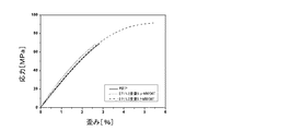
図2は、エポキシマトリックスおよびナノ複合材料についての典型的な引張応力−歪み曲線を示す。純エポキシ樹脂およびp−MWCNT充填エポキシ複合材料はいずれも、脆性な状態で破壊され、明らかな歪みは検出されないが、f−MWCNT充填エポキシ複合材料は、やや延性挙動を示す。MWCNTの強化作用をより理解するために、ヤングの弾性率、引張強度および破断点伸びにおける相対的向上(規格化値)を図3に示す。概して、f−MWCNTは、p−MWCNTと比べて強化エポキシ樹脂中ではるかにより効率的である。破断点伸びの約82%の増加が、1重量%のf−MWCNT充填にて得られる。図3は、調査試料のKICおよびGICにおける相対的向上(規格化値)を示す。p−MWCNTおよびf−MWCNTはいずれも顕著にエポキシ樹脂を強化する。f−MWCNTは、p−MWCNTに比べてはるかにより効率的にエポキシ樹脂を強化する。GICの約110%の増加が1重量%のf−MWCNTの組み込みにより得られる。これは、エポキシおよびf−MWCNT間の良好な界面接着によるものである。 FIG. 2 shows a typical tensile stress-strain curve for an epoxy matrix and a nanocomposite. Both the pure epoxy resin and the p-MWCNT filled epoxy composite material are broken in a brittle state, and no obvious strain is detected, but the f-MWCNT filled epoxy composite material exhibits a slightly ductile behavior. In order to better understand the strengthening action of MWCNT, the relative improvement (normalized value) in Young's modulus, tensile strength and elongation at break is shown in FIG. In general, f-MWCNT is much more efficient in reinforced epoxy resins compared to p-MWCNT. An about 82% increase in elongation at break is obtained with 1 wt% f-MWCNT loading. FIG. 3 shows the relative improvement (normalized value) in the K IC and G IC of the survey samples. Both p-MWCNT and f-MWCNT significantly reinforce the epoxy resin. f-MWCNT reinforces the epoxy resin much more efficiently than p-MWCNT. An approximately 110% increase in GIC is obtained by incorporating 1% by weight of f-MWCNT. This is due to good interfacial adhesion between epoxy and f-MWCNT.
Claims (12)
該カーボンナノチューブが、以下の工程:
a)カーボンナノチューブを反応ゾーン中へ設置する工程、
b)オゾン、酸素および水の混合物を前記カーボンナノチューブへ通過させる工程
を含む酸素/オゾンによる気相中での同時処理により酸化されていることを特徴とする、複合材料。 Comprising an epoxy polymer, carbon nanotubes and optionally a curing agent;
The carbon nanotube has the following steps:
a) installing a carbon nanotube into the reaction zone;
b) A composite material characterized by being oxidized by simultaneous treatment in the gas phase with oxygen / ozone including a step of passing a mixture of ozone, oxygen and water through the carbon nanotubes.
Applications Claiming Priority (3)
| Application Number | Priority Date | Filing Date | Title |
|---|---|---|---|
| EP09003652A EP2228406A1 (en) | 2009-03-13 | 2009-03-13 | Improved mechanical properties of epoxy filled with functionalized carbon nanotubes |
| EP09003652.6 | 2009-03-13 | ||
| PCT/EP2010/001226 WO2010102732A1 (en) | 2009-03-13 | 2010-02-27 | Improved mechanical properties of epoxy filled with functionalized carbon nanotubes |
Publications (2)
| Publication Number | Publication Date |
|---|---|
| JP2012520351A true JP2012520351A (en) | 2012-09-06 |
| JP2012520351A5 JP2012520351A5 (en) | 2013-04-11 |
Family
ID=40677630
Family Applications (1)
| Application Number | Title | Priority Date | Filing Date |
|---|---|---|---|
| JP2011553319A Withdrawn JP2012520351A (en) | 2009-03-13 | 2010-02-27 | Improved mechanical properties of epoxies filled with functionalized carbon nanotubes |
Country Status (7)
| Country | Link |
|---|---|
| US (1) | US20120123020A1 (en) |
| EP (2) | EP2228406A1 (en) |
| JP (1) | JP2012520351A (en) |
| KR (1) | KR20110138349A (en) |
| CN (1) | CN102348758A (en) |
| TW (1) | TW201105718A (en) |
| WO (1) | WO2010102732A1 (en) |
Cited By (1)
| Publication number | Priority date | Publication date | Assignee | Title |
|---|---|---|---|---|
| KR20200086123A (en) * | 2019-01-08 | 2020-07-16 | 인하대학교 산학협력단 | Basalt fiber reinforced epoxy composites reinforced with ozone treated single-walled carbon nanotubes and method for manufacturing the same |
Families Citing this family (15)
| Publication number | Priority date | Publication date | Assignee | Title |
|---|---|---|---|---|
| US9085678B2 (en) | 2010-01-08 | 2015-07-21 | King Abdulaziz City For Science And Technology | Clean flame retardant compositions with carbon nano tube for enhancing mechanical properties for insulation of wire and cable |
| EP2479215A1 (en) * | 2011-01-25 | 2012-07-25 | Bayer MaterialScience AG | Method for making a composite material |
| US10023702B2 (en) | 2011-09-02 | 2018-07-17 | Bae Systems Plc | Curable monomers |
| US8871019B2 (en) | 2011-11-01 | 2014-10-28 | King Abdulaziz City Science And Technology | Composition for construction materials manufacturing and the method of its production |
| CN102604129B (en) * | 2012-03-11 | 2013-12-11 | 东华大学 | Dispersion method of carbon nanometer pipe in ethoxyline resin |
| CN103374207B (en) * | 2012-04-18 | 2017-04-19 | 国家纳米科学中心 | Epoxy composite material and preparation method thereof |
| CN103131293A (en) * | 2012-11-13 | 2013-06-05 | 高润宝 | Preparation method of carbon nano tube modified heat-resistant wave-transparent coating used for aircraft |
| CN103059514B (en) * | 2012-12-05 | 2015-05-20 | 哈尔滨工业大学 | Preparation method of magnetic lyophoby type carbon nano tube base nanochannel damping plate and damper |
| KR101481263B1 (en) * | 2013-04-29 | 2015-01-13 | 전북대학교산학협력단 | Silica-graphene oxide complex, Compositon of that and High strength plastic resin containing that |
| WO2019002907A1 (en) * | 2017-06-26 | 2019-01-03 | Nano-Tech S.P.A. | Polymeric compositions loaded with carbon nanotubes, their production and use |
| CN110256815B (en) * | 2019-06-25 | 2022-03-25 | 山东大展纳米材料有限公司 | Toughened conductive epoxy resin composite material and preparation method thereof |
| KR102214478B1 (en) * | 2019-09-09 | 2021-02-09 | 인하대학교 산학협력단 | Carbon fiber-reinforced epoxy composites with ozone-treated carbon blacks and manufacturing method. |
| KR102404145B1 (en) * | 2020-07-14 | 2022-06-02 | 인하대학교 산학협력단 | Basalt fiber-reinforced epoxy composites with graphene oxide and method for manufacturing the same |
| CN111825952B (en) * | 2020-07-14 | 2023-02-10 | 国家纳米科学中心 | Super-ordered carbon nanotube epoxy resin composite material and preparation method and application thereof |
| CN115538170B (en) * | 2022-09-06 | 2023-10-13 | 长春工业大学 | Modified carbon fiber, preparation method and application thereof, and modified carbon fiber epoxy resin composite material |
Family Cites Families (16)
| Publication number | Priority date | Publication date | Assignee | Title |
|---|---|---|---|---|
| GB1469930A (en) | 1974-10-11 | 1977-04-06 | Atomic Energy Authority Uk | Carbon filaments |
| CA1175616A (en) | 1981-01-05 | 1984-10-09 | Exxon Research And Engineering Company | Production of iron monoxide and carbon filaments therefrom |
| US4663230A (en) | 1984-12-06 | 1987-05-05 | Hyperion Catalysis International, Inc. | Carbon fibrils, method for producing same and compositions containing same |
| US7588699B2 (en) | 2001-11-02 | 2009-09-15 | The United States Of America As Represented By The Administrator Of The National Aeronautics And Space Administration | Electrically conductive, optically transparent polymer/carbon nanotube composites and process for preparation thereof |
| CA2507831C (en) | 2002-11-27 | 2010-06-01 | William Marsh Rice University | Functionalized carbon nanotube-polymer composites and interactions with radiation |
| EP2368932B1 (en) | 2003-06-16 | 2014-01-15 | William Marsh Rice University | Fabrication of carbon nanotube reinforced polymer composites |
| CA2530471A1 (en) | 2003-06-23 | 2005-02-17 | William Marsh Rice University | Elastomers reinforced with carbon nanotubes |
| JP5328150B2 (en) | 2004-08-02 | 2013-10-30 | ユニバーシティー オブ ヒューストン | Carbon nanotube reinforced polymer nanocomposite |
| CN101189373A (en) * | 2004-10-22 | 2008-05-28 | 海珀里昂催化国际有限公司 | Improved ozonolysis of carbon nanotubes |
| DE102004054959A1 (en) | 2004-11-13 | 2006-05-18 | Bayer Technology Services Gmbh | Catalyst for producing carbon nanotubes by decomposition of gaseous carbon compounds on a heterogeneous catalyst |
| DE102006007147A1 (en) | 2006-02-16 | 2007-08-23 | Bayer Technology Services Gmbh | Process for the continuous production of catalysts |
| US20070276077A1 (en) | 2006-04-05 | 2007-11-29 | Nano-Proprietary, Inc. | Composites |
| US20080090951A1 (en) | 2006-03-31 | 2008-04-17 | Nano-Proprietary, Inc. | Dispersion by Microfluidic Process |
| KR20090025194A (en) | 2006-03-31 | 2009-03-10 | 어플라이드 나노테크 홀딩스, 인크. | Carbon nanotube-reinforced nanocomposites |
| EP2066743B1 (en) | 2006-09-04 | 2021-12-15 | Oy Morphona Ltd. | Functionalized cellulose - carbon nanotube nanocomposites |
| WO2008054034A1 (en) | 2006-10-31 | 2008-05-08 | Korea Research Institute Of Chemical Technology | Method for manufacturing epoxy nanocomposite material containing vapor-grown carbon nanofibers and its products thereby |
-
2009
- 2009-03-13 EP EP09003652A patent/EP2228406A1/en not_active Withdrawn
-
2010
- 2010-02-27 EP EP10707460A patent/EP2406317A1/en not_active Withdrawn
- 2010-02-27 WO PCT/EP2010/001226 patent/WO2010102732A1/en active Application Filing
- 2010-02-27 KR KR1020117020967A patent/KR20110138349A/en not_active Application Discontinuation
- 2010-02-27 CN CN2010800116154A patent/CN102348758A/en active Pending
- 2010-02-27 JP JP2011553319A patent/JP2012520351A/en not_active Withdrawn
- 2010-02-27 US US13/256,243 patent/US20120123020A1/en not_active Abandoned
- 2010-03-12 TW TW099107183A patent/TW201105718A/en unknown
Cited By (2)
| Publication number | Priority date | Publication date | Assignee | Title |
|---|---|---|---|---|
| KR20200086123A (en) * | 2019-01-08 | 2020-07-16 | 인하대학교 산학협력단 | Basalt fiber reinforced epoxy composites reinforced with ozone treated single-walled carbon nanotubes and method for manufacturing the same |
| KR102185383B1 (en) * | 2019-01-08 | 2020-12-01 | 인하대학교 산학협력단 | Basalt fiber reinforced epoxy composites reinforced with ozone treated single-walled carbon nanotubes and method for manufacturing the same |
Also Published As
| Publication number | Publication date |
|---|---|
| TW201105718A (en) | 2011-02-16 |
| CN102348758A (en) | 2012-02-08 |
| EP2228406A1 (en) | 2010-09-15 |
| WO2010102732A1 (en) | 2010-09-16 |
| KR20110138349A (en) | 2011-12-27 |
| EP2406317A1 (en) | 2012-01-18 |
| US20120123020A1 (en) | 2012-05-17 |
Similar Documents
| Publication | Publication Date | Title |
|---|---|---|
| JP2012520351A (en) | Improved mechanical properties of epoxies filled with functionalized carbon nanotubes | |
| Wei et al. | Influence of graphene oxide with different oxidation levels on the properties of epoxy composites | |
| Zhang et al. | Dispersion stability of functionalized MWCNT in the epoxy–amine system and its effects on mechanical and interfacial properties of carbon fiber composites | |
| Ma et al. | Development of polymer composites using modified, high-structural integrity graphene platelets | |
| Wan et al. | Grafting of epoxy chains onto graphene oxide for epoxy composites with improved mechanical and thermal properties | |
| Alam et al. | Surface amination of carbon nanoparticles for modification of epoxy resins: plasma-treatment vs. wet-chemistry approach | |
| Advani | Processing and properties of nanocomposites | |
| JP6490580B2 (en) | Composite materials with very low content of carbon-based nanofillers, methods for their preparation and their use | |
| Scaffaro et al. | Plasma Functionalization of Multiwalled Carbon Nanotubes and Their Use in the Preparation of Nylon 6‐Based Nanohybrids | |
| Wu et al. | Synthesis, characterization, and electrical properties of polypyrrole/multiwalled carbon nanotube composites | |
| Hong et al. | Effects of oxidative conditions on properties of multi-walled carbon nanotubes in polymer nanocomposites | |
| Kesavan Pillai et al. | Epoxy-based carbon nanotubes reinforced composites | |
| Maio et al. | Statistical Study of the Influence of CNTs Purification and Plasma Functionalization on the Properties of Polycarbonate‐CNTs Nanocomposites | |
| KR20110131203A (en) | Water vapour assisted ozonolysis of carbon nanotubes | |
| EP1877482A1 (en) | Carbon nanotube reinforced thermoplastic polymer composites achieved through benzoyl peroxide initiated interfacial bonding to polymer matrices | |
| JP5477702B2 (en) | Boron nitride nanotube derivative, dispersion thereof, and method for producing boron nitride nanotube derivative | |
| Yang et al. | Realizing the full nanofiller enhancement in melt-spun fibers of poly (vinylidene fluoride)/carbon nanotube composites | |
| Wang et al. | Application of carbon nanotubes from waste plastics as filler to epoxy resin composite | |
| Kleinschmidt et al. | Functionalized-carbon nanotubes with physisorbed ionic liquid as filler for epoxy nanocomposites | |
| Wu et al. | One step fabrication of multi-walled carbon nanotubes/graphene nanoplatelets hybrid materials with excellent mechanical property | |
| Dumas et al. | Polybenzoxazine nanocomposites: case study of carbon nanotubes | |
| Zhang et al. | Preparation and characterization of alkylated carbon nanotube/polyimide nanocomposites | |
| Nath et al. | Growth mechanism of carbon nanotubes produced by pyrolysis of a composite film of poly (vinyl alcohol) and fly ash | |
| John et al. | Plasma functionalized CNT/Cyanate ester nanocomposites for aerospace structural applications | |
| Mou'ad et al. | Characterization and morphology of modified multi-walled carbon nanotubes filled thermoplastic natural rubber (TPNR) composite |
Legal Events
| Date | Code | Title | Description |
|---|---|---|---|
| A521 | Request for written amendment filed |
Free format text: JAPANESE INTERMEDIATE CODE: A523 Effective date: 20130225 |
|
| A621 | Written request for application examination |
Free format text: JAPANESE INTERMEDIATE CODE: A621 Effective date: 20130225 |
|
| A761 | Written withdrawal of application |
Free format text: JAPANESE INTERMEDIATE CODE: A761 Effective date: 20130501 |