JP2012152096A - Kinetic efficiency determination device - Google Patents
Kinetic efficiency determination device Download PDFInfo
- Publication number
- JP2012152096A JP2012152096A JP2011239445A JP2011239445A JP2012152096A JP 2012152096 A JP2012152096 A JP 2012152096A JP 2011239445 A JP2011239445 A JP 2011239445A JP 2011239445 A JP2011239445 A JP 2011239445A JP 2012152096 A JP2012152096 A JP 2012152096A
- Authority
- JP
- Japan
- Prior art keywords
- vehicle
- energy
- detecting
- consumption rate
- energy consumption
- Prior art date
- Legal status (The legal status is an assumption and is not a legal conclusion. Google has not performed a legal analysis and makes no representation as to the accuracy of the status listed.)
- Pending
Links
Images


Classifications
-
- Y—GENERAL TAGGING OF NEW TECHNOLOGICAL DEVELOPMENTS; GENERAL TAGGING OF CROSS-SECTIONAL TECHNOLOGIES SPANNING OVER SEVERAL SECTIONS OF THE IPC; TECHNICAL SUBJECTS COVERED BY FORMER USPC CROSS-REFERENCE ART COLLECTIONS [XRACs] AND DIGESTS
- Y02—TECHNOLOGIES OR APPLICATIONS FOR MITIGATION OR ADAPTATION AGAINST CLIMATE CHANGE
- Y02T—CLIMATE CHANGE MITIGATION TECHNOLOGIES RELATED TO TRANSPORTATION
- Y02T10/00—Road transport of goods or passengers
- Y02T10/80—Technologies aiming to reduce greenhouse gasses emissions common to all road transportation technologies
- Y02T10/84—Data processing systems or methods, management, administration
Abstract
Description
この発明は、車両の運動効率を的確に判定する運動効率判定装置に関する。 The present invention relates to an exercise efficiency determination device that accurately determines the exercise efficiency of a vehicle.
従来から、車両の運転者等のユーザに対して、省燃費運転支援に供する指標の提供を行う技術が開示されている。 2. Description of the Related Art Conventionally, a technique for providing an index for use in fuel-saving driving support to a user such as a vehicle driver has been disclosed.
特許文献1には、内燃機関車両(以下、エンジン車両という。)の省燃費運転支援に供する指標として、次の(1)式に示す実効燃費MPGeffが提案されている。
MPGeff=Vavg×D×Δt×ΔHr/(Ef−ΔEke−ΔEpe)
…(1)
MPGeff = Vavg × D × Δt × ΔHr / (Ef−ΔEke−ΔEpe)
... (1)
(1)式において、運動エネルギ変化ΔEkeは、次の(2)式で算出される。
ΔEke=(1/2)×m×(Vi−Vi-1)2 …(2)
In the equation (1), the kinetic energy change ΔEke is calculated by the following equation (2).
ΔEke = (1/2) × m × (Vi−Vi−1) 2 (2)
(1)式において、位置エネルギ変化ΔEpeは、次の(3)式で算出される。
ΔEpe=m×g×(Hi−Hi-1) …(3)
In the equation (1), the potential energy change ΔEpe is calculated by the following equation (3).
ΔEpe = m × g × (Hi−Hi−1) (3)
上記(1)〜(3)式において、Δtは所定時間(単位時間)、Vavgは所定時間Δt当たりの平均速度、Dはガソリンの密度で例えば0.72[g/cc]、ΔHrは燃焼過程における燃料の反応エンタルピーであって例えば43[kJ/gm]、Efは燃焼エネルギ(化学エネルギ)、mは車両の質量、(Vi−Vi-1)は所定時間Δt間の車速Vの変化、gは重力加速度、(Hi−Hi-1)は所定時間Δt間の位置(高さ)の変化である。 In the above equations (1) to (3), Δt is a predetermined time (unit time), Vavg is an average speed per predetermined time Δt, D is a gasoline density, for example, 0.72 [g / cc], and ΔHr is a combustion process. For example, 43 [kJ / gm], Ef is the combustion energy (chemical energy), m is the mass of the vehicle, (Vi-Vi-1) is the change in the vehicle speed V during the predetermined time Δt, g Is the gravitational acceleration, and (Hi-Hi-1) is the change in position (height) during a predetermined time Δt.
(1)式で示される実効燃費MPGeff(運動効率の指標)により、加減速時や登坂時、降坂時といった状況下でもエネルギ利用度の評価が可能となる。 The energy consumption can be evaluated even under conditions such as acceleration / deceleration, uphill, downhill, etc., by the effective fuel consumption MPGeff (index of motion efficiency) expressed by equation (1).
しかしながら、近時、提案乃至市販されている電動車両(以下、EV車両という。)、ハイブリッド車両(以下、HEV車両という。)、又はプラグインハイブリッド車両(以下、PHEV車両という。)においては、上記(1)式のエンジン車両に係る実効燃費MPGeffでは、対応しないケースが発生することをこの出願の発明者が突き止めた。 However, recently, in the electric vehicles (hereinafter referred to as EV vehicles), hybrid vehicles (hereinafter referred to as HEV vehicles), or plug-in hybrid vehicles (hereinafter referred to as PHEV vehicles) that are proposed or marketed. In the effective fuel consumption MPGeff related to the engine vehicle of formula (1), the inventor of this application has found that a case that does not correspond occurs.
例えば、HEV車両が、エンジン燃焼を停止して電気エネルギのみで傾斜ゼロ度の道路を定速走行している場合には、実効燃費MPGeffの分母の3つの項が全てゼロ値(Ef=0、ΔEke=0、ΔEpe=0)となるため、実効燃費MPGeffの値の算出が不能(MPGeff→∞)になってしまう。 For example, if the HEV vehicle is running at a constant speed on a road with zero inclination only by electric energy with engine combustion stopped, all three terms of the denominator of the effective fuel consumption MPGeff are all zero values (Ef = 0, Since ΔEke = 0 and ΔEpe = 0), the value of the effective fuel consumption MPGeff cannot be calculated (MPGeff → ∞).
この発明は、このような課題を考慮してなされたものであり、エンジン車両、EV車両、HEV車両、又はPHEV車両において車両の運動効率を的確に判定することを可能とする運動効率判定装置を提供することを目的とする。 The present invention has been made in consideration of such a problem, and provides a motion efficiency determination device that can accurately determine the motion efficiency of a vehicle in an engine vehicle, an EV vehicle, an HEV vehicle, or a PHEV vehicle. The purpose is to provide.
この発明に係る運動効率判定装置は、車両の運動効率を求める運動効率判定装置であって、前記車両の速度を検出する車速検出手段と、前記車両が走行する道路の高度を検出する高度検出手段と、走行用モータの消費電力を検出する電力検出手段と、前記車両の質量と前記車速検出手段により検出された車速とに応じて運動エネルギを算出する運動エネルギ算出手段と、前記高度検出手段により検出された高度に応じて位置エネルギを算出する位置エネルギ算出手段と、前記電力検出手段により検出された消費電力に応じて電気エネルギを算出する電気エネルギ算出手段と、エネルギ消費率算出手段と、を備え、前記エネルギ消費率算出手段は、前記運動エネルギと前記位置エネルギと前記電気エネルギとにより前記車両のエネルギ消費率を求めることを特徴とする。 The motion efficiency determination device according to the present invention is a motion efficiency determination device for determining the motion efficiency of a vehicle, the vehicle speed detection means detecting the speed of the vehicle, and the altitude detection means detecting the altitude of the road on which the vehicle travels. Power detection means for detecting the power consumption of the motor for driving, kinetic energy calculation means for calculating kinetic energy according to the mass of the vehicle and the vehicle speed detected by the vehicle speed detection means, and the altitude detection means A potential energy calculating means for calculating potential energy according to the detected altitude; an electric energy calculating means for calculating electric energy according to the power consumption detected by the power detecting means; and an energy consumption rate calculating means. And the energy consumption rate calculating means calculates the energy consumption rate of the vehicle by the kinetic energy, the potential energy, and the electric energy. And wherein the Mel.
この発明によれば、EV車両におけるEV走行時のエネルギ消費率(単位距離当たりのエネルギ消費量)を、運動エネルギの増減、位置エネルギの増減の他、電気エネルギの増減をも考慮して算出するようにしたので、EV車両、HEV車両及びPHEV車両のEV走行時においても車両の運動効率を的確に判定することができる。 According to the present invention, the energy consumption rate (energy consumption per unit distance) during EV traveling in an EV vehicle is calculated in consideration of increase / decrease in kinetic energy, increase / decrease in potential energy, and increase / decrease in electrical energy. Since it did in this way, the exercise | movement efficiency of a vehicle can be determined accurately also at the time of EV driving | running | working of EV vehicle, HEV vehicle, and PHEV vehicle.
この場合、さらに、燃料噴射量を検出する燃料噴射量検出手段と、前記燃料噴射量検出手段により検出された燃料噴射量に応じて燃焼エネルギを算出する燃焼エネルギ算出手段と、を設け、前記エネルギ消費率算出手段は、前記運動エネルギと前記位置エネルギと前記電気エネルギとに、前記燃焼エネルギを加えたエネルギにより前記車両のエネルギ消費率を求めることを特徴とする。 In this case, a fuel injection amount detecting means for detecting the fuel injection amount and a combustion energy calculating means for calculating combustion energy according to the fuel injection amount detected by the fuel injection amount detecting means are provided, and the energy The consumption rate calculating means obtains an energy consumption rate of the vehicle from energy obtained by adding the combustion energy to the kinetic energy, the potential energy, and the electric energy.
この発明によれば、エンジン車両、HEV車両又はPHEV車両において車両の運動効率の指標としてのエネルギ消費率を算出することができる。 According to the present invention, it is possible to calculate an energy consumption rate as an index of vehicle movement efficiency in an engine vehicle, HEV vehicle, or PHEV vehicle.
なお、前記エネルギ消費率は、前記車両が走行中である場合は前記燃焼エネルギと前記運動エネルギと前記位置エネルギと前記電気エネルギとを合計した値を走行距離検出手段により検出された走行距離で除算することにより算出し、前記車両が停止中である場合は前記燃焼エネルギと前記電気エネルギとを合計した値を停止時間で除算することにより算出することを特徴とする。 When the vehicle is running, the energy consumption rate is obtained by dividing the sum of the combustion energy, the kinetic energy, the position energy, and the electric energy by the travel distance detected by the travel distance detection means. And when the vehicle is stopped, the vehicle energy is calculated by dividing the sum of the combustion energy and the electric energy by the stop time.
この発明によれば、走行中と停止中とで最適な計算方法により、HEV車両又はPHEV車両における車両の運動効率の指標としてのエネルギ消費率を算出することができる。 According to the present invention, it is possible to calculate the energy consumption rate as an index of the motion efficiency of the vehicle in the HEV vehicle or the PHEV vehicle by an optimal calculation method for running and stopping.
なお、車両が停止したと判断したときに燃料の噴射を停止してアイドルストップ制御を行うHEV車両又はPHEV車両では、前記車両が停止中である場合、エネルギ消費率を、前記電気エネルギの値を前記停止時間で除算することにより算出するようにすればよい。 In the HEV vehicle or PHEV vehicle that performs idle stop control by stopping fuel injection when it is determined that the vehicle has stopped, when the vehicle is stopped, the energy consumption rate is set to the electric energy value. What is necessary is just to calculate by dividing by the said stop time.
また、前記高度検出手段は、高度センサを用いる他に、道路勾配検出手段で検出した道路勾配と走行距離検出手段により検出した走行距離とに応じて道路の高度を検出するようにすることもできる。 In addition to using an altitude sensor, the altitude detecting means can detect the altitude of the road according to the road gradient detected by the road gradient detecting means and the travel distance detected by the travel distance detecting means. .
前記道路勾配を検出する道路勾配検出手段としては、傾斜センサ(勾配センサ)自体ではなく、ブレーキ液圧と車両の加速度に基づいて検出することができる。ブレーキ液圧と車両の加速度に基づいて道路勾配を検出することにより、ブレーキ操作中においても、前記運動エネルギのエネルギ消費分を反映したエネルギ消費率を適切に算出することができる。 The road gradient detecting means for detecting the road gradient can be detected not based on the inclination sensor (gradient sensor) itself but based on the brake fluid pressure and the acceleration of the vehicle. By detecting the road gradient based on the brake fluid pressure and the vehicle acceleration, the energy consumption rate reflecting the energy consumption of the kinetic energy can be appropriately calculated even during the braking operation.
なお、車両の質量は、車両本体の質量+運転者の質量(設定値)としてもよいが、より正確には、車両本体の質量に、運転者を含む乗員の質量と荷物の質量とを加算した値となることに鑑み、サスストロークセンサの出力値の質量換算値(乗員の質量+荷物の質量)に前記車両本体の質量を加算した値(補正質量)とすることが好ましい。 The mass of the vehicle may be the mass of the vehicle main body + the mass of the driver (set value), but more precisely, the mass of the vehicle body and the mass of the passenger and the luggage are added to the mass of the vehicle main body. In view of the above, it is preferable to set a value (corrected mass) obtained by adding the mass of the vehicle body to the mass converted value of the output value of the suspension stroke sensor (occupant mass + luggage mass).
この発明によれば、EV車両、HEV車両、又はPHEV車両において車両の運動効率の指標としてのエネルギ消費率を算出することで、車両の運動効率を的確に判定することができる。また、走行中と停止中とで最適な計算方向によってエネルギ消費率を算出することができる。 According to this invention, by calculating the energy consumption rate as an index of the vehicle's movement efficiency in the EV vehicle, HEV vehicle, or PHEV vehicle, it is possible to accurately determine the vehicle's movement efficiency. In addition, the energy consumption rate can be calculated in an optimal calculation direction during traveling and when stopped.
また、走行中と停止中とで最適な計算方法により、HEV車両又はPHEV車両において車両の運動効率の指標としてのエネルギ消費率を算出することができる。 Further, the energy consumption rate as an index of the vehicle's motion efficiency can be calculated in an HEV vehicle or PHEV vehicle by an optimal calculation method during traveling and when stopped.
以下、この発明に係る運動効率判定装置について、これが搭載された車両との関係において好適な実施形態を挙げ、添付の図面を参照して説明する。 DESCRIPTION OF EMBODIMENTS Hereinafter, an exercise efficiency determination device according to the present invention will be described with reference to the accompanying drawings by giving preferred embodiments in relation to a vehicle equipped with the exercise efficiency determination device.
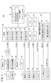
図1は、この実施形態に係る運動効率判定装置が搭載されたHEV車両(以下、単に車両ともいう。)10の概略構成を示すブロック図である。 FIG. 1 is a block diagram showing a schematic configuration of an HEV vehicle (hereinafter also simply referred to as a vehicle) 10 in which the exercise efficiency determination device according to this embodiment is mounted.
HEV車両10は、動力源としてエンジン12と、走行用モータ14とを備える。エンジン12あるいは走行用モータ14の出力軸に発生する動力が図示しないトランスミッション等を介し、車軸を通じて車輪に伝達されることで、HEV車両10が走行する。
The HEV
エンジン12の燃焼は、FI−ECU(Fuel Injection - Electronic Control Unit)16による制御下に、燃料タンク18に接続される燃料噴射装置20からエンジンに噴射される燃料噴射量cf[cc]で調整される。
The combustion of the
燃料噴射量cf[cc]は、FI−ECU16からメータECU22に供給される。
The fuel injection amount cf [cc] is supplied from the FI-
走行用モータ14は、力行時には、車載のバッテリ(蓄電装置)24からインバータ等の電力変換装置26を通じて交流駆動信号を受け前記出力軸が回転する。また、回生時には、走行用モータ14が発電機として機能し、走行用モータ14に発生した電力により電力変換装置26を通じてバッテリ24が充電される。
During power running, the traveling
バッテリ24と電力変換装置26との間には電力センサ28が挿入され、電力センサ28により計測された消費電力(充電電力も含む。)P[W]がメータECU22に供給される。
A
高度センサ30は、高度(海抜)h[m]を検出してメータECU22に供給する。高度センサ30は、図示しないナビゲーション装置に含まれるGPS受信装置での受信高さ情報に代替することができる。
The
傾斜センサ32は、車両10の走行方向の傾斜角である道路勾配θ[゜]を検出してメータECU22に供給する。道路勾配θ[゜]は、傾斜センサ32の他に、車両に搭載される3軸加速度センサ(不図示)のピッチング方向(車両の前後方向)の出力の積分値として求めることもできる。
The
車速センサ34は、車速V[m/s]をメータECU22に供給する。
The
距離センサ36は、トリップ走行距離等の走行距離d[m]をメータECU22に供給する。なお、走行距離d[m]は、距離センサ36に代替して測位装置と地図情報とを備えるナビゲーション装置(不図示)の走行距離情報により求めることもできる。
The
メインスイッチ38は、車両10のイグニッション信号Ig(Ig=オン又はオフ)をメータECU22に供給する。
The
メータECU22には、さらに、運転者等のユーザの利便に供される、車両10のダッシュボード等に配置されるマルチインフォメーションディスプレイ(複数情報表示装置、以下、単に、ディスプレイという。)40が接続される。
The
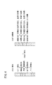
この実施形態において、ディスプレイ40には、それぞれ、省エネルギ運転支援指標(経済的運転支援指標)としてのecoガイド(省エネルギガイド)42と運動効率に対応するエネルギ消費率Ecj[kJ/m]とが表示される。なお、燃費[km/L]を表示させることもできる。
In this embodiment, the
ディスプレイ40に表示するとともに、あるいはディスプレイ40に代替して、ナビゲーション装置用のディスプレイの全画面、あるいは一部画面にecoガイド42及び・又はエネルギ消費率Ecjを表示するようにしてもよい。
The
エネルギ消費率Ecj[kJ/m]についてのecoガイド42は、この実施形態では、緑色のバー44の長さで表示され、エネルギ消費率Ecjが低い程、バーの長さが長くされる。エネルギ消費率Ecjが低い程、いわゆる省エネルギ運転度が高く、エネルギ消費率Ecjを閾値と比較して、閾値よりも小さい値である場合には、バーを緑色で表示し、大きい値である場合には、バーを赤色で表示するようにして、省エネルギ運転の程度に応じて種々変更することができる。
In this embodiment, the
メータECU22は、マイクロコンピュータを含む計算機であり、CPU(中央処理装置)46、メモリ(記憶部)48であるROM(EEPROMも含む。)、RAM(ランダムアクセスメモリ)、その他、A/D変換器、D/A変換器等の入出力装置(I/O)50、計時部としてのタイマ51等を有しており、CPU46がROMに記録されているプログラムを読み出し実行することで各種機能実現手段として機能する。
The
この実施形態において、メータECU22(以下、単にECU22ともいう。)は、運動エネルギ算出手段(Ei算出手段)52、位置エネルギ算出手段(Ep算出手段)54、電気エネルギ算出手段(Eb算出手段)56、燃焼エネルギ算出手段(Ef算出手段)58、及びエネルギ消費率算出手段(Ecj算出手段)60等として機能する。 In this embodiment, the meter ECU 22 (hereinafter also simply referred to as the ECU 22) includes a kinetic energy calculating means (Ei calculating means) 52, a potential energy calculating means (Ep calculating means) 54, and an electric energy calculating means (Eb calculating means) 56. , Combustion energy calculation means (Ef calculation means) 58, energy consumption rate calculation means (Ecj calculation means) 60, and the like.
次に、上記実施形態の動作について、メモリ48に記憶されたプログラムに対応する図2に示す概略フローチャートを参照しながら説明する。
Next, the operation of the above embodiment will be described with reference to the schematic flowchart shown in FIG. 2 corresponding to the program stored in the
ステップS1において、ECU22(のCPU46)は、メインスイッチ38がオン状態になっているか否かをイグニッション信号Igのオンオフにより判定する。
In step S1, the ECU 22 (or the CPU 46) determines whether or not the
イグニッション信号Igがオン状態になっている場合には、ステップS2において、ECU22は、タイマ51により所定時間、例えば0.1秒間計時する。
If the ignition signal Ig is in the on state, the
タイマ51による所定時間の経過を検出したとき、ステップS3において、ECU22は、次に説明する物理量をメモリ48に取り込む。なお、物理量取り込み処理の1回目では、所定時間間のエネルギ消費量Es[kJ]を算出することはできないので、ここでは、2回目以降の取り込み処理であるものとして説明する。
When the elapse of the predetermined time by the
そのステップS3において、ECU22は、FI−ECU16から燃料噴射量cf[cc]を、電力センサ28から消費電力(又は充電電力)P[W]を、高度センサ30から高さh[m]を、車速センサ34から車速V[m/s]を、距離センサ36から走行距離d[m]を、それぞれメモリ48に取り込む(記憶する)。
In step S3, the
このステップS3において、ECU22は、メモリ48に取り込んだ物理量を、それぞれ、燃料噴射量cf[cc]は、所定時間間(サンプリング時間であり経過時間tという。)の値に、消費電力P[W]は、経過時間tの値に、高さh[m]は、経過時間tの高度差の値に、車速V[m/s]は、経過時間tの平均値に、走行距離d[m]は、経過時間tの走行距離に、それぞれ変換する。以下で使用される値は、この変換値であるものとする。なお、実際上、経過時間tは、上記タイマ51により計時される所定時間であり、好ましくは、上記0.1秒間隔で計算されたエネルギ消費率を複数回分記憶して求められる平均値を出力するようにするとecoガイド42のバー44の長さ表示の変化が滑らかになる。
In this step S3, the
高さh[m]の変化分は、高度センサ30によらずに、傾斜センサ32で検出された道路勾配θ[゜]と前記経過時間tの間の走行距離d[m]と、から次の(1)式で求めることもできる。
h[m]=d・sinθ …(1)
The amount of change in the height h [m] is determined from the road gradient θ [°] detected by the
h [m] = d · sin θ (1)
次いで、ステップS4において、ECU22は、車両10が走行中であるか否かを車速V[m/s]により判定する。車速V[m/s]がゼロ値である場合には、走行中ではなく停車中と判定し、車速V[m/s]が有限値(非ゼロ値)である場合には、走行中と判定する。
Next, in step S4, the
走行中と判定したとき、ステップS5において、ECU22は、車両10の走行中のエネルギ消費量Ea[kJ]を次の(2)式により算出する。
Ea[kJ]=Ef+Eb+Ei+Ep …(2)
When it is determined that the vehicle is traveling, in step S5, the
Ea [kJ] = Ef + Eb + Ei + Ep (2)
ここで、Efは燃焼エネルギ、Ebは電気エネルギ、Eiは運動エネルギ、Epは位置エネルギであり、それぞれ、次の(3)〜(6)式で求めることができる。 Here, Ef is combustion energy, Eb is electrical energy, Ei is kinetic energy, and Ep is potential energy, which can be obtained by the following equations (3) to (6), respectively.
Ef[kJ]=cf・e・η …(3)
ここで、cf[cc]は、燃料噴射量、e[kJ/cc]は、燃料の熱価であり、例えば、普通ガソリンであれば、e=35[kJ/cc]の固定値。ηは、エンジン12の熱効率であり、この実施形態では、η=0.33(車両10によって異なる)を使用している。
Ef [kJ] = cf · e · η (3)
Here, cf [cc] is the fuel injection amount, and e [kJ / cc] is the heat value of the fuel. For example, in the case of ordinary gasoline, e = 35 [kJ / cc] is a fixed value. η is the thermal efficiency of the
Eb[kJ]=P・t/0.278 …(4)
ここで、P[W]は、電力、t[h]は上述した経過時間tの時間換算値、すなわち、2.77×10⁻⁵[h]≒0.1[s]である。
Eb [kJ] = P · t / 0.278 (4)
Here, P [W] is power, and t [h] is a time-converted value of the above-described elapsed time t, that is, 2.77 × 10 −5 [h] ≈0.1 [s].
Ei[kJ]=m(V1−V0)2/2 …(5)
ここで、m[kg]は、車両10の質量(重量センサ等を用いて運転者等乗員の質量を車重に加えた値であることがより好ましい。)、V1、V0[m/s]は、車速であり、経過時間t(計算周期)間の今回車速V1と前回車速V0を示す。
Ei [kJ] = m (V1 -V0) 2/2 ... (5)
Here, m [kg] is the mass of the vehicle 10 (more preferably a value obtained by adding the mass of a passenger such as a driver to the vehicle weight using a weight sensor or the like), V1, V0 [m / s]. Is the vehicle speed and indicates the current vehicle speed V1 and the previous vehicle speed V0 during the elapsed time t (calculation cycle).
Ep=m・g・(h1−h0)=m・g・d・sinθ …(6)
ここで、m[kg]は、質量、g[m/s2]は、重力加速度、h1、h0[km]は、高さであり、経過時間t(計算周期)間の今回高さh1と前回高さh0を示す。d[km]は、経過時間t間の走行距離、θ[゜]は、道路勾配である。
Ep = m · g · (h1−h0) = m · g · d · sin θ (6)
Here, m [kg] is mass, g [m / s 2 ] is gravitational acceleration, h1, h0 [km] is height, and this height h1 between elapsed time t (calculation cycle) and Indicates the previous height h0. d [km] is the travel distance during the elapsed time t, and θ [°] is the road gradient.
次いで、ステップS6において、ECU22は、車両10の単位距離当たりのエネルギ消費量であるエネルギ消費率Ecj[kJ/m]を次の(7)式により算出する。
Ecj[kJ/m]=Ea/d=(Ef+Eb+Ei+Ep)/d …(7)
Next, in step S6, the
Ecj [kJ / m] = Ea / d = (Ef + Eb + Ei + Ep) / d (7)
ここで、d[km]は、経過時間t間の走行距離であり、上述したように、Ea[kJ]は、エネルギ消費量、Efは、燃焼エネルギ、Ebは、電気エネルギ、Eiは、運動エネルギ、Epは、位置エネルギである。なお、エネルギ消費率Ecjは、値が小さい程、単位距離当たりのエネルギ消費量が少なくなるので、より経済的な運転をしていると言える。 Here, d [km] is the travel distance during the elapsed time t. As described above, Ea [kJ] is energy consumption, Ef is combustion energy, Eb is electrical energy, and Ei is motion. Energy, Ep is potential energy. In addition, it can be said that the energy consumption rate Ecj is operating more economically because the energy consumption per unit distance decreases as the value decreases.
この場合、ECU22は、燃焼エネルギEfが、燃料噴射により消費されるので正の値のみをとるようにする。電気エネルギEbは、放電(消費)されるときには正の値を取るようにし、回生充電されるときには負の値を取るようにする。また、運動エネルギEiは、加速時にはエネルギが蓄えられるので、負の値とし、減速時にはエネルギが消費されるので、正の値を取るようにする。さらに、位置エネルギEpは、登坂方向でエネルギが蓄えられるので、負の値とし、降坂方向でエネルギが消費されるので、正の値とする。EV車両及びPHEV車両では、電気エネルギEbが消費方向で正の値となる点に留意する。
In this case, the
このように、この実施形態では、図4に示すように、EV車両、HEV車両10及びPHEV車両のエネルギ損失である、エンジン損失、機械伝達損失、電気・補機損失、走行伝達損失、及びブレーキ熱損失等の損失のトータル損失(総和)を抑制することによりエコ運転に直結することに着目した。しかし、走行中にこれらの値を算出することはきわめて困難であることを考慮し、鋭意考究の結果、これらのエネルギ損失のトータルエネルギ損失が、エネルギ保存の法則により、運動エネルギEiの消費量、位置エネルギEpの消費量、電気エネルギEbの消費量、及び燃焼エネルギEfの消費量のトータル(総和)のエネルギ消費量に等しいことに着目した。
Thus, in this embodiment, as shown in FIG. 4, the energy loss of EV vehicle,
そこで、走行中のエネルギ消費量を測定することで、時々刻々エネルギ消費量を算出し、エネルギ消費率Ecjとして表示するようにし、運転者がこのエネルギ消費率Ecjが小さく(低く)なるように運転することで、燃費・電費を向上させることができるとの考えに至った。 Therefore, by measuring the energy consumption during traveling, the energy consumption is calculated every moment and displayed as the energy consumption rate Ecj, and the driver operates so that the energy consumption rate Ecj is small (low). This led to the idea that fuel economy and electricity consumption could be improved.
これらの考究に基づき、ステップS7において、ECU22は、算出したエネルギ消費率Ecjを、図1のディスプレイ40の囲いの中の表示内容に示すように表示する。
Based on these considerations, in step S7, the
なお、表示されるエネルギ消費率Ecjの単位は、[kJ/m]としているが、これには限定されず、入力装置(不図示)の操作により、単位切替手段としても動作するECU22は、例えば、次の(8)式及び(9)式に示すように、エネルギ消費率Ecm[km/L](いわゆる燃費)(図3A参照)又はエネルギ消費率Ecw[Wh/m](いわゆる電費の逆数)(図3B参照)と、簡単な演算に基づき、単位を切り替えて表示することができる。エネルギ消費率Ecj[kJ/m]、エネルギ消費率Ecm[km/L]、及びエネルギ消費率Ecw[Wh/m]のうち、少なくとも2つを交互に又は同時に表示するように設定を変更することもできる。
Ecm[km/L]=d/(Ef+Eb+Ei+Ep)/η/e
=1/Ecj/η/e …(8)
Ecw[Wh/m]=0.278(Ef+Eb+Ei+Ep)/d
=0.278Ecj …(9)
The unit of the energy consumption rate Ecj to be displayed is [kJ / m]. However, the unit is not limited to this, and the
Ecm [km / L] = d / (Ef + Eb + Ei + Ep) / η / e
= 1 / Ecj / η / e (8)
Ecw [Wh / m] = 0.278 (Ef + Eb + Ei + Ep) / d
= 0.278 Ecj (9)
図3Aのエネルギ消費率Ecm[km/L](いわゆる燃費)の表示の場合には、ecoガイド42のバー44の長さは、燃費が悪くなる(低くなる)ほど短くなり、図3Bのエネルギ消費率Ecw[Wh/m](いわゆる電費の逆数)の表示の場合には、ecoガイド42のバー44の長さは、電費の逆数が小さくなるほど短くなる点に留意する。
In the case of the display of the energy consumption rate Ecm [km / L] (so-called fuel consumption) in FIG. 3A, the length of the
なお、上述したステップS4において、ECU22は、車両10が停止していると判定した場合、運動エネルギEiはゼロ値となるので、ステップS8に示すように、車両が停車中のエネルギ消費量Eas[kJ]を次の(10)式又は(11)式により算出する。
Eas[kJ]=Ef+Eb(いわゆるアイドルストップ制御がない場合。)
…(10)
Eas[kJ]=Eb(いわゆるアイドルストップ制御を行っている場合。)
…(11)
In step S4 described above, when the
Eas [kJ] = Ef + Eb (when there is no so-called idle stop control)
(10)
Eas [kJ] = Eb (when so-called idle stop control is performed)
... (11)
なお、アイドルストップ制御は、例えば、車速VがV=0[km/h]でフットブレーキを踏んでいることを、FI−ECU16が検出したときに、燃料噴射装置20によるエンジン12に対する燃料噴射の停止を行う制御をいう。この停止制御がECU22により検出される。
In the idle stop control, for example, when the FI-
そして、車両10が停止していると判定した場合、ステップS9に示すように、ECU22は、単位距離当たりのエネルギ消費量であるエネルギ消費率Ecj[kJ/m]ではなく、次の(12)式及び(13)式に示すように、単位時間当たりのエネルギ消費量であるエネルギ消費率Ecs[kJ/min]を算出して表示するようにしてもよい。
Ecs[kJ/min]=(Ef+Eb)/t(いわゆるアイドルストップ制御をしない場合。) …(12)
Ecs[kJ/min]=Eb/t(いわゆるアイドルストップ制御をしている場合。) …(13)
And when it determines with the
Ecs [kJ / min] = (Ef + Eb) / t (when so-called idle stop control is not performed) (12)
Ecs [kJ / min] = Eb / t (when so-called idle stop control is performed) (13)
(12)、(13)式において、tは、停車中の経過時間(停車時間)であるが、停車中に所定周期毎に計算するための単位時間としても良い。 In Expressions (12) and (13), t is an elapsed time (stop time) while the vehicle is stopped, but may be a unit time for calculating every predetermined period while the vehicle is stopped.
以上説明したように上述した実施形態に係る車両10の運動効率を求める運動効率判定装置を搭載したHEV車両10は、燃料噴射量cf[cc]を検出する燃料噴射量検出手段としての燃料噴射装置20と、車両10の速度V[m/s]を検出する車速検出手段としての車速センサ34と、車両10の高さh[km]を検出する高度検出手段としての高度センサ30と、走行用モータ14の消費電力P[W]を検出する電力検出手段としての電力センサ28と、車両10の走行距離d[m]を検出する走行距離検出手段としての距離センサ36と、燃料噴射装置20により検出された燃料噴射量cf[cc]に応じて燃焼エネルギEf[kJ]を算出するEf算出手段58と、車両10の質量m[kg]と車速センサ34により検出された車速V[m/s]とに応じて運動エネルギEiを算出するEi算出手段52と、車両の高さh[km]に応じて位置エネルギEpを算出するEp算出手段54と、電力センサ28により検出された消費電力P[W]に応じて電気エネルギEbを算出するEb算出手段56と、エネルギ消費率Ecjを算出するEcj算出手段60と、を備え、Ecj算出手段60は、燃焼エネルギEfと運動エネルギEiと位置エネルギEpと電気エネルギEbとにより車両10のエネルギ消費率Ecjを上記(7)式により求めるように構成している。
As described above, the
この実施形態によれば、HEV車両10におけるEV走行時のエネルギ消費率Ecj[kJ/m]を、運動エネルギEiの増減、位置エネルギEpの増減の他、電気エネルギEbの増減をも考慮して算出するようにしたので、HEV車両10の他、EV車両又はPHEV車両のEV走行時において車両の運動効率を的確に判定することができる。
According to this embodiment, the energy consumption rate Ecj [kJ / m] at the time of EV traveling in the
また、この実施形態によれば、車両の高度差を求めるため、高度センサ30の代わりに、傾斜センサ32と距離センサ36との両方を使用することを記載しているが、傾斜センサ32の代わりにエンジントルクと車速Vの変化に基づいて勾配を求めても良い。これにより、傾斜センサ32が不要となるため、部品点数の削減をすることができる。
Further, according to this embodiment, it is described that both the
また、走行距離dを求めるために、距離センサ36を使用しているが、車速センサ34に検出された車速Vと走行時間tとによって走行距離dを求めることとしても良い(d=V・t)。これにより、距離センサ36が不要となるため、部品点数を削減することができる。
Further, although the
また、走行中では、単位走行距離当たりのエネルギ消費量であるエネルギ消費率Ecj[kJ/m]を算出し、停止中では、単位時間当たりのエネルギ消費量であるエネルギ消費率Ecs[kJ/min]を算出して表示することで、走行中と停止中とで最適な計算方法により、HEV車両10又はPHEV車両において車両の運動効率の指標を算出することができる。
Further, an energy consumption rate Ecj [kJ / m] that is an energy consumption amount per unit travel distance is calculated during traveling, and an energy consumption rate Ecs [kJ / min] that is an energy consumption amount per unit time during stoppage. ] Can be calculated and displayed on the
この実施形態によれば、車両10の運転者等のユーザに対して省燃費運転支援に供する的確な指標が提供される。
According to this embodiment, an accurate index for providing fuel-saving driving support to a user such as a driver of the
なお、この発明は、上述の実施形態に限らず、この明細書の記載内容に基づき、種々の構成を採り得ることはもちろんである。 Note that the present invention is not limited to the above-described embodiment, and it is needless to say that various configurations can be adopted based on the contents described in this specification.
例えば、図5は、傾斜センサ32に代替して、HEV車両10A等の車両に搭載されているブレーキ液圧センサ62を利用し、さらに、車両の質量m[kg](ここでは、車両本体の質量)を補正した実質量m[kg]{車両本体の質量に乗員の質量と荷物の質量を加算して補正した実際の質量(補正質量ともいう。)}を算出するためにサスストロークセンサ64を利用した他の実施形態に係る運動効率装置が搭載されたHEV車両10Aの構成を示している。なお、サスストロークセンサ64は、ヘッドライトの自動光軸調整用等に搭載されているものを利用することができる。
For example, FIG. 5 uses a brake
ブレーキ液圧センサ62は、公知のように、運転者のフットブレーキのペダルの操作量(踏込量)に応じて、油圧制御機構、ブレーキアクチュエータを通じて車輪に制動力が付与される際の、前記油圧制御機構の油圧をブレーキ液圧B[kPa]として検出する。
As is well known, the brake
また、サスストロークセンサ64は、公知のように、フロントサスペンションとリアサスペンションにそれぞれ設けられ、フロント荷重の印加とリア荷重の印加によるフロントサスペンション及びリアサスペンションの各ショックアブソーバ(ダンパー)の伸縮量の変化量(ストローク変化量)S[m]を、電圧変化量等として検出する。
Further, as is well known, the
まず、ブレーキ液圧センサ62で検出されるブレーキ液圧B[kPa]から道路勾配θ[゜]を算出する仕方について説明する。なお、ここでは、道路勾配θ[゜]を正接tanθ=Slope(単位は、[%]とする。)として算出する。
First, a method for calculating the road gradient θ [°] from the brake fluid pressure B [kPa] detected by the brake
シミュレーション乃至実験確認により、ブレーキ液圧B[kPa]と加速度α[m/s2]とが比例関係にあることが分かった。すなわち、ブレーキ液圧B[kPa]の増加に比例して加速度α[m/s2](減速加速度)が増加する。比例定数は負であるが、車種により比例定数の値の大きさが異なる値となる。 From simulation or experimental confirmation, it was found that the brake fluid pressure B [kPa] and the acceleration α [m / s 2 ] are in a proportional relationship. That is, the acceleration α [m / s 2 ] (deceleration acceleration) increases in proportion to the increase in the brake fluid pressure B [kPa]. Although the proportionality constant is negative, the value of the proportionality constant varies depending on the vehicle type.
図6は、或る車種の車両、ここでは、HEV車両10Aのブレーキ液圧Bと加速度αとの関係を示す特性図である。
FIG. 6 is a characteristic diagram showing the relationship between the brake fluid pressure B and the acceleration α of a vehicle of a certain vehicle type, here
点線の特性100は、平坦路(Slope=0[%])でのブレーキ液圧Bと加速度αとの関係を示しており、平坦路での加速度αを、αfとすると、特性100は、次の(14)式に当てはめられる。 A dotted line characteristic 100 indicates a relationship between the brake hydraulic pressure B and the acceleration α on a flat road (Slope = 0 [%]). When the acceleration α on the flat road is αf, the characteristic 100 is expressed as follows. (14).
αf=−{(α0−α1)/B1}B−α0 …(14)
ここで、α0は、B=0のときのオフセット値、α1は、B=B1のときの加速度αである。
αf = − {(α0−α1) / B1} B−α0 (14)
Here, α0 is an offset value when B = 0, and α1 is an acceleration α when B = B1.
特性102は、下り勾配で道路勾配Slopeが既知の負の値、特性104は、上り勾配で道路勾配Slopeが既知の正の値、特性106は、上り勾配で道路勾配Slopeが既知の正の値であって、特性104の道路勾配Slopeより急な勾配である。特性100、特性102、特性104、及び特性106は、B=0のときのオフセット値のみが異なる右下がりの平行な傾斜を有する点に留意する。 The characteristic 102 is a negative value with a known road slope Slope on a downward slope, the characteristic 104 is a positive value with an upward slope known with the road slope Slope, and the characteristic 106 is a positive value with an upward slope known with the road slope Slope. Further, the slope is steeper than the road slope Slope of the characteristic 104. Note that characteristic 100, characteristic 102, characteristic 104, and characteristic 106 have parallel slopes with a downward slope that differ only in the offset value when B = 0.
これらの特性100、102、104、106(いずれも、道路勾配Slopeは既知である。)から、道路勾配(単位勾配)1[%]当たりの加速度(基準加速度)αrを求めた。
From these
この実施形態では、同一値のブレーキ液圧Bにおいて、道路勾配Slopeが1[%]増加すると、加速度(減速加速度)αが、αr=−0.1[m/s2]増加することが求められた。 In this embodiment, when the road gradient Slope increases by 1 [%] at the same brake fluid pressure B, the acceleration (deceleration acceleration) α is required to increase by αr = −0.1 [m / s 2 ]. It was.
よって、任意の道路勾配Slopeは、次の(15)式で算出することができる。
Slope=Δα×1[%]/αr …(15)
Therefore, an arbitrary road gradient Slope can be calculated by the following equation (15).
Slope = Δα × 1 [%] / αr (15)
ここで、Δαは、求めようとする道路勾配Slopeでの、ブレーキ液圧B(測定値)に対する加速度α(測定値)と平坦路での加速度αfとの差を示している。すなわち、Δαは、次の(16)式で算出することができる。
Δα=α−αf
=α−[−{(α0−α1)/B1}B−α0]
=α+{(α0−α1)/B1}B+α0 …(16)
Here, Δα indicates the difference between the acceleration α (measured value) with respect to the brake fluid pressure B (measured value) and the acceleration αf on a flat road at the road gradient Slope to be obtained. That is, Δα can be calculated by the following equation (16).
Δα = α−αf
= Α-[-{(α0-α1) / B1} B-α0]
= Α + {(α0−α1) / B1} B + α0 (16)
この(16)式を(15)式に代入することにより、道路勾配Slopeは、次の(17)式で求められることが分かる。
Slope=[α+{(α0−α1)/B1}B+α0]/αr …(17)
By substituting the equation (16) into the equation (15), it is understood that the road gradient Slope is obtained by the following equation (17).
Slope = [α + {(α0−α1) / B1} B + α0] / αr (17)
(17)式中、変数である加速度αは、車速センサ34で測定した車速V[m/s]から車両加速度算出手段68により公知の処理により求めることができる。この場合、経過時間t(計算周期)間での車速Vsの変化率を求めればよい。すなわち、経過時間t(計算周期)間の今回車速V1と前回車速V0から、次の(18)式で求めることができる。
α=(V1−V0)/t …(18)
In the equation (17), the variable acceleration α can be obtained by a known process by the vehicle acceleration calculating means 68 from the vehicle speed V [m / s] measured by the
α = (V1−V0) / t (18)
よって、道路勾配算出手段66は、それぞれが変数である、ブレーキ液圧センサ62で測定したブレーキ液圧B[kPa]と、車速センサ34で測定した車速V[m/s]に基づき求めた加速度αとを(17)式に代入することにより道路勾配Slopeを求めることができる。
Therefore, the road gradient calculation means 66 is an acceleration determined based on the brake fluid pressure B [kPa] measured by the brake
(17)式で求めた道路勾配Slope[%]を、道路勾配θ[゜]に変換することで、(6)式により位置エネルギEpを求めることができる。 By converting the road gradient Slope [%] obtained by the equation (17) into the road gradient θ [°], the potential energy Ep can be obtained by the equation (6).
よって、図5に示した他の実施形態によれば、フットブレーキの操作中においても、位置エネルギEpを求めるのに必要な道路勾配θ[゜]を推定することができる。すなわち、フットブレーキの操作中においても、位置エネルギEpの変動分を考慮した(7)式に示したエネルギ消費率Ecj[kJ/m]の算出が可能となる。 Therefore, according to another embodiment shown in FIG. 5, it is possible to estimate the road gradient θ [°] necessary for obtaining the potential energy Ep even during the operation of the foot brake. That is, even during the operation of the foot brake, the energy consumption rate Ecj [kJ / m] shown in the equation (7) in consideration of the fluctuation of the potential energy Ep can be calculated.
次に、サスストロークセンサ64を利用した車両の質量{ここでは、車両本体の質量m(以下、meという。)、いわゆる空車状態の質量meに対して、乗員+荷物の質量m1を加算して補正した実際の質量(補正質量ともいう。)、以下、理解の便宜のために補正質量m[kg]という。}の補正質量算出手段70による算出の仕方について説明する。 Next, the mass of the vehicle using the suspension stroke sensor 64 (here, the mass m of the vehicle body (hereinafter referred to as me), the so-called empty mass me) is added to the mass m1 of the occupant + the luggage. The corrected actual mass (also referred to as corrected mass) is hereinafter referred to as corrected mass m [kg] for convenience of understanding. }, The method of calculation by the corrected mass calculation means 70 will be described.
補正出量mは、空車状態の質量meに乗員+荷物の質量m1を加算した次の(19)式で求めることができる。
m=me+m1 …(19)
The corrected output amount m can be obtained by the following equation (19) in which the occupant + load mass m1 is added to the empty state mass me.
m = me + m1 (19)
ここで、乗員+荷物の質量m1は、フロントサスペンションに掛けられる荷重の変化分と、リアサスペンションに掛けられる荷重の変化分の合計値であることから、フロントのサスストロークセンサ64(64f)のフロントセンサ出力Vsf[V]とフロント荷重Wf[kg]との関係(特性)、及びリアのサスストロークセンサ64(64r)のリアセンサ出力Vsr[V]と、リア荷重Wr[kg]との関係(特性)を予め測定しておくことで、フロントセンサ出力Vsf及びリアセンサ出力Vsrを検出することで、任意の(乗員+荷物)の質量m1を求めることができる。 Here, the mass m1 of the occupant + luggage is the total value of the change in the load applied to the front suspension and the change in the load applied to the rear suspension, so the front suspension stroke sensor 64 (64f) has a front. Relationship (characteristic) between the sensor output Vsf [V] and the front load Wf [kg], and relationship (characteristic) between the rear sensor output Vsr [V] of the rear suspension stroke sensor 64 (64r) and the rear load Wr [kg]. ) In advance, the front sensor output Vsf and the rear sensor output Vsr can be detected, so that an arbitrary (occupant + luggage) mass m1 can be obtained.
図7は、静止時に測定したフロント荷重Wfとフロントセンサ出力Vsfとの関係に対応する特性112と特性114を示し、さらに、特性112と特性114を近似した相関近似式の特性110を示している。 FIG. 7 shows a characteristic 112 and a characteristic 114 corresponding to the relationship between the front load Wf measured at rest and the front sensor output Vsf, and further shows a characteristic 110 of a correlation approximation formula that approximates the characteristic 112 and the characteristic 114. .
フロントシート上に物を載せた(荷重を掛けていく)ときの右上がりの矢印で示すフロントセンサ出力Vsfの特性112と、物を降ろした(荷重を減らしていく)ときの左下がりの矢印で示すフロントセンサ出力Vsfの特性114では、ヒステリシスがあるが、このヒステリシスは、フロントサスペンションのフリクションを原因として発生する。 A characteristic 112 of the front sensor output Vsf indicated by a right-up arrow when an object is placed on the front seat (applying a load) and a left-down arrow when the object is lowered (load is reduced) In the characteristic 114 of the front sensor output Vsf shown, there is hysteresis, but this hysteresis occurs due to the friction of the front suspension.
特性110の直線で示すフロント荷重Wfの相関近似式、すなわち前記特性110の1次式は、Vsf=(特性110の直線の傾き)×Wf+Vsf0={(Vfs1−Vsf0)/Wf1}×Wf+Vsf0を、Wfで解いた次の(20)式で表すことができる。
Wf={Wf1/(Vsf1−Vsf0)}(Vsf−Vsf0)…(20)
The correlation approximate expression of the front load Wf indicated by the straight line of the characteristic 110, that is, the linear expression of the characteristic 110 is Vsf = (inclination of the straight line of the characteristic 110) × Wf + Vsf0 = {(Vfs1−Vsf0) / Wf1} × Wf + Vsf0. It can be expressed by the following equation (20) solved by Wf.
Wf = {Wf1 / (Vsf1-Vsf0)} (Vsf-Vsf0) (20)
ここで、Wf1は、フロントシート上に載せた重量物の既知の荷重、Vsf0、Vsf1は、その荷重Wf1の前記重量物をフロントシートに載せなかったとき(Vsf0:オフセット値)と載せたとき(Vsf1)のそれぞれのフロントセンサ出力Vsfの読取値である。なお、(20)式中、{Wf1/(Vsf1−Vsf0)}は、1[V]当たりのフロント荷重Wfの変化量を表している。 Here, Wf1 is a known load of a heavy article placed on the front seat, and Vsf0, Vsf1 are the same as when the heavy article with the load Wf1 is not placed on the front seat (Vsf0: offset value) ( Vsf1) is a read value of each front sensor output Vsf. In the equation (20), {Wf1 / (Vsf1-Vsf0)} represents a change amount of the front load Wf per 1 [V].
図8は、静止時に測定したリア荷重Wrとリアセンサ出力Vsrとの関係に対応する特性122と特性124を示し、さらに、特性122と特性124を近似した相関近似式の特性120を示している。 FIG. 8 shows a characteristic 122 and a characteristic 124 corresponding to the relationship between the rear load Wr measured at rest and the rear sensor output Vsr, and further shows a characteristic 120 of a correlation approximate expression in which the characteristic 122 and the characteristic 124 are approximated.
リアシート上に物を載せた(荷重を掛けていく)ときのリアセンサ出力Vsrの特性122と、物を降ろした(荷重を減らしていく)ときのリアセンサ出力Vsrの特性124は、略同等である。 The characteristic 122 of the rear sensor output Vsr when an object is placed on the rear seat (applying a load) and the characteristic 124 of the rear sensor output Vsr when the object is lowered (decreasing the load) are substantially the same.
リア荷重Wrの相関近似式は、(20)式と同様にして、次の(21)式で表すことができる。
Wr=−{Wr1/(Vsr1−Vsr0)}(Vsr−Vsr0)
…(21)
The correlation approximate expression of the rear load Wr can be expressed by the following expression (21) in the same manner as the expression (20).
Wr =-{Wr1 / (Vsr1-Vsr0)} (Vsr-Vsr0)
... (21)
ここで、−{Wr1/(Vsr1−Vsr0)}は、1[V]当たりのリア荷重Wrの変化量、Vsr0は、リア荷重Wr=0の場合のリアセンサ出力Vsr=Vsr0、Vsr1は、リア荷重Wr=Wr1(既知)の場合のリアセンサ出力Vsr=Vsr1である。なお、リアセンサ出力Vsrは、フロントセンサ出力Vsfと逆傾斜になっているが、単に、サスストロークセンサ64rの出力として、荷重が増加するほど電圧が減少するセンサを使用しているに過ぎなく、傾斜を逆にすれば、右上がりの特性を得ることができる。
Here, − {Wr1 / (Vsr1−Vsr0)} is the amount of change in the rear load Wr per 1 [V], Vsr0 is the rear sensor output Vsr = Vsr0 and Vsr1 is the rear load when the rear load Wr = 0. The rear sensor output Vsr = Vsr1 when Wr = Wr1 (known). Although the rear sensor output Vsr has an inverse slope with respect to the front sensor output Vsf, the output of the
よって、(19)式は、次の(22)式に変形でき、補正質量mは、フロントセンサ出力Vsfとリアセンサ出力Vfrを検出し、(22)式に代入することで求めることができる。 Therefore, the equation (19) can be transformed into the following equation (22), and the correction mass m can be obtained by detecting the front sensor output Vsf and the rear sensor output Vfr and substituting them into the equation (22).
m=me+m1
=me+Wf+Wr
=me+{Wf1/(Vsf1−Vsf0)}(Vsf−Vsf0)
−{Wr1/(Vsr1−Vsr0)}(Vsr−Vsr0) …(22)
なお、(22)式で求めた補正質量mを、(5)式に代入することにより運動エネルギEiを、また、(6)式に代入することにより位置エネルギEpを、積載量に応じてより正確に算出することができる。
m = me + m1
= Me + Wf + Wr
= Me + {Wf1 / (Vsf1-Vsf0)} (Vsf-Vsf0)
-{Wr1 / (Vsr1-Vsr0)} (Vsr-Vsr0) (22)
It should be noted that the kinetic energy Ei is substituted by substituting the corrected mass m obtained by the equation (22) into the equation (5), and the potential energy Ep is substituted according to the load amount by substituting into the equation (6). It can be calculated accurately.
従って、図5に示した実施形態によれば、(7)式に示したエネルギ消費率Ecj[kJ/m]のより正確な値での算出が可能となる。 Therefore, according to the embodiment shown in FIG. 5, it is possible to calculate the energy consumption rate Ecj [kJ / m] shown in the equation (7) with a more accurate value.
10、10A…HEV車両 12…エンジン
14…走行用モータ 18…燃料タンク
20…燃料噴射装置 22…メータECU(ECU)
24…バッテリ 28…電力センサ
30…高度センサ 32…傾斜センサ
34…車速センサ 36…距離センサ
40…マルチインフォメーションディスプレイ(ディスプレイ)
52…運動エネルギ算出手段(Ei算出手段)
54…位置エネルギ算出手段(Ep算出手段)
56…電気エネルギ算出手段(Eb算出手段)
58…燃焼エネルギ算出手段(Ef算出手段)
60…エネルギ消費率算出手段(Ecj算出手段)
62…ブレーキ液圧センサ
64(64f、64r)…サスストロークセンサ
66…道路勾配算出手段 68…車両加速度算出手段
70…補正質量算出手段
DESCRIPTION OF
24 ...
52 ... Kinetic energy calculation means (Ei calculation means)
54... Position energy calculation means (Ep calculation means)
56: Electric energy calculation means (Eb calculation means)
58 ... Combustion energy calculation means (Ef calculation means)
60: Energy consumption rate calculating means (Ecj calculating means)
62 ... brake hydraulic pressure sensor 64 (64f, 64r) ...
Claims (8)
前記車両の速度を検出する車速検出手段と、
前記車両が走行する道路の高度を検出する高度検出手段と、
走行用モータの消費電力を検出する電力検出手段と、
前記車両の質量と前記車速検出手段により検出された車速とに応じて運動エネルギを算出する運動エネルギ算出手段と、
前記高度検出手段により検出された高度に応じて位置エネルギを算出する位置エネルギ算出手段と、
前記電力検出手段により検出された消費電力に応じて電気エネルギを算出する電気エネルギ算出手段と、
エネルギ消費率算出手段と、を備え、
前記エネルギ消費率算出手段は、
前記運動エネルギと前記位置エネルギと前記電気エネルギとにより前記車両のエネルギ消費率を求める
ことを特徴とする運動効率判定装置。 A motion efficiency determination device for determining the motion efficiency of a vehicle,
Vehicle speed detection means for detecting the speed of the vehicle;
Altitude detecting means for detecting the altitude of the road on which the vehicle travels;
Power detection means for detecting the power consumption of the traveling motor;
Kinetic energy calculating means for calculating kinetic energy according to the mass of the vehicle and the vehicle speed detected by the vehicle speed detecting means;
Positional energy calculation means for calculating potential energy according to the height detected by the height detection means;
Electrical energy calculation means for calculating electrical energy according to the power consumption detected by the power detection means;
Energy consumption rate calculating means,
The energy consumption rate calculating means includes:
An kinetic efficiency determination apparatus, wherein an energy consumption rate of the vehicle is obtained from the kinetic energy, the potential energy, and the electric energy.
さらに、
燃料噴射量を検出する燃料噴射量検出手段と、
前記燃料噴射量検出手段により検出された燃料噴射量に応じて燃焼エネルギを算出する燃焼エネルギ算出手段と、を設け、
前記エネルギ消費率算出手段は、
前記運動エネルギと前記位置エネルギと前記電気エネルギとに、前記燃焼エネルギを加えたエネルギにより前記車両のエネルギ消費率を求めることを特徴とする運動効率判定装置。 The exercise efficiency determination device according to claim 1,
further,
Fuel injection amount detection means for detecting the fuel injection amount;
Combustion energy calculation means for calculating combustion energy according to the fuel injection amount detected by the fuel injection amount detection means,
The energy consumption rate calculating means includes:
An kinetic efficiency determination apparatus characterized in that an energy consumption rate of the vehicle is obtained from energy obtained by adding the combustion energy to the kinetic energy, the potential energy, and the electric energy.
さらに、
前記車両の走行距離を検出する走行距離検出手段を設け、
前記エネルギ消費率は、前記車両が走行中である場合は前記燃焼エネルギと前記運動エネルギと前記位置エネルギと前記電気エネルギとを合計した値を前記走行距離検出手段により検出された走行距離で除算することにより算出し、前記車両が停止中である場合は前記燃焼エネルギと前記電気エネルギとを合計した値を停止時間で除算することにより算出する
ことを特徴とする運動効率判定装置。 In the exercise efficiency determination device according to claim 2,
further,
Providing travel distance detection means for detecting the travel distance of the vehicle,
When the vehicle is traveling, the energy consumption rate is obtained by dividing the sum of the combustion energy, the kinetic energy, the positional energy, and the electrical energy by the traveling distance detected by the traveling distance detecting means. When the vehicle is stopped, the motion efficiency determination device is calculated by dividing the sum of the combustion energy and the electric energy by the stop time.
前記車両が停止中である場合に、アイドルストップ制御を行っているときには、エネルギ消費率を、前記電気エネルギの値を前記停止時間で除算することにより算出する
ことを特徴とする運動効率判定装置。 The apparatus for measuring exercise efficiency according to claim 3.
When the vehicle is stopped, when performing idle stop control, the energy consumption rate is calculated by dividing the electric energy value by the stop time.
前記エネルギ消費率は、前記車両が走行中である場合は前記運動エネルギと前記位置エネルギと前記電気エネルギとを合計した値を前記走行距離検出手段により検出された走行距離で除算することにより算出し、前記車両が停止中である場合は前記電気エネルギの値を停止時間で除算することにより算出する
ことを特徴とする運動効率判定装置。 The exercise efficiency determination device according to claim 1,
When the vehicle is running, the energy consumption rate is calculated by dividing the sum of the kinetic energy, the positional energy, and the electrical energy by the travel distance detected by the travel distance detection means. When the vehicle is stopped, the value of the electric energy is calculated by dividing by the stop time.
前記高度検出手段は、前記車両が走行する道路の道路勾配を検出する道路勾配検出手段と、前記車両の走行距離を検出する走行距離検出手段と、を有するものであり、前記道路勾配と、前記道路勾配を走行した前記走行距離とに応じて前記車両が走行する道路の高度を検出する
ことを特徴とする運動効率判定装置。 In any one of Claims 1-3, or the exercise efficiency determination apparatus of Claim 5,
The altitude detection means includes road gradient detection means for detecting a road gradient of a road on which the vehicle travels, and travel distance detection means for detecting a travel distance of the vehicle, and the road gradient; An exercise efficiency determination apparatus, wherein an altitude of a road on which the vehicle travels is detected according to the travel distance traveled on a road gradient.
前記車両のブレーキ作動時のブレーキ液圧を検出するブレーキ液圧検出手段と、
前記車両の加速度を検出する車両加速度検出手段と、を更に備え、
前記道路勾配検出手段は前記ブレーキ液圧と前記加速度に基づいて前記道路勾配を検出する
ことを特徴とする運動効率判定装置。 The exercise efficiency determination device according to claim 6,
Brake fluid pressure detecting means for detecting a brake fluid pressure at the time of braking operation of the vehicle;
Vehicle acceleration detecting means for detecting the acceleration of the vehicle,
The road efficiency detecting device detects the road gradient based on the brake fluid pressure and the acceleration.
前記車両の上下移動を検出するサスストロークセンサを更に備え、
前記運動エネルギもしくは位置エネルギは少なくとも前記車両の質量に応じて求められるものであり、前記車両の質量は、車両本体の質量と、前記車両への積載量と、前記サスストロークセンサの出力値とによって求める
ことを特徴とする運動効率判定装置。 In the exercise efficiency determination device according to any one of claims 1 to 7,
A suspension stroke sensor for detecting vertical movement of the vehicle;
The kinetic energy or potential energy is determined at least according to the mass of the vehicle, and the mass of the vehicle is determined by the mass of the vehicle body, the load on the vehicle, and the output value of the suspension stroke sensor. A motion efficiency determination device characterized by being obtained.
Priority Applications (1)
| Application Number | Priority Date | Filing Date | Title |
|---|---|---|---|
| JP2011239445A JP2012152096A (en) | 2010-12-27 | 2011-10-31 | Kinetic efficiency determination device |
Applications Claiming Priority (3)
| Application Number | Priority Date | Filing Date | Title |
|---|---|---|---|
| JP2010289294 | 2010-12-27 | ||
| JP2010289294 | 2010-12-27 | ||
| JP2011239445A JP2012152096A (en) | 2010-12-27 | 2011-10-31 | Kinetic efficiency determination device |
Publications (1)
| Publication Number | Publication Date |
|---|---|
| JP2012152096A true JP2012152096A (en) | 2012-08-09 |
Family
ID=46793796
Family Applications (1)
| Application Number | Title | Priority Date | Filing Date |
|---|---|---|---|
| JP2011239445A Pending JP2012152096A (en) | 2010-12-27 | 2011-10-31 | Kinetic efficiency determination device |
Country Status (1)
| Country | Link |
|---|---|
| JP (1) | JP2012152096A (en) |
Cited By (4)
| Publication number | Priority date | Publication date | Assignee | Title |
|---|---|---|---|---|
| JP2015211527A (en) * | 2014-04-25 | 2015-11-24 | 株式会社豊田自動織機 | Industrial vehicle |
| CN105984389A (en) * | 2015-03-19 | 2016-10-05 | 丰田自动车株式会社 | Vehicle |
| CN108645630A (en) * | 2018-06-27 | 2018-10-12 | 奇瑞万达贵州客车股份有限公司 | A kind of plug-in hybrid passenger car road energy consumption testing device and test method |
| CN113525154A (en) * | 2020-04-21 | 2021-10-22 | 丰田自动车北美公司 | Influence of load on transportation energy |
Citations (6)
| Publication number | Priority date | Publication date | Assignee | Title |
|---|---|---|---|---|
| JPH0241111U (en) * | 1988-09-13 | 1990-03-22 | ||
| JP2002084603A (en) * | 2000-06-20 | 2002-03-22 | Bae Systems Controls Inc | Energy control system for hybrid electric rolling stock |
| JP2007120334A (en) * | 2005-10-25 | 2007-05-17 | Denso Corp | Abnormality diagnostic device of vehicle driving system |
| JP2007283882A (en) * | 2006-04-14 | 2007-11-01 | Toyota Motor Corp | Road slope estimating device |
| JP2008197076A (en) * | 2007-02-09 | 2008-08-28 | Masaji Sasaki | Method and device for displaying fuel consumption |
| JP2009001059A (en) * | 2007-06-19 | 2009-01-08 | Isuzu Motors Ltd | Travel support information provision system |
-
2011
- 2011-10-31 JP JP2011239445A patent/JP2012152096A/en active Pending
Patent Citations (6)
| Publication number | Priority date | Publication date | Assignee | Title |
|---|---|---|---|---|
| JPH0241111U (en) * | 1988-09-13 | 1990-03-22 | ||
| JP2002084603A (en) * | 2000-06-20 | 2002-03-22 | Bae Systems Controls Inc | Energy control system for hybrid electric rolling stock |
| JP2007120334A (en) * | 2005-10-25 | 2007-05-17 | Denso Corp | Abnormality diagnostic device of vehicle driving system |
| JP2007283882A (en) * | 2006-04-14 | 2007-11-01 | Toyota Motor Corp | Road slope estimating device |
| JP2008197076A (en) * | 2007-02-09 | 2008-08-28 | Masaji Sasaki | Method and device for displaying fuel consumption |
| JP2009001059A (en) * | 2007-06-19 | 2009-01-08 | Isuzu Motors Ltd | Travel support information provision system |
Cited By (9)
| Publication number | Priority date | Publication date | Assignee | Title |
|---|---|---|---|---|
| JP2015211527A (en) * | 2014-04-25 | 2015-11-24 | 株式会社豊田自動織機 | Industrial vehicle |
| CN105984389A (en) * | 2015-03-19 | 2016-10-05 | 丰田自动车株式会社 | Vehicle |
| JP2016175485A (en) * | 2015-03-19 | 2016-10-06 | トヨタ自動車株式会社 | vehicle |
| CN108645630A (en) * | 2018-06-27 | 2018-10-12 | 奇瑞万达贵州客车股份有限公司 | A kind of plug-in hybrid passenger car road energy consumption testing device and test method |
| CN113525154A (en) * | 2020-04-21 | 2021-10-22 | 丰田自动车北美公司 | Influence of load on transportation energy |
| JP2021184693A (en) * | 2020-04-21 | 2021-12-02 | トヨタ モーター ノース アメリカ,インコーポレイティド | Load effects on energy of transport means |
| US11571984B2 (en) | 2020-04-21 | 2023-02-07 | Toyota Motor North America, Inc. | Load effects on transport energy |
| JP7377239B2 (en) | 2020-04-21 | 2023-11-09 | トヨタ モーター ノース アメリカ,インコーポレイティド | METHODS, SYSTEMS AND NON-TEMPORARY COMPUTER-READABLE MEDIA |
| US11975626B2 (en) | 2020-04-21 | 2024-05-07 | Toyota Motor North America, Inc. | Load effects on transport energy |
Similar Documents
| Publication | Publication Date | Title |
|---|---|---|
| CN107571860B (en) | Method for operating an electrically driven or drivable vehicle and vehicle | |
| US8423219B2 (en) | Electric drive vehicle | |
| RU2434767C1 (en) | Hybrid transport facility, method of its user notification | |
| JP5461365B2 (en) | Cruising range display device | |
| JP5381888B2 (en) | Hybrid car | |
| US9283953B2 (en) | Travel control device | |
| JP5010378B2 (en) | Control device for hybrid vehicle | |
| EP2711229B1 (en) | Vehicle and control method of vehicle | |
| CN108349399A (en) | Braking and drive force control method and braking force control device | |
| JP2009090735A (en) | Control device for hybrid vehicle | |
| CN100572136C (en) | The actuating device of railway vehicle | |
| JP2002274219A (en) | Indicator of vehicle traveling state | |
| JP2013521176A (en) | Car drive device | |
| CN103129557A (en) | System for inducing economic driving for vehicle | |
| JP2012152096A (en) | Kinetic efficiency determination device | |
| US9817018B2 (en) | Deceleration factor estimation apparatus | |
| JP2013233051A (en) | Regeneration control device for fuel cell vehicle | |
| US20140288751A1 (en) | Display device of electric vehicle | |
| US10933861B2 (en) | Method for controlling driving of hybrid vehicle using dynamic traffic information | |
| US10024878B2 (en) | Decelerating factor estimating device | |
| CN103213515A (en) | Control device for electric vehicle | |
| JP6368721B2 (en) | How to propel a vehicle | |
| CN103481782B (en) | A kind of instrument system of hybrid vehicle | |
| KR101601485B1 (en) | Apparatus for controlling battery SOC of hybrid vehicle using driving circumstance and method for the same | |
| JP2013207847A (en) | Control device of vehicle, and vehicle equipped with the same |
Legal Events
| Date | Code | Title | Description |
|---|---|---|---|
| A621 | Written request for application examination |
Free format text: JAPANESE INTERMEDIATE CODE: A621 Effective date: 20131128 |
|
| A977 | Report on retrieval |
Free format text: JAPANESE INTERMEDIATE CODE: A971007 Effective date: 20141031 |
|
| A131 | Notification of reasons for refusal |
Free format text: JAPANESE INTERMEDIATE CODE: A131 Effective date: 20141104 |
|
| A02 | Decision of refusal |
Free format text: JAPANESE INTERMEDIATE CODE: A02 Effective date: 20150414 |