JP2012147970A - Seat heater - Google Patents
Seat heater Download PDFInfo
- Publication number
- JP2012147970A JP2012147970A JP2011009267A JP2011009267A JP2012147970A JP 2012147970 A JP2012147970 A JP 2012147970A JP 2011009267 A JP2011009267 A JP 2011009267A JP 2011009267 A JP2011009267 A JP 2011009267A JP 2012147970 A JP2012147970 A JP 2012147970A
- Authority
- JP
- Japan
- Prior art keywords
- heater
- seat
- region
- linear heating
- heating elements
- Prior art date
- Legal status (The legal status is an assumption and is not a legal conclusion. Google has not performed a legal analysis and makes no representation as to the accuracy of the status listed.)
- Pending
Links
Images


Abstract
Description
本発明は座席ヒータに関し、詳しくは、線状発熱体又は面状発熱体を組み合わせて、ヒータの使用電力を増加させることなく、初期状態から座席全体に対して速熱性がある座席ヒータに関する。 The present invention relates to a seat heater, and more particularly, to a seat heater that combines a linear heating element or a planar heating element and has a rapid heat property with respect to the entire seat from the initial state without increasing the power consumption of the heater.
座席の座面や背もたれに、着座者を暖めるための座席ヒータが設けられることがある。座席ヒータに用いられる発熱体には、ニクロム線等によって線状に発熱するものや、カーボン繊維等を並列に敷き詰めることによって面状に発熱するものがある。そして、ある温度に達すると発熱体への供給電力を変更する等の方法により、座席ヒータの温度が制御される。また、温度を検知するための温度センサを備えることにより一定の温度を保つように制御されるものもある。
このような座席ヒータを自動車の座席に備える場合には、座席ヒータのために使用する電力をできるだけ抑える必要がある。ところが、限られた電力によっては、座席ヒータを使用開始したときに冷えた座席全体を急速に暖めることが困難であるという問題がある。
これを改善するため、座席の一部分のみを加熱することにより、その部分のみを急速に加熱するヒータユニットが提案されている(例えば、特許文献1を参照)。このヒータユニットでは、速熱性を有する局部暖房と着座面全体の暖房とが切り替えられて使用される。そのため配線間隔の異なる2つの発熱体を備えており、初期には配線間隔の短い発熱体が使用され、その後2つの発熱体を用いて暖房が行われる。
A seat heater for warming a seated occupant may be provided on the seat surface or backrest of the seat. Heating elements used in seat heaters include those that generate heat linearly with nichrome wire or the like, and those that generate heat in a planar shape when carbon fibers or the like are laid in parallel. When the temperature reaches a certain temperature, the temperature of the seat heater is controlled by a method such as changing the power supplied to the heating element. Some are controlled to maintain a constant temperature by providing a temperature sensor for detecting the temperature.
When such a seat heater is provided in an automobile seat, it is necessary to suppress the power used for the seat heater as much as possible. However, depending on the limited electric power, there is a problem that it is difficult to quickly warm the entire seat that has been cooled when the seat heater is used.
In order to improve this, a heater unit has been proposed in which only a part of the seat is heated to rapidly heat only that part (see, for example, Patent Document 1). In this heater unit, local heating having rapid heating and heating of the entire seating surface are switched and used. For this reason, two heating elements having different wiring intervals are provided. Initially, a heating element having a short wiring interval is used, and then heating is performed using the two heating elements.
しかし、特許文献1に記載されたようなヒータユニットでは、着座者は座席ヒータの使用を開始してから早い段階で局所的な温熱感が得られるものの、それ以外の部分は冷たく感じてしまうという問題があった。
また、従来の前記線状に発熱する発熱体(線状発熱体)を用いる座席ヒータでは、その線状の部分のみが高温となる。ヒータへの供給電力を減らすとしても、一定の温熱感を保つにはヒータの温度をある程度高く維持する必要がある。一方、面状に発熱する発熱体(面状発熱体)を用いると、特に使用開始時に温度の上昇が遅いという問題があった。
本発明は、上記現状に鑑みてなされたものであり、ヒータの使用電力を増加させないで、初期状態からヒータを設けた領域全体に対して速熱性があり、定常状態においては一様な温熱感を与えて、部分的に高温な箇所により不快感を生じさせないようにすることができる座席ヒータを提供することを目的とする。
However, in the heater unit as described in
Further, in the conventional seat heater using the heating element (linear heating element) that generates heat in a linear shape, only the linear portion becomes high temperature. Even if the power supplied to the heater is reduced, it is necessary to keep the temperature of the heater high to some extent in order to maintain a certain thermal feeling. On the other hand, when a heating element (planar heating element) that generates heat in a planar shape is used, there is a problem that the temperature rise is slow particularly at the start of use.
The present invention has been made in view of the above-mentioned present situation, and does not increase the power consumption of the heater, has a rapid heating property from the initial state to the entire area where the heater is provided, and has a uniform thermal feeling in the steady state. An object of the present invention is to provide a seat heater that can prevent discomfort caused by a partially hot spot.
前記問題点を解決するために、本第1発明の座席ヒータは、座席に設けられる座席ヒータであって、前記座席の所定の領域に配設された第1ヒータ及び第2ヒータと、前記第1ヒータ及び前記第2ヒータの発熱制御を行う制御手段を備え、前記第1ヒータは前記領域内に粗に設けられた線状発熱体からなり、前記第2ヒータは前記領域内に密に設けられた発熱体からなり、前記制御手段は、初期状態では前記第1ヒータを主に発熱させ、定常状態では前記第2ヒータを主に発熱させることを要旨とする。
本第2発明は、前記第1発明において、前記第1ヒータは、前記領域に第1の間隔で平行に配設された複数の線状発熱体を接続して構成され、前記第2ヒータは、前記領域に第2の間隔で平行に配設された複数の線状発熱体を接続して構成され、該第1の間隔は該第2の間隔の所定数倍であることを要旨とする。
本第3発明は、前記第1発明において、前記第1ヒータは、前記領域に所定の間隔で平行に配設された複数の線状発熱体を接続して構成され、前記第2ヒータは、前記領域の全面に配設された面状発熱体であり、該第1ヒータと該第2ヒータとが重ねて配設されることを要旨とする。
本第4発明は、前記第1発明において、前記領域には所定数以上の線状発熱体が平行に配列されており、前記第1ヒータ及び前記第2ヒータは、交互に該線状発熱体のうちそれぞれ所定の本数を接続して構成され、該第2ヒータを構成する該線状発熱体の本数は、該第1ヒータを構成する該線状発熱体の本数の所定倍であることを要旨とする。
本第5発明は、前記第1発明乃至前記第3発明のいずれかにおいて、前記第1ヒータはPTC材料を用いて構成され、前記第2ヒータはNTC材料を用いて構成され、該第1ヒータと該第2ヒータとは電気的に並列接続して構成されることを要旨とする。
In order to solve the above problems, the seat heater of the first invention is a seat heater provided in a seat, the first heater and the second heater disposed in a predetermined region of the seat, and the first heater And a control means for controlling heat generation of one heater and the second heater, wherein the first heater comprises a linear heating element roughly provided in the region, and the second heater is provided densely in the region. The gist of the present invention is that the control means mainly heats the first heater in the initial state and mainly heats the second heater in the steady state.
According to a second aspect of the present invention, in the first aspect of the invention, the first heater is configured by connecting a plurality of linear heating elements disposed in parallel to the region at a first interval, and the second heater And a plurality of linear heating elements arranged in parallel with each other at a second interval in the region, wherein the first interval is a predetermined number of times the second interval. .
According to a third aspect of the present invention, in the first aspect of the invention, the first heater is configured by connecting a plurality of linear heating elements disposed in parallel to the region at a predetermined interval, and the second heater includes: It is a planar heating element disposed on the entire surface of the region, and is summarized in that the first heater and the second heater are disposed to overlap each other.
According to a fourth invention, in the first invention, a predetermined number or more of linear heating elements are arranged in parallel in the region, and the first heater and the second heater are alternately arranged in the linear heating element. The number of the linear heating elements constituting the second heater is a predetermined multiple of the number of the linear heating elements constituting the first heater. The gist.
According to a fifth aspect of the present invention, in any one of the first to third aspects, the first heater is configured using a PTC material, and the second heater is configured using an NTC material. The second heater is configured to be electrically connected in parallel.
本発明の座席ヒータによれば、シートが冷えている初期状態では線状発熱体が粗に配設されている第1ヒータを主に発熱させることによって、限られた電力供給量であっても線状発熱体を第2ヒータより高温にすることができ、座席ヒータが設けられている領域の全体に対して急速に温熱感を与えることができる。このため、着席者に局所的な加熱による違和感を与えないようにすることができる。その後の定常状態では、座席ヒータの領域に密に配設されている第2ヒータを主に発熱させることにより、座席ヒータの領域全体に一様な温度分布とすることができる。これによって、着座者に快適な温熱感を与えることができ、部分的に高温な箇所により不快感を生じさせない。以上のような構成によって、初期状態と定常状態のいずれの状態であっても、使用電力を同程度にすることができる。 According to the seat heater of the present invention, in the initial state where the seat is cold, the first heater in which the linear heating elements are roughly arranged is mainly heated to generate a limited power supply amount. The linear heating element can be heated to a temperature higher than that of the second heater, and the entire region where the seat heater is provided can be given a warm feeling rapidly. For this reason, it is possible to prevent the seated person from feeling uncomfortable due to local heating. In the steady state thereafter, the second heater arranged densely in the area of the seat heater mainly generates heat, whereby a uniform temperature distribution can be obtained over the entire area of the seat heater. As a result, a comfortable thermal sensation can be given to the seated person, and uncomfortable feeling is not caused by a part that is partially hot. With the configuration as described above, the power consumption can be made comparable in either the initial state or the steady state.
前記第1ヒータが、前記領域に第1の間隔で平行に配設された複数の線状発熱体を接続して構成され、前記第2ヒータが、前記領域に第2の間隔で平行に配設された複数の線状発熱体を接続して構成され、該第1の間隔は該第2の間隔の所定数倍である場合は、広い間隔で設けられた線状発熱体を接続して構成した第1ヒータと、狭い間隔で設けられた線状発熱体を接続して構成した第2ヒータとを用いて、簡単な構造により座席ヒータを構成することができる。 The first heater is configured by connecting a plurality of linear heating elements arranged in parallel to the region at a first interval, and the second heater is arranged in parallel to the region at a second interval. When a plurality of linear heating elements provided are connected and the first interval is a predetermined number of times the second interval, the linear heating elements provided at wide intervals are connected. The seat heater can be configured with a simple structure by using the configured first heater and the second heater configured by connecting linear heating elements provided at narrow intervals.
前記第1ヒータが、前記領域に所定の間隔で平行に配設された複数の線状発熱体を接続して構成され、前記第2ヒータが、前記領域の全面に配設された面状発熱体であり、該第1ヒータと該第2ヒータとが重ねて配設される場合は、領域全体に広い間隔で線状発熱体を接続して構成した第1ヒータにより昇温を速く行うことができる。そして、定常状態においては面状発熱体を用いて座席ヒータの領域全体に均一性の高い暖房を行うことができるため、より部分的に高温な箇所により不快感を生じさせないことができる。 The first heater is configured by connecting a plurality of linear heating elements disposed in parallel to the region at a predetermined interval, and the second heater is configured to generate a sheet of heat generated on the entire surface of the region. When the first heater and the second heater are arranged to overlap each other, the temperature is increased quickly by the first heater configured by connecting the linear heating elements at wide intervals over the entire region. Can do. And in a steady state, since heating with high uniformity can be performed to the whole area | region of a seat heater using a planar heat generating body, a discomfort can be made not to be produced by a partially high temperature location.
前記領域には所定数以上の線状発熱体が平行に配列されており、前記第1ヒータ及び前記第2ヒータが、交互に該線状発熱体のうちそれぞれ所定の本数を接続して構成され、該第2ヒータを構成する該線状発熱体の本数は、該第1ヒータを構成する該線状発熱体の本数の所定倍である場合は、1つの基材上に配列された線状発熱体を用いて、広い間隔で少数の線状発熱体を接続した第1ヒータと、狭い間隔で多数の線状発熱体を接続した第2ヒータとを構成することができ、極めて簡単な構造により座席ヒータを実現することができる。 A predetermined number or more of linear heating elements are arranged in parallel in the region, and the first heater and the second heater are configured by alternately connecting a predetermined number of the linear heating elements. When the number of the linear heating elements constituting the second heater is a predetermined multiple of the number of the linear heating elements constituting the first heater, the number of the linear heating elements arranged on one base material Using a heating element, a first heater in which a small number of linear heating elements are connected at a wide interval and a second heater in which a large number of linear heating elements are connected at a narrow interval can be configured. Thus, a seat heater can be realized.
前記第1ヒータはPTC材料を用いて構成され、前記第2ヒータはNTC材料を用いて構成され、該第1ヒータと該第2ヒータとは電気的に並列接続して構成される場合は、ヒータ自身によって発熱制御手段を構成することができる。即ち、各温度係数を適宜選択した材料を使用し、且つ各ヒータの線長や断面積等を適宜選択することにより、一定温度にて第1ヒータの抵抗値と第2ヒータの抵抗値とが均衡するようにすることができる。その一定温度以下では第1ヒータが第2ヒータよりも低抵抗であるため、第1ヒータに主に電流が流れて第2ヒータよりも高温で発熱することにより、速熱性を得ることができる。また、その一定温度を超えると、第1ヒータが第2ヒータよりも高抵抗であるため、第2ヒータに主に電流が流れて領域全体にわたって均一に発熱する。このヒータを構成する発熱体自身の作用を利用することによって、制御手段を大幅に簡素化することができる。 When the first heater is configured using PTC material, the second heater is configured using NTC material, and the first heater and the second heater are electrically connected in parallel, The heat generation control means can be constituted by the heater itself. That is, the resistance value of the first heater and the resistance value of the second heater can be obtained at a constant temperature by using a material in which each temperature coefficient is appropriately selected and by appropriately selecting the line length, cross-sectional area, etc. of each heater. Can be balanced. Below that constant temperature, the first heater has a lower resistance than the second heater, so that a current flows mainly through the first heater and generates heat at a higher temperature than the second heater, so that rapid heating can be obtained. When the temperature exceeds the predetermined temperature, the first heater has a higher resistance than the second heater, so that a current mainly flows through the second heater to generate heat uniformly over the entire region. The control means can be greatly simplified by utilizing the action of the heating element itself constituting the heater.
本発明について、本発明による典型的な実施形態の非限定的な例を挙げ、言及された複数の図面を参照しつつ以下の詳細な記述によって更に説明するが、同様の参照符号は図面のいくつかの図を通して同様の部品を示す。
以下、図1〜5を参照しながら本発明の座席ヒータを詳しく説明する。
ここで示される事項は例示的なもの及び本発明の実施形態を例示的に説明するためのものであり、本発明の原理と概念的な特徴とを最も有効に且つ難なく理解できる説明であると思われるものを提供する目的で述べたものである。この点で、本発明の根本的な理解のために必要である程度以上に本発明の構造的な詳細を示すことを意図してはおらず、図面と合わせた説明によって本発明の幾つかの形態が実際にどのように具現化されるかを当業者に明らかにするものである。
Hereinafter, the seat heater of the present invention will be described in detail with reference to FIGS.
The items shown here are for illustrative purposes and exemplary embodiments of the present invention, and are the most effective and easy-to-understand explanations of the principles and conceptual features of the present invention. It is stated for the purpose of providing what seems to be. In this respect, it is not intended to illustrate the structural details of the present invention beyond what is necessary for a fundamental understanding of the present invention. It will be clear to those skilled in the art how it is actually implemented.
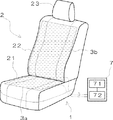
本発明の座席ヒータが設けられる座席は、例えば自動車等の車両に用いられる乗員用の座席を挙げることができるが、これに限られず、屋内用の座席等であってもよい。本座席ヒータは、座席の所定の領域に設けられる。前記「所定の領域」とは、座席ヒータにより加熱する対象の領域であり、以下では「ヒータ領域」という。例えば、図1に示す座席2は座面21と背もたれ22等からなっており、本座席ヒータ1の発熱部として、座面21のヒータ領域3aと、背もたれ22のヒータ領域3bが設けられている。座席に設けられるヒータ領域の位置、数、面積等は特に問わない。座面21の前(膝部)及び後(腰部)に分割されたり、背もたれ22の上部・下部に分割されたりして設けられても良い。また、座面や背もたれの全体ではなく部分的に設けられてもよいし、座席の脚乗せ(図示せず)等に設けられてもよい。
The seat provided with the seat heater of the present invention may be a passenger seat used in a vehicle such as an automobile, but is not limited thereto, and may be an indoor seat or the like. The seat heater is provided in a predetermined area of the seat. The “predetermined area” is an area to be heated by the seat heater, and is hereinafter referred to as a “heater area”. For example, the
本発明の座席ヒータ1では、座席のヒータ領域ごとに、発熱体を備える第1ヒータ(4)と、別の発熱体を備える第2ヒータ(5)とが設けられる。第1ヒータ及び第2ヒータの詳細については、図2以下において説明する。各ヒータ領域に備えられた第1ヒータ及び第2ヒータは、それぞれ制御手段により発熱が制御される。このため、制御手段を構成する制御部7は、各ヒータ領域ごとの第1ヒータ及び第2ヒータとそれぞれ接続され、各発熱部に電力を供給するように構成される。
In the
本座席ヒータの第1ヒータに用いる発熱体として、例えばニクロム線等を用いた線状の発熱体(線状発熱体)を使用することができる。また、第2ヒータに用いる発熱体として、上記線状発熱体のほか、平面状にカーボン被膜等の抵抗被膜等を形成した発熱体(面状発熱体)を使用することができる。各発熱体の具体的な形状や材料は特にこだわらない。例えば、線状発熱体は線材であってもよいし、基材上に線状に抵抗被膜を形成した発熱体であってもよい。また、線状発熱体を密に配列することによって面状発熱体を構成してもよい。また、後述するように、発熱体としてPTC特性やNTC特性を有する材料を適宜使用することができる。 As a heating element used for the first heater of the seat heater, for example, a linear heating element (linear heating element) using a nichrome wire or the like can be used. In addition to the linear heating element, a heating element (planar heating element) in which a resistance film such as a carbon film is formed in a planar shape can be used as the heating element used for the second heater. The specific shape and material of each heating element are not particularly particular. For example, the linear heating element may be a wire, or a heating element in which a resistance film is linearly formed on a substrate. Moreover, you may comprise a planar heating element by arranging a linear heating element closely. Further, as will be described later, a material having PTC characteristics and NTC characteristics can be appropriately used as the heating element.
図2は、座席ヒータが備える第1ヒータ及び第2ヒータの構成例と、それによる温度分布を説明するための図である。図2(a)〜(c)はヒータ領域3に設けられるヒータの構造を例示する平面図であり、同図(d)はそのヒータ領域上の位置を横軸として、座席の温度分布を示している。縦軸は温度であり、温度T0は、ヒータを使用しないときの座席の温度である。
FIG. 2 is a diagram for explaining a configuration example of the first heater and the second heater provided in the seat heater and a temperature distribution due thereto. 2A to 2C are plan views illustrating the structure of the heater provided in the
図2(a)は、線状発熱体4aを広い間隔で(粗に)設け、各線状発熱体4aを電気的に接続して構成したヒータ4を示している。図においては各線状発熱体4aが並列に接続されているが、直列に接続されてもよい。直列接続の場合には、ヒータ4全体を1本の線状発熱体を用いて構成することができる。このヒータ4aに一定の電力を供給すると、温度分布は図2(d)に示す曲線Aのように、各線状発熱体4aに沿った位置においては温度T2まで急速に上昇する。また、各線状発熱体4aの間隔が広いため、その中間の位置では温度はわずかに上昇するに止まる。暖房前の座席の温度に対して線状発熱体上の位置では高温(T2)になるため、着座者に強い温熱感を与えることができる。しかし、局所的に高温の状態が続いた場合、着座者に不快感を与えるおそれがある。
FIG. 2A shows a
図2(b)は、上記同様の線状発熱体5aを狭い間隔で(密に)設け、各線状発熱体5aを電気的に並列接続して構成したヒータ5を示している。前記同様に、各線状発熱体5aは直列に接続されてもよいし、ヒータ5全体を1本の線状発熱体を用いて構成することもできる。このヒータ5に一定の電力を供給すると、温度分布は図2(d)に示す曲線Bのように、中間の温度T1前後に上昇する。上記(a)の場合と比べて、ピーク点の温度は低くなるが、各線状発熱体5aが密に配設されているため、位置による温度の差が小さくなる。このため、着座者には穏やかな温熱感を与えることができる。しかし、同じ電力により発熱させた場合、この温度T1まで上昇する時間が上記(a)の場合に比べて長くなる。
FIG. 2B shows a
図2(c)は、ヒータ領域3の略全面に密に発熱体(面状発熱体)を設けたヒータ5’を示している。このヒータ5’に一定の電力を供給すると、温度分布は図2(d)に示す曲線Cのように、中間の温度T1程度に上昇する。発熱体が密に設けられているため、ヒータ領域全体に均一な温度分布となる。このため、着座者には図2(b)よりも更に穏やかな温熱感を与えることができる。しかし、同じ電力により発熱させた場合、この温度T1まで上昇する時間が、上記(a)の場合に比べて長くなる。
FIG. 2C shows a
図2(a)に示したような粗に発熱体を設けたヒータと、同図(b)や(c)に示したような密に発熱体を設けたヒータとを組み合わせることによって、速熱性と温度の均一性を兼ね備える座席ヒータを構成することができる。
本発明の座席ヒータは、ヒータ領域内に粗に設けられた線状発熱体からなる第1ヒータと、ヒータ領域内に密に設けられた発熱体からなる前記第2ヒータとを備える。ここで、第1ヒータの「粗に設けられる」とは、図2(a)に例示されるように、ヒータ領域全体に抵抗線等からなる線状発熱体を広い間隔で設けることをいう。また、上記「密に設けられる」とは、図2(b)に例示されるように、ヒータ領域全体に抵抗線等からなる線状発熱体を狭い間隔で設けること、又は図2(c)に例示されるように、ヒータ領域全体にわたり面状発熱体を設けることをいう。発熱体の間隔の広狭については、間隔が狭い場合には速熱性を与え、間隔が広い場合には温度分布の均一性を与える限り特に限定されず、ヒータの構造、発熱体の材料・寸法、座席表層の材料・構成等によって適宜に定めることができる。
Combining a heater with a rough heating element as shown in FIG. 2A and a heater with a dense heating element as shown in FIGS. And a seat heater having temperature uniformity can be configured.
The seat heater according to the present invention includes a first heater made of a linear heating element roughly provided in the heater region and the second heater made of a heating element densely provided in the heater region. Here, “roughly provided” of the first heater means that a linear heating element made of a resistance wire or the like is provided over the entire heater region at a wide interval, as illustrated in FIG. Further, the “densely provided” means that, as illustrated in FIG. 2B, linear heaters made of resistance wires or the like are provided in the entire heater region at a narrow interval, or FIG. As shown in Fig. 2, it means that a planar heating element is provided over the entire heater region. The width of the heating element is not particularly limited as long as it gives quick heat when the interval is narrow, and the temperature distribution is uniform when the interval is wide. The structure of the heater, the material and dimensions of the heating element, It can be determined as appropriate depending on the material and configuration of the seat surface.
本座席ヒータは、上記第1ヒータ及び第2ヒータの発熱制御を行う制御手段を備えている。この制御手段は、初期状態では第1ヒータを主に発熱させ、定常状態では第2ヒータを主に発熱させるように、各ヒータに供給する電力を制御する。
「初期状態」とは、座席ヒータの使用(通電)が開始されてから着座者が温熱を体感する程度にヒータの温度が上昇するまでの段階である。例えば、図2(a)に示したヒータが、最高発熱部位にて温度T2に達するまでの間とすることができる。
また、「定常状態」とは、その後、ヒータ領域全体が一様な温度分布とされ、その状態が維持される段階である。定常状態におけるヒータの目標温度は、着座者による選択や周囲温度等に基づいて別途決定することができる。定常状態は、例えば図2(b)又は(c)に示したヒータが、目標温度である温度T1程度に維持される状態とすることができる。これによって、本座席ヒータは、座席が冷えている状態で使用開始されたとき、主として第1ヒータに通電して急速に温度を上昇させ、着座者に強い温熱感を与えることができる。しかも、第1ヒータはヒータ領域全体にわたって配設されているので、局所のみが温度上昇して着座者に違和感を与えることがない。そして、第1ヒータにより温度が上昇した後は、主として第2ヒータに通電することにより、ヒータ領域全体にわたって一様な温度を維持することができる。
The seat heater includes control means for performing heat generation control of the first heater and the second heater. The control means controls the power supplied to each heater so that the first heater mainly generates heat in the initial state and the second heater mainly generates heat in the steady state.
The “initial state” is a stage from the start of use (energization) of the seat heater until the temperature of the heater rises to such an extent that the occupant feels the heat. For example, it can be set until the heater shown in FIG. 2A reaches the temperature T2 at the highest heat generation portion.
In addition, the “steady state” is a stage in which the entire heater region is thereafter uniformly distributed in temperature and the state is maintained. The target temperature of the heater in the steady state can be determined separately based on selection by the seated person, ambient temperature, and the like. The steady state can be a state in which, for example, the heater illustrated in FIG. 2B or 2C is maintained at a temperature T1 that is the target temperature. As a result, when the seat heater is started to be used while the seat is cold, the first heater is mainly energized to rapidly increase the temperature, thereby giving a strong thermal feeling to the seated person. And since the 1st heater is arrange | positioned over the whole heater area | region, only a local temperature rises and it does not give a discomfort to a seated person. After the temperature rises by the first heater, a uniform temperature can be maintained over the entire heater region by mainly energizing the second heater.
前記制御手段による第1ヒータの発熱と第2ヒータの発熱の制御は、適宜に構成することができる。例えば、初期状態においては第1ヒータのみに通電し、定常状態においては第2ヒータのみに通電するように切り替えることができる。また、初期状態と定常状態において、それぞれ所定の比率により第1ヒータ及び第2ヒータに電力を供給するようにしてもよい。初期状態から定常状態へ切り替えるための判断も適宜とすることができる。例えば、使用(通電)開始時から所定の時間が経過したとき、初期状態の発熱制御から定常状態の発熱制御に切り替えるようにすることができる。また、ヒータ又は座席表面の温度を検出することによって、定常状態に切り替えることもできる。また、温度によって抵抗値が変化するような発熱体を用いる場合には、その抵抗値等の変化を検出することによって、発熱制御を切り替えるようにしてもよい。
いずれの方法により第1ヒータの発熱及び第2ヒータの発熱を制御するにしても、制御手段により、初期状態と定常状態において座席ヒータ全体の使用電力を略同一とするように制御することができる。したがって、初期状態における急速な昇温のために余分な電力を使用する必要がないようにすることができる。
The control of the heat generation of the first heater and the heat generation of the second heater by the control means can be appropriately configured. For example, it is possible to switch so that only the first heater is energized in the initial state and only the second heater is energized in the steady state. Further, in the initial state and the steady state, electric power may be supplied to the first heater and the second heater at a predetermined ratio, respectively. Judgment for switching from the initial state to the steady state can be made as appropriate. For example, when a predetermined time has elapsed from the start of use (energization), the heat generation control in the initial state can be switched to the heat generation control in the steady state. It is also possible to switch to a steady state by detecting the temperature of the heater or seat surface. When a heating element whose resistance value changes with temperature is used, heat generation control may be switched by detecting a change in the resistance value or the like.
Whichever method is used to control the heat generation of the first heater and the heat generation of the second heater, the control means can control the power consumption of the entire seat heater to be substantially the same in the initial state and the steady state. . Therefore, it is possible to eliminate the need to use extra power for rapid temperature increase in the initial state.
制御手段は、図1に示した制御部7により構成することができる。制御部7は任意の場所に配設することができ、例えば、図1に示したように座席2と異なる場所とするほか、座席本体内部に配設したり、各ヒータ領域に一体に備えられたりしてもよい。また、座席制御用等のECUに含んで構成されてもよい。制御部7は、ハードウェアのみで構成されてもよいし、マイクロプロセッサ等を使用してハードウェアとソフトウェアとによって構成されてもよい。制御部7及び各ヒータ用の電源として、車両のバッテリ等から必要な電力を供給するようにすることができる。
The control means can be configured by the
具体的には、制御部7は、各ヒータ領域について初期状態又は定常状態を判断するための判断部71、判断した結果に基づいて各第1ヒータ及び各第2ヒータが所定の発熱量となるように通電を制御する通電制御部72を備えて構成することができる。着座者等がヒータの温度を調整するための操作部が別途に備えられている場合には、制御部7はそれによって設定された温度を目標温度として定常状態における発熱制御を行うことができる。また、ヒータ領域に温度センサが設けられている場合や、座席周辺の温度が計測されている場合には、それらによって検出された温度情報を基に判断し、各ヒータの発熱制御を行うことができる。
Specifically, the
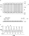
図3は、第1ヒータ及び第2ヒータをいずれも線状発熱体によって構成した座席ヒータ11を示す。座席ヒータ11は、ヒータ領域の全体にわたって配設される。図3(a)、(b)に示すように、第1ヒータ41は、第1の間隔d1で平行に配設された複数の線状発熱体41aを並列に接続して構成されている。第2ヒータ51は、ヒータ領域に第2の間隔d2で平行に配設された複数の線状発熱体51aを並列に接続して構成されている。そして、第1の間隔d1は第2の間隔の所定数倍(但し、整数に限られない)とされている。具体的には、間隔d1を20〜40mm、間隔d2を2〜10mm程度とすることができる。その場合、間隔d1は間隔d2の2〜20倍となる。すなわち、同じヒータ領域において、第2ヒータは第1ヒータの2〜20倍の本数の線状発熱体を備えていることとなる。第1ヒータを構成する線状発熱体と、第2ヒータを構成する線状発熱体とは、同一材料であってもよいし、異なっていてもよい。また、前記のとおり、第1ヒータ41及び第2ヒータ51は、それぞれ線状発熱体を直列に接続して構成されてもよい。
FIG. 3 shows a
上記座席ヒータ11の第1ヒータと第2ヒータの配設方法は、両者が電気的に絶縁されている限り任意とすることができる。例えば、図3(b)に示す同図(a)のX−X断面図に表わすように、絶縁物である基材61の1つの面に第1ヒータ41を設け、他の面に第2ヒータ51を備えるように構成することができる。基材61の材料は特に問わず、布、樹脂等によって構成することができる。第1ヒータ41及び第2ヒータ51が、基材61の一方の面に重ねて設けられてもよい。また、基材61は座席の表層を構成する部材であり、それと一体に第1ヒータ及び第2ヒータが形成されてもよい。座席ヒータ11は、第1ヒータ及び第2ヒータを基材と共に一体で形成することができる。
上記座席ヒータ11は、初期状態においては主に第1ヒータ41が発熱するため、図3(c)に示す曲線Aのように、各線状発熱体41aに沿った位置で高温T2となるような温度分布となる。そして、定常状態においては、主に第2ヒータが発熱するため、曲線Bに示すように、ヒータ領域内で温度T1前後の比較的一様な温度分布となる。
The arrangement method of the 1st heater and the 2nd heater of the said
In the initial state, the
図4は、第1ヒータを線状発熱体により構成し、第2ヒータを面状発熱体により構成した座席ヒータ12を示す。座席ヒータ12は、ヒータ領域の全体にわたって設けられている。図4(a)に示すように、第1ヒータ42は、所定の間隔で略平行に配設された複数の線状発熱体42aを直列に接続して構成され、第2ヒータ52は、ヒータ領域の全面に配設された面状発熱体52bである。第1ヒータを構成する線状発熱体42aの間隔は、前記座席ヒータ11の第1ヒータにおける線状発熱体の間隔d1と同様とすることができる。図4(a)では、各線状発熱体42aが直列に接続されている場合を示しているが、その全体が1本の線状発熱体であってもよい。また、各線状発熱体42aが並列に接続されて第1ヒータが構成されてもよい。
FIG. 4 shows a
上記第1ヒータと第2ヒータの配設方法は、両者が電気的に絶縁されている限り任意とすることができる。例えば、第1ヒータと第2ヒータとを重ねて配設することができる。また、図4(b)に示す同図(a)のX−X断面図に表すように、絶縁物である基材62の1つの面に第1ヒータ42を設け、他の面に第2ヒータ52を備えるように構成することができる。基材62、第1ヒータ42及び第2ヒータ52の配設・形成方法については、前記座席ヒータ11の場合と同様である。座席ヒータ12は、第1ヒータ及び第2ヒータを基材と共に一体で形成することができる。
上記座席ヒータ12は、初期状態においては主に第1ヒータ42が発熱するため、図4(c)に示す曲線Aに示すように、線状発熱体42aに沿った位置で高温T2となるような温度分布となる。そして、定常状態においては、主に第2ヒータ52が発熱するため、曲線Cに示すように、ヒータ領域内で温度T1程度の一様な温度分布となる。
The arrangement method of the first heater and the second heater can be arbitrary as long as both are electrically insulated. For example, the first heater and the second heater can be arranged to overlap each other. Moreover, as shown in the XX sectional view of FIG. 4A shown in FIG. 4B, the
Since the
図5は、ヒータ領域に多数配列されている線状発熱体の一部により第1ヒータを構成し、残る線状発熱体により第1ヒータを構成した座席ヒータ13を示す。図5(a)に示すように、ヒータ領域内に平行に配列された所定数以上の線状発熱体のうち、第1ヒータ43及び前記第2ヒータ53は、交互にそれぞれ所定の本数を並列接続し、第2ヒータ53を構成する線状発熱体53aの本数は、第1ヒータ43を構成する線状発熱体43aの本数の所定倍であるように構成される。すなわち、第1ヒータ43は、ヒータ領域に密に配列されている線状発熱体のうちから間隔を空けて抽出した線状発熱体43aを接続して構成され、第2ヒータは残る線状発熱体53aを接続して構成される。それぞれの接続方法は、並列であっても直列であってもよいが、図5(a)は並列に接続した場合を表わしている。
上記「所定数以上の線状発熱体」の本数は、上記のように各一定の本数を組として交互に並べて第1ヒータ及び第2ヒータを構成することができる限り、任意とすることができる。例えば、線状発熱体(43a及び53a)が5mmの間隔で配列されており、線状発熱体と垂直方向のヒータ領域の長さが300mmである場合、約60本の線状発熱体があることとなる。このうち、30mmごとにある1本の線状発熱体43aを用いて第1ヒータを構成すると、その間にある5本の線状発熱体53aが第2ヒータに用いられ、第2ヒータの線状発熱体53aは第1ヒータの線状発熱体43aの5倍の本数となる。上記「所定倍」については、前記座席ヒータ11における線状発熱体の間隔d1及びd2についての説明と同様に、第2ヒータは第1ヒータの2〜20倍の本数の線状発熱体とすることができる。
FIG. 5 shows the
The number of the above-mentioned “predetermined number or more of linear heating elements” can be arbitrarily set as long as the first heater and the second heater can be configured by alternately arranging a certain number as a set as described above. . For example, when the linear heating elements (43a and 53a) are arranged at an interval of 5 mm and the length of the heater region in the direction perpendicular to the linear heating elements is 300 mm, there are about 60 linear heating elements. It will be. Among these, when the first heater is configured by using one
上記第1ヒータと第2ヒータの配設方法は、両者が電気的に絶縁されている限り任意とすることができる。例えば、図5(b)に示す同図(a)のX−X断面図に表わすように、絶縁物である基材63の1つの面上に配列された多数の線状発熱体から第1ヒータ及び第2ヒータを構成することができる。基材63については前記同様である。
上記座席ヒータ13は、初期状態においては主に第1ヒータ43が発熱するため、図5(c)に示される曲線Aのように、各線状発熱体43aに沿った位置で高温T2となるような温度分布となる。そして、定常状態においては、主に第2ヒータ53が発熱するため、曲線Bに示すように、ヒータ領域内で温度T1前後の比較的一様な温度分布となる。
この座席ヒータ13は、1つの基材上に密に配列された同一素材の線状発熱体を用いて構成することができるため、第1ヒータ及び第2ヒータを基材と共に一体で形成することが容易である。
The arrangement method of the first heater and the second heater can be arbitrary as long as both are electrically insulated. For example, as shown in the XX sectional view of FIG. 5 (a) shown in FIG. 5 (b), first from a large number of linear heating elements arranged on one surface of the
In the initial state, the
Since the
本座席ヒータは、制御手段を図1に例示する制御回路14で構成するに限られず、第1ヒータの発熱体にPTC(Positive Temperature Coefficient)材料を用い、第2ヒータの発熱体にNTC(Negative Temperature Coefficient)材料を用いることができる。第1ヒータの発熱体の温度係数が正であり、第2ヒータの発熱体の温度係数が負である場合は、各温度係数を適宜選択した材料を用い、且つ各ヒータの線長や断面積を適宜選択することにより、座席ヒータの目標とする温度以下で第1ヒータの消費電力と第2ヒータの消費電力が一致するようにし、更に第1ヒータ及び第2ヒータを並列接続して作製することで、発熱体自身により温度制御を行うようにすることができる。
このとき、各ヒータの消費電力が一致する温度である均衡温度以下では第1ヒータが第2ヒータよりも低抵抗であるため、第1ヒータに主に電流が流れて高温になり、速熱性を達することができる。また、均衡温度以上では、第1ヒータが第2ヒータよりも高抵抗となるため、第2ヒータに主に電流が流れてヒータ領域全体が一様に発熱し、着座者に違和感を与えることがない。特に、第2ヒータを面状発熱体とすることで、均一な発熱となり、より着席者に違和感を与えないようにすることができる。
尚、PTC材料及びNTC材料は特にその材質を限定しないが、例えばPTC材料としてチタン酸バリウム化合物を挙げることができる。また、NTC材料としてリチウムマンガン酸化物、鉄シリサイド化合物(FeSi2)を挙げることができる。更に、NTC材料としてバナジウム酸化物等のCTRを用いることができる。
In this seat heater, the control means is not limited to the control circuit 14 illustrated in FIG. 1, but a PTC (Positive Temperature Coefficient) material is used for the heating element of the first heater, and the NTC (Negative) is used for the heating element of the second heater. Temperature Coefficient) material can be used. When the temperature coefficient of the heating element of the first heater is positive and the temperature coefficient of the heating element of the second heater is negative, a material in which each temperature coefficient is appropriately selected is used, and the line length and cross-sectional area of each heater are used. The power consumption of the first heater and the power consumption of the second heater coincide with each other below the target temperature of the seat heater, and the first heater and the second heater are connected in parallel. Thus, the temperature control can be performed by the heating element itself.
At this time, since the first heater has a lower resistance than the second heater below the equilibrium temperature, which is the temperature at which the power consumption of each heater coincides, the current mainly flows through the first heater to become a high temperature, and the rapid heating property is reduced. Can reach. In addition, since the first heater has a higher resistance than the second heater above the equilibrium temperature, a current mainly flows through the second heater, and the entire heater region generates heat uniformly, giving a sense of discomfort to the seated person. Absent. In particular, by using the second heater as a planar heating element, uniform heat generation can be achieved, and the seated person can be made more comfortable.
The material of the PTC material and the NTC material is not particularly limited. For example, a barium titanate compound can be used as the PTC material. Examples of the NTC material include lithium manganese oxide and iron silicide compound (FeSi 2 ). Furthermore, CTR such as vanadium oxide can be used as the NTC material.
1、11、12、13;座席ヒータ、2;座席、21;座面、22;背もたれ、3;ヒータ領域、4、41、42、43;第1ヒータ、4a、41a、42a、43a;線状発熱体、5、51、52、53;第2ヒータ、5a、51a、53a;線状発熱体、5b、52b;面状発熱体、61、62、63;基材、7;制御部(制御手段)。 1, 11, 12, 13; seat heater, 2; seat, 21; seat surface, 22; backrest, 3; heater region, 4, 41, 42, 43; first heater, 4a, 41a, 42a, 43a; Second heating element, 5a, 51a, 53a; linear heating element, 5b, 52b; planar heating element, 61, 62, 63; base material, 7; control unit ( Control means).
Claims (5)
前記座席の所定の領域に配設された第1ヒータ及び第2ヒータと、前記第1ヒータ及び前記第2ヒータの発熱制御を行う制御手段を備え、
前記第1ヒータは前記領域内に粗に設けられた線状発熱体からなり、前記第2ヒータは前記領域内に密に設けられた発熱体からなり、
前記制御手段は、初期状態では前記第1ヒータを主に発熱させ、定常状態では前記第2ヒータを主に発熱させることを特徴とする座席ヒータ。 A seat heater provided in the seat,
A first heater and a second heater disposed in a predetermined region of the seat; and a control means for performing heat generation control of the first heater and the second heater,
The first heater is composed of a linear heating element roughly provided in the region, and the second heater is composed of a heating element densely provided in the region,
The seat heater is characterized in that the control means mainly heats the first heater in an initial state and mainly heats the second heater in a steady state.
前記第2ヒータは、前記領域に第2の間隔で平行に配設された複数の線状発熱体を接続して構成され、
該第1の間隔は該第2の間隔の所定数倍である請求項1記載の座席ヒータ。 The first heater is configured by connecting a plurality of linear heating elements disposed in parallel to the region at a first interval,
The second heater is configured by connecting a plurality of linear heating elements disposed in parallel to the region at a second interval,
The seat heater according to claim 1, wherein the first interval is a predetermined number of times the second interval.
前記第2ヒータは、前記領域の全面に配設された面状発熱体であり、
該第1ヒータと該第2ヒータとが重ねて配設される請求項1記載の座席ヒータ。 The first heater is configured by connecting a plurality of linear heating elements arranged in parallel at a predetermined interval to the region,
The second heater is a planar heating element disposed on the entire surface of the region,
The seat heater according to claim 1, wherein the first heater and the second heater are arranged to overlap each other.
前記第1ヒータ及び前記第2ヒータは、交互に該線状発熱体のうちそれぞれ所定の本数を接続して構成され、
該第2ヒータを構成する該線状発熱体の本数は、該第1ヒータを構成する該線状発熱体の本数の所定倍である請求項1記載の座席ヒータ。 A predetermined number or more of linear heating elements are arranged in parallel in the region,
The first heater and the second heater are configured by alternately connecting a predetermined number of the linear heating elements,
The seat heater according to claim 1, wherein the number of the linear heating elements constituting the second heater is a predetermined multiple of the number of the linear heating elements constituting the first heater.
Priority Applications (1)
| Application Number | Priority Date | Filing Date | Title |
|---|---|---|---|
| JP2011009267A JP2012147970A (en) | 2011-01-19 | 2011-01-19 | Seat heater |
Applications Claiming Priority (1)
| Application Number | Priority Date | Filing Date | Title |
|---|---|---|---|
| JP2011009267A JP2012147970A (en) | 2011-01-19 | 2011-01-19 | Seat heater |
Publications (1)
| Publication Number | Publication Date |
|---|---|
| JP2012147970A true JP2012147970A (en) | 2012-08-09 |
Family
ID=46790860
Family Applications (1)
| Application Number | Title | Priority Date | Filing Date |
|---|---|---|---|
| JP2011009267A Pending JP2012147970A (en) | 2011-01-19 | 2011-01-19 | Seat heater |
Country Status (1)
| Country | Link |
|---|---|
| JP (1) | JP2012147970A (en) |
Cited By (3)
| Publication number | Priority date | Publication date | Assignee | Title |
|---|---|---|---|---|
| WO2018219081A1 (en) * | 2017-06-02 | 2018-12-06 | 盐城振宇科技发展有限公司 | Macromolecular ptc constant-temperature heated seat |
| WO2018219080A1 (en) * | 2017-06-02 | 2018-12-06 | 盐城振宇科技发展有限公司 | Macromolecular ptc constant-temperature heated seat |
| US10224585B2 (en) | 2013-09-20 | 2019-03-05 | Kabushiki Kaisha Toshiba | Battery heat radiation system, battery heat radiation unit |
-
2011
- 2011-01-19 JP JP2011009267A patent/JP2012147970A/en active Pending
Cited By (3)
| Publication number | Priority date | Publication date | Assignee | Title |
|---|---|---|---|---|
| US10224585B2 (en) | 2013-09-20 | 2019-03-05 | Kabushiki Kaisha Toshiba | Battery heat radiation system, battery heat radiation unit |
| WO2018219081A1 (en) * | 2017-06-02 | 2018-12-06 | 盐城振宇科技发展有限公司 | Macromolecular ptc constant-temperature heated seat |
| WO2018219080A1 (en) * | 2017-06-02 | 2018-12-06 | 盐城振宇科技发展有限公司 | Macromolecular ptc constant-temperature heated seat |
Similar Documents
| Publication | Publication Date | Title |
|---|---|---|
| US8066324B2 (en) | Reduced power heat mat | |
| EP2532543B1 (en) | Seat heater | |
| JP5636375B2 (en) | Seat heater | |
| JP5294420B2 (en) | Vehicle heating system | |
| JP5304895B2 (en) | Planar warmer and seat with the same | |
| JP6481497B2 (en) | Temperature control device | |
| US20170080779A1 (en) | Heating system for vehicle | |
| US11155190B2 (en) | Vehicle seat heater and vehicle seat | |
| JP2009269480A (en) | Heater for seat | |
| JP5708448B2 (en) | Vehicle seat | |
| JP4902283B2 (en) | Seat heater | |
| JP6284877B2 (en) | Vehicle seat | |
| JP5708292B2 (en) | Seat heater and vehicle seat provided with the same | |
| JP2008265716A (en) | Heater for vehicle | |
| JP2012147970A (en) | Seat heater | |
| JP2009247634A (en) | Heated seat | |
| JP6221985B2 (en) | Radiation heater device | |
| JPWO2007097445A1 (en) | Heater unit and vehicle seat heater | |
| JP2010040186A (en) | Heater apparatus | |
| JPH0473883A (en) | Heater device for vehicle | |
| JP2012100696A (en) | Seat heater | |
| JP2010089628A (en) | Heating device | |
| JP2013258055A (en) | Heating device for vehicle seat | |
| JP2008247375A (en) | Heating device for vehicle | |
| JP2024039748A (en) | Heater unit and vehicle seat |
Legal Events
| Date | Code | Title | Description |
|---|---|---|---|
| RD04 | Notification of resignation of power of attorney |
Free format text: JAPANESE INTERMEDIATE CODE: A7424 Effective date: 20120906 |