JP2011522505A - System and method for an array of multiple intelligent inverters - Google Patents
System and method for an array of multiple intelligent inverters Download PDFInfo
- Publication number
- JP2011522505A JP2011522505A JP2011509720A JP2011509720A JP2011522505A JP 2011522505 A JP2011522505 A JP 2011522505A JP 2011509720 A JP2011509720 A JP 2011509720A JP 2011509720 A JP2011509720 A JP 2011509720A JP 2011522505 A JP2011522505 A JP 2011522505A
- Authority
- JP
- Japan
- Prior art keywords
- power
- inverters
- inverter
- output
- array
- Prior art date
- Legal status (The legal status is an assumption and is not a legal conclusion. Google has not performed a legal analysis and makes no representation as to the accuracy of the status listed.)
- Pending
Links
Images


Classifications
-
- H—ELECTRICITY
- H02—GENERATION; CONVERSION OR DISTRIBUTION OF ELECTRIC POWER
- H02M—APPARATUS FOR CONVERSION BETWEEN AC AND AC, BETWEEN AC AND DC, OR BETWEEN DC AND DC, AND FOR USE WITH MAINS OR SIMILAR POWER SUPPLY SYSTEMS; CONVERSION OF DC OR AC INPUT POWER INTO SURGE OUTPUT POWER; CONTROL OR REGULATION THEREOF
- H02M1/00—Details of apparatus for conversion
- H02M1/0043—Converters switched with a phase shift, i.e. interleaved
-
- H—ELECTRICITY
- H02—GENERATION; CONVERSION OR DISTRIBUTION OF ELECTRIC POWER
- H02M—APPARATUS FOR CONVERSION BETWEEN AC AND AC, BETWEEN AC AND DC, OR BETWEEN DC AND DC, AND FOR USE WITH MAINS OR SIMILAR POWER SUPPLY SYSTEMS; CONVERSION OF DC OR AC INPUT POWER INTO SURGE OUTPUT POWER; CONTROL OR REGULATION THEREOF
- H02M7/00—Conversion of ac power input into dc power output; Conversion of dc power input into ac power output
- H02M7/42—Conversion of dc power input into ac power output without possibility of reversal
- H02M7/44—Conversion of dc power input into ac power output without possibility of reversal by static converters
- H02M7/48—Conversion of dc power input into ac power output without possibility of reversal by static converters using discharge tubes with control electrode or semiconductor devices with control electrode
- H02M7/493—Conversion of dc power input into ac power output without possibility of reversal by static converters using discharge tubes with control electrode or semiconductor devices with control electrode the static converters being arranged for operation in parallel
Abstract
【課題】 パワー発生アレイ(200)におけるDC・AC変換システム及び方法。
【解決手段】 本システム及び方法は、複数のソーラーパネル(205)からなるグループに結合されている多数のインバータ(220)を包含している。グループ制御器(250)が、該インバータ(220)のインターリーブ型スイッチングのために該インバータ(220)の動作を調整する。該グループ制御器(250)は、ローカルエリアネットワーク(245)、ワイアレスネットワーク(670)、又はその両方を介して、通信を行って、付加的なソーラーパネル(205)と並列に結合されている複数のインバータ(220)からなる付加的な複数のグループ(602,604,606)での動作を調整する。
【選択図】 図1APROBLEM TO BE SOLVED: To provide a DC / AC conversion system and method in a power generation array (200).
The system and method includes a number of inverters (220) coupled to a group of solar panels (205). A group controller (250) coordinates the operation of the inverter (220) for interleaved switching of the inverter (220). The group controller (250) communicates via a local area network (245), a wireless network (670), or both, and is coupled in parallel with an additional solar panel (205). The operation of the additional groups (602, 604, 606) of the inverters (220) is adjusted.
[Selection] Figure 1A
Description
本願は、大略、電気パワーシステムに関するものであって、更に詳細には、太陽電池パワーアレイからエネルギを変換するシステム及び方法に関するものである。 The present application relates generally to electrical power systems, and more particularly to systems and methods for converting energy from a solar cell power array.
光電セル(PV)パネル(以後、「ソーラーパネル(solar panel)」とも呼称する)は、電気エネルギを発生するために太陽からの放射光を使用する。ソーラーパネルは、太陽光を電気エネルギへ変換させるために多数のPVセルを包含している。大多数のソーラーパネルは、ウエハを基礎とした結晶性シリコンセルか又はカドミウム又はシリコンに基く薄膜セルを使用する。PVセルにおいてウエハ形態で通常使用される結晶性シリコンは、一般的に使用される半導体であるシリコンから派生される。PVセルは、光を直接的にエネルギへ変換させる半導体装置である。光がPVセルを照射すると、該セルにわたり電圧が発生し、且つ、負荷に接続された場合には、該セルを介して電流が流れる。その電圧及び電流は、セルの物理的寸法、セル上に照射される光量、セルの温度及び外部的ファクターを含む幾つかのファクターによって変化する。 Photocell (PV) panels (hereinafter also referred to as “solar panels”) use the emitted light from the sun to generate electrical energy. A solar panel includes a number of PV cells to convert sunlight into electrical energy. Most solar panels use wafer-based crystalline silicon cells or thin film cells based on cadmium or silicon. Crystalline silicon commonly used in wafer form in PV cells is derived from silicon, which is a commonly used semiconductor. A PV cell is a semiconductor device that converts light directly into energy. When light illuminates a PV cell, a voltage is generated across the cell, and when connected to a load, a current flows through the cell. The voltage and current will vary depending on several factors including the physical dimensions of the cell, the amount of light irradiated on the cell, the temperature of the cell and external factors.
ソーラーパネル(PVモジュールとも呼称される)は、直列及び並列に配列された複数個のPVセルから構成されている。例えば、PVセルは、最初に、1つのグループ内において直列に結合される。次いで、これらの多数のグループが並列に結合される。同様に、PVアレイ(「ソーラーアレイ(solar array)」とも呼称される)は直列及び並列に配列された複数個のソーラーパネルから構成される。互いに物理的に近接して位置される2個又はそれ以上のPVアレイはPVアレイサイト(site)と呼称される。 A solar panel (also referred to as a PV module) is composed of a plurality of PV cells arranged in series and in parallel. For example, PV cells are first coupled in series within a group. These multiple groups are then combined in parallel. Similarly, a PV array (also referred to as a “solar array”) is composed of a plurality of solar panels arranged in series and in parallel. Two or more PV arrays that are located in physical proximity to each other are referred to as PV array sites.
各ソーラーパネルによって発生される電気的パワーはソーラーパネルの電圧及び電流によって決定される。ソーラーアレイにおいては、電気的接続部は、所望の出力ストリング(string)電圧を達成するために直列に形成され、及び/又は、所望の量のストリング電流源能力を与えるために並列に形成される。幾つかの場合において、各パネル電圧はDC−DCコンバータでブーストされるか又はバックされる。 The electrical power generated by each solar panel is determined by the voltage and current of the solar panel. In solar arrays, the electrical connections are formed in series to achieve the desired output string voltage and / or in parallel to provide the desired amount of string current source capability. . In some cases, each panel voltage is boosted or bucked with a DC-DC converter.
ソーラーアレイは、電気的負荷、電気的グリッド又はこれに制限されるものではないがバッテリセル即ち電池などの電気的パワー格納装置へ接続される。ソーラーパネルは直流(DC)電気的パワーを送給する。電気的負荷、電気的グリッド又は電気的パワー格納装置が交流(AC)を使用して動作する場合には(例えば、毎秒60サイクル、即ち60ヘルツ(Hz))、ソーラーアレイはDC−AC変換器を介して電気的負荷、電気的グリッド、又は電気的パワー格納装置へ接続される。 The solar array is connected to an electrical load, an electrical grid or an electrical power storage device such as but not limited to a battery cell. Solar panels deliver direct current (DC) electrical power. When an electrical load, electrical grid, or electrical power storage device operates using alternating current (AC) (eg, 60 cycles per second, or 60 hertz (Hz)), the solar array is a DC-AC converter. Through an electrical load, an electrical grid, or an electrical power storage device.
ソーラーパネルは、そのI−V曲線によって記述される電圧及び電流特性を示す。ソーラーセルが負荷へ接続されていない場合には、それの端子を横断しての電圧はその開回路電圧Vocである。該端子が一緒に接続されて短絡回路を形成している場合には、短絡回路電流Iscが発生される。両方の場合に、パワーは電圧に電流を乗算したもので与えられるので、パワーが発生されることはない。最大パワーポイント(MPP)はソーラーパネルが最大パワーで動作するポイントを定義する。 A solar panel exhibits voltage and current characteristics described by its IV curve. If the solar cell is not connected to a load, the voltage across its terminals is its open circuit voltage V oc . When the terminals are connected together to form a short circuit, a short circuit current Isc is generated. In both cases, no power is generated because the power is given by the voltage multiplied by the current. Maximum power point (MPP) defines the point at which the solar panel operates at maximum power.
従来のソーラーアレイにおいては、ソーラーアレイにおける個々のソーラーパネルは該アレイが適切に動作するためには完全に太陽光を受光せねばならない。該アレイの一部に陰が付いている(「shaded」)か、又はその他の態様で欠陥的である場合には、全体的なアレイのパワー出力は、たとえこれらのセクションからのパワー出力が未だに太陽光に露呈されているものであっても、低下される。不可避的に、パネル間の効率を減少させる変動も多くのソーラーアレイ内に存在する。従って、これらの変動が検知されず且つ補正されないままの場合には、かなりの量のエネルギが実現されないままとなる。 In a conventional solar array, each individual solar panel in the solar array must receive sunlight completely for the array to operate properly. If a portion of the array is shaded (“shaded”) or otherwise defective, the overall array power output is still the power output from these sections. Even those exposed to sunlight are reduced. Inevitably, there are also variations in many solar arrays that reduce the efficiency between panels. Thus, if these variations remain undetected and uncorrected, a significant amount of energy remains unrealized.
単一のソーラーパネルによって発生されるDCパワーをACパワーへ変換する「マイクロインバーター」を製造する試みが従来なされている。パネル当たり(モジュール当たりとも呼称される)の変換は、局所化された最大パワーポイントトラッキング(MPPT)及び時間の経過に従い古いソーラーパネルを新しいものと置換することの能力を包含する重要な利点を与える。古いソーラーパネルの置換は、ソーラーアレイ内の古いものである蓋然性の高い既存のソーラーパネルの電圧及び電流特性とマッチさせる必要性無しで実施することが可能である。 Attempts have been made to produce “micro inverters” that convert DC power generated by a single solar panel into AC power. Per-panel (also called per-module) conversion provides important advantages including localized maximum power point tracking (MPPT) and the ability to replace old solar panels with new ones over time. Replacement of the old solar panel can be performed without the need to match the voltage and current characteristics of an existing solar panel that is likely to be old in the solar array.
然しながら、この様な従来のシステムにおいては、既存のソーラーパネルは、例えば120V単相に対してほぼ200V又は208V3相に対して300Vである、ACパワーグリッド上で見られるピーク電圧より下側の電圧において動作する。そのために、この様な従来のシステムはブーストステージを包含せねばならない。ブーストステージは一層複雑な回路を必要とし、それは高価なものである可能性があり且つ信頼性のないコンポーネントである可能性のある変圧器を包含している。
However, in such a conventional system, the existing solar panel has a voltage below the peak voltage seen on the AC power grid, eg, approximately 200V for 120V single phase or 300V for
従来のインバーターデザインにはトレードオフが存在している。インバーターデザインにおけるトレードオフは、パルス幅変調(PWM)スイッチング周波数に関連している。一層高い周波数はグリッドトラッキングの正確度を増加させ、従って、高調波歪を減少させる。然しながら、一層高い周波数は一層多くのスイッチングとなる。スイッチングが増加するとスイッチング損失に起因して効率を減少させる。 There are trade-offs in conventional inverter design. The trade-off in inverter design is related to pulse width modulation (PWM) switching frequency. Higher frequencies increase the accuracy of grid tracking and thus reduce harmonic distortion. However, higher frequencies result in more switching. Increasing switching reduces efficiency due to switching losses.
更に、物理的寸法及び基板インダクタ上のインダクタンスに関連するトレードオフがインダクタデザインに存在している。大型で高いインダクタンスのインダクタは、高調波歪が最小である。然しながら、大型で高いインダクタンスのインダクタは、金銭的コスト及び物理的空間の両方において高価なものである。 In addition, there are tradeoffs in inductor design related to physical dimensions and inductance on the substrate inductor. Large, high inductance inductors have minimal harmonic distortion. However, large, high inductance inductors are expensive in both financial cost and physical space.
ソーラーセルパワーシステムにおいて使用するソーラーパネルアレイが提供される。ソーラーパネルアレイは多数のソーラーパネルを包含している。ソーラーパネルアレイは、又、ソーラーパネルに並列に結合されている複数個のインバーターを包含している。少なくとも1個のグループ制御器が、該複数個のインバーターの動作がインターリーブ型スイッチングを実施すべく調整する形態とされている。 A solar panel array for use in a solar cell power system is provided. A solar panel array includes a number of solar panels. The solar panel array also includes a plurality of inverters coupled in parallel to the solar panel. At least one group controller is configured to adjust the operation of the plurality of inverters to perform interleaved switching.
ソーラーセルパワーシステムにおいて使用するコンバーター即ち変換器が設けられる。該変換器は、該多数のソーラーパネルの正端子へ結合すべく適合されている第1入力端子を包含している。該変換器は、更に、第1入力端子へ結合されている第1高側スイッチと、第1入力端子へ結合されている第2高側スイッチと、第1高側スイッチ及び第1出力端子間に結合されている第1インダクタと、第2高側スイッチ及び第2出力端子間に結合されている第2インダクタと、第1出力へ結合されている第1プルダウンスイッチと、第2出力へ結合されている第2プルダウンスイッチと、制御器とを包含している。該制御器は、第1及び第2高側スイッチ及び第1及び第2プルダウンスイッチの動作を変化させる形態とされている。 A converter for use in the solar cell power system is provided. The converter includes a first input terminal adapted to couple to the positive terminals of the multiple solar panels. The converter further includes a first high side switch coupled to the first input terminal, a second high side switch coupled to the first input terminal, and between the first high side switch and the first output terminal. A first inductor coupled to the second high-side switch and a second inductor coupled between the second output terminal, a first pull-down switch coupled to the first output, and a second output coupled to the second output. A second pull-down switch, and a controller. The controller is configured to change the operation of the first and second high-side switches and the first and second pull-down switches.
光電アレイ用電流変換方法が提供される。該方法は、複数個のソーラーパネルから複数個のインバーターによって電気的エネルギを受け取ることを包含している。該インバーターのスイッチングは、該複数個のインバーターによって直流エネルギを交流エネルギへインターリーブ型変換を実施するために調整される。 A current conversion method for a photoelectric array is provided. The method includes receiving electrical energy from a plurality of solar panels by a plurality of inverters. The switching of the inverter is adjusted to perform an interleaved conversion of DC energy to AC energy by the plurality of inverters.
以下の本発明の詳細な説明を行なう前に、この特許文書全体にわたり使用される或る単語及び語句の定義を説明することが有益的であると思われる。「パケット」という用語は、特定の通信信号に対して使用されるフォーマットにかかわらずに、任意の情報を担持する通信信号のことを意味している。「アプリケーション」、「プログラム」、「ルーチン」等の用語は、1個又はそれ以上のコンピュータプログラム、複数組の命令、手順、機能、オブジェクト、クラス、インスタンス、又は適宜のコンピュータ言語で実現するために適合された関連するデータのことを意味している。「結合」という用語及びその派生語は、互いに物理的に接触しているか否かにかかわらずに2個又はそれ以上の要素間における任意の直接的又は間接的な通信のことを意味している。「送信」、「受信」、及び「通信」等の用語及びそれらの派生語は、直接的及び間接的な両方の通信を包含している。「含む」及び「有する」等の用語及びそれらの派生語は、制限無しでの包含を意味している。「又は」という用語は、包含的なものであって、及び/又はを意味している。「と関連する」及び「それと関連する」という語句及びそれらの派生語句は、包含すること、その中に包含されること、それと相互接続すること、含有すること、その中に含有されること、それへ又はそれで接続すること、それへ又はそれと結合すること、それと通信可能であること、それと協働すること、インターリーブすること、並置すること、それに近接していること、それに対して又はそれで束縛されること、その特性を持つこと等を意味する場合がある。「制御器」という用語は、少なくとも1個の動作を制御する任意の装置、システム、又はその一部を意味している。制御器は、ハードウエア、ファームウエア、ソフトウエア、又は少なくともこれらの内の2つの何らかの結合で実現することが可能である。任意の特定の制御器と関連する機能性は、局所的であるか又は遠隔的であるかにかかわらずに、集中型又は分散型とすることが可能である。 Before the following detailed description of the present invention, it may be beneficial to explain certain word and phrase definitions used throughout this patent document. The term “packet” means a communication signal that carries any information, regardless of the format used for the particular communication signal. The terms “application”, “program”, “routine”, etc. are intended to be implemented in one or more computer programs, sets of instructions, procedures, functions, objects, classes, instances, or any suitable computer language. It means relevant data that has been adapted. The term “coupled” and its derivatives refer to any direct or indirect communication between two or more elements, whether or not they are in physical contact with each other. . Terms such as “transmit”, “receive”, and “communication” and their derivatives encompass both direct and indirect communication. Terms such as “including” and “having” and their derivatives mean inclusion without limitation. The term “or” is inclusive, meaning and / or. The phrases “related to” and “related to” and their derivatives are included, included in, interconnected with, included, included in, Bind to or connect to it, be connected to it, be communicable with it, cooperate with it, interleave, juxtapose, be in close proximity to it, bind to it or on it It may mean that it has a characteristic or that. The term “controller” means any device, system, or part thereof that controls at least one operation. The controller can be implemented in hardware, firmware, software, or at least some combination of two of these. The functionality associated with any particular controller can be centralized or distributed, whether local or remote.
以下に説明する図1A乃至10及び本特許文書における本開示の原理を説明するために使用する種々の実施例は単に例示的なものであり、本開示の範囲を何ら制限するような態様で解釈されるべきものではない。本開示の原理は任意の適宜に構成された光電アレイシステムにおいて実現することが可能であることは当業者が理解するものである。 The various embodiments used to illustrate the principles of the present disclosure in FIGS. 1A through 10 and the patent document described below are merely exemplary and are interpreted in a manner that will limit the scope of the present disclosure in any way. Should not be done. Those skilled in the art will appreciate that the principles of the present disclosure can be implemented in any suitably configured photoelectric array system.
本開示の範囲はDCエネルギをACエネルギへ変換すべく適合された複数のパワーインバータからなるアレイに関するものである。ここで説明する実施例は、ソーラーアレイ内の1個又はそれ以上のソーラーパネル等のソーラーエネルギ発生装置に結合されているパワーインバータについて説明するが、パワーインバータは風力発電機又は風力発電機ファーム、地熱エネルギ発生装置、及び水(ハイドロ)又は波力発電装置、又は同様なパワー源等で、且つこれらに制限されるものではない、任意のDCエネルギ発生装置へ結合させることが可能であり、且つそれからDCエネルギを受け取ることが可能である。 The scope of this disclosure relates to an array of power inverters adapted to convert DC energy to AC energy. The embodiments described herein describe a power inverter that is coupled to a solar energy generator, such as one or more solar panels in a solar array, where the power inverter is a wind generator or a wind generator farm, Can be coupled to any DC energy generator, such as, but not limited to, a geothermal energy generator and a water or wave power generator, or similar power source, and It is then possible to receive DC energy.
図1Aは本開示の実施例に基くソーラーアレイの概略図を例示している。図1Aに示したソーラーアレイ100の実施例は、単に例示的なものであるに過ぎない。ソーラーアレイのその他の実施例は本開示の範囲から逸脱すること無しに使用することが可能である。
FIG. 1A illustrates a schematic diagram of a solar array according to an embodiment of the present disclosure. The embodiment of the
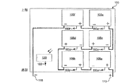
ソーラーアレイ100を形成するためにどのようにして複数のパネル105を一緒に接続するかの非制限的な例を図1Aに示してある。ソーラーアレイ100は6個のソーラーパネル105を包含している。理解されるように、6個のソーラーパネル105の例は例示的なものに過ぎず、ソーラーアレイは任意の数のソーラーパネル105を包含することが可能である。ソーラーパネル105は、例えば、上から下へ配列されて、各々が2個のパネルからなる3個の行に直列に結合されている。例えば、ソーラーアレイ100は、単一列のストリングによって形成することが可能である。ソーラーパネル105は、第1ソーラーパネル105aの負端子が第2ソーラーパネル105bの正端子へ結合され、第2ソーラーパネル105bの負端子が第3ソーラーパネル105cの正端子へ結合される、等々のように結合されている。更に、第1ソーラーパネル105aの正端子はソーラーアレイ100の正出力端子110へ結合されている。幾つかの実施例においては、第1ソーラーパネル105aの正端子はソーラーアレイ100の正出力端子110である。更に、最後のソーラーパネル105fの負端子はソーラーアレイ100の負出力端子115へ結合されている。幾つかの実施例においては、最後のソーラーパネル105fの負端子はソーラーアレイ100の負出力端子115である。
A non-limiting example of how
ソーラーアレイ100は全天日射計(pyranometer)120又は太陽放射センサーを包含している。いくつかの実施例においては、全天日射計はソーラーアレイ100に近接して独立的に装着されている。付加的な且つ代替的な実施例においては、全天日射計はソーラーアレイ100上に装着されている。全天日射計120は、平坦な表面上の広帯域の太陽放射照度を測定するために使用される日射計の一つのタイプである。全天日射計120は、華氏180度(180°F)の視界から太陽放射束密度(ワット/平方メートル)を測定する形態とされているセンサーである。全天日射計120は、ソーラーアレイ100における測定した広帯域の太陽放射照度に対応するデータを送信するために、データ線122へ結合されている。全天日射計120のデータ出力はソーラーアレイ100上に入射する太陽光の量に比例する。
The
図1Bは本開示の実施例に基くソーラーパネル105の概略図を例示している。図1Bに示したソーラーパネル105の実施例は単に例示的なものに過ぎない。ソーラーパネル105のその他の実施例を本開示の範囲を逸脱すること無しに使用することが可能である。
FIG. 1B illustrates a schematic diagram of a
幾つかの実施例においては、1個又はそれ以上のソーラーパネル105内の複数のPVセル125からなる複数のストリング(列)が並列に結合されている。例えば、ソーラーパネル105において、複数のPVセル125からなる第1ストリング130が、複数のPVセル125からなる第2ストリング140と並列に結合されている、等々である。理解されるように、2つのストリング130,135の例は単に例示的なものに過ぎず、ソーラーパネル105は任意の数のストリングを包含することが可能である。
In some embodiments, multiple strings of
各ストリング130,135は、第1PVセル125の負端子が第2PVセル125の正端子へ結合される、等々のように直列に結合されている多数のPVセル125を包含している。更に、各ストリング120,135は、バイパスダイオード140を包含している。各ストリング130,135において、バイパスダイオード140は、第1PVセル125の正端子とソーラーパネル105の正端子145との間に結合されている。各ストリング130,135において、ソーラーパネル105の負端子150は最後のPVセル125の負端子へ結合されている。
Each
バイパスダイオード140は、ソーラーパネル105に対して短絡回路保護を与える。光電セル125は、特別に構成されたPN接合であり且つ高い電流の流れの下で高外気温において動作している場合にショートする場合がある。ストリング130,135内の1個のPVセル125がショートする場合には、ショートしたPVセル125を有するストリング130,135の電圧は他のストリング130,135の電圧より下側に降下することとなる。例えば、第1ストリング130内のPVセル125がショートすると、第1ストリング130の電圧は第2ストリング135の電圧より1個のダイオード電圧降下を超えて降下することとなる。従って、バイパスダイオード140は逆バイアスされ且つ導通状態を停止し、ショートしたPVセル125を有するストリング135は全ソーラーパネル105に対して短絡回路となることはない。
The
ソーラーパネル105は温度センサー155を包含している。幾つかの実施例においては、温度センサー155はソーラーパネル105上に装着されている。温度センサー155は、ソーラーパネル105における又はその上の温度をモニターする形態とされている。温度センサー155はデータ出力線160へ結合されている。各ソーラーパネル105は対応する温度データ出力線160を包含している。例えば、図1Aに例示した如く、ソーラーパネル105aは温度データ出力線160aを包含しており、ソーラーパネル105bは温度データ出力線160bを包含しており、ソーラーパネル150cは温度データ出力線160cを包含しており、ソーラーパネル105dは温度データ出力線160dを包含しており、ソーラーパネル105eは温度データ出力線160eを包含しており、ソーラーパネル105fは温度データ出力線160fを包含している。
The
図1Cは、本開示の実施例に基く、ネットワーク接続を介してデータを送信する例示的な温度データ出力線及び全天日射計データ線を例示している。図1Cに示したネットワーク接続を介してデータを送信するこの実施例の温度センサー及び全天日射計は単に例示的なものに過ぎない。本開示の範囲を逸脱すること無しにその他の実施例を使用することが可能である。 FIG. 1C illustrates an exemplary temperature data output line and a solar radiation data line that transmit data over a network connection, according to an embodiment of the present disclosure. The temperature sensor and global anemometer of this embodiment that transmits data over the network connection shown in FIG. 1C is merely exemplary. Other embodiments may be used without departing from the scope of this disclosure.
温度出力データ線160a−160f、例えば、ソーラーアレイ100に対する温度出力データ線160、はネットワーク接続165を介してソーラーサイトマネージャへ結合されている。更に、全天日射計120からのデータ線122もネットワーク接続165を介して該サイトマネージャへ結合されている。該ネットワーク接続は、ローカルエリアネットワーク(LAN)接続、ワイドエリアネットワーク(WAN)接続、ワイアライン接続、ワイアレス接続、又はこれらの組み合わせとすることが可能である。
Temperature
図2は、本開示の実施例に基くインテリジェントインバータを包含しているソーラーアレイの概略図を例示している。図2に示したソーラーアレイ200の実施例は例示的なものに過ぎない。本開示の範囲を逸脱すること無しにその他の実施例を使用することが可能である。
FIG. 2 illustrates a schematic diagram of a solar array including an intelligent inverter according to an embodiment of the present disclosure. The embodiment of the
該ソーラーサイトは多数のソーラーパネル205を包含している。ソーラーパネル205は、上述したソーラーパネル105と同じ構成及び形態のものとすることが可能である。これらのソーラーパネル205は直列に結合されており、即ち第1ソーラーパネル205aの負端子は第2ソーラーパネル205bの正端子へ結合されており、第2ソーラーパネル205bの負端子は第3ソーラーパネル205cの正端子へ結合されており、且つ第3ソーラーパネル205cの負端子は第4ソーラーパネル205dの正端子へ結合されている。理解されるように、4個のソーラーパネル205の例示は単に例としてのものに過ぎず、ソーラーアレイ200は任意の数のソーラーパネル205を包含することが可能なものである。
The solar site includes a number of solar panels 205. The solar panel 205 can have the same configuration and form as the
最後のソーラーパネル205dの負端子は負(−)DCパワーライン210へ結合されている。第1ソーラーパネル205aの正端子は正(+)DCパワーライン215へ結合されている。
The negative terminal of the last
多数のパワーインバータ220がDCパワーライン210,215へ結合されている。例えば、各パワーインバータ220はその負DCパワー入力(−)222を負DCパワーライン210へ結合しており、且つその正DCパワー入力(+)224を正DCパワーライン215へ結合している。
A number of power inverters 220 are coupled to the
個々のパワーインバータ220の各々は、夫々のAC正弦波に対応する複数個の出力線A,B,Cを包含している。AC電気系は3相の正弦波で動作する。正弦波電圧は接地に関して測定され、従って、正のピークと負のピークとを有している。3つの相は、夫々、「A」、「B」、「C」として示してある。各相は120度(120°)だけ次の相から離隔されている。従って、各相A,B,Cに対する正及び負のピークは、他の相のAC電圧に対して異なる位相を有している。パワーインバータ220は、各相が対応する相に接続されるように(例えば、同一のピーク電圧タイミング又は同一のフェージング即ち整相を有している)出力線A,B,Cを介して互いに結合されている。例えば、第1インバータ220aの出力線Aは第2及び第3インバータ220b及び220cの各々の出力線Aへ結合されており、第1インバータ220aの出力線Bは第2及び第3インバータ220b及び220cの各々の出力線Bへ結合されており、且つ第1インバータ220aの出力線Cは第2及び第3インバータ220b及び220cの各々の出力線Cへ結合されている。各同一の位相とされたインバータ220出力線は多数のAC出力線230,232,234の一つへ結合されている。例えば、インバータ220の各々からの出力線AはAC出力線230へ結合されており、インバータ220の各々からの出力線BはAC出力線232へ結合されており、且つインバータ220の各々からの出力線CはAC出力線234へ結合されている。
Each of the individual power inverters 220 includes a plurality of output lines A, B, C corresponding to respective AC sine waves. The AC electrical system operates with a three-phase sine wave. The sinusoidal voltage is measured with respect to ground and thus has a positive peak and a negative peak. The three phases are shown as “A”, “B”, and “C”, respectively. Each phase is separated from the next phase by 120 degrees (120 °). Therefore, the positive and negative peaks for each phase A, B, C have different phases with respect to the AC voltages of the other phases. The power inverter 220 is coupled to each other via output lines A, B, C so that each phase is connected to a corresponding phase (eg, having the same peak voltage timing or the same fading or phasing). Has been. For example, the output line A of the
パワーインバータ220は内部ACスイッチング装置240を包含している。スイッチング装置240はインバータ220によって内部的に発生される制御信号に応答する。スイッチング装置240は、ソーラーアレイ200の出力パワーが或る(例えば、特定された)スレッシュホールドの上側にあり且つ安定している場合に、個々のパワーインバータ出力A,B,Cを出力線230,232,234へ結合させる。スイッチング装置240は、切断イベントに応答して出力線230,232,234からインバータ220を切断させる(例えば、結合を切る)形態とされている。切断イベントは、これらに制限されるべきものではないが、インバータ220の過熱、インバータ220の故障、グループ制御器250からネットワーク245を介してインバータ220へ送信される切断コマンド、を包含することが可能である。ネットワーク245は、ワイアライン又はワイアレス通信媒体を介して確立されるLAN接続又はWAN接続とすることが可能である。
The power inverter 220 includes an internal
各インバータ220はデータ接続255を介してネットワーク245へ結合されている。幾つかの実施例においては、データ接続255はマルチワイヤデジタルデータ線接続である。ネットワーク245は、パワーインバータ220内及びグループ制御器250内の内部ラインドライバ(特に例示していない)と共に、RS−485等の当該技術において周知のプロトコルを使用してデジタルデータの双方向(例えば、2方向)の流れを可能とする。
Each inverter 220 is coupled to a
グループ制御器250は、1個又はそれ以上のプロセッサと、各インバータ220からの出力電圧データ及び電流データを受け取り且つ格納する形態とされているメモリ装置と、を包含している。グループ制御器250は、ネットワーク245によりインバータグループ内の複数のインバータ220からの出力電圧データ及び電流データを受け取る。グループ制御器250は、該インバータグループ内のインバータ220の出力パワーを該出力パワーの最適パワー帯域又は最小変換損失範囲内に維持するために、受け取った出力電圧データ及び電流データを使用すべく適合されている。
各ソーラーパネル205内に包含されている1個又はそれ以上の温度及び/又は電圧センサー270及び1個又はそれ以上の輻射計(例えば、特に例示していない全天日射計)がネットワーク245を介してデータをグループ制御器250へ送信する。グループ制御器250は、太陽エネルギの電気的パワーへの変換をMPPに維持するために出力電流を変化させるために、ネットワーク245を介して、パワーインバータ220へコマンドを送信する。付加的に且つ代替的に、グループ制御器250は、ソーラーパネル205及びパワーインバータ220から回収したデータをワイアレスデータネットワークを介してワイアレスデータ送信機/受信機260及びアンテナ265を使用して中央ファシリティ(不図示)へ送ることが可能である。幾つかの実施例においては、グループ制御器250は、これに制限されるべきものではないが、通信ポート又はモデム等のワイアラインインターフェース(不図示)を使用してワイアラインデータネットワークを介して該中央ファシリティへデータを送る。グループ制御器250は、アンテナ265及び送信機/受信機260を介して中央ファシリティから受けとったコマンドに応答する。受け取ったコマンドは、これに制限されるものではないが、ソーラーアレイ200における1個又はそれ以上の要素の検査及び維持のために必要とされるようなインバータグループシャットダウンコマンドを包含することが可能である。
One or more temperature and / or
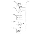
図3は本開示の実施例に基づくインテリジェントインバータスイッチング動作を例示している。図3に示した動作300の実施例は例示的なものに過ぎない。本開示の範囲を逸脱すること無しにその他の実施例を使用することが可能である。
FIG. 3 illustrates intelligent inverter switching operation according to an embodiment of the present disclosure. The embodiment of
該インバータの内の1個又はそれ以上はステップ305においてイネーブル、即ち動作可能状態とされる。従って、イネーブルされたインバータは、これに制限されるものではないが、電気分配グリッド等のAC電気的負荷へパワーを出力する。
One or more of the inverters are enabled or enabled in
ステップ310において、インバータの出力パワーは該インバータに対する最適パワー帯域の上側パワー限界に対して測定される。該パワーは、該インバータによって個別的に測定することが可能であり、該インバータから受け取ったデータを使用してグループ制御器によって測定することが可能であり、又はこれらの両方によって測定することが可能である。出力パワーが該インバータに対する最適パワー帯域の上側限界を超えるものではない場合には、本処理はステップ310において繰り返し、その場合に、出力パワーは断続的に又は特定した間隔で測定される。
In
動作中のインバータの出力パワーが1個のインバータに対する最適パワー帯域の上側パワー限界の上側に移行する場合には、該グループ内の2番目の(例えば、別の)インバータがステップ315においてイネーブルされる。付加的なインバータ(例えば、以前に1個のインバータがイネーブルされている場合には2番目のインバータであり、以前に2個のインバータがイネーブルされている場合には3番目のインバータである、等々)は、全出力パワーがそれらのインバータ間で分担されるようにイネーブルされる。例えば、2番目のインバータがイネーブルされる場合には、これらの2個の動作中のインバータは、以前は1個のインバータに対する最適パワー帯域の上側パワー限界であった全出力パワーの50%を分担することとなる。従って、これらの2個の動作中のインバータは最適なパワー帯域内において動作するが、該最適パワー帯域の下側パワー限界近くである。
If the output power of the active inverter moves above the upper power limit of the optimum power band for one inverter, the second (eg, another) inverter in the group is enabled in
付加的な例において、該グループ内の2個のインバータが以前にイネーブルされており且つこれらの2個の動作中のインバータの出力パワーがステップ310において2個のインバータに対する最適パワー帯域の上側パワー限界の上側へ移行する場合には、該グループ内の3番目のインバータがイネーブルされ、その結果これら3個の動作中のインバータは2個のインバータに対する最適パワー帯域の上側パワー限界であったパワーの三分の一(例えば、33.3%)を分担する。従って、これら3個の動作中のインバータは最適パワー帯域内において動作する。
In an additional example, the two inverters in the group have been previously enabled, and the output power of these two active inverters is the upper power limit of the optimum power band for the two inverters at
1個を超えるパワーインバータがイネーブルされる場合には、グループ制御器は該インバータの出力パワーを測定し且つその測定値をステップ320において最適パワー帯域の下側パワー限界に対して比較する。パワーは各インバータによって個別的に測定することが可能であり、それらのインバータから受け取ったデータを使用してグループ制御器によって測定することが可能であり、又は両方によって測定することが可能である。出力パワーが最低パワー帯域の下側限界を超える場合には、本処理はステップ310へ復帰し、そこで、出力パワーは断続的に、又は特定した間隔で測定される。
If more than one power inverter is enabled, the group controller measures the output power of the inverter and compares the measured value to the lower power limit of the optimum power band at
グループの出力パワーが最適パワー帯域の下側パワー限界の下側へ移行する場合には、それらのインバータの内の一つがステップ325においてディスエーブルされて動作状態に維持される各インバータの出力パワーを最適パワー帯域内とさせる。その後に、本処理はステップ310へ復帰し、そこで、出力パワーは断続的に又は特定した間隔で測定される。
If the group output power moves below the lower power limit of the optimum power band, one of those inverters is disabled in
図4は本開示の実施例に基づいて2個の入力電圧で動作しているDC・ACインバータに対するパワー変換効率−百分率(%)定格出力パワーの例示的グラフを示している。図4に示したグラフ400の実施例は例示的なものに過ぎない。本開示の範囲を逸脱すること無しにその他の実施例を使用することが可能である。 FIG. 4 shows an exemplary graph of power conversion efficiency-percentage (%) rated output power for a DC / AC inverter operating at two input voltages according to an embodiment of the present disclosure. The embodiment of the graph 400 shown in FIG. 4 is merely exemplary. Other embodiments may be used without departing from the scope of this disclosure.
350ボルトDC(350VDC)及び597ボルトDC(597VDC)入力を具備する図3において参照されているインバータに対する最適パワー帯域の1例を図4に示してある。ピークパワー変換効率は、入力電圧にかかわらずに定格最大出力パワーの55%である。従って、50%乃至85%定格最大出力パワーの最適パワー帯域がインバータ定格及び実際の出力パワーのみによって決定される。 An example of the optimum power band for the inverter referenced in FIG. 3 with 350 volt DC (350 VDC) and 597 volt DC (597 VDC) inputs is shown in FIG. The peak power conversion efficiency is 55% of the rated maximum output power regardless of the input voltage. Accordingly, the optimum power band of 50% to 85% rated maximum output power is determined only by the inverter rating and the actual output power.
図5は、本開示の実施例に基づく適応性パワー管理に対する例示的グラフを示している。図5に示したグラフ500の実施例は単に例示的なものに過ぎない。本開示の範囲を逸脱すること無しにその他の実施例を使用することが可能である。 FIG. 5 shows an exemplary graph for adaptive power management according to an embodiment of the present disclosure. The embodiment of the graph 500 shown in FIG. 5 is merely exemplary. Other embodiments may be used without departing from the scope of this disclosure.
グラフ500は、図2の例の代表を示しており、その場合に、1個の2400ワット(2400W)定格インバータが3個の1000ワット(1000W)定格インバータと比較されている。パワー出力が両方のインバータ形態に対して2400Wへ増加すると、単一のインバータは1000Wにおいてその最適パワー帯域内に移行し且つ1800Wにおいてその最適パワー帯域から外に移行する。3個の1000Wインバータの場合には、1番目のインバータが500Wにおいてその最適パワー帯域内に移行し且つ更なるインバータがイネーブルされる場合にその最適パワー帯域内に留まる。それらの付加的なインバータは該出力に対してエキストラなパワーを付加し且つ同時に全てのインバータ出力は該最適パワー帯域内に維持される。 Graph 500 shows a representative of the example of FIG. 2, in which one 2400 watt (2400 W) rated inverter is compared to three 1000 watt (1000 W) rated inverters. As the power output increases to 2400 W for both inverter configurations, a single inverter moves into its optimal power band at 1000 W and out of its optimal power band at 1800 W. In the case of three 1000W inverters, the first inverter moves into its optimal power band at 500W and stays in its optimal power band when further inverters are enabled. These additional inverters add extra power to the output and at the same time all inverter outputs are maintained within the optimum power band.
図6は、本開示の実施例に基づいて、中央制御器ファシリティ(施設)に応答して単一のACスイッチング手段を介して電気的パワーグリッドへ結合される複数のパワーインバータからなる複数のグループを包含しているソーラーアレイを示した概略図である。図6に示したソーラーアレイ600の実施例は単に例示的なものに過ぎない。本開示の範囲を逸脱すること無しにその他の実施例を使用することが可能である。
FIG. 6 illustrates a plurality of groups of power inverters coupled to an electrical power grid via a single AC switching means in response to a central controller facility in accordance with an embodiment of the present disclosure. It is the schematic which showed the solar array which contains. The embodiment of the
ソーラーアレイ600は複数のパワーインバータからなる3個のグループ602,604,606を包含している。これら3個のグループ602,604,606は並列に結合されている。従って、各グループ602,604,606からの出力パワーは互いに付加され且つACパワー要求メーター610を介して電気的パワーグリッド(又は、AC電気的負荷)へ転送される。
The
各グループ602,604,606は3個のパワーインバータを包含している。これらのパワーインバータは、図2を参照して上に説明したパワーインバータ220と同じ構造及び形態のものとすることが可能である。理解されるように、各々が3個のパワーインバータを包含している複数のパワーインバータからなる3個のグループの例示は単に例示的なものに過ぎず、且つ本開示の範囲を逸脱すること無しに異なる数のグループ及びグループ当り異なる数のインバータを具備する実施例を使用することも可能である。
Each
複数のパワーインバータからなる1番目のグループ602は、パワーインバータ611,612,613及びグループ制御器622を包含している。複数のパワーインバータからなる2番目のグループ604は、パワーインバータ614,615,616及びグループ制御器624を包含している。複数のパワーインバータからなる3番目のグループ606は、パワーインバータ617,618,619及びグループ制御器626を包含している。付加的に、各グループ制御器622,624,626は、データトランシーバ(例えば、幾つかの実施例においては送信機及び受信機)を包含している。例えば、グループ制御器622は、アンテナ630へ結合されているデータトランシーバ628を包含しており、グループ制御器624はアンテナ634へ結合されているデータトランシーバ632を包含しており、且つグループ制御器626はアンテナ638へ結合されているデータトランシーバ636を包含している。
A
複数のインバータからなるグループ602,604,606は3相スイッチ640へ位相により結合されている。複数のインバータからなるグループ602,604,606は各インバータ611−619からの出力A,B,Cを3相スイッチ640内の対応するスイッチングコンポーネントへ結合させる。例えば、インバータ611−619からの1番目の出力は1番目の入力線642を介して3相スイッチ640内の1番目のスイッチング要素へ結合されており、インバータ611−619からの2番目の出力は2番目の入力線644を介して3相スイッチ640内の2番目のスイッチング要素へ結合されており、且つインバータ611−619からの3番目の出力は3番目の入力線646を介して3相スイッチ640内の3番目のスイッチング要素へ結合されている。幾つかの実施例においては、3相スイッチ640は3個の別々のスイッチであり、その場合に、各別個のスイッチはグループ602,604,606の各々から対応する位相A,B,Cに結合されている。該3相スイッチはアンテナ650へ結合されているトランシーバ648を包含している。3相スイッチ640は、入力線642,644,646をACパワー要求メーター610の夫々の位相入力652,654,656へ結合させる(例えば、接続及び切断)べく動作可能である。例えば、3相スイッチ640は、1番目の入力線642を位相入力652へ結合させ、2番目の入力線644を位相入力654へ結合させ、且つ3番目の入力線644を位相入力654へ結合させる形態とされている。
A group of
ACパワー要求メーター610は、これに制限されるものではないが、電気的パワー分配グリッド等の電気的負荷へ結合されている出力リードを包含している。ACパワー要求メーター610は、出力リードを横断してのライン対ライン電圧を測定し、それは該電気的パワーグリッドのAC電圧である。付加的な且つ代替的な実施例においては、ACパワー要求メーター610は、該出力リードにおけるライン対接地電圧を測定する。ACパワー要求メーター610は、ACパワー要求メーター610の位相入力652,654,656を介してAC電流を送っている複数のインバータからなる3個のグループ602,604,606によって発生される全ライン電流を測定する。幾つかの実施例においては、ACパワー要求メーター610は測定した電圧及び出力ACライン電流をトランシーバ658及びアンテナ660を介してワイアレスデータネットワーク670へ送信する。
AC
ワイアレスデータネットワーク670は、ワイアレスルータ674へ結合されているアンテナ672を包含している。ワイアレスデータネットワーク670は遠隔制御器676と通信する。幾つかの実施例においては、遠隔制御器676は、インターネット又はその他のワイアライン通信678を介してワイアレスルータ674を介してワイアレスデータネットワーク670へ結合されている。幾つかの実施例においては、ワイアレスルータ674又はアンテナ672、又は両方は、遠隔制御器676内に包含されている。
遠隔制御器676は、トランシーバ674及びアンテナ672を介してデータを受け取る。該データはグループ制御器622,624,626から受け取られる。例えば、グループ制御器622はデータをトランシーバ628及びアンテナ622を介して遠隔制御器676へ送信し、該遠隔制御器676は該データをアンテナ672及びワイアレスルータ674を介して受け取る。
遠隔制御器676は、又、ワイアレスルータ674及びアンテナ672を介してコマンドを送信する。該コマンドはグループ制御器622,624,626によって受け取られる。例えば、遠隔制御器676はデータをトランシーバ674及びアンテナ672を介してグループ制御器622へ送信し、該グループ制御器622は該データをアンテナ630及びトランシーバ628を介して受信する。付加的に、遠隔制御器は3相スイッチ640へコマンドを送信することが可能である。例えば、3相スイッチ640はアンテナ650及びトランシーバ648を介して遠隔制御器676からコマンドを受け取る。幾つかの実施例においては、遠隔制御器676はコマンドをACパワー要求メーター610へ送信することが可能であり、それは該コマンドをアンテナ660及びトランシーバ658を介して受け取る。
図7Aは本開示の実施例に基づいて発生される電流リップルの波形の例示的グラフを示している。図7Aに示したグラフの実施例は単に例示的なものに過ぎない。本開示の範囲を逸脱すること無しにその他の実施例を使用することが可能である。 FIG. 7A shows an exemplary graph of the waveform of current ripple generated according to an embodiment of the present disclosure. The example graph shown in FIG. 7A is merely exemplary. Other embodiments may be used without departing from the scope of this disclosure.
全てのグループ制御器622,624,626及び遠隔制御器676の間のワイアレスネットワーキングがソーラーアレイ600内の全てのパワーインバータ611−619に対するターンオン時間の調整を改善する。パワーインバータ611−619内の1個のパワースイッチがターンオンすると、出力電流は直線的勾配で増加することを開始する。パワーインバータ611−619内の1個のパワースイッチがターンオフすると、出力電流は直線的勾配で減少することを開始する。このスイッチングはAC正弦波に対して鋸歯状波成分705を形成する。鋸歯状波705はインバータパワースイッチ周波数に等しい基本周波数と該基本周波数の多数の高調波周波数とを持っている。基本及び高調波周波数がAC正弦波に付加されると、AC出力における高調波歪みが発生する。3個のパワーインバータが並列に接続されており且つそれらのパワースイッチターンオン時間及びターンオフ時間が同期されている場合には、鋸歯状波成分の振幅は3倍となり且つ高調波歪みは3倍悪化する。
Wireless networking between all
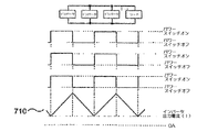
図7Bは本開示の実施例に基づいて負荷に対して電流を供給する3個の同期されたインバータの電流リップルの例示的グラフを示している。図7Bに示したグラフの実施例は単に例示的なものに過ぎない。本開示の範囲を逸脱すること無しにその他の実施例を使用することが可能である。 FIG. 7B shows an exemplary graph of the current ripple of three synchronized inverters supplying current to a load according to an embodiment of the present disclosure. The example graph shown in FIG. 7B is merely exemplary. Other embodiments may be used without departing from the scope of this disclosure.
1例においては、3個のパワーインバータが並列に接続されており、且つそれらのパワースイッチターンオン時間は1サイクル時間、即ちインバータスイッチング周波数の1周期、内において等しく離隔されている。任意の与えられた時間において、出力電流を増加させているか又は減少させているかのいずれかである2個のインバータが存在しており、一方3番目のインバータは該出力電流に対して反対のことを行っている。このことは、任意の時間において、出力電流におけるリップルは一つのインバータに対するのと同じ割合で上昇又は下降しているが、それが単一のインバータに対して行う時間の三分の一に対して上昇又は下降することを意味している。その結果は、鋸歯状波710形態のリップル電流であり、それはインバータスイッチング周波数の3倍であるが、単一のインバータに対するリップル電流705の振幅の三分の一である。該リップル電流の基本周波数の高調波の振幅も、それらが単一のインバータに対するものの三分の一である。 In one example, three power inverters are connected in parallel and their power switch turn-on times are equally spaced within one cycle time, ie, one period of the inverter switching frequency. There are two inverters that are either increasing or decreasing the output current at any given time, while the third inverter is the opposite of the output current It is carried out. This means that at any given time, the ripple in the output current rises or falls at the same rate as for one inverter, but for one-third of the time it does for a single inverter. It means to go up or down. The result is a ripple current in the form of a sawtooth 710, which is three times the inverter switching frequency, but one third of the amplitude of the ripple current 705 for a single inverter. The amplitude of the harmonics of the fundamental frequency of the ripple current is also one third of that for a single inverter.
図7Cは、本開示の実施例に基づいて負荷へ電流を供給する3個の調整されたインターリーブ型インバータに対する電流の例示的グラフを示している。図7Cに示したグラフの実施例は単に例示的なものに過ぎない。本開示の範囲を逸脱すること無しにその他の実施例を使用することが可能である。 FIG. 7C shows an exemplary graph of current for three regulated interleaved inverters supplying current to a load according to an embodiment of the present disclosure. The example graph shown in FIG. 7C is merely exemplary. Other embodiments may be used without departing from the scope of this disclosure.
幾つかの実施例において、該インバータは位相毎にインターリーブされている。この様な実施例においては、1個のインバータが2番目のインバータの前にターンオンされる。更に、該2番目のインバータの後の或る時間において3番目のインバータがターンオンされる。各インバータがターンオンされる間の間隔は、スイッチオン及びオフされるインバータの数に基づくものとすることが可能である。例えば、該間隔は負の20度(−20°)と正の20度(+20°)との間の位相シフトとすることが可能である。調整済みインターリービングは、ACパワーグリッドへ送られるAC出力における高調波を減少させるために、最大パワーポイント計算同期と関連して動作する。調整済みインターリービングは、図7Bにおける鋸歯状波710形態によって例示される建設的干渉ではなく各インバータから周波数の破壊的干渉を与える。従って、インターリーブされたインバータにより形成される鋸歯状波715形態は、図7Bに例示した同期型インバータのものよりも著しく一層小さなものであり、且つ、幾つかの実施例においては、図7Aに例示した単一インバータの鋸歯状リップル電流705よりも一層小さいものである。 In some embodiments, the inverters are interleaved phase by phase. In such an embodiment, one inverter is turned on before the second inverter. In addition, the third inverter is turned on at some time after the second inverter. The interval during which each inverter is turned on can be based on the number of inverters that are switched on and off. For example, the spacing can be a phase shift between negative 20 degrees (−20 °) and positive 20 degrees (+ 20 °). Adjusted interleaving operates in conjunction with maximum power point calculation synchronization to reduce harmonics in the AC output sent to the AC power grid. Adjusted interleaving provides destructive interference in frequency from each inverter rather than the constructive interference illustrated by the sawtooth 710 form in FIG. 7B. Thus, the sawtooth 715 form formed by the interleaved inverter is significantly smaller than that of the synchronous inverter illustrated in FIG. 7B and, in some embodiments, illustrated in FIG. 7A. This is even smaller than the sawtooth ripple current 705 of the single inverter.
図8は本開示の実施例に基づいて出力正弦波の高調波歪みに関する非調整型と調整型のインターリーブ型インバータの効果を示した例示的グラフを示している。図8に示したグラフの実施例は単に例示的なものに過ぎない。本開示の範囲を逸脱すること無しにその他の実施例を使用することが可能である。 FIG. 8 shows an exemplary graph illustrating the effect of unregulated and regulated interleaved inverters on harmonic distortion of the output sine wave according to an embodiment of the present disclosure. The example graph shown in FIG. 8 is merely illustrative. Other embodiments may be used without departing from the scope of this disclosure.
図8に示したグラフ表示は、AC正弦波の高調波成分に関する非調整型インバータと調整型インターリーブ型インバータの効果を比較している。上のグラフは2個及び3個の配列結合した非調整型インバータに対する出力電流の半分の正弦波を示している。上のグラフは、1個のインバータから並列の2個のインバータへそして並列の3個のインバータへ移行する場合に、正弦波に付加される鋸歯状電流リップルの振幅が漸次的に一層大きくなることを示している。 The graph display shown in FIG. 8 compares the effects of the non-adjustable inverter and the adjusted interleaved inverter on the harmonic component of the AC sine wave. The upper graph shows a sine wave at half the output current for two and three arrayed unregulated inverters. The graph above shows that the amplitude of the sawtooth current ripple added to the sine wave gradually increases when moving from one inverter to two parallel inverters and then to three parallel inverters. Is shown.
下のグラフは、2個及び3個の並列結合した調整型インターリーブ型インバータに対する出力電流の半分の正弦波を示している。理解されるように、2個及び3個の並列結合した調整型インターリーブ型インバータの例示は単に例示的なものに過ぎず、本開示の範囲を逸脱すること無しに3個を超えるインバータを使用することが可能である。調整型インターリーブ型インバータの場合には、正弦波に付加される鋸歯状電流リップルの振幅は、1個のインバータから並列の2個のインバータへそして並列の3個のインバータへ移行する場合に、周波数において漸次的に一層高いものとなり且つ振幅において一層小さなものとなる。 The lower graph shows a sine wave at half the output current for two and three parallel-coupled regulated interleaved inverters. As will be appreciated, the illustration of two and three parallel coupled regulated interleaved inverters is merely exemplary and uses more than three inverters without departing from the scope of the present disclosure. It is possible. In the case of a regulated interleaved inverter, the amplitude of the sawtooth current ripple added to the sine wave is the frequency when transitioning from one inverter to two parallel inverters and to three parallel inverters. Progressively higher and lower in amplitude.
調整型インターリービングは、並列の4個又はそれ以上のインバータへ拡張させることが可能である。調整型インターリービングの場合、N個の並列接続したインバータの内の1個における単に1個のインバータパワースイッチが、いずれかの時刻において、オフ状態からオン状態へ遷移するか、又はオン状態からオフ状態へ遷移する。連続的なパワースイッチ活性化(ターンオン)のオフ状態からオン状態への遷移はインバータスイッチング周波数をNで割り算した期間である。 Regulated interleaving can be extended to four or more inverters in parallel. In the case of regulated interleaving, only one inverter power switch in one of N parallel-connected inverters transitions from an off state to an on state at any time or off from an on state. Transition to the state. The transition from the OFF state to the ON state of continuous power switch activation (turn-on) is a period obtained by dividing the inverter switching frequency by N.
図9は本開示の実施例に基づく変圧器無しブースト無しDC・ACパワーインバータに対する概略図を例示している。図9に示したインバータの実施例は単に例示的なものに過ぎない。本開示の範囲を逸脱すること無しにその他の実施例を使用することが可能である。 FIG. 9 illustrates a schematic diagram for a transformerless boostless DC / AC power inverter according to an embodiment of the present disclosure. The inverter embodiment shown in FIG. 9 is merely exemplary. Other embodiments may be used without departing from the scope of this disclosure.
幾つかの実施例においては、インバータ900はDC電圧ブースト無しでDC入力からAC出力を発生することが可能である。従って、インバータ900は、従来のDC・ACパワー変換器と比較して効率の点において有益性を提供している。何故ならば、インバータ900は1個のスイッチング変換ステージを包含しているに過ぎないからである。
In some embodiments, the
幾つかのこの様な実施例において、パワースイッチ及び電流制限用インダクタがインバータ220内において一緒に接続されている。ソーラーアレイは多数のソーラーパネル905を包含している。ソーラーパネル905は、図1を参照して上に説明したソーラーパネル105と同じ構造及び形態のものとすることが可能である。
In some such embodiments, a power switch and a current limiting inductor are connected together in inverter 220. The solar array includes a number of
インバータ900は、正(+)のDCパワー入力線910と負(−)のDCパワー入力線912とを包含している。入力電流検知抵抗914が負DCパワー入力線912と接地916との間に結合されている。ノイズフィルタコンデンサ918が正DCパワー入力線910と負DCパワー入力線912との間に結合されている。正DCパワー入力線910は、更に、コンデンサ918の正リードが高側パワースイッチ920,922のドレインノードへ結合されるように、高側パワースイッチ920及び高側パワースイッチ922のドレインノードへ結合されている。パワースイッチ920のソースは第1フリーホイールダイオード924のカソード及び第1電流制限用インダクタ926の第1リードへ結合されている。第1フリーホイールダイオード924のアノードは接地916へ結合されている。第1電流制限用インダクタ926の第2リードは、第1プルダウンスイッチ928のドレイン、出力ノイズフィルタコンデンサ930の第1リード、AC出力「L」線932へ結合されている。パワースイッチ922のソースは、第2フリーホイールダイオード922のカソード及び第2電流制限用インダクタ936の第1リードへ結合されている。第2フリーホイールダイオード934のアノードは接地916へ結合されている。第2電流制限用インダクタ936の第2リードは、第2プルダウンスイッチ938のドレイン、出力ノイズフィルタコンデンサ930の第2リード、及びAC出力「N」線940へ結合されている。プルダウンスイッチ928,938のソースノードは互いに結合されており且つ出力電流検知抵抗942を介して孤立したパワー接地へ結合されている。インバータ900はインバータ制御器944を包含しており、該インバータ制御器944は、制御線945及び946上を第1制御信号をスイッチ920へ通信し、制御線948及び950上を第2制御信号をスイッチ928へ通信し、制御線952及び954上を第3制御信号をスイッチ938へ通信し、且つ制御線956及び958上を第4制御信号をスイッチ922へ通信する。
インバータ900は制御器944によって出力されるAC正弦波の正の半サイクル期間中に動作し、最初に、ライン(線)954と相対的にライン952上に正電圧を印加してスイッチ938をターンオンさせ、次いで、ライン946と相対的にライン945上にゼロボルトと正電圧との間で変化するパルス幅変調した方形波を印加させて絶えず変化するオン時間及び絶えず変化するオフ時間でパワースイッチ920を交互にターンオン及びターンオフさせる。
パワースイッチ920の絶えず変化するオン時間及びオフ時間は、平均出力電流が時間にわたり正の半分の正弦波の形状に追従するようにパワースイッチ920の一つのオン・オフサイクルにわたる量を変化させることにより、インダクタ926,936における出力電流をビルドアップさせるか又は減衰させる。プルダウンスイッチ938は正の半分の正弦波の全時間に対してオンのままであり且つプルダウンスイッチ928のターンオンと同時的にターンオフされる。AC正弦波の負の半分部分は正の半分部分と全く同じ態様で発生されるが、ライン950と相対的にライン948へ印加される正電圧によって負の半分の正弦波の全時間に対してスイッチ928がターンオンされる点が異なる。パワースイッチ922は、次いで、制御線958及び956上のパルス幅変調された方形波電圧によって交互にターンオン及びターンオフされて、出力電流を負の半分の正弦波の形状に追従させる(出力電流方向は逆にされる)。
The constantly changing on and off times of the
第1クランプダイオード960のアノードはスイッチ928のドレインへ結合されている。第1クランプダイオード960のカソードは正のDCパワー入力線910へ結合されている。第2クランプダイオード962のアノードはスイッチ938のドレインへ結合されており、且つ第2クランプダイオード962のカソードは正のDCパワー入力線910へ結合されている。
The anode of
入力検知抵抗914を横断しての電圧は入力電流を表しており且つライン(線)964によって制御器944へ結合されている。出力検知抵抗942を横断しての電圧は出力電流を表しており且つライン966によって制御器944へ結合されている。
The voltage across
図10は、本開示の実施例に基いて、3相ACパワー発生のために3相デルタ形態で結合されている複数のインバータグループを具備しているソーラーアレイの概略図を例示している。図10に示したソーラーアレイの実施例は、単に例示的なものに過ぎない。本開示の範囲を逸脱すること無しにその他の実施例を使用することが可能である。 FIG. 10 illustrates a schematic diagram of a solar array comprising a plurality of inverter groups coupled in a three-phase delta configuration for three-phase AC power generation, according to an embodiment of the present disclosure. The solar array embodiment shown in FIG. 10 is merely illustrative. Other embodiments may be used without departing from the scope of this disclosure.
幾つかの実施例において、付加的な調整処理が、複数のインバータからなる複数のグループ1002,1004,1006が3相デルタ形態に結合されている場合にワイアレスデータネットワークによって実施される。該ワイアレスデータネットワークは遠隔制御器(図6を参照して上に詳細に説明した)を包含しており、グループ制御器1022,1024,1026は適応的パワーファクタ及び位相平衡化を実施する。
In some embodiments, additional adjustment processing is performed by the wireless data network when
適応的パワーファクタ及び位相平衡化は以下の如くに動作する。全インストレーション(例えば、ソーラーサイト)に対するAC出力メーター1010が、他の位相の正弦波に対して一つの位相の過剰な電圧正弦波タイミングシフトを検知するか、又は一つの位相に関して電圧と電流との間の過剰な正弦波タイミングシフトを検知する場合には、AC出力メーター1010はこの問題に関する情報をワイアレストランシーバ1032及びアンテナ1034を介してワイアレスネットワーク上を全てのグループ制御器1022,1024,1026へ送信する。グループ制御器は情報を受信し且つ送信するためにトランシーバ及びアンテナを包含している。例えば、グループ制御器1022は、トランシーバ及びアンテナ1023を包含しており、グループ制御器1024はトランシーバ及びアンテナ1025を包含しており、且つグループ制御器127。グループ制御器1022,1024,1026は、夫々、LAN接続1040,1042,1044を介してそれらの夫々のインバータ1011−1019に信号を送って全ての位相の正弦波タイミングを正常な3相タイミングに合致させる。
Adaptive power factor and phase balancing operates as follows. The
最後に、インバータグループ1002,1004,1006のLAN接続1040,1042,1044、ワイアレスデータネットワーク、及びインターネット(又はその他のデータワイアライン)接続を具備するワイアレスルータが、ソーラーパネルセンサー、パワーインバータ1011−1019及びACメーター1010によって回収されたデータを、ソーラーアレイインストレーションの機能を解析し且つ該インストレーションにおける問題及び障害に関してシステムオペレータに対して警告を与えるために、遠隔制御器へ転送させることを可能とさせる。インバータグループ1002,1004,1006内のいずれかのインバータ1011−1019に障害が発生すると、グループ制御器1022,1024,1026が、他のものに影響を与えること無しに、そのインバータをシャットダウンさせる。その後に、残りのインバータが負荷を担うこととなる。次いで、グループ制御器1022,1024,1026は、ワイアレスデータネットワーク、ワイアレスルータ、及びインターネットを介してアラート即ち警告を遠隔制御器へ送ってその障害に関してシステムオペレータに報告する。
Finally, wireless routers with
付加的に且つ代替的に、インバータグループ1002,1004,1006内のいずれかのインバータ1011−1019がスレッシュホールド値を超える内部温度を有している場合には、そのインバータは出力パワー制限モードに移行し、且つそのグループ内の他のインバータは失われたパワーを補うためにより多くのパワーを発生する。グループ制御器1022,1024,1026は、又、この条件に対しても遠隔制御器に対してアラートを送る。
Additionally and alternatively, if any inverter 1011-1019 in the
付加的な且つ代替的な実施例において、DC・ACインバータは、インバータパワースイッチの可変周波数スイッチングとして知られている内部効率最適化方法を実施する形態とされている制御器を包含している。該制御器は、インバータ動作を調整するためにインバータ間にデータリンクを必要とする前述した最適化方法とは独立した可変周波数スイッチングを実施することが可能である。スイッチング周波数としても知られているインバータパワースイッチ周波数は、典型的に、約20kHzに設定される。スイッチング周波数が20kHzよりも一層高くなると、一層小型のコンポーネントを使用することが可能である。何故ならば、各PWMサイクルにおいて転送されるパワーは一層小さいからである。一層小さなコンポーネントは一層低い製品コストとなる。然しながら、スイッチング周波数が上昇するに従い、スイッチング損失も増加し且つパワー変換効率は低下する。代替的に、スイッチング周波数が低下すると、スイッチング損失は低下し且つパワー変換効率は上昇する。 In an additional and alternative embodiment, the DC / AC inverter includes a controller configured to implement an internal efficiency optimization method known as variable frequency switching of the inverter power switch. The controller can perform variable frequency switching independent of the previously described optimization method that requires a data link between inverters to coordinate inverter operation. The inverter power switch frequency, also known as the switching frequency, is typically set to about 20 kHz. If the switching frequency is much higher than 20 kHz, smaller components can be used. This is because less power is transferred in each PWM cycle. Smaller components result in lower product costs. However, as the switching frequency increases, the switching loss increases and the power conversion efficiency decreases. Alternatively, as the switching frequency decreases, the switching loss decreases and the power conversion efficiency increases.
更に付加的な且つ代替的な実施例において、インバータは連続導通モード(CCM)に動作を維持するための形態とされている。インバータは2つの動作モードで動作し、即ち、CCMと非連続導通モード(DCM)である。CCMにおいては、インダクタ電流は決して0に到達することはない。DCMにおいては、インダクタ電流は0に到達する。効率的な動作のためには、インバータはCCMモードにおいてのみ動作する形態とされる。CCMモードにおける動作を維持しながら、正弦波のピーク出力パワー間隔期間中のスイッチング損失を減少させるためのインバータにおける主要な制御は、変化する電圧及び電流に応答してのスイッチング周波数の調節である。従って、出力電圧及びパワーが正弦波信号における最大に近づくに従い、スイッチング周波数を下方向へ調節して最大パワー転送期間中におけるスイッチング損失を最小化させる。次いで、正弦波出力が低出力電圧及びパワーに近づくに従い、該インダクタを介しての電流がゼロへ減少しないようにスイッチング周波数を一層高い周波数へ増加させることが可能である。 In yet additional and alternative embodiments, the inverter is configured to maintain operation in continuous conduction mode (CCM). The inverter operates in two modes of operation: CCM and discontinuous conduction mode (DCM). In CCM, the inductor current never reaches zero. In DCM, the inductor current reaches zero. For efficient operation, the inverter is configured to operate only in the CCM mode. The primary control in the inverter to reduce switching losses during the sinusoidal peak output power interval while maintaining operation in the CCM mode is adjustment of the switching frequency in response to changing voltage and current. Therefore, as the output voltage and power approach the maximum in the sinusoidal signal, the switching frequency is adjusted downward to minimize switching losses during the maximum power transfer period. The switching frequency can then be increased to a higher frequency so that the current through the inductor does not decrease to zero as the sine wave output approaches low output voltage and power.
本開示を例示的実施例について説明したが、種々の変更及び修正が当業者に対して示唆されている場合がある。本開示はこの様な変更及び修正も特許請求の範囲内に入るものであることが意図されている。 Although this disclosure has been described with reference to exemplary embodiments, various changes and modifications may be suggested to one skilled in the art. The present disclosure is intended to embrace such changes and modifications as fall within the scope of the appended claims.
Claims (24)
複数個のインバータが直流エネルギを受け取り且つ交流エネルギを出力すべく適合されており、第1インバータの出力が第2インバータの出力とインターリーブされているシステム。 In an energy conversion array for use in an energy generation system,
A system in which a plurality of inverters are adapted to receive DC energy and output AC energy, and the output of the first inverter is interleaved with the output of the second inverter.
複数個のインテリジェントインバータが直流エネルギを受け取り且つ交流エネルギを出力すべく適合されており、該複数個のインバータはパワー帯域最適化を実施する形態とされているアレイ。 In an energy conversion array for use in an energy generation system,
An array in which a plurality of intelligent inverters are adapted to receive DC energy and output AC energy, the plurality of inverters being configured to perform power band optimization.
該複数個のインバータのパワー出力を測定し、
該測定したパワーを最適パワー帯域の上側限界と該最適パワー帯域の下側限界の内の少なくとも一つと比較し、
該測定したパワーが該上側限界を超えていることの判別に応答して少なくとも1個の付加的なインバータをイネーブルさせ、
該測定したパワーが該下側限界よりも一層低いことの判別に応答して少なくとも1個のインバータをディスエーブルさせる、
形態とされているアレイ。 The group controller according to claim 3, further comprising a group controller,
Measuring the power output of the plurality of inverters;
Comparing the measured power with at least one of the upper limit of the optimum power band and the lower limit of the optimum power band;
Enabling at least one additional inverter in response to determining that the measured power exceeds the upper limit;
Disabling at least one inverter in response to determining that the measured power is lower than the lower limit;
An array in the form.
複数個のソーラーパワー発生装置、
各インバータが該複数個のソーラーパワー発生装置の内の一つから直流エネルギを受け取り且つ交流エネルギを出力すべく適合されている複数個のインバータ、
を有しており、第1インバータの出力が第2インバータの出力とインターリーブされているアレイ。 In an energy conversion array for use in an energy generation system,
Multiple solar power generators,
A plurality of inverters, each inverter being adapted to receive DC energy from one of the plurality of solar power generators and output AC energy;
And the output of the first inverter is interleaved with the output of the second inverter.
複数個のソーラーパワー発生装置、
該複数個のソーラーパワー発生装置へ結合されており、非規制直流エネルギを受け取り且つ交流エネルギの出力を調整する形態とされている複数個のインバータ、
を有しているアレイ。 In energy conversion arrays used in solar power systems,
Multiple solar power generators,
A plurality of inverters coupled to the plurality of solar power generators, configured to receive non-regulated DC energy and to regulate the output of AC energy;
Having an array.
該複数個のインバータのパワー出力を測定し、
該測定したパワーを最適パワー帯域の上側限界及び該最適パワー帯域の下側限界の内の少なくとも一つと比較し、
該測定したパワーが該上側限界を超えることの判別に応答して少なくとも1個の付加的なインバータをイネーブルし、
該測定したパワーが該下側限界より一層低いことの判別に応答して少なくとも1個のインバータをディスエーブルする、
形態とされているアレイ。 The controller of claim 10, wherein the plurality of controllers are
Measuring the power output of the plurality of inverters;
Comparing the measured power with at least one of the upper limit of the optimum power band and the lower limit of the optimum power band;
Enabling at least one additional inverter in response to determining that the measured power exceeds the upper limit;
Disabling at least one inverter in response to determining that the measured power is lower than the lower limit;
An array in the form.
複数個のエネルギ発生装置からの電気的エネルギを複数個のインバータによって受け取り、
該複数個のインバータによる直流エネルギの交流エネルギへの変換を実施するために該複数個のインバータのスイッチングを調整する、
ことを包含している方法。 In the current conversion method for power array,
Electrical energy from a plurality of energy generators is received by a plurality of inverters;
Adjusting the switching of the plurality of inverters to perform conversion of DC energy to AC energy by the plurality of inverters;
The method that encompasses that.
該複数個のインバータの出力パワーを測定し、
該測定したパワーを最適パワー帯域の上側限界及び該最適パワー帯域の下側限界の内の少なくとも一つと比較し、
該測定したパワーが該上側限界を超えていることの判別に応答して少なくとも1個の付加的なインバータをイネーブルし、
該測定したパワーが該下側限界より一層低いことの判別に応答して少なくとも1個のインバータをディスエーブルする、
方法。 In claim 18, when adjusting,
Measuring the output power of the plurality of inverters;
Comparing the measured power with at least one of the upper limit of the optimum power band and the lower limit of the optimum power band;
Enabling at least one additional inverter in response to determining that the measured power exceeds the upper limit;
Disabling at least one inverter in response to determining that the measured power is lower than the lower limit;
Method.
Applications Claiming Priority (3)
| Application Number | Priority Date | Filing Date | Title |
|---|---|---|---|
| US12777208P | 2008-05-14 | 2008-05-14 | |
| US61/127,772 | 2008-05-14 | ||
| PCT/US2009/044033 WO2009140548A2 (en) | 2008-05-14 | 2009-05-14 | System and method for an array of intelligent inverters |
Publications (2)
| Publication Number | Publication Date |
|---|---|
| JP2011522505A true JP2011522505A (en) | 2011-07-28 |
| JP2011522505A5 JP2011522505A5 (en) | 2012-07-05 |
Family
ID=41314983
Family Applications (1)
| Application Number | Title | Priority Date | Filing Date |
|---|---|---|---|
| JP2011509720A Pending JP2011522505A (en) | 2008-05-14 | 2009-05-14 | System and method for an array of multiple intelligent inverters |
Country Status (7)
| Country | Link |
|---|---|
| US (1) | US20090283129A1 (en) |
| EP (1) | EP2291908A4 (en) |
| JP (1) | JP2011522505A (en) |
| KR (1) | KR20110014200A (en) |
| CN (1) | CN102067429A (en) |
| TW (1) | TW201014146A (en) |
| WO (1) | WO2009140548A2 (en) |
Cited By (2)
| Publication number | Priority date | Publication date | Assignee | Title |
|---|---|---|---|---|
| CN113328637A (en) * | 2021-06-01 | 2021-08-31 | 浙江大学 | Distributed large-current power supply system based on group cooperative control of industrial Internet |
| US11264917B2 (en) | 2019-12-12 | 2022-03-01 | Kohler Co. | Interleaved inverter |
Families Citing this family (156)
| Publication number | Priority date | Publication date | Assignee | Title |
|---|---|---|---|---|
| US10693415B2 (en) | 2007-12-05 | 2020-06-23 | Solaredge Technologies Ltd. | Testing of a photovoltaic panel |
| US11881814B2 (en) | 2005-12-05 | 2024-01-23 | Solaredge Technologies Ltd. | Testing of a photovoltaic panel |
| US8816535B2 (en) | 2007-10-10 | 2014-08-26 | Solaredge Technologies, Ltd. | System and method for protection during inverter shutdown in distributed power installations |
| US8013472B2 (en) | 2006-12-06 | 2011-09-06 | Solaredge, Ltd. | Method for distributed power harvesting using DC power sources |
| US11855231B2 (en) | 2006-12-06 | 2023-12-26 | Solaredge Technologies Ltd. | Distributed power harvesting systems using DC power sources |
| US11296650B2 (en) | 2006-12-06 | 2022-04-05 | Solaredge Technologies Ltd. | System and method for protection during inverter shutdown in distributed power installations |
| US9112379B2 (en) | 2006-12-06 | 2015-08-18 | Solaredge Technologies Ltd. | Pairing of components in a direct current distributed power generation system |
| US9130401B2 (en) | 2006-12-06 | 2015-09-08 | Solaredge Technologies Ltd. | Distributed power harvesting systems using DC power sources |
| US8618692B2 (en) | 2007-12-04 | 2013-12-31 | Solaredge Technologies Ltd. | Distributed power system using direct current power sources |
| US8319471B2 (en) | 2006-12-06 | 2012-11-27 | Solaredge, Ltd. | Battery power delivery module |
| US9088178B2 (en) | 2006-12-06 | 2015-07-21 | Solaredge Technologies Ltd | Distributed power harvesting systems using DC power sources |
| US8963369B2 (en) | 2007-12-04 | 2015-02-24 | Solaredge Technologies Ltd. | Distributed power harvesting systems using DC power sources |
| US11309832B2 (en) | 2006-12-06 | 2022-04-19 | Solaredge Technologies Ltd. | Distributed power harvesting systems using DC power sources |
| US8384243B2 (en) | 2007-12-04 | 2013-02-26 | Solaredge Technologies Ltd. | Distributed power harvesting systems using DC power sources |
| US8947194B2 (en) | 2009-05-26 | 2015-02-03 | Solaredge Technologies Ltd. | Theft detection and prevention in a power generation system |
| US11569659B2 (en) | 2006-12-06 | 2023-01-31 | Solaredge Technologies Ltd. | Distributed power harvesting systems using DC power sources |
| US11687112B2 (en) | 2006-12-06 | 2023-06-27 | Solaredge Technologies Ltd. | Distributed power harvesting systems using DC power sources |
| US11728768B2 (en) | 2006-12-06 | 2023-08-15 | Solaredge Technologies Ltd. | Pairing of components in a direct current distributed power generation system |
| US11735910B2 (en) | 2006-12-06 | 2023-08-22 | Solaredge Technologies Ltd. | Distributed power system using direct current power sources |
| US8319483B2 (en) | 2007-08-06 | 2012-11-27 | Solaredge Technologies Ltd. | Digital average input current control in power converter |
| US8473250B2 (en) | 2006-12-06 | 2013-06-25 | Solaredge, Ltd. | Monitoring of distributed power harvesting systems using DC power sources |
| US11888387B2 (en) | 2006-12-06 | 2024-01-30 | Solaredge Technologies Ltd. | Safety mechanisms, wake up and shutdown methods in distributed power installations |
| WO2011019936A1 (en) | 2009-08-14 | 2011-02-17 | Newdoll Enterprises Llc | Enhanced solar panels, liquid delivery systems and associated processes for solar energy systems |
| US7772716B2 (en) | 2007-03-27 | 2010-08-10 | Newdoll Enterprises Llc | Distributed maximum power point tracking system, structure and process |
| US9196770B2 (en) | 2007-03-27 | 2015-11-24 | Newdoll Enterprises Llc | Pole-mounted power generation systems, structures and processes |
| EP3324505B1 (en) | 2007-10-15 | 2023-06-07 | Ampt, Llc | Systems for highly efficient solar power |
| US7919953B2 (en) | 2007-10-23 | 2011-04-05 | Ampt, Llc | Solar power capacitor alternative switch circuitry system for enhanced capacitor life |
| DE102007054647A1 (en) * | 2007-11-15 | 2009-06-18 | Siemens Ag | Solar inverter with several parallel single inverters and with a higher-level electronic control unit |
| US8294451B2 (en) * | 2007-12-03 | 2012-10-23 | Texas Instruments Incorporated | Smart sensors for solar panels |
| US11264947B2 (en) | 2007-12-05 | 2022-03-01 | Solaredge Technologies Ltd. | Testing of a photovoltaic panel |
| EP2232690B1 (en) | 2007-12-05 | 2016-08-31 | Solaredge Technologies Ltd. | Parallel connected inverters |
| US8049523B2 (en) | 2007-12-05 | 2011-11-01 | Solaredge Technologies Ltd. | Current sensing on a MOSFET |
| US9291696B2 (en) | 2007-12-05 | 2016-03-22 | Solaredge Technologies Ltd. | Photovoltaic system power tracking method |
| CN101933209B (en) | 2007-12-05 | 2015-10-21 | 太阳能安吉有限公司 | Release mechanism in distributed electrical power apparatus, to wake up and method for closing |
| WO2009118682A2 (en) | 2008-03-24 | 2009-10-01 | Solaredge Technolgies Ltd. | Zero current switching |
| US8037327B2 (en) * | 2008-03-31 | 2011-10-11 | Agilent Technologies, Inc. | System and method for improving dynamic response in a power supply |
| US8289183B1 (en) | 2008-04-25 | 2012-10-16 | Texas Instruments Incorporated | System and method for solar panel array analysis |
| WO2009136358A1 (en) | 2008-05-05 | 2009-11-12 | Solaredge Technologies Ltd. | Direct current power combiner |
| US7969133B2 (en) | 2008-05-14 | 2011-06-28 | National Semiconductor Corporation | Method and system for providing local converters to provide maximum power point tracking in an energy generating system |
| US8279644B2 (en) * | 2008-05-14 | 2012-10-02 | National Semiconductor Corporation | Method and system for providing maximum power point tracking in an energy generating system |
| US7991511B2 (en) * | 2008-05-14 | 2011-08-02 | National Semiconductor Corporation | Method and system for selecting between centralized and distributed maximum power point tracking in an energy generating system |
| US9077206B2 (en) | 2008-05-14 | 2015-07-07 | National Semiconductor Corporation | Method and system for activating and deactivating an energy generating system |
| US8139382B2 (en) * | 2008-05-14 | 2012-03-20 | National Semiconductor Corporation | System and method for integrating local maximum power point tracking into an energy generating system having centralized maximum power point tracking |
| US7962249B1 (en) * | 2008-05-14 | 2011-06-14 | National Semiconductor Corporation | Method and system for providing central control in an energy generating system |
| US10153383B2 (en) * | 2008-11-21 | 2018-12-11 | National Semiconductor Corporation | Solar string power point optimization |
| US20100156188A1 (en) * | 2008-12-24 | 2010-06-24 | Fishman Oleg S | Solar Photovoltaic Power Collection via High Voltage, Direct Current Systems with Conversion and Supply to an Alternating Current Transmission Network |
| US8212408B2 (en) * | 2008-12-24 | 2012-07-03 | Alencon Acquisition Co., Llc. | Collection of electric power from renewable energy sources via high voltage, direct current systems with conversion and supply to an alternating current transmission network |
| FI122046B (en) * | 2009-01-12 | 2011-07-29 | Abb Oy | solar power plants |
| EP2219276B1 (en) * | 2009-02-11 | 2015-12-02 | SMA Solar Technology AG | Photovoltaic assembly for three-phase feeding into an electric energy supply network |
| WO2010114995A1 (en) | 2009-04-01 | 2010-10-07 | Nextronex Energy Systems, Llc | A grid tie solar system and a method |
| WO2010120315A1 (en) | 2009-04-17 | 2010-10-21 | Ampt, Llc | Methods and apparatus for adaptive operation of solar power systems |
| WO2010121181A2 (en) * | 2009-04-17 | 2010-10-21 | National Semiconductor Corporation | System and method for over-voltage protection in a photovoltaic system |
| WO2010121211A2 (en) | 2009-04-17 | 2010-10-21 | National Semiconductor Corporation | System and method for over-voltage protection of a photovoltaic system with distributed maximum power point tracking |
| US20100288327A1 (en) * | 2009-05-13 | 2010-11-18 | National Semiconductor Corporation | System and method for over-Voltage protection of a photovoltaic string with distributed maximum power point tracking |
| CN104158483B (en) | 2009-05-22 | 2017-09-12 | 太阳能安吉科技有限公司 | The heat dissipating junction box of electric isolution |
| US20100300509A1 (en) * | 2009-05-26 | 2010-12-02 | Douglas William Raymond | Solar photovoltaic modules with integral wireless telemetry |
| US8954203B2 (en) * | 2009-06-24 | 2015-02-10 | Tigo Energy, Inc. | Systems and methods for distributed power factor correction and phase balancing |
| US20160065127A1 (en) | 2009-08-14 | 2016-03-03 | Newdoll Enterprises Llc | Enhanced solar panels, liquid delivery systems and associated processes for solar energy systems |
| US9200818B2 (en) | 2009-08-14 | 2015-12-01 | Newdoll Enterprises Llc | Enhanced solar panels, liquid delivery systems and associated processes for solar energy systems |
| US8874277B2 (en) * | 2009-09-15 | 2014-10-28 | Denis Kouroussis | Smart-grid adaptive power management method and system with power factor optimization and total harmonic distortion reduction |
| US20110084646A1 (en) * | 2009-10-14 | 2011-04-14 | National Semiconductor Corporation | Off-grid led street lighting system with multiple panel-storage matching |
| US20110088743A1 (en) * | 2009-10-15 | 2011-04-21 | Yuhao Luo | Method to manage a photovoltaic system |
| WO2011049985A1 (en) | 2009-10-19 | 2011-04-28 | Ampt, Llc | Novel solar panel string converter topology |
| JP2011120449A (en) * | 2009-10-29 | 2011-06-16 | Sanyo Electric Co Ltd | Power generation system, control device, and switching circuit |
| US8421400B1 (en) | 2009-10-30 | 2013-04-16 | National Semiconductor Corporation | Solar-powered battery charger and related system and method |
| DE202009016164U1 (en) * | 2009-11-26 | 2010-03-04 | Carlo Gavazzi Services Ag | Control device for photovoltaic modules |
| FR2953996B1 (en) * | 2009-12-11 | 2012-01-20 | Centre Nat Rech Scient | ELECTRONIC MANAGEMENT SYSTEM OF PHOTOVOLTAIC CELLS FUNCTION OF METEOROLOGY |
| FR2953997B1 (en) | 2009-12-11 | 2012-01-20 | Centre Nat Rech Scient | SYSTEM FOR ELECTRONIC MANAGEMENT OF PHOTOVOLTAIC CELLS WITH ADJUSTABLE THRESHOLDS |
| TW201123670A (en) * | 2009-12-23 | 2011-07-01 | Univ Nat Taiwan | Solar electric power generation system and monitoring method of the same |
| US20110224839A1 (en) * | 2010-03-11 | 2011-09-15 | Christopher Thompson | Power Point Tracking |
| US9502904B2 (en) | 2010-03-23 | 2016-11-22 | Eaton Corporation | Power conversion system and method providing maximum efficiency of power conversion for a photovoltaic system, and photovoltaic system employing a photovoltaic array and an energy storage device |
| DE102010016138A1 (en) * | 2010-03-25 | 2011-09-29 | Refu Elektronik Gmbh | Solar inverter for extended irradiation value range and operating method |
| US8853886B2 (en) | 2010-06-09 | 2014-10-07 | Tigo Energy, Inc. | System for use of static inverters in variable energy generation environments |
| US8513833B2 (en) * | 2010-06-20 | 2013-08-20 | Hewlett-Packard Development Company, L.P. | Circuit limiting an absolute voltage difference between electrical paths of photovoltaic dies |
| DE102010036816A1 (en) * | 2010-08-03 | 2012-02-09 | Newtos Ag | Method and device for monitoring and controlling a photovoltaic system |
| US20120049635A1 (en) * | 2010-08-27 | 2012-03-01 | General Electric Company | Solar power generation system and method |
| WO2012048012A2 (en) * | 2010-10-05 | 2012-04-12 | Alencon Systems, Inc. | High voltage energy harvesting and conversion renewable energy utility size electric power systems and visual monitoring and control systems for said systems |
| GB2485335B (en) * | 2010-10-25 | 2012-10-03 | Enecsys Ltd | Renewable energy monitoring system |
| US10230310B2 (en) | 2016-04-05 | 2019-03-12 | Solaredge Technologies Ltd | Safety switch for photovoltaic systems |
| US10673222B2 (en) | 2010-11-09 | 2020-06-02 | Solaredge Technologies Ltd. | Arc detection and prevention in a power generation system |
| GB2485527B (en) | 2010-11-09 | 2012-12-19 | Solaredge Technologies Ltd | Arc detection and prevention in a power generation system |
| US10673229B2 (en) | 2010-11-09 | 2020-06-02 | Solaredge Technologies Ltd. | Arc detection and prevention in a power generation system |
| CN102005953B (en) * | 2010-11-17 | 2012-08-08 | 特变电工新疆新能源股份有限公司 | Grid-connected inverter and alternating-current output filter method thereof |
| US9118213B2 (en) | 2010-11-24 | 2015-08-25 | Kohler Co. | Portal for harvesting energy from distributed electrical power sources |
| GB2486408A (en) | 2010-12-09 | 2012-06-20 | Solaredge Technologies Ltd | Disconnection of a string carrying direct current |
| US8155899B2 (en) * | 2010-12-16 | 2012-04-10 | Gregory Smith | Efficiency meter for photovoltaic power generation systems |
| KR101191214B1 (en) | 2010-12-28 | 2012-10-15 | 엘지전자 주식회사 | Photovoltaic power generation system |
| GB2483317B (en) | 2011-01-12 | 2012-08-22 | Solaredge Technologies Ltd | Serially connected inverters |
| US7977818B1 (en) | 2011-01-25 | 2011-07-12 | Wahl Eric R | Safety device for plug and play solar energy system |
| TWI447339B (en) | 2011-01-27 | 2014-08-01 | Univ Nat Central | Sun tracking method and sun tracking system |
| CN102624274A (en) * | 2011-01-30 | 2012-08-01 | 上海康威特吉能源技术有限公司 | Interleaving parallel grid-connected inverter and control method thereof |
| US8686332B2 (en) | 2011-03-07 | 2014-04-01 | National Semiconductor Corporation | Optically-controlled shunt circuit for maximizing photovoltaic panel efficiency |
| KR101296812B1 (en) * | 2011-06-08 | 2013-08-14 | 한국전기연구원 | System for examination of grid connected system and method for it |
| US9059604B2 (en) * | 2011-06-27 | 2015-06-16 | Sunpower Corporation | Methods and apparatus for controlling operation of photovoltaic power plants |
| US8774974B2 (en) * | 2011-07-15 | 2014-07-08 | First Solar, Inc. | Real-time photovoltaic power plant control system |
| CN102255536B (en) * | 2011-07-18 | 2013-06-05 | 浙江昱能光伏科技集成有限公司 | Solar photovoltaic three-phase micro-inverter system and method for promoting conversion efficiency thereof |
| US8941956B2 (en) * | 2011-07-26 | 2015-01-27 | Railpower, Llc | Switching ground tether circuit |
| US8570005B2 (en) | 2011-09-12 | 2013-10-29 | Solaredge Technologies Ltd. | Direct current link circuit |
| US8284574B2 (en) * | 2011-10-17 | 2012-10-09 | Solarbridge Technologies, Inc. | Method and apparatus for controlling an inverter using pulse mode control |
| US8982591B2 (en) | 2011-10-18 | 2015-03-17 | Tigo Energy, Inc. | System and method for exchangeable capacitor modules for high power inverters and converters |
| US9680301B2 (en) | 2011-10-27 | 2017-06-13 | Sunpower Corporation | Master-slave architecture for controlling operation of photovoltaic power plants |
| KR101272059B1 (en) * | 2011-10-31 | 2013-06-07 | 강문수 | A transformer matched parallel inverter for wide area multi-string solar power generation system |
| GB2497275A (en) * | 2011-11-25 | 2013-06-12 | Enecsys Ltd | Modular adjustable power factor renewable energy inverter system |
| FR2983363B1 (en) * | 2011-11-28 | 2014-07-25 | Schneider Electric Ind Sas | METHOD AND SYSTEM FOR DYNAMICALLY MANAGING AN ELECTRICITY DISTRIBUTION NETWORK |
| JP6003048B2 (en) * | 2011-11-29 | 2016-10-05 | ソニー株式会社 | Power generator |
| US20130155738A1 (en) * | 2011-12-19 | 2013-06-20 | General Electric Company | System and method for controlling reactive power in a power conversion system |
| KR101141074B1 (en) * | 2012-02-02 | 2012-05-03 | 주식회사 케이디파워 | Photovoltaic power generation system include multi-inverter |
| GB2498365A (en) | 2012-01-11 | 2013-07-17 | Solaredge Technologies Ltd | Photovoltaic module |
| US9853565B2 (en) | 2012-01-30 | 2017-12-26 | Solaredge Technologies Ltd. | Maximized power in a photovoltaic distributed power system |
| GB2498790A (en) | 2012-01-30 | 2013-07-31 | Solaredge Technologies Ltd | Maximising power in a photovoltaic distributed power system |
| GB2498791A (en) | 2012-01-30 | 2013-07-31 | Solaredge Technologies Ltd | Photovoltaic panel circuitry |
| EP2815283A4 (en) * | 2012-02-15 | 2015-08-26 | Gear Llc E | Electrical combiner box with improved functionality |
| GB2499991A (en) | 2012-03-05 | 2013-09-11 | Solaredge Technologies Ltd | DC link circuit for photovoltaic array |
| CN104272128B (en) * | 2012-05-29 | 2016-11-09 | 优信电子(香港)有限公司 | Solar power generation monitors method and the solar power generation monitoring system using in the method |
| US10115841B2 (en) | 2012-06-04 | 2018-10-30 | Solaredge Technologies Ltd. | Integrated photovoltaic panel circuitry |
| US9502902B2 (en) | 2012-06-26 | 2016-11-22 | Solarcity Corporation | System, method and apparatus for generating layout of devices in solar installations |
| CN102761283B (en) * | 2012-06-27 | 2015-11-25 | 华为技术有限公司 | Inverter control method, device and inverter |
| US9608438B2 (en) | 2012-07-17 | 2017-03-28 | Electronics And Telecommunications Research Institute | Inverter system for photovoltaic power generation |
| KR101395514B1 (en) * | 2012-11-26 | 2014-05-14 | 서울대학교산학협력단 | Grid-connected single-phase inverter for independent mppt and a method for controlling the inverter |
| US9548619B2 (en) | 2013-03-14 | 2017-01-17 | Solaredge Technologies Ltd. | Method and apparatus for storing and depleting energy |
| US9941813B2 (en) | 2013-03-14 | 2018-04-10 | Solaredge Technologies Ltd. | High frequency multi-level inverter |
| US9397497B2 (en) | 2013-03-15 | 2016-07-19 | Ampt, Llc | High efficiency interleaved solar power supply system |
| EP3506370B1 (en) | 2013-03-15 | 2023-12-20 | Solaredge Technologies Ltd. | Bypass mechanism |
| US9882507B2 (en) | 2013-04-16 | 2018-01-30 | Solarcity Corporation | Power factor adjustment in multi-phase power system |
| CZ2013311A3 (en) * | 2013-04-25 | 2014-06-04 | Unites Systems A.S. | System for managing electric power produced by photovoltaic cells |
| US9742188B2 (en) * | 2013-06-26 | 2017-08-22 | Energy Development Llc | System and method for installing solar panels based on number of panels and output of panels |
| TWI505598B (en) * | 2013-08-23 | 2015-10-21 | Ablerex Electronics Co Letd | Shadowing compensation device for solar cell modular |
| JP6163558B2 (en) * | 2013-08-27 | 2017-07-12 | 東芝三菱電機産業システム株式会社 | Solar power system |
| EP3050189A1 (en) * | 2013-09-26 | 2016-08-03 | Vestas Wind Systems A/S | Power conversion system with re-configurable power flow |
| KR102205161B1 (en) | 2014-01-15 | 2021-01-19 | 엘지전자 주식회사 | Power converting apparatus, and photovoltaic module |
| CN103825479A (en) * | 2014-02-20 | 2014-05-28 | 华为技术有限公司 | Power converter |
| US9318974B2 (en) | 2014-03-26 | 2016-04-19 | Solaredge Technologies Ltd. | Multi-level inverter with flying capacitor topology |
| CN104167761B (en) * | 2014-08-15 | 2017-04-19 | 江苏兆伏新能源有限公司 | Photovoltaic inverter power generation system and control method |
| TWI514714B (en) * | 2014-12-09 | 2015-12-21 | Univ Nat Cheng Kung | Distributed solar power system and controlling method thereof |
| CN104538987B (en) * | 2014-12-31 | 2017-01-11 | 阳光电源股份有限公司 | Control method and system for parallel connection of alternating current sides of photovoltaic inverters |
| CN204578425U (en) * | 2015-05-05 | 2015-08-19 | 无锡联动太阳能科技有限公司 | Novel solar power system |
| TWI566514B (en) * | 2015-05-11 | 2017-01-11 | 茂勝開發股份有限公司 | System and method applied to monitoring direct-current power of a photovoltaic generation module |
| US9887581B2 (en) * | 2015-05-15 | 2018-02-06 | Solarcity Corporation | Connectivity in an energy generation network |
| TWI573385B (en) * | 2015-12-18 | 2017-03-01 | 國立勤益科技大學 | Real-time fault detector of photovoltaic module array and method thereof |
| US10566798B2 (en) * | 2016-03-31 | 2020-02-18 | Texas Instruments Incorporated | Solar panel disconnect and reactivation system |
| US11018623B2 (en) | 2016-04-05 | 2021-05-25 | Solaredge Technologies Ltd. | Safety switch for photovoltaic systems |
| US11177663B2 (en) | 2016-04-05 | 2021-11-16 | Solaredge Technologies Ltd. | Chain of power devices |
| US10483759B2 (en) | 2016-04-07 | 2019-11-19 | Alencon Acquisition Co., Llc | Integrated multi-mode large-scale electric power support system for an electrical grid |
| JP6681476B2 (en) * | 2016-10-05 | 2020-04-15 | 株式会社日立製作所 | Power converter and power converter control method |
| US10488879B2 (en) | 2017-03-09 | 2019-11-26 | Ecole Polytechnique Federale De Lausanne (Epfl) | Device and method for performing maximum power point tracking for photovoltaic devices in presence of hysteresis |
| US10554149B2 (en) * | 2017-11-20 | 2020-02-04 | Solaredge Technologies Ltd. | Providing positional awareness information and increasing power quality of parallel connected inverters |
| TWI658687B (en) * | 2018-03-14 | 2019-05-01 | 財團法人工業技術研究院 | Dc-to-ac converter and control method thereof |
| US10516271B2 (en) * | 2018-06-29 | 2019-12-24 | LT Lighting (Taiwan) Corp. | Single-phase energy utilization tracking inverter |
| US10848050B2 (en) * | 2018-07-02 | 2020-11-24 | Palo Alto Research Center Incorporated | Module-level shutdown electronics combined with module-level inverter for photovoltaic energy systems |
| KR20210037701A (en) * | 2018-07-25 | 2021-04-06 | 베스텔 일렉트로닉 사나이 베 티카레트 에이에스 | Inverter system and method for operating the inverter system |
| KR102196879B1 (en) * | 2019-03-20 | 2020-12-30 | 최철용 | System and method for controlling power including a plurality of power control device |
| US10975847B1 (en) * | 2019-11-08 | 2021-04-13 | General Electric Company | System and method for farm-level control of transient power boost during frequency events |
| KR102573144B1 (en) * | 2021-03-15 | 2023-09-01 | 전북대학교산학협력단 | Method and system for operating photovoltaic inverter using multi-layer neural network fault diagnosis model |
| TWI782456B (en) * | 2021-03-23 | 2022-11-01 | 榮欣國際貿易有限公司 | Solar Management System |
| TWI814206B (en) * | 2022-01-12 | 2023-09-01 | 台達電子工業股份有限公司 | Method of clamping output current of three-phase power converter |
| TWI827067B (en) * | 2022-05-25 | 2023-12-21 | 四季洋圃生物機電股份有限公司 | Solar energy efficiency improvement system |
Citations (6)
| Publication number | Priority date | Publication date | Assignee | Title |
|---|---|---|---|---|
| JP2000341959A (en) * | 1999-05-31 | 2000-12-08 | Kawasaki Steel Corp | Power generating system |
| JP2001268800A (en) * | 2000-03-16 | 2001-09-28 | Kawasaki Steel Corp | Solar light power generation control method and apparatus |
| JP2002247769A (en) * | 2001-02-22 | 2002-08-30 | Yanmar Diesel Engine Co Ltd | Control method for generator for distributed power supply |
| JP2002335698A (en) * | 2001-05-08 | 2002-11-22 | Kokusan Denki Co Ltd | Inverter power generating device and parallel operation method of the inverter power generating device and external ac power supply |
| JP2003333862A (en) * | 2002-05-15 | 2003-11-21 | Toshiba Corp | Power-converting device |
| JP2007259694A (en) * | 2006-03-23 | 2007-10-04 | Pvi Solutions Inc | Method and device for converting direct current to alternating current |
Family Cites Families (81)
| Publication number | Priority date | Publication date | Assignee | Title |
|---|---|---|---|---|
| US1489765A (en) * | 1922-11-28 | 1924-04-08 | Jones Parley | Pencil |
| US3740636A (en) * | 1971-11-05 | 1973-06-19 | Us Navy | Charge regulator and monitor for spacecraft solar cell/battery system control |
| US4129788A (en) * | 1977-04-26 | 1978-12-12 | Dracon Industries | High efficiency DC to DC converter |
| US4280097A (en) * | 1980-07-14 | 1981-07-21 | The United States Of America As Represented By The Secretary Of The Navy | Isolated DC voltage monitoring system |
| JPS6154820A (en) * | 1984-08-23 | 1986-03-19 | シャープ株式会社 | Dc/ac converter of photogenerator system |
| US4688538A (en) * | 1984-12-31 | 1987-08-25 | Combustion Electromagnetics, Inc. | Rapid pulsed multiple pulse ignition and high efficiency power inverter with controlled output characteristics |
| IE56527B1 (en) * | 1985-01-15 | 1991-08-28 | John V Byrne | Power supply systems for reluctance motors |
| US5107151A (en) * | 1989-08-22 | 1992-04-21 | Unique Mobility, Inc. | Switching circuit employing electronic devices in series with an inductor to avoid commutation breakdown and extending the current range of switching circuits by using igbt devices in place of mosfets |
| US6369576B1 (en) * | 1992-07-08 | 2002-04-09 | Texas Instruments Incorporated | Battery pack with monitoring function for use in a battery charging system |
| US5284719A (en) * | 1992-07-08 | 1994-02-08 | Benchmarq Microelectronics, Inc. | Method and apparatus for monitoring battery capacity |
| US5600247A (en) * | 1992-07-08 | 1997-02-04 | Benchmarq Microelectronics | Dynamically balanced fully differential circuit for use with a battery monitoring circuit |
| US5307006A (en) * | 1992-09-09 | 1994-04-26 | The United States Of America As Represented By The United States Department Of Energy | Optical voltage reference |
| US5408404A (en) * | 1993-03-25 | 1995-04-18 | Rockwell International Corp. | High frequency interleaved DC-to-AC power converter apparatus |
| US5412308A (en) * | 1994-01-06 | 1995-05-02 | Hewlett-Packard Corporation | Dual voltage power supply |
| US5669987A (en) * | 1994-04-13 | 1997-09-23 | Canon Kabushiki Kaisha | Abnormality detection method, abnormality detection apparatus, and solar cell power generating system using the same |
| US5659465A (en) * | 1994-09-23 | 1997-08-19 | Aeroviroment, Inc. | Peak electrical power conversion system |
| US5604430A (en) * | 1994-10-11 | 1997-02-18 | Trw Inc. | Solar array maximum power tracker with arcjet load |
| US5528125A (en) * | 1995-04-05 | 1996-06-18 | Texas Instruments Incorporated | Buck-boost switch mode power supply with burst topology |
| US6184656B1 (en) * | 1995-06-28 | 2001-02-06 | Aevt, Inc. | Radio frequency energy management system |
| US5751120A (en) * | 1995-08-18 | 1998-05-12 | Siemens Stromberg-Carlson | DC operated electronic ballast for fluorescent light |
| JP3382434B2 (en) * | 1995-09-22 | 2003-03-04 | キヤノン株式会社 | Battery power supply voltage control device and voltage control method |
| US5747967A (en) * | 1996-02-22 | 1998-05-05 | Midwest Research Institute | Apparatus and method for maximizing power delivered by a photovoltaic array |
| US5666040A (en) * | 1996-08-27 | 1997-09-09 | Bourbeau; Frank | Networked battery monitor and control system and charging method |
| JP2000059986A (en) * | 1998-04-08 | 2000-02-25 | Canon Inc | Solar cell module and method and device of failure detection therefor |
| JP3545203B2 (en) * | 1998-05-22 | 2004-07-21 | 三洋電機株式会社 | Inverter operation method and power supply system |
| JP2000228529A (en) * | 1998-11-30 | 2000-08-15 | Canon Inc | Solar cell module having overvoltage preventing element and solar light power generating system using the same |
| US6198178B1 (en) * | 1999-12-21 | 2001-03-06 | International Power Systems, Inc. | Step wave power converter |
| JP3809316B2 (en) * | 1999-01-28 | 2006-08-16 | キヤノン株式会社 | Solar power plant |
| US6285572B1 (en) * | 1999-04-20 | 2001-09-04 | Sanyo Electric Co., Ltd. | Method of operating a power supply system having parallel-connected inverters, and power converting system |
| US20050257827A1 (en) * | 2000-04-27 | 2005-11-24 | Russell Gaudiana | Rotational photovoltaic cells, systems and methods |
| US6633823B2 (en) * | 2000-07-13 | 2003-10-14 | Nxegen, Inc. | System and method for monitoring and controlling energy usage |
| AU2001278046A1 (en) * | 2000-07-28 | 2002-02-13 | International Power Systems, Inc. | Dc to dc converter and power management system |
| US6281485B1 (en) * | 2000-09-27 | 2001-08-28 | The Aerospace Corporation | Maximum power tracking solar power system |
| JP2002112459A (en) * | 2000-09-29 | 2002-04-12 | Canon Inc | Solar battery module and power generation device |
| CN1269296C (en) * | 2000-12-04 | 2006-08-09 | Nec东金株式会社 | Symmetrical DC/DC converter |
| JP3394996B2 (en) * | 2001-03-09 | 2003-04-07 | 独立行政法人産業技術総合研究所 | Maximum power operating point tracking method and device |
| JP2002324566A (en) * | 2001-04-25 | 2002-11-08 | Sanyo Electric Co Ltd | Distributed power-generating system, and maintenance system and method utilizing it |
| EP1442473A4 (en) * | 2001-10-25 | 2006-08-30 | Sandia Corp | Alternating current photovoltaic building block |
| JP4267274B2 (en) * | 2002-08-28 | 2009-05-27 | 富士通マイクロエレクトロニクス株式会社 | Power supply fluctuation suppressing device, semiconductor device, and power supply fluctuation suppressing method |
| US6966184B2 (en) * | 2002-11-25 | 2005-11-22 | Canon Kabushiki Kaisha | Photovoltaic power generating apparatus, method of producing same and photovoltaic power generating system |
| US20040123545A1 (en) * | 2002-12-31 | 2004-07-01 | Phillips John D. | Laminate shingle having a thick butt edge |
| US7046527B2 (en) * | 2003-05-09 | 2006-05-16 | Distributed Power, Inc. | Power converter with ripple current cancellation using skewed switching techniques |
| US7269036B2 (en) * | 2003-05-12 | 2007-09-11 | Siemens Vdo Automotive Corporation | Method and apparatus for adjusting wakeup time in electrical power converter systems and transformer isolation |
| US6984967B2 (en) * | 2003-10-29 | 2006-01-10 | Allegro Microsystems, Inc. | Multi-mode switching regulator |
| WO2005045547A1 (en) * | 2003-11-10 | 2005-05-19 | Tokyo Denki University | Solar photovoltaic power generation apparatus |
| JP2005151662A (en) * | 2003-11-13 | 2005-06-09 | Sharp Corp | Inverter device and distributed power supply system |
| EP1706936A1 (en) * | 2004-01-09 | 2006-10-04 | Philips Intellectual Property & Standards GmbH | Decentralized power generation system |
| JP4133924B2 (en) * | 2004-05-14 | 2008-08-13 | Necトーキン株式会社 | Power supply |
| US7564149B2 (en) * | 2004-07-21 | 2009-07-21 | Kasemsan Siri | Sequentially-controlled solar array power system with maximum power tracking |
| US20060034103A1 (en) * | 2004-08-14 | 2006-02-16 | Rick West | Utility grid-interactive power converter with ripple current cancellation using skewed switching techniques |
| US7701083B2 (en) * | 2004-10-27 | 2010-04-20 | Nextek Power Systems, Inc. | Portable hybrid applications for AC/DC load sharing |
| US7863829B2 (en) * | 2004-12-30 | 2011-01-04 | Solarone Solutions, Inc. | LED lighting system |
| US8204709B2 (en) * | 2005-01-18 | 2012-06-19 | Solar Sentry Corporation | System and method for monitoring photovoltaic power generation systems |
| US7193872B2 (en) * | 2005-01-28 | 2007-03-20 | Kasemsan Siri | Solar array inverter with maximum power tracking |
| US7466112B2 (en) * | 2005-02-08 | 2008-12-16 | Linear Technology Corporation | Variable frequency current-mode control for switched step up-step down regulators |
| FR2885237B1 (en) * | 2005-05-02 | 2007-06-29 | Agence Spatiale Europeenne | DEVICE FOR CONTROLLING CONTINUOUS VOLTAGE SWITCH CONVERTER AND USE THEREOF FOR MAXIMIZING THE POWER SUPPLIED BY A PHOTOVOLTAIC GENERATOR |
| US7477080B1 (en) * | 2005-08-22 | 2009-01-13 | Otto Fest | Current loop powered isolator and method |
| US7723865B2 (en) * | 2006-03-22 | 2010-05-25 | Mitsubishi Electric Corporation | Bidirectional buck boost DC-DC converter, railway coach drive control system, and railway feeder system |
| JP4589888B2 (en) * | 2006-03-23 | 2010-12-01 | 株式会社ケーヒン | Battery voltage measurement circuit and battery ECU |
| IL176619A0 (en) * | 2006-06-29 | 2006-10-31 | Zalman Schwartzman | A photovoltaic array for concentrated solar energy generator |
| KR100809443B1 (en) * | 2006-07-26 | 2008-03-07 | 창원대학교 산학협력단 | An controlling apparatus of a power converter of single-phase current for photovoltaic generation system |
| US8751053B2 (en) * | 2006-10-19 | 2014-06-10 | Tigo Energy, Inc. | Method and system to provide a distributed local energy production system with high-voltage DC bus |
| US8319483B2 (en) * | 2007-08-06 | 2012-11-27 | Solaredge Technologies Ltd. | Digital average input current control in power converter |
| US8013472B2 (en) * | 2006-12-06 | 2011-09-06 | Solaredge, Ltd. | Method for distributed power harvesting using DC power sources |
| US9088178B2 (en) * | 2006-12-06 | 2015-07-21 | Solaredge Technologies Ltd | Distributed power harvesting systems using DC power sources |
| US8473250B2 (en) * | 2006-12-06 | 2013-06-25 | Solaredge, Ltd. | Monitoring of distributed power harvesting systems using DC power sources |
| EP3324505B1 (en) * | 2007-10-15 | 2023-06-07 | Ampt, Llc | Systems for highly efficient solar power |
| US8294451B2 (en) * | 2007-12-03 | 2012-10-23 | Texas Instruments Incorporated | Smart sensors for solar panels |
| FR2927733B1 (en) * | 2008-02-19 | 2011-05-06 | Photowatt Internat | INSTALLATION OF REMOTE CONTROLLED PHOTOVOLTAIC MODULES |
| US7925552B2 (en) * | 2008-03-13 | 2011-04-12 | Solarcity Corporation | Renewable energy system monitor |
| US7991511B2 (en) * | 2008-05-14 | 2011-08-02 | National Semiconductor Corporation | Method and system for selecting between centralized and distributed maximum power point tracking in an energy generating system |
| US9077206B2 (en) * | 2008-05-14 | 2015-07-07 | National Semiconductor Corporation | Method and system for activating and deactivating an energy generating system |
| US8279644B2 (en) * | 2008-05-14 | 2012-10-02 | National Semiconductor Corporation | Method and system for providing maximum power point tracking in an energy generating system |
| US7969133B2 (en) * | 2008-05-14 | 2011-06-28 | National Semiconductor Corporation | Method and system for providing local converters to provide maximum power point tracking in an energy generating system |
| US8139382B2 (en) * | 2008-05-14 | 2012-03-20 | National Semiconductor Corporation | System and method for integrating local maximum power point tracking into an energy generating system having centralized maximum power point tracking |
| US7646116B2 (en) * | 2008-05-22 | 2010-01-12 | Petra Solar Inc. | Method and system for balancing power distribution in DC to DC power conversion |
| WO2010002960A1 (en) * | 2008-07-01 | 2010-01-07 | Satcon Technology Corporation | Photovoltaic dc/dc micro-converter |
| US10153383B2 (en) * | 2008-11-21 | 2018-12-11 | National Semiconductor Corporation | Solar string power point optimization |
| WO2010121181A2 (en) * | 2009-04-17 | 2010-10-21 | National Semiconductor Corporation | System and method for over-voltage protection in a photovoltaic system |
| WO2010121211A2 (en) * | 2009-04-17 | 2010-10-21 | National Semiconductor Corporation | System and method for over-voltage protection of a photovoltaic system with distributed maximum power point tracking |
| US20100288327A1 (en) * | 2009-05-13 | 2010-11-18 | National Semiconductor Corporation | System and method for over-Voltage protection of a photovoltaic string with distributed maximum power point tracking |
-
2009
- 2009-05-14 US US12/454,244 patent/US20090283129A1/en not_active Abandoned
- 2009-05-14 TW TW98115866A patent/TW201014146A/en unknown
- 2009-05-14 WO PCT/US2009/044033 patent/WO2009140548A2/en active Application Filing
- 2009-05-14 KR KR1020107028006A patent/KR20110014200A/en not_active Application Discontinuation
- 2009-05-14 JP JP2011509720A patent/JP2011522505A/en active Pending
- 2009-05-14 EP EP20090747629 patent/EP2291908A4/en not_active Ceased
- 2009-05-14 CN CN2009801235590A patent/CN102067429A/en active Pending
Patent Citations (6)
| Publication number | Priority date | Publication date | Assignee | Title |
|---|---|---|---|---|
| JP2000341959A (en) * | 1999-05-31 | 2000-12-08 | Kawasaki Steel Corp | Power generating system |
| JP2001268800A (en) * | 2000-03-16 | 2001-09-28 | Kawasaki Steel Corp | Solar light power generation control method and apparatus |
| JP2002247769A (en) * | 2001-02-22 | 2002-08-30 | Yanmar Diesel Engine Co Ltd | Control method for generator for distributed power supply |
| JP2002335698A (en) * | 2001-05-08 | 2002-11-22 | Kokusan Denki Co Ltd | Inverter power generating device and parallel operation method of the inverter power generating device and external ac power supply |
| JP2003333862A (en) * | 2002-05-15 | 2003-11-21 | Toshiba Corp | Power-converting device |
| JP2007259694A (en) * | 2006-03-23 | 2007-10-04 | Pvi Solutions Inc | Method and device for converting direct current to alternating current |
Cited By (3)
| Publication number | Priority date | Publication date | Assignee | Title |
|---|---|---|---|---|
| US11264917B2 (en) | 2019-12-12 | 2022-03-01 | Kohler Co. | Interleaved inverter |
| US11677331B2 (en) | 2019-12-12 | 2023-06-13 | Kohler Co. | Interleaved inverter |
| CN113328637A (en) * | 2021-06-01 | 2021-08-31 | 浙江大学 | Distributed large-current power supply system based on group cooperative control of industrial Internet |
Also Published As
| Publication number | Publication date |
|---|---|
| CN102067429A (en) | 2011-05-18 |
| WO2009140548A3 (en) | 2010-02-25 |
| US20090283129A1 (en) | 2009-11-19 |
| EP2291908A2 (en) | 2011-03-09 |
| WO2009140548A2 (en) | 2009-11-19 |
| KR20110014200A (en) | 2011-02-10 |
| EP2291908A4 (en) | 2015-05-20 |
| TW201014146A (en) | 2010-04-01 |
Similar Documents
| Publication | Publication Date | Title |
|---|---|---|
| JP2011522505A (en) | System and method for an array of multiple intelligent inverters | |
| US10756545B2 (en) | Enhanced systems and methods for using a power converter for balancing modules in single-string and multi-string configurations | |
| US10141745B2 (en) | Photovoltaic power conditioning units | |
| US9998033B2 (en) | Stacked voltage source inverter with separate DC sources | |
| US8526205B2 (en) | Photovoltaic power conditioning units | |
| US9866144B2 (en) | Three port converter with dual independent maximum power point tracking and dual operating modes | |
| Khajehoddin et al. | The application of the cascaded multilevel converters in grid connected photovoltaic systems | |
| US10027114B2 (en) | Master slave architecture for distributed DC to AC power conversion | |
| US9379641B2 (en) | Energy recovery circuit for distributed power converters in solar cells | |
| CN107834887B (en) | Inverter and method for operating inverter | |
| MX2014005359A (en) | System and method for power conversion for renewable energy sources. | |
| US20220077818A1 (en) | Photovoltaic module | |
| Liivik et al. | Low-cost photovoltaic microinverter with ultra-wide MPPT voltage range | |
| Lee et al. | Current sensorless MPPT control method for dual-mode PV module-type interleaved flyback inverters | |
| US9356537B2 (en) | Slave circuit for distributed power converters in a solar module | |
| JP2005312158A (en) | Power converter and its control method, and solarlight power generator | |
| US20200169216A1 (en) | Photovoltaic module | |
| US10868476B2 (en) | Power converting apparatus, and photovoltaic module including the same | |
| Boyar et al. | Design and analysis of a two-phase interleaved boost converter based microinverter | |
| AU2012249559B2 (en) | Method and system for controlling a multi-stage power inverter |
Legal Events
| Date | Code | Title | Description |
|---|---|---|---|
| A521 | Request for written amendment filed |
Free format text: JAPANESE INTERMEDIATE CODE: A523 Effective date: 20120514 |
|
| A621 | Written request for application examination |
Free format text: JAPANESE INTERMEDIATE CODE: A621 Effective date: 20120514 |
|
| A977 | Report on retrieval |
Free format text: JAPANESE INTERMEDIATE CODE: A971007 Effective date: 20130626 |
|
| A131 | Notification of reasons for refusal |
Free format text: JAPANESE INTERMEDIATE CODE: A131 Effective date: 20130709 |
|
| A601 | Written request for extension of time |
Free format text: JAPANESE INTERMEDIATE CODE: A601 Effective date: 20131008 |
|
| A602 | Written permission of extension of time |
Free format text: JAPANESE INTERMEDIATE CODE: A602 Effective date: 20131016 |
|
| A521 | Request for written amendment filed |
Free format text: JAPANESE INTERMEDIATE CODE: A523 Effective date: 20131030 |
|
| RD02 | Notification of acceptance of power of attorney |
Free format text: JAPANESE INTERMEDIATE CODE: A7422 Effective date: 20140313 |
|
| A131 | Notification of reasons for refusal |
Free format text: JAPANESE INTERMEDIATE CODE: A131 Effective date: 20140318 |
|
| A601 | Written request for extension of time |
Free format text: JAPANESE INTERMEDIATE CODE: A601 Effective date: 20140616 |
|
| A602 | Written permission of extension of time |
Free format text: JAPANESE INTERMEDIATE CODE: A602 Effective date: 20140627 |
|
| A601 | Written request for extension of time |
Free format text: JAPANESE INTERMEDIATE CODE: A601 Effective date: 20140717 |
|
| A602 | Written permission of extension of time |
Free format text: JAPANESE INTERMEDIATE CODE: A602 Effective date: 20140725 |
|
| A601 | Written request for extension of time |
Free format text: JAPANESE INTERMEDIATE CODE: A601 Effective date: 20140818 |
|
| A602 | Written permission of extension of time |
Free format text: JAPANESE INTERMEDIATE CODE: A602 Effective date: 20140825 |
|
| A02 | Decision of refusal |
Free format text: JAPANESE INTERMEDIATE CODE: A02 Effective date: 20141202 |