JP2010232196A - Induction heating cooker - Google Patents
Induction heating cooker Download PDFInfo
- Publication number
- JP2010232196A JP2010232196A JP2010157553A JP2010157553A JP2010232196A JP 2010232196 A JP2010232196 A JP 2010232196A JP 2010157553 A JP2010157553 A JP 2010157553A JP 2010157553 A JP2010157553 A JP 2010157553A JP 2010232196 A JP2010232196 A JP 2010232196A
- Authority
- JP
- Japan
- Prior art keywords
- heating coil
- heating
- peripheral
- central
- coils
- Prior art date
- Legal status (The legal status is an assumption and is not a legal conclusion. Google has not performed a legal analysis and makes no representation as to the accuracy of the status listed.)
- Granted
Links
Images


Abstract
Description
本発明は,複数の加熱コイルを1つの加熱口とする誘導加熱調理器に関するものである。 The present invention relates to an induction heating cooker having a plurality of heating coils as one heating port.
従来の誘導加熱調理器には、複数の小加熱コイルを同一平面上に近接配置して直列に接続し、互いの隣接部分においてそれぞれに流れる電流が同一方向を向くように構成したものがある。したがって、小加熱コイルに流れる電流により生ずる磁束は、その隣接部分においてお互いに打ち消し合うことなく重畳するので、大径の鍋を加熱する場合には加熱効率が高く、加熱むらが少ない誘導加熱を行うことができる(例えば,特許文献1参照)。 In some conventional induction heating cookers, a plurality of small heating coils are arranged close to each other on the same plane and connected in series, and currents flowing in the adjacent portions thereof are directed in the same direction. Therefore, the magnetic fluxes generated by the current flowing through the small heating coil are superimposed on each other without canceling each other out. Therefore, when heating a large-diameter pan, induction heating is performed with high heating efficiency and less uneven heating. (For example, refer to Patent Document 1).
しかしながら、前述した従来の誘導加熱調理器は、小径鍋を加熱する場合、加熱する鍋が上方に位置しない加熱コイルに対しても上方に鍋が位置する加熱コイルと同等にコイル電流が流れるので、加熱口周辺に磁束が漏洩し、加熱効率が低下する課題がある。
また、複数の小加熱コイルが直列に接続されているため、各加熱コイルに発生する電圧が加算されるので、近接して配置される加熱コイル間に高い電圧が生じる場合があり、加熱コイル間の高い絶縁性を確保する必要があった。
However, when the above-described conventional induction heating cooker heats a small-diameter pan, the coil current flows in the same manner as the heating coil in which the pan is positioned above the heating coil in which the pan to be heated is not positioned above. There is a problem that magnetic flux leaks around the heating port and heating efficiency decreases.
In addition, since a plurality of small heating coils are connected in series, the voltage generated in each heating coil is added, so a high voltage may be generated between the heating coils arranged close to each other. It was necessary to ensure high insulation.
本発明は、前記のような課題を解決するためになされたもので、小径鍋に対しても加熱効率が高く、安全性の高い誘導加熱調理器を提供することを目的とする。 The present invention has been made to solve the above-described problems, and an object thereof is to provide an induction heating cooker having high heating efficiency and high safety even for a small-diameter pan.
本発明に係る誘導加熱調理器は、被加熱体の載置位置が表示された天板と、天板の下方に載置位置の中心軸近傍に配置されて被加熱体を単独で加熱可能な中央加熱コイルと、中央加熱コイルの周辺に近接して配置された複数の周辺加熱コイルと、中央加熱コイルおよび複数の周辺加熱コイルに高周波電圧を印加するインバータ回路と、インバータ回路の出力を制御する制御部とを備え、中央加熱コイルと複数の周辺加熱コイルとに、逆周回方向に高周波電圧を印加している。 The induction heating cooker according to the present invention is capable of heating the object to be heated independently by placing the top plate on which the placement position of the object to be heated is displayed, and being arranged near the central axis of the placement position below the top plate. A central heating coil, a plurality of peripheral heating coils arranged close to the periphery of the central heating coil, an inverter circuit that applies a high-frequency voltage to the central heating coil and the plurality of peripheral heating coils, and an output of the inverter circuit are controlled A high-frequency voltage is applied to the central heating coil and the plurality of peripheral heating coils in the reverse circulation direction.
また、本発明に係る誘導加熱調理器は、中央加熱コイルに流れる高周波電流を検出する中央電流検出手段と、周辺加熱コイルに流れる高周波電流を検出する周辺電流検出手段とを備え、制御部は、中央加熱コイルに流れる高周波電流に対する周辺加熱コイルに流れる高周波電流が所定の範囲より低下したときには、インバータ回路を制御して周辺加熱コイルへの高周波電圧の印加を停止している。 The induction heating cooker according to the present invention includes a central current detection unit that detects a high-frequency current that flows through the central heating coil, and a peripheral current detection unit that detects a high-frequency current that flows through the peripheral heating coil. When the high frequency current flowing through the peripheral heating coil with respect to the high frequency current flowing through the central heating coil falls below a predetermined range, the application of the high frequency voltage to the peripheral heating coil is stopped by controlling the inverter circuit.
また、本発明に係る誘導加熱調理器は、複数の周辺加熱コイルの個々の加熱コイルを並列に接続している。 Moreover, the induction heating cooking appliance which concerns on this invention has connected each heating coil of the several periphery heating coil in parallel.
また、本発明に係る誘導加熱調理器は、中央加熱コイルの外終端と周辺加熱コイルの外終端とを接続している。 Moreover, the induction heating cooking appliance which concerns on this invention has connected the outer terminal of the center heating coil, and the outer terminal of a periphery heating coil.
また、本発明に係る誘導加熱調理器は、中央加熱コイルを、前記複数の周辺加熱コイルと比べ、大径とし、その巻数を少なくしている。 Moreover, the induction heating cooking appliance which concerns on this invention makes a center heating coil large diameter compared with the said some surrounding heating coil, and has reduced the number of turns.
本発明によれば、中央加熱コイルと複数の周辺加熱コイルとに、逆周回方向に高周波電圧を印加するようにしたので、天板上方に大径の被加熱体を載置した場合には、隣接する加熱コイルに流れる高周波電流により生ずる高周波磁束がお互いに打ち消し合うことなく重畳し、天板に載置された被加熱体に鎖交することになる。これにより、加熱効率が高く、加熱むらも少なくすることができる。
また、天板上方に小径の被加熱体を載置した場合には、被加熱体の底部が上方に位置して磁気結合する中央加熱コイルのインダクタンスが小さくなってその加熱コイルに大きな高周波電流が流れ、被加熱体の底部が上方に位置しない周辺加熱コイルのインダクタンスが大きくなってその加熱コイルに流れる高周波電流は抑制される。これにより、本調理器周辺への漏洩磁界の増大や加熱効率の低下を抑制することができる。
さらに、周辺加熱コイルへの通電を停止し、中央加熱コイル単独で加熱することができるので、小径の被加熱体を加熱する際の本調理器周辺への漏洩磁界を低減することが可能である。
According to the present invention, since a high-frequency voltage is applied to the central heating coil and the plurality of peripheral heating coils in the reverse circulation direction, when a heated object having a large diameter is placed above the top plate, The high-frequency magnetic flux generated by the high-frequency current flowing in the adjacent heating coils is superimposed without canceling each other, and is linked to the object to be heated placed on the top plate. Thereby, heating efficiency is high and heating unevenness can also be reduced.
In addition, when a small-diameter object to be heated is placed above the top plate, the inductance of the central heating coil that is magnetically coupled with the bottom of the object to be heated positioned lower, and a large high-frequency current is generated in the heating coil. The inductance of the peripheral heating coil that flows and the bottom of the object to be heated is not positioned upward is increased, and the high-frequency current flowing through the heating coil is suppressed. Thereby, the increase in the leakage magnetic field to this cooker periphery and the fall of heating efficiency can be suppressed.
Furthermore, since the energization to the peripheral heating coil can be stopped and the central heating coil can be heated by itself, it is possible to reduce the leakage magnetic field around the cooker when the small-diameter heated object is heated. .
また、中央電流検出手段で検出した中央加熱コイルに流れる高周波電流に対する周辺電流検出手段で検出した周辺加熱コイルに流れる高周波電流が所定の範囲より低下したときに、制御部がインバータ回路を制御して周辺加熱コイルへの高周波電圧の印加を停止するので、中央加熱コイルには磁気結合するが周辺加熱コイルには磁気結合しない小径の被加熱体が天板上方に載置された場合に、周辺加熱コイルへの通電を停止し、中央加熱コイル単独で加熱することができる。これにより、加熱効率の低下を抑制し、本調理器周辺への漏洩磁界を低減することが可能である。 In addition, when the high-frequency current flowing through the peripheral heating coil detected by the peripheral current detection unit with respect to the high-frequency current flowing through the central heating coil detected by the central current detection unit falls below a predetermined range, the control unit controls the inverter circuit. Since the application of high-frequency voltage to the peripheral heating coil is stopped, the peripheral heating is performed when a small-diameter heated object that is magnetically coupled to the central heating coil but not magnetically coupled to the peripheral heating coil is placed above the top plate. The energization to the coil can be stopped and the central heating coil alone can be heated. Thereby, the fall of heating efficiency can be suppressed and the leakage magnetic field to this cooker periphery can be reduced.
また、複数の周辺加熱コイルの個々の加熱コイルを並列に接続したので、被加熱体の底部が上方に位置して磁気結合する周辺加熱コイルのインダクタンスが小さくなってその加熱コイルに大きな高周波電流が流れ、被加熱体の底部が上方に位置しない周辺加熱コイルのインダクタンスが大きくなってその加熱コイルに流れる高周波電流が抑制されるので、本調理器周辺への漏洩磁界の増大や加熱効率の低下を抑制することができる。 In addition, since the individual heating coils of the plurality of peripheral heating coils are connected in parallel, the inductance of the peripheral heating coil that is magnetically coupled with the bottom of the object to be heated positioned upward is reduced, and a large high-frequency current is generated in the heating coil. The inductance of the peripheral heating coil where the bottom of the object to be heated is not positioned upward is increased and the high-frequency current flowing through the heating coil is suppressed, so that the leakage magnetic field around the cooker increases and the heating efficiency decreases. Can be suppressed.
また、中央加熱コイルの外終端と周辺加熱コイルの外終端を接続したので、中央加熱コイルと周辺加熱コイル間に高電圧が生じず、安全性を高くすることができる。 Further, since the outer end of the central heating coil and the outer end of the peripheral heating coil are connected, no high voltage is generated between the central heating coil and the peripheral heating coil, and safety can be increased.
また、中央加熱コイルを複数の周辺加熱コイルと比べて大径とし、その巻数を少なくしたので、周辺加熱コイルより広い被加熱体の底部を加熱する中央加熱コイルのインダクタンスを低くして加熱電力を大きくし、加熱むらの増大を抑制することができる。 In addition, since the central heating coil has a larger diameter than a plurality of peripheral heating coils and has a smaller number of turns, the inductance of the central heating coil that heats the bottom of the object to be heated wider than the peripheral heating coil is reduced to reduce the heating power. The increase in uneven heating can be suppressed.
実施の形態1.
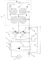
図1は本発明の実施の形態1における誘導加熱調理器の回路構成を示す図である。
図1において,交流電源1に接続される直流電源回路2は、整流回路3とチョークコイル4および平滑コンデンサ5から構成され、交流電源1が印加されたときに交流電力を直流電力に変換する。直流電源回路2の出力側に設けられたインバータ回路6は、直流母線間に直列に接続されたスイッチング素子7、8と、各スイッチング素子7、8にそれぞれ逆並列に接続された逆並列ダイオード9、10とで構成され、各スイッチング素子7、8の動作に基づいて直流電源回路2の出力である直流電力を高周波電力に変換し、例えば4個の加熱コイル12a〜12dと共振コンデンサ13とから構成される共振回路11に高周波電圧を印加する。
FIG. 1 is a diagram showing a circuit configuration of an induction heating cooker according to
In FIG. 1, a DC
前述した加熱コイル12a〜12dは、同等の径・巻数で形成され、本調理器の天板に表示された被加熱体(例えば鍋)の載置位置の下方に格子状に近接して配置されている。これら加熱コイル12a〜12dは、互いに隣接する加熱コイルと導体の巻回方向が逆方向に巻回されており、各内周端がインバータ回路6の出力端であるスイッチング素子7、8の接続点に接続され、外周端は、お互いに接続されて、共通の共振コンデンサ13を介して直流電源出力の低電位側母線に接続され、加熱コイル12a、12cが互いに並列に接続された状態となっている。したがって、加熱コイル12a〜12dには、インバータ回路6の出力電圧と共振コンデンサ13に生ずる共振電圧との差分の同一電圧がそれぞれ印加されることになる。また、各加熱コイル12a〜12dの巻回方向と接続状態とから、加熱コイル12a、12dと加熱コイル12b、12cには、逆巻回方向に高周波電圧が印加されるので、加熱コイル12a、12dと加熱コイル12b、12cには逆方向の高周波電流が流れることになる。
The
入力電流検出回路14は、直流電源回路2の一方の入力側に設置され、本調理器への入力電流を検出する。出力電流検出回路15は、低電位側母線に設置され、共振回路11に流れる出力電流を検出する。ドライブ回路16は、インバータ回路6を構成するスイッチング素子7、8を交互に駆動するパルス信号を出力する。制御部17は、本調理器全体の制御を行うもので、設定火力に応じてドライブ回路16を制御する。
The input
次に、鍋との位置関係による加熱コイルの作用について図2を用いて説明する。図2は実施の形態1における加熱コイルと鍋との位置関係を示す模式図である。なお、(a)(c)は上面から見た加熱コイルと鍋の位置関係を示し、(b)(d)は側面から見た加熱コイルと鍋の位置関係を示している。
(a)・(b)に示すように、天板18上の鍋19が4個の加熱コイル12a〜12dに対して均等に磁気結合する位置に載置された場合は、各加熱コイル12a〜12dのインピーダンスがほぼ同等の値となる。この場合、各加熱コイル12a〜12dには、同じ高周波電圧が印加されるので、各加熱コイル12a〜12dに導体の巻回方向に沿ってほぼ同等の高周波電流が流れる。この高周波電流により生じる高周波磁束は、互いに打ち消し合うことなく重畳し、天板18に載置された鍋19に鎖交する。
Next, the effect | action of the heating coil by the positional relationship with a pan is demonstrated using FIG. FIG. 2 is a schematic diagram showing the positional relationship between the heating coil and the pan in the first embodiment. In addition, (a) and (c) show the positional relationship between the heating coil and the pan as seen from the top surface, and (b) and (d) show the positional relationship between the heating coil and the pan as seen from the side surface.
As shown in (a) and (b), when the
一方、(c)・(d)に示すように、鍋19が加熱コイル12c・12d側の方にずれて載置された場合は、加熱コイル12a・12bは加熱コイル12c・12dと比較して鍋19との磁気結合が弱くなりインダクタンスが大きくなる。その結果、加熱コイル12a・12bに流れる高周波電流は加熱コイル12c・12dに流れる高周波電流と比較して抑制されて小さくなるので、鍋19と鎖交せずに本調理器周辺に漏洩する高周波磁界は抑制される。
On the other hand, as shown in (c) and (d), when the
以上のように実施の形態1によれば、複数の加熱コイル12a〜12dを、互いに隣接する加熱コイルと導体の巻回方向が逆方向になるように配置したので、加熱コイルの隣接側に流れる高周波電流の方向が同一となり、このため、高周波電流による高周波磁束が互いに打ち消し合うことなく重畳し、加熱効率が高く、加熱むらが少ないという効果がある。
As described above, according to the first embodiment, the plurality of
また、4個の加熱コイル12a〜12dに対して共振コンデンサ13を共通にしたので、加熱コイル12a〜12d毎に共振コンデンサを使用する場合と比較べコストの低減や、回路の小型化が容易となり、各加熱コイル12a〜12dに印加する高周波電圧も同一にできるので、各加熱コイル12a〜12dに流れる高周波電流もほぼ同一位相となり、安定した制御が可能となる。
In addition, since the
さらに、加熱コイル12a〜12dの外周端がお互いに接続され、同電位に保たれるので、隣接する加熱コイル12a〜12d間に高電圧がかからなくなり、このため、安全性が高く、加熱コイル12a〜12d間の絶縁性能を高度に保持する必要が無い。
Furthermore, since the outer peripheral ends of the heating coils 12a to 12d are connected to each other and kept at the same potential, a high voltage is not applied between the
なお、前記の実施の形態1では、加熱コイルが4個の場合を示したが、例えば図3に示したように4個以外の加熱コイルを使用してもよく、それらの加熱コイルを並列に接続し、隣接する加熱コイルに互いに逆方向に高周波電圧を印加すればよい。また、図4に示すように、各加熱コイル12a〜12dに対する共振コンデンサをそれぞれ独立して設けるようにしてもよい。この場合も各加熱コイル12a〜12dの外周端を接続して同電位とし、インバータ回路6の出力端側に接続することにより、隣接する加熱コイル12a〜12d間に高電圧が生じるのを回避することができる。
In the first embodiment, four heating coils are shown. However, for example, as shown in FIG. 3, heating coils other than four may be used, and these heating coils are arranged in parallel. What is necessary is just to connect and apply a high frequency voltage to an adjacent heating coil in a mutually reverse direction. Moreover, as shown in FIG. 4, you may make it provide the resonance capacitor with respect to each
実施の形態2.
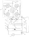
実施の形態2は、格子状に配置された4個の加熱コイル21a〜21dの中央に加熱コイルを加えたものであり、以下、図5および図6を用いて説明する。図5は本発明の実施の形態2における誘導加熱調理器の回路構成を示す図である。なお、図1、2で説明した実施の形態1と同一又は相当部分には同じ符号を付し説明を省略する。
In the second embodiment, a heating coil is added to the center of four
図5おいて,中央加熱コイル20は、加熱コイル21a〜21d(以下、「周辺加熱コイル」という)と同等の径・巻数で形成され、天板の下方に鍋の載置位置の中心軸を中心として配置されている。この中央加熱コイル20は、周辺に近接して配置された周辺加熱コイル21a〜21dの巻回方向と逆方向に巻回されており、その内周端がインバータ回路6の出力端であるスイッチング素子7、8の接続点に接続され、外周端が相互に接続されて、共通の共振コンデンサ13と接続され、中央加熱コイル20と周辺加熱コイル12a〜12dが互いに並列に接続された状態になっている。したがって、中央加熱コイル20と周辺加熱コイル21a〜21dの隣接側に大きな電圧が生じず、また、中央加熱コイル20と周辺加熱コイル21a〜21dには、逆巻回方向の高周波電圧が印加されるので、互いに逆方向の高周波電流が流れる。なお、周辺加熱コイル21a〜21dは、導体の巻回方向が同じであるため、同一方向の高周波電流が流れる。
In FIG. 5, the
次に、鍋との位置関係による加熱コイルの作用について図6を用いて説明する。図6は実施の形態2における加熱コイルと鍋との位置関係を示す側面図である。なお、(a)は大径鍋を載置したときの加熱コイルとの位置関係を示し、(b)は小径鍋を載置したときの加熱コイルとの位置関係を示している。
(a)に示すように、大径鍋19aを天板18に載せた場合、大径鍋19aが中央加熱コイル20と磁気結合するだけでなく、周辺加熱コイル21a〜21dとも磁気結合しており、磁気結合の度合いは中央加熱コイル20の方が周辺加熱コイル21a〜21dよりも多少強い状態である。この場合は、中央加熱コイル20のインダクタンスが周辺加熱コイル21a〜21dのインダクタンスよりも少し小さく、中央加熱コイル20に周辺加熱コイル21a〜21dよりも少し大きい高周波電流が流れる。
Next, the effect | action of the heating coil by the positional relationship with a pan is demonstrated using FIG. FIG. 6 is a side view showing the positional relationship between the heating coil and the pan in the second embodiment. In addition, (a) shows the positional relationship with the heating coil when the large-diameter pan is placed, and (b) shows the positional relationship with the heating coil when the small-diameter pan is placed.
As shown in (a), when the large-
一方、(b)に示すように、小径鍋19bを天板18に載せた場合は、小径鍋19bが中央加熱コイル20とは磁気結合するが、周辺加熱コイル21a〜21d上には、殆ど載っていない状態であるため、殆ど磁気結合していない状態になっている。この場合は、中央加熱コイル20のインダクタンスと比較して周辺加熱コイル21a〜21dのインダクタンスが大幅に大きくなり、周辺加熱コイル21a〜21dに流れる高周波電流は大幅に抑制されて低下する。その結果、周辺加熱コイル21a〜21dに流れる高周波電流により生じる高周波磁束は、小径鍋19bと鎖交せず、本調理器周辺に漏洩する高周波磁束も周辺加熱コイル21a〜21dに流れる高周波電流が抑制される分、少なくなる。
On the other hand, as shown in (b), when the small-
以上のように実施の形態2においては、中央加熱コイル20に流れる高周波電流と周辺加熱コイル21a〜21dに流れる高周波電流が逆方向に流れるので、その隣接側で同一方向に高周波電流が流れ、その高周波電流による磁界がお互いに打ち消しあうことがないので効率よく、加熱むらを抑えて加熱することができる。
As described above, in the second embodiment, the high-frequency current flowing through the
また、鍋と磁気結合した中央加熱コイル20に大きな高周波電流が流れ、磁気結合していない周辺加熱コイル21a〜21dに流れる高周波電流は抑制されるので、本調理器周辺に漏洩する高周波磁束を抑制でき、小径鍋19bに対する加熱効率の低下を抑制することができる。
Moreover, since the high frequency current flows through the
さらに、中央加熱コイル20の外周端と周辺加熱コイル21a〜21dの外周端は相互に接続されて同電位となるので、中央加熱コイル20と周辺加熱コイル21a〜21d間に高電圧は生じず、その分、安全性が高い。
Furthermore, since the outer peripheral end of the
なお、前記の実施の形態2では、中央加熱コイル20は周辺加熱コイル21a〜21dと比較して、鍋と強く磁気結合してインダクタンスが小さくなり、周辺加熱コイル21a〜21dより大きなコイル電流が流れる場合が多いので、中央加熱コイル20の冷却を周辺加熱コイル21a〜21dの冷却より強化することにより、加熱コイル部の温度バランスを改善し、信頼性を高めることができる。
In the second embodiment, the
実施の形態3.
前述した実施の形態2では、中央加熱コイル20と周辺加熱コイル21a〜21dの径・巻数を同一としたが、実施の形態3は、図7に示すように、周辺加熱コイル21a〜21dより中央加熱コイル20aの径を大きく、その巻数を少なくしたものである。中央加熱コイル20aの径を周辺加熱コイル21a〜21dの径より大きくした場合には、中央加熱コイル20aに流れる高周波電流により加熱する鍋底面積は、周辺加熱コイル21a〜21dに流れる高周波電流により加熱する鍋底面積より相対的に広くなるが、中央加熱コイル20aの巻数を減らして中央加熱コイル20aに流れる高周波電流を増やし、中央加熱コイル20aの加熱電力を大きくすることにより、加熱むらの増大を抑制することができる。
In the second embodiment described above, the diameter and the number of turns of the
なお、実施の形態2、3では、図8(a)に示すように、天板18の下方に鍋の載置位置18aの中心軸を中心として中央加熱コイル20aを配置し、その中央加熱コイル20aの周辺に近接して4個の周辺加熱コイル21a〜21dを配置したことを述べたが、図8(b)に示すように、6個の周辺加熱コイル21e〜21jを中央加熱コイル20aの周辺に近接して配置しても良いし、また、同図(c)に示すように、3個の周辺加熱コイル21k〜21mを中央加熱コイル20aの周辺に近接して配置しても良い。
In the second and third embodiments, as shown in FIG. 8A, a
実施の形態4.
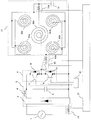
図9は本発明の実施の形態4における誘導加熱調理器の回路構成を示す図である。なお、図7で説明した実施の形態3と同一又は相当部分には同じ符号を付し説明を省略する。
図9において、中央電流検出手段15aは、中央加熱コイル20aと共振コンデンサ13との間に設置され、中央加熱コイル20aに流れる高周波電流を検出する。周辺電流検出手段15bは、インバータ回路6のスイッチング素子7、8の接続点と4個の周辺加熱コイル21a〜21dの接続点との間に設置され、その4個の周辺加熱コイル21a〜21dに流れる高周波電流を検出する。開閉手段22は、インバータ回路6のスイッチング素子7、8の接続点と周辺電流検出手段15bとの間に挿入され、常閉のスイッチである。本実施の形態4の制御部17は、中央電流検出手段15aにより検出された高周波電流に対して、周辺電流検出手段15bによって検出された高周波電流が所定の範囲より低下したときに開閉手段22を開にする周辺加熱コイル切り離し手段を備えている。
FIG. 9 is a diagram showing a circuit configuration of an induction heating cooker according to
In FIG. 9, the central current detection means 15a is installed between the
次に、鍋との位置関係による加熱コイルの作用について図10を用いて説明する。図10は実施の形態4における加熱コイルと鍋との位置関係を示す模式図である。なお、(a)(c)は上面から見た加熱コイルと鍋の位置関係を示し、(b)(d)は側面から見た加熱コイルと鍋の位置関係を示している。
(a)・(b)に示すように、天板18に表示された載置位置18aに大径鍋19aを載せた場合、大径鍋19aが中央加熱コイル20と磁気結合するだけでなく、周辺加熱コイル21a〜21dとも磁気結合し、中央電流検出手段15aにより検出された中央加熱コイル20の高周波電流に対して、周辺電流検出手段15bによって検出された周辺加熱コイル21a〜21dの高周波電流の大きさは所定の範囲の値となる。
Next, the effect | action of the heating coil by the positional relationship with a pan is demonstrated using FIG. FIG. 10 is a schematic diagram showing the positional relationship between the heating coil and the pan in the fourth embodiment. In addition, (a) and (c) show the positional relationship between the heating coil and the pan as seen from the top surface, and (b) and (d) show the positional relationship between the heating coil and the pan as seen from the side surface.
As shown in (a) and (b), when the large-
一方、(c)・(d)に示すように、天板18の載置位置18aに小径鍋19bを載せた場合は、中央加熱コイル20とは磁気結合するが、周辺加熱コイル21a〜21d上には、殆ど載っていない状態であるため、殆ど磁気結合していない状態になっている。この場合は、中央電流検出手段15aにより検出された中央加熱コイル20の高周波電流に対して、周辺電流検出手段15bで検出された周辺加熱コイル21a〜21dの高周波電流の大きさは大幅に抑制され、所定の範囲より低下する。この場合、制御部17の制御によって常閉の開閉手段22が開となり、周辺加熱コイル21a〜21dをインバータ回路6の出力から切り離し、周辺加熱コイル21a〜21dに流れる高周波電流を遮断する。
これにより、本調理器周辺に漏洩する高周波磁束を抑制でき、小径鍋19bに対する加熱効率の低下をより抑制することができる。
On the other hand, as shown in (c) and (d), when the small-
Thereby, the high frequency magnetic flux which leaks to this cooker periphery can be suppressed, and the fall of the heating efficiency with respect to the
1 直流電源回路、6 インバータ回路、11 共振回路、12a〜12d 加熱コイル、13 共振コンデンサ、14 入力電流検出回路、15 出力電流検出回路、
15a 中央電流検出手段、15b 周辺電流検出手段、16 ドライブ回路、17 制御部、18 天板、18a 鍋の載置位置、19 鍋、19a 大径鍋、19b 小径鍋、22 開閉手段。
1 DC power supply circuit, 6 inverter circuit, 11 resonance circuit, 12a to 12d heating coil, 13 resonance capacitor, 14 input current detection circuit, 15 output current detection circuit,
15a central current detection means, 15b peripheral current detection means, 16 drive circuit, 17 control unit, 18 top plate, 18a pan placement position, 19 pan, 19a large diameter pan, 19b small diameter pan, 22 opening / closing means.
Claims (5)
前記天板の下方に載置位置の中心軸近傍に配置され、前記被加熱体を単独で加熱可能な中央加熱コイルと、
前記中央加熱コイルの周辺に近接して配置された複数の周辺加熱コイルと、
前記中央加熱コイルおよび複数の周辺加熱コイルに高周波電圧を印加するインバータ回路と、
前記インバータ回路の出力を制御する制御部とを備え、
前記中央加熱コイルと前記複数の周辺加熱コイルとに、逆周回方向に高周波電圧を印加することを特徴とする誘導加熱調理器。 A top plate displaying the position of the object to be heated;
A central heating coil disposed below the top plate in the vicinity of the central axis of the mounting position and capable of heating the heated object alone;
A plurality of peripheral heating coils disposed proximate to the periphery of the central heating coil;
An inverter circuit for applying a high frequency voltage to the central heating coil and the plurality of peripheral heating coils;
A control unit for controlling the output of the inverter circuit,
An induction heating cooker, wherein a high-frequency voltage is applied to the central heating coil and the plurality of peripheral heating coils in a reverse circulation direction.
前記周辺加熱コイルに流れる高周波電流を検出する周辺電流検出手段とを備え、
前記制御部は、前記中央加熱コイルに流れる高周波電流に対する前記周辺加熱コイルに流れる高周波電流が所定の範囲より低下したときには、前記インバータ回路を制御して前記周辺加熱コイルへの高周波電圧の印加を停止することを特徴とする請求項1記載の誘導加熱調理器。 A central current detecting means for detecting a high-frequency current flowing in the central heating coil;
A peripheral current detection means for detecting a high-frequency current flowing in the peripheral heating coil,
The controller controls the inverter circuit to stop the application of the high frequency voltage to the peripheral heating coil when the high frequency current flowing to the peripheral heating coil with respect to the high frequency current flowing to the central heating coil falls below a predetermined range. The induction heating cooker according to claim 1, wherein:
Priority Applications (1)
| Application Number | Priority Date | Filing Date | Title |
|---|---|---|---|
| JP2010157553A JP5073019B2 (en) | 2010-07-12 | 2010-07-12 | Induction heating cooker |
Applications Claiming Priority (1)
| Application Number | Priority Date | Filing Date | Title |
|---|---|---|---|
| JP2010157553A JP5073019B2 (en) | 2010-07-12 | 2010-07-12 | Induction heating cooker |
Related Parent Applications (1)
| Application Number | Title | Priority Date | Filing Date |
|---|---|---|---|
| JP2008117255A Division JP5137675B2 (en) | 2008-04-28 | 2008-04-28 | Induction heating cooker |
Publications (2)
| Publication Number | Publication Date |
|---|---|
| JP2010232196A true JP2010232196A (en) | 2010-10-14 |
| JP5073019B2 JP5073019B2 (en) | 2012-11-14 |
Family
ID=43047797
Family Applications (1)
| Application Number | Title | Priority Date | Filing Date |
|---|---|---|---|
| JP2010157553A Active JP5073019B2 (en) | 2010-07-12 | 2010-07-12 | Induction heating cooker |
Country Status (1)
| Country | Link |
|---|---|
| JP (1) | JP5073019B2 (en) |
Cited By (4)
| Publication number | Priority date | Publication date | Assignee | Title |
|---|---|---|---|---|
| JP2015228351A (en) * | 2014-06-02 | 2015-12-17 | 日立アプライアンス株式会社 | Induction heating device and induction heating device control method |
| KR20160039955A (en) * | 2014-10-02 | 2016-04-12 | 엘지전자 주식회사 | Induction heat cooking apparatus and method for driving the same |
| JP2020095865A (en) * | 2018-12-13 | 2020-06-18 | 三星電子株式会社Samsung Electronics Co.,Ltd. | Induction heating apparatus |
| US11596029B2 (en) | 2018-12-13 | 2023-02-28 | Samsung Electronics Co., Ltd. | Induction heating apparatus |
Citations (4)
| Publication number | Priority date | Publication date | Assignee | Title |
|---|---|---|---|---|
| JPS63164196U (en) * | 1987-04-15 | 1988-10-26 | ||
| JP2007265877A (en) * | 2006-03-29 | 2007-10-11 | Mitsubishi Electric Corp | Induction heating cooker |
| JP2008047463A (en) * | 2006-08-18 | 2008-02-28 | Mitsubishi Electric Corp | Induction heating cooker |
| WO2010101135A1 (en) * | 2009-03-06 | 2010-09-10 | 三菱電機株式会社 | Induction cooking device |
-
2010
- 2010-07-12 JP JP2010157553A patent/JP5073019B2/en active Active
Patent Citations (4)
| Publication number | Priority date | Publication date | Assignee | Title |
|---|---|---|---|---|
| JPS63164196U (en) * | 1987-04-15 | 1988-10-26 | ||
| JP2007265877A (en) * | 2006-03-29 | 2007-10-11 | Mitsubishi Electric Corp | Induction heating cooker |
| JP2008047463A (en) * | 2006-08-18 | 2008-02-28 | Mitsubishi Electric Corp | Induction heating cooker |
| WO2010101135A1 (en) * | 2009-03-06 | 2010-09-10 | 三菱電機株式会社 | Induction cooking device |
Cited By (6)
| Publication number | Priority date | Publication date | Assignee | Title |
|---|---|---|---|---|
| JP2015228351A (en) * | 2014-06-02 | 2015-12-17 | 日立アプライアンス株式会社 | Induction heating device and induction heating device control method |
| KR20160039955A (en) * | 2014-10-02 | 2016-04-12 | 엘지전자 주식회사 | Induction heat cooking apparatus and method for driving the same |
| KR102182624B1 (en) * | 2014-10-02 | 2020-11-24 | 엘지전자 주식회사 | Induction heat cooking apparatus and method for driving the same |
| JP2020095865A (en) * | 2018-12-13 | 2020-06-18 | 三星電子株式会社Samsung Electronics Co.,Ltd. | Induction heating apparatus |
| EP3858107A4 (en) * | 2018-12-13 | 2021-11-24 | Samsung Electronics Co., Ltd. | Induction heating apparatus |
| US11596029B2 (en) | 2018-12-13 | 2023-02-28 | Samsung Electronics Co., Ltd. | Induction heating apparatus |
Also Published As
| Publication number | Publication date |
|---|---|
| JP5073019B2 (en) | 2012-11-14 |
Similar Documents
| Publication | Publication Date | Title |
|---|---|---|
| JP5658692B2 (en) | Induction heating device | |
| JP4804450B2 (en) | Induction heating cooker | |
| JP4864850B2 (en) | Induction heating cooker | |
| JP4845432B2 (en) | Induction heating cooker | |
| JP5599479B2 (en) | Induction heating cooker | |
| JP5844017B1 (en) | Induction heating cooker and control method thereof | |
| JP4863862B2 (en) | Induction heating cooker | |
| JPWO2012114405A1 (en) | Induction heating cooker | |
| JP4969676B2 (en) | Induction heating cooker | |
| JP5137675B2 (en) | Induction heating cooker | |
| JP4781295B2 (en) | Induction heating cooker | |
| JP5073019B2 (en) | Induction heating cooker | |
| JP2008053056A (en) | Induction heating cooker | |
| JP2010219071A (en) | Induction heating cooker | |
| JP4450813B2 (en) | Induction heating cooker | |
| JP5807161B2 (en) | Induction heating apparatus and rice cooker using the same | |
| JP2016207544A (en) | Induction heating cooker | |
| JP5734390B2 (en) | Induction heating cooker | |
| JP5674896B2 (en) | Induction heating cooker | |
| JP5836743B2 (en) | Induction heating cooker | |
| JP5025563B2 (en) | Induction heating cooker | |
| JP5174222B2 (en) | Induction heating cooker | |
| JP5289537B2 (en) | Induction heating cooker | |
| JP5404743B2 (en) | Induction heating cooker | |
| JP7222806B2 (en) | Electromagnetic induction heating device |
Legal Events
| Date | Code | Title | Description |
|---|---|---|---|
| A621 | Written request for application examination |
Free format text: JAPANESE INTERMEDIATE CODE: A621 Effective date: 20100712 |
|
| A131 | Notification of reasons for refusal |
Free format text: JAPANESE INTERMEDIATE CODE: A131 Effective date: 20120327 |
|
| A521 | Request for written amendment filed |
Free format text: JAPANESE INTERMEDIATE CODE: A523 Effective date: 20120522 |
|
| TRDD | Decision of grant or rejection written | ||
| A01 | Written decision to grant a patent or to grant a registration (utility model) |
Free format text: JAPANESE INTERMEDIATE CODE: A01 Effective date: 20120724 |
|
| A01 | Written decision to grant a patent or to grant a registration (utility model) |
Free format text: JAPANESE INTERMEDIATE CODE: A01 |
|
| A61 | First payment of annual fees (during grant procedure) |
Free format text: JAPANESE INTERMEDIATE CODE: A61 Effective date: 20120821 |
|
| R150 | Certificate of patent or registration of utility model |
Ref document number: 5073019 Country of ref document: JP Free format text: JAPANESE INTERMEDIATE CODE: R150 |
|
| FPAY | Renewal fee payment (event date is renewal date of database) |
Free format text: PAYMENT UNTIL: 20150831 Year of fee payment: 3 |
|
| R250 | Receipt of annual fees |
Free format text: JAPANESE INTERMEDIATE CODE: R250 |
|
| R250 | Receipt of annual fees |
Free format text: JAPANESE INTERMEDIATE CODE: R250 |
|
| R250 | Receipt of annual fees |
Free format text: JAPANESE INTERMEDIATE CODE: R250 |
|
| R250 | Receipt of annual fees |
Free format text: JAPANESE INTERMEDIATE CODE: R250 |
|
| R250 | Receipt of annual fees |
Free format text: JAPANESE INTERMEDIATE CODE: R250 |
|
| R250 | Receipt of annual fees |
Free format text: JAPANESE INTERMEDIATE CODE: R250 |
|
| R250 | Receipt of annual fees |
Free format text: JAPANESE INTERMEDIATE CODE: R250 |
|
| R250 | Receipt of annual fees |
Free format text: JAPANESE INTERMEDIATE CODE: R250 |
|
| R250 | Receipt of annual fees |
Free format text: JAPANESE INTERMEDIATE CODE: R250 |