JP2010081756A - Battery information acquiring device - Google Patents
Battery information acquiring device Download PDFInfo
- Publication number
- JP2010081756A JP2010081756A JP2008248691A JP2008248691A JP2010081756A JP 2010081756 A JP2010081756 A JP 2010081756A JP 2008248691 A JP2008248691 A JP 2008248691A JP 2008248691 A JP2008248691 A JP 2008248691A JP 2010081756 A JP2010081756 A JP 2010081756A
- Authority
- JP
- Japan
- Prior art keywords
- voltage
- battery information
- circuit
- battery
- information acquisition
- Prior art date
- Legal status (The legal status is an assumption and is not a legal conclusion. Google has not performed a legal analysis and makes no representation as to the accuracy of the status listed.)
- Granted
Links
Images


Classifications
-
- H—ELECTRICITY
- H01—ELECTRIC ELEMENTS
- H01M—PROCESSES OR MEANS, e.g. BATTERIES, FOR THE DIRECT CONVERSION OF CHEMICAL ENERGY INTO ELECTRICAL ENERGY
- H01M10/00—Secondary cells; Manufacture thereof
- H01M10/42—Methods or arrangements for servicing or maintenance of secondary cells or secondary half-cells
- H01M10/48—Accumulators combined with arrangements for measuring, testing or indicating the condition of cells, e.g. the level or density of the electrolyte
- H01M10/486—Accumulators combined with arrangements for measuring, testing or indicating the condition of cells, e.g. the level or density of the electrolyte for measuring temperature
-
- B—PERFORMING OPERATIONS; TRANSPORTING
- B60—VEHICLES IN GENERAL
- B60L—PROPULSION OF ELECTRICALLY-PROPELLED VEHICLES; SUPPLYING ELECTRIC POWER FOR AUXILIARY EQUIPMENT OF ELECTRICALLY-PROPELLED VEHICLES; ELECTRODYNAMIC BRAKE SYSTEMS FOR VEHICLES IN GENERAL; MAGNETIC SUSPENSION OR LEVITATION FOR VEHICLES; MONITORING OPERATING VARIABLES OF ELECTRICALLY-PROPELLED VEHICLES; ELECTRIC SAFETY DEVICES FOR ELECTRICALLY-PROPELLED VEHICLES
- B60L3/00—Electric devices on electrically-propelled vehicles for safety purposes; Monitoring operating variables, e.g. speed, deceleration or energy consumption
- B60L3/0023—Detecting, eliminating, remedying or compensating for drive train abnormalities, e.g. failures within the drive train
- B60L3/0046—Detecting, eliminating, remedying or compensating for drive train abnormalities, e.g. failures within the drive train relating to electric energy storage systems, e.g. batteries or capacitors
-
- B—PERFORMING OPERATIONS; TRANSPORTING
- B60—VEHICLES IN GENERAL
- B60L—PROPULSION OF ELECTRICALLY-PROPELLED VEHICLES; SUPPLYING ELECTRIC POWER FOR AUXILIARY EQUIPMENT OF ELECTRICALLY-PROPELLED VEHICLES; ELECTRODYNAMIC BRAKE SYSTEMS FOR VEHICLES IN GENERAL; MAGNETIC SUSPENSION OR LEVITATION FOR VEHICLES; MONITORING OPERATING VARIABLES OF ELECTRICALLY-PROPELLED VEHICLES; ELECTRIC SAFETY DEVICES FOR ELECTRICALLY-PROPELLED VEHICLES
- B60L58/00—Methods or circuit arrangements for monitoring or controlling batteries or fuel cells, specially adapted for electric vehicles
- B60L58/10—Methods or circuit arrangements for monitoring or controlling batteries or fuel cells, specially adapted for electric vehicles for monitoring or controlling batteries
- B60L58/18—Methods or circuit arrangements for monitoring or controlling batteries or fuel cells, specially adapted for electric vehicles for monitoring or controlling batteries of two or more battery modules
- B60L58/21—Methods or circuit arrangements for monitoring or controlling batteries or fuel cells, specially adapted for electric vehicles for monitoring or controlling batteries of two or more battery modules having the same nominal voltage
-
- G—PHYSICS
- G01—MEASURING; TESTING
- G01R—MEASURING ELECTRIC VARIABLES; MEASURING MAGNETIC VARIABLES
- G01R31/00—Arrangements for testing electric properties; Arrangements for locating electric faults; Arrangements for electrical testing characterised by what is being tested not provided for elsewhere
- G01R31/36—Arrangements for testing, measuring or monitoring the electrical condition of accumulators or electric batteries, e.g. capacity or state of charge [SoC]
- G01R31/396—Acquisition or processing of data for testing or for monitoring individual cells or groups of cells within a battery
-
- H—ELECTRICITY
- H01—ELECTRIC ELEMENTS
- H01M—PROCESSES OR MEANS, e.g. BATTERIES, FOR THE DIRECT CONVERSION OF CHEMICAL ENERGY INTO ELECTRICAL ENERGY
- H01M10/00—Secondary cells; Manufacture thereof
- H01M10/42—Methods or arrangements for servicing or maintenance of secondary cells or secondary half-cells
- H01M10/425—Structural combination with electronic components, e.g. electronic circuits integrated to the outside of the casing
-
- H—ELECTRICITY
- H01—ELECTRIC ELEMENTS
- H01M—PROCESSES OR MEANS, e.g. BATTERIES, FOR THE DIRECT CONVERSION OF CHEMICAL ENERGY INTO ELECTRICAL ENERGY
- H01M10/00—Secondary cells; Manufacture thereof
- H01M10/42—Methods or arrangements for servicing or maintenance of secondary cells or secondary half-cells
- H01M10/48—Accumulators combined with arrangements for measuring, testing or indicating the condition of cells, e.g. the level or density of the electrolyte
- H01M10/482—Accumulators combined with arrangements for measuring, testing or indicating the condition of cells, e.g. the level or density of the electrolyte for several batteries or cells simultaneously or sequentially
-
- B—PERFORMING OPERATIONS; TRANSPORTING
- B60—VEHICLES IN GENERAL
- B60L—PROPULSION OF ELECTRICALLY-PROPELLED VEHICLES; SUPPLYING ELECTRIC POWER FOR AUXILIARY EQUIPMENT OF ELECTRICALLY-PROPELLED VEHICLES; ELECTRODYNAMIC BRAKE SYSTEMS FOR VEHICLES IN GENERAL; MAGNETIC SUSPENSION OR LEVITATION FOR VEHICLES; MONITORING OPERATING VARIABLES OF ELECTRICALLY-PROPELLED VEHICLES; ELECTRIC SAFETY DEVICES FOR ELECTRICALLY-PROPELLED VEHICLES
- B60L2240/00—Control parameters of input or output; Target parameters
- B60L2240/40—Drive Train control parameters
- B60L2240/54—Drive Train control parameters related to batteries
- B60L2240/545—Temperature
-
- B—PERFORMING OPERATIONS; TRANSPORTING
- B60—VEHICLES IN GENERAL
- B60L—PROPULSION OF ELECTRICALLY-PROPELLED VEHICLES; SUPPLYING ELECTRIC POWER FOR AUXILIARY EQUIPMENT OF ELECTRICALLY-PROPELLED VEHICLES; ELECTRODYNAMIC BRAKE SYSTEMS FOR VEHICLES IN GENERAL; MAGNETIC SUSPENSION OR LEVITATION FOR VEHICLES; MONITORING OPERATING VARIABLES OF ELECTRICALLY-PROPELLED VEHICLES; ELECTRIC SAFETY DEVICES FOR ELECTRICALLY-PROPELLED VEHICLES
- B60L2240/00—Control parameters of input or output; Target parameters
- B60L2240/40—Drive Train control parameters
- B60L2240/54—Drive Train control parameters related to batteries
- B60L2240/547—Voltage
-
- B—PERFORMING OPERATIONS; TRANSPORTING
- B60—VEHICLES IN GENERAL
- B60L—PROPULSION OF ELECTRICALLY-PROPELLED VEHICLES; SUPPLYING ELECTRIC POWER FOR AUXILIARY EQUIPMENT OF ELECTRICALLY-PROPELLED VEHICLES; ELECTRODYNAMIC BRAKE SYSTEMS FOR VEHICLES IN GENERAL; MAGNETIC SUSPENSION OR LEVITATION FOR VEHICLES; MONITORING OPERATING VARIABLES OF ELECTRICALLY-PROPELLED VEHICLES; ELECTRIC SAFETY DEVICES FOR ELECTRICALLY-PROPELLED VEHICLES
- B60L2240/00—Control parameters of input or output; Target parameters
- B60L2240/40—Drive Train control parameters
- B60L2240/54—Drive Train control parameters related to batteries
- B60L2240/549—Current
-
- G—PHYSICS
- G01—MEASURING; TESTING
- G01R—MEASURING ELECTRIC VARIABLES; MEASURING MAGNETIC VARIABLES
- G01R31/00—Arrangements for testing electric properties; Arrangements for locating electric faults; Arrangements for electrical testing characterised by what is being tested not provided for elsewhere
- G01R31/36—Arrangements for testing, measuring or monitoring the electrical condition of accumulators or electric batteries, e.g. capacity or state of charge [SoC]
- G01R31/382—Arrangements for monitoring battery or accumulator variables, e.g. SoC
- G01R31/3835—Arrangements for monitoring battery or accumulator variables, e.g. SoC involving only voltage measurements
-
- Y—GENERAL TAGGING OF NEW TECHNOLOGICAL DEVELOPMENTS; GENERAL TAGGING OF CROSS-SECTIONAL TECHNOLOGIES SPANNING OVER SEVERAL SECTIONS OF THE IPC; TECHNICAL SUBJECTS COVERED BY FORMER USPC CROSS-REFERENCE ART COLLECTIONS [XRACs] AND DIGESTS
- Y02—TECHNOLOGIES OR APPLICATIONS FOR MITIGATION OR ADAPTATION AGAINST CLIMATE CHANGE
- Y02E—REDUCTION OF GREENHOUSE GAS [GHG] EMISSIONS, RELATED TO ENERGY GENERATION, TRANSMISSION OR DISTRIBUTION
- Y02E60/00—Enabling technologies; Technologies with a potential or indirect contribution to GHG emissions mitigation
- Y02E60/10—Energy storage using batteries
-
- Y—GENERAL TAGGING OF NEW TECHNOLOGICAL DEVELOPMENTS; GENERAL TAGGING OF CROSS-SECTIONAL TECHNOLOGIES SPANNING OVER SEVERAL SECTIONS OF THE IPC; TECHNICAL SUBJECTS COVERED BY FORMER USPC CROSS-REFERENCE ART COLLECTIONS [XRACs] AND DIGESTS
- Y02—TECHNOLOGIES OR APPLICATIONS FOR MITIGATION OR ADAPTATION AGAINST CLIMATE CHANGE
- Y02T—CLIMATE CHANGE MITIGATION TECHNOLOGIES RELATED TO TRANSPORTATION
- Y02T10/00—Road transport of goods or passengers
- Y02T10/60—Other road transportation technologies with climate change mitigation effect
- Y02T10/70—Energy storage systems for electromobility, e.g. batteries
-
- Y—GENERAL TAGGING OF NEW TECHNOLOGICAL DEVELOPMENTS; GENERAL TAGGING OF CROSS-SECTIONAL TECHNOLOGIES SPANNING OVER SEVERAL SECTIONS OF THE IPC; TECHNICAL SUBJECTS COVERED BY FORMER USPC CROSS-REFERENCE ART COLLECTIONS [XRACs] AND DIGESTS
- Y02—TECHNOLOGIES OR APPLICATIONS FOR MITIGATION OR ADAPTATION AGAINST CLIMATE CHANGE
- Y02T—CLIMATE CHANGE MITIGATION TECHNOLOGIES RELATED TO TRANSPORTATION
- Y02T90/00—Enabling technologies or technologies with a potential or indirect contribution to GHG emissions mitigation
- Y02T90/10—Technologies relating to charging of electric vehicles
- Y02T90/16—Information or communication technologies improving the operation of electric vehicles
Landscapes
- Engineering & Computer Science (AREA)
- Manufacturing & Machinery (AREA)
- Chemical & Material Sciences (AREA)
- Chemical Kinetics & Catalysis (AREA)
- Electrochemistry (AREA)
- General Chemical & Material Sciences (AREA)
- Power Engineering (AREA)
- Sustainable Development (AREA)
- Life Sciences & Earth Sciences (AREA)
- Sustainable Energy (AREA)
- Transportation (AREA)
- Mechanical Engineering (AREA)
- Microelectronics & Electronic Packaging (AREA)
- Physics & Mathematics (AREA)
- General Physics & Mathematics (AREA)
- Charge And Discharge Circuits For Batteries Or The Like (AREA)
- Secondary Cells (AREA)
- Tests Of Electric Status Of Batteries (AREA)
Abstract
Description
この発明は、複数の電池セルを直列に接続した組電池における当該電池セルから電池情報を取得して、組電池を管理する管理ユニットに送信する電池情報取得装置に関する。 The present invention relates to a battery information acquisition device that acquires battery information from a battery cell in an assembled battery in which a plurality of battery cells are connected in series, and transmits the battery information to a management unit that manages the assembled battery.
電気自動車や産業用車両に用いられる電池電源として、高電圧・大容量の電圧を得るために低電圧・低容量の電池セルを多直並列に接続した組電池が用いられている。組電池を安全に動作させるために、各電池セルの電圧や温度など、電池セルの電池情報をモニタする電池情報管理システムが必要である。 As a battery power source used for electric vehicles and industrial vehicles, an assembled battery in which low-voltage and low-capacity battery cells are connected in series and parallel to obtain a high-voltage and large-capacity voltage is used. In order to operate the assembled battery safely, a battery information management system that monitors battery information of the battery cells such as the voltage and temperature of each battery cell is required.
従来の電池情報管理システムは、電池セル、電池情報取得回路、送受信回路(通信回路)を含む複数の電池情報取得モジュールを有し、各電池情報取得モジュールと管理ユニット間で通信および制御を行っている。 A conventional battery information management system has a plurality of battery information acquisition modules including a battery cell, a battery information acquisition circuit, and a transmission / reception circuit (communication circuit), and performs communication and control between each battery information acquisition module and the management unit. Yes.
各電池情報取得モジュールはそれぞれの電池セルから電源およびGNDが常時供給されており、したがって管理ユニットとの間で制御信号や電池情報の通信を行わない待機時にも、電力を消費してしまう問題がある。 Each battery information acquisition module is constantly supplied with power and GND from each battery cell. Therefore, there is a problem that power is consumed even during standby in which control signals and battery information are not communicated with the management unit. is there.
また各電池情報取得モジュールは各電池セルから取得した電池情報をそれぞれ管理ユニットに対し差動信号により送信するが、この際、各電池情報取得モジュールから送信する差動信号はそれぞれ同相電圧が異なる。このため、各電池情報取得モジュールから2本ずつの配線を管理ユニットにそれぞれ別個に接続し、それぞれの配線を介して送信を行う必要がある。これにより配線の引き回しが煩雑になる問題があった。 Each battery information acquisition module transmits battery information acquired from each battery cell to the management unit as a differential signal. At this time, the differential signal transmitted from each battery information acquisition module has a different common-mode voltage. For this reason, it is necessary to connect two wires from each battery information acquisition module to the management unit separately and perform transmission via each wire. As a result, there is a problem that wiring is complicated.
また、管理ユニット側にも、各電池情報取得モジュールのそれぞれに対応して異なる同相電圧の信号をレベルシフトする機能を持たせなければならなかったり、耐圧を確保しなければいけなかったりするなどの問題があった。
本発明は、消費電力をできるだけ低く抑えて電池セルから電池情報を取得して管理ユニットに送信する電池情報取得装置を簡易な構成により提供しようとするものである。 The present invention intends to provide a battery information acquisition device that acquires battery information from a battery cell and transmits it to a management unit while keeping power consumption as low as possible with a simple configuration.
本発明の一態様としての電池情報取得装置は、
複数の電池セルを直列に接続した組電池における前記電池セルの電池情報を取得し、取得した電池情報を、前記組電池の状態を管理する管理ユニットに、前記複数の電池セルのうち他の電池セルの電池情報を取得する他の電池情報取得装置と共通に接続された共通配線を介して送信する、電池情報取得装置であって、
前記電池セルの端子間電圧を取得する電圧取得手段と、
前記電圧取得手段による取得電圧が電源電圧として供給され、前記電池セルから電池情報を取得する電池情報取得回路と、
前記共通配線に接続された1次側巻線と、2次側巻線と、を有するトランスと、
前記トランスの2次側巻線に接続され、前記取得電圧が電源電圧として供給され、前記電池情報の信号を前記トランスを介して前記管理ユニットに送信する通信回路と、
前記トランスの2次側巻線に接続され、前記管理ユニットから送信される所定周波数の信号を前記トランスを介して受信し、受信した前記信号を整流して直流電圧を生成する整流回路と、
前記トランスの2次側巻線に接続され、前記整流回路により生成された直流電圧が電源電圧として供給され、前記電池情報取得回路および前記通信回路に対する前記電源電圧の供給を制御する制御回路と、を備え、
前記制御回路は、
前記電池情報取得回路に対する前記電源電圧の供給の有無を指示する第1指示信号を前記管理ユニットから前記トランスを介して受信する第1の受信手段と、
前記通信回路に対する前記電源電圧の供給の有無を指示する第2指示信号を前記管理ユニットから前記トランスを介して受信する第2の受信手段と、
前記第1指示信号に応じて前記電池情報取得回路に対する前記電源電圧の供給の有無を切り替え制御する第1の切替制御手段と、
前記第2指示信号に応じて前記通信回路に対する前記電源電圧の供給の有無を切り替え制御する第2の切替制御手段と、
を備えたことを特徴とする。
The battery information acquisition device as one aspect of the present invention is:
The battery information of the battery cell in an assembled battery in which a plurality of battery cells are connected in series is acquired, and the acquired battery information is sent to a management unit that manages the state of the assembled battery. A battery information acquisition device that transmits via a common wiring connected in common with other battery information acquisition devices for acquiring battery information of a cell,
Voltage acquisition means for acquiring a voltage between terminals of the battery cell;
A battery information acquisition circuit for acquiring battery information from the battery cell, wherein the acquisition voltage by the voltage acquisition means is supplied as a power supply voltage;
A transformer having a primary winding connected to the common wiring and a secondary winding;
A communication circuit connected to the secondary winding of the transformer, the acquired voltage being supplied as a power supply voltage, and transmitting the battery information signal to the management unit via the transformer;
A rectifier circuit connected to the secondary winding of the transformer, receiving a signal of a predetermined frequency transmitted from the management unit via the transformer, and rectifying the received signal to generate a DC voltage;
A control circuit connected to the secondary winding of the transformer, supplied with a DC voltage generated by the rectifier circuit as a power supply voltage, and controlling the supply of the power supply voltage to the battery information acquisition circuit and the communication circuit; With
The control circuit includes:
First receiving means for receiving from the management unit via the transformer a first instruction signal instructing whether or not to supply the power supply voltage to the battery information acquisition circuit;
Second receiving means for receiving a second instruction signal for instructing whether or not the power supply voltage is supplied to the communication circuit from the management unit via the transformer;
First switching control means for switching the presence or absence of supply of the power supply voltage to the battery information acquisition circuit according to the first instruction signal;
Second switching control means for switching the presence or absence of supply of the power supply voltage to the communication circuit in response to the second instruction signal;
It is provided with.
本発明により、消費電力をできるだけ低く抑えつつ簡易な構成により電池セルから電池情報を取得して管理ユニットに送信することが可能になる。 According to the present invention, it is possible to acquire battery information from the battery cell and transmit it to the management unit with a simple configuration while keeping power consumption as low as possible.
以下、図面を参照しながら本実施の形態について詳細に説明する。 Hereinafter, the present embodiment will be described in detail with reference to the drawings.
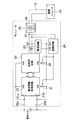
図1は、本発明の実施の形態に係わる電池情報管理システムの構成を概略的に示すブロック図である。この電池情報管理システムは、たとえば車両システムまたは電動自転車など、組電池を用いて動作する車両等のシステムまたは装置に対して組み込むことができる。 FIG. 1 is a block diagram schematically showing a configuration of a battery information management system according to an embodiment of the present invention. This battery information management system can be incorporated into a system or device such as a vehicle that operates using an assembled battery, such as a vehicle system or an electric bicycle.
図1の電池情報管理システムは、複数の電池セルを直列に接続した組電池11と、組電池の状態を管理する管理ユニット12と、組電池11における電池セルから電池情報を取得して管理ユニットに送信する複数の電池情報取得モジュール(電池情報取得装置)13とを備える。各電池情報取得モジュール13はそれぞれ異なる電池セルに接続されている。
The battery information management system in FIG. 1 includes an assembled battery 11 in which a plurality of battery cells are connected in series, a
組電池11は、直列接続された複数の電池セルからなる。このように複数の電池セルを直列に接続することによって、1つの電池セルの電圧よりも高い電圧を得ることができる。さらに大きな電池容量を得るためには、この組電池11を複数用意し、並列に接続すればよい。 The assembled battery 11 includes a plurality of battery cells connected in series. Thus, a voltage higher than the voltage of one battery cell can be obtained by connecting a plurality of battery cells in series. In order to obtain a larger battery capacity, a plurality of the assembled batteries 11 may be prepared and connected in parallel.
各電池情報取得モジュール13は、組電池11における電池セルの両端子(プラス端子およびマイナス端子)間の電圧、または電池セルの温度、などの電池情報を検出し、検出した電池情報を、各電池情報取得モジュール13に共通に接続された共通配線15を介して管理ユニット12に送信する。より詳細には、電池情報取得回路21で電池情報を取得し、送受信回路(通信回路)22により当該電池情報をトランス25を介して管理ユニット12に送信する。
Each battery
各トランス25の1次側巻線36はそれぞれ上記共通配線に接続され、2次側巻線37は送受信回路(通信回路)22等に接続されている。図1では電池情報取得モジュール13の構成要素として電池情報取得回路21、送受信回路22およびトランス25のみが図示されるが、実際には後述する図2に示すように、他の要素も含まれる。
The
各電池取得電池情報取得モジュール13にトランス25を設けることで、管理ユニット12に対し各電池取得電池情報取得モジュール13を共通配線に並列に接続でき、これにより配線の複雑さを防ぐことができる。すなわち電池取得電池情報取得モジュール13ごとに配線を用意する必要はなく、各電池取得電池情報取得モジュール13に共通の配線を用意しさえすればよい。またこのように共通の配線を介して通信を行うことで、管理ユニット12で扱う通信信号の電圧は小さくなり、よって管理ユニット12側で耐圧の高い部品を用意する必要がなくなる。
By providing the
管理ユニット12は、各電池セルのそれぞれに対応する電池情報取得モジュール13から電池情報を共通配線15を介して取得し、組電池が安全に動作するよう、取得した電池情報に基づき、組電池を管理する。管理ユニット12は、取得した電池情報を外部へ出力する機能を有する。
The
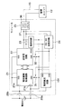
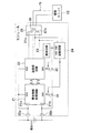
図2は、電池情報取得モジュール13の詳細構成例を示す。
FIG. 2 shows a detailed configuration example of the battery
電池情報取得モジュール13は、電圧取得手段20a、20bと、電池情報取得回路21と、送受信回路(通信回路)22と、整流回路23と、起動回路24と、トランス25とを備える。
The battery
トランス25は、1次側巻線36と2次側巻線37とを有する。1次側巻線は共通配線15を介して管理ユニット12と接続されている。
The
電圧取得手段20a、20bは、それぞれ配線を介して電池セルのプラス端子およびマイナス端子に接続される。これにより電圧取得手段は電池セルの端子間電圧を取得する。取得された電圧は、電池情報取得回路21および送受信回路22の電源電圧(動作電圧)として用いられる。また取得された電圧は、電池情報取得回路21により入力端子21a、21bを介して電池情報として取得される。
The voltage acquisition means 20a and 20b are respectively connected to the positive terminal and the negative terminal of the battery cell via wiring. Thereby, a voltage acquisition means acquires the voltage between terminals of a battery cell. The acquired voltage is used as a power supply voltage (operating voltage) for the battery
電池情報取得回路21はVDD端子とGND端子とを有し、VDD端子は電圧取得手段20aを介して電池セルのプラス端子に、GND端子はスイッチ手段31および電圧取得手段20bを介して電池セルのマイナス端子に接続される。電池情報取得回路21はスイッチ手段31がオンのとき、VDD端子およびGND端子間に電池セルの電圧が電源電圧として与えられ、この電源電圧により動作する(電池情報取得回路21が電源オンとなる)。また電池情報取得回路21は、電圧取得手段20aを介して電池セルのプラス端子に接続される入力端子(電圧入力手段)21aと、電圧取得手段20bを介して電池セルのマイナス端子に接続される入力端子(電圧入力手段)21bを有し、電池情報取得回路21は、入力端子21a、21b間に入力される電圧を、電池情報として取得する。また電池情報取得回路21は、後述する温度センサ(図6参照)を用いて電池セルの温度を電池情報として取得する。電池情報の取得は、送受信回路22から送信指示が入力されたときに行い、電池情報取得回路21は、取得した電池情報を送受信回路22に出力する。
The battery
送受信回路22は、VDD端子とGND端子とを有し、VDD端子は電圧取得手段20aを介して電池セルのプラス端子に、GND端子はスイッチ手段32および電圧取得手段20bを介して電池セルのマイナス端子に接続される。また送受信回路22はトランス25の2次側巻線37に接続されている。送受信回路22は、スイッチ手段32がオンのとき、VDD端子およびGND端子間に電池セルの電圧が電源電圧として与えられ、この電源電圧により動作する(送受信回路22が電源オンとなる)。オン状態のとき、送受信回路22は、トランス25を介して管理ユニット12から交流により送られる送信指示信号を検出し、検出した送信指示を、電池情報取得回路21に出力する。送受信回路22は、送信指示に応答して電池情報取得回路21から入力される電池情報を取得し、取得した電池情報の信号を変調して、トランス25を介して管理ユニット12に送信する。ここで送受信回路22には固有のID(識別子)が付与され、これにより他の電池セルに接続される電池情報取得モジュールの送受信回路と個別に認識可能になっている。電池情報の送信の際は、IDも併せて送信し、これにより、管理ユニット12は受け取った電池情報がどの電池セルからのかを認識できる。管理ユニット12は、取得した電池情報に基づいて、各電池セルの状態を監視し、各電池セルの状態を外部に出力することができる。
The transmission /
整流回路23はトランス25の2次側巻線37に接続され、管理ユニット12から送信される交流信号を、トランス25を介して受信し、受信した交流信号を整流して直流電圧を生成する。整流回路23はGND端子およびVDD端子を有し、生成した直流電圧をこれらの端子を介して起動回路24に与える。
The
起動回路24は、GND端子およびVDD端子を有し、これらの端子を介して整流回路23から直流電圧が電源電圧として与えられる。起動回路24は、直流電圧が与えられると起動状態になる。起動回路24はトランス25の2次側巻線37に接続される。起動状態にある起動回路24は、管理ユニット12から交流により送られる起動信号をトランス25を介して受信すると、スイッチ手段31、32をオンにする電力制御信号を各スイッチ手段31、32に与えることにより各スイッチ手段31、32をオンにする。すなわち、電池情報取得回路21と送受信回路22を電源オン状態にする。また起動回路24は、管理ユニット12から交流により送られる終了信号をトランス25を介して受信すると、スイッチ手段31、32をオフにする電力制御信号を各スイッチ手段31、32に与えることにより各スイッチ手段31、32をオフにする。すなわち、電池情報取得回路21と送受信回路22を電源オフ状態にする。
The
ここではスイッチ手段31、32を同時にオンおよびオフにする例を示したが、それぞれ個別にオンおよびオフを制御するようにしてもよい。すなわち管理ユニット12から第1起動信号(第1指示信号)が受信された場合はスイッチ手段31をオン、第2起動信号(第2指示信号)が受信された場合はスイッチ手段32をオンにし、また、第1終了信号(第1指示信号)が受信された場合はスイッチ手段31をオフ、第2終了信号(第2指示信号)が受信された場合はスイッチ手段32をオフするようにしてもよい。
Here, an example in which the
起動回路24は、第1指示信号を受信する第1の指示信号受信手段、第2指示信号を受信する第2の指示信号受信手段と、第1指示信号の内容に応じてスイッチ手段31のオン・オフ(すなわち電池情報取得回路への電源電圧の供給の有無)を制御する第1の切替制御手段、第2指示信号の内容に応じてスイッチ手段32のオン・オフ(すなわち送受信回路への電源電圧の供給の有無)を制御する第2の切替制御手段を含む。
The
なお、トランス25を介して受信される交流信号は、上述のように送信指示信号または起動信号が含まれている場合、あるいは両方とも含まれていない場合があるが、いずれにしても受信される交流信号は、送受信回路22,整流回路23および起動回路24すべてに入力される。送受信回路22は交流信号から送信指示信号を検出し、起動回路24は起動信号を検出する。整流回路23は、含まれる信号の種類に拘わらず、受信された交流信号を整流して直流電圧を生成する。
Note that the AC signal received via the
以上の構成において、次にその動作の一例について説明する。 Next, an example of the operation of the above configuration will be described.
最初、スイッチ31、32はそれぞれオフにされており、したがって電池情報取得回路21および送受信回路22の電源はオフである。この状態において電池情報を取得し送信する手順を以下に示す。
Initially, the
まず管理ユニット12から所定周波数の交流信号が送信され、送信された交流信号はトランス25を介して整流回路23に入力され、直流電圧に変換される。この直流電圧は起動回路24にその電源電圧として与えられる。これにより起動回路24が動作可能になる。
First, an AC signal having a predetermined frequency is transmitted from the
次に管理ユニット12から交流信号に含められて起動信号が送信されトランス25を介して起動回路24に受信される。起動回路24はこの起動信号を検出する。起動信号を検出したら起動回路24はスイッチ31,32をオンにする電源制御信号を生成し、スイッチ31、32に送る。これによりスイッチ31、32はオンになり、電池情報取得回路21と送受信回路22は電源オンになる。
Next, the activation signal is included in the AC signal from the
次に、管理ユニット12から交流信号に含められて送信指示信号が送信され、トランス25を介して送受信回路22において受信される。送受信回路22はこの送信指示信号を検出し、この送信指示信号を、電池情報取得回路21を動作させる命令(送信指示)に変換し、電池情報取得回路21に送る。
Next, a transmission instruction signal is transmitted from the
電池情報取得回路21はこの送信指示を受けたら、電池情報を取得し、取得した電池情報を送受信回路22に渡す。送受信回路22は、受けた電池情報を変調して、管理ユニット12にトランス25を介して送信する。
Upon receiving this transmission instruction, the battery
電池情報を取得した管理ユニット12は、終了信号を交流信号に含めて送信する。この終了信号はトランス25を介して起動回路24により受信され検出される。起動回路24は終了信号を検出したら、スイッチ31、32をオフにする電力制御信号を生成し、スイッチ31、32に送る。これによりスイッチ31、32はオフになり、電池情報取得回路21と送受信回路22は電源オフになる。
The
なお、上記の動作の間、整流回路23には管理ユニット12からの交流信号が常時入力され、整流動作を行っているものとする。
Note that during the above operation, it is assumed that the AC signal from the
以上のように、トランス25を介して受信した交流信号を整流して直流電圧を生成し、生成した直流電圧を用いて、電池情報取得回路21や送受信回路22の電源をオン/オフ制御する起動回路(制御回路)を駆動することにより、電池情報取得回路21や送受信回路22が動作しない待機時に、電池セルから消費する電力を低減することが可能となる。
As described above, the AC signal received via the
図2に示した構成では、電池情報取得回路21および送受信回路22は電池セルの電圧を直接、電源電圧として用いていたが、電池セルの電圧をDC−DC変換し、DC−DC変換された電圧(電池セルの電圧より低いまたは高い電圧)を、電源電圧として用いてもよい。これには図3に示すように電池セルの電圧をDC−DC変換する電源回路41を設け、電池セルの電圧を電源回路41にて一旦DC−DC変換し、変換された電圧を電池情報取得回路21および送受信回路22に与えればよい。または、電池セルの電圧と、DC−DC変換した電圧との両方を用い、一方を電池情報取得回路21に、他方を送受信回路22に与えるようにしてもよい。
In the configuration shown in FIG. 2, the battery
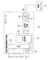
ここで、図2の構成において電池セル等が異常となった場合にはこれを検出して、異常信号を管理ユニット12に通知する異常検出回路101を図4に示すように設けることもできる。ただし、電池セル等の異常時には、電池セルからの電源電圧が供給されず、送受信回路22が異常信号の送信動作を行うことができない。そこで、図4に示すように、整流回路23から送受信回路27に直流電圧を供給可能にし、電池セル等の異常時には、送受信回路27では、整流回路23で整流した直流電圧で動作するようにする。
Here, when the battery cell or the like becomes abnormal in the configuration of FIG. 2, an
すなわち、図4において送受信回路27にVDD端子2を追加し、追加したVDD端子2を整流回路23のVDD端子と接続し、この状態において、スイッチ手段32をオンにすることにより整流回路23から送受信回路27に電源電圧が供給され、これにより送受信回路27は、電源セルから電源電圧が供給されないときでも動作可能になる。送受信回路27は整流回路23から電源電圧を取得する第2の電圧取得手段を含む。異常検出回路101は、電池セル等の異常を検出したら、異常信号を送受信回路27に送り、送受信回路27は、異常信号をトランス25を介して管理ユニット12に送信する。管理ユニット12は、受信した異常信号の内容を解析して、解析結果を外部に出力してもよい。
That is, the
異常検出回路101は、電池セル等の異常として、電池セルの端子間電圧が所定電圧より小さくなること、電池セルと電池情報取得回路21とを接続する配線の切断、電池セルの両端子の短絡との、大きく3つの異常検出機能を有するが、異常検出回路101が有するこれらの異常検出機能の詳細については後に詳述する。
The
図5は、電池情報取得回路21の詳細構成例を示す。
FIG. 5 shows a detailed configuration example of the battery
電池情報取得回路21は、上述のように入力端子21a、21bを介して電池セルの両端に接続され、電池セルの端子間電圧を取得する。また、電池情報取得回路21は、サーミスタ等の温度センサ51を備え、この温度センサ51により電池セルの温度を検出する。
The battery
A/D処理部52は、入力端子21a、21bを介して取得した電圧をディジタル信号に変換する。A/D処理部52は生成したディジタル信号を送受信回路22に渡し、送受信回路22はディジタル信号をトランス25を介して管理ユニット12に送信する。
The A /
ここで図6に示すように電池情報取得回路21に処理部53およびメモリー54をさらに備えさせる構成も可能である。処理部53は電池情報取得回路21全体を制御し、特に電池情報取得の制御を行う。メモリー54は、取得された電池情報を保存する。より詳細に、処理部53は、送受信回路22との間でデータを送受信し、送受信回路22を介して管理ユニット12からの送信指示命令を受けると、電池セルの電池情報を取得して送受信回路22に渡す制御を行う。この制御においては、まずA/D処理部52が、電池セルの端子間電圧と、温度センサの検出電圧とをそれぞれ取得し、これらの取得した電圧をそれぞれディジタル信号に変換する。次に処理部53は、これらのディジタル信号をディジタル処理ロジックによりディジタル処理して管理ユニット12に適したデータ形式にし、このデータ形式のデータをメモリー54で保存する。次に、処理部53は、メモリー54に保存されたデータを送受信回路22に渡し、送受信回路22はこのデータをトランス25を介して管理ユニット12に送信する。なおディジタル信号を上記データ形式へ変換することなく、管理ユニット12に送信するようにしてもよい。
Here, as shown in FIG. 6, the battery
ここまでの説明では、図1に示したように、1つの電池セルごとに、1つの電池情報取得モジュールを接続する例を示した。すなわち、直列に接続された複数(例としてN個)の各電池セルのそれぞれに電池情報取得モジュールを接続し、1個の電池情報取得モジュールで1個の電池セルの電池情報を取得し、管理ユニット12に送信した。これに対して、複数の電池セルからなるグループ毎に電池情報取得モジュールを接続し、1つの電池情報取得モジュールで当該グループに含まれる各電池セルの電池情報を取得し、管理ユニット12に送信することも可能である。
In the description so far, as shown in FIG. 1, an example in which one battery information acquisition module is connected to each battery cell has been shown. That is, a battery information acquisition module is connected to each of a plurality (for example, N) of battery cells connected in series, and battery information of one battery cell is acquired and managed by one battery information acquisition module. Sent to
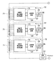
図7は、このように複数の電池セルからなるグループ毎に電池情報取得モジュールを接続する構成例を示す。 FIG. 7 shows a configuration example in which a battery information acquisition module is connected for each group of a plurality of battery cells.
直列接続された複数(N)個の電池セルが、それぞれM個(M<N)の電池セルからなる複数のグループ71に分けられ、グループ71毎に電池情報取得モジュール72が接続されている。各グループ内の電池セル数は同一であっても異なってもよい。電池情報取得モジュール72は、対応するグループ71に含まれる各電池セルから電池情報を取得して、管理ユニット12に送信する。
A plurality of (N) battery cells connected in series are divided into a plurality of
電池情報取得モジュール72は、多直列電池情報取得回路73、送受信回路22、トランス25、整流回路、起動回路、スイッチ手段等を備える。ただし整流回路、起動回路、スイッチ手段の図示は表記の簡単のため省略している。送受信回路22、トランス25、整流回路、起動回路、スイッチ手段は図2の同一名称の要素と同等の機能を有し、多直列電池情報取得回路73は、複数の電池セルからそれぞれ電池情報を取得する点を除いては、図2の電池情報取得回路21と同等の機能を有する。図3または図4に示した構成を図7の電池情報取得モジュールに対して採用することも可能である。
The battery
図7の構成と図1の構成とを比較すると、図1の構成では、電池情報取得回路21にかかる電圧は電池セル1個分となり、したがって高耐圧な部品や回路が必要なくなるという利点がある。一方、図7の構成では、電池情報取得回路73および送受信回路22にかかる電圧は電池セルM個分となるため、電池情報取得回路73および送受信回路22にかかる電圧は大きくなるものの、電池情報取得回路、送受信回路、トランスなどの部品点数を削減できるという利点がある。したがって電池情報取得モジュールの使用条件や使用状況に応じて適宜、適切な方の構成を採択するのがよい。
Comparing the configuration of FIG. 7 with the configuration of FIG. 1, the configuration of FIG. 1 has the advantage that the voltage applied to the battery
図8は図7における多直列電池情報取得回路73の詳細構成例を示す。
FIG. 8 shows a detailed configuration example of the multi-series battery
多直列電池情報取得回路73は温度センサ91、A/D処理部92、セレクタ(マルチプレクサ)95を備え、M個の電池セルと接続される。図6と同一名称の要素は基本的に同等の機能を有するため、以下では、図6に存在しないセレクタ95、ならびに図6と同一名称の要素の拡張された動作についてのみ説明する。なお、多直列電池情報取得回路73および送受信回路22には電源電圧としてM個の電池セルの両端間電圧(M個の電池セルのうちの図中上側端の電池セルのプラス端子と、図中下側端の電池セルのマイナス端子間の電圧)が与えられる。
The multi-series battery
セレクタ95は、M個の電池セルと接続され、各電池セルの端子間電圧を検出する。セレクタ95はM個の電池セルから1つを選択し、選択した電池セルの電圧を出力する。
The
また、温度センサ91は、M個の電池セルのいずれか1つの電池セルに対応して設けられ、この電池セルの温度が電池情報として検出される。検出された温度は、M個の電池セルの代表温度といえる。
The
セレクタ95で選択された電池セルの電圧、および上記検出された温度の電圧は、A/D処理部92に入力され、ディジタル信号へ変換される。このディジタル信号は送受信回路2に渡され、送受信回路22はこのディジタル信号をトランス25を介して管理ユニット12に送信する。
The voltage of the battery cell selected by the
ここでは温度センサを1つのみ配置しているが、2つ以上の温度センサと第2のセレクタとを配置し、第2のセレクタで温度センサを選択し、選択した温度センサの温度の電圧をA/D処理部92に入力するようにしてもよい。
Although only one temperature sensor is arranged here, two or more temperature sensors and a second selector are arranged, the temperature sensor is selected by the second selector, and the temperature voltage of the selected temperature sensor is set. The data may be input to the A /
ここで、図9に示すように、多直列電池情報取得回路73に処理部93およびメモリー94を備えさせてもよい。
Here, as shown in FIG. 9, the multi-series battery
処理部93は管理ユニット12からの送信指示命令に応じた電池セルを選択するようセレクタ95を制御する。セレクタ95は、処理部93からの指示に応じて、M個の電池セルから1つを選択し、選択した電池セルの電圧を出力する。処理部93は、選択した電池セルの電圧をA/D処理部52を介してディジタル信号として受け取り、このディジタル信号をディジタル処理して管理ユニット12に適したデータ形式に変換してメモリー94に格納する。処理部93はメモリー94からこのデータを読み出して送受信回路22に渡す。管理ユニット12からの送信指示には、たとえばM個の電池セルを1つずつ順番に選択する指示、またはM個の電池セルのうち特定の電池セルのみを1つずつ順番に選択する指示が含まれてもよい。
The
また、処理部93は管理ユニット12からの送信指示命令に応じて、温度センサ91により検出された温度の電圧を、A/D処理部92を介してディジタル信号として取得し、取得したディジタル信号をディジタル処理して管理ユニット12に適したデータ形式に変換してメモリー94に格納する。処理部93はメモリー94からこのデータを読み出して、送受信回路22に渡す。
Further, the
図10は、図4に示した異常検出回路(電圧比較回路、断線検知回路、短絡検知回路)101の構成例を示す。先に簡単に述べたように、異常検出回路101は大きく3つの機能を有する。
FIG. 10 shows a configuration example of the abnormality detection circuit (voltage comparison circuit, disconnection detection circuit, short circuit detection circuit) 101 shown in FIG. As described briefly above, the
(1)異常検出回路101の機能の1つ目は、電池セル1101の端子間電圧を所定電圧と比較し、端子間電圧が所定電圧を下回ったことを検出する機能である。電池情報取得回路21は電池セル1101の電圧により動作するが、電池セル1101の電圧が電池情報取得回路21の最低動作電圧よりも小さくなった場合、動作不能となり、電池セルの電池情報を正しく検知できなくなる。そこで、異常検出回路101では、電池情報取得回路21よりも最低動作電圧が低い回路、もしくは電池セル1101以外の電圧源を用いて動作する回路を用いて、電池セル1101の電圧が電池情報取得回路21の最低動作電圧を下回ったか否かを検査し、下回ったときは送受信回路22を介して、電池セル1101の電圧が電池情報取得回路の最低動作電圧を下回ったことを表す第1の異常信号を管理ユニット12に送信する。
(1) The first function of the
電池セル1101の端子間電圧を所定電圧と比較し端子間電圧が所定電圧を下回ったことを検知するには、図10に示すように、電池セル1101のマイナス端子に所定電圧(Vref)1102を加えた電圧と、電池セル1101のプラス端子の電圧とを比較器1103で比較すればよい。比較器1103からは、端子間電圧が所定電圧以上であればハイレベル信号が出力され、所定電圧未満であればローレベル信号(第1の異常信号)が出力される。比較器1103からの出力信号は送受信回路22を介して管理ユニット12に送信される。比較器1103はたとえば本発明の電圧比較回路に相当し、所定電圧1102は閾値電圧に相当する。
In order to compare the voltage between the terminals of the
(2)異常検出回路101の機能の2つ目は、電池セル1101の両端子が短絡したことを検知する機能である。前述したように電池情報取得回路21は電池セル1101の電圧により動作するため、電池セル1101の両端子が短絡して電位差がゼロになると電池情報取得回路21は動作不能になり、電池セルの電池情報を正しく検知できなくなる。そこで、異常検出回路101では、電池セル1101の両端子が短絡していないかを検知し、短絡を検知したときは、電池セル1101の両端子間の短絡発生を表す第2の異常信号を送受信回路22を介して管理ユニット12に送信する。
(2) The second function of the
電池セル1101の両端子間の短絡を検知するには、図10に示すように、電池セル1101の端子間電圧を比較器1106で比較すればよい。本例では、ここでは安定した動作を得るため、比較器1106として、2つの比較器1104a、1104bそれぞれに、比較器1104a、1104bのオフセット電圧よりも大きな電圧源(Voff)1105a、1106bを逆向きに接続したオフセットコンパレータを用いている。比較器1104a、1104bの出力信号は送受信回路22を介して管理ユニット12に送信される。短絡が生じていないときは比較器1104a、1104bからともにハイレベル信号が出力される(すなわち比較器1106から正常信号が出力される)。短絡が生じているときは、それ以外の組合せの信号(比較器1104a、1104bの少なくとも一方の出力がローレベル信号)が第2の異常信号として出力される。比較器1106はたとえば本発明の短絡検知回路に相当する。
In order to detect a short circuit between both terminals of the
(3)異常検出回路101の機能の3つ目は、電池セル1101と電池情報取得回路21を接続する接続配線1109が断線したことを検知する機能である。断線が起こった場合、電池情報取得回路21は動作しなくなり、電池セル1101の電池情報を正しく検知できなくなる。そこで、異常検出回路101では、断線が起こっていないか否かを検知し、断線の発生を検知したときは、断線の発生を表す第3の異常信号を送受信回路22を介して管理ユニット12に送信する。
(3) The third function of the
電池セル1101と電池情報取得回路21を接続する配線1109が断線したことを検知するには、前述の比較器(オフセットコンパレータ)1106の入力端子間に、スイッチ1107と抵抗1108とを直列に接続し、スイッチ1107のオンオフを定期的に繰り返し、オンのときの比較器1106の出力(すなわち比較器1104a、1104bの出力)を確認すればよい。電池セル1101との間の配線1109が断線していなければ、スイッチ1107をオンにすると抵抗1108にある一定の電圧が発生し、短絡が生じていないときと同様に比較器1104a、1104bからともにハイレベル信号が出力される(すなわち比較器1106から正常信号が出力される)。一方、電池セル1101との間の配線が断線していれば、抵抗1107に発生する電圧はゼロになり、この結果、比較器1104a、1104bからは短絡が生じているときと同様、比較器1104a、1104bの少なくとも一方からローレベル信号が出力される。このときの比較器1104a、1104bの出力信号の組(比較器1106の出力信号)は第3の異常信号に相当する。抵抗1108とスイッチ1107と比較器1106の組は本発明の断線検知回路に相当する。
To detect that the wiring 1109 connecting the
なおもしスイッチ1107がオフに固定されていると、断線が生じたとき、電池セル1101の両端にそれぞれ接続される配線間の寄生容量により比較器1106の各入力端子には一定の電圧が発生するため比較器1106からは正常信号が出力され断線を検出できない。しかし、断線後にスイッチ1107をいったんオンにすると、寄生容量の電荷が放電され、抵抗1107に発生する電圧がゼロになり(すなわち配線間の電圧がゼロになり)、このため断線の検出が可能になる。
If the
図11および図12は、図6および図9に示すA/D処理部の詳細構成例をそれぞれ示す。 11 and 12 show detailed configuration examples of the A / D processing unit shown in FIGS. 6 and 9, respectively.
A/D処理部の電源電圧として、電池セルの電圧を用いているため、A/D処理部は自身の電源電圧と等しい電圧をA/D変換する必要がある。ただし図3のようにDC−DC変換した電圧(ここでは電池セルの電圧よりも低いとする)をA/D処理部の電源電圧として用いる場合は、DC−DC変換電圧よりも大きな電圧をA/D変換する必要がある。図11は入力電圧範囲と分解能を可変にしてA/D処理部自身の電源電圧よりも大きな電圧も直接A/D変換する構成例を示す。図12は入力電圧を分圧して入力電圧範囲が固定のA/D変換器(ADC)によりA/D変換する構成例を示す。 Since the voltage of the battery cell is used as the power supply voltage of the A / D processing unit, the A / D processing unit needs to A / D convert a voltage equal to its own power supply voltage. However, when a DC-DC converted voltage (here, lower than the voltage of the battery cell) is used as the power supply voltage of the A / D processing unit as shown in FIG. 3, a voltage larger than the DC-DC converted voltage is A / D conversion is required. FIG. 11 shows a configuration example in which the input voltage range and resolution are made variable, and a voltage larger than the power supply voltage of the A / D processing unit itself is directly A / D converted. FIG. 12 shows a configuration example in which an input voltage is divided and A / D conversion is performed by an A / D converter (ADC) having a fixed input voltage range.
図11では、電池セル2301と温度センサ2302とを並列に接続し、スイッチ2303の切り替えにより、電池セル2301の端子間電圧と温度センサ2302の検出電圧うちの一方を選択的にA/D変換器2304に入力する。入力された電圧は直列接続した2N+1個の抵抗(抵抗手段)2305で2N通りの電圧に分割され、2N個の比較器(比較手段)2306に入力される。ここで、NはA/D変換器2304のビット数である。各比較器2306のもう一方の入力には、基準電圧(Vref)2307が入力される。
In FIG. 11, the
各比較器2306では入力された分圧電圧と基準電圧(Vref)2307とが比較され、これらの大小関係を表す信号がそれぞれ出力される。たとえば入力された分圧電圧が基準電圧(Vref)2307より大きいときはハイレベル信号が出力され、基準電圧(Vref)2307以下のときはローレベル信号が出力される。
Each
各比較器2306の出力信号はエンコーダ(電圧データ生成手段)2308に入力され、エンコーダ2308は、A/D処理部への入力電圧が基準電圧の何倍に相当するかを示すディジタルコード(電圧データ)を出力する。つまり、電池セル2301の電圧が基準電圧2307よりも大きいと仮定すると、分圧電圧が、基準電圧2307よりも小さくなったところで比較器206の出力内容が切り替わるため、この切り替わりの位置に応じて、電池セル2301の電圧が基準電圧2307の何倍であるかを検出できる。入力電圧範囲は基準電圧から基準電圧の2N倍まで可変である。
The output signal of each
電池セル2301の電圧と温度センサ2302の電圧が大きく異なる場合は基準電圧を2種類用意し、スイッチ2303と連動して、使用する基準電圧を切り替えることも可能である。
When the voltage of the
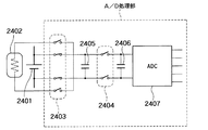
図12では、電池セル2401と温度センサ2402とを並列に接続し、スイッチ2403の切り替えにより、電池セル2401の端子間電圧と温度センサ2402の検出電圧のうちの一方を選択する。選択された電圧を降圧するために、まずスイッチ2404をオフにして電圧を容量2405に充電し、充電に必要な所定の期間後、スイッチ2403をオフにしてスイッチ2404をオンする。すると容量2405に充電された電荷は容量2405と容量2406に再分配される。容量2405、2406およびスイッチ2404は本発明の電圧分割手段に相当する。
In FIG. 12, the
容量2405と容量2406の比を1:(N-1)とすると、容量2406の電圧は、電池セル2401の端子間電圧もしくは温度センサ2402の検出電圧の1/Nに相当する。この電圧をA/D変換器2407でディジタル信号に変換する。温度センサ2402の検出電圧がA/D変換器2407の入力電圧範囲の上限よりも小さい場合は、スイッチ2403とスイッチ2404をオンし、温度センサ2402の検出電圧を、降圧することなく、直接A/D変換器2407に入力することも可能である。
When the ratio of the
図13は、図2〜図4に示した整流回路の構成例を示す。 FIG. 13 shows a configuration example of the rectifier circuit shown in FIGS.
この整流回路は4つのダイオード2501a〜2501dと、容量2502とからなるダイオードブリッジである。トランス25の2次側巻線にダイオードブリッジのT1P端子およびT1N端子が接続される(図2参照)。管理ユニット12から送信される交流信号がダイオード2501a〜2501dにより整流され、容量2501にて平滑される。平滑された直流電圧はVDD端子およびGND端子を介して起動回路24へ電源電圧として供給される。
This rectifier circuit is a diode bridge composed of four
ここで、図1に示したように、各電池情報取得モジュールは互いに並列に共通配線に接続されるため、ある電池情報取得モジュールから管理ユニット12への送信時に、送信信号が他の電池情報取得モジュール内の整流回路に入力され、これにより当該整流回路が駆動してしまう場合がある。この問題に対しては、電池情報取得モジュールの受信時および送信時それぞれで、信号振幅レベルを変えることで解決できる。
Here, as shown in FIG. 1, each battery information acquisition module is connected to the common wiring in parallel with each other, and therefore, when a transmission from one battery information acquisition module to the
具体的には、電池情報取得モジュールの受信時は、すべての電池情報取得モジュール内の整流回路(ダイオードブリッジ)を駆動するため、すべてのダイオードブリッジがオンするような信号振幅レベル(すなわちダイオードの閾値電圧(所定値)以上の信号振幅レベル)で、管理ユニット12から信号を出力する。一方、電池情報取得モジュールからの送信時は、最大振幅が他の電池情報取得モジュールの整流回路がオンしないレベルの信号(電池情報)を管理ユニット12に送る。これにより、電池情報取得モジュールからの送信時に他の電池情報取得モジュール内の整流回路の駆動は阻止され、また当該電池情報取得モジュール内の送受信回路22からの送信信号により同モジュール内の整流回路23が駆動されるのも阻止できる。このように整流回路が不必要に駆動されるのを阻止することで、電力の効率的な使用が図れる。
Specifically, when receiving the battery information acquisition module, the rectifier circuit (diode bridge) in all the battery information acquisition modules is driven, so that the signal amplitude level (that is, the diode threshold value) that turns on all the diode bridges. A signal is output from the
これまでは、1つの1次側巻線と1つの2次側巻線とを有するトランス(1次側差動2入力かつ2次側差動2出力のトランス)を前提に説明をしてきたが、1つの一次側巻線と2つの2次側巻線とを有するトランス(1次側差動2入力かつ2次側差動4出力のトランス)を用いてもよい。図14に1つの1次側巻線と2つの2次側巻線とを有するトランス(2入力4出力のトランス)を用いた電池情報管理システムの構成例を示す。ただしここでは、説明の簡単のため、1つの電池セルと、当該1つの電池セルに接続された電池取得電池情報取得モジュールのみを示す。
So far, the explanation has been made on the premise of a transformer having one primary side winding and one secondary side winding (transformer with
トランス35は、1つの1次側巻線36と、2つの2次側巻線37a、37bとを有する。2次側巻線(一方の2次側巻線)37aは送受信回路22に、2次側巻線(他方の2次側巻線)37bは、整流回路23と起動回路24とに接続される。このとき、整流回路23へは起動回路24の駆動のための電力を伝送するので、2次側巻線37bと1次側巻線36の結合係数を大きめに設定し、送受信回路22へは信号を伝送するので、2次側巻線37aと1次側巻線36との結合係数は少なめに設定することも可能である。なお図15の例では起動回路24は2次側巻線37bに接続されているが、起動回路24は2次側巻線37aに接続されてもよい。
The transformer 35 has one primary winding 36 and two
なお、本発明は上記実施形態そのままに限定されるものではなく、実施段階ではその要旨を逸脱しない範囲で構成要素を変形して具体化できる。また、上記実施形態に開示されている複数の構成要素の適宜な組み合わせにより、種々の発明を形成できる。例えば、実施形態に示される全構成要素から幾つかの構成要素を削除してもよい。さらに、異なる実施形態にわたる構成要素を適宜組み合わせてもよい。 Note that the present invention is not limited to the above-described embodiment as it is, and can be embodied by modifying the constituent elements without departing from the scope of the invention in the implementation stage. In addition, various inventions can be formed by appropriately combining a plurality of components disclosed in the embodiment. For example, some components may be deleted from all the components shown in the embodiment. Furthermore, constituent elements over different embodiments may be appropriately combined.
11:組電池
12:管理ユニット
13:電池情報取得モジュール(電池情報取得装置)
20a、20b:電圧取得手段
21a、21b:入力端子(電圧入力手段)
21:電池情報取得回路
22、27:送受信回路
23:整流回路
24:起動回路
25:トランス
31、32:スイッチ手段
36:1次側巻線
37、37a、37b:2次側巻線
41:電源回路
51:温度センサ
52:A/D処理部
53:処理部
54:メモリー
73:電池情報取得回路
75:トランス
91:温度センサ
93:処理部
94:メモリー
98:セレクタ
101:異常検出回路(電圧比較回路、断線検知回路、短絡検知回路)
1101電池セル
1119:共通配線
1102:所定電圧
1106、1104a、1104b、1103:比較器
1105a、1106b:電圧源
1107:スイッチ
1108:抵抗
2301:電池セル
2302:温度センサ
2303:スイッチ
2304:A/D変換器
2306:比較器
2308:エンコーダ(電圧データ生成手段)
2305:抵抗
2307:基準電圧(Vref)
2401:電池セル
2402:温度センサ
2405、2406:容量(電圧分割手段)
2403、2404:スイッチ
2407:A/D変換器
2501a〜2504d:ダイオード
2502:容量
11: assembled battery 12: management unit 13: battery information acquisition module (battery information acquisition device)
20a, 20b: voltage acquisition means 21a, 21b: input terminals (voltage input means)
21: Battery
1101 battery cell 1119: common wiring 1102: predetermined voltage
1106, 1104a, 1104b, 1103:
1107: Switch 1108: Resistance 2301: Battery cell 2302: Temperature sensor 2303: Switch 2304: A / D converter 2306: Comparator 2308: Encoder (voltage data generation means)
2305: Resistor 2307: Reference voltage (Vref)
2401: Battery cell 2402:
2403, 2404: Switch 2407: A /
Claims (16)
前記電池セルの端子間電圧を取得する電圧取得手段と、
前記電圧取得手段による取得電圧が電源電圧として供給され、前記電池セルから電池情報を取得する電池情報取得回路と、
前記共通配線に接続された1次側巻線と、2次側巻線と、を有するトランスと、
前記トランスの2次側巻線に接続され、前記取得電圧が電源電圧として供給され、前記電池情報の信号を前記トランスを介して前記管理ユニットに送信する通信回路と、
前記トランスの2次側巻線に接続され、前記管理ユニットから送信される所定周波数の信号を前記トランスを介して受信し、受信した前記信号を整流して直流電圧を生成する整流回路と、
前記トランスの2次側巻線に接続され、前記整流回路により生成された直流電圧が電源電圧として供給され、前記電池情報取得回路および前記通信回路に対する前記電源電圧の供給を制御する制御回路と、を備え、
前記制御回路は、
前記電池情報取得回路に対する前記電源電圧の供給の有無を指示する第1指示信号を前記管理ユニットから前記トランスを介して受信する第1の受信手段と、
前記通信回路に対する前記電源電圧の供給の有無を指示する第2指示信号を前記管理ユニットから前記トランスを介して受信する第2の受信手段と、
前記第1指示信号に応じて前記電池情報取得回路に対する前記電源電圧の供給の有無を切り替え制御する第1の切替制御手段と、
前記第2指示信号に応じて前記通信回路に対する前記電源電圧の供給の有無を切り替え制御する第2の切替制御手段と、
を備えた電池情報取得装置。 The battery information of the battery cell in an assembled battery in which a plurality of battery cells are connected in series is acquired, and the acquired battery information is sent to a management unit that manages the state of the assembled battery. A battery information acquisition device that transmits via a common wiring connected in common with other battery information acquisition devices for acquiring battery information of a cell,
Voltage acquisition means for acquiring a voltage between terminals of the battery cell;
A battery information acquisition circuit for acquiring battery information from the battery cell, wherein the acquisition voltage by the voltage acquisition means is supplied as a power supply voltage;
A transformer having a primary winding connected to the common wiring and a secondary winding;
A communication circuit connected to the secondary winding of the transformer, the acquired voltage being supplied as a power supply voltage, and transmitting the battery information signal to the management unit via the transformer;
A rectifier circuit connected to the secondary winding of the transformer, receiving a signal of a predetermined frequency transmitted from the management unit via the transformer, and rectifying the received signal to generate a DC voltage;
A control circuit connected to the secondary winding of the transformer, supplied with a DC voltage generated by the rectifier circuit as a power supply voltage, and controlling the supply of the power supply voltage to the battery information acquisition circuit and the communication circuit; With
The control circuit includes:
First receiving means for receiving from the management unit via the transformer a first instruction signal instructing whether or not to supply the power supply voltage to the battery information acquisition circuit;
Second receiving means for receiving a second instruction signal for instructing whether or not the power supply voltage is supplied to the communication circuit from the management unit via the transformer;
First switching control means for switching the presence or absence of supply of the power supply voltage to the battery information acquisition circuit according to the first instruction signal;
Second switching control means for switching the presence or absence of supply of the power supply voltage to the communication circuit in response to the second instruction signal;
A battery information acquisition device comprising:
前記電池情報取得回路および前記通信回路に、前記取得された端子間電圧をDC−DC変換した電圧を前記電源回路から電源電圧として供給する
ことを特徴とする請求項1に記載の電池情報取得装置。 A power supply circuit for DC-DC converting the acquired inter-terminal voltage;
The battery information acquisition apparatus according to claim 1, wherein a voltage obtained by DC-DC conversion of the acquired inter-terminal voltage is supplied from the power supply circuit to the battery information acquisition circuit and the communication circuit as a power supply voltage. .
前記電池セルの端子間電圧を入力する電圧入力手段と、前記電池セルの温度を検出する温度センサと、A/D処理部とを有し、
前記A/D処理部は、前記電圧入力手段を介して前記電池セルの端子間電圧である第1電圧を取得し、前記温度センサを介して前記電池セルの温度を表す第2電圧を取得し、前記第1および第2電圧をそれぞれディジタル信号に変換して前記通信回路に送出する
ことを特徴とする請求項4に記載の電池情報取得装置。 The battery information acquisition means includes
Voltage input means for inputting the voltage between the terminals of the battery cell, a temperature sensor for detecting the temperature of the battery cell, and an A / D processing unit,
The A / D processing unit acquires a first voltage that is a voltage between the terminals of the battery cell via the voltage input unit, and acquires a second voltage that represents the temperature of the battery cell via the temperature sensor. The battery information acquisition apparatus according to claim 4, wherein the first and second voltages are converted into digital signals and sent to the communication circuit.
前記直列接続されたM個の電池セルの両端間電圧を電源電圧として前記電池情報取得回路および前記通信回路に供給する、
ことを特徴とする請求項1または2に記載の電池情報取得装置。 The battery information acquisition unit acquires, as the battery information, voltages of M (M is an integer of 2 or more) battery cells connected in series and at least one temperature of the M battery cells. And
Supplying the voltage across the M battery cells connected in series as a power supply voltage to the battery information acquisition circuit and the communication circuit;
The battery information acquisition apparatus according to claim 1, wherein the battery information acquisition apparatus is a battery information acquisition apparatus.
前記M個の電池セルの各々の端子間電圧を入力する複数の電圧入力手段と、前記複数の電圧入力手段のうちから1つを選択するセレクタと、前記少なくとも1つの電池セルの温度を検出する温度センサと、A/D処理部とを有し、
前記A/D処理部は、前記セレクタによって選択した電圧入力手段に対応する電圧である第1電圧を取得し、前記温度センサを介して前記電池セルの温度を表す第2電圧を取得し、前記第1および第2電圧をそれぞれディジタル信号に変換して前記通信回路に送出する
ことを特徴とする請求項5に記載の電池情報取得装置。 The battery information acquisition means includes
A plurality of voltage input means for inputting a voltage between terminals of each of the M battery cells; a selector for selecting one of the plurality of voltage input means; and a temperature of the at least one battery cell. A temperature sensor and an A / D processing unit;
The A / D processing unit acquires a first voltage that is a voltage corresponding to the voltage input unit selected by the selector, acquires a second voltage representing the temperature of the battery cell via the temperature sensor, and The battery information acquisition apparatus according to claim 5, wherein the first voltage and the second voltage are each converted into a digital signal and sent to the communication circuit.
前記第1または第2電圧を分割する直列接続された複数の抵抗手段と、
前記複数の抵抗手段の各々の一端の電圧を基準電圧と比較し、各前記一端の電圧と前記基準電圧との大小関係を表す比較信号をそれぞれ生成する比較手段と、
各比較信号に基づいて前記第1または前記第2電圧を表す電圧データを生成し、生成した電圧データを前記通信回路に送出する電圧データ生成手段と、
を備えたことを特徴とする請求項4または6に記載の電池情報取得装置。 The A / D processing unit
A plurality of series-connected resistance means for dividing the first or second voltage;
Comparison means for comparing a voltage at one end of each of the plurality of resistance means with a reference voltage, and generating a comparison signal representing a magnitude relationship between the voltage at each one end and the reference voltage,
Voltage data generating means for generating voltage data representing the first or second voltage based on each comparison signal and sending the generated voltage data to the communication circuit;
The battery information acquisition device according to claim 4, comprising:
前記第1または第2電圧を、並列接続された複数の容量により分割する電圧分割手段と、
前記複数の容量のうちあらかじめ定められた容量にかかる電圧をA/D変換して前記通信回路に送出するA/D変換器と
を備えたことを特徴とする請求項4または6に記載の電池情報取得装置。 The A / D processing unit
Voltage dividing means for dividing the first or second voltage by a plurality of capacitors connected in parallel;
The battery according to claim 4, further comprising: an A / D converter that performs A / D conversion on a voltage applied to a predetermined capacity among the plurality of capacitors and sends the voltage to the communication circuit. Information acquisition device.
前記通信回路は、前記ID情報と前記電池情報とを含む信号を前記管理ユニットに送信する
ことを特徴とする請求項1ないし8のいずれか一項に記載の電池情報取得装置。 The communication circuit has unique ID information;
The battery information acquisition device according to any one of claims 1 to 8, wherein the communication circuit transmits a signal including the ID information and the battery information to the management unit.
前記電圧比較回路は、前記電池セルの端子間電圧が前記閾値電圧を下回ったときは第1の異常信号を前記通信回路に送り、
前記通信回路は、前記第1の異常信号を前記トランスを介して前記管理ユニットに送信する
ことを特徴とする請求項1ないし9のいずれか一項に記載の電池情報取得装置。 A voltage comparison circuit for comparing the voltage between the terminals of the battery cell with a threshold voltage;
When the voltage between the terminals of the battery cell falls below the threshold voltage, the voltage comparison circuit sends a first abnormality signal to the communication circuit,
The battery information acquisition device according to any one of claims 1 to 9, wherein the communication circuit transmits the first abnormality signal to the management unit via the transformer.
前記断線検知回路は、断線の発生を検知したときは第2の異常信号を前記通信回路に送り、
前記通信回路は、前記第2の異常信号を前記トランスを介して前記管理ユニットに送信する
ことを特徴とする請求項1ないし10のいずれか一項に記載の電池情報取得装置。 Further comprising a disconnection detection circuit for detecting disconnection of the connection wiring between the battery cell and the battery information acquisition circuit;
The disconnection detection circuit sends a second abnormal signal to the communication circuit when the occurrence of disconnection is detected,
The battery information acquisition device according to any one of claims 1 to 10, wherein the communication circuit transmits the second abnormality signal to the management unit via the transformer.
前記短絡検知回路は、前記両端子の短絡を検知したときは第3の異常信号を前記通信回路に送り、
前記通信回路は、前記第3の異常信号を前記トランスを介して前記管理ユニットに送信する
ことを特徴とする請求項1ないし11のいずれか一項に記載の電池情報取得装置。 Further comprising a short circuit detection circuit for detecting a short circuit of both terminals of the battery cell,
The short circuit detection circuit sends a third abnormality signal to the communication circuit when it detects a short circuit of both terminals,
The battery information acquisition device according to any one of claims 1 to 11, wherein the communication circuit transmits the third abnormality signal to the management unit via the transformer.
前記通信回路は、前記電圧取得手段からの前記取得電圧の供給が途絶えたとき、前記第2の電圧取得手段により取得された電源電圧を用いて動作する
ことを特徴とする請求項10ないし12のいずれか一項に記載の電池情報取得装置。 The communication circuit has second voltage acquisition means for acquiring the generated DC voltage from the rectifier circuit as a power supply voltage,
The communication circuit operates using the power supply voltage acquired by the second voltage acquisition means when the supply of the acquisition voltage from the voltage acquisition means is interrupted. The battery information acquisition device according to any one of the above.
前記通信回路は、前記所定値よりも低い振幅レベルの信号を前記管理ユニットに送信し、
前記管理ユニットからは、前記所定値より大きい振幅レベルの信号が送信される、
ことを特徴とする請求項1ないし13のいずれか一項に記載の電池情報取得装置。 The rectifier circuit performs rectification when a signal having an amplitude level greater than or equal to a predetermined value is input, does not perform rectification when a signal having an amplitude level lower than the predetermined value is input,
The communication circuit transmits a signal having an amplitude level lower than the predetermined value to the management unit;
A signal having an amplitude level greater than the predetermined value is transmitted from the management unit.
The battery information acquisition device according to claim 1, wherein the battery information acquisition device is a battery information acquisition device.
前記所定値は、前記複数のダイオードの閾値電圧を表す
ことを特徴とする請求項14に記載の電池情報取得装置。 The rectifier circuit has a diode bridge configuration including a plurality of diodes,
The battery information acquiring apparatus according to claim 14, wherein the predetermined value represents a threshold voltage of the plurality of diodes.
前記通信回路は前記2つの2次側巻線の一方に接続され、前記整流回路は前記2つの2次側巻線の他方に接続され、前記制御回路は、前記2つの2次側巻線の一方または他方に接続され、
前記他方の2次側巻線と前記1次側巻線との結合係数は、前記一方の2次側巻線と前記1次側巻線との結合係数よりも大きい
ことを特徴とする請求項1ないし15のいずれか一項に記載の電池情報取得装置。 The transformer has two secondary windings;
The communication circuit is connected to one of the two secondary windings, the rectifier circuit is connected to the other of the two secondary windings, and the control circuit is connected to the two secondary windings. Connected to one or the other,
The coupling coefficient between the other secondary winding and the primary winding is larger than the coupling coefficient between the one secondary winding and the primary winding. The battery information acquisition device according to any one of 1 to 15.
Priority Applications (2)
| Application Number | Priority Date | Filing Date | Title |
|---|---|---|---|
| JP2008248691A JP5355979B2 (en) | 2008-09-26 | 2008-09-26 | Battery information acquisition device |
| US12/406,534 US8058878B2 (en) | 2008-09-26 | 2009-03-18 | Battery information acquiring apparatus |
Applications Claiming Priority (1)
| Application Number | Priority Date | Filing Date | Title |
|---|---|---|---|
| JP2008248691A JP5355979B2 (en) | 2008-09-26 | 2008-09-26 | Battery information acquisition device |
Publications (2)
| Publication Number | Publication Date |
|---|---|
| JP2010081756A true JP2010081756A (en) | 2010-04-08 |
| JP5355979B2 JP5355979B2 (en) | 2013-11-27 |
Family
ID=42056721
Family Applications (1)
| Application Number | Title | Priority Date | Filing Date |
|---|---|---|---|
| JP2008248691A Expired - Fee Related JP5355979B2 (en) | 2008-09-26 | 2008-09-26 | Battery information acquisition device |
Country Status (2)
| Country | Link |
|---|---|
| US (1) | US8058878B2 (en) |
| JP (1) | JP5355979B2 (en) |
Cited By (13)
| Publication number | Priority date | Publication date | Assignee | Title |
|---|---|---|---|---|
| JP2011222309A (en) * | 2010-04-09 | 2011-11-04 | Ihi Corp | Power source monitoring control apparatus |
| EP2565959A2 (en) | 2011-08-31 | 2013-03-06 | Sony Corporation | Power storage apparatus and electric vehicle |
| JP2013238472A (en) * | 2012-05-15 | 2013-11-28 | Renesas Electronics Corp | Semiconductor device and voltage measurement device |
| JPWO2012124221A1 (en) * | 2011-03-14 | 2014-07-17 | 三洋電機株式会社 | Communication system and storage battery system |
| JP2015059762A (en) * | 2013-09-17 | 2015-03-30 | 株式会社東芝 | Battery pack module, and wire disconnection detecting method |
| JP2015061333A (en) * | 2013-09-17 | 2015-03-30 | 株式会社東芝 | Device and system for battery monitoring |
| JPWO2013094015A1 (en) * | 2011-12-20 | 2015-04-27 | 日立オートモティブシステムズ株式会社 | Battery monitoring / control integrated circuit and battery system |
| JP2015136289A (en) * | 2011-12-20 | 2015-07-27 | 日立オートモティブシステムズ株式会社 | Integrated circuit for battery monitoring and control and battery system |
| JP2015220812A (en) * | 2014-05-15 | 2015-12-07 | 株式会社ケーヒン | Voltage detector |
| JP2016012510A (en) * | 2014-06-30 | 2016-01-21 | 株式会社今仙電機製作所 | Voltage monitoring and voltage equalizing device for serial storage battery cell |
| JP2016144285A (en) * | 2015-01-30 | 2016-08-08 | 株式会社東芝 | Storage battery device, control method and program |
| JP2018189466A (en) * | 2017-05-01 | 2018-11-29 | ラピスセミコンダクタ株式会社 | Semiconductor device, battery monitoring system, and method for activating semiconductor device |
| WO2020129577A1 (en) * | 2018-12-17 | 2020-06-25 | パナソニックセミコンダクターソリューションズ株式会社 | Battery monitoring control circuit |
Families Citing this family (17)
| Publication number | Priority date | Publication date | Assignee | Title |
|---|---|---|---|---|
| DE102009054820A1 (en) * | 2009-12-17 | 2011-06-22 | Robert Bosch GmbH, 70469 | Energy storage system and method for its operation |
| FR2959066B1 (en) * | 2010-04-20 | 2013-02-22 | Saft Groupe Sa | SYSTEM AND METHOD FOR ELECTRONIC MANAGEMENT OF A RECHARGEABLE BATTERY |
| WO2012085562A1 (en) * | 2010-12-22 | 2012-06-28 | Trw Limited | Battery condition monitoring |
| WO2012114949A1 (en) * | 2011-02-23 | 2012-08-30 | ソニー株式会社 | Communication device, communication method, battery device, and electronic device |
| US10044074B2 (en) * | 2011-03-18 | 2018-08-07 | Johnson Controls Technology Company | Battery power source control and current detection systems and methods |
| DE102011102102A1 (en) * | 2011-05-20 | 2012-11-22 | GM Global Technology Operations LLC (n. d. Gesetzen des Staates Delaware) | accumulator |
| US9252631B2 (en) * | 2011-06-08 | 2016-02-02 | Andrew V. Latham | Data center battery enhancement method and system |
| DE102011082937A1 (en) * | 2011-09-19 | 2013-03-21 | Sb Limotive Company Ltd. | Battery management system, battery, motor vehicle with battery management system and method for monitoring a battery |
| JP5808418B2 (en) * | 2011-10-07 | 2015-11-10 | 日立オートモティブシステムズ株式会社 | Battery monitoring device, battery monitoring system |
| FR2986392B1 (en) | 2012-01-31 | 2016-05-06 | Renault Sa | COMMUNICATION SYSTEM IN AN ELECTRIC BATTERY |
| KR101816978B1 (en) * | 2012-11-19 | 2018-01-09 | 비와이디 컴퍼니 리미티드 | Protective device and protective system for battery assembly |
| US20140266230A1 (en) * | 2013-03-15 | 2014-09-18 | Philadelphia Scientific Llc | Battery Electrolyte Level Monitor |
| JP6160532B2 (en) * | 2014-03-26 | 2017-07-12 | 株式会社豊田自動織機 | Battery monitoring device |
| NL2013271B1 (en) * | 2014-07-28 | 2016-09-09 | E-Traction Europe B V | Electrical installation having high and low voltage circuits with common ground reference. |
| US10486542B2 (en) * | 2017-07-12 | 2019-11-26 | Ford Global Technologies, Llc | Battery thermal conditioning pump control for electric vehicle |
| KR102530221B1 (en) * | 2017-11-28 | 2023-05-09 | 삼성전자주식회사 | Method and apparatus for managing battery |
| CN110416642B (en) * | 2019-07-30 | 2022-05-31 | 四川长虹电器股份有限公司 | Brand protection system with disposable replaceable battery |
Citations (4)
| Publication number | Priority date | Publication date | Assignee | Title |
|---|---|---|---|---|
| JP2000014027A (en) * | 1998-06-23 | 2000-01-14 | Hitachi Ltd | Control device for capacitor |
| JP2003164001A (en) * | 2001-11-29 | 2003-06-06 | Nissan Motor Co Ltd | Cell voltage detector |
| JP2003294816A (en) * | 2002-04-03 | 2003-10-15 | Nagano Japan Radio Co | Voltage detector for storage battery |
| JP2005261193A (en) * | 2005-03-18 | 2005-09-22 | Nissan Motor Co Ltd | Voltage detector for battery pack for motor vehicle |
Family Cites Families (4)
| Publication number | Priority date | Publication date | Assignee | Title |
|---|---|---|---|---|
| JPH11345622A (en) | 1998-05-31 | 1999-12-14 | Aisin Seiki Co Ltd | Fuel cell generating set |
| WO2006090472A1 (en) * | 2005-02-25 | 2006-08-31 | Olympus Corporation | Device to be introduced into subject, and radio-type system for acquiring information inside subject |
| KR100818519B1 (en) * | 2006-05-04 | 2008-03-31 | 주식회사 엘지화학 | Method and apparatus of controlling battery |
| KR100814884B1 (en) * | 2006-10-16 | 2008-03-20 | 삼성에스디아이 주식회사 | Battery management system and driving method thereof |
-
2008
- 2008-09-26 JP JP2008248691A patent/JP5355979B2/en not_active Expired - Fee Related
-
2009
- 2009-03-18 US US12/406,534 patent/US8058878B2/en not_active Expired - Fee Related
Patent Citations (4)
| Publication number | Priority date | Publication date | Assignee | Title |
|---|---|---|---|---|
| JP2000014027A (en) * | 1998-06-23 | 2000-01-14 | Hitachi Ltd | Control device for capacitor |
| JP2003164001A (en) * | 2001-11-29 | 2003-06-06 | Nissan Motor Co Ltd | Cell voltage detector |
| JP2003294816A (en) * | 2002-04-03 | 2003-10-15 | Nagano Japan Radio Co | Voltage detector for storage battery |
| JP2005261193A (en) * | 2005-03-18 | 2005-09-22 | Nissan Motor Co Ltd | Voltage detector for battery pack for motor vehicle |
Cited By (18)
| Publication number | Priority date | Publication date | Assignee | Title |
|---|---|---|---|---|
| JP2011222309A (en) * | 2010-04-09 | 2011-11-04 | Ihi Corp | Power source monitoring control apparatus |
| JPWO2012124221A1 (en) * | 2011-03-14 | 2014-07-17 | 三洋電機株式会社 | Communication system and storage battery system |
| EP2565959A2 (en) | 2011-08-31 | 2013-03-06 | Sony Corporation | Power storage apparatus and electric vehicle |
| US9231280B2 (en) | 2011-08-31 | 2016-01-05 | Sony Corporation | Power storage apparatus and electric vehicle |
| JP2015136289A (en) * | 2011-12-20 | 2015-07-27 | 日立オートモティブシステムズ株式会社 | Integrated circuit for battery monitoring and control and battery system |
| JPWO2013094015A1 (en) * | 2011-12-20 | 2015-04-27 | 日立オートモティブシステムズ株式会社 | Battery monitoring / control integrated circuit and battery system |
| JP2013238472A (en) * | 2012-05-15 | 2013-11-28 | Renesas Electronics Corp | Semiconductor device and voltage measurement device |
| US9515503B2 (en) | 2013-09-17 | 2016-12-06 | Kabushiki Kaisha Toshiba | Battery monitoring device and battery monitoring system |
| JP2015061333A (en) * | 2013-09-17 | 2015-03-30 | 株式会社東芝 | Device and system for battery monitoring |
| JP2015059762A (en) * | 2013-09-17 | 2015-03-30 | 株式会社東芝 | Battery pack module, and wire disconnection detecting method |
| JP2015220812A (en) * | 2014-05-15 | 2015-12-07 | 株式会社ケーヒン | Voltage detector |
| JP2016012510A (en) * | 2014-06-30 | 2016-01-21 | 株式会社今仙電機製作所 | Voltage monitoring and voltage equalizing device for serial storage battery cell |
| JP2016144285A (en) * | 2015-01-30 | 2016-08-08 | 株式会社東芝 | Storage battery device, control method and program |
| JP2018189466A (en) * | 2017-05-01 | 2018-11-29 | ラピスセミコンダクタ株式会社 | Semiconductor device, battery monitoring system, and method for activating semiconductor device |
| JP7006876B2 (en) | 2017-05-01 | 2022-01-24 | ラピスセミコンダクタ株式会社 | Semiconductor devices, battery monitoring systems, and how to start semiconductor devices |
| WO2020129577A1 (en) * | 2018-12-17 | 2020-06-25 | パナソニックセミコンダクターソリューションズ株式会社 | Battery monitoring control circuit |
| US11824390B2 (en) | 2018-12-17 | 2023-11-21 | Nuvoton Technology Corporation Japan | Battery monitoring system provided with battery monitoring control circuit for reducing consumption power in sleep state |
| JP7458326B2 (en) | 2018-12-17 | 2024-03-29 | ヌヴォトンテクノロジージャパン株式会社 | Battery monitoring control circuit |
Also Published As
| Publication number | Publication date |
|---|---|
| US20100079146A1 (en) | 2010-04-01 |
| JP5355979B2 (en) | 2013-11-27 |
| US8058878B2 (en) | 2011-11-15 |
Similar Documents
| Publication | Publication Date | Title |
|---|---|---|
| JP5355979B2 (en) | Battery information acquisition device | |
| JP2010081716A (en) | Battery information obtaining device | |
| US7800346B2 (en) | Device and method for equalizing charges of series-connected energy stores | |
| KR101390641B1 (en) | System and method for converting electric power, and apparatus and method for controlling the system | |
| WO2013051157A1 (en) | Battery monitoring system, host controller, and battery monitoring device | |
| JP5910791B2 (en) | DC power supply | |
| US11824390B2 (en) | Battery monitoring system provided with battery monitoring control circuit for reducing consumption power in sleep state | |
| JP2005315853A (en) | Power supply | |
| US11290027B1 (en) | Wireless charging receiver circuit and chip, and wireless charging receiver | |
| JP2005252789A (en) | Circuit system | |
| US9882491B2 (en) | Power supply system | |
| US20190212397A1 (en) | Deterioration determination device for secondary battery | |
| JP6541310B2 (en) | Module control device, balance correction system and storage system | |
| JP2016134965A (en) | Power reception device | |
| JP2008187874A (en) | Phase interruption detector of three-phase ac power supply | |
| JP5627695B2 (en) | Overvoltage detection device for power storage module | |
| US20150222191A1 (en) | Power conversion apparatus | |
| CN214429313U (en) | Power supply switching circuit | |
| US9753091B2 (en) | Voltage detecting device | |
| JP4378117B2 (en) | Battery abnormality detection device | |
| KR20160011353A (en) | Vehicle type bidirection power system and method using ultra condenser | |
| US11082041B2 (en) | Switching circuit and operation method | |
| JP5978755B2 (en) | Power management device | |
| JP5157184B2 (en) | Operation control circuit | |
| JP2016158431A (en) | Power supply system and power supply method |
Legal Events
| Date | Code | Title | Description |
|---|---|---|---|
| A621 | Written request for application examination |
Free format text: JAPANESE INTERMEDIATE CODE: A621 Effective date: 20110322 |
|
| A977 | Report on retrieval |
Free format text: JAPANESE INTERMEDIATE CODE: A971007 Effective date: 20130117 |
|
| A131 | Notification of reasons for refusal |
Free format text: JAPANESE INTERMEDIATE CODE: A131 Effective date: 20130205 |
|
| A521 | Request for written amendment filed |
Free format text: JAPANESE INTERMEDIATE CODE: A523 Effective date: 20130312 |
|
| TRDD | Decision of grant or rejection written | ||
| A01 | Written decision to grant a patent or to grant a registration (utility model) |
Free format text: JAPANESE INTERMEDIATE CODE: A01 Effective date: 20130802 |
|
| A61 | First payment of annual fees (during grant procedure) |
Free format text: JAPANESE INTERMEDIATE CODE: A61 Effective date: 20130828 |
|
| LAPS | Cancellation because of no payment of annual fees |