JP2010007046A - Electroconductive resin composition and molded article thereof - Google Patents
Electroconductive resin composition and molded article thereof Download PDFInfo
- Publication number
- JP2010007046A JP2010007046A JP2009047034A JP2009047034A JP2010007046A JP 2010007046 A JP2010007046 A JP 2010007046A JP 2009047034 A JP2009047034 A JP 2009047034A JP 2009047034 A JP2009047034 A JP 2009047034A JP 2010007046 A JP2010007046 A JP 2010007046A
- Authority
- JP
- Japan
- Prior art keywords
- cnf
- surface resistance
- mass
- resin composition
- resin
- Prior art date
- Legal status (The legal status is an assumption and is not a legal conclusion. Google has not performed a legal analysis and makes no representation as to the accuracy of the status listed.)
- Granted
Links
Images


Abstract
Description
本発明は、高抵抗安定性および面内安定性に優れた導電性樹脂組成物とその成形体に関する。より詳しくは、導電材として樹脂組成物に配合するカーボンナノファイバーについて、プレートタイプのカーボンナノファイバー[CNF-P]、チューブタイプのカーボンナノファイバー[CNF-T]、フィシュボーンタイプのカーボンナノファイバー[CNF−F]を用い、[CNF-P]と[CNF-T]の二種を併用し、または[CNF−F]と[CNF-T]の二種を併用し、あるいは[CNF-P]と[CNF−F]と[CNF-T]の三種を併用して高抵抗安定性および面内安定性を高めた導電性樹脂組成物とその成形体に関する。 The present invention relates to a conductive resin composition excellent in high resistance stability and in-plane stability and a molded product thereof. More specifically, regarding carbon nanofibers blended in resin compositions as conductive materials, plate-type carbon nanofibers [CNF-P], tube-type carbon nanofibers [CNF-T], and fishbone-type carbon nanofibers [ CNF-F], [CNF-P] and [CNF-T], or [CNF-F] and [CNF-T], or [CNF-P] In addition, the present invention relates to a conductive resin composition having a high resistance stability and an in-plane stability improved by combining three types of [CNF-F] and [CNF-T], and a molded article thereof.
一般に、複写機、ファクシミリ、プリンタなどの電子写真方式の画像形成装置や静電記録装置に用いられる各種の部品、例えば、帯電、現像、転写、定着、除電、クリーニング、給紙、搬送用などのブレード、ローラ、ベルト、ブラシなどには導電性樹脂組成物、導電性エラストマー組成物、および導電性塗料などが用いられている。本発明はこれらの材料として好適であり、特に半導電領域(103〜1012Ω・cm、中抵抗領域とも云う)において安定な導電性と面内の均一性に優れた導電性を有する導電性組成物とその成形体に関する。 In general, various parts used in electrophotographic image forming apparatuses such as copying machines, facsimiles, and printers, and electrostatic recording apparatuses, for example, for charging, developing, transferring, fixing, discharging, cleaning, paper feeding, transporting, etc. Conductive resin compositions, conductive elastomer compositions, conductive paints, and the like are used for blades, rollers, belts, brushes, and the like. The present invention is suitable as these materials, and in particular, a conductive material having stable conductivity and excellent in-plane uniformity in a semiconductive region (10 3 to 10 12 Ω · cm, also referred to as a medium resistance region). The present invention relates to a composition and a molded body thereof.
複写機、ファクシミリ、プリンタなどの電子写真方式に基づく画像形成装置や静電記録装置等には導電性樹脂組成物や導電性エラストマー組成物、および導電性塗料などの導電性組成物が多く用いられている。従来の導電性組成物は、例えば、シリコーンやポリウレタン、エピクロルヒドリン,NBR,EPDMなどの絶縁性エラストマー、ポリカーボネイト(PC)、ポリフッ化ビニリデン(PVdF)、ポリイミド(PI)、ポリアミドイミド(PAI)、エチレンテトラフルオロエチレン共重合体(ETFE)等の絶縁性樹脂をベースにして、これにイオン導電材料、導電性ポリマー、カーボンブラック、金属酸化物等の導電物質を添加したものが用いられている。これらの導電性組成物は導電物質の添加量を調整することによって機能上必要な導電性を付与しているものが多いが、近年、これらのOA機器の高性能化に伴い、導電性についてより厳密な制御が要求されている。 Conductive resin compositions, conductive elastomer compositions, and conductive compositions such as conductive paints are often used in electrophotographic image forming apparatuses such as copying machines, facsimiles, and printers, and electrostatic recording apparatuses. ing. Conventional conductive compositions include, for example, insulating elastomers such as silicone, polyurethane, epichlorohydrin, NBR, and EPDM, polycarbonate (PC), polyvinylidene fluoride (PVdF), polyimide (PI), polyamideimide (PAI), ethylenetetra An insulating resin such as a fluoroethylene copolymer (ETFE) is used as a base and a conductive material such as an ion conductive material, a conductive polymer, carbon black, or a metal oxide is added thereto. Many of these conductive compositions impart functionally necessary conductivity by adjusting the amount of conductive material added. However, in recent years, with the improvement in performance of these OA devices, the conductivity is more important. Strict control is required.
ところが、カーボンや金属酸化物等の粉末状の導電物質はその僅かな添加量のズレや、材料温度、成型温度、成型時間等の条件の僅かな変化、更には成型方法の違いによって導電パスの形態が変化しやすいために導電性が大きく変動すると云う問題がある。特に半導電領域において、成型物の形状や成型条件などを注意して管理しても成型物全体に亘って安定な導電性を付与させることが難しい場合が頻繁にある。 However, powdered conductive materials such as carbon and metal oxides have a slight difference in addition amount, slight changes in conditions such as material temperature, molding temperature, molding time, etc. There is a problem that the conductivity is greatly fluctuated because the form is easily changed. In particular, in the semiconductive region, it is often difficult to impart stable conductivity over the entire molded product even if the shape and molding conditions of the molded product are carefully managed.
例えば、球状カーボンブラックを単独で用いることによって電圧依存性を緩和した導電性組成物が知られているが(特許文献1、2)、この導電性組成物は体積固有抵抗が109Ω・cm以上のものは、カーボン量が±0.5質量%程度相違し、かつ成形条件(成形速度、温度、湿度)が相違するなどによって、体積抵抗値が10Ω・cm以上ずれる場合がある。この他に、白色導電粉末と中空マイクロファイバーを含む導電性ポリマーが知られている(特許文献3)。これは、双方を混合することによって黒色化を抑えて良好な白色を有し、さらに任意の色に着色できるようにしたものであるが、中抵抗域〜高抵抗域での電気抵抗の安定性については全く認識されていない。 For example, a conductive composition is known in which voltage dependency is eased by using spherical carbon black alone (Patent Documents 1 and 2). This conductive composition has a volume resistivity of 10 9 Ω · cm. In the above, the volume resistance value may deviate by 10 Ω · cm or more due to a difference in carbon amount by about ± 0.5 mass% and a difference in molding conditions (molding speed, temperature, humidity). In addition, a conductive polymer containing white conductive powder and hollow microfiber is known (Patent Document 3). This is a mixture of the two, which suppresses blackening and has a good white color and can be colored in any color, but the stability of electrical resistance in the middle resistance range to high resistance range. Is not recognized at all.
本発明は、従来の導電性樹脂組成物における上記問題を解決したものであり、導電材として樹脂組成物に配合するカーボンナノファイバーについて、[CNF-P]と[CNF-T]の二種を併用し、または[CNF−F]と[CNF-T]の二種を併用し、あるいは[CNF-P]と[CNF−F]と[CNF-T]の三種を併用して高抵抗安定性および面内安定性を高めた導電性樹脂組成物とその成形体を提供する。 The present invention solves the above-mentioned problems in conventional conductive resin compositions, and for carbon nanofibers blended in the resin composition as a conductive material, two types of [CNF-P] and [CNF-T] are used. Combined use, or [CNF-F] and [CNF-T], or [CNF-P], [CNF-F] and [CNF-T] And a conductive resin composition having improved in-plane stability and a molded product thereof.
本発明は、以下の構成によって上記課題を解決した導電性組成物とその成形体に関する。
〔1〕プレートタイプのカーボンナノファイバー[CNF-P]とチューブタイプのカーボンナノファイバー[CNF-T]を分散させた樹脂であって、面内分布において最も低い表面抵抗RLと最も高い表面抵抗RHの差が対数値において1以下〔[Log10RH−Log10RL]≦1〕であることを特徴とする導電性樹脂組成物。
〔2〕[CNF-P]と[CNF-T]の混合割合が、[CNF-P]/[CNF-T]=50/50〜99.9/0.1、樹脂中の[CNF-P]と[CNF-T]の合計含有量が0.5〜12質量%であり、平均表面抵抗Rが106〜1013Ω/□である上記[1]に記載する導電性樹脂組成物。
〔3〕フィシュボーンタイプのカーボンナノファイバー[CNF−F]とチューブタイプのカーボンナノファイバー[CNF-T]を分散させた樹脂であって、面内分布において最も低い表面抵抗RLと最も高い表面抵抗RHの差が対数値において1以下〔[Log10RH−Log10RL]≦1〕であることを特徴とする導電性樹脂組成物。
〔4〕[CNF−F]と[CNF-T]の混合割合が、[CNF−F]/[CNF-T]=50/50〜99.9/0.1、樹脂中のCNF−FとCNF-Tの合計含有量が0.5〜12質量%であり、平均表面抵抗Rが106〜1013Ω/□である上記[3]に記載する導電性樹脂組成物。
〔5〕[CNF-P]と[CNF−F]と[CNF-T]を分散させた樹脂であって、面内分布において最も低い表面抵抗RLと最も高い表面抵抗RHの差が対数値において1以下〔[Log10RH−Log10RL]≦1〕であることを特徴とする導電性樹脂組成物。
〔6〕[CNF-P]と[CNF−F]と[CNF-T]の合計混合割合が、([CNF-P]+[CNF−F])/[CNF-T]=50/50〜99.9/0.1、樹脂中の[CNF-P]と[CNF−F]と[CNF-T]の合計含有量が0.5〜12質量%であって、平均表面抵抗Rが106〜1013Ω/□である上記[5]に記載する導電性樹脂組成物。
〔7〕カーボンナノファイバーの添加量がx質量%のときの平均表面抵抗がRx、カーボンナノファイバーの添加量が(x+1)質量%のときの平均表面抵抗がR(x+1)であるとき、平均表面抵抗の差が対数値において1以下〔[Log10Rx−Log10R(x+1)]≦1〕である上記[1]〜上記[6]の何れかに記載する導電性樹脂組成物。
〔8〕上記[1]〜上記[7]の何れかに記載する導電性樹脂組成物であって、[CNF-P]と[CNF-T]、または[CNF−F]と[CNF-T]、または[CNF-P]と[CNF−F]と[CNF-T]の分散液を樹脂塗料中に分散混合させてなる導電性塗料。
〔9〕上記[8]に記載の塗料を機材に塗布、乾燥あるいは焼成して得られる導電性機材。
〔10〕上記[1]〜上記[7]の何れかに記載する導電性樹脂組成物からなる導電性コンパウンド樹脂。
〔11〕上記[10]のコンパウンド樹脂を射出成形または押し出し成形してなる導電性樹脂成形物。
The present invention relates to a conductive composition and a molded body thereof that have solved the above problems by the following configuration.
[1] A resin in which plate-type carbon nanofibers [CNF-P] and tube-type carbon nanofibers [CNF-T] are dispersed, and has the lowest surface resistance RL and highest surface resistance RH in the in-plane distribution. Difference in logarithmic value is 1 or less [[Log10RH−Log10RL] ≦ 1].
[2] The mixing ratio of [CNF-P] and [CNF-T] is [CNF-P] / [CNF-T] = 50/50 to 99.9 / 0.1, and [CNF-P] in the resin ] And [CNF-T] are 0.5-12 mass%, and the conductive resin composition as described in said [1] whose average surface resistance R is 10 < 6 > -10 < 13 > ohm / square.
[3] A resin in which fishbone-type carbon nanofibers [CNF-F] and tube-type carbon nanofibers [CNF-T] are dispersed, and has the lowest surface resistance RL and highest surface resistance in the in-plane distribution. A conductive resin composition characterized in that a difference in RH is 1 or less in logarithmic value [[Log10RH−Log10RL] ≦ 1].
[4] The mixing ratio of [CNF-F] and [CNF-T] is [CNF-F] / [CNF-T] = 50/50 to 99.9 / 0.1, and CNF-F in the resin The conductive resin composition according to the above [3], wherein the total content of CNF-T is 0.5 to 12% by mass and the average surface resistance R is 10 6 to 10 13 Ω / □.
[5] Resin in which [CNF-P], [CNF-F] and [CNF-T] are dispersed, and the difference between the lowest surface resistance RL and the highest surface resistance RH in the in-plane distribution is a logarithmic value. 1 or less [[Log10RH−Log10RL] ≦ 1].
[6] The total mixing ratio of [CNF-P], [CNF-F], and [CNF-T] is ([CNF-P] + [CNF-F]) / [CNF-T] = 50 / 50- 99.9 / 0.1, the total content of [CNF-P], [CNF-F] and [CNF-T] in the resin is 0.5 to 12% by mass, and the average surface resistance R is 10 The conductive resin composition according to the above [5], which is 6 to 10 13 Ω / □.
[7] When the average surface resistance is Rx when the addition amount of carbon nanofibers is x mass% and the average surface resistance is R (x + 1) when the addition amount of carbon nanofibers is (x + 1) mass% The conductive resin composition according to any one of [1] to [6] above, wherein the difference in average surface resistance is 1 or less [[Log10Rx−Log10R (x + 1) ] ≦ 1] in a logarithmic value.
[8] The conductive resin composition according to any one of [1] to [7] above, wherein [CNF-P] and [CNF-T], or [CNF-F] and [CNF-T] ] Or a conductive paint obtained by dispersing and mixing a dispersion of [CNF-P], [CNF-F] and [CNF-T] in a resin paint.
[9] A conductive equipment obtained by applying, drying or baking the paint according to [8] above to the equipment.
[10] A conductive compound resin comprising the conductive resin composition according to any one of [1] to [7] above.
[11] A conductive resin molded product obtained by injection molding or extrusion molding the compound resin of [10].
本発明の導電性樹脂組成物は、[CNF-P]と[CNF-T]の二種を併用し、または[CNF−F]と[CNF-T]の二種を併用し、あるいは[CNF-P]と[CNF−F]と[CNF-T]の三種を併用し、これらを樹脂に分散させたものであるので、表面抵抗が均一であり、表面抵抗について高い面内安定性を有している。具体的には、表面抵抗の面内分布において最も低い表面抵抗RLと最も高い表面抵抗RHの対数値の差が1以下〔[Log10RH−Log10RL]≦1〕である。 The conductive resin composition of the present invention uses [CNF-P] and [CNF-T] in combination, or [CNF-F] and [CNF-T] in combination, or [CNF -P], [CNF-F], and [CNF-T] are used together and dispersed in the resin, so the surface resistance is uniform and the surface resistance is high in-plane stability. is doing. Specifically, the difference between the logarithmic values of the lowest surface resistance RL and the highest surface resistance RH in the in-plane distribution of surface resistance is 1 or less [[Log10RH−Log10RL] ≦ 1].
また、本発明の導電性樹脂組成物は、高抵抗領域において平均表面抵抗が安定しており、例えば、CNF合計単位含有量(1質量%)あたりの平均表面抵抗の変化は対数値において1以下であり、これは表面抵抗Rが108Ω/□以上の領域においても変わらない。 In addition, the conductive resin composition of the present invention has a stable average surface resistance in a high resistance region. For example, a change in average surface resistance per CNF total unit content (1 mass%) is 1 or less in logarithmic value. This does not change even in the region where the surface resistance R is 10 8 Ω / □ or more.
本発明の導電性樹脂組成物は、表面抵抗が均一であり、かつ高抵抗領域(108〜1013Ω/□)の表面抵抗の制御が容易なので、OA機器の高性能化において導電性を精度よく制御した導電材料を提供することができる。また、本発明の導電性樹脂組成物は表面抵抗が安定であるので、導電性塗料や導電性機材、導電性コンパウンド樹脂やその成形体について、良好な品質を有する成形体を得ることができる。 Since the conductive resin composition of the present invention has a uniform surface resistance and easy control of the surface resistance in the high resistance region (10 8 to 10 13 Ω / □), the conductivity can be improved in improving the performance of OA equipment. A conductive material controlled with high accuracy can be provided. Moreover, since the surface resistance of the conductive resin composition of the present invention is stable, a molded product having good quality can be obtained for the conductive paint, conductive equipment, conductive compound resin and molded product thereof.
以下、本発明を実施形態に基づいて具体的に説明する。
本発明の導電性樹脂組成物は、カーボンナノファイバーについて、以下の(イ)(ロ)(ハ)に示すように、プレートタイプのカーボンナノファイバー[CNF-P]、チューブタイプのカーボンナノファイバー[CNF-T]、フィシュボーンタイプのカーボンナノファイバー[CNF−F]の二種または三種を併用したものである。
Hereinafter, the present invention will be specifically described based on embodiments.
The conductive resin composition of the present invention is a carbon nanofiber, as shown in the following (A) (B) (C), plate type carbon nanofiber [CNF-P], tube type carbon nanofiber [ CNF-T], a combination of two or three of fishbone type carbon nanofibers [CNF-F].
〔イ〕[CNF-P]と[CNF-T]の二種を分散させた樹脂であって、面内分布において最も低い表面抵抗RLと最も高い表面抵抗RHの対数値の差が1以下〔[Log10RH−Log10RL]≦1〕であることを特徴とする導電性樹脂組成物。
〔ロ〕[CNF−F]と[CNF-T]の二種を分散させた樹脂であって、面内分布において最も低い表面抵抗RLと最も高い表面抵抗RHの差が対数値において1以下〔[Log10RH−Log10RL]≦1〕であることを特徴とする導電性樹脂組成物。
〔ハ〕[CNF-P]と[CNF−F]と[CNF-T]の三種を分散させた樹脂であって、面内分布において最も低い表面抵抗RLと最も高い表面抵抗RHの差が対数値において1以下〔[Log10RH−Log10RL]≦1〕であることを特徴とする導電性樹脂組成物。
[A] Resin in which two types of [CNF-P] and [CNF-T] are dispersed, and the difference between the logarithmic values of the lowest surface resistance RL and the highest surface resistance RH in the in-plane distribution is 1 or less. [Log10RH−Log10RL] ≦ 1] A conductive resin composition, wherein
[B] A resin in which two types of [CNF-F] and [CNF-T] are dispersed, and the difference between the lowest surface resistance RL and the highest surface resistance RH in the in-plane distribution is 1 or less in logarithmic value [ [Log10RH−Log10RL] ≦ 1] A conductive resin composition, wherein
[C] A resin in which three types of [CNF-P], [CNF-F] and [CNF-T] are dispersed, and the difference between the lowest surface resistance RL and the highest surface resistance RH in the in-plane distribution A conductive resin composition having a numerical value of 1 or less [[Log10RH−Log10RL] ≦ 1].
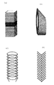
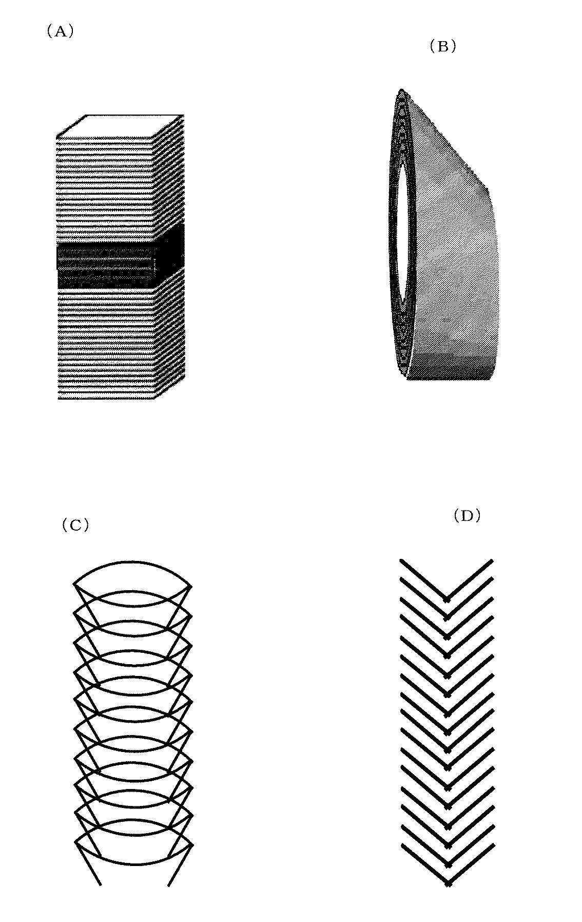
カーボンナノファイバー[CNF]について、図3(A)(B)(C)(D)に示すように、プレートタイプ[CNF-P]、チューブタイプ[CNF-T]、および、フィシュボーンタイプ(魚骨型)[CNF−F]が知られている。 About carbon nanofiber [CNF], as shown in Drawing 3 (A) (B) (C) (D), plate type [CNF-P], tube type [CNF-T], and fishbone type (fish Bone type) [CNF-F] is known.
図3(A)に示すように、プレートタイプのカーボンナノファイバー[CNF-P]は、平面状のグラファイト網がファイバーの縦軸に対して実質的に垂直に複数積層して形成された平均直径10〜500nmであって、アスペクト比が3以上のカーボンナノファイバーである。 As shown in FIG. 3A, the plate-type carbon nanofiber [CNF-P] has an average diameter formed by laminating a plurality of planar graphite nets substantially perpendicular to the longitudinal axis of the fiber. Carbon nanofibers having an aspect ratio of 3 or more and 10 to 500 nm.
図3(B)に示すように、チューブタイプのカーボンナノファイバー[CNF-T]は、複数のチューブ状のグラファイト網が同心円状に積層して形成された平均直径5〜100nmであって、アスペクト比が5以上のカーボンナノファイバーである。 As shown in FIG. 3B, the tube-type carbon nanofiber [CNF-T] has an average diameter of 5 to 100 nm formed by concentrically laminating a plurality of tube-shaped graphite nets, and has an aspect ratio. A carbon nanofiber having a ratio of 5 or more.
図3(C)、(D)に示すように、フィシュボーンタイプ(魚骨型)のカーボンナノファイバー[CNF−F]は、グラファイト網が、ファイバー軸に対して0°より大きくかつ90°より小さい範囲内の角度で複数積層し、かつファイバー軸の中心線で線対称とした様な形状で、平均直径は10〜500nmであって、アスペクト比が3以上のカーボンナノファイバーである。 As shown in FIGS. 3C and 3D, the fishbone type (fishbone type) carbon nanofiber [CNF-F] has a graphite net larger than 0 ° and 90 ° relative to the fiber axis. It is a carbon nanofiber having a shape in which a plurality of layers are laminated at an angle within a small range and the line is symmetrical with respect to the center line of the fiber axis, the average diameter is 10 to 500 nm, and the aspect ratio is 3 or more.
このフィシュボーンタイプ(魚骨型)のカーボンナノファイバー[CNF−F]には、図3(C)に示したような底の空いたカップ様のグラファイト網が複数積層した形状を有し、内部に大きな中空構造を持つもの、また図3(D)に示したような中空構造を持たないものなどがある。 This fishbone-type (fishbone-type) carbon nanofiber [CNF-F] has a shape in which multiple cup-like graphite nets with a bottom as shown in FIG. There are those having a large hollow structure, and those having no hollow structure as shown in FIG.
本発明の導電性樹脂組成物は、導電材として樹脂組成物に配合するカーボンナノファイバーについて、[CNF-P]と[CNF-T]の二種を併用し、または[CNF−F]と[CNF-T]の二種を併用し、または[CNF-P]と[CNF−F]と[CNF-T]の三種を併用し、これらを樹脂中に分散させて導電性を持たせた樹脂であり、表面抵抗について高い面内安定性(均一性)を有している。具体的には、表面抵抗の面内分布において、最も低い表面抵抗RLと最も高い表面抵抗RHの対数値の差(以下、表面抵抗の分布差と云う)が1以下〔[Log10RH−Log10RL]≦1〕である。 The conductive resin composition of the present invention is a combination of two types of [CNF-P] and [CNF-T] or [CNF-F] and [CNF-F] for carbon nanofibers blended in the resin composition as a conductive material. CNF-T] is used in combination, or [CNF-P], [CNF-F] and [CNF-T] are used in combination, and these are dispersed in the resin to provide conductivity. And has high in-plane stability (uniformity) in terms of surface resistance. Specifically, in the in-plane distribution of surface resistance, the difference between the logarithmic values of the lowest surface resistance RL and the highest surface resistance RH (hereinafter referred to as surface resistance distribution difference) is 1 or less [[Log10RH−Log10RL] ≦ 1].
カーボンナノファイバーについて、[CNF-P]と[CNF-T]、[CNF−F]と[CNF-T]、または[CNF-P]と[CNF−F]と[CNF-T]を併用せず、これらを個別に使用すると、表面抵抗の分布差を1以下にするのが難しい。例えば、比較例1、4に示すように、[CNF-P]と[CNF-T]を併用せずに[CNF-T]のみを用いた場合、表面抵抗の分布差は2.71(比較例1)、3.0(比較例4)であり、表面抵抗の分布差が大きい。 For carbon nanofibers, use [CNF-P] and [CNF-T], [CNF-F] and [CNF-T], or [CNF-P] and [CNF-F] and [CNF-T] in combination. If these are used individually, it is difficult to make the difference in surface resistance distribution 1 or less. For example, as shown in Comparative Examples 1 and 4, when only [CNF-T] is used without using [CNF-P] and [CNF-T], the difference in surface resistance distribution is 2.71 (comparison) Example 1) is 3.0 (Comparative Example 4), and the distribution difference of the surface resistance is large.
一方、[CNF-P]と[CNF-T]を併用し、または[CNF−F]と[CNF-T]を併用し、または[CNF-P]と[CNF−F]と[CNF-T]を併用すると、比較的高抵抗である[CNF-P]または[CNF−F]の導電パスが[CNF-T]によって結合されるので、全体にわたる接触条件の分布がなくなるため表面抵抗の分布差を1以下に制御することができる。 On the other hand, [CNF-P] and [CNF-T] are used together, or [CNF-F] and [CNF-T] are used together, or [CNF-P], [CNF-F] and [CNF-T] ] Together, the conductive path of [CNF-P] or [CNF-F], which has a relatively high resistance, is coupled by [CNF-T], so the distribution of surface resistance is eliminated because the distribution of contact conditions over the entire area is eliminated. The difference can be controlled to 1 or less.
[CNF-P]と[CNF-T]の混合割合は、[CNF-P]/[CNF-T]=50/50〜99.1/0.1の範囲が好ましい。また、[CNF−F]と[CNF-T]の混合割合は、[CNF−F]/[CNF-T]=50/50〜99.1/0.1の範囲が好ましい。また、[CNF-P]と[CNF−F]と[CNF-T]の混合割合は、([CNF-P]+[CNF−F])/[CNF-T]=50/50〜99.9/0.1の範囲が好ましい。 The mixing ratio of [CNF-P] and [CNF-T] is preferably in the range of [CNF-P] / [CNF-T] = 50/50 to 99.1 / 0.1. The mixing ratio of [CNF-F] and [CNF-T] is preferably in the range of [CNF-F] / [CNF-T] = 50/50 to 99.1 / 0.1. The mixing ratio of [CNF-P], [CNF-F] and [CNF-T] is ([CNF-P] + [CNF-F]) / [CNF-T] = 50/50 to 99. A range of 9 / 0.1 is preferred.
[CNF-P]の混合割合、あるいは[CNF−F]の混合割合、あるいは[CNF-P]と[CNF−F]の合計混合割合よりも[CNF-T]が多いと、[CNF−T]の導電性が支配的になり、[CNF-P]あるいは[CNF−F]の導電性を生かすことができない。一方、[CNF-T]の混合割合が0.1より少ないと、[CNF-P]、あるいは[CNF−F]、あるいは[CNF-P]と[CNF−F]と[CNF-T]を混合する効果が乏しくなるので好ましくない。 When [CNF-T] is higher than the mixing ratio of [CNF-P], or the mixing ratio of [CNF-F], or the total mixing ratio of [CNF-P] and [CNF-F], [CNF-T] The conductivity of [CNF-P] or [CNF-F] cannot be utilized. On the other hand, if the mixing ratio of [CNF-T] is less than 0.1, [CNF-P] or [CNF-F] or [CNF-P] and [CNF-F] and [CNF-T] This is not preferable because the mixing effect is poor.
樹脂中の[CNF-P]と[CNF-T]の合計含有量、樹脂中の[CNF−F]と[CNF-T]の合計含有量、樹脂中の[CNF-P]と[CNF−F]と[CNF-T]の合計含有量は、何れも0.5〜12質量%が好ましい。これらの含有量が0.5質量%より少ないと十分な導電性が得られず、12質量%よりも多くても導電性が頭打ちになる上、形成された樹脂フィルムの強度が劣化し始める。 Total content of [CNF-P] and [CNF-T] in the resin, total content of [CNF-F] and [CNF-T] in the resin, [CNF-P] and [CNF− in the resin The total content of [F] and [CNF-T] is preferably 0.5 to 12% by mass. When the content is less than 0.5% by mass, sufficient conductivity cannot be obtained. When the content is more than 12% by mass, the conductivity reaches a peak and the strength of the formed resin film starts to deteriorate.
本発明の導電性樹脂組成物は、高抵抗領域において平均表面抵抗が安定しており、例えば、CNF合計単位含有量(1質量%)あたりの平均表面抵抗の変化は対数値において1以下である。具体的には、カーボンナノファイバーの添加量がx質量%のときの平均表面抵抗がRx、カーボンナノファイバーの添加量が(x+1)質量%のときの平均表面抵抗がR(x+1)であるとき、平均表面抵抗の差が対数値において1以下〔[Log10Rx−Log10R(x+1)]≦1〕である。これは図1に示すように、表面抵抗Rが108Ω/□以上の高抵抗領域においても変わらない。一方、CNF-Tだけを使用した比較例5は108Ω/□以上の高抵抗領域において表面抵抗が急激に増加し、高抵抗領域の平均表面抵抗が不安定である。 The conductive resin composition of the present invention has a stable average surface resistance in a high resistance region. For example, a change in average surface resistance per CNF total unit content (1% by mass) is 1 or less in logarithmic value. . Specifically, when the average surface resistance is Rx when the amount of carbon nanofiber added is x mass%, and the average surface resistance is R (x + 1) when the amount of carbon nanofiber added is (x + 1) mass% The difference in average surface resistance is 1 or less [[Log10Rx−Log10R (x + 1)] ≦ 1] in the logarithmic value. As shown in FIG. 1, this does not change even in a high resistance region where the surface resistance R is 10 8 Ω / □ or more. On the other hand, in Comparative Example 5 using only CNF-T, the surface resistance rapidly increases in a high resistance region of 10 8 Ω / □ or more, and the average surface resistance in the high resistance region is unstable.
CNFを塗料や樹脂に分散させるには、CNF表面を酸化処理して分散性を高め、予めCNF分散液を調製し、これを塗料や樹脂に加えるとよい。また、表面処理したCNFを、塗料を構成する溶媒に分散させ、この分散液を塗料に混合するとよい。 In order to disperse CNF in a paint or resin, it is preferable to oxidize the CNF surface to increase dispersibility, prepare a CNF dispersion in advance, and add this to the paint or resin. Moreover, it is preferable to disperse the surface-treated CNF in a solvent constituting the paint and mix this dispersion with the paint.
本発明の導電性樹脂組成物は多様な形態で利用することができる。例えば、[CNF-P]と[CNF-T]の分散液、または[CNF−F]と[CNF-T]の分散液、または[CNF-P]と[CNF−F]と[CNF-T]の分散液を樹脂塗料中に分散混合させて導電性塗料を得ることができる。また、この塗料を機材に塗布、乾燥あるいは焼成して導電性機材を製造することができる。また、本発明の導電性樹脂組成物からなる導電性コンパウンド樹脂を原料とし、射出成形などの成形方法によって導電性に優れた樹脂成形物を容易に製造することができる。 The conductive resin composition of the present invention can be used in various forms. For example, a dispersion of [CNF-P] and [CNF-T], or a dispersion of [CNF-F] and [CNF-T], or [CNF-P], [CNF-F] and [CNF-T] Can be dispersed and mixed in a resin paint to obtain a conductive paint. In addition, this paint can be applied to the equipment, dried or fired to produce a conductive equipment. In addition, using a conductive compound resin made of the conductive resin composition of the present invention as a raw material, a resin molded product having excellent conductivity can be easily produced by a molding method such as injection molding.
以下、本発明の実施例を比較例と共に示す。各例において、表面抵抗はダイヤインスツルメンツ製のハイレスタ表面抵抗測定装置によって測定した。実施例1〜5、比較例1〜4の結果を表1に示した。実施例6〜11、比較例6〜8の結果を表2に示した。また、実施例1〜3および比較例5の結果を図1に示した。実施例6〜8および比較例5の結果を図2に示した。 Examples of the present invention are shown below together with comparative examples. In each example, the surface resistance was measured with a Hiresta surface resistance measuring device manufactured by Dia Instruments. The results of Examples 1 to 5 and Comparative Examples 1 to 4 are shown in Table 1. The results of Examples 6 to 11 and Comparative Examples 6 to 8 are shown in Table 2. The results of Examples 1 to 3 and Comparative Example 5 are shown in FIG. The results of Examples 6 to 8 and Comparative Example 5 are shown in FIG.
〔実施例1〕
[CNF-T]濃度を4質量%に調整したN-メチルピロリドン分散液、[CNF-P]濃度を4質量%に調整したN-メチルピロリドン分散液、市販のポリイミドワニス(固形分濃度18質量%)をそれぞれ準備し、ポリイミドワニスの固形分に対して、[CNF-T]を1.17質量%、[CNF-P]を5.7質量%になるように混合攪拌して均一な塗料を調製した。この塗料をバーコーターにてガラス基板上に塗布し、120℃に加熱して溶媒のNMPを蒸発させ、その後、350℃で熱処理し、[CNF-T]および[CNF-P]が分散したポリイミド塗膜(縦90mm×横270mm)を得た。この塗膜を縦3等分および横9等分に区切り(計27分割)、各区分の表面抵抗を測定した。平均表面抵抗は7.2×10¹⁰Ω/□であり、表面抵抗の分布差[Log10RH−Log10RL]は0.49であった。
[Example 1]
N-methylpyrrolidone dispersion with [CNF-T] concentration adjusted to 4% by mass, N-methylpyrrolidone dispersion with [CNF-P] concentration adjusted to 4% by mass, commercially available polyimide varnish (solid content concentration 18% by mass) %) And mix and stir so that [CNF-T] is 1.17 mass% and [CNF-P] is 5.7 mass% with respect to the solid content of the polyimide varnish. Was prepared. This paint is applied on a glass substrate with a bar coater, heated to 120 ° C. to evaporate NMP as a solvent, and then heat treated at 350 ° C. to obtain a polyimide in which [CNF-T] and [CNF-P] are dispersed. A coating film (90 mm long × 270 mm wide) was obtained. This coating was divided into 3 equal parts and 9 equal parts (total of 27 parts), and the surface resistance of each part was measured. The average surface resistance was 7.2 × 10 10 Ω / □, and the surface resistance distribution difference [Log10RH−Log10RL] was 0.49.
〔実施例2〕
[CNF−T]、[CNF−P]の分散液、およびポリイミドワニスを使用し、ポリイミドワニスの固形分に対して[CNF−T]を1.12質量%、[CNF−P]を7.6質量%になるように混合した以外は、実施例1と同様に塗膜を作成し、その表面抵抗を測定した。平均表面抵抗は2.4×10⁹Ω/□であり、表面抵抗の分布差は0.61であった。
[Example 2]
Using a dispersion of [CNF-T] and [CNF-P] and a polyimide varnish, 1.12% by mass of [CNF-T] and 7.7 [CNF-P] based on the solid content of the polyimide varnish. A coating film was prepared in the same manner as in Example 1 except that mixing was performed so that the amount was 6% by mass, and the surface resistance was measured. The average surface resistance was 2.4 × 10 9 Ω / □, and the difference in surface resistance distribution was 0.61.
〔実施例3〕
[CNF−T]、[CNF−P]の分散液、およびポリイミドワニスを使用し、ポリイミドワニスの固形分に対して[CNF−T]を1.17質量%、[CNF−P]を4.6質量%になるように混合した以外は、実施例1と同様に塗膜を作成し、その表面抵抗を測定した。平均表面抵抗は3.1×10¹¹Ω/□であり、表面抵抗の分布差は0.73であった。
Example 3
[CNF-T], [CNF-P] dispersion, and polyimide varnish were used. [CNF-T] was 1.17% by mass and [CNF-P] was 4. A coating film was prepared in the same manner as in Example 1 except that mixing was performed so that the amount was 6% by mass, and the surface resistance was measured. The average surface resistance was 3.1 × 10 11 Ω / □, and the difference in surface resistance distribution was 0.73.
〔実施例4〕
ポリカーボネイト樹脂に、[CNF−T]と[CNF−P]をそれぞれ2質量%、4質量%含有するように添加して混錬し、コンパウンドを製造した。このコンパウンドを熱プレスにて厚さ40μmのシート、半径15cmの円盤状のシートをおのおの作成し、面内の表面抵抗を10箇所測定した。平均表面抵抗は3.4×10⁹Ω/□であり、表面抵抗の分布差は0.54であった。
Example 4
A compound was produced by adding and kneading [CNF-T] and [CNF-P] to the polycarbonate resin so as to contain 2% by mass and 4% by mass, respectively. Each of the compounds was prepared by hot pressing to form a sheet having a thickness of 40 μm and a disk-shaped sheet having a radius of 15 cm, and the in-plane surface resistance was measured at 10 points. The average surface resistance was 3.4 × 10 9 Ω / □, and the difference in surface resistance distribution was 0.54.
〔実施例5〕
樹脂をポリカーボネイトからペット樹脂に変更した以外は実施例4と同様の組成のコンパウンドを作成し、熱プレスシートを作成してその表面抵抗を測定した。平均表面抵抗は8×10⁸Ω/□であり、表面抵抗の分布差は0.26であった。
Example 5
A compound having the same composition as in Example 4 was prepared except that the resin was changed from polycarbonate to pet resin, a hot press sheet was prepared, and the surface resistance was measured. The average surface resistance was 8 × 10 8 Ω / □, and the difference in surface resistance distribution was 0.26.
〔比較例1〕
[CNF−T]分散液およびポリイミドワニスを使用し、ポリイミドワニスの固形分に対して[CNF−T]を1.1質量%になるように混合した([CNF−P]は併用せず)。それ以外は実施例1と同様に塗膜を作成し、その表面抵抗を測定した。平均表面抵抗は2.5×10¹¹Ω/□であり、表面抵抗の分布差は2.71であった。
[Comparative Example 1]
Using [CNF-T] dispersion and polyimide varnish, [CNF-T] was mixed to 1.1% by mass with respect to the solid content of the polyimide varnish ([CNF-P] was not used together) . Otherwise, a coating film was prepared in the same manner as in Example 1, and the surface resistance was measured. The average surface resistance was 2.5 × 10 11 Ω / □, and the difference in surface resistance distribution was 2.71.
〔比較例2〕
[CNF−T]に代えて[CNF−P]を用い、[CNF−P]の添加量を13質量%とした以外は実施例1と同様に塗膜を作成し、その表面抵抗を測定した。平均表面抵抗は1.2×10¹¹Ω/□であり、表面抵抗の分布差は2.26であった。
[Comparative Example 2]
A coating film was prepared in the same manner as in Example 1 except that [CNF-P] was used instead of [CNF-T], and the addition amount of [CNF-P] was 13% by mass, and the surface resistance was measured. . The average surface resistance was 1.2 × 10 11 Ω / □, and the difference in surface resistance distribution was 2.26.
〔比較例3〕
[CNF−T]、[CNF−P]の分散液、およびポリイミドワニスを使用し、ポリイミドワニスの固形分に対して[CNF−T]を0.2質量%、[CNF−P]を0.2質量%になるように混合した以外は、実施例1と同様に塗膜を作成し、その表面抵抗を測定した。平均表面抵抗は1.0×10¹³Ω/□以上であった。
[Comparative Example 3]
Using a dispersion of [CNF-T] and [CNF-P] and a polyimide varnish, 0.2% by mass of [CNF-T] and [CNF-P] of 0.2% with respect to the solid content of the polyimide varnish. A coating film was prepared in the same manner as in Example 1 except that the amount was 2% by mass, and the surface resistance was measured. The average surface resistance was 1.0 × 10 13 Ω / □ or more.
〔比較例4〕
ポリカーボネイト樹脂に[CNF−T]だけを2質量%になるように添加して混錬した以外は実施例4と同様にして熱プレスシート(厚さ40μm)を作成し、面内の表面抵抗を10箇所測定した。平均表面抵抗は1×10⁷Ω/□であり、表面抵抗の分布差は3.0であった。
[Comparative Example 4]
A hot press sheet (thickness 40 μm) was prepared in the same manner as in Example 4 except that only [CNF-T] was added to the polycarbonate resin so as to be 2% by mass and kneaded, and the in-plane surface resistance was reduced. Ten locations were measured. The average surface resistance was 1 × 10 7 Ω / □, and the difference in surface resistance distribution was 3.0.
〔比較例5〕
[CNF−T]だけを使用し、その使用量をおのおの1.0質量%、1.1質量%、1.4質量%、1.6質量%、3質量%、5質量%、10質量%とした以外は実施例1と同様に塗膜を作成し、その表面抵抗を測定した。その結果を図1および図2の▲でプロットした。このデータより明らかなように、[CNF−T]だけを使用して高抵抗値のコントロールを行おうとした場合には、CNF添加量が2質量%以下の高抵抗領域において、表面抵抗の急激な変化が見られ、高抵抗値のコントロールは困難になる。
[Comparative Example 5]
Only [CNF-T] is used, and the amount used is 1.0 mass%, 1.1 mass%, 1.4 mass%, 1.6 mass%, 3 mass%, 5 mass%, 10 mass%, respectively. A coating film was prepared in the same manner as in Example 1 except that the surface resistance was measured. The results were plotted with ▲ in FIG. 1 and FIG. As is clear from this data, when controlling high resistance value using only [CNF-T], in the high resistance region where CNF addition amount is 2 mass% or less, the surface resistance is abrupt. Changes are seen, making it difficult to control high resistance values.
表1の比較例1および比較例2に示すように、[CNF−T]あるいは[CNF−P]だけを使用して高抵抗領域の表面抵抗をコントロールしようとした場合には、表面抵抗の分布差が大きくなり、抵抗値の安定した塗膜の作成はできなかった。また、[CNF−T]と[CNF−P]の合計量が0.4の比較例3は表面抵抗が大幅に高くなり、そのコントロールは不可能であった。同様に、比較例4は樹脂を変えて[CNF−T]だけを用いた例であり、比較例1〜2と同様に、単一組成の導電材であるため表面抵抗分布差が大きい。 As shown in Comparative Example 1 and Comparative Example 2 in Table 1, when the surface resistance of the high resistance region is controlled using only [CNF-T] or [CNF-P], the distribution of the surface resistance The difference became large, and it was impossible to produce a coating film having a stable resistance value. Further, in Comparative Example 3 in which the total amount of [CNF-T] and [CNF-P] was 0.4, the surface resistance was significantly increased, and the control thereof was impossible. Similarly, Comparative Example 4 is an example in which only [CNF-T] is used by changing the resin. Like Comparative Examples 1 and 2, since the conductive material has a single composition, the difference in surface resistance distribution is large.
一方、図1に示すように、実施例1〜実施例3では、高抵抗領域(109〜1013Ω/□)において表面抵抗の変化は一定であり、急激に変化する現象は見られない。具体的には、図1に示すように、CNF合計単位含有量(1質量%)あたりの平均表面抵抗Rの変化は表面抵抗を示す対数グラフにおいて一桁以下である。従って、表面抵抗の制御が容易である。 On the other hand, as shown in FIG. 1, in Examples 1 to 3, the change in surface resistance is constant in the high resistance region (10 9 to 10 13 Ω / □), and a phenomenon of rapid change is not observed. . Specifically, as shown in FIG. 1, the change of the average surface resistance R per CNF total unit content (1 mass%) is one digit or less in the logarithmic graph showing the surface resistance. Therefore, it is easy to control the surface resistance.
〔実施例6〕
[CNF−T]濃度を4質量%に調整したN-メチルピロリドン分散液、[CNF−F]濃度を4質量%に調整したN-メチルピロリドン分散液、市販のポリイミドワニス(固形分濃度18質量%)をそれぞれ準備し、ポリイミドワニスの固形分に対して、[CNF−T]を0.75質量%、[CNF−F]を10質量%になるように混合攪拌して均一な塗料を調製した。この塗料をバーコーターにてガラス基板上に塗布し、120℃に加熱して溶媒のNMPを蒸発させ、その後、350℃で熱処理し、[CNF−T]および[CNF−F]が分散したポリイミド塗膜(縦90mm×横270mm)を得た。この塗膜を縦3等分および横9等分に区切り(計27分割)、各区分の表面抵抗を測定した。平均表面抵抗は1.9×10¹⁰Ω/□であり、表面抵抗の分布差[Log10RH−Log10RL]は0.52であった。
Example 6
[CNF-T] N-methylpyrrolidone dispersion adjusted to 4 mass%, [CNF-F] N-methylpyrrolidone dispersion adjusted to 4 mass%, commercially available polyimide varnish (solid content concentration 18 mass %) Are prepared and mixed with stirring so that [CNF-T] is 0.75 mass% and [CNF-F] is 10 mass% with respect to the solid content of the polyimide varnish. did. This paint is applied on a glass substrate with a bar coater, heated to 120 ° C. to evaporate NMP as a solvent, and then heat-treated at 350 ° C. to obtain a polyimide in which [CNF-T] and [CNF-F] are dispersed. A coating film (90 mm long × 270 mm wide) was obtained. This coating was divided into 3 equal parts and 9 equal parts (total of 27 parts), and the surface resistance of each part was measured. The average surface resistance was 1.9 × 10 10 Ω / □, and the surface resistance distribution difference [Log10RH−Log10RL] was 0.52.
〔実施例7〕
[CNF−T]、[CNF−F]の分散液、およびポリイミドワニスを使用し、ポリイミドワニスの固形分に対して[CNF−T]を0.75質量%、[CNF−F]を7.5質量%になるように混合した以外は、実施例6と同様に塗膜を作成し、その表面抵抗を測定した。平均表面抵抗は5.2×10¹¹Ω/□であり、表面抵抗の分布差は0.63であった。
Example 7
[CNF-T], [CNF-F] dispersion, and polyimide varnish were used. [CNF-T] was 0.75% by mass and [CNF-F] was 7. A coating film was prepared in the same manner as in Example 6 except that the amount was 5% by mass, and the surface resistance was measured. The average surface resistance was 5.2 × 10 11 Ω / □, and the difference in surface resistance distribution was 0.63.
〔実施例8〕
[CNF−T]、[CNF−F]の分散液、およびポリイミドワニスを使用し、ポリイミドワニスの固形分に対して[CNF−T]を0.75質量%、[CNF−F]を5質量%になるように混合した以外は、実施例6と同様に塗膜を作成し、その表面抵抗を測定した。平均表面抵抗は8.0×10¹²Ω/□であり、表面抵抗の分布差は0.71であった。
Example 8
Using [CNF-T], [CNF-F] dispersion and polyimide varnish, 0.75 mass% of [CNF-T] and 5 mass of [CNF-F] based on the solid content of the polyimide varnish A coating film was prepared in the same manner as in Example 6 except that mixing was performed so as to be%, and the surface resistance was measured. The average surface resistance was 8.0 × 10 12 Ω / □, and the difference in surface resistance distribution was 0.71.
〔実施例9〕
ポリカーボネイト樹脂に、[CNF−T]と[CNF−F]をそれぞれ2質量%、4質量%含有するように添加して混錬し、コンパウンドを製造した。このコンパウンドを熱プレスにて厚さ40μmのシート、半径15cmの円盤状のシートをおのおの作成し、面内の表面抵抗を10箇所測定した。平均表面抵抗は1.2×10¹⁰Ω/□であり、表面抵抗の分布差は0.57であった。
Example 9
A compound was produced by adding and kneading [CNF-T] and [CNF-F] to the polycarbonate resin so as to contain 2% by mass and 4% by mass, respectively. Each of the compounds was prepared by hot pressing to form a sheet having a thickness of 40 μm and a disk-shaped sheet having a radius of 15 cm, and the in-plane surface resistance was measured at 10 points. The average surface resistance was 1.2 × 10 10 Ω / □, and the surface resistance distribution difference was 0.57.
〔実施例10〕
樹脂をポリカーボネイトからペット樹脂に変更した以外は実施例9と同様の組成のコンパウンドを作成し、熱プレスシートを作成してその表面抵抗を測定した。平均表面抵抗は3.3×10⁹Ω/□であり、表面抵抗の分布差は0.34であった。
Example 10
A compound having the same composition as in Example 9 was prepared except that the resin was changed from polycarbonate to pet resin, a hot press sheet was prepared, and the surface resistance was measured. The average surface resistance was 3.3 × 10 9 Ω / □, and the difference in surface resistance distribution was 0.34.
〔実施例11〕
[CNF−T]濃度を4質量%に調整したN-メチルピロリドン分散液、[CNF−P]濃度を4質量%に調整したN-メチルピロリドン分散液、[CNF−F]濃度を4質量%に調整したN-メチルピロリドン分散液、市販のポリイミドワニス(固形分濃度18質量%)をそれぞれ準備し、ポリイミドワニスの固形分に対して、[CNF−T]を0.75質量%、[CNF−P]を4.0質量%、[CNF−F]を4.0質量%になるように混合攪拌して均一な塗料を調製した。この塗料をバーコーターにてガラス基板上に塗布し、120℃に加熱して溶媒のNMPを蒸発させ、その後、350℃で熱処理し、[CNF−T]、[CNF−P]、[CNF−F]が分散したポリイミド塗膜(縦90mm×横270mm)を得た。この塗膜を縦3等分および横9等分に区切り(計27分割)、各区分の表面抵抗を測定した。平均表面抵抗は1.3×10¹¹Ω/□であり、表面抵抗の分布差[Log10RH−Log10RL]は0.60であった。
Example 11
N-methylpyrrolidone dispersion with [CNF-T] concentration adjusted to 4% by mass, N-methylpyrrolidone dispersion with [CNF-P] concentration adjusted to 4% by mass, and [CNF-F]
〔比較例6〕
[CNF−T]分散液およびポリイミドワニスを使用し、ポリイミドワニスの固形分に対して[CNF−T]を1.1質量%になるように混合した([CNF−F]は併用せず)。それ以外は実施例6と同様に塗膜を作成し、その表面抵抗を測定した。平均表面抵抗は2.5×10¹¹Ω/□であり、表面抵抗の分布差は2.71であった。
[Comparative Example 6]
Using [CNF-T] dispersion and polyimide varnish, [CNF-T] was mixed to 1.1% by mass with respect to the solid content of the polyimide varnish ([CNF-F] was not used together) . Otherwise, a coating film was prepared in the same manner as in Example 6, and the surface resistance was measured. The average surface resistance was 2.5 × 10 11 Ω / □, and the difference in surface resistance distribution was 2.71.
〔比較例7〕
[CNF−T]に代えて[CNF−F]を用い、[CNF−F]の添加量を13質量%とした以外は実施例6と同様に塗膜を作成し、その表面抵抗を測定した。平均表面抵抗は8.9×10¹¹Ω/□であり、表面抵抗の分布差は2.54であった。
[Comparative Example 7]
A coating film was prepared in the same manner as in Example 6 except that [CNF-F] was used instead of [CNF-T], and the addition amount of [CNF-F] was 13% by mass, and the surface resistance was measured. . The average surface resistance was 8.9 × 10 11 Ω / □, and the difference in surface resistance distribution was 2.54.
〔比較例8〕
[CNF−T]、[CNF−F]の分散液、およびポリイミドワニスを使用し、ポリイミドワニスの固形分に対して[CNF−T]を0.2質量%、[CNF−F]を0.2質量%になるように混合した以外は、実施例6と同様に塗膜を作成し、その表面抵抗を測定した。平均表面抵抗は1.0×10¹³Ω/□以上であった。
[Comparative Example 8]
Using a dispersion of [CNF-T] and [CNF-F] and a polyimide varnish, 0.2% by mass of [CNF-T] and 0.2% of [CNF-F] based on the solid content of the polyimide varnish. A coating film was prepared in the same manner as in Example 6 except that mixing was performed so that the amount was 2% by mass, and the surface resistance was measured. The average surface resistance was 1.0 × 10 13 Ω / □ or more.
表2の比較例6および比較例7に示すように、[CNF−T]あるいは[CNF−F]だけを使用して高抵抗領域の表面抵抗をコントロールしようとした場合には、表面抵抗の分布差が大きくなり、抵抗値の安定した塗膜の作成はできなかった。また、[CNF−T]と[CNF−F]の合計量が0.4の比較例8は表面抵抗が大幅に高くなり、そのコントロールは不可能であった。 As shown in Comparative Example 6 and Comparative Example 7 in Table 2, when the surface resistance of the high resistance region is controlled using only [CNF-T] or [CNF-F], the distribution of the surface resistance The difference became large, and it was impossible to produce a coating film having a stable resistance value. Further, in Comparative Example 8 in which the total amount of [CNF-T] and [CNF-F] was 0.4, the surface resistance was significantly increased, and the control thereof was impossible.
一方、図2に示すように、実施例6〜実施例8では、高抵抗領域(109〜1013Ω/□)において表面抵抗の変化は一定であり、急激に変化する現象は見られない。具体的には、図2に示すように、CNF合計単位含有量(1質量%)あたりの平均表面抵抗Rの変化は表面抵抗を示す対数グラフにおいて一桁以下である。従って、表面抵抗の制御が容易である。 On the other hand, as shown in FIG. 2, in Examples 6 to 8, the change in surface resistance is constant in the high resistance region (10 9 to 10 13 Ω / □), and a phenomenon of rapid change is not observed. . Specifically, as shown in FIG. 2, the change of the average surface resistance R per CNF total unit content (1 mass%) is one digit or less in the logarithmic graph showing the surface resistance. Therefore, it is easy to control the surface resistance.
Claims (11)
Priority Applications (1)
| Application Number | Priority Date | Filing Date | Title |
|---|---|---|---|
| JP2009047034A JP5514452B2 (en) | 2008-05-28 | 2009-02-27 | Conductive resin composition and molded body thereof |
Applications Claiming Priority (3)
| Application Number | Priority Date | Filing Date | Title |
|---|---|---|---|
| JP2008139909 | 2008-05-28 | ||
| JP2008139909 | 2008-05-28 | ||
| JP2009047034A JP5514452B2 (en) | 2008-05-28 | 2009-02-27 | Conductive resin composition and molded body thereof |
Publications (2)
| Publication Number | Publication Date |
|---|---|
| JP2010007046A true JP2010007046A (en) | 2010-01-14 |
| JP5514452B2 JP5514452B2 (en) | 2014-06-04 |
Family
ID=41587886
Family Applications (1)
| Application Number | Title | Priority Date | Filing Date |
|---|---|---|---|
| JP2009047034A Active JP5514452B2 (en) | 2008-05-28 | 2009-02-27 | Conductive resin composition and molded body thereof |
Country Status (1)
| Country | Link |
|---|---|
| JP (1) | JP5514452B2 (en) |
Cited By (1)
| Publication number | Priority date | Publication date | Assignee | Title |
|---|---|---|---|---|
| JP2012167186A (en) * | 2011-02-14 | 2012-09-06 | Osaka Prefecture | Nanocarbon dispersion polyimide solution, and composite material manufactured by using the same |
Citations (5)
| Publication number | Priority date | Publication date | Assignee | Title |
|---|---|---|---|---|
| JP2006152132A (en) * | 2004-11-30 | 2006-06-15 | Mitsubishi Materials Corp | Electroconductive resin sheet |
| JP2007231089A (en) * | 2006-02-28 | 2007-09-13 | Mitsubishi Materials Corp | Electroconductive composition and its molded body |
| JP2008019538A (en) * | 2006-07-14 | 2008-01-31 | Sonac Kk | Constituting unit of carbon nanofiber, and the carbon nanofiber |
| JP2008511741A (en) * | 2004-08-31 | 2008-04-17 | ハイピリオン カタリシス インターナショナル インコーポレイテッド | Conductive thermosetting resin by extrusion |
| JP2008138039A (en) * | 2006-11-30 | 2008-06-19 | Mitsubishi Materials Corp | Carbon nanofiber-dispersed polyimide varnish and coating film thereof |
-
2009
- 2009-02-27 JP JP2009047034A patent/JP5514452B2/en active Active
Patent Citations (5)
| Publication number | Priority date | Publication date | Assignee | Title |
|---|---|---|---|---|
| JP2008511741A (en) * | 2004-08-31 | 2008-04-17 | ハイピリオン カタリシス インターナショナル インコーポレイテッド | Conductive thermosetting resin by extrusion |
| JP2006152132A (en) * | 2004-11-30 | 2006-06-15 | Mitsubishi Materials Corp | Electroconductive resin sheet |
| JP2007231089A (en) * | 2006-02-28 | 2007-09-13 | Mitsubishi Materials Corp | Electroconductive composition and its molded body |
| JP2008019538A (en) * | 2006-07-14 | 2008-01-31 | Sonac Kk | Constituting unit of carbon nanofiber, and the carbon nanofiber |
| JP2008138039A (en) * | 2006-11-30 | 2008-06-19 | Mitsubishi Materials Corp | Carbon nanofiber-dispersed polyimide varnish and coating film thereof |
Cited By (1)
| Publication number | Priority date | Publication date | Assignee | Title |
|---|---|---|---|---|
| JP2012167186A (en) * | 2011-02-14 | 2012-09-06 | Osaka Prefecture | Nanocarbon dispersion polyimide solution, and composite material manufactured by using the same |
Also Published As
| Publication number | Publication date |
|---|---|
| JP5514452B2 (en) | 2014-06-04 |
Similar Documents
| Publication | Publication Date | Title |
|---|---|---|
| DE69817887T2 (en) | Intermediate transfer members | |
| DE69820174T2 (en) | Polyimide components for the transfer of toner images | |
| JP5131426B2 (en) | Carbon nanofiber dispersed polyimide varnish and coating film thereof | |
| US6352750B1 (en) | Seamless tubular electrically-semiconductive aromatic polymide film and process for producing the same | |
| DE102011006324B4 (en) | Intermediate transfer member and image forming apparatus | |
| US20120207525A1 (en) | Resistance heating composition and heating composite, heating apparatus, and fusing apparatus, including resistance heating composition | |
| JPS6239678A (en) | Polymer thick film ink and its use | |
| JP2003246927A (en) | Polyimide resin composition, polyimide film, polyimide tubular article and electrophotographic tubular article | |
| JP2007231089A (en) | Electroconductive composition and its molded body | |
| KR20150095406A (en) | Printable high heat resistance heating paste composition | |
| JP5514452B2 (en) | Conductive resin composition and molded body thereof | |
| JP2013077427A (en) | Conductive particle and its use | |
| DE102011087563A1 (en) | Method and apparatus for renewing an intermediate transfer element | |
| WO2002022740A1 (en) | Polyimide resin composition and, polyimide product formed into film and intermediate transfer belt comprising the same | |
| JP2002088242A (en) | Polyimide resin composition and polyimide film-like molded body | |
| DE102014217813B4 (en) | intermediate transfer elements | |
| JP2007224207A (en) | Electroconductive composition, electroconductive coating material, electroconductive fiber material, method for producing electroconductive fiber material, and flat heater | |
| US9274469B2 (en) | Composition for making flow-coatable fuser topcoat and method of making a fuser topcoat | |
| JP2006272839A (en) | Seamless belt and its manufacturing method | |
| JP5866210B2 (en) | Endless flexible member for an imaging device | |
| JP2003306553A (en) | Molded polyimide article | |
| JP2007077551A (en) | Conductive fiber, raised fabric for conductive brush, conductive brush | |
| JP2003055473A (en) | Polyimide tubular product and tubular product for electrophotography | |
| JP2004207097A (en) | Conductive resin composition | |
| WO2013191440A1 (en) | Seamless belt |
Legal Events
| Date | Code | Title | Description |
|---|---|---|---|
| A621 | Written request for application examination |
Free format text: JAPANESE INTERMEDIATE CODE: A621 Effective date: 20120223 |
|
| A977 | Report on retrieval |
Free format text: JAPANESE INTERMEDIATE CODE: A971007 Effective date: 20130626 |
|
| A131 | Notification of reasons for refusal |
Free format text: JAPANESE INTERMEDIATE CODE: A131 Effective date: 20130710 |
|
| A521 | Request for written amendment filed |
Free format text: JAPANESE INTERMEDIATE CODE: A523 Effective date: 20130906 |
|
| A131 | Notification of reasons for refusal |
Free format text: JAPANESE INTERMEDIATE CODE: A131 Effective date: 20131204 |
|
| A521 | Request for written amendment filed |
Free format text: JAPANESE INTERMEDIATE CODE: A523 Effective date: 20140130 |
|
| TRDD | Decision of grant or rejection written | ||
| A01 | Written decision to grant a patent or to grant a registration (utility model) |
Free format text: JAPANESE INTERMEDIATE CODE: A01 Effective date: 20140305 |
|
| A61 | First payment of annual fees (during grant procedure) |
Free format text: JAPANESE INTERMEDIATE CODE: A61 Effective date: 20140331 |
|
| R150 | Certificate of patent or registration of utility model |
Ref document number: 5514452 Country of ref document: JP Free format text: JAPANESE INTERMEDIATE CODE: R150 |
|
| R250 | Receipt of annual fees |
Free format text: JAPANESE INTERMEDIATE CODE: R250 |
|
| R250 | Receipt of annual fees |
Free format text: JAPANESE INTERMEDIATE CODE: R250 |
|
| R250 | Receipt of annual fees |
Free format text: JAPANESE INTERMEDIATE CODE: R250 |
|
| R250 | Receipt of annual fees |
Free format text: JAPANESE INTERMEDIATE CODE: R250 |
|
| R250 | Receipt of annual fees |
Free format text: JAPANESE INTERMEDIATE CODE: R250 |
|
| R250 | Receipt of annual fees |
Free format text: JAPANESE INTERMEDIATE CODE: R250 |
|
| R250 | Receipt of annual fees |
Free format text: JAPANESE INTERMEDIATE CODE: R250 |