JP2009541015A - Ultrasonic wound treatment apparatus and method - Google Patents
Ultrasonic wound treatment apparatus and method Download PDFInfo
- Publication number
- JP2009541015A JP2009541015A JP2009518440A JP2009518440A JP2009541015A JP 2009541015 A JP2009541015 A JP 2009541015A JP 2009518440 A JP2009518440 A JP 2009518440A JP 2009518440 A JP2009518440 A JP 2009518440A JP 2009541015 A JP2009541015 A JP 2009541015A
- Authority
- JP
- Japan
- Prior art keywords
- instrument
- chamber
- cavitation
- contact medium
- cavitation chamber
- Prior art date
- Legal status (The legal status is an assumption and is not a legal conclusion. Google has not performed a legal analysis and makes no representation as to the accuracy of the status listed.)
- Pending
Links
- 0 C[C@](**)(CC1C2)C(C3)C1C2*3O Chemical compound C[C@](**)(CC1C2)C(C3)C1C2*3O 0.000 description 1
Images


Classifications
-
- A—HUMAN NECESSITIES
- A61—MEDICAL OR VETERINARY SCIENCE; HYGIENE
- A61N—ELECTROTHERAPY; MAGNETOTHERAPY; RADIATION THERAPY; ULTRASOUND THERAPY
- A61N7/00—Ultrasound therapy
-
- A—HUMAN NECESSITIES
- A61—MEDICAL OR VETERINARY SCIENCE; HYGIENE
- A61B—DIAGNOSIS; SURGERY; IDENTIFICATION
- A61B18/00—Surgical instruments, devices or methods for transferring non-mechanical forms of energy to or from the body
-
- A—HUMAN NECESSITIES
- A61—MEDICAL OR VETERINARY SCIENCE; HYGIENE
- A61H—PHYSICAL THERAPY APPARATUS, e.g. DEVICES FOR LOCATING OR STIMULATING REFLEX POINTS IN THE BODY; ARTIFICIAL RESPIRATION; MASSAGE; BATHING DEVICES FOR SPECIAL THERAPEUTIC OR HYGIENIC PURPOSES OR SPECIFIC PARTS OF THE BODY
- A61H1/00—Apparatus for passive exercising; Vibrating apparatus ; Chiropractic devices, e.g. body impacting devices, external devices for briefly extending or aligning unbroken bones
-
- A—HUMAN NECESSITIES
- A61—MEDICAL OR VETERINARY SCIENCE; HYGIENE
- A61H—PHYSICAL THERAPY APPARATUS, e.g. DEVICES FOR LOCATING OR STIMULATING REFLEX POINTS IN THE BODY; ARTIFICIAL RESPIRATION; MASSAGE; BATHING DEVICES FOR SPECIAL THERAPEUTIC OR HYGIENIC PURPOSES OR SPECIFIC PARTS OF THE BODY
- A61H23/00—Percussion or vibration massage, e.g. using supersonic vibration; Suction-vibration massage; Massage with moving diaphragms
-
- A—HUMAN NECESSITIES
- A61—MEDICAL OR VETERINARY SCIENCE; HYGIENE
- A61M—DEVICES FOR INTRODUCING MEDIA INTO, OR ONTO, THE BODY; DEVICES FOR TRANSDUCING BODY MEDIA OR FOR TAKING MEDIA FROM THE BODY; DEVICES FOR PRODUCING OR ENDING SLEEP OR STUPOR
- A61M1/00—Suction or pumping devices for medical purposes; Devices for carrying-off, for treatment of, or for carrying-over, body-liquids; Drainage systems
- A61M1/90—Negative pressure wound therapy devices, i.e. devices for applying suction to a wound to promote healing, e.g. including a vacuum dressing
- A61M1/92—Negative pressure wound therapy devices, i.e. devices for applying suction to a wound to promote healing, e.g. including a vacuum dressing with liquid supply means
-
- A—HUMAN NECESSITIES
- A61—MEDICAL OR VETERINARY SCIENCE; HYGIENE
- A61B—DIAGNOSIS; SURGERY; IDENTIFICATION
- A61B17/00—Surgical instruments, devices or methods, e.g. tourniquets
- A61B17/22—Implements for squeezing-off ulcers or the like on the inside of inner organs of the body; Implements for scraping-out cavities of body organs, e.g. bones; Calculus removers; Calculus smashing apparatus; Apparatus for removing obstructions in blood vessels, not otherwise provided for
- A61B17/22004—Implements for squeezing-off ulcers or the like on the inside of inner organs of the body; Implements for scraping-out cavities of body organs, e.g. bones; Calculus removers; Calculus smashing apparatus; Apparatus for removing obstructions in blood vessels, not otherwise provided for using mechanical vibrations, e.g. ultrasonic shock waves
- A61B2017/22005—Effects, e.g. on tissue
- A61B2017/22007—Cavitation or pseudocavitation, i.e. creation of gas bubbles generating a secondary shock wave when collapsing
- A61B2017/22008—Cavitation or pseudocavitation, i.e. creation of gas bubbles generating a secondary shock wave when collapsing used or promoted
-
- A—HUMAN NECESSITIES
- A61—MEDICAL OR VETERINARY SCIENCE; HYGIENE
- A61B—DIAGNOSIS; SURGERY; IDENTIFICATION
- A61B17/00—Surgical instruments, devices or methods, e.g. tourniquets
- A61B17/22—Implements for squeezing-off ulcers or the like on the inside of inner organs of the body; Implements for scraping-out cavities of body organs, e.g. bones; Calculus removers; Calculus smashing apparatus; Apparatus for removing obstructions in blood vessels, not otherwise provided for
- A61B17/225—Implements for squeezing-off ulcers or the like on the inside of inner organs of the body; Implements for scraping-out cavities of body organs, e.g. bones; Calculus removers; Calculus smashing apparatus; Apparatus for removing obstructions in blood vessels, not otherwise provided for for extracorporeal shock wave lithotripsy [ESWL], e.g. by using ultrasonic waves
- A61B17/2251—Implements for squeezing-off ulcers or the like on the inside of inner organs of the body; Implements for scraping-out cavities of body organs, e.g. bones; Calculus removers; Calculus smashing apparatus; Apparatus for removing obstructions in blood vessels, not otherwise provided for for extracorporeal shock wave lithotripsy [ESWL], e.g. by using ultrasonic waves characterised by coupling elements between the apparatus, e.g. shock wave apparatus or locating means, and the patient, e.g. details of bags, pressure control of bag on patient
- A61B2017/2253—Implements for squeezing-off ulcers or the like on the inside of inner organs of the body; Implements for scraping-out cavities of body organs, e.g. bones; Calculus removers; Calculus smashing apparatus; Apparatus for removing obstructions in blood vessels, not otherwise provided for for extracorporeal shock wave lithotripsy [ESWL], e.g. by using ultrasonic waves characterised by coupling elements between the apparatus, e.g. shock wave apparatus or locating means, and the patient, e.g. details of bags, pressure control of bag on patient using a coupling gel or liquid
-
- A—HUMAN NECESSITIES
- A61—MEDICAL OR VETERINARY SCIENCE; HYGIENE
- A61M—DEVICES FOR INTRODUCING MEDIA INTO, OR ONTO, THE BODY; DEVICES FOR TRANSDUCING BODY MEDIA OR FOR TAKING MEDIA FROM THE BODY; DEVICES FOR PRODUCING OR ENDING SLEEP OR STUPOR
- A61M1/00—Suction or pumping devices for medical purposes; Devices for carrying-off, for treatment of, or for carrying-over, body-liquids; Drainage systems
- A61M1/90—Negative pressure wound therapy devices, i.e. devices for applying suction to a wound to promote healing, e.g. including a vacuum dressing
- A61M1/96—Suction control thereof
- A61M1/962—Suction control thereof having pumping means on the suction site, e.g. miniature pump on dressing or dressing capable of exerting suction
-
- A—HUMAN NECESSITIES
- A61—MEDICAL OR VETERINARY SCIENCE; HYGIENE
- A61N—ELECTROTHERAPY; MAGNETOTHERAPY; RADIATION THERAPY; ULTRASOUND THERAPY
- A61N7/00—Ultrasound therapy
- A61N2007/0039—Ultrasound therapy using microbubbles
Abstract
本発明は、傷を治療するための超音波器具及び方法に関する。超音波による傷の治療器具は、発生器と、超音波トランスデューサと、キャビテーションチャンバと、を具えている。さらに、本器具は、アトマイズ処理していない流体の接触媒体を具えている。キャビテーションチャンバに入る超音波は、接触媒体の中でキャビテーションを誘起し、治療される傷に対する治療上の利点を与える。また、キャビテーションチャンバに入る超音波は、接触媒体を通って傷に伝送され、傷に対する直接的な治療上の利点を与える。
【選択図】図1The present invention relates to an ultrasonic instrument and method for treating wounds. An ultrasonic wound treatment instrument includes a generator, an ultrasonic transducer, and a cavitation chamber. Furthermore, the device comprises a fluid contact medium that has not been atomized. Ultrasound entering the cavitation chamber induces cavitation in the contact medium and provides a therapeutic benefit for the wound being treated. Also, ultrasound entering the cavitation chamber is transmitted to the wound through the contact medium, providing a direct therapeutic benefit for the wound.
[Selection] Figure 1
Description
本発明は、接触媒体を介した超音波の伝送によって直接的又は間接的に治療上の利点を与えるための傷の治療器具及び方法に関する。 The present invention relates to a wound healing instrument and method for providing a therapeutic benefit directly or indirectly by transmission of ultrasound through a contact medium.
臨床現場で遭遇する傷は、治癒するのが遅く取り扱うのが難しい。このような傷は多くの場合、糖尿病患者、高齢者、免疫系を具えた者、危険な状態にある患者集団でみられる。このような傷によってもたらされる苦痛により患者が障害者になるため、患者はその生活の質を落としてしまう。治癒していない傷の細菌感染のし易さが患者の罹患率及び死亡率を増加させる。病院又は施設の環境といった薬物耐性の病原菌が豊富にある環境に置くことが、患者の罹患率及び死亡率をさらに増加させる。このような傷の治療では、1人の患者に当てなけれなならない時間および設備が増えることによって、特に深刻な感染が始まった後で、医療関係者を悩ます。 Wounds encountered in the clinical setting are slow to heal and difficult to handle. Such wounds are often found in diabetics, the elderly, those with an immune system, and at-risk patient populations. Because the suffering caused by such wounds makes the patient disabled, the patient loses his quality of life. The ease of bacterial infection of unhealed wounds increases patient morbidity and mortality. Placing in an environment rich in drug-resistant pathogens, such as hospital or facility environments, further increases patient morbidity and mortality. The treatment of such wounds plagues medical personnel, especially after serious infections have started, due to the extra time and equipment that must be applied to one patient.
血液の十分な供給および抗炎症薬の的確なバランスとともに感染がない湿った状態に傷を維持することが、回復を促進するための理想的な治療であると考えられている(Jonesら。2005)。理想的な治療を形成する試みでは、医療機器の製造者及び発明者が局所的な負圧による治療又は超音波を用いた様々な器具を作製している。 Maintaining the wound in a moist state free of infection with an adequate balance of blood supply and the right balance of anti-inflammatory drugs is considered an ideal treatment to promote recovery (Jones et al. 2005). ). In an attempt to form an ideal treatment, medical device manufacturers and inventors have created a variety of instruments using local negative pressure treatment or ultrasound.
局所的な負圧による治療は、傷の表面に制御負圧を適用する。一般に、真空ポンプ又は同じような機構によって負圧が形成される。代表的な器具は、(Boyntonらによる特許番号第7,004,915号、Johnsonによる特許番号第6,994,702号、Linaらによる特許番号第6,695,823号、及びVogelらによる特許番号第6,135,116号)に含まれている。しかしながら、局所的な負圧による治療は同じような制限がある。かさぶたを有した又はひどく細菌感染した傷の治療では効果的ではないため、局所的な負圧による治療器具は、清潔且つ切除した創傷床での回復を促進できるだけである(Jonesら。2005)。さらに、負圧による治療は、存在により回復を遅らせ又は妨げる壊死組織には禁忌である(Jonesら。2005)。高いレンタル料及び高価な銀加工された包帯が、傷の治療に局所的な負圧器具による治療を適用するのをさらに制限する。これは特に、4乃至6週間の連続的な治療を要し、その間2人以上の患者に装置を使用できないという事実の観点から真実である。 Local negative pressure treatment applies controlled negative pressure to the wound surface. Generally, negative pressure is created by a vacuum pump or similar mechanism. Representative instruments are (Patent No. 7,004,915 by Boynton et al., Patent No. 6,994,702 by Johnson, Patent No. 6,695,823 by Lina et al., And patent by Vogel et al. No. 6,135,116). However, treatment with local negative pressure has similar limitations. Because it is not effective in treating wounds with scabs or severely bacterial infections, local negative pressure treatment devices can only promote recovery in a clean and excised wound bed (Jones et al. 2005). Furthermore, treatment with negative pressure is contraindicated for necrotic tissue that delays or prevents recovery due to its presence (Jones et al. 2005). High rental fees and expensive silvered bandages further limit the application of local negative pressure device treatment to wound healing. This is particularly true in view of the fact that it requires 4 to 6 weeks of continuous treatment, during which time the device cannot be used on more than one patient.
包帯を交換する際に傷を再び傷付けることで、局所的な負圧による治療器具がさらに制限される。このような器具によって使用される包帯は、必要に応じてポーラスである。傷が治ると、新たな組織が包帯のポーラスな開口の中に成長する。包帯を外すと、回復した組織が包帯とともに取れる。 Re-injuring the wound when changing the bandage further limits the treatment device with local negative pressure. The bandage used by such devices is porous as needed. As the wound heals, new tissue grows into the porous opening of the bandage. When the bandage is removed, the recovered tissue can be removed with the bandage.
アトマイズ処理した接触媒体を介して超音波エネルギを送出しながら、超音波による傷の治療器具は傷への血流を増加させることによって傷を治療する。代表的な器具は、(Soiingらによる特許番号第7,025,735号、Babaevによる特許番号第6,964,647号、Babaevによる特許番号第6,960,173号、Soiingによる特許番号第6,916,296号、Babaevによる特許番号第6,761,729号、Babaevによる特許番号第6,723,064号、Babaevによる特許番号第6,663,554号、Babaevによる特許番号第6,623,444号、Babaevによる特許番号第6,601,581号、Babaevによる特許番号第6,569,099号、Babaevによる特許番号第6,533,803号およびBabaevによる特許番号第6,478,754号)に含まれている。標的とする傷に比較的速やかに接触しないため、これらの器具は、傷への超音波エネルギの伝送が効率的ではない。このため、これらの器具の、傷を洗浄する能力、壊死組織を除去する能力、又は病原菌を死滅させる能力が限られる。 While delivering ultrasonic energy through the atomized contact medium, the ultrasonic wound treatment device treats the wound by increasing blood flow to the wound. Representative instruments are (Patent No. 7,025,735 by Soing et al., Patent No. 6,964,647 by Babaev, Patent No. 6,960,173 by Babaev, Patent No. 6 by Soing. , 916, 296; patent number 6,761,729 by Babaev; patent number 6,723,064 by Babaev; patent number 6,663,554 by Babaev; patent number 6,623 by Babaev No. 6,444, patent number 6,601,581 by Babaev, patent number 6,569,099 by Babaev, patent number 6,533,803 by Babaev, and patent number 6,478,754 by Babaev. Issue). These instruments are not efficient at transmitting ultrasonic energy to the wound because they do not contact the targeted wound relatively quickly. This limits the ability of these devices to clean wounds, remove necrotic tissue, or kill pathogens.
現状の負圧による治療又は超音波器具により理想的な傷の治療が得られないため、傷を湿らせて殺菌し、傷から壊死組織を除去し、傷への血流を増加させ、さらには傷に抗炎症薬を送出し得る効果的且つ低コストな傷の治療器具の必要性がある。 The current negative pressure treatment or ultrasonic instrument does not provide ideal wound treatment, so the wound is moistened and sterilized, necrotic tissue is removed from the wound, blood flow to the wound is increased, and There is a need for an effective and low cost wound healing instrument that can deliver anti-inflammatory drugs to the wound.
本発明は、接触媒体を介した超音波の伝送によって直接的又は間接的に治療上の利点を与えるための傷の治療器具及び方法に関する。超音波による傷の治療器具は、発生器、超音波トランスデューサ、超音波ホーン、及びキャビテーションチャンバを具えている。さらに本器具は、アトマイズ処理していない流体の接触媒体を具えている。キャビテーションチャンバに入射する超音波は、接触媒体の中にキャビテーションを誘起して、治療すべき傷の治療上の利点を与える。また、キャビテーションチャンバに入射する超音波は、接触媒体を介して傷に伝送されることで、傷に対する直接的な治療上の利点を与える。 The present invention relates to a wound healing instrument and method for providing a therapeutic benefit directly or indirectly by transmission of ultrasound through a contact medium. An ultrasonic wound treatment instrument includes a generator, an ultrasonic transducer, an ultrasonic horn, and a cavitation chamber. The instrument further comprises a fluid contact medium that has not been atomized. Ultrasound incident on the cavitation chamber induces cavitation in the contact medium and provides a therapeutic benefit for the wound to be treated. Also, ultrasonic waves incident on the cavitation chamber are transmitted to the wound through the contact medium, providing a direct therapeutic benefit for the wound.
傷の表面上を覆う正圧及び負圧を超音波で誘起することで、本発明は傷を治療し傷の回復を助ける。キャビテーションチャンバは、超音波ホーンの遠位端に設けられており、内部空洞を含み、その基部が開口して、流体の接触媒体を保持し得る。本発明から放射される超音波エネルギは、キャビテーションチャンバの中に保持される接触媒体の中にキャビテーションを誘起して、接触媒体の中に気泡の形成をもたらす。このような現象は水の沸騰と同様であるが、接触媒体を加熱した結果ではない。気泡が形成され傷の表面で消滅すると、局所的な正圧及び負圧のマイクロドメインが傷の表面上に形成される。交互の変わる圧力が傷から壊死組織及び他の汚染物質を除去する。 By inducing positive and negative pressures over the wound surface with ultrasound, the present invention treats the wound and assists in healing the wound. The cavitation chamber is provided at the distal end of the ultrasonic horn and includes an internal cavity that can open at its base to hold a fluid contact medium. The ultrasonic energy emitted from the present invention induces cavitation in the contact medium held in the cavitation chamber, resulting in bubble formation in the contact medium. Such a phenomenon is similar to the boiling of water, but is not the result of heating the contact medium. When bubbles are formed and disappear at the surface of the wound, local positive and negative microdomains are formed on the surface of the wound. Alternate alternating pressure removes necrotic tissue and other contaminants from the wound.
キャビテーションチャンバの中の接触媒体は、本発明から治療する傷に放射された超音波を搬送する流体媒体である。接触媒体は、液状、ゲル状、又は流体媒体と同じようなものでよい。接触媒体の中に薬物を溶解又は懸濁させて、傷の治療の際の薬物の送出を助けてもよい。創傷床の中の微細な流れとともに傷の表面にマクロなキャビテーションを誘起しながら、溶解又は懸濁した薬物を接触媒体から解放して、超音波が創傷床の中のいたる所に薬物を運ぶ。また、接触媒体は傷を湿らし得る。 The contact medium in the cavitation chamber is a fluid medium that carries the ultrasound emitted to the wound to be treated from the present invention. The contact medium can be similar to a liquid, gel, or fluid medium. The drug may be dissolved or suspended in the contact medium to aid in drug delivery during wound healing. The ultrasound carries the drug everywhere in the wound bed, releasing the dissolved or suspended drug from the contact medium while inducing macro cavitation on the wound surface along with the fine flow in the wound bed. The contact medium can also wet the wound.
傷の中に、超音波が微細なキャビテーション及びマイクロストリーミングを誘起する。細菌及び病原菌を死滅させることで、接触媒体の中のキャビテーションが傷から病原菌を除去しつつ、誘起した微細なキャビテーションが傷を殺菌する。創傷床の中にマイクロストリーミングを誘起することで、送出された超音波が創傷床への血流を増加させることで、傷への栄養分の送出を増加し、傷から炎症性物質を除去し得る。また、局所的な加圧を変動させることで、傷への血液及び栄養分の流れの促進を及び炎症性物質の除去を助ける。重複する治療上の利点を与え、変動する局所的な圧力及び送出した超音波が単独で使用する場合のいずれかの作用を強調することで、相乗的な回復作用を形成する。 In the wound, ultrasound induces fine cavitation and microstreaming. By killing the bacteria and pathogens, the induced cavitation sterilizes the wound while the cavitation in the contact medium removes the pathogen from the wound. By inducing microstreaming into the wound bed, the delivered ultrasound can increase blood flow to the wound bed, thereby increasing nutrient delivery to the wound and removing inflammatory substances from the wound . Varying local pressurization also helps promote blood and nutrient flow to the wound and helps remove inflammatory substances. Providing overlapping therapeutic benefits and emphasizing the effects of fluctuating local pressure and any effects when the delivered ultrasound is used alone creates a synergistic recovery effect.
ポンプで内部空洞の中に接触媒体を供給し真空装置で接触媒体を排出することでキャビテーションチャンバの内部空洞に正圧又は負圧を提供することによって、本発明の回復作用をさらに促進してもよい。ポンプでキャビテーションチャンバの中に接触媒体を押し込むと、傷の表面に対して全体的な正圧を与える。同様に、真空装置でキャビテーションチャンバの内部空洞から接触媒体を排出することで、傷の表面に対して全体的な負圧を与える。ポンプ及び真空装置の双方を使用することで、本器具の使用者がキャビテーションチャンバの内部空洞の中の全体的な圧力を制御して、治療の際に正圧から負圧に又は負圧から正圧に圧力を変動させてもよい。傷に超音波を同時に送出することで、本発明は超音波及び局所的な圧力による傷の治療の相乗的な組み合わせを形成する。 The recovery action of the present invention can be further enhanced by providing positive or negative pressure to the internal cavity of the cavitation chamber by supplying the contact medium into the internal cavity with a pump and discharging the contact medium with a vacuum device. Good. Pushing the contact medium into the cavitation chamber with the pump provides an overall positive pressure against the wound surface. Similarly, discharging the contact medium from the internal cavity of the cavitation chamber with a vacuum device provides an overall negative pressure against the surface of the wound. By using both a pump and a vacuum device, the user of the instrument controls the overall pressure in the internal cavity of the cavitation chamber to allow positive to negative pressure or negative to positive pressure during treatment. The pressure may be changed to the pressure. By simultaneously delivering ultrasound to the wound, the present invention forms a synergistic combination of ultrasound and local pressure wound treatment.
キャビテーションチャンバの内部空洞を介して接触媒体を流すことで、使用者が組織片、壊死組織、細菌、および治療中に傷から除去された他の汚染物質を押し流すことができる。 Flowing the contact medium through the internal cavity of the cavitation chamber allows the user to flush away tissue fragments, necrotic tissue, bacteria, and other contaminants removed from the wound during treatment.
本発明による傷の治療は、傷が治癒するまで本器具を継続的に使用することを要しない。むしろ、本器具を断続的に使用して患者の傷を治療する。患者が治療期間に終えた後に、本器具を洗浄および殺菌して、その後で他の患者を治療するために使用する。 Treatment of wounds according to the present invention does not require continuous use of the device until the wound has healed. Rather, the instrument is used intermittently to treat a patient's wound. After the patient has completed the treatment period, the instrument is cleaned and sterilized and then used to treat other patients.
本発明の一態様は、傷を治療し傷の回復を助けるものである。 One aspect of the present invention is to treat wounds and aid wound healing.
本発明の別の態様は、壊死組織、病原菌及び傷による他の汚染を除去することである。 Another aspect of the invention is to remove necrotic tissue, pathogens and other contamination from wounds.
本発明の別の態様は、傷に薬物を送出することである。 Another aspect of the invention is to deliver a drug to the wound.
本発明の別の態様は、傷を湿らすことである。 Another aspect of the invention is to moisten the wound.
本発明の別の態様は、細菌及び他の病原菌を死滅させることによって傷を殺菌することである。 Another aspect of the present invention is to sterilize wounds by killing bacteria and other pathogens.
本発明の別の態様は、創傷床への血流を増加させることである。 Another aspect of the invention is to increase blood flow to the wound bed.
本発明の別の態様は、傷への栄養分の送出を増加させることである。 Another aspect of the present invention is to increase nutrient delivery to the wound.
本発明の別の態様は、傷から炎症性物質を除去することである。 Another aspect of the invention is to remove inflammatory substances from the wound.
本発明の別の態様は、治療する傷の表面の上に変動圧力のマイクロドメインを形成することである。 Another aspect of the present invention is the formation of variable pressure microdomains on the surface of the wound to be treated.
本発明の別の態様は、局所的な加圧治療を提供することである。 Another aspect of the invention is to provide local pressure treatment.
本発明の別の態様は、治療中に正圧から負圧に又は負圧から正圧に圧力を変えることである。 Another aspect of the invention is to change the pressure from positive pressure to negative pressure or from negative pressure to positive pressure during treatment.
本発明の別の態様は、超音波治療と局所加圧治療との間に相乗関係を形成することである。 Another aspect of the invention is to create a synergistic relationship between ultrasound therapy and local pressure therapy.
本発明の別の態様は、組織片、壊死組織、細菌、及び他の汚染物質を傷から流し出すことである。 Another aspect of the invention is the flushing of tissue fragments, necrotic tissue, bacteria, and other contaminants from the wound.
本発明の別の態様は、1つの器具で複数の患者を同時に治療できるようにすることである。 Another aspect of the present invention is to allow multiple devices to be treated simultaneously with a single instrument.
本発明のこれら及び他の態様が、以下に記載された説明及び図示された図面からより明らかとなろう。 These and other aspects of the invention will become more apparent from the description set forth below and the drawings shown.
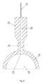
本発明の傷の治療器具を図1に示す。本器具は、超音波トランスデューサ2に接続された発生器1と、トランスデューサ2の遠位端に設けられた超音波ホーン(horn)3と、ホーン3の遠位端に設けられたキャビテーションチャンバ4と、を具えている。ホーン3は、キャビテーションチャンバ4の外側頂部に設けられている。キャビテーションチャンバ4の外側頂部は、チャンバの最上部又はその近くの部分に関する。超音波ホーンは、それが傷の中に長手方向の超音波を伝送する場合、チャンバの頂部に位置している。キャビテーションチャンバ4は、下部が開口する内側空洞5を具えており、図示しない流体のアトマイズ処理していない接触媒体を保持し得る。跳ね上げをなくすことで、キャビテーションチャンバは、患者が治療する間に汚染から本器具の使用者及び周囲の環境を保護する。キャビテーションチャンバの中に保持される接触媒体は、液体、ゲル、又はこれと同じような流体媒体でよい。超音波に晒す際にアトマイズ処理していない接触媒体が好適であるが、アトマイズ処理した接触媒体もまた使用してもよい。
The wound healing instrument of the present invention is shown in FIG. The instrument includes a generator 1 connected to an
接触媒体は、食塩水でよい。また、接触媒体は、抗凝固剤、抗炎症薬、抗ウイルス薬、抗生物質、又はビタミンといった薬物及び又は他の治療薬を含む溶液でもよいがこれらに限定されない。薬物又は他の治療薬を接触媒体の中に懸濁及び/又は溶解させてもよい。 The contact medium may be saline. The contact medium may also be a solution containing, but not limited to, drugs such as anticoagulants, anti-inflammatory drugs, antiviral drugs, antibiotics, or vitamins and / or other therapeutic agents. The drug or other therapeutic agent may be suspended and / or dissolved in the contact medium.
図1のように、キャビテーションチャンバ4は、単一の部分を形成するようにホーン3に一体となっていてもよい。代替的に、キャビテーションチャンバ4は、機械的又は他の手段によってホーン3に取り付けられる別の部品でもよい。ホーン3にキャビテーションチャンバ4を取り付けるための手段は、使用者がキャビテーションチャンバ4を取り外して交換し得るようなものである。取り外し可能なキャビテーションチャンバにより、使用者が治療すべき傷に適合するように治療領域の大きさ及び又は形態を調整できる。
As shown in FIG. 1, the
図1のように、ホーン3は、単一の部分を形成するようにトランスデューサ2に一体となっていてもよい。代替的に、ホーン3は、単独又はキャビテーションチャンバ4と一緒に機械的又は他の手段によってトランスデューサ2に取り付けられる別の部品でもよい。トランスデューサ2にホーン3を取り付けるための手段は、使用者がホーンを取り外して交換し得るようなものである。取り外し可能なホーンにより、使用者が放射される超音波のパラメータを調整できる。そのような調整を行うことで、本器具が選択した接触媒体の内部に所望のタイプのキャビテーションを誘起し及び/又は選択した接触媒体に適合する超音波を放射するよう、使用者が設定する。また、取り外し可能なホーンにより、本器具が治療すべき傷のタイプに最も適した超音波を放射するよう、使用者が設定できる。
As shown in FIG. 1, the
使用する超音波の周波数は、約15kHzから20MHzに変化する。好適な低周波の範囲は、約20kHzから100kHzである。より好適な低周波の範囲は、約25kHzから50kHzである。推奨される低周波は、約30kHzである。好適な高周波の範囲は、約0.7MHzから3MHzである。より好適な高周波の範囲は、約0.7MHzから3MHzである。推奨される高周波は、約0.7MHzである。また、使用する超音波の振幅は、約1ミクロン以上に変化する。好適な低周波の振幅は、約30ミクロンから100ミクロンである。推奨される低周波の振幅は、約100ミクロンである。高周波の振幅は、約1ミクロン以上とすることができる。好適な高周波の振幅は、約5ミクロンである。推奨される高周波の振幅は、約10ミクロンである。低周波の超音波を使用することが、好適な治療方法である。 The frequency of the ultrasonic wave used varies from about 15 kHz to 20 MHz. A suitable low frequency range is about 20 kHz to 100 kHz. A more preferred low frequency range is about 25 kHz to 50 kHz. The recommended low frequency is about 30 kHz. A suitable high frequency range is about 0.7 MHz to 3 MHz. A more preferred high frequency range is about 0.7 MHz to 3 MHz. The recommended high frequency is about 0.7 MHz. Further, the amplitude of the ultrasonic wave used changes to about 1 micron or more. The preferred low frequency amplitude is about 30 to 100 microns. The recommended low frequency amplitude is about 100 microns. The amplitude of the high frequency can be about 1 micron or more. A preferred high frequency amplitude is about 5 microns. The recommended high frequency amplitude is about 10 microns. The use of low frequency ultrasound is the preferred treatment method.
図2は、トランスデューサ2及びホーン3を通り抜けてキャビテーションチャンバ4の内側空洞5の中に設けられた供給口7に至る供給流路6を具える本発明の代替的な形態の断面図を表している。供給流路6の近位端に結合されたチューブ8が、図示しない接触媒体を供給流路6に運ぶ。そして、接触媒体は供給流路6を通ってキャビテーションチャンバ4の内側空洞5の中に流れる。接触媒体を供給流路6を通してキャビテーションチャンバ4の内側空洞5の中に押し出すように、チューブ8を図示しないポンプに取り付けてもよい。キャビテーションチャンバ4の内側空洞5の中に接触媒体を押し出すことで、ポンプユニットが治療される傷の面に対して全体的な正圧を形成する。
FIG. 2 represents a cross-sectional view of an alternative form of the invention comprising a
図3は、ホーン3を通り抜けてキャビテーションチャンバ4の内側空洞5の中の供給口7に至る供給流路6と、キャビテーションチャンバ4の内側空洞5の中に設けられた排出口10からホーン3を通り抜けて延びる排出流路9とを具える本発明の代替的な形態の断面図を表している。供給流路6の近位端に結合されたチューブ8が、接触媒体を供給流路6に運ぶ。接触媒体を、器具の上に配置された点滴袋又はこれと同じような容器によって、供給流路6の中に重力送りしてもよい。そして、接触媒体は供給流路6を通ってキャビテーションチャンバ4の内側空洞5の中に流れ、創傷床に新たな接触媒体及び/又は薬物を送出する。キャビテーションチャンバ4の内側空洞5の中に渦を形成しながら、放射される超音波が接触媒体を排出流路9まで押し上げる。排出流路9に取り付けられたチューブ11が排出された接触媒体を本発明の外に送り出す。
3 shows that the
図3に示すように、チューブ8をポンプに取り付けて、接触媒体を供給流路6を通してキャビテーションチャンバ4の内部空洞5の中に押し出してもよい。キャビテーションチャンバ4の内部空洞5に出入りする接触媒体の流れに関する差を形成するために、排出口10及び/又は排出流路9が、1又はそれ以上の場所で供給流路6及び供給口7の中の最小の内径よりも小さな内径を有している。キャビテーションチャンバ4の内部空洞5に出入りする接触媒体の流れの得られる差により、治療される傷の表面に対して全体的な正圧を保持する一方、排出流路9によって接触媒体がキャビテーションチャンバ4の内部空洞5を出入りし得る。キャビテーションチャンバ4の内部空洞5から出ることで、接触媒体は取り除かれた壊死組織、病原菌、及び/又は他の汚染物質を傷から運び出す。
As shown in FIG. 3, a tube 8 may be attached to the pump to push the contact medium through the
代替的に、チューブ11を、図3に示すように真空装置に取り付けて、接触媒体をキャビテーションチャンバ4の内部空洞5の外に排出流路9まで引き出してもよい。キャビテーションチャンバ4の内部空洞5から接触媒体を引くと、真空ユニットが供給流路6からキャビテーションチャンバ4の内部空洞5の中に接触媒体を引き入れる。キャビテーションチャンバ4の内部空洞5に出入りする接触媒体の流れに関する差を形成するために、供給流路及び/又は供給口7が、1又はそれ以上の場所で排出流路9及び排出口10の中の最小の内径よりも小さな内径を有している。キャビテーションチャンバ4の内部空洞5に出入りする接触媒体の流れの得られる差により、治療される傷の表面に対して全体的な負圧を保持する一方、新たな接触媒体が供給流路7を通してキャビテーションチャンバ4の内部空洞5を出入りするように流れ得る。
Alternatively, the tube 11 may be attached to a vacuum apparatus as shown in FIG. 3 to draw the contact medium out of the
さらに別の代替的な構成では、本発明は、図3に示すように、チューブ11に取り付けられた真空装置及びチューブ8に取り付けられたポンプを含んでいる。真空ユニット及びポンプを使用して、キャビテーションチャンバ4の内部空洞5に出入りする接触媒体の流れの差を形成する。さらに、真空装置及びポンプを共同して使用することで、使用者が治療する傷の表面に加える圧力を調整及び調節できる。また、真空装置及びポンプを共同して使用することで、使用者が傷の表面に対して全体的な負圧及び正圧を加えるのを繰り返すことが可能となる。
In yet another alternative configuration, the present invention includes a vacuum device attached to tube 11 and a pump attached to tube 8, as shown in FIG. A vacuum unit and a pump are used to create a difference in the flow of contact medium in and out of the
図4は、超音波トランスデューサ2と、トランスデューサ2の遠位端に設けられたホーン3と、ホーン3の遠位端の超音波チップ(tip)12と、ホーン3の遠位端又はその近くに設けられたキャビテーションチャンバ4と、を具える本発明の代替的な構成の断面図を示す。キャビテーションチャンバ4は、その基部が開口した内部空洞5を具えており、内部空洞5が図示しないアトマイズ処理していない流体の接触媒体を保持できる。キャビテーションチャンバ4は、チップ12を包んでもよいが必ずしもこれに限定されない。このチップをキャビテーションチャンバの中又は外に設けてもよい。キャビテーションチャンバ4は、ホーン3及び/又はチップ12と一体であってもよい。代替的に、キャビテーションチャンバ4は、機械的な手段13によってホーン3及び/又はチップ12に取り付けられた別の部品でもよい。キャビテーションチャンバを取り付けるための化学的又は磁気的といったこれらに限定されない他の手段が、同様に有効である。ホーン3又はチップ12にキャビテーションチャンバ4を取り付けるための手段は、使用者がキャビテーションチャンバ4を取り外し又は交換し得るようなものでよい。取り外し可能なキャビテーションチャンバにより、使用者は治療領域の大きさ及び/又は構成を調整できる。チップ12を、ホーン3、キャビテーションチャンバ4の外側頂部、及び/又はキャビテーションチャンバ12の内側頂部と一体化してもよい。代替的にチップ12は、ホーン3、キャビテーションチャンバ4の外側頂部、キャビテーションチャンバ12の内側頂部、又はそれらを組み合わせた別の部品であってもよい。ホーン3、キャビテーションチャンバ4の外側頂部、又はキャビテーションチャンバ4の内側頂部にチップ12を取り付けるための手段が、使用者によってチップ12を取り外し又は交換できるようなものであってもよい。取り外し可能なチップにより、治療する傷及び使用する接触媒体に適合するように、使用者が超音波の送出を調整できる。キャビテーションチャンバの内側頂部は、内部空洞5の上部又はその近くの部分に関する。超音波チップは、傷の中に長手方向の超音波を伝送する場合に内部空洞の頂部の近くに設けられている。
FIG. 4 shows an
さらに図4に示すように、本構成は、トランスデューサ2及びホーン3を通り抜けてチップ12の中に設けられた供給口7に至る供給流路6を具えている。供給流路6の近位端に接続されたチューブ8が、供給流路6に接触媒体を運ぶ。そして接触媒体は、供給流路6を通ってキャビテーションチャンバ4の内部空洞5の中に流れる。供給流路6を通してキャビテーションチャンバ4の内部空洞の中に接触媒体を押し出すように、チューブ8をポンプに取り付けてもよい。
Further, as shown in FIG. 4, this configuration includes a
図5は、本器具の一部を通り抜けてチップ12の中に設けられた供給口7に至る供給流路6と、チップ12の中に設けられた排出口10から延びて本器具の一部を通り抜ける排出流路9と、を具える本発明の代替的な構成の断面図を示す。供給流路6の近位端に接続されたチューブ8が、供給流路6に接触媒体を運ぶ。そして、接触媒体は、供給流路6を通ってキャビテーションチャンバ4の内部空洞5の中に流れる。キャビテーションチャンバ4の内側空洞5の中に渦を形成しながら、放射された超音波が排出口10を通して排出流路9に接触媒体を押し上げる。排出口9に取り付けられたチューブ11が、排出された接触媒体を器具の外に運ぶ。
FIG. 5 shows a part of the instrument extending from a
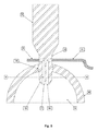
キャビテーションチャンバ4は、図6aから6bに詳細に示すように、その基部が開口した内側空洞5を具えている。使用後に殺菌できるように、キャビテーションチャンバ4を全体的に加圧滅菌に耐える金属又はプラスチック材料で構成してもよい。また、キャビテーションチャンバ4をポリマー又は樹脂といったこれらに限定されない柔軟な材料で全体的に構成してもよい。代替的に、キャビテーションチャンバ4は、金属の頂部14及び柔軟な基部15を具えてもよい。柔軟なベース15をプラスチック又はポリマーといったこれらに限定されない様々な材料で構成してもよい。柔軟なベース15を構成するのに使用する材料は、薄膜又はシートである。代替的に、柔軟なベース15を構成するのに使用する材料が十分に硬いことで、チャンバが幾何学的な形状を保持し得る。キャビテーションチャンバ4の全体又はその一部を柔軟な材料で構成することで、本発明の傷の治療器具を患者に押し付けた場合に、キャビテーションチャンバ4が患者の体の凹凸に適合できる。患者の体に適合することで、治療の際に接触媒体を保持するように、キャビテーションチャンバ4が良好な密着を形成し得る。液体のシール剤16をキャビテーションチャンバ4の基部に付けることで、キャビテーションチャンバの基部と患者の皮膚との密着をさらに促進する。液体のシール剤16は、シリコンゲル、医療用ゲル、医療用接着剤、又は水を具えてもよいが、これらに限定されない。さらに、キャビテーションチャンバ4の全体又はその一部を柔軟な材料で構成することで、詰まったトイレを治すために吸引具を使用する配管工と同じような動作及び効果により、本器具を押し下げ及び持ち上げることによって、使用者が傷に対して全体的な正圧及び負圧を交互に形成し得る。本器具を押し込み易くするために、キャビテーションチャンバ4の基部は図7に例を示すようにアコーディオン状の構成を有してよい。
The
図6aから図6bに戻ると、キャビテーションチャンバ4の側面にある供給口17及び排出口18により、接触媒体を内部空洞5の中に導入し内部空洞5から排出し得る。供給ポート17に取り付けられたチューブ19が、キャビテーションチャンバ4に接触媒体を運ぶ。排出ポート18に取り付けられたチューブ20が、排出された接触媒体をキャビテーションチャンバ4の外に運ぶ。供給ポート17を通って内部空洞5の中に接触媒体を押し出すように、チューブ19をポンプに取り付けてもよい。内部空洞5の中に接触媒体を押し出すことで、ポンプが傷の表面に対して全体的な正圧を形成する。内部空洞5を出入りする接触媒体の流れに関する差を形成するために、排出ポート18は、1又はそれ以上の場所で供給ポート17の最小の内径よりも小さい内径を有する。内部空洞5を出入りする接触媒体の流れの得られた差により、治療される傷の表面に対して全体的な正圧を保持する一方、接触媒体が排出ポート18の外に流れ得る。接触媒体がキャビテーションチャンバから出ることで、接触媒体は取り除かれた壊死組織、病原菌、及び/又は他の汚染物質を傷から運び出す。
Returning to FIG. 6 b from FIG. 6 a, the contact medium can be introduced into the
図6aから6bに示すように、接触媒体を内部空洞5の外に引き出すように、チューブ20を真空装置に取り付けてもよい。接触媒体を内部空洞5から引き出すことで、真空装置が傷を治療する表面に対して全体的な負圧を形成する。内部空洞5を出入りする接触媒体の流れに関する差を形成するために、供給ポート17は、1又はそれ以上の場所で排出ポート18の最小の内径よりも小さい内径を有する。内部空洞5を出入りする接触媒体の流れの得られた差により、治療される傷の表面に対して全体的な負圧を保持する一方、新たな接触媒体が供給ポート17を通って内部空洞5の中に流入し得る。
As shown in FIGS. 6 a to 6 b, the
さらに別の代替的な構成では、図6aから図6bに示すキャビテーションチャンバが、チューブ20に取り付けられた真空ユニット及びチューブ19に取り付けられたポンプを含んでいる。真空ユニット及びポンプを共に使用して、内部空洞5に出入りする接触媒体の流量差を形成する。さらに、真空ユニット及びポンプを共に使用することで、使用者が治療される傷の表面に加わる全体的な圧力を調整及び調節し得る。また、真空ユニット及びポンプを共に使用することで、使用者が傷の表面に対して全体的な負圧及び正圧を交互に繰り返し加えることができる。
In yet another alternative configuration, the cavitation chamber shown in FIGS. 6 a-6 b includes a vacuum unit attached to
図6aから図6bに示すように、キャビテーションチャンバ4をホーン3及び/又はチップ12から取り外すように、ホーン3及び/又はチップ12にキャビテーションチャンバ4に結合するための機械的な手段は、ホーン3の遠位端に設けられた突起部22を受容する受容部21を、キャビテーションチャンバ4の外側頂部に具えている。その内側頂部に、キャビテーションチャンバ4は、チップ12の近位端に設けられた突起部24を受容する受容部23を有している。突起部22及び24及び受容部21及び23にネジを切ってもよい。キャビテーションチャンバの外側頂部は、内部空洞の頂部の反対側の部分である。
The mechanical means for coupling the
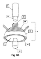
図8aから8bは、ホーン3及び/又はチップ12にキャビテーションチャンバを取り付けるための代替的な機械的な手段を示す。キャビテーションチャンバ4は、その外側頂部に、ホーン3の遠位端に設けられた受容部26に嵌る突起部25を有している。キャビテーションチャンバ4は、内側頂部に、チップ12の近位端に設けられた受容部28に嵌る金属の突起部27を有している。突起部25及び27及び受容部26及び28にネジを切ってもよい。キャビテーションチャンバは、内側−外側−頂部−突起部−受容部の組み合わせを具えている。他の機械的な手段は、キャビテーションチャンバをチップ及び/又はホーンと別にできる点で同様に有効である。さらに、キャビテーションチャンバの内側頂部又はホーンにチップを取り付けるための、化学的又は磁気的といったこれらに限定されない機械式以外の手段が、治療の際にチップを固定できる点で同様に有効である。
FIGS. 8 a to 8 b show an alternative mechanical means for attaching the cavitation chamber to the
キャビテーションチャンバの概略3次元形状は、図6aから6b及び図8aから8bに示すような放物線状、ピラミッド状、矩形状、楕円形、又は多角形でよい。同様に、キャビテーションチャンバの基部の形状は、図6aから6b及び図8aから8bに示すような円形、楕円形、矩形、三角形、又は多角形でよい。列挙した形状は単に典型例であって、可能性のある構成の排他的又は包括的なリストを意味するものではない。 The approximate three-dimensional shape of the cavitation chamber may be parabolic, pyramidal, rectangular, elliptical, or polygonal as shown in FIGS. 6a to 6b and FIGS. 8a to 8b. Similarly, the shape of the base of the cavitation chamber may be circular, elliptical, rectangular, triangular or polygonal as shown in FIGS. 6a to 6b and FIGS. 8a to 8b. The listed shapes are merely exemplary and do not imply an exclusive or comprehensive list of possible configurations.
図9は、本発明とともに使用するための超音波チップを示しており、その遠位端に放射面29を、その近位端に取り付け手段24を具えている。取り付け手段24は、機械的、化学的、又は磁気的なものであるがこれらに限定されず、取り付け手段24は治療の際にキャビテーションチャンバの内側頂部及び/又は超音波ホーンの遠位端に本器具に固定するよう機能する。放射面29は、治療中に、キャビテーションチャンバによって保持された接触媒体の中にキャビテーションを誘起する超音波を放射する。
FIG. 9 shows an ultrasonic tip for use with the present invention, comprising a radiating
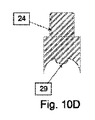
図10aから10dは、本発明とともに使用する様々な超音波チップの構成の断面図を示す。超音波チップは、遠位端に、超音波が放射される放射面29を具えている。放射面29は、図10a及ぶ図10bにそれぞれ示すように凸状又は凹状の形状を具えている。代替的に、図10cに示すように、放射面28が平らな形状を具えてもよい。放射面29は、図10dに示すように、外側の凹状の形状によって囲まれた内側の凸状の形状を具えてもよい。また、放射面29の他の形状も有効であり、上述の例示した形状は、排他的又は包括的なリストを意図するものではない。図10aから10dに示すような内側の輪郭のように、超音波チップの放射面の外側の周縁部は、円形、楕円形、矩形、三角形、又は多角形といった様々な形状を取ってもよいが、これらに限定されない。
Figures 10a to 10d show cross-sectional views of various ultrasonic tip configurations for use with the present invention. The ultrasonic tip has a
特定の実施例及び使用方法を本書で図示及び説明したが、図示した特定の実施例及び方法を同じ目的を達成するよう見積もられた配置に代えてもよいことが、当業者にとって明らかであろう。上記の説明は具体例であって限定的なものではないことに留意されたい。上記及び他の使用方法の組み合わせとともに上記及び他の実施例の組み合わせは、本開示を参照することにより当業者にとって明らかとなろう。本発明の範囲は、添付の特許請求の範囲を参照してこのような特許請求の範囲に与えられたものと等価な包括的なものとともに、判断すべきである。 While specific embodiments and methods of use have been illustrated and described herein, it will be apparent to those skilled in the art that the specific embodiments and methods illustrated may be substituted for configurations that are estimated to accomplish the same purpose. Let's go. It should be noted that the above description is illustrative and not restrictive. Combinations of the above and other examples, as well as combinations of the above and other uses, will be apparent to those of skill in the art upon reviewing the present disclosure. The scope of the invention should be determined with reference to the appended claims, along with the generic equivalents given to such claims.
Claims (83)
a.発生器と、
b.前記発生器に接続された超音波トランスデューサと、
c.前記超音波トランスデューサの遠位端のホーンと、
d.前記ホーンの遠位端のキャビテーションチャンバと、
を具えることを特徴とする器具。 A wound healing device,
a. A generator,
b. An ultrasonic transducer connected to the generator;
c. A horn at the distal end of the ultrasonic transducer;
d. A cavitation chamber at the distal end of the horn;
A device characterized by comprising.
前記ポンプが接触媒体を前記キャビテーションチャンバの中に押し込むことを特徴とする請求項13に記載の器具。 And a pump attached to the tube,
14. The instrument of claim 13, wherein the pump pushes a contact medium into the cavitation chamber.
前記排出口及び/又は前記排出流路が、1又はそれ以上の場所で前記供給流路及び供給口の最小の内径よりも小さい内径を有していることを特徴とする請求項13に記載の器具。 And further comprising a discharge flow path beginning at a discharge opening in the cavitation chamber and passing through at least a portion of the instrument
14. The discharge port and / or the discharge flow channel has an inner diameter that is smaller than a minimum inner diameter of the supply flow channel and the supply port at one or more locations. Instruments.
前記真空装置が前記キャビテーションチャンバから接触媒体を排出することを特徴とする請求項20に記載の器具。 And a vacuum device attached to the discharge tube,
21. The instrument of claim 20, wherein the vacuum device evacuates the contact medium from the cavitation chamber.
前記供給口及び/又は前記供給流路が、1又はそれ以上の場所で前記排出流路及び排出口の最小の内径よりも小さい内径を有していることを特徴とする請求項20に記載の器具。 And a supply channel that passes through at least a portion of the instrument to a supply port in the cavitation chamber,
The said supply port and / or the said supply flow path have an internal diameter smaller than the minimum internal diameter of the said discharge flow path and a discharge port in one or more places. Instruments.
前記空洞が前記チャンバの基部で開口していることを特徴とするキャビテーションチャンバ。 With internal cavities,
A cavitation chamber characterized in that the cavity opens at the base of the chamber.
前記ポンプが前記内部空洞の中に接触媒体を押し込むことを特徴とする請求項46に記載のチャンバ。 And a pump attached to the tube,
The chamber of claim 46, wherein the pump pushes a contact medium into the internal cavity.
前記排出ポートが、1又はそれ以上の場所で前記供給ポートの最小の内径よりも小さい内径を有していることを特徴とする請求項44に記載のチャンバ。 In addition, it has a discharge port,
45. The chamber of claim 44, wherein the exhaust port has an inner diameter that is less than a minimum inner diameter of the supply port at one or more locations.
前記真空装置が前記内部空洞から接触媒体を排出することを特徴とする請求項51に記載のチャンバ。 Furthermore, it comprises a vacuum device attached to the tube,
52. The chamber of claim 51, wherein the vacuum device evacuates a contact medium from the internal cavity.
前記供給ポートが、1又はそれ以上の場所で前記排出ポートの最小の内径よりも小さい内径を有していることを特徴とする請求項49に記載のチャンバ。 In addition, it has a supply port,
50. The chamber of claim 49, wherein the supply port has an inner diameter that is less than a minimum inner diameter of the exhaust port at one or more locations.
b.前記放射面が、キャビテーションチャンバの中に保持された接触媒体の中にキャビテーションを誘起し得る超音波を放射することを特徴とする超音波チップ(tip)。 a. With a radiating surface at the distal end,
b. An ultrasonic tip, wherein the radiation surface emits ultrasonic waves capable of inducing cavitation in a contact medium held in a cavitation chamber.
a.前記傷の表面に流体の接触媒体を置くステップと、
b.超音波で前記接触媒体の中にキャビテーションを誘起させるステップと、
を具えることを特徴とする方法。 A method of treating wounds,
a. Placing a fluid contact medium on the surface of the wound;
b. Inducing cavitation in the contact medium with ultrasound,
A method characterized by comprising.
前記キャビテーションチャンバが前記接触媒体を保持することを特徴とする請求項65に記載の方法。 And further comprising the step of placing a cavitation chamber on the surface of the wound,
66. The method of claim 65, wherein the cavitation chamber holds the contact medium.
Applications Claiming Priority (2)
| Application Number | Priority Date | Filing Date | Title |
|---|---|---|---|
| US11/474,695 US20070299369A1 (en) | 2006-06-26 | 2006-06-26 | Ultrasound wound care device and method |
| PCT/US2007/071166 WO2008002773A2 (en) | 2006-06-26 | 2007-06-14 | Ultrasound wound care device and method |
Publications (2)
| Publication Number | Publication Date |
|---|---|
| JP2009541015A true JP2009541015A (en) | 2009-11-26 |
| JP2009541015A5 JP2009541015A5 (en) | 2011-08-11 |
Family
ID=38846395
Family Applications (1)
| Application Number | Title | Priority Date | Filing Date |
|---|---|---|---|
| JP2009518440A Pending JP2009541015A (en) | 2006-06-26 | 2007-06-14 | Ultrasonic wound treatment apparatus and method |
Country Status (7)
| Country | Link |
|---|---|
| US (1) | US20070299369A1 (en) |
| EP (1) | EP2032112A4 (en) |
| JP (1) | JP2009541015A (en) |
| KR (1) | KR20090039734A (en) |
| CN (1) | CN101505706A (en) |
| AU (1) | AU2007265288A1 (en) |
| WO (1) | WO2008002773A2 (en) |
Cited By (2)
| Publication number | Priority date | Publication date | Assignee | Title |
|---|---|---|---|---|
| JP2013502246A (en) * | 2009-08-18 | 2013-01-24 | アイ、テック、ケア | Parameters for an ultrasonic device with means for generating a high-density ultrasonic beam |
| JP2015530164A (en) * | 2012-10-01 | 2015-10-15 | メンリッケ・ヘルス・ケア・アーベー | Wound therapy device |
Families Citing this family (24)
| Publication number | Priority date | Publication date | Assignee | Title |
|---|---|---|---|---|
| US8235919B2 (en) | 2001-01-12 | 2012-08-07 | Celleration, Inc. | Ultrasonic method and device for wound treatment |
| US20040030254A1 (en) * | 2002-08-07 | 2004-02-12 | Eilaz Babaev | Device and method for ultrasound wound debridement |
| CN101522263A (en) * | 2006-08-25 | 2009-09-02 | 艾拉兹·巴巴耶夫 | Portable ultrasound device for the treatment of wounds |
| US8491521B2 (en) | 2007-01-04 | 2013-07-23 | Celleration, Inc. | Removable multi-channel applicator nozzle |
| US8048044B2 (en) * | 2007-08-14 | 2011-11-01 | Stryker Corporation | Drug delivery system |
| US20090198157A1 (en) * | 2008-02-01 | 2009-08-06 | Eilaz Babaev | Ultrasound moxibustion method and device |
| BRPI0822017A2 (en) * | 2008-04-11 | 2015-07-21 | Gp Investimenti S R L | Handle for ultrasound treatment in human tissue. |
| ES2546379T3 (en) * | 2008-07-23 | 2015-09-23 | Enraf Nonius B.V. | Ultrasound treatment head for an ultrasound patient treatment device |
| US9414968B2 (en) | 2008-09-05 | 2016-08-16 | Smith & Nephew, Inc. | Three-dimensional porous film contact layer with improved wound healing |
| KR101358374B1 (en) * | 2009-07-30 | 2014-02-05 | 알마 레이저 엘티디. | A sonotrode |
| PL2654896T3 (en) | 2010-12-22 | 2020-03-31 | Brh Medical Ltd. | Skin ulcer treatment |
| WO2012162287A1 (en) † | 2011-05-26 | 2012-11-29 | Kci Licensing, Inc. | Systems and methods of stimulation and activation of fluids for use with instillation therapy |
| KR20140039024A (en) | 2011-06-07 | 2014-03-31 | 스미쓰 앤드 네퓨 피엘씨 | Wound contacting members and methods |
| US20130304000A1 (en) * | 2012-05-14 | 2013-11-14 | Christian James Pentell | Body piercing cleansing and sanitation device |
| US9050053B2 (en) * | 2013-02-15 | 2015-06-09 | Naimco, Inc. | Ultrasound device with cavity for conductive medium |
| CN104338190A (en) * | 2013-07-25 | 2015-02-11 | 厚凯(北京)医疗科技有限公司 | Ultrasonic non-contact wound debridement and treatment apparatus capable of enhancing cavitation effect |
| WO2015080901A1 (en) | 2013-11-26 | 2015-06-04 | Celleration Inc. | Systems and methods for producing and delivering ultrasonic therapies for wound treatment and healing |
| EP3527180B1 (en) * | 2014-05-09 | 2021-01-06 | 3M Innovative Properties Company | Debriding dressing for use with negative pressure and fluid instillation |
| CN105030399A (en) * | 2015-06-19 | 2015-11-11 | 李建锋 | Burn rehabilitation therapy apparatus for general surgery department |
| US9586062B2 (en) | 2015-07-06 | 2017-03-07 | Eurocomponents, Inc. | Low frequency ultrasound device with computer-controlled monitoring |
| KR101692280B1 (en) * | 2015-07-15 | 2017-01-17 | (주)클래시스 | Apparatus and method for generating vaccum pulse for medical use |
| CN110787379A (en) * | 2019-11-08 | 2020-02-14 | 昆明医科大学 | Melanin treatment system |
| CN110772723A (en) * | 2019-11-08 | 2020-02-11 | 昆明医科大学 | Skin tissue treatment system |
| KR102488054B1 (en) * | 2022-07-22 | 2023-01-13 | 조대희 | Multi axis ultrasonic torsion energy injection system and method thereof |
Family Cites Families (10)
| Publication number | Priority date | Publication date | Assignee | Title |
|---|---|---|---|---|
| DE19615342C1 (en) * | 1996-04-18 | 1997-10-09 | Siemens Ag | Therapy appts. with optical positioning device |
| US7004933B2 (en) * | 1998-05-29 | 2006-02-28 | Light Bioscience L.L.C. | Ultrasound enhancement of percutaneous drug absorption |
| US20040073115A1 (en) * | 2000-08-24 | 2004-04-15 | Timi 3 Systems, Inc. | Systems and methods for applying ultrasound energy to increase tissue perfusion and/or vasodilation without substantial deep heating of tissue |
| US20040030254A1 (en) * | 2002-08-07 | 2004-02-12 | Eilaz Babaev | Device and method for ultrasound wound debridement |
| US7470240B2 (en) * | 2004-10-22 | 2008-12-30 | General Patent, Llc | Pressure pulse/shock wave therapy methods and an apparatus for conducting the therapeutic methods |
| IL155546A (en) * | 2003-04-22 | 2010-06-16 | Healfus Ltd | Apparatus for treatment of damaged tissue |
| GB0409292D0 (en) * | 2004-04-27 | 2004-06-02 | Smith & Nephew | Apparatus with ultrasound |
| CN1803225A (en) * | 2005-11-29 | 2006-07-19 | 东南大学 | Low frequency focused supersonic generating device for tumor supersonic radiation microbubble agent |
| US9585977B2 (en) * | 2006-02-24 | 2017-03-07 | Nanovibronix, Inc | System and method for surface acoustic wave treatment of skin |
| CN102671312A (en) * | 2006-04-07 | 2012-09-19 | 史密夫和内修有限公司 | Controlling acoustic modes in tissue healing applications |
-
2006
- 2006-06-26 US US11/474,695 patent/US20070299369A1/en not_active Abandoned
-
2007
- 2007-06-14 CN CNA2007800316924A patent/CN101505706A/en active Pending
- 2007-06-14 JP JP2009518440A patent/JP2009541015A/en active Pending
- 2007-06-14 EP EP07798535A patent/EP2032112A4/en not_active Withdrawn
- 2007-06-14 AU AU2007265288A patent/AU2007265288A1/en not_active Abandoned
- 2007-06-14 KR KR1020097001667A patent/KR20090039734A/en not_active Application Discontinuation
- 2007-06-14 WO PCT/US2007/071166 patent/WO2008002773A2/en active Application Filing
Cited By (2)
| Publication number | Priority date | Publication date | Assignee | Title |
|---|---|---|---|---|
| JP2013502246A (en) * | 2009-08-18 | 2013-01-24 | アイ、テック、ケア | Parameters for an ultrasonic device with means for generating a high-density ultrasonic beam |
| JP2015530164A (en) * | 2012-10-01 | 2015-10-15 | メンリッケ・ヘルス・ケア・アーベー | Wound therapy device |
Also Published As
| Publication number | Publication date |
|---|---|
| US20070299369A1 (en) | 2007-12-27 |
| WO2008002773A3 (en) | 2008-11-20 |
| AU2007265288A1 (en) | 2008-01-03 |
| KR20090039734A (en) | 2009-04-22 |
| CN101505706A (en) | 2009-08-12 |
| EP2032112A2 (en) | 2009-03-11 |
| EP2032112A4 (en) | 2010-04-07 |
| WO2008002773A2 (en) | 2008-01-03 |
Similar Documents
| Publication | Publication Date | Title |
|---|---|---|
| JP2009541015A (en) | Ultrasonic wound treatment apparatus and method | |
| AU2007206054B2 (en) | System and method for treating a wound using ultrasonic debridement | |
| CN101674790B (en) | Systems and methods for nasal irrigation | |
| US20080082039A1 (en) | Ultrasound Liquid Delivery Device | |
| JP2010501285A (en) | Instruments and methods for the treatment of wounds with ultrasound and pressure therapy instruments | |
| CN110602998B (en) | Method for reducing or removing biofilm | |
| KR20070122545A (en) | Wound treating apparatus and method | |
| US20080119779A1 (en) | Method of Treating Lumens, Cavities, and Tissues of the Body with an Ultrasound Delivered Liquid. | |
| JP2010509944A (en) | Ultrasonic fluid delivery device and method for delivering fluid to the body using ultrasonic energy | |
| RU132727U1 (en) | DEVICE FOR ULTRASONIC TREATMENT OF THE SKY ALMONDS IN THE TREATMENT OF CHRONIC TONSILLITIS | |
| RU67867U1 (en) | ORAL IRRIGATION DEVICE | |
| JP2020022651A (en) | Solution treatment processing instrument |
Legal Events
| Date | Code | Title | Description |
|---|---|---|---|
| RD04 | Notification of resignation of power of attorney |
Free format text: JAPANESE INTERMEDIATE CODE: A7424 Effective date: 20100227 |
|
| A521 | Request for written amendment filed |
Free format text: JAPANESE INTERMEDIATE CODE: A523 Effective date: 20100604 |
|
| A621 | Written request for application examination |
Free format text: JAPANESE INTERMEDIATE CODE: A621 Effective date: 20100604 |
|
| A072 | Dismissal of procedure [no reply to invitation to correct request for examination] |
Free format text: JAPANESE INTERMEDIATE CODE: A073 Effective date: 20111011 |