JP2008043184A - Power supply unit, and method for synchronously operating power conversion device - Google Patents
Power supply unit, and method for synchronously operating power conversion device Download PDFInfo
- Publication number
- JP2008043184A JP2008043184A JP2007138054A JP2007138054A JP2008043184A JP 2008043184 A JP2008043184 A JP 2008043184A JP 2007138054 A JP2007138054 A JP 2007138054A JP 2007138054 A JP2007138054 A JP 2007138054A JP 2008043184 A JP2008043184 A JP 2008043184A
- Authority
- JP
- Japan
- Prior art keywords
- power
- output
- voltage
- power supply
- phase
- Prior art date
- Legal status (The legal status is an assumption and is not a legal conclusion. Google has not performed a legal analysis and makes no representation as to the accuracy of the status listed.)
- Pending
Links
Images


Landscapes
- Control Of Eletrric Generators (AREA)
- Inverter Devices (AREA)
Abstract
Description
本発明は、ガスタービン発電機等の分散型発電装置と、前記発電装置により発電された電力を所要の周波数および電圧の交流電力に変換して負荷へ供給するインバータ装置などの電力変換装置とからなるユニット化された電力供給装置に係り、特に複数台の電力供給装置を並列接続し、商用電源系統から切り離された負荷に並列運転により電力を供給する電力供給システムに用いられる電力供給装置に関する。 The present invention includes a distributed power generator such as a gas turbine generator, and a power converter such as an inverter that converts the power generated by the power generator into AC power having a required frequency and voltage and supplies the AC power to a load. The present invention relates to a unitized power supply apparatus, and more particularly to a power supply apparatus used in a power supply system in which a plurality of power supply apparatuses are connected in parallel and power is supplied to a load disconnected from a commercial power supply system by parallel operation.
また、本発明は、複数台のインバータ装置(電力変換装置)を並列接続して、商用電源系統から切り離された負荷に並列運転により三相交流電力を供給する際に、各インバータ装置間で出力電圧の同期を取る方法に関する。 In addition, the present invention outputs a plurality of inverter devices (power converters) connected in parallel to each other when supplying three-phase AC power to a load disconnected from a commercial power supply system in parallel operation. The present invention relates to a method for synchronizing voltages.
電圧制御型インバータ装置を含む電力供給装置を複数台並列接続して、負荷へ発電電力を供給する電力供給システムでは、インバータ装置が同じ電圧を出力しても、実際に出力される電圧は、センサ、フィルタ回路の構成部品などの誤差により、完全に一致した電圧を出力することは難しい。その為、通常は、電圧制御型インバータ装置を含む電力供給装置を複数台並列接続して、商用電源系統から切り離された負荷に発電電力を供給する電力供給システムにおいては、複数台の電力供給装置の負荷分担率を均等に保つために、インバータ装置間で互いの情報(電流、電力など)を共有し、出力電圧をコントロールし、負荷の分坦率を均等に保ち、インバータ装置の能力を有効に使用することが提案されている。 In a power supply system in which a plurality of power supply devices including a voltage-controlled inverter device are connected in parallel to supply generated power to a load, even if the inverter device outputs the same voltage, the actually output voltage is It is difficult to output a completely matched voltage due to errors in filter circuit components. Therefore, normally, in a power supply system in which a plurality of power supply devices including a voltage-controlled inverter device are connected in parallel to supply generated power to a load disconnected from a commercial power supply system, the plurality of power supply devices In order to keep the load sharing ratio of the inverters equal, each other's information (current, power, etc.) is shared between the inverter devices, the output voltage is controlled, the load sharing rate is kept even, and the capacity of the inverter devices is made effective It is proposed to use.
しかしながら、上記の負荷分担方法では、複数台の電力供給装置間の情報を共有するための専用ハードウェアなどが必要となり、コスト、信頼性の面でも問題がある。また、電力のコントロールの為に共用されている情報は、インバータ装置に関する情報のみであり、発電装置(ガスタービン発電機、燃料電池など)とインバータ装置などの電力変換装置とが組み合わせて使用されるユニット化された電力供給装置の場合には、インバータ装置が過負荷になる前に、発電装置が過負荷になり、発電装置が停止してしまい、インバータ装置の能力に余裕があるにもかかわらず、発電装置が止まってしまう現象が発生するなどの問題がある。 However, the above load sharing method requires dedicated hardware for sharing information among a plurality of power supply apparatuses, and there is a problem in terms of cost and reliability. Moreover, the information shared for power control is only information related to the inverter device, and the power generator (gas turbine generator, fuel cell, etc.) and the power converter such as the inverter device are used in combination. In the case of a unitized power supply device, before the inverter device is overloaded, the power generation device is overloaded, the power generation device is stopped, and there is a margin in the capacity of the inverter device There is a problem that the power generation device stops.
電圧制御型インバータ装置を複数台並列接続して、負荷へ発電電力を供給する電力供給システムでは、商用電源系統から切り離された負荷へ電力を供給する場合、以下のようなインバータ装置間の同期方法がある。 In a power supply system in which a plurality of voltage-controlled inverter devices are connected in parallel to supply generated power to a load, when supplying power to a load disconnected from a commercial power supply system, the following synchronization method between inverter devices is as follows: There is.
第1に、一台のインバータ装置が親機となり、親機の電圧出力と同期した特別な基準信号をその他のインバータ装置へ出力する。他の(親機以外の)インバータ装置は、その基準信号に同期した出力電圧を形成し、インバータ装置出力電圧の同期を取る。 First, one inverter device serves as a parent device, and outputs a special reference signal synchronized with the voltage output of the parent device to the other inverter devices. Other inverter devices (other than the parent device) form an output voltage synchronized with the reference signal, and synchronize the inverter device output voltage.
第2に、外部コントローラが、複数台のインバータ装置へ位相同期用の基準信号を送信し、その基準信号を元に、各インバータ装置が出力電圧を形成することにより、出力電圧の同期を取る。 Second, an external controller transmits a reference signal for phase synchronization to a plurality of inverter devices, and each inverter device forms an output voltage based on the reference signal, thereby synchronizing the output voltage.
第3に、複数台の内一台のインバータ装置が、自立(電圧制御)モードで起動して電圧を確立後、その他のインバータ装置が連系(電流制御)モードで起動し、電圧位相に同期した並列運転を行い、出力電圧の同期を取る。 Thirdly, after one of the multiple inverter devices is activated in the self-sustaining (voltage control) mode to establish the voltage, the other inverter devices are activated in the interconnected (current control) mode and synchronized with the voltage phase. The parallel operation is performed and the output voltage is synchronized.
上記従来の技術においては、第1と第2の方法のように、すべてのインバータ装置が電圧制御モードで動作する方法と、第3の方法のように、基準となるインバータ装置が電圧制御モード、その他のインバータ装置が電流制御モードとして同期運転を行う方法とが提案されている。しかしながら、上記従来の技術には、以下の課題がある。上記第1と第2の方法のように、すべてのインバータ装置が電圧制御モードで動作する方法においては、各インバータ装置間の出力を同期させるのに同期信号が必要となっているので、同期信号を出力するインバータ装置または外部のコントローラが故障した場合、運転の継続ができなくなる。また、同期信号を伝達する為の信号線が、出力線以外に必要となるので、システムが複雑になる。 In the prior art, as in the first and second methods, a method in which all inverter devices operate in the voltage control mode, and in a third method, the reference inverter device is in the voltage control mode. There has been proposed a method in which another inverter device performs synchronous operation as a current control mode. However, the above conventional techniques have the following problems. In the method in which all inverter devices operate in the voltage control mode as in the first and second methods, a synchronization signal is required to synchronize the output between the inverter devices. If the inverter device or the external controller that outputs is broken, the operation cannot be continued. Further, since a signal line for transmitting the synchronization signal is required in addition to the output line, the system becomes complicated.
また、基準となるインバータ装置が電圧制御モード、その他のインバータ装置が電流制御モードとして運転を行う第3の方法においては、同期信号を用いないので、同期信号の信号線が不要となり、システムが複雑になるという問題については改善される。しかし、基準となるインバータ装置が電圧制御モード、その他のインバータ装置が電流制御モードとして運転を行う必要があるので、基準となる電圧制御モードで運転を行っているインバータ装置に異常が発生すると、運転の継続が困難になること、また、電流制御モードのインバータ装置が急激な負荷変動に対応できない、などの問題がある。 Further, in the third method in which the reference inverter device operates in the voltage control mode and the other inverter devices operate in the current control mode, since no synchronization signal is used, the signal line of the synchronization signal is not required, and the system is complicated. The problem of becoming will be improved. However, since it is necessary to operate the reference inverter device in the voltage control mode and the other inverter devices in the current control mode, if an abnormality occurs in the inverter device operating in the reference voltage control mode, Is difficult, and the inverter device in the current control mode cannot cope with a sudden load fluctuation.
本発明は上述した事情に鑑みて為されたもので、発電装置と電力変換装置とからなるユニット化された電力供給装置を複数台並列運転する電力供給システムに好適に用いることができる電力供給装置を提供することを第1の目的とする。より詳しくは、各電力供給装置間の負荷分担のための専用のハードウェアを設けることなく、また発電装置の能力を超える場合には負荷分担を自動的に当該発電装置の発電能力の範囲内に制限することができる電力供給装置を提供することを第1の目的とする。 The present invention has been made in view of the above-described circumstances, and can be suitably used for a power supply system that operates a plurality of unitized power supply apparatuses each including a power generation apparatus and a power conversion apparatus in parallel. It is a first object to provide More specifically, without providing dedicated hardware for load sharing between the power supply devices, and when the capacity of the power generator is exceeded, the load sharing is automatically within the range of the power generation capacity of the power generator. It is a first object to provide a power supply device that can be limited.
また、本発明は、同期信号を使用せずに、並列運転する全てのインバータ装置(電力変換装置)を電圧制御モードの運転で同期させることが可能な、インバータ装置の同期運転方法を提供することを第2の目的とする。 Moreover, this invention provides the synchronous operation method of an inverter apparatus which can synchronize all the inverter apparatuses (power converter device) operated in parallel by the driving | operation of a voltage control mode, without using a synchronous signal. Is the second purpose.
上記課題を解決するため、本発明の一態様は、発電装置と、該発電装置の発電電力を所要の周波数および電圧の交流電力に変換する電力変換装置と、前記電力変換装置のコントローラとを備えた電力供給装置であって、前記コントローラは、前記電力変換装置の出力電流に対応する出力電圧を決定する出力電圧−出力電流特性の制御部を備え、前記出力電圧−出力電流特性に、前記発電装置の発電能力を超える第1の出力電流と、前記電力変換装置の変換能力を超える第2の出力電流との間では、前記発電装置の出力電力を制限する第1の垂下特性を持たせたことを特徴とするものである。 In order to solve the above problems, an aspect of the present invention includes a power generation device, a power conversion device that converts power generated by the power generation device into AC power having a predetermined frequency and voltage, and a controller of the power conversion device. The controller includes an output voltage-output current characteristic control unit that determines an output voltage corresponding to an output current of the power converter, and the output voltage-output current characteristic includes the power generation unit. Between the first output current exceeding the power generation capability of the device and the second output current exceeding the conversion capability of the power conversion device, a first drooping characteristic for limiting the output power of the power generation device is provided. It is characterized by this.
本発明の他の態様は、複数台のインバータ装置(電力変換装置)を並列接続して、負荷に三相交流電力を供給するシステムにおけるインバータ装置の同期運転方法であって、前記インバータ装置が並列接続される電源系統の三相電圧を検出し、前記三相電圧を、前記インバータ装置内部の位相θ’に基づいてdq座標に変換し、d軸成分Vd'を検出し、前記d軸成分Vd'がゼロとなるようにPI制御を行い、内部位相の補正量Δfを出力し、該補正量Δfを、インバータ装置の出力基準周波数f*に加算するとともに、所定のゆらぎ周波数を補正量Δfに加算し、位相θ’を前記系統の電圧位相θと一致させ、前記位相θ’に基づいて前記インバータ装置が正弦波交流電圧を形成し、前記電源系統の交流電圧と同期を取ることを特徴とするものである。 Another aspect of the present invention is a method for synchronously operating an inverter device in a system in which a plurality of inverter devices (power converters) are connected in parallel to supply three-phase AC power to a load, and the inverter devices are connected in parallel. A three-phase voltage of a connected power supply system is detected, the three-phase voltage is converted into a dq coordinate based on a phase θ ′ inside the inverter device, a d-axis component Vd ′ is detected, and the d-axis component Vd PI control is performed so that 'becomes zero, the internal phase correction amount Δf is output, the correction amount Δf is added to the output reference frequency f * of the inverter device, and a predetermined fluctuation frequency is set to the correction amount Δf. The phase θ ′ is added to match the voltage phase θ of the system, and the inverter device forms a sinusoidal AC voltage based on the phase θ ′ and is synchronized with the AC voltage of the power system. To do.
上記本発明によれば、電力供給システムを構成する複数台の電力供給装置間で専用のハードウェアによる情報の共有をしなくても、電力変換装置のコントローラは、出力電流に対応する出力電圧を指令する出力電圧・電流特性制御部を備えることで、各電力供給装置間の負荷分担を概ね均等にする、あるいは、積極的に負荷を制限することができる。すなわち、電力変換装置の出力が発電装置の出力能力の限界に達した場合は、発電装置にさらに負荷がかからない様に、電力一定で(発電電力が限界値を超えないように)出力電圧を垂下させる特性を持たせることで、発電装置が過負荷となる前に当該電力供給装置の負荷を制限し、他の電力供給装置へ負荷を分散できる。このため、当該電力供給装置の運転をその発電能力の範囲内に自動的に制限でき、運転を継続でき、電力供給システム全体としての信頼性を確保でき、コストの面でも効果がある。 According to the present invention, the controller of the power conversion device can output the output voltage corresponding to the output current without sharing information by using dedicated hardware among the plurality of power supply devices constituting the power supply system. By providing the commanded output voltage / current characteristic control unit, it is possible to make the load sharing between the power supply devices substantially equal, or to positively limit the load. That is, when the output of the power converter reaches the limit of the output capacity of the power generator, the output voltage is drooped at a constant power (so that the generated power does not exceed the limit value) so that the power generator is not further loaded. By giving the characteristic to make it possible to limit the load of the power supply device before the power generation device is overloaded, the load can be distributed to other power supply devices. For this reason, the operation of the power supply apparatus can be automatically limited within the range of the power generation capacity, the operation can be continued, the reliability of the entire power supply system can be secured, and there is an effect in terms of cost.
また、本発明によれば、インバータ装置内部の位相θ’を電源系統の電圧位相θと一致させ、インバータ装置の出力電圧と電源系統の交流電圧と同期を取ることができる。従って、各インバータ装置間で出力電圧の位相を合わせるための同期信号を使用せずに、すべてのインバータ装置が電圧制御モードで出力を行うことができる。従って、各電力供給装置間で出力電圧の同期を取る為の特別な信号線を設けることなく、インバータ装置の出力端を接続するだけで、負荷変動にも十分に対応できる並列運転を行うことができる。 Further, according to the present invention, the phase θ ′ inside the inverter device can be matched with the voltage phase θ of the power supply system, and the output voltage of the inverter device and the AC voltage of the power supply system can be synchronized. Therefore, all inverter devices can output in the voltage control mode without using a synchronization signal for matching the phase of the output voltage between the inverter devices. Therefore, parallel operation that can sufficiently cope with load fluctuations can be performed by simply connecting the output terminal of the inverter device without providing a special signal line for synchronizing the output voltage between the power supply devices. it can.
以下、本発明の実施形態について、添付図面を参照して説明する。なお、各図中、同一の作用または機能を有する部材または要素には、同一の符号を付して重複した説明を省略する。 Embodiments of the present invention will be described below with reference to the accompanying drawings. In addition, in each figure, the same code | symbol is attached | subjected to the member or element which has the same effect | action or function, and the overlapping description is abbreviate | omitted.
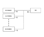
図1は、本発明の一実施形態の電力供給装置を示す。発電装置11は、例えばガスタービン発電機などの分散型の発電装置である。発電装置11の交流発電出力は、全波整流回路などのコンバータ12により整流され、コンデンサ(直流電源)13に貯留された直流電力がインバータ15により所要の周波数および電圧の交流電力に変換され、フィルタ回路16により高調波成分が除去され、出力側に接続された負荷に供給される。なお、発電装置11としては、太陽電池、燃料電池などの分散型の発電装置を用いることができる。
FIG. 1 shows a power supply apparatus according to an embodiment of the present invention. The
インバータ15は、直流電源13の直流電力から、指令値の周波数および電圧を有する交流電力を生成する電圧制御形のインバータ装置を構成しており、電力スイッチング素子をパルス幅変調信号に従ってオン/オフ制御することにより直流電力を交流電力に変換する。このため、インバータ装置(電力変換装置)は、インバータ15などの他に、出力電圧を検出する電圧検出器18、出力電流を検出する電流検出器19、出力電力を検出する電力検出器20、周波数および電圧の指令値と上記検出器18,19,20で検出されたフィードバック値に基づいて電圧指令値を演算する電圧指令演算部21、電圧制御部22、インバータ15の電力スイッチング素子をオンオフ制御するパルス幅変調信号を形成するパルス幅変調器23などの各種センサおよび制御装置を備えている。
The
電力供給装置10は、発電装置11と、該発電装置11の発電電力を所要の周波数および電圧の交流電力に変換するインバータ装置などの電力変換装置とが、ユニット化されたものである。例えば、100kWの発電能力を有する発電装置と、この発電電力を商用電源系統の周波数および電圧の交流電力に変換する電圧制御形インバータ装置などの電力変換装置とが、ユニット化され、一つの筐体(パッケージ)内に収容されたものである。従って、ユーザは、1台の電力供給装置10を備えることで、商用電源系統に接続可能な負荷に対して商用電源系統と同じ周波数および電圧の交流電力を最大100kWまで出力可能である。
The
ところが、電力供給装置のユーザの需要電力は多様であり、このため、図2に示すように、電力供給装置10を複数台並列接続し、並列運転することが行われている。例えば、同一規格の電力供給装置10をN台並列運転することで、1台当たりの出力のN倍の電力を負荷30に供給することができる。
However, the power demands of users of the power supply apparatus are various, and as a result, as shown in FIG. 2, a plurality of
ユニット化された電力供給装置10を複数台並列接続し、並列運転するに際して、各電力供給装置10の負荷分担を自動的に行うため、インバータ装置のコントローラ25は、インバータ装置の出力電流に対応する出力電圧を決定する出力電圧−出力電流制御特性を有する制御部24を備えている。この制御部24により決定された出力電圧は、指令値として電圧指令演算部21に送られる。複数台の電力供給装置10の出力端は並列接続されているので、同一の出力電流に対して同一の出力電圧を指令する制御部24を各電力供給装置10に備えることで、各電力供給装置間の負荷分担を概ね均等にすることができる。また、同一の出力電圧に対して出力電流に差を設けることで、積極的に負荷分担に差を持たせることができる。これにより、電力供給システムを構成する複数台の電力供給装置間で、専用のハードウェアによる情報の共有をしなくても、自動的に各電力供給装置間の負荷分担を概ね均等にする、あるいは、積極的に負荷分担に差を持たせることができる。
When a plurality of unitized
ところで、電圧制御形インバータ装置において、一般に、出力電圧・電流特性制御部で出力電圧指令値を決定する際に、インバータ装置の出力電流、あるいは出力電力がその定格容量の範囲内であるか否かの状態のみを考慮して出力電圧を決定している。 By the way, in a voltage controlled inverter device, in general, when the output voltage command value is determined by the output voltage / current characteristic control unit, whether or not the output current or output power of the inverter device is within the rated capacity range. The output voltage is determined in consideration of only the state.
この種の出力電圧・電流特性制御部を備えたインバータ装置を発電装置と組み合わせて電力供給装置とした場合、
発電装置の発電能力>インバータ装置の出力能力
である時は、インバータ装置の出力能力範囲内で運転するのであれば、問題が発生しない。しかしながら、運転環境により発電装置の発電能力がインバータ装置の出力能力よりも低くなった際に、すなわち、
発電装置の発電能力<インバータ装置の出力能力
である時は、インバータ装置の出力能力(通常、定格容量)となる前に発電装置が過負荷となり、安全装置が作動し、電力供給装置全体が停止してしまうという問題がある。
When an inverter device provided with this type of output voltage / current characteristic control unit is combined with a power generator to form a power supply device,
When the power generation capacity of the power generation apparatus> the output capacity of the inverter apparatus, there is no problem if the operation is performed within the output capacity range of the inverter apparatus. However, when the power generation capacity of the power generation device is lower than the output capacity of the inverter device due to the operating environment, that is,
When the power generation capacity of the power generation apparatus <the output capacity of the inverter apparatus, the power generation apparatus is overloaded before the output capacity of the inverter apparatus (usually the rated capacity) is reached, the safety device operates, and the entire power supply apparatus stops There is a problem of end up.
この問題を解決するために、本発明の電力供給装置においては、インバータ装置(電力変換装置)のコントローラ25の出力電圧・電流特性制御部24に、図3に示す出力電圧−出力電流の制御特性を持たせている。すなわち、発電装置11の発電能力を超える出力電流A(第1の出力電流)とインバータ装置の変換能力を超える出力電流B(第2の出力電流)との間(区間2)では、出力電圧−出力電流特性に第1の垂下特性を持たせ、出力電流A以下(区間1)では、出力電圧−出力電流特性に第2の垂下特性を持たせ、出力電流B以上(区間3)では、出力電圧−出力電流特性に第3の垂下特性を持たせている。
In order to solve this problem, in the power supply device of the present invention, the output voltage / current
垂下特性(出力電圧−出力電流特性)は、制御部24のメモリに予めインバータ装置の出力電流とこれに対応したインバータ装置の出力電圧のテーブルまたは関数を備え、インバータ装置の出力電流を検出し、制御部24のCPUでテーブルまたは関数を参照し、出力電圧指令値を決定することで実現できる。
The drooping characteristic (output voltage-output current characteristic) includes a table or function of the output current of the inverter device and the output voltage of the inverter device corresponding to the output current of the inverter device in advance in the memory of the
従って、図3の区間1において、発電装置11の発電能力を超える出力電流Aまでは、出力電流が大きくなると出力電圧をV0からV1まで、徐々に(緩やかに)垂下(低下)させる第2の垂下特性を持たせている。なお、図4は図3の変形例を示すものであるが、区間1において、発電装置11の発電能力を超える出力電流Aまでは、出力電流にかかわらず出力電圧を一定(V0)にする特性を持たせている。
Therefore, in the
インバータ装置の出力電流が出力電流A以上に達した場合は、区間2において、発電装置11に限界以上の負荷がかからないように、発電電力一定で出力電圧を垂下させる第1の垂下特性を持たせている。すなわち、発電装置11の出力電力を一定に制限する。そして、出力電流がさらに大きくなり、インバータ装置の変換能力を超える出力電流B以上に達した場合は、区間3において、電力変換装置に限界以上の負荷がかからないように、出力電流の増加に対して急激に出力電圧を垂下(低下)させる第3の垂下特性を持たせている。
When the output current of the inverter device reaches the output current A or more, in
図3と図4の区間2において、発電電力一定の垂下特性では、インバータ装置の出力電流と出力電圧の積が所定値以下であり、この電力供給装置を運転する場合には出力電流が増加すると出力電圧が減少し、発電装置11の発電出力は制限される。複数台の電力供給装置を並列接続する場合には、出力電圧は共通の電圧となり、出力電流はそれぞれの出力電圧−出力電流特性により決定されるので、この第1の垂下特性の区間では、電力供給装置は発電装置11の限界出力で運転され、その限界出力以上の負荷は他の電力供給装置から供給されることになる。これにより、並列運転する複数台の電力供給装置間に負荷を分散させる為の情報を共有する専用のハードウェアを設けることなく、発電装置11が過負荷となる前に他の電力供給装置へ負荷を分散できるので、電力供給装置の運転を安定して継続でき、コストと信頼性の面で大きなメリットがある。
3 and 4, in the drooping characteristics with constant generated power, the product of the output current and the output voltage of the inverter device is not more than a predetermined value, and when the power supply device is operated, the output current increases. The output voltage decreases, and the power generation output of the
例えば、発電装置11がガスタービン発電機の場合、一般的に、ガスタービン発電機の発電能力限界値は、排ガス温度(EGT)または入口空気温度の影響を強く受け、それらの温度により発電能力限界値が決まってくる。ガスタービン発電機のコントローラでは、排ガス温度または入口空気温度からガスタービン発電機の安全に運転が可能な範囲で出力可能な電力値を決定し、その値をインバータ装置を制御するコントローラ25へ伝達する。コントローラ25の出力電圧・電流特性制御部24は、上述の区間2の垂下特性として、この伝達された発電能力限界電力値に基づいて制御を行う。従って、この電力供給装置は、発電装置11の発電能力を検出する手段と、検出した発電能力に基づいて区間2の垂下特性を設定する手段とを備える。
For example, when the
上述したように、垂下特性の制御は、電流検出部19で検出した出力電流により、テーブルまたは関数としての出力電圧−出力電流特性を参照して電圧指令値を出力し、その電圧指令値からインバータ装置を制御するものである。従って、検出した発電能力に基づいて区間2の垂下特性を設定する手段は、発電装置11の発電能力限界の出力電流Aとインバータ装置の出力可能電流(定格電流)Bとから区間2の範囲を設定することができ、発電装置11の発電能力限界の出力電力から出力電圧−出力電流特性の傾きを設定することができる。
As described above, the drooping characteristic is controlled by outputting the voltage command value by referring to the output voltage-output current characteristic as a table or function based on the output current detected by the
図3と図4の区間3において、電力変換装置(インバータ装置)の変換能力を超える出力電流以上で出力電流の増加に対して出力電圧が急激に低下する垂下特性を持たせたので、電力供給装置は電力変換装置の限界出力で運転され、その限界出力以上の負荷には他の電力供給装置から電力が供給されることになる。
In
次に、図5を参照して、本発明の第1実施例について説明する。この実施例においては、図3に示す区間1に垂下特性を有する2台の電力供給装置を並列運転する場合である。発電装置の発電能力に余裕があるときは、並列運転時の電力供給装置の負荷分担率を概ね均等に保ち、発電装置の発電能力の限界に達した際は、出力電力を制限して過負荷にならないように、他の電力供給装置の分坦率が増すように制御させる。
Next, a first embodiment of the present invention will be described with reference to FIG. In this embodiment, two power supply devices having a drooping characteristic in
電力供給装置1は、無負荷時(出力電流が0)に所定の電圧(例えば、定格電圧)V0を出力する。電力供給装置2も同様に、無負荷時に所定の電圧V0を出力するが、センサ、フィルタ回路の構成部品などの誤差により、電力供給装置2から実際に出力される電圧は、V0’となり、V0とはわずか(例えば、定格電圧の0.5%程度)ではあるが相違した電圧となる。
The
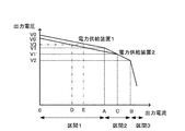
電力供給装置1は、発電装置11の発電能力の限界となる出力電流Aまでの区間1では、緩やかな垂下特性を有し、出力電流Aからインバータ装置の出力能力の限界となる出力電流Bまでの区間2では、発電装置11の発電電力一定の垂下特性を有し、出力電流B以上の区間3では、急激な垂下特性を有する。電力供給装置2は、発電装置11の発電能力の限界となる出力電流Cまでの区間1では、緩やかな垂下特性を有し、出力電流Cからインバータ装置の出力の限界となる出力電流Bまでの区間2では、発電装置11の発電電力一定の垂下特性を有し、出力電流B以上の区間3では、急激な垂下特性を有する。区間2の垂下特性により、上述のように、出力電力が所定値以下となるように制御されるので、電力供給装置の出力電力を発電装置11の発電能力の範囲内に抑えることが可能である。
The
並列運転時の2台の電力供給装置は、区間1において、出力電圧がV3であるときは、電力供給装置1は出力電流Eを分担し、電力供給装置2は出力電流Dを分担する。ここで、電力供給装置1と電力供給装置2の出力電圧差(緩やかな区間1における垂下特性の出力電圧差)が、センサ、フィルタ回路の構成部品などによる誤差程度の電圧差の場合、出力電流Eおよび出力電流Dは概ね互いに近い電流値になるので、分担を概ね均等にすることができる。電力供給装置1の出力電流が発電装置11の発電能力の限界(出力電流A)に達した際は、出力電圧−出力電流特性は区間2の垂下特性に入り、出力電力を発電能力の限界能力に制限して過負荷にならないようにし、電力供給装置2の分坦率が増すように制御される。電力供給装置2の出力電流が発電装置11の発電能力の限界(出力電流C)に達した際は、出力電圧−出力電流特性は区間2の垂下特性に入り、出力電力を発電能力の限界能力に制限して過負荷にならないように制御される。さらにインバータ装置の出力能力(定格電流)Bを超える負荷電流が要求されるときは、出力電圧−出力電流特性は区間3の垂下特性に入り、出力電圧は急速に垂下してインバータ装置が過負荷にならないように制御され、さらに並列運転している他の電力供給装置があれば、その装置から負荷へ電力が供給される。
When the output voltage of the two power supply devices in parallel operation is V3 in
なお、上記実施例では、発電装置11の発電能力に余裕があるときは、複数台の電力供給装置の負荷分担率を概ね均等に保ち、発電装置11の発電能力の限界に達した際は、出力電力を制限して過負荷にならないようにすると共に、他の電力供給装置の分坦率が増すように動作する例について説明したが、複数台の電力供給装置間で負荷の分坦率を積極的に変化させたい場合(例えば、二台運転で、一方の電力供給装置から優先的に負荷へ電力を供給させる場合)は、予め出力電圧−出力電流特性に所定の差を付けることで、出力電圧の高い方から優先的に電力を負荷へ供給できる。また、発電装置11の発電能力の限界に達した際には、電力一定になるように(限界電力値を超えないように)出力電圧を垂下させるので、電力供給装置が停止せずに、他の電力供給装置から負荷へ電力を供給させるように促すことができる。
In the above embodiment, when the power generation capacity of the
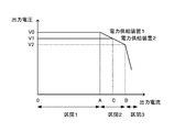
次に、図6を参照して、本発明の第2実施例について説明する。電力供給装置1は、発電装置11の発電能力の限界となる出力電流Aまでの区間1では、出力電圧一定の垂下特性を有し、インバータ装置の出力の限界となる出力電流Bまでの区間2では、発電電力を制限する垂下特性を有し、インバータ装置の出力の限界となる出力電流B以上の区間3では、出力電圧が急激に低下する垂下特性を有する。電力供給装置2は、発電装置11の発電能力の限界となる出力電流Cまでの区間1では、出力電圧一定の特性を有し、インバータ装置の出力の限界となる出力電流Bまでの区間2では、発電電力一定の垂下特性を有し、インバータ装置の出力の限界となる出力電流B以上の区間3では、出力電圧が急激に低下する垂下特性を有する。区間2の垂下特性により、上述のように、出力電力が所定値以下となるように制御される。
Next, a second embodiment of the present invention will be described with reference to FIG. The
出力電流が発電装置11の発電能力の限界により決定される出力電流Aまでの区間1において、電力供給装置1および電力供給装置2の出力電圧(指令値)を同じV0一定(実際に出力される電圧は、センサ、フィルタ回路の構成部品などの誤差により、相違した電圧)にさせ、並列運転する複数台の電力供給装置の負荷分坦率が概ね均等になるように制御する。上記区間1は、出力電圧(指令値)は一定出力だが、インバータ15自体の出力と電力供給装置全体としての出力端との間に接続されているコイルLとコンデンサCからなるフィルタ16による電圧降下が発生することにより、出力電流の増大と共に、出力端の電圧が降下し、負荷の分担率を概ね均等にすることができる。
In the
また、出力電流が発電装置11の発電能力の限界により決定される出力電流Aまでの区間1おいて、電力供給装置1および電力供給装置2の出力電圧(指令値)に差を持たせ、V0およびV1を出力電圧(指令値)にすると、出力電圧(指令値)の高い電力供給装置から優先的に電力を負荷へ供給することができる。
Further, in the
さらに負荷電流が増えて、出力電力が発電装置11の発電能力の限界(出力電流A)を超えたら、インバータ装置の出力能力の限界(出力電流B)に達するまでの区間は、発電装置11が過負荷にならない様に、一定電力(発電電力一定)制御を行い、出力電圧を低下させ、他の電力供給装置からの出力を促す。さらに負荷電流が増えて、出力電流がインバータ装置の出力能力(出力電流B)を超えたら、急激に出力電圧を低下させ(区間3)、インバータ装置が過負荷にならないようにすると共に、他の電力供給装置からの出力を促すことは、上記第1実施例と同様である。
When the load current further increases and the output power exceeds the limit of the power generation capacity (output current A) of the
なお、上記実施形態では、発電装置11のコントローラが発電装置11の発電能力限界の出力電力値を決定しているが、排ガス温度または入口空気温度の情報を電力変換装置(インバータ装置)のコントローラ25が受け取り、その値に基づいて限界発電電力値を演算し、制御に用いてもよいことは勿論である。さらに、ガスタービン発電機の例について説明したが、ガスエンジン、燃料電池、水車、太陽電池などの分散型発電装置においても、発電装置で運転環境に応じて、発電能力限界値を決定し、電力変換装置のコントローラへ伝達し、区間2の垂下特性を設定することにより、同じように利用できることも勿論である。
In the above-described embodiment, the controller of the
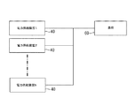
次に、本発明の他の実施形態について説明する。図7は、本発明の他の実施形態の電力供給装置を示す。発電装置41は、例えばガスタービン発電機などの分散型の発電装置である。発電装置41の交流発電出力は、全波整流回路などのコンバータ42により整流され、コンデンサ(直流電源)43に貯留された直流電力がインバータ45により所要の周波数および電圧の交流電力に変換され、フィルタ回路46により高調波成分が除去され、出力側に接続された負荷に供給される。なお、発電装置41としては、太陽電池、燃料電池などの分散型の発電装置を用いることができる。
Next, another embodiment of the present invention will be described. FIG. 7 shows a power supply apparatus according to another embodiment of the present invention. The
インバータ45は、直流電源43の直流電力から、指令値の周波数および電圧を有する交流電力を生成する電圧制御形のインバータ装置を構成しており、電力スイッチング素子をパルス幅変調信号に従ってオン/オフ制御することにより直流電力を交流電力に変換する。インバータ装置(電力変換装置)全体としては、インバータ45の出力電圧を検出する電圧検出器48a、負荷が接続された電源系統59の電圧を検出する電圧検出器48b、インバータ45の出力電流を検出する電流検出器49、出力電力を検出する電力検出器50、インバータ45の出力電流などから電圧指令値を演算する電圧指令演算部51、インバータ45の出力電圧を制御する電圧制御部52、インバータ45の出力位相を制御する位相制御部53、インバータ45の電力スイッチング素子をオンオフ制御してパルス幅変調信号を形成するパルス幅変調器54などの各種センサおよび制御装置を備えている。
The
電力供給装置40は、発電装置41と、該発電装置41の発電電力を所要の周波数および電圧の交流電力に変換するインバータ装置(電力変換装置)とが、ユニット化されたものである。例えば、100kWの発電能力を有する発電装置と、この発電電力を商用電源系統の周波数および電圧の交流電力に変換する電圧制御形インバータ装置とが、ユニット化され、一つの筐体(パッケージ)内に収容されたものである。従って、ユーザは、1台の電力供給装置40を備えることで、商用電源系統に接続可能な負荷に対して商用電源系統と同じ周波数および電圧の交流電力を最大100kWまで出力可能である。
In the
ところが、電力供給装置40に要求される需要電力は多様であり、このため、図8に示すように、電力供給装置40を複数台並列接続し、並列運転することが行われている。例えば、同一規格の電力供給装置40をN台並列運転することで、1台当たりの出力のN倍の電力を負荷60に供給することができる。
However, the demand power required for the
ユニット化された電力供給装置40を複数台並列接続し、並列運転するに際して、各電力供給装置40のインバータ装置の出力の同期を取る必要がある。このため、この電力供給装置40は、電源系統の電圧を検出する電圧検出器48bと位相制御部53を備えており、この位相制御部53により、インバータ装置の出力電圧波形(正弦波波形)の位相と、電源系統59の電圧波形の位相とを一致させる、すなわち、同期を取るようにしている。これにより、各インバータ装置間で出力電圧の位相を合わせるための同期信号を使用せずに、すべてのインバータ装置が電圧制御モードで出力を行うことができるので、出力電圧の同期を取る為の特別な信号線で各インバータ装置を接続することなく、インバータ装置の出力端を電源系統59に接続するだけで、負荷変動にも対応できる並列運転を行うことができる。
When a plurality of unitized
位相制御部53は、図9に示すように、電圧検出器48bで検出された三相電圧を、インバータ装置の内部の位相θ’に基づいてdq座標成分に変換するdq変換部61と、dq変換部61で変換されたd軸成分Vd'がゼロとなるように、インバータ装置の内部の位相θ’をフィードバック制御により調整する位相調整部62とを備えている。位相調整部62は、d軸成分Vd'を誤差位相差εとし、これをゼロとするように位相θ’を調整するPI演算部63を含む。
As shown in FIG. 9, the
電源系統59の三相電圧をインバータ装置の内部の角周波数で回転しているdq座標成分に変換することで、図10に示すように、インバータ装置の内部位相θ'(d'−q’軸)と電源系統59の三相電圧の位相θ(d−q軸)が完全に一致しているなら、電源系統59の三相電圧Vsysはq軸成分のみであるので、dq変換により得られるd軸成分Vd'はゼロとなる。また、位相差がある場合には、位相差に応じた大きさのd軸成分Vd'が演算結果として得られる。
By converting the three-phase voltage of the
すなわち、電源系統59の三相交流電圧Vu,Vv,Vwと、dq変換によるd軸成分Vdとq軸成分Vqとの位相θにおける関係は、下式のようになる。

図9に示すように、位相調整部62は、d軸成分Vd'を誤差位相差εとし、これをゼロとするように周波数補正量Δfを出力するPI演算部63と、PI演算部63の出力を制限するリミッタ64と、リミッタ64の出力をインバータ装置の出力基準周波数(例えば、50または60Hz)f*と加算する加算器65と、出力基準周波数f*と周波数補正量Δfの加算量を積分して位相θ’を出力する積分器66とを備える。位相θ’はdq変換部61にフィードバックされ、該位相θ’に基づいて系統三相電圧をdq座標成分に変換する演算が数1の式により行われる。このフィードバックループの繰り返し演算により、インバータ装置の内部位相θ’は系統電圧(電源系統59の電圧)の位相θと一致し、インバータ装置の出力電圧は系統電圧に同期したものとなる。
As shown in FIG. 9, the
積分器66から出力された位相θ’は、θ/sinθ変換器67により正弦波に変換され、電圧制御部52から出力される電圧信号と合成器68により合成され、正弦波形の出力電圧指令値として、パルス幅変調器54に供給され、インバータ装置により出力電圧波形が形成される。
The phase θ ′ output from the
しかし、図9に示す位相制御部53では、一台目の電力供給装置が起動し電力を出力している状態で、出力周波数がリミッタ64の上限値、あるいは下限値になっている(制御上発散している)場合、二台目の電力供給装置の内部位相θ’の補正が、リミッタ64の影響により行えず、電圧位相の同期を取ることができない。
However, in the
上述の問題を改善するために、図11Aに示すように位相調整部62を変更した。この位相調整部62では、誤差d軸成分Vd’がゼロにならない限りP演算器(比例制御器)63bがゼロ以外の値を出力するので、位相補正結果に揺らぎが残り、リミッタ64が補正に及ぼす影響(補正を行えなくなる現象)を改善することができる。但し、P(比例)演算器63bのゲインを大きく取りすぎると、常時残る揺らぎの影響により、出力周波数が安定しないおそれがあるので、P(比例)演算器63bのゲインは、出力に影響を及ぼさない程度の小さい値にする必要がある。
In order to improve the above problem, the
また、図11Bのように、インバータ装置の出力に影響を与えない程度の所定の外乱を外乱発生器63cにより発生させ、これをリミッタ64の出力に加算することにより、位相補正結果に強制的に揺らぎを与え、リミッタ64が補正に及ぼす影響(補正ができなくなる現象)を改善することも可能である。また、外乱を与える周期をランダムにすることにより、複数のインバータ装置間で揺らぎの周期が一致することにより生じる制御上の発散現象を防ぐことができる。
Further, as shown in FIG. 11B, a predetermined disturbance that does not affect the output of the inverter device is generated by the disturbance generator 63c, and this is added to the output of the
次に、図12および図13は、本発明のインバータ装置の動作例を示す。上述の説明は、系統電圧の位相にインバータ装置の内部位相を同期させる方法であるが、複数台の電力供給装置の並列運転において、最初に電力出力を始める電力供給装置は系統電圧を検出することができないので、上述の方法にて起動することができない。この場合は、まず、インバータ装置の内部位相回路に基準周波数(50または60Hz)を設定し、補正量Δfの演算を行わずに(Δfにゼロをセットして)基準周波数の電圧を出力する。並列運転する他の電力供給装置は、系統電圧を検出後、上述の位相同期制御(Δfによる補正)を行い、内部位相回路の補正処理を行いながら、電力出力を継続させる。 Next, FIG. 12 and FIG. 13 show an operation example of the inverter device of the present invention. The above description is a method of synchronizing the internal phase of the inverter device to the phase of the system voltage, but in the parallel operation of a plurality of power supply devices, the power supply device that starts power output first detects the system voltage. Cannot be started by the method described above. In this case, first, the reference frequency (50 or 60 Hz) is set in the internal phase circuit of the inverter device, and the voltage of the reference frequency is output without calculating the correction amount Δf (by setting zero to Δf). Other power supply apparatuses that operate in parallel perform the above-described phase synchronization control (correction by Δf) after detecting the system voltage, and continue the power output while performing the correction process of the internal phase circuit.
最初のインバータ装置が起動後、二台目以降のインバータ装置が運転を開始する際には、上述した位相同期方法により、インバータ装置の内部位相と電源系統59の検出電圧位相の同期処理を行い、同期が確立した後、並列運転を開始する。例えば、インバータ装置の内部位相と電源系統59の検出電圧位相の差が±5°以下となるまで並列運転を行わず、それ以下になると同期が確立したとして、スイッチ(K1)を閉として並列運転を開始する。
After the first inverter device is activated, when the second and subsequent inverter devices start operation, the internal phase of the inverter device and the detected voltage phase of the
上記の様に起動後、複数台のインバータ装置が並列運転中に、1台のインバータ装置が電力出力を停止する際は、インバータ装置間での制御を行っていないので、停止したい1台のインバータ装置の電力出力を停止するだけでよい。停止したインバータ装置以外のインバータ装置は、同期を維持したまま、運転を継続することができる。 After starting up as described above, when one inverter device stops power output while multiple inverter devices are operating in parallel, control between the inverter devices is not performed. It is only necessary to stop the power output of the device. Inverter devices other than the stopped inverter device can continue to operate while maintaining synchronization.
上述の様に構成することで、並列運転する複数台のインバータ装置間で情報を共有することなく、インバータ装置の出力電圧位相の同期をとることが可能となる。例えば、マイクロコンピュータを使用して、上述の同期制御を行う場合は、図14に示すような方法で行うことができる。最初に起動するインバータ装置が、単独で基準周波数の出力電圧を出力する場合には、インバータ装置の内部位相を管理するタイマ1に基準周波数1周期の時間をセットし、タイマ2に基準周波数1周期の1/360の時間をセットする。インバータ装置は、このタイマ2のタイムアップ毎にインバータ装置の出力SINテーブル(一周期分の出力データを格納、この例では、データ数は360個)参照用のポインタをインクリメントすることによって、図14の(d)に示す正弦波の出力を行う。
By configuring as described above, it is possible to synchronize the output voltage phases of the inverter devices without sharing information among a plurality of inverter devices operating in parallel. For example, when the above-described synchronization control is performed using a microcomputer, the method shown in FIG. 14 can be used. When the inverter device to be started first outputs the output voltage of the reference frequency alone, the time of the
2台目以降のインバータ装置の内部位相を、すでに起動されているインバータ装置により確立されている系統電圧の位相に同期させる際は、まず、タイマ2の初期値として、基準周波数の1/360の時間T2をセットする。次に、所定時間毎に電圧検出器により検出された三相系統電圧(図14の(a))の値を、タイマ2で管理している内部位相(ポインタ値)にてdq変換を行い、d軸成分Vd’を求める。図14の例では、dq変換演算の間隔は、1msecである。dq変換演算にて算出されたd軸成分Vd'がゼロになるようにPI演算を行い、修正量Δfが出力される。この修正量Δfを、図14(c)に示すタイマ2にセットしている値に加算(あるいは減算)して、タイマ2にセットされている基準周波数の1/360の時間を修正する(T2’をセットする)。この修正を繰り返すことにより、電源系統の電圧位相とインバータ装置の内部位相の同期を行うことができる。
When synchronizing the internal phase of the second and subsequent inverter devices with the phase of the system voltage established by the already started inverter device, first, as an initial value of the
上述したように本発明によれば、複数台のインバータ装置を並列に接続する際に、インバータ装置の出力電圧位相の同期を取る為の特別な信号線(同期線)でインバータ装置同士を接続することが不要となる。すなわち、インバータ装置の出力端子同士を並列接続するだけで、インバータ装置の出力電圧位相を同期させることができる。このため、配線量を減らすことができ、同期線の断線や親機の故障によるシステムのダウンといった問題を防止できる。また、系統電圧を利用して電圧制御モードで運転するインバータ装置の同期を取れるので、異機種・異形式のインバータ装置間でも容易に並列同期運転を行える上、系統電圧の周波数が、リミッタのリミット値と一致する場合においても、同期を取ることができる。 As described above, according to the present invention, when a plurality of inverter devices are connected in parallel, the inverter devices are connected by a special signal line (synchronization line) for synchronizing the output voltage phases of the inverter devices. Is no longer necessary. That is, the output voltage phase of the inverter device can be synchronized only by connecting the output terminals of the inverter device in parallel. For this reason, the amount of wiring can be reduced, and problems such as disconnection of the synchronization line and system down due to a failure of the master unit can be prevented. In addition, since the inverter device that operates in the voltage control mode using the system voltage can be synchronized, parallel synchronous operation can be easily performed between different types and types of inverter devices, and the frequency of the system voltage is limited by the limiter. Even when the values match, synchronization can be achieved.
さらに、dq変換部61や位相調整部62はマイクロプロセサで容易に構成できるので、ハード的には既存のマイクロプロセサや電圧検出器等を利用でき、新規なハードウェアを必要とせず、低コストなシステムとすることができる。
Furthermore, since the
なお、上記実施形態では、分散形発電装置とインバータ装置などの電力変換装置とをユニット化した電力供給装置を複数台並列運転する例について説明してきたが、例えば共通の直流電源を用い、複数台のインバータ装置を並列運転する際にも、上記方法を同様に利用可能である。 In the above embodiment, an example has been described in which a plurality of power supply devices in which a distributed power generator and a power converter such as an inverter are unitized are operated in parallel. The above method can be used in the same manner when the inverter devices are operated in parallel.
ここで、これまで本発明の一実施形態について説明したが、本発明は上述の実施形態に限定されず、その技術的思想の範囲内において種々異なる形態にて実施されてよいことは勿論である。 Here, one embodiment of the present invention has been described so far. However, the present invention is not limited to the above-described embodiment, and may of course be implemented in various forms within the scope of the technical idea. .
10 電力供給装置
11 発電装置
12 コンバータ
13 直流電源
15,45 インバータ
16 フィルタ回路
18a,18b 電圧検出器
19 電流検出器
20 電力検出器
21 電圧指令演算部
22 電圧制御部
23,54 パルス幅変調器
24 出力電圧−出力電流特性制御部
30,60 負荷
53 位相制御部
59 電源系統
61 dq変換部
62 位相調整部
63 PI演算部
63b P演算器
64 リミッタ
65 加算器
66 積分器
67 変換器
68 合成器
DESCRIPTION OF
Claims (12)
該発電装置の発電電力を所要の周波数および電圧の交流電力に変換する電力変換装置と、
前記電力変換装置のコントローラとを備えた電力供給装置であって、
前記コントローラは、前記電力変換装置の出力電流に対応する出力電圧を決定する出力電圧−出力電流特性の制御部を備え、
前記出力電圧−出力電流特性に、前記発電装置の発電能力を超える第1の出力電流と、前記電力変換装置の変換能力を超える第2の出力電流との間では、前記発電装置の出力電力を制限する第1の垂下特性を持たせたことを特徴とする電力供給装置。 A power generator,
A power conversion device that converts the generated power of the power generation device into AC power having a required frequency and voltage;
A power supply device comprising a controller of the power conversion device,
The controller includes an output voltage-output current characteristic control unit that determines an output voltage corresponding to an output current of the power converter,
In the output voltage-output current characteristic, the output power of the power generation device is between the first output current exceeding the power generation capability of the power generation device and the second output current exceeding the conversion capability of the power conversion device. A power supply device having a first drooping characteristic to be limited.
前記電力変換装置が並列接続される電源系統の三相電圧を検出し、
前記三相電圧を、前記電力変換装置内部の位相θ’に基づいてdq座標に変換し、d軸成分Vd'を検出し、
前記d軸成分Vd'がゼロとなるようにPI制御を行い、内部位相の補正量Δfを出力し、該補正量Δfを、電力変換装置の出力基準周波数f*に加算するとともに、所定のゆらぎ周波数を補正量Δfに加算し、位相θ’を前記系統の電圧位相θと一致させ、
前記位相θ’に基づいて前記電力変換装置が正弦波交流電圧を形成し、前記電源系統の交流電圧と同期を取ることを特徴とする電力変換装置の同期運転方法。 A method of synchronously operating a power converter in a system that connects a plurality of power converters in parallel and supplies three-phase AC power to a load,
Detecting a three-phase voltage of a power system to which the power converter is connected in parallel;
Converting the three-phase voltage into a dq coordinate based on a phase θ ′ inside the power converter, and detecting a d-axis component Vd ′;
PI control is performed so that the d-axis component Vd ′ becomes zero, an internal phase correction amount Δf is output, the correction amount Δf is added to the output reference frequency f * of the power converter, and a predetermined fluctuation occurs. The frequency is added to the correction amount Δf, and the phase θ ′ is matched with the voltage phase θ of the system,
A method for synchronous operation of a power converter, wherein the power converter forms a sine wave AC voltage based on the phase θ ′ and synchronizes with the AC voltage of the power supply system.
前記電力変換装置が並列接続される電源系統の三相電圧を検出する電圧検出器と、
前記電圧検出器で検出された三相電圧を、前記電力変換装置内部の位相θ’に基づいてdq座標に変換し、d軸成分Vd'を検出する演算部と、
前記d軸成分Vd'を誤差位相差εとし、これをゼロとするように周波数補正量Δfを出力するPI演算部と、
該PI演算部の出力を制限するリミッタと、
所定のゆらぎ周波数を発生させるゆらぎ周波数発生器と、
前記リミッタの出力と前記電力変換装置の出力基準周波数f*と前記ゆらぎ周波数発生器の出力とを加算する加算器と、
前記加算器の出力を積分して位相θ’を出力する積分器とを備え、
前記系統の電圧位相θと一致させた位相θ’に基づいて、前記系統の交流電圧と同期した正弦波交流電圧を出力することを特徴とする電力変換装置。 A power conversion device used in a power supply system for connecting a plurality of power conversion devices in parallel and supplying three-phase AC power to a load,
A voltage detector for detecting a three-phase voltage of a power supply system to which the power converter is connected in parallel;
A calculation unit that converts the three-phase voltage detected by the voltage detector into a dq coordinate based on a phase θ ′ inside the power converter and detects a d-axis component Vd ′;
A PI calculation unit that outputs the frequency correction amount Δf so that the d-axis component Vd ′ is set to an error phase difference ε and zero;
A limiter for limiting the output of the PI calculation unit;
A fluctuation frequency generator for generating a predetermined fluctuation frequency;
An adder for adding the output of the limiter, the output reference frequency f * of the power converter, and the output of the fluctuation frequency generator;
An integrator that integrates the output of the adder and outputs a phase θ ′;
A power converter that outputs a sinusoidal AC voltage synchronized with an AC voltage of the system based on a phase θ ′ that is matched with the voltage phase θ of the system.
前記電力変換装置が並列接続される電源系統の三相電圧を検出する電圧検出器と、
前記電力変換装置を、前記電源系統に接続するスイッチとを備え、
前記電圧検出器で前記電源系統の三相電圧が検出されない場合は、前記スイッチを閉じて前記電力変換装置から基準周波数の交流電圧を出力させ、
前記電圧検出器で前記電源系統の電圧が検出された場合には、前記電力変換装置の電圧位相を前記電源系統の三相電圧の位相と一致するように位相調整を行い、前記電源系統の三相電圧との位相差が所定値以内となった場合に、前記スイッチを閉じることを特徴とする電力変換装置。 A power conversion device used in a power supply system for connecting a plurality of power conversion devices in parallel and supplying three-phase AC power to a load,
A voltage detector for detecting a three-phase voltage of a power supply system to which the power converter is connected in parallel;
A switch for connecting the power conversion device to the power supply system;
When the three-phase voltage of the power system is not detected by the voltage detector, the switch is closed and the AC voltage of the reference frequency is output from the power converter,
When the voltage detector detects the voltage of the power supply system, the voltage phase of the power converter is adjusted so as to match the phase of the three-phase voltage of the power supply system, A power converter characterized by closing the switch when a phase difference with a phase voltage falls within a predetermined value.
Priority Applications (1)
| Application Number | Priority Date | Filing Date | Title |
|---|---|---|---|
| JP2007138054A JP2008043184A (en) | 2006-05-25 | 2007-05-24 | Power supply unit, and method for synchronously operating power conversion device |
Applications Claiming Priority (3)
| Application Number | Priority Date | Filing Date | Title |
|---|---|---|---|
| JP2006145536 | 2006-05-25 | ||
| JP2006194605 | 2006-07-14 | ||
| JP2007138054A JP2008043184A (en) | 2006-05-25 | 2007-05-24 | Power supply unit, and method for synchronously operating power conversion device |
Publications (1)
| Publication Number | Publication Date |
|---|---|
| JP2008043184A true JP2008043184A (en) | 2008-02-21 |
Family
ID=39177563
Family Applications (1)
| Application Number | Title | Priority Date | Filing Date |
|---|---|---|---|
| JP2007138054A Pending JP2008043184A (en) | 2006-05-25 | 2007-05-24 | Power supply unit, and method for synchronously operating power conversion device |
Country Status (1)
| Country | Link |
|---|---|
| JP (1) | JP2008043184A (en) |
Cited By (15)
| Publication number | Priority date | Publication date | Assignee | Title |
|---|---|---|---|---|
| JP2011114948A (en) * | 2009-11-26 | 2011-06-09 | Fuji Electric Systems Co Ltd | Self-sustained restoring system of linked inverter |
| CN102104254A (en) * | 2009-12-18 | 2011-06-22 | 东芝三菱电机产业系统株式会社 | Land power source device for ship |
| JP2011244537A (en) * | 2010-05-14 | 2011-12-01 | Fuji Electric Co Ltd | Controller of power converter |
| JP2013055747A (en) * | 2011-09-01 | 2013-03-21 | Yaskawa Electric Corp | Power conversion device |
| JP2014054036A (en) * | 2012-09-06 | 2014-03-20 | Toyo Electric Mfg Co Ltd | Wind force power generation device |
| JP2015032297A (en) * | 2013-08-07 | 2015-02-16 | 株式会社ダイヘン | Control circuit controlling power conversion circuit, power conversion device including the control circuit, electric power system including the power conversion device, and control method |
| JP2015104292A (en) * | 2013-11-28 | 2015-06-04 | 株式会社明電舎 | Synchronous control circuit of ac-dc conversion device |
| KR101529586B1 (en) * | 2013-08-02 | 2015-06-29 | 엘에스산전 주식회사 | Method for controlling three-phase inverter output |
| JP2016515375A (en) * | 2013-03-14 | 2016-05-26 | エスエムエイ ソーラー テクノロジー アクティエンゲゼルシャフトSMA Solar Technology AG | Method for automatically starting a power plant comprising a plurality of inverters connectable to an AC electric grid |
| JP2017005930A (en) * | 2015-06-12 | 2017-01-05 | パナソニックIpマネジメント株式会社 | Power storage system, power storage device and operation method for power storage device |
| JP2018023239A (en) * | 2016-08-05 | 2018-02-08 | 東芝三菱電機産業システム株式会社 | Power conversion device |
| JP2018148705A (en) * | 2017-03-06 | 2018-09-20 | ダイキン工業株式会社 | Electric power conversion system and motor drive system |
| JP2018170863A (en) * | 2017-03-30 | 2018-11-01 | 本田技研工業株式会社 | Generator system |
| US10247764B2 (en) | 2013-07-25 | 2019-04-02 | Daihen Corporation | Method for controlling devices provided with communication function, and device used in implementing the method |
| WO2020013015A1 (en) * | 2018-07-09 | 2020-01-16 | 日立三菱水力株式会社 | Variable-speed generator-motor device |
Citations (5)
| Publication number | Priority date | Publication date | Assignee | Title |
|---|---|---|---|---|
| JPS5765226A (en) * | 1980-10-04 | 1982-04-20 | Meidensha Electric Mfg Co Ltd | Inverter parallel operation system |
| JPH0496635A (en) * | 1990-08-13 | 1992-03-30 | Toshiba Corp | Parallel operation apparatus of uninterruptible power supplies(ups) |
| JPH0583862A (en) * | 1991-09-18 | 1993-04-02 | Toshiba Corp | Power converter |
| JP2000080928A (en) * | 1998-09-03 | 2000-03-21 | Toyota Motor Corp | Gas turbine output control device |
| JP2003102200A (en) * | 2001-07-19 | 2003-04-04 | Yamaha Motor Co Ltd | Inverter system generator |
-
2007
- 2007-05-24 JP JP2007138054A patent/JP2008043184A/en active Pending
Patent Citations (5)
| Publication number | Priority date | Publication date | Assignee | Title |
|---|---|---|---|---|
| JPS5765226A (en) * | 1980-10-04 | 1982-04-20 | Meidensha Electric Mfg Co Ltd | Inverter parallel operation system |
| JPH0496635A (en) * | 1990-08-13 | 1992-03-30 | Toshiba Corp | Parallel operation apparatus of uninterruptible power supplies(ups) |
| JPH0583862A (en) * | 1991-09-18 | 1993-04-02 | Toshiba Corp | Power converter |
| JP2000080928A (en) * | 1998-09-03 | 2000-03-21 | Toyota Motor Corp | Gas turbine output control device |
| JP2003102200A (en) * | 2001-07-19 | 2003-04-04 | Yamaha Motor Co Ltd | Inverter system generator |
Cited By (19)
| Publication number | Priority date | Publication date | Assignee | Title |
|---|---|---|---|---|
| JP2011114948A (en) * | 2009-11-26 | 2011-06-09 | Fuji Electric Systems Co Ltd | Self-sustained restoring system of linked inverter |
| CN102104254A (en) * | 2009-12-18 | 2011-06-22 | 东芝三菱电机产业系统株式会社 | Land power source device for ship |
| JP2011244537A (en) * | 2010-05-14 | 2011-12-01 | Fuji Electric Co Ltd | Controller of power converter |
| JP2013055747A (en) * | 2011-09-01 | 2013-03-21 | Yaskawa Electric Corp | Power conversion device |
| US8670257B2 (en) | 2011-09-01 | 2014-03-11 | Kabushiki Kaisha Yaskawa Denki | Power conversion apparatus |
| JP2014054036A (en) * | 2012-09-06 | 2014-03-20 | Toyo Electric Mfg Co Ltd | Wind force power generation device |
| JP2016515375A (en) * | 2013-03-14 | 2016-05-26 | エスエムエイ ソーラー テクノロジー アクティエンゲゼルシャフトSMA Solar Technology AG | Method for automatically starting a power plant comprising a plurality of inverters connectable to an AC electric grid |
| US10247764B2 (en) | 2013-07-25 | 2019-04-02 | Daihen Corporation | Method for controlling devices provided with communication function, and device used in implementing the method |
| US11624760B2 (en) | 2013-07-25 | 2023-04-11 | Daihen Corporation | Method for controlling devices provided with communication function, and device used in implementing the method |
| US11029345B2 (en) | 2013-07-25 | 2021-06-08 | Daihen Corporation | Method for controlling devices provided with communication function, and device used in implementing the method |
| KR101529586B1 (en) * | 2013-08-02 | 2015-06-29 | 엘에스산전 주식회사 | Method for controlling three-phase inverter output |
| JP2015032297A (en) * | 2013-08-07 | 2015-02-16 | 株式会社ダイヘン | Control circuit controlling power conversion circuit, power conversion device including the control circuit, electric power system including the power conversion device, and control method |
| JP2015104292A (en) * | 2013-11-28 | 2015-06-04 | 株式会社明電舎 | Synchronous control circuit of ac-dc conversion device |
| JP2017005930A (en) * | 2015-06-12 | 2017-01-05 | パナソニックIpマネジメント株式会社 | Power storage system, power storage device and operation method for power storage device |
| JP2018023239A (en) * | 2016-08-05 | 2018-02-08 | 東芝三菱電機産業システム株式会社 | Power conversion device |
| JP2018148705A (en) * | 2017-03-06 | 2018-09-20 | ダイキン工業株式会社 | Electric power conversion system and motor drive system |
| JP2018170863A (en) * | 2017-03-30 | 2018-11-01 | 本田技研工業株式会社 | Generator system |
| WO2020013015A1 (en) * | 2018-07-09 | 2020-01-16 | 日立三菱水力株式会社 | Variable-speed generator-motor device |
| JPWO2020013015A1 (en) * | 2018-07-09 | 2021-05-20 | 日立三菱水力株式会社 | Variable speed generator motor |
Similar Documents
| Publication | Publication Date | Title |
|---|---|---|
| JP2008043184A (en) | Power supply unit, and method for synchronously operating power conversion device | |
| EP1860750A2 (en) | Electric power supply apparatus and method of synchronously operating power converter | |
| JP4846450B2 (en) | Inverter power controller | |
| JP6398414B2 (en) | Power storage system, power conversion device, self-sustaining operation system, and power storage system control method | |
| JP5508796B2 (en) | Power supply system control method and power supply system control apparatus | |
| JP2004532595A (en) | How to operate a wind turbine | |
| US9548690B2 (en) | System and method for adjusting current regulator gains applied within a power generation system | |
| JP2009225599A (en) | Power converter | |
| JP2007037276A (en) | Generator using ac exciting synchronous generator and control method thereof | |
| JP2008061356A (en) | Islanding operation detedctor and detection method, power conditioner incorporating islanding operation detector | |
| US10030632B2 (en) | Control device for voltage source converter and operating method thereof | |
| US9531191B2 (en) | Method and apparatus for power imbalance correction in a multi-phase power generator | |
| JP6011739B1 (en) | Control device and power conversion system | |
| CN101098079A (en) | Electric power supply apparatus and method of synchronously operating power converter | |
| JP5398233B2 (en) | Independent operation detection device for inverter and isolated operation detection method | |
| JP6159271B2 (en) | Power converter and control method of power converter | |
| US10811881B1 (en) | Method and system for regulating an electrical converter for autonomous frequency stabilization with load transients in a micro-network comprising a diesel generating set | |
| CN113574781A (en) | Inverter control device and method | |
| US11527966B2 (en) | Power conversion apparatus that judges system power failure based on system frequency and voltage | |
| JP2016167926A (en) | Power fluctuation suppressing device | |
| JP2008141815A (en) | Uninterruptible power supply system | |
| JP6161985B2 (en) | Isolated operation detection circuit, isolated operation detection method, inverter device provided with the isolated operation detection circuit, and power system | |
| KR20090100704A (en) | Inverter for solar power generating system | |
| WO2023112222A1 (en) | Electric power conversion device and control method for electric power conversion device | |
| WO2013111172A1 (en) | Conversion device for secondary excitation wind-powered electricity generation, control device for secondary excitation wind-powered electricity generation, and method for controlling conversion device for secondary excitation wind-powered electricity generation |
Legal Events
| Date | Code | Title | Description |
|---|---|---|---|
| A621 | Written request for application examination |
Free format text: JAPANESE INTERMEDIATE CODE: A621 Effective date: 20100506 |
|
| A977 | Report on retrieval |
Free format text: JAPANESE INTERMEDIATE CODE: A971007 Effective date: 20120521 |
|
| A131 | Notification of reasons for refusal |
Free format text: JAPANESE INTERMEDIATE CODE: A131 Effective date: 20120529 |
|
| A521 | Written amendment |
Free format text: JAPANESE INTERMEDIATE CODE: A523 Effective date: 20120727 |
|
| A131 | Notification of reasons for refusal |
Free format text: JAPANESE INTERMEDIATE CODE: A131 Effective date: 20120918 |
|
| A02 | Decision of refusal |
Free format text: JAPANESE INTERMEDIATE CODE: A02 Effective date: 20130205 |