JP2007509529A - Method for correcting dynamic nulls in power line communication systems - Google Patents
Method for correcting dynamic nulls in power line communication systems Download PDFInfo
- Publication number
- JP2007509529A JP2007509529A JP2006535336A JP2006535336A JP2007509529A JP 2007509529 A JP2007509529 A JP 2007509529A JP 2006535336 A JP2006535336 A JP 2006535336A JP 2006535336 A JP2006535336 A JP 2006535336A JP 2007509529 A JP2007509529 A JP 2007509529A
- Authority
- JP
- Japan
- Prior art keywords
- communication
- complex impedance
- quality
- power network
- processor
- Prior art date
- Legal status (The legal status is an assumption and is not a legal conclusion. Google has not performed a legal analysis and makes no representation as to the accuracy of the status listed.)
- Withdrawn
Links
Images

Classifications
-
- H—ELECTRICITY
- H04—ELECTRIC COMMUNICATION TECHNIQUE
- H04B—TRANSMISSION
- H04B3/00—Line transmission systems
- H04B3/54—Systems for transmission via power distribution lines
-
- H—ELECTRICITY
- H04—ELECTRIC COMMUNICATION TECHNIQUE
- H04B—TRANSMISSION
- H04B2203/00—Indexing scheme relating to line transmission systems
- H04B2203/54—Aspects of powerline communications not already covered by H04B3/54 and its subgroups
- H04B2203/5404—Methods of transmitting or receiving signals via power distribution lines
- H04B2203/5425—Methods of transmitting or receiving signals via power distribution lines improving S/N by matching impedance, noise reduction, gain control
Landscapes
- Engineering & Computer Science (AREA)
- Power Engineering (AREA)
- Computer Networks & Wireless Communication (AREA)
- Signal Processing (AREA)
- Cable Transmission Systems, Equalization Of Radio And Reduction Of Echo (AREA)
- Transmitters (AREA)
Abstract
【課題】複素インピーダンスを有する電力網内での通信を可能にする方法を提供する。
【解決手段】本方法は、複素インピーダンスを変更する段階と、この変更する段階が通信の品質に影響を与えたか否かを判定する段階とを含む。別の態様では、本方法は、電力網内での通信の品質を判定する段階と、品質が許容閾値以下である場合に複素インピーダンスを変更する段階とを含む。さらに別の態様では、本方法は、電力網を介して情報を送信する段階と、複素インピーダンスを変更する段階と、電力網を介して情報を再送信する段階とを含む。
【選択図】 図1
A method is provided for enabling communication within a power network having complex impedance.
The method includes changing a complex impedance and determining whether the changing step has affected communication quality. In another aspect, the method includes determining the quality of communication within the power network and changing the complex impedance if the quality is below an acceptable threshold. In yet another aspect, the method includes transmitting information over the power network, changing the complex impedance, and retransmitting the information over the power network.
[Selection] Figure 1
Description
本開示は、電力線通信に関し、より具体的には、電力線通信システム内でのヌル周波数を処理する方法に関する。 The present disclosure relates to power line communication, and more specifically to a method for handling null frequencies in a power line communication system.
電力線通信(PLC)システムでは、通信信号は、電力網の電線を通して伝播する。PLCの信号伝達は一般的に、電力線電圧の上に、例えば20KHzよりも高い周波数の高周波信号を重畳させることによって実行される。電力網内の電気コンセントは、電源及び通信信号用ポートの両方としての役割を果たすことができる。従って、電気コンセントに差し込まれたPLCトランシーバは、電気コンセントを介して電力及び通信信号の両方を受ける。しかしながら、幾つかのPLCデバイスは、電力線から電力を受ける必要がないか、又は少なくとも電力線からの電力に依存しないことに注目されたい。従って、PLCシステムでは、電力線は、通信目的のために使用され、幾つかのケースでは、電力が存在する時か又は存在しない時のどちらでも通信を行うことができる。 In power line communication (PLC) systems, communication signals propagate through power grid wires. PLC signal transmission is generally performed by superimposing a high-frequency signal having a frequency higher than, for example, 20 KHz on the power line voltage. An electrical outlet in the power grid can serve as both a power source and a communication signal port. Thus, a PLC transceiver plugged into an electrical outlet receives both power and communication signals through the electrical outlet. It should be noted, however, that some PLC devices do not need to receive power from the power line, or at least do not rely on power from the power line. Thus, in PLC systems, power lines are used for communication purposes, and in some cases, communication can occur either when power is present or not present.
ヌル(null)は、その周波数において通信信号が望ましくないレベルまで減弱された周波数である。通信周波数は、定常波の相殺的干渉によって引き起こされるヌルの影響を受けやすい。ディープ(深い)ヌル(deep null)がPLCシステムの搬送周波数で発生した場合には、通信が、機能しなくなる可能性がある。 Null is a frequency at which the communication signal is attenuated to an undesirable level. The communication frequency is susceptible to nulls caused by standing wave destructive interference. If deep null occurs at the carrier frequency of the PLC system, communication may not work.
ヌル信号が発生する周波数は、電力網の複素インピーダンスの関数である。複素インピーダンスもまた、電力網に結合された電気デバイス又は電気器具の存在によって影響を受ける。複素インピーダンスはさらに、変化する周波数においてその各々が反射を引き起こしてインピーダンスに影響を与える可能性がある多数の分岐配線回路によって影響を受ける。 The frequency at which the null signal is generated is a function of the complex impedance of the power network. Complex impedance is also affected by the presence of electrical devices or appliances coupled to the power grid. The complex impedance is further affected by a number of branch wiring circuits, each of which can cause reflections at varying frequencies to affect the impedance.
PLCシステムは、住宅又は商用ビルのような単一の構造物内において又はそのような構造物の総合施設全体にわたって実施することができる。従って、PLCシステムは、いずれかの特定の地理的場所、規模又は接続形態に本質的に限定されず、PLCシステムは、構造物間の電気配線を含むことができる。 The PLC system can be implemented in a single structure, such as a residential or commercial building, or across an entire facility of such a structure. Thus, the PLC system is not essentially limited to any particular geographic location, scale, or topology, and the PLC system can include electrical wiring between structures.
複素インピーダンスはまた、電力網に結合された電気デバイス又は電気器具の作動によって影響を受ける。例えば、電灯の点灯は、複素インピーダンスの変化、従ってヌルの変化を引き起こす可能性がある。その結果、ヌルのデプス(深さ)及び/又は周波数が変化することになる。 Complex impedance is also affected by the operation of electrical devices or appliances coupled to the power grid. For example, lighting a light can cause a complex impedance change, and thus a null change. As a result, null depth (depth) and / or frequency will change.
幾つかのPLCデバイスは、極端な狭帯域のデバイスである。米国特許第6,441,723号には、非常に狭い帯域幅の単一周波数を使用するデバイスが記載されている。その結果、ヌルが単一周波数で発生した場合には、デバイスは、作動不能となるおそれがある。 Some PLC devices are extremely narrow band devices. US Pat. No. 6,441,723 describes a device that uses a single frequency with a very narrow bandwidth. As a result, if nulls occur at a single frequency, the device may become inoperable.
幾つかの方法が、ヌルに起因する問題を回避する試みにおいて使用されてきた。第1の方法は、PLC信号が定常波によって影響を受けないように、比較的低い周波数、従って比較的長い波長を有するPLC信号を使用することである。より低い周波数に基づいたデバイスは、多くの問題を提示する。第1に、電力線の1つの位相から他の位相に効果的に通信するためには、デバイスは一般的に、位相間で信号を結合する「位相ブリッジ」の設置を必要とする。このことは、位相ブリッジが住宅所有者によって常に容易に設置されるとはかぎらないので、設置コストと複雑さを著しく高める。第2に、より低い周波数においては電気器具から非常に多くのノイズが発生し、従って信号の品質に影響する信号対ノイズ比を低下させる。第3に、テレビジョンに通常存在するような電気器具内のコンデンサは、干渉を低減するように設計されてきたが、同時に所望の通信信号を著しく減弱させる可能性もある。第2の方法は、PLC信号として使用可能な複数の周波数を有することであり、第1の周波数で通信が不満足な場合には、次に第2の周波数に切り替える。この第2の方法は、複数の周波数の全てにおいて作動可能であるPLCデバイスを必要とし、それに加えて、デバイスを適切な周波数に調整するための制御プロトコルを必要とする。その結果、単一周波数を使用するシステムと比較すると、この第2の方法は、付加的なハードウエアと、比較的複雑な制御プロトコルとを必要とする。第3の方法は、狭いヌルがPLC信号の小部分だけを減弱させるが、それでもPLC信号の他の部分が生き残って満足な通信をもたらすようなスペクトル拡散法を使用する。この第3の方法は、特定の周波数ヌルによって変更されたスペクトル拡散信号を適切に受信するための整合フィルタ又は他の特殊な受信ハードウエアの使用を必要とする。その結果、単一周波数を使用するシステムと比較すると、この第3の方法は、付加的な受信機ハードウエア及び/又はソフトウエアを必要とする。
単一周波数システムは、それがより少ない部品を有するが故に、アジャイル周波数システムと比較すると一般的に廉価であり、設計が複雑でなく、かつより信頼性が高いので、単一周波数を使用する通信システムを維持することが望ましい。従って、単一周波数の電力線通信デバイスの作動を妨害するヌルを処理するための方法の改良に対する必要性が存在する。 Single frequency systems are generally less expensive compared to agile frequency systems because they have fewer components, are less complex in design, and are more reliable, so communication using a single frequency It is desirable to maintain the system. Accordingly, there is a need for improved methods for handling nulls that interfere with the operation of single frequency power line communication devices.
複素インピーダンスを有する電力網内での通信を可能にする方法を提供する。1つの態様では、本方法は、複素インピーダンスを変更する段階と、変更する段階が通信の品質に影響を与えたか否かを判定する段階とを含む。別の態様では、本方法は、電力網内での通信の品質を判定する段階と、品質が許容閾値以下である場合に複素インピーダンスを変更する段階とを含む。さらに別の態様では、本方法は、電力網を介して情報を送信する段階と、複素インピーダンスを変更する段階と、電力網を介して情報を再送信する段階とを含む。 A method is provided for enabling communication within a power network having a complex impedance. In one aspect, the method includes changing the complex impedance and determining whether the changing has affected communication quality. In another aspect, the method includes determining the quality of communication within the power network and changing the complex impedance if the quality is below an acceptable threshold. In yet another aspect, the method includes transmitting information over the power network, changing the complex impedance, and retransmitting the information over the power network.
本発明の実施形態は、複素インピーダンスを有する電力網内での通信を可能にするための装置である。本装置は、複素インピーダンスを変更するための回路と、変更が通信の品質に影響を与えたか否かを判定するためのプロセッサとを含む。 An embodiment of the present invention is an apparatus for enabling communication within a power network having a complex impedance. The apparatus includes a circuit for changing the complex impedance and a processor for determining whether the change has affected the quality of communication.
本発明の別の実施形態は、複素インピーダンスを有する電力網内での通信を可能にするためのプロセッサである。1つの態様では、本プロセッサは、電力網内での通信の品質を判定するためのモジュールと、品質が許容閾値以下である場合に複素インピーダンスを変更するように回路を制御するためのモジュールとを含む。別の態様では、本プロセッサは、電力網を介して情報を送信するように送信機に通知するためのモジュールと、複素インピーダンスを変更するように回路を制御するためのモジュールと、情報を再送信するように送信機に通知するためのモジュールとを含む。 Another embodiment of the invention is a processor for enabling communication within a power network having a complex impedance. In one aspect, the processor includes a module for determining a quality of communication within the power network and a module for controlling the circuit to change the complex impedance when the quality is below an acceptable threshold. . In another aspect, the processor retransmits information, a module for notifying a transmitter to transmit information over a power network, a module for controlling a circuit to change complex impedance, and And a module for notifying the transmitter.
本発明のさらに別の実施形態は、複素インピーダンスを有する電力網内での通信を可能にするプロセッサを制御するための命令を含む記憶媒体である。1つの態様では、本記憶媒体は、プロセッサを制御して電力網内での通信の品質を判定するための命令と、品質が許容閾値以下である場合にプロセッサを制御して複素インピーダンスを変更するように回路を制御するための命令とを含む。別の態様では、本記憶媒体は、プロセッサを制御して電力網を介して情報を送信するように送信機に通知するための命令と、プロセッサを制御して複素インピーダンスを変更するように回路を制御するための命令と、プロセッサを制御して情報を再送信するように送信機に通知するための命令とを含む。 Yet another embodiment of the invention is a storage medium that includes instructions for controlling a processor that enables communication within a power network having a complex impedance. In one aspect, the storage medium controls the processor to determine the quality of communication within the power network and controls the processor to change the complex impedance when the quality is below an acceptable threshold. And instructions for controlling the circuit. In another aspect, the storage medium controls instructions to control the processor to notify the transmitter to transmit information over the power network and to control the processor to change the complex impedance. And instructions for notifying the transmitter to control the processor and retransmit the information.
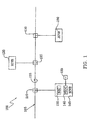
図1は、例えば60ヘルツ(Hz)120ボルトの交流電流(V.AC)電力網のような電力網105内に実装されたPLCシステム100の概略線図である。電力網105は、電力線115と、複数の電気コンセント110、125及び130とを含む。電力線115は、単一線として図示しているが、実際には、電力線115は通常、単一回路上に多数の配線分岐部を備えた例えばホットライン、ニュートラルライン及びアースラインのような複数の導線を含む。PLCシステム100は、3つのトランシーバ145、120及び150を含み、これらのトランシーバは、それぞれ電気コンセント110、125及び130を介して電力網105に接続される。
FIG. 1 is a schematic diagram of a
トランシーバ145、120及び150の各々は、その中に一体化された送信機及び受信機を有し、そのどちらも図1には明確に示していない。送信機及び受信機を保有することによって、トランシーバ145、120及び150が、互いに双方向に通信することが可能になる。トランシーバ145、120及び150は各々、通信プロトコルに従って通信を行うマスタデバイス又はスレーブデバイスとして構成することができる。PLCシステム100は、あらゆる数のトランシーバを含むことができ、またPLCシステム100は、別個の送信機又は別個の受信機を含むこともできる。
Each of the
トランシーバ145がトランシーバ120と通信したいと望むと仮定する。従って、トランシーバ145は、コンセント110を介して信号を送信する。信号は、電力線115を通して伝播し、トランシーバ120が、コンセント125を介して信号を受信する。従って、トランシーバ145は、送信の開始者であり、トランシーバ120は、送信の対象である。多くの通信プロトコルでは、トランシーバ120は、信号の受信に応答して電力線115を通して肯定応答信号をトランシーバ145に送信する。トランシーバ145が肯定応答信号を受信すると、トランシーバ145は、トランシーバ120との通信が成功したと判定する。
Assume that
通信信号周波数、特に1メガヘルツ(MHz)以上の周波数は、複素インピーダンス、すなわち電力網105の抵抗、キャパシタンス及びインダクダンスの集合作用によって引き起こされる悪影響を受け易い。また、複素インピーダンスの影響は、電力網105の異なる部分において異なる可能性がある。
Communication signal frequencies, particularly frequencies above 1 megahertz (MHz), are susceptible to adverse effects caused by the complex impedance, that is, the collective action of the
例えば、トランシーバ145が信号、すなわち送信信号を13.56MHzの周波数で送信すると仮定する。送信信号は、電力網105を通して伝播することになり、トランシーバ120によって満足に受信されることになるが、それでも送信信号はまた、コンセント130において著しく、すなわち−70デシベル(db)減弱され、その結果、トランシーバ150によって受信されない場合がある。コンセント130におけるそのような減弱は、2つ又はそれ以上の信号の相殺的打消しによるものである。これらの打消し信号のうち、1つは、コンセント110からコンセント130への送信信号である。他の信号、すなわち干渉信号は、電力網105内の他の電気経路からの反射である。電力網105は60Hzの電流に対して設計されているので、13.56MHzの信号は、配線分岐部が終端するか又は電気器具に接続される位置から反射されることになる。信号は、電力網105全体にわたって分布した様々なインダクタンス、抵抗及びキャパシタンス値、すなわち複素インピーダンスに起因して異なる量の位相シフトを受けることになる。信号の位相及び振幅がコンセント130において送信信号を打ち消すような状態で組合さった場合には、送信信号は著しく減弱される。
For example, assume that
従って、特定の打消しバランスの場合には、減弱は大きくなる。しかしながら、電力網105の複素インピーダンスを僅かに変更した場合には、このバランスが乱されて、コンセント130における信号強度が実質的に増大する。
Therefore, the attenuation becomes large in the case of a specific cancellation balance. However, if the complex impedance of the
電力網105は、例えば冷蔵庫又は電灯のようなそれに結合された様々な電気器具を有することができる。電力網105の複素インピーダンスは、電気器具をオフ又はオンに切り替えることによって、コンセントに電気器具を差込むことによって、又はコンセントから電気器具を取外すことによって変化する可能性がある。電力網105内のあらゆる位置におけるインピーダンスの変化は、電力網105全体にわたる影響を持つことになる。従って、電力網105の複素インピーダンスは、一定ではなく、むしろ可変である。その結果、トランシーバ145、120及び150間の通信の品質は、ある時には満足なものであり、また別の時には不満足なものとなる可能性がある。
The
通信の品質は、あらゆる適切な方法で評価することができる。品質を評価する1つの方法は、ビット誤り率(BER)によるものに基づく。BERが閾値よりも小さい場合には、品質は許容範囲にあると見なし、それ以外の場合には、品質は許容不能と見なす。品質を評価するための別の方法は、電力網に結合された受信機によって通信が肯定応答されたか否かに基づく。例えば、トランシーバ145がトランシーバ150にメッセージを送信すると仮定する。トランシーバ150内の受信機がメッセージの受信を肯定応答した場合には、品質は許容範囲にあると見なし、それ以外の場合には、品質は許容不能である。
Communication quality can be assessed in any suitable way. One way to assess quality is based on bit error rate (BER). If the BER is less than the threshold, the quality is considered acceptable, otherwise the quality is considered unacceptable. Another method for assessing quality is based on whether the communication has been acknowledged by a receiver coupled to the power grid. For example, assume that
電力線115のような電力線を通しての通信は一般的に、1MHz〜40MHzの範囲内の搬送周波数を使用する。この周波数チャネルでは、多くの信号減弱は、定常波打消しによるものである。例えば図3及び図4に示すように減弱対周波数をプロットした場合、これらの減弱は、狭く(周波数が)かつ深く(減弱が)出現する。これらの深い打消しヌルは、電力線の状態、すなわち電力線の物理的レイアウト及び電力線に結合されたデバイスの構成に応じて、いずれかの周波数においてまたいずれかの深さまで発生することになる。上述のように、更なる問題は、ヌルの周波数及び深さが時間と共に変化する傾向があることである。
Communication over a power line, such as
トランシーバ145は、該トランシーバ145が周波数ヌルに起因する前述の問題を処理するのを可能にする構成要素を含む。より具体的には、トランシーバ145は、ヌルシフト回路135とプロセッサ140とを含む。
The
ヌルシフト回路135は、電力網105の複素インピーダンスを変更するためのインピーダンススイッチング回路である。プロセッサ140は、電力網105の複素インピーダンスを変更するようにヌルシフト回路135を制御して、電力網105内での通信を可能にする。複素インピーダンスを変更することもまた、電力網105内のヌルの特性を変更する。この変更は、(a)その現在の周波数におけるヌルの深さを小さくすること、又は(b)ヌルを異なる周波数に移動させることのいずれか又は両方を含むことができる。通信が特定の信号周波数帯域で行われており、かつヌルがその信号周波数帯域で発生する場合には、ヌルを小さくすること及び移動させることによって、その信号周波数帯域での通信の品質が改善されることになる。
The
1つの態様では、プロセッサ140は、(a)電力網105を介してメッセージを送信するようにトランシーバ145に通知し、(b)電力網105の複素インピーダンスを変更するようにヌルシフト回路135を制御し、また(c)メッセージを再送信するようにトランシーバ145に通知する。従って、トランシーバ145は、メッセージを複数回送信し、その場合、電力網105は、複数回の各々において異なる複素インピーダンスで構成される。データの再送信は、通信の品質がいずれの特定の複素インピーダンスにおいて最良であるか否かを判定せずに行うことができる。メッセージを複数回送信することにより、少なくとも1つの送信が成功することになる機会が増加する。しかしながら、再送信はまた、全体的な通信速度を低下させるが、幾つかの用途では通信速度の低下は、許容範囲にある。
In one aspect, the processor 140 (a) notifies the
別の態様では、プロセッサ140は、電力網105内での通信を監視し、通信の品質を判定する。品質が許容閾値以下である場合には、プロセッサ140は、電力網105の複素インピーダンスを変更するようにヌルシフト回路135を制御する。次にプロセッサ140は、変更が通信の品質に影響を与えたか否かを判定する。例えば、トランシーバ145が、メッセージをトランシーバ150に送信すると仮定する。トランシーバ145がトランシーバ150からの肯定応答を受信しない場合には、プロセッサ140は、通信周波数においてヌルが存在すると見なし、そこでプロセッサ140は、ヌルシフト回路135を制御して複素インピーダンスを変更する。次にトランシーバ145はメッセージを再送信し、プロセッサ140は、再送信が成功裏に肯定応答されたか否かを判定する。
In another aspect, the
ヌルシフト回路135は、複素インピーダンスを変更するための複数の値を選択的に提供するように構成することができる。次にプロセッサ140は、ヌルシフト回路135を制御して、電力網105内での通信の品質を複数の値を使用してテストし、複数の値のいずれが最高水準の品質をもたらすかを判定することができる。次にプロセッサ140は、最も好ましい品質をもたらしたインピーダンス値を得るようにヌルシフト回路135を設定することになる。例えば、ヌルシフト回路135はインピーダンスZ1又はZ2のいずれかを得るように設定することができると仮定する。プロセッサ140は、インピーダンスZ1を得るようにヌルシフト回路135を制御し、通信の品質を監視する。インピーダンスZ1の使用は、品質水準Q1をもたらすと仮定する。その後、プロセッサ140は、インピーダンスZ2を得るようにヌルシフト回路を制御して、通信の品質を監視し、インピーダンスZ2の使用がQ2の品質をもたらすことを見出す。次にプロセッサ140は、ヌルシフト回路135を制御して、より良好な品質Q1又はQ2をもたらすインピーダンスZ1又はZ2を得る。
The
さらに、プロセッサ140は、PLCシステム100内での異なるデバイスの組を含む通信の品質を評価し、その結果、第1の複素インピーダンスが第1のデバイスの組に対して最良の結果をもたらしまた第2の複素インピーダンスが第2のデバイスの組に対して最良の結果をもたらすことを判定することができる。例えば、プロセッサ140は、ヌルシフト回路135によりインピーダンスZ1が得られた時にトランシーバ145及び120間の通信が最良であり、またヌルシフト回路135によりインピーダンスZ2が得られた時にトランシーバ145及び150間の通信が最良であることを見出すことができる。従って、トランシーバ145及び120間の通信時には、プロセッサ140は、インピーダンスZ1を得るようにヌルシフト回路135を制御し、またトランシーバ145及び150間の通信時には、プロセッサ140は、インピーダンスZ2を得ようにヌルシフト回路135を制御する。
In addition, the
ヌルシフト回路135及びプロセッサ140は、トランシーバ145内に設置されているように図示しているが、それらは、トランシーバ145、120及び150のいずれかに又は全てに設置することができる。例えば、トランシーバ120は、エラー(ビット誤り)を有する信号を受信し、それにもかかわらずエラー補正を実行することによって信号を成功裏に受信可能にすることができる。しかしながら、トランシーバ120は、それにもかかわらずビット誤りを減少させるために電力網105の複素インピーダンスを変化させることを決定することができる。
Although the
これに代えて、ヌルシフト回路135及びプロセッサ140は、電力網105内での通信に積極的には参画しないが、その代わりにトランシーバ145、120及び150間の通信を監視し、最良の通信性能をもたらすように複素インピーダンスを変更するレシーバ(図示せず)内に駐在させることができる。そのようなレシーバは、その通信における悪化の検知に応じて複素インピーダンスを変更するか或いは複素インピーダンスを周期的又はランダムに変更し、様々なインピーダンス値における性能を評価することができる。
Instead, the
ヌルシフト回路135は、必ずしもトランシーバ145、120又は150のいずれかの内部に設置される必要はなく、またレシーバの内部に設置される必要もない。その代わりに、ヌルシフト回路135は、スタンドアロンデバイスとすることができ、またプロセッサ140から遠く離れて設置することもできる。
The
プロセッサ140は、特殊な目的のハードウエア、すなわち本明細書に説明した特定の目的、例えば通信の品質の監視及びヌルシフト回路135の制御のために設計されたハードウエア内に、実装することができる。それに代えて、プロセッサ140は、プロセッサ140を制御するための命令を含む関連メモリ(図示せず)を有するマイクロコンピュータ上にソフトウエアの形態で実装することもできる。また、そのような命令は、プロセッサ140のメモリ内にその後ローディングするために記憶媒体155上に構成することもできる。記憶媒体155は、固体メモリ、磁気テープ、光記憶媒体、コンパクトディスク又はフレキシブルディスクのようなあらゆる従来型の記憶媒体とすることができる。命令の保管場所にかかわらず、命令がプロセッサ140によって実行された時は、命令は、電力網105内での通信を可能にする技術的作用を行う。プロセッサ140がハードウエア又はソフトウエアの形態で実装される否かを問わず、プロセッサ140は、単一のモジュールとして、又は複数の下位モジュールとして構成することができる。
The
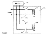
図2Aは、ヌルシフト回路135としての使用に適したヌルシフト回路135Aの概略線図である。ヌルシフト回路135Aは、スイッチ205及び220と、コンデンサ210及び225と、インダクタ215及び230とを含む。ヌルシフト回路135Aは、電力線115に結合され、また例えばトランシーバ145の送信機又は受信機のような通信デバイス201の通信ポートにも結合される。コンデンサ210は0.022マイクロファラッド(μF)の値を有し、コンデンサ225は0.047μFの値を有し、またインダクタ215及び230は各々、5マイクロヘンリ(μH)の値を有する。プロセッサ140(図1)は、電力線115の導線全体にわたるリアクタンスを変化させることによって電力網105の複素インピーダンスを変更するようにスイッチ205及び220を制御する。
FIG. 2A is a schematic diagram of a
スイッチ205及び220の両方が開である回路0を考察する。コンデンサ210及び225並びにインダクタ215及び230は、電力網105から切り離されている。従って、ヌルシフト回路135Aは、オフになっていると見なすことができる。電力網105の複素インピーダンスは、ヌルシフト回路135Aの外部の条件の関数である。この複素インピーダンスの構成をZ0と呼ぶ。
Consider a circuit 0 where both
スイッチ205が閉で、スイッチ220が開である回路1を考察する。インダクタ215及びコンデンサ210が、電力網105内に組み込まれるように切り替えられ、そうすることによって、電力網105の複素インピーダンスに影響を及ぼす。この複素インピーダンスの構成をZ1と呼ぶ。
Consider circuit 1 where
スイッチ205が開で、スイッチ220が閉である回路2を考察する。インダクタ230及びコンデンサ225が、電力網105内に組み込まれるように切り替えられ、そうすることによって、電力網105の複素インピーダンスに影響を及ぼす。この複素インピーダンスの構成をZ2と呼ぶ。
Consider circuit 2 where
スイッチ205及び220の両方が閉である回路3を考察する。コンデンサ210及び225並びにインダクタ215及び230の全てが、電力網105内に組み込まれるように切り替えられ、そうすることによって、電力網105の複素インピーダンスに影響を及ぼす。この複素インピーダンスの構成をZ3と呼ぶ。
Consider circuit 3 in which both
表1に、スイッチ205及び220の4つの構成と、得られた4つの複素インピーダンスZ0〜Z3を要約する。複素インピーダンスZ0〜Z3は、互いに異なる。プロセッサ140は、電力網105の複素インピーダンスを複素インピーダンスZ0〜Z3の1つから複素インピーダンスZ0〜Z3の他の1つに変化させることによって電力網105の複素インピーダンスを変更するようにヌルシフト回路135を制御する。
Table 1 summarizes the four configurations of
表1

ヌルシフト回路135A及び135Bの接続形態とコンデンサ210及び225及び235並びにインダクタ215及び230の値とは、単なる例示である。また、ヌルシフト回路135A及び135Bは4つの複素インピーダンスを有する電力網105を構成することができるものとして示しているが、ヌルシフト回路135は、あらゆる所望の複数の複素インピーダンスを有する電力網105を構成すように実施することができる。例えば、基本的な実施では、ヌルシフト回路135は、単一のインピーダンスを電力網105内に組み込むか又は電力網105から切り離すように切り替え、従って電力網105に対して複素インピーダンスの2つの構成が得られるように実施することができる。一般的に、ヌルシフト回路135は、電力網105の複素インピーダンスを変更可能なあらゆる回路とすることができ、またヌルシフト回路135は、能動又は受動のいずれかの構成要素或いはそれらの組合せで構成することができる。
The connection form of the
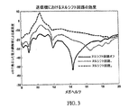
図3は、135Aに類似したヌルシフト回路を送信機において使用したテストのケースにおける、ヌルへの例示的な効果を示すグラフである。図3の縦軸は、減弱度であり、水平軸は、周波数である。14.2MHzの電力線通信搬送波周波数と仮定する。ヌルシフト回路がオフである場合には、14.2MHzにおいて約−55dbのヌルがある。ヌルシフト回路を回路1として構成した場合には、14.2MHzにおける減弱は、約−20dbであり、約35dbの改善となる。ヌルシフト回路を回路2として構成した場合には、14.2MHzにおける減弱は、約−10dbであり、約45dbの改善となる。実際には、各実体面の電力網はそれ自体の固有のインピーダンスの組合せを有するので、実効果は、図3に示すものから変化したものになると思われる。 FIG. 3 is a graph showing an exemplary effect on nulls in a test case using a null shift circuit similar to 135A at the transmitter. The vertical axis in FIG. 3 is the attenuation, and the horizontal axis is the frequency. Assume a power line communication carrier frequency of 14.2 MHz. When the null shift circuit is off, there is approximately -55 db null at 14.2 MHz. When the null shift circuit is configured as the circuit 1 , the attenuation at 14.2 MHz is about −20 db, which is an improvement of about 35 db. When the null shift circuit is configured as the circuit 2 , the attenuation at 14.2 MHz is about −10 db, which is an improvement of about 45 db. In practice, since each power grid has its own inherent impedance combination, the actual effect would be different from that shown in FIG.
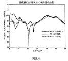
図4は、135Aに類似したヌルシフト回路を受信機において使用したテストのケースにおける、ヌルへの例示的な効果を示すグラフである。図4の縦軸は、減弱度であり、水平軸は、周波数である。12.2MHz及び13.2MHzの実行可能な通信周波数について考える。ヌルシフト回路がオフである場合には、12.2MHzにおいて約−25dbのヌルがあり、また13.2MHzにおいて約−40dbのヌルがある。ヌルシフト回路を回路1として構成した場合には、12.2MHzにおいて約−68dbのヌルが発生し、13.2MHzにおける減弱は約−23dbである。ヌルシフト回路を回路2として構成した場合には、12.2MHzにおける減弱は約−37dbであり、13.2MHzにおける減弱は約−26dbである。従って、12.2MHzの通信周波数については、最も好ましい性能は、ヌルシフト回路をオフにした場合に生じる。しかしながら、13.2MHzの通信周波数については、最も好ましい性能は、回路1の場合に生じる。実際には、各実体面の電力網はそれ自体の固有のインピーダンスの組合せを有するので、実効果は、図4に示すものから変化したものになると思われる。 FIG. 4 is a graph illustrating an exemplary effect on nulls in a test case using a null shift circuit similar to 135A at the receiver. The vertical axis in FIG. 4 is the attenuation, and the horizontal axis is the frequency. Consider feasible communication frequencies of 12.2 MHz and 13.2 MHz. When the null shift circuit is off, there is approximately -25 db null at 12.2 MHz and approximately -40 db null at 13.2 MHz. When the null shift circuit is configured as the circuit 1 , a null of about −68 db is generated at 12.2 MHz, and the attenuation at 13.2 MHz is about −23 db. When the null shift circuit is configured as the circuit 2 , the attenuation at 12.2 MHz is about −37 db, and the attenuation at 13.2 MHz is about −26 db. Therefore, for the 12.2 MHz communication frequency, the most favorable performance occurs when the null shift circuit is turned off. However, for a communication frequency of 13.2 MHz, the most favorable performance occurs with circuit 1 . In practice, since each power grid has its own inherent impedance combination, the actual effect would be different from that shown in FIG.
ヌルシフト回路135及びプロセッサ140の使用に対して、幾つかの別のシナリオが考えられる。すなわち、(1)電力網105の複素インピーダンスを変更することによって、所望の周波数において信号伝達を可能にするようにPLC打消しヌル深さ又はヌル周波数を能動的に変化させること、(2)マスタ通信デバイスを使用して、スレーブユニットからの応答を受信しない場合に電力網105の複素インピーダンスを変更すること、(3)マスタ通信デバイスを使用して、電力網105の複素インピーダンスを変更し、性能を監視し、次に最良の性能が得られるインピーダンスを使用すること、(4)スレーブ通信デバイスを使用して、電力網105の複素インピーダンスを周期的に変更し、次に最良の性能が得られるインピーダンスを使用すること、(5)独立通信デバイスを使用して、個別のマスタ及びスレーブ間の通信を改善するように電力網105の複素インピーダンスを周期的に、無秩序に又は間歇的に変更することである。これらの様々なシナリオは、それらを必ずしもマスタ又はスレーブとして指定せずに送信機及び受信機に使用することができる。
Several alternative scenarios are possible for the use of
当業者が本明細書で説明した教示の様々な変形、組合せ及び変更を考えることができることを理解されたい。本発明は、特許請求の範囲の技術的範囲内に属する全てのそのような変形、組合せ及び変更を包含することを意図している。 It should be understood that those skilled in the art can envision various variations, combinations, and modifications of the teachings described herein. The present invention is intended to embrace all such alterations, combinations and modifications that fall within the scope of the appended claims.
100 PLCシステム
105 電力網
110、125、130 電気コンセント
115 電力線
120、145、150 トランシーバ
135 ヌルシフト回路
140 プロセッサ
155 記憶媒体
100
Claims (24)
前記複素インピーダンスを変更する段階と、
前記変更する段階が前記通信の品質に影響を与えたか否かを判定する段階と、
を含む方法。 A method for enabling communication within a power grid having a complex impedance comprising:
Changing the complex impedance;
Determining whether the step of changing has affected the quality of the communication;
Including methods.
前記変更する段階が、前記信号周波数帯域内での品質を改善する、
請求項1記載の方法。 The communication is performed within a signal frequency band;
Said changing step improves quality within said signal frequency band;
The method of claim 1.
前記電力網内での通信の品質を判定する段階と、
前記品質が許容閾値以下である場合に前記複素インピーダンスを変更する段階と、
を含む方法。 A method for enabling communication within a power grid having a complex impedance comprising:
Determining the quality of communication within the power network;
Changing the complex impedance when the quality is below an acceptable threshold;
Including methods.
前記電力網を介して情報を送信する段階と、
前記複素インピーダンスを変更する段階と、
前記電力網を介して前記情報を再送信する段階と、
を含む方法。 A method for enabling communication within a power grid having a complex impedance comprising:
Transmitting information via the power network;
Changing the complex impedance;
Retransmitting the information via the power network;
Including methods.
前記複素インピーダンスを変更するための回路と、
前記変更が前記通信の品質に影響を与えたか否かを判定するためのプロセッサと、
を含む装置。 An apparatus for enabling communication within a power grid having a complex impedance comprising:
A circuit for changing the complex impedance;
A processor for determining whether the change has affected the quality of the communication;
Including the device.
前記変更が、前記信号周波数帯域内での前記品質を改善する、
請求項12記載の装置。 The communication is performed within a signal frequency band;
The change improves the quality within the signal frequency band;
The apparatus of claim 12.
前記電力網内での通信の品質を判定するためのモジュールと、
前記品質が許容閾値以下である場合に前記複素インピーダンスを変更するように回路を制御するためのモジュールと、
を含むプロセッサ。 A processor for enabling communication within a power grid having a complex impedance,
A module for determining the quality of communication within the power network;
A module for controlling the circuit to change the complex impedance when the quality is below an acceptable threshold;
Including processor.
前記電力網を介して情報を送信するように送信機に通知するためのモジュールと、
前記複素インピーダンスを変更するように回路を制御するためのモジュールと、
前記情報を再送信するように前記送信機に通知するためのモジュールと、
を含むプロセッサ。 A processor for enabling communication within a power grid having a complex impedance,
A module for notifying a transmitter to transmit information via the power network;
A module for controlling the circuit to change the complex impedance;
A module for notifying the transmitter to retransmit the information;
Including processor.
前記プロセッサを制御して前記電力網内での通信の品質を判定するための命令と、
前記品質が許容閾値以下である場合に、前記プロセッサを制御して前記複素インピーダンスを変更するように回路を制御するための命令と、
を含む記憶媒体。 A storage medium comprising instructions for controlling a processor that enables communication within a power network having a complex impedance comprising:
Instructions for controlling the processor to determine the quality of communication within the power network;
Instructions for controlling the circuit to control the processor to change the complex impedance if the quality is below an acceptable threshold;
Including storage medium.
前記プロセッサを制御して前記電力網を介して情報を送信するように送信機に通知するための命令と、
前記プロセッサを制御して前記複素インピーダンスを変更するように回路を制御するための命令と、
前記プロセッサを制御して前記情報を再送信するように前記送信機に通知するための命令と、
を含む記憶媒体。 A storage medium comprising instructions for controlling a processor that enables communication within a power network having a complex impedance comprising:
Instructions for controlling the processor to notify the transmitter to transmit information over the power network;
Instructions for controlling the circuit to control the processor to change the complex impedance;
Instructions for controlling the processor to notify the transmitter to retransmit the information;
Including storage medium.
Applications Claiming Priority (2)
| Application Number | Priority Date | Filing Date | Title |
|---|---|---|---|
| US10/685,868 US7493100B2 (en) | 2003-10-15 | 2003-10-15 | Compensating for dynamic nulls in a power line communication system |
| PCT/US2004/034039 WO2005039070A2 (en) | 2003-10-15 | 2004-10-14 | Compensating for dynamic nulls in a power line communication system |
Publications (2)
| Publication Number | Publication Date |
|---|---|
| JP2007509529A true JP2007509529A (en) | 2007-04-12 |
| JP2007509529A5 JP2007509529A5 (en) | 2007-11-29 |
Family
ID=34465477
Family Applications (1)
| Application Number | Title | Priority Date | Filing Date |
|---|---|---|---|
| JP2006535336A Withdrawn JP2007509529A (en) | 2003-10-15 | 2004-10-14 | Method for correcting dynamic nulls in power line communication systems |
Country Status (5)
| Country | Link |
|---|---|
| US (1) | US7493100B2 (en) |
| EP (1) | EP1678842A2 (en) |
| JP (1) | JP2007509529A (en) |
| CN (1) | CN1890894A (en) |
| WO (1) | WO2005039070A2 (en) |
Cited By (2)
| Publication number | Priority date | Publication date | Assignee | Title |
|---|---|---|---|---|
| JP2014179891A (en) * | 2013-03-15 | 2014-09-25 | Toshiba Toko Meter Systems Co Ltd | Power line carrier communication device |
| JP2015018383A (en) * | 2013-07-10 | 2015-01-29 | 株式会社日本自動車部品総合研究所 | Power supply system |
Families Citing this family (25)
| Publication number | Priority date | Publication date | Assignee | Title |
|---|---|---|---|---|
| US8060566B2 (en) * | 2004-12-01 | 2011-11-15 | Aol Inc. | Automatically enabling the forwarding of instant messages |
| US8406239B2 (en) | 2005-10-03 | 2013-03-26 | Broadcom Corporation | Multi-wideband communications over multiple mediums |
| US8213895B2 (en) | 2005-10-03 | 2012-07-03 | Broadcom Europe Limited | Multi-wideband communications over multiple mediums within a network |
| US7808985B2 (en) | 2006-11-21 | 2010-10-05 | Gigle Networks Sl | Network repeater |
| EP1770870B1 (en) | 2005-10-03 | 2019-04-03 | Avago Technologies International Sales Pte. Limited | Powerline communication device and method |
| DE102006020029B4 (en) * | 2006-04-26 | 2016-06-30 | IAD Gesellschaft für Informatik, Automatisierung und Datenverarbeitung mbH | Adaptive, capacitive coupling circuit and method for message transmission via shielded power cables of an electrical power distribution network |
| US8438239B2 (en) * | 2006-05-11 | 2013-05-07 | Vocollect, Inc. | Apparatus and method for sharing data among multiple terminal devices |
| US7860146B2 (en) | 2006-07-06 | 2010-12-28 | Gigle Networks, Inc. | Adaptative multi-carrier code division multiple access |
| US9705562B2 (en) | 2006-07-25 | 2017-07-11 | Broadcom Europe Limited | Dual transformer communication interface |
| US8213582B2 (en) | 2008-03-14 | 2012-07-03 | Broadcom Europe Limited | Coupling signal processing circuitry with a wireline communications medium |
| US8885814B2 (en) * | 2006-07-25 | 2014-11-11 | Broadcom Europe Limited | Feedback impedance control for driving a signal |
| US7602220B1 (en) | 2008-06-24 | 2009-10-13 | Gigle Semiconductor, Ltd. | Resistor-input transconductor including common-mode compensation |
| US7795973B2 (en) | 2008-10-13 | 2010-09-14 | Gigle Networks Ltd. | Programmable gain amplifier |
| US7956689B2 (en) | 2008-10-13 | 2011-06-07 | Broadcom Corporation | Programmable gain amplifier and transconductance compensation system |
| US8274232B2 (en) | 2010-08-03 | 2012-09-25 | General Electric Company | Lighting system communications apparatus and method |
| US8398435B2 (en) | 2011-05-05 | 2013-03-19 | General Electric Company | Receptacle connector between controller and lighting fixture |
| US8864514B2 (en) | 2010-10-07 | 2014-10-21 | General Electric Company | Controller device |
| US9148936B2 (en) | 2013-04-04 | 2015-09-29 | Abl Ip Holding Llc | Integral dimming photo-control receptacle |
| US9247435B2 (en) | 2014-01-15 | 2016-01-26 | Qualcomm Incorporated | Null beamforming in a communication network |
| US9781814B2 (en) | 2014-10-15 | 2017-10-03 | Abl Ip Holding Llc | Lighting control with integral dimming |
| CA2908835C (en) | 2014-10-15 | 2017-04-04 | Abl Ip Holding Llc | Lighting control with automated activation process |
| US10061403B2 (en) * | 2014-11-04 | 2018-08-28 | Mimio, Llc | Light pen |
| KR102605056B1 (en) * | 2017-03-08 | 2023-11-24 | 로베르트 보쉬 게엠베하 | Method for mitigating transient-based attacks on key agreement methods over instrumentation controller networks |
| US9888542B1 (en) | 2017-04-28 | 2018-02-06 | Abl Ip Holding Llc | Outdoor lighting system controlled using motion sensor interface |
| EP3506516B1 (en) * | 2017-12-28 | 2020-10-28 | Solaredge Technologies Ltd. | Variable impedance circuit |
Citations (5)
| Publication number | Priority date | Publication date | Assignee | Title |
|---|---|---|---|---|
| JPS62163533A (en) * | 1986-01-14 | 1987-07-20 | 松下電器産業株式会社 | Power line carrier communication controller |
| JPH09509815A (en) * | 1994-12-19 | 1997-09-30 | モトローラ・インコーポレイテッド | Method and apparatus for mitigating interference in a communication system |
| JP2002290289A (en) * | 2001-03-27 | 2002-10-04 | Tdk Corp | Power-line carrier communication network system |
| JP2003273784A (en) * | 2002-03-19 | 2003-09-26 | Sumitomo Electric Ind Ltd | Communication method, electric light line communication equipment and electric light line communication system |
| JP2003283387A (en) * | 2002-03-22 | 2003-10-03 | Tdk Corp | Terminal equipment for power line communication system and connection equipment for power line communication system |
Family Cites Families (12)
| Publication number | Priority date | Publication date | Assignee | Title |
|---|---|---|---|---|
| GB1545623A (en) * | 1976-05-19 | 1979-05-10 | Elap | Transmission system and repeater stations therefor |
| JPS58179034A (en) | 1982-04-14 | 1983-10-20 | Sharp Corp | Data transmitting system |
| US4479215A (en) | 1982-09-24 | 1984-10-23 | General Electric Company | Power-line carrier communications system with interference avoidance capability |
| US4622441A (en) * | 1984-06-21 | 1986-11-11 | Itt Corporation | Two-wire/four wire communication interface with noise rejection |
| US4866704A (en) * | 1988-03-16 | 1989-09-12 | California Institute Of Technology | Fiber optic voice/data network |
| US5426404A (en) * | 1994-01-28 | 1995-06-20 | Motorola, Inc. | Electrical circuit using low volume multilayer transmission line devices |
| US5929749A (en) * | 1997-11-13 | 1999-07-27 | Slonim; Michael | System for improved communication and control over power lines |
| US20020080719A1 (en) * | 2000-12-22 | 2002-06-27 | Stefan Parkvall | Scheduling transmission of data over a transmission channel based on signal quality of a receive channel |
| US6747569B2 (en) * | 2001-02-02 | 2004-06-08 | Dbi Corporation | Downhole telemetry and control system |
| US6741143B2 (en) * | 2001-06-01 | 2004-05-25 | Rf Technologies Corporation | Apparatus and method for in-process high power variable power division |
| JP3744435B2 (en) | 2002-02-13 | 2006-02-08 | 住友電気工業株式会社 | Power line carrier communication modem |
| US7072620B2 (en) * | 2003-04-03 | 2006-07-04 | Kyocera Wireless Corp. | System and method for regulating antenna electrical length |
-
2003
- 2003-10-15 US US10/685,868 patent/US7493100B2/en active Active
-
2004
- 2004-10-14 CN CNA2004800365950A patent/CN1890894A/en active Pending
- 2004-10-14 EP EP04800477A patent/EP1678842A2/en not_active Withdrawn
- 2004-10-14 WO PCT/US2004/034039 patent/WO2005039070A2/en active Application Filing
- 2004-10-14 JP JP2006535336A patent/JP2007509529A/en not_active Withdrawn
Patent Citations (5)
| Publication number | Priority date | Publication date | Assignee | Title |
|---|---|---|---|---|
| JPS62163533A (en) * | 1986-01-14 | 1987-07-20 | 松下電器産業株式会社 | Power line carrier communication controller |
| JPH09509815A (en) * | 1994-12-19 | 1997-09-30 | モトローラ・インコーポレイテッド | Method and apparatus for mitigating interference in a communication system |
| JP2002290289A (en) * | 2001-03-27 | 2002-10-04 | Tdk Corp | Power-line carrier communication network system |
| JP2003273784A (en) * | 2002-03-19 | 2003-09-26 | Sumitomo Electric Ind Ltd | Communication method, electric light line communication equipment and electric light line communication system |
| JP2003283387A (en) * | 2002-03-22 | 2003-10-03 | Tdk Corp | Terminal equipment for power line communication system and connection equipment for power line communication system |
Cited By (2)
| Publication number | Priority date | Publication date | Assignee | Title |
|---|---|---|---|---|
| JP2014179891A (en) * | 2013-03-15 | 2014-09-25 | Toshiba Toko Meter Systems Co Ltd | Power line carrier communication device |
| JP2015018383A (en) * | 2013-07-10 | 2015-01-29 | 株式会社日本自動車部品総合研究所 | Power supply system |
Also Published As
| Publication number | Publication date |
|---|---|
| WO2005039070A2 (en) | 2005-04-28 |
| US20050085211A1 (en) | 2005-04-21 |
| US7493100B2 (en) | 2009-02-17 |
| CN1890894A (en) | 2007-01-03 |
| WO2005039070A3 (en) | 2005-06-09 |
| EP1678842A2 (en) | 2006-07-12 |
Similar Documents
| Publication | Publication Date | Title |
|---|---|---|
| JP2007509529A (en) | Method for correcting dynamic nulls in power line communication systems | |
| US11329693B2 (en) | Dynamic medium switch in co-located PLC and RF networks | |
| US9647722B2 (en) | Adaptive line equalizer for improving data communication over less than perfect power lines or transmission lines | |
| EP1292060B1 (en) | Data transmission with a signalling subchannel | |
| JP6067581B2 (en) | Multiband channel capacity for meter networks | |
| US9369260B2 (en) | Division free duplexing networks | |
| KR20050115322A (en) | Power line terminating circuit and method, and power line relay device | |
| JP2008148293A (en) | Transmitting circuit and system | |
| US9172430B2 (en) | High performance PLC cluster system | |
| US20110228867A1 (en) | Remote antenna system | |
| US8804793B2 (en) | Method and apparatus for fast link recovery | |
| WO2013188766A1 (en) | Powerline communication diversity coupling technique | |
| TW201101713A (en) | Adjustable receive filter | |
| JP2010273275A (en) | Power line communication apparatus, method thereof, and power line communication network | |
| JP4543817B2 (en) | Power line carrier communication equipment | |
| JP2005269416A (en) | Communication device and communication system | |
| JPH09102763A (en) | Impedance matching circuit | |
| Tsuzuki et al. | Dual mode transmission PLC system with an EMC considered algorithm | |
| JP2008187366A (en) | Communication equipment | |
| TWI244854B (en) | Techniques to perform line qualification | |
| KR20060103533A (en) | Circuit arrangement for transmission of data signals from and/or to household appliances | |
| JP2006135872A (en) | Receiving apparatus and wireless communication system | |
| JP2018170619A (en) | Wireless communication apparatus and wireless communication system using the same | |
| KR100880333B1 (en) | Transceiver for cancelling radio frequency interference in VDSL System | |
| JPH11177368A (en) | Emi filter, datatransmitter-receiver using it and lan system |
Legal Events
| Date | Code | Title | Description |
|---|---|---|---|
| A521 | Written amendment |
Free format text: JAPANESE INTERMEDIATE CODE: A523 Effective date: 20071010 |
|
| A621 | Written request for application examination |
Free format text: JAPANESE INTERMEDIATE CODE: A621 Effective date: 20071010 |
|
| A977 | Report on retrieval |
Free format text: JAPANESE INTERMEDIATE CODE: A971007 Effective date: 20100412 |
|
| A131 | Notification of reasons for refusal |
Free format text: JAPANESE INTERMEDIATE CODE: A131 Effective date: 20100420 |
|
| A02 | Decision of refusal |
Free format text: JAPANESE INTERMEDIATE CODE: A02 Effective date: 20101005 |
|
| A761 | Written withdrawal of application |
Free format text: JAPANESE INTERMEDIATE CODE: A761 Effective date: 20101118 |