JP2005291327A - Air damper - Google Patents
Air damper Download PDFInfo
- Publication number
- JP2005291327A JP2005291327A JP2004106032A JP2004106032A JP2005291327A JP 2005291327 A JP2005291327 A JP 2005291327A JP 2004106032 A JP2004106032 A JP 2004106032A JP 2004106032 A JP2004106032 A JP 2004106032A JP 2005291327 A JP2005291327 A JP 2005291327A
- Authority
- JP
- Japan
- Prior art keywords
- cylinder
- cap
- piston
- air damper
- peripheral surface
- Prior art date
- Legal status (The legal status is an assumption and is not a legal conclusion. Google has not performed a legal analysis and makes no representation as to the accuracy of the status listed.)
- Pending
Links
Images

Abstract
Description
この発明は、例えば、自動車のグローブボックス等に使用されるシリンダ型のエアダンパの改良に関する。 The present invention relates to an improvement in a cylinder-type air damper used for, for example, a glove box of an automobile.
従来のこの種のエアダンパとして、特許文献1に開示されたものが存在する。同文献1に開示されたエアダンパは、両端が開口する筒状体からなるシリンダと、ピストンロッドの先端部に装着されシリンダの内周面に密着して摺動するピストンと、シリンダの一端開口部に装着された弾性材料かならるキャップとを備えている。
キャップは、弁機構を構成しており、ピストンロッドの往復移動に伴い、シリンダ内周面との間を弾力的に開閉する構成となっている。また、キャップの周面には、オリフィス溝が形成されており、シリンダ内周面にキャップが密着したとき、このオリフィス溝を通してシリンダ内に空気が流入する。このオリフィス溝を通過する空気の流動抵抗がピストンに作用してエアダンパとしての機能を発揮する。
A conventional air damper of this type is disclosed in
The cap constitutes a valve mechanism, and is configured to elastically open and close between the cylinder inner peripheral surface as the piston rod reciprocates. An orifice groove is formed on the peripheral surface of the cap. When the cap is in close contact with the inner peripheral surface of the cylinder, air flows into the cylinder through the orifice groove. The flow resistance of the air passing through the orifice groove acts on the piston, and functions as an air damper.
すなわち、ピストンロッドを一方向へ移動させるときは、キャップが弾性的に変形してシリンダ内周面との間に間隙を生じさせ、これにより、シリンダ内の空気を速やかに逃がすか、またはシリンダ内に空気を速やかに流入させるので、ピストンがシリンダー内を抵抗なく移動することができる。 That is, when moving the piston rod in one direction, the cap is elastically deformed to create a gap with the cylinder inner peripheral surface, thereby allowing air in the cylinder to escape quickly or in the cylinder. Since air is allowed to flow quickly into the piston, the piston can move within the cylinder without resistance.
一方、ピストンロッドを逆方向へ移動させるときは、キャップがシリンダの内周面に密着し、オリフィス溝を通してシリンダ内に空気が流入するか、またはシリンダ内の空気を逃がすので、ピストンロッドはオリフィス溝を通る空気の流動抵抗を受けてゆっくりと移動する。
しかしながら、上記従来のエアダンパにあっては、次のような問題があった。すなわち、オリフィス溝を通してシリンダ内に空気を流入させるか、またはシリンダ内の空気を逃がす際、当該オリフィス溝の内壁には大きな圧力が作用する。上記従来のエアダンパは、弾性材料からなるキャップの周面にオリフィス溝が形成されていたので、かかる圧力の作用によりキャップが変形し、オリフィス溝の断面積が不規則に変化してしまう。その結果、ピストンロッドに作用する抵抗が不規則となり、ピストンロッドの動作が不安定となる欠点があった。 However, the conventional air damper has the following problems. That is, when air is introduced into the cylinder through the orifice groove or the air in the cylinder is released, a large pressure acts on the inner wall of the orifice groove. In the conventional air damper, since the orifice groove is formed on the peripheral surface of the cap made of an elastic material, the cap is deformed by the action of the pressure, and the sectional area of the orifice groove changes irregularly. As a result, there is a drawback that the resistance acting on the piston rod becomes irregular and the operation of the piston rod becomes unstable.
この種のエアダンパは、例えば、自動車のグローブボックスに装着される場合にあっては、当該グローブボックスをゆっくりと安定感をもって開放させることが期待される。グローブボックスが、例えば、ゆっくり開いている途中で急に早く開くなど、その開放動作が不安定であっては、自動車そのものの高級感が損なわれるばかりでなく、グローブボックスの急な開放によってその内部に収容してあった物品が飛び出て、損傷するおそれもある。 For example, when this type of air damper is mounted on a glove box of an automobile, it is expected that the glove box is slowly opened with a sense of stability. If the opening operation is unstable, such as when the glove box opens slowly and quickly, for example, when it is slowly opening, not only the luxury of the car itself is impaired, but also the inside of the glove box is suddenly opened There is also a risk that the articles contained in the container will pop out and be damaged.
本発明は、上述したような従来のエアダンパが抱える課題を有効に解決するために開発されたもので、請求項1の発明は、両端が開口した筒状のシリンダと、シリンダの中空部内で同シリンダの内周面に密接して摺動自在なピストンと、シリンダの一端開口部に装着されるキャップとを備えたエアダンパにおいて、
キャップは、ピストンの移動に伴うシリンダ内部の圧力変動に応じて開閉する弁構造を有し、
かつ、キャップの外周面が密接するシリンダの内周面に、該シリンダの中空部を大気に連通させるオリフィス溝を形成したことを特徴とする。
The present invention was developed in order to effectively solve the problems of the conventional air damper as described above. The invention of
The cap has a valve structure that opens and closes according to pressure fluctuations inside the cylinder as the piston moves,
In addition, an orifice groove for communicating the hollow portion of the cylinder with the atmosphere is formed on the inner peripheral surface of the cylinder, which is in close contact with the outer peripheral surface of the cap.
また、請求項2の発明は、ピストンがキャップから離れる方向へ移動するときの吸引圧力によって、キャップの外周面がシリンダの内周面に密接して閉じる構造をした請求項1のエアダンパを前提として、
前記オリフィス溝が、シリンダの一端開口部から軸方向に沿ってピストンの移動領域にある任意の内部位置まで延長して形成してあることを特徴とする。
Further, the invention of
The orifice groove is formed so as to extend from an opening at one end of the cylinder to an arbitrary internal position in the moving region of the piston along the axial direction.
請求項3の発明は、請求項2を前提として、前記オリフィス溝が、延長端である前記内部位置に向けて任意の位置から断面積を徐々に小さく変化させてあることを特徴とする。
The invention of
請求項4の発明は、請求項1乃至3のいずれか一項を前提として、前記キャップが、内部に弁構造を有することを特徴とする。 According to a fourth aspect of the present invention, on the premise of any one of the first to third aspects, the cap has a valve structure inside.
よって、請求項1の発明にあっては、硬質なシリンダの内周面にオリフィス溝を形成することで、一定断面積の通気路を安定して確保することができる。その結果、オリフィス溝を通過する空気の流動抵抗が安定し、ひいてはピストンの動作が安定する。
なお、本発明は、キャップを柔軟性または弾力性を有する材料で形成する場合に、顕著な効果を奏するが、キャップの材質は本発明の必須要件ではない。
Therefore, according to the first aspect of the present invention, by forming the orifice groove on the inner peripheral surface of the hard cylinder, it is possible to stably secure the air passage having a constant cross-sectional area. As a result, the flow resistance of the air passing through the orifice groove is stabilized, and consequently the operation of the piston is stabilized.
In addition, although this invention has a remarkable effect when forming a cap with the material which has a softness | flexibility or elasticity, the material of a cap is not an essential requirement of this invention.
請求項2の発明にあっては、オリフィス溝をピストン移動領域にある任意の内部位置まで延長したので、その延長端をピストンが通過するまで、キャップ側とピストン側の双方からオリフィス溝を通して、キャップとピストンの間にある内部空間に空気が流入するので、ピストンに作用する空気の流動抵抗が緩和されてピストンの移動がいくぶん滑らかになる。
例えば、慣性力が作用しない始動時には、ピストンに作用する引っ張り荷重またはモーメントが比較的小さい場合が多い。このような場合にあっても、請求項2の構成によれば、ピストンを滑らかに始動させることができる。
In the invention of
For example, at the time of start-up where no inertial force acts, the tensile load or moment acting on the piston is often relatively small. Even in such a case, according to the configuration of the second aspect, the piston can be started smoothly.
さらに、請求項3の発明にあっては、始動時にピストンを滑らかに移動させ、しかもオリフィス溝の断面積が延長端に向かって徐々に小さく変化することから、ピストンに作用する空気の流動抵抗が徐々に大きくなっていく。
これにより、例えば、ピストンに作用する引っ張り荷重またはモーメントが、ピストンの移動に伴い徐々に大きくなっていく場合に、この変化に対応してピストンを滑らかに始動させることができる。一般に、自動車のグローブボックスに取り付けられるエアダンパには、リッドの開放時にこのように変化するモーメントがピストンに作用する。
Further, in the invention of
Thereby, for example, when the tensile load or moment acting on the piston gradually increases as the piston moves, the piston can be smoothly started in response to this change. Generally, in an air damper attached to a glove box of an automobile, a moment that changes in this way acts on a piston when the lid is opened.
請求項4の発明にあっては、キャップの内部に弁構造を形成することで、シリンダ内周面と密接するキャップ外周面の長さを広げることが可能となり、その結果、オリフィス溝も充分な長さを確保して所望の通気抵抗を付与することができる。 In the invention of claim 4, by forming the valve structure inside the cap, it is possible to increase the length of the outer peripheral surface of the cap that is in close contact with the inner peripheral surface of the cylinder. As a result, the orifice groove is also sufficient. A desired ventilation resistance can be provided by securing the length.
以上説明したとおり、本発明によれば、弾性部材科からなるキャップに対し、シリンダの内周面にオリフィス溝を形成することで、一定断面積の通気路を安定して確保することができる。その結果、オリフィス溝を通過する空気の流動抵抗が安定し、ひいてはピストンの動作が安定する。 As described above, according to the present invention, an air passage having a constant cross-sectional area can be stably secured by forming an orifice groove on the inner peripheral surface of the cylinder with respect to the cap made of the elastic member family. As a result, the flow resistance of the air passing through the orifice groove is stabilized, and consequently the operation of the piston is stabilized.
以下、この発明の実施の形態について図面を参照して詳細に説明する。
《第1実施形態》
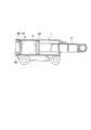
図1は本発明の第1実施形態に係るエアダンパの全体構造を示す正面断面図である。
エアダンパは、両端が開口した筒状のシリンダ1と、該シリンダ1内を移動するピストン2と、シリンダ1の一端開口部を閉塞するキャップ3とを備えている。
Hereinafter, embodiments of the present invention will be described in detail with reference to the drawings.
<< First Embodiment >>
FIG. 1 is a front sectional view showing the entire structure of the air damper according to the first embodiment of the present invention.
The air damper includes a
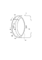
シリンダ1は、油成分を含む熱可塑性エラストマーで成形されており、中間部内周面は、ピストン2が密接して摺動する平滑面に形成されている。シリンダ1の一端開口部には、キャップ3の装着部10が形成されている。キャップ装着部10は、図2に拡大して示すように、中間部11よりも内径が大きくしてあり、中間部11との境界部分は傾斜段部12となっている。この傾斜段部12は、後述するキャップ3の開閉弁部31の外周面に対応する傾斜角度に設定してある。また、シリンダ1の他端開口部は、ピストンロッド4が挿通できる内径としてある。
The
キャップ装着部10には、複数の係止孔13とオリフィス溝14とが形成してある。図2では、オリフィス溝14が1本形成されているが、必要に応じてオリフィス溝14を複数本形成してもよい。オリフィス溝14は、シリンダ1の軸方向に沿って一端縁から傾斜段部12にかけて形成されている。
A plurality of
ピストン2は、熱可塑性エラストマーで棒状のピストンロッド4と一体に成形されており、外周面に円環状のシール突起20が一体形成されている。シール突起20は、従来のOリングに相当するもので、容易に撓んで、ピストン2の本体部とシリンダ1の内周面間との間を密閉するとともに、シリンダ1の内周面に密接して摺動する。なお、シール突起20の代わりに、従来と同様にOリングをピストン2の外周面に装着してもよい。
The
キャップ3は、図1に示すように、シリンダ1の一端開口部に形成したキャップ装着部10に嵌め込まれる基部30と、基部30の一端面から膨出する傘状の開閉弁部31とを有している。キャップ3は、柔軟で弾力性に富んだ熱可塑性エラストマーで一体に成形されている。
キャップ3の基部30には、図3(b)(d)に拡大して示すように、複数の係合突起32が外周面から突出して形成してあり、これらの係合突起32をシリンダ1のキャップ装着部10に形成した係止孔13に係合させることで、キャップ3のシリンダ1からの抜けが防止されている。
As shown in FIG. 1, the
As shown in enlarged views in FIGS. 3B and 3D, the
ここで、シリンダ1のキャップ装着部10に形成した係止孔13は、キャップ3の基部30に形成した係合突起32よりも軸方向の幅を広くしてあり、係止孔13内で係合突起32が軸方向に移動可能となっており、これと一体にシリンダ1は軸方向に移動可能である。
Here, the locking
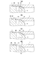
キャップ3は、ピストン2のシリンダ1内での移動に伴う圧力の作用をもって、軸方向に移動する。そして、キャップ3がシリンダ1の内側から押圧力を受け、一端開口部から抜け出ようとする方向(図3の左方向)に移動したときは、図3(b)に示すように、基部30の外周端縁がシリンダ1の係止孔13よりも外側に位置することとなり、これにより基部30の内側が係止孔13を通して外部と連通する。
このとき、キャップ3の開閉弁部31は、図3(a)(b)に示すように、シリンダ1の内側から受ける押圧力によって先端部が弾力的に撓んで、シリンダ1内の空気を係止孔13へと流動させる。
The
At this time, as shown in FIGS. 3A and 3B, the opening /
一方、キャップ3がシリンダ1の内側から吸引圧力を受けて、シリンダ1の内側に引っ込む方向(図3の右方向)に移動したときは、図3(d)に示すように、基部30の外周縁がシリンダ1の係止孔13よりも内側にある内周面と密接し、係止孔13はキャップ3の基部30によって密閉される。
このとき、キャップ3の開閉弁部31は、図3(d)に示すように、シリンダ1の内側から受ける吸引圧力によって、シリンダ1のキャップ装着部10に形成した傾斜段部12に密接する。
この状態にあっても、オリフィス溝14を通してシリンダ1の中空部内は外部と連通しているので(図3(c)参照)、このオリフィス溝14からシリンダ1内部へ空気が流入する。ただし、オリフィス溝14を通して流入する空気の量は少なく、したがって、ピストン2は、オリフィス溝14を通過する空気の流動抵抗を受けてゆっくりと移動することになる。
On the other hand, when the
At this time, the on-off
Even in this state, the hollow portion of the
上述した構成のエアダンパを自動車のグローブボックスで使用する場合には、具体的には図示しないが、従来と同様に、シリンダ1をその取付部を介してインストルメントパネル側に回動可能に固定し、ピストンロッド4をその先端部の取付孔を介してグローブボックスのリッドへ回動可能に固定すればよい。
When the air damper having the above-described configuration is used in a glove box of an automobile, although not specifically illustrated, the
そして、グローブボックスのリッドを開方向へ移動させると、ピストンロッド4がシリンダ1内から徐々に引き出されて、ピストン2がシリンダ1内を同方向に摺動する。このピストン2の移動により、キャップ3には吸引圧力が作用して、図3(c)(d)に示したようにシリンダ1内周面にキャップ3の開閉弁部31が密接する状態が形成される。したがって、空気はオリフィス1溝14のみを通過してシリンダ1ー1内に流入し、これにより、ダンパー効果を得て、グローブボックスはゆっくりと開放状態に移動することが保障できる。
When the lid of the glove box is moved in the opening direction, the piston rod 4 is gradually pulled out from the
このときも、オリフィス溝14は剛性の高いシリンダ1の内周面に形成されているので、その内部を流れる空気の流動抵抗が大きくとも、断面積は変わらず、したがって当該流動抵抗が安定しており、ピストン2ひいてはグローブボックスの動作が安定する。
Also at this time, since the
一方、グローブボックスを閉方向へ移動させると、これに応じて、ピストンロッド4がシリンダ1内に徐々に押し込まれるので、ピストン2もシリンダ1内で同方向に摺動する。このピストン2の移動により、キャップ3にはシリンダ1の内側から押圧力が作用して、図3(a)(b)に示したように開閉弁部31が撓みシリンダ1内周面との間に隙間を形成するとともに、キャップ3が外側(図の左方向)に移動して係止孔13も開放される。したがって、シリンダ1内部の空気が、開閉弁部31とシリンダ1内周面との間の隙間から係止孔13を通り外部へ効率よく逃がされる。これにより、ピストン2は抵抗も少なく元の位置に復帰することが可能となって、グローブボックスの速やかな閉じ動作を実現できる。
On the other hand, when the glove box is moved in the closing direction, the piston rod 4 is gradually pushed into the
《第2実施形態》
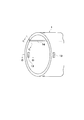
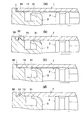
次に、図4および図5を参照して、本発明の第2実施形態に係るエアダンパについて説明する。なお、図4は図2に、図5(a)〜(d)は図3(a)〜(d)にそれぞれ対応しており、同一部分には同一符号を付してある。
<< Second Embodiment >>
Next, an air damper according to a second embodiment of the present invention will be described with reference to FIGS. 4 and 5. 4 corresponds to FIG. 2, and FIGS. 5A to 5D correspond to FIGS. 3A to 3D, respectively, and the same portions are denoted by the same reference numerals.
本実施形態では、シリンダ1の一端開口部を中間部11と同じ内径として、それらの境界部分に傾斜段部12を形成しない構成としてある。これにより、シリンダ1の形状が簡素化されて、成形が容易となる。
In this embodiment, it is set as the structure which does not form the
さらに本実施形態では、オリフィス溝14をシリンダ1の一端開口部から軸方向に沿ってピストン2の移動領域まで延長して形成してある。オリフィス溝14の長さは、必要に応じて任意に設定することができる。
このように形成したオリフィス溝14は、第1実施形態と同様に、キャップ3側からの空気をシリンダ1内に流入させる通路を形成する。しかも、このオリフィス溝14は、ピストン2が移動する際に、キャップ3とピストン2の間に形成された内部空間内に、ピストン2の背部から空気を流入させる通路としても機能する。すなわち、オリフィス溝14の延長端をピストン2が通過するまでは、キャップ3側とピストン2側の双方からオリフィス溝14を通して、キャップ3とピストン2の間にある内部空間に空気が流入するので、ピストン2に作用する空気の流動抵抗が緩和されてピストン2の移動をいくぶん滑らかにすることができる。
Furthermore, in the present embodiment, the
The
ピストン2の始動時は、慣性力が作用していないので、ピストン2を移動させるのに大きな引っ張り荷重またはモーメントが必要になるが、本実施形態の構成によれば、かかる始動時に、オリフィス溝14の上記機能をもってピストン2を滑らかに移動させることが可能となる。
When the
《第3実施形態》
次に、図6を参照して、本発明の第3実施形態に係るエアダンパについて説明する。なお、図6(a)〜(d)は図5(a)〜(d)にそれぞれ対応しており、同一部分には同一符号を付してある。
<< Third Embodiment >>
Next, an air damper according to a third embodiment of the present invention will be described with reference to FIG. 6A to 6D correspond to FIGS. 5A to 5D, respectively, and the same portions are denoted by the same reference numerals.
本実施形態のエアダンパは、第2実施形態で延長して形成したオリフィス溝14の断面積を、延長端に向かって任意の位置から徐々に小さく変化させた構成となっている。オリフィス溝14の断面積を変化させる開始位置は、必要に応じて任意に設定することができる。
このように形成したオリフィス溝14の断面積を変化させることで、当該部分をピストン2が通過するとき、ピストン2に作用する空気の流動抵抗が徐々に大きくなっていく。
これにより、例えば、ピストン2に作用する引っ張り荷重またはモーメントが、ピストン2の移動に伴い徐々に大きくなっていく場合に、この変化に対応してピストン2を滑らかに始動させることができる。
The air damper of the present embodiment has a configuration in which the sectional area of the
By changing the cross-sectional area of the
Thereby, for example, when the tensile load or moment acting on the
一般に、自動車のグローブボックスを開閉するリッドは、下端を回動支点として閉塞時にはほぼ垂直姿勢を保ち、その姿勢から回動して開き位置では水平姿勢となる。したがって、閉塞状態から開き動作が実行された後、しばらくの間はリッドの自重によるモーメントが小さい。このような構造をしたグローブボックスに本実施形態のエアダンパを取り付ければ、リッドの自重によるモーメントの小さい開き初めにおいて、上記オリフィス溝14の作用をもってピストン2を滑らかに移動させ、リッドの自重によるモーメントが大きくなるにしたがい、オリフィス溝14の断面積の変化による通気抵抗を大きくすることが可能となるため、リッドを緩やかに安定して開くことができる。
In general, a lid that opens and closes a glove box of an automobile maintains a substantially vertical posture when closed with the lower end as a rotation fulcrum, and rotates from that posture to a horizontal posture at an open position. Therefore, after the opening operation is executed from the closed state, the moment due to the weight of the lid is small for a while. If the air damper according to the present embodiment is attached to the glove box having such a structure, the
《第4実施形態》
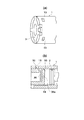
次に、図7を参照して、本発明の第4実施形態に係るエアダンパについて説明する。
本実施形態のエアダンパは、キャップ3の内部に弁構造を形成してある。図7に示す構造では、キャップ3を筒状に形成し、その内側一端面に円盤状の蓋部35を一体形成するとともに、中空部内に舌片状の開閉弁部36を一体形成した構成となっている。蓋部35の中心には、通気孔35aが形成してあり、シリンダ1内の圧力変化に伴い、この通気孔に開閉弁部36が接離する。
<< 4th Embodiment >>
Next, an air damper according to a fourth embodiment of the present invention will be described with reference to FIG.
The air damper of this embodiment has a valve structure formed inside the
さて、既述した第1〜第3実施形態では、キャップ3の一端から外径方向に広がる傘状の開閉弁部31を形成し、この開閉弁部31がシリンダ1の内周面と接離する弁構造としてあったが、この構成では、オリフィス溝14が傘状の開閉弁部31と接触する短い区間でしか通気抵抗を調整することができないので、大きな通気抵抗を得にくい。
これに対し、上記構成の本実施形態は、キャップ3の内部に弁構造を形成することで、シリンダ1の内周面と密接するキャップ外周面の長さを広げることが可能となり、その結果、オリフィス溝14も充分な長さを確保して所望の通気抵抗を付与することができる。
In the first to third embodiments described above, the umbrella-shaped on-off
On the other hand, in the present embodiment having the above configuration, it is possible to increase the length of the outer peripheral surface of the cap that is in close contact with the inner peripheral surface of the
なお、本発明は上述した実施形態に限定されるものではない。本発明のエアダンパは、自動車のグローブボックスの開閉に好適であるが、これに用途が限定されることはない。また、キャップに形成する弁構造も、上述した各実施形態で示した構造以外に、種々の構造を採用することが可能である。さらに、エアダンパの全体構造についても、図1に示したような構造に限定されるものではなく、シリンダと、ピストンと、キャップとを備えていれば、種々の構造を採用することができる。 In addition, this invention is not limited to embodiment mentioned above. The air damper of the present invention is suitable for opening and closing a glove box of an automobile, but the application is not limited thereto. In addition, the valve structure formed on the cap can employ various structures other than the structures shown in the above-described embodiments. Further, the overall structure of the air damper is not limited to the structure as shown in FIG. 1, and various structures can be employed as long as the cylinder, the piston, and the cap are provided.
1:シリンダ、2:ピストン、3:キャップ、4:ピストンロッド、10:キャップ装着部、11:中間部、12:傾斜段部、13:係止孔、14:オリフィス溝、20:シール突起、30:基部、31:開閉弁部、32:係合突起、35:蓋部、36:開閉弁部
1: cylinder, 2: piston, 3: cap, 4: piston rod, 10: cap mounting portion, 11: intermediate portion, 12: inclined step portion, 13: locking hole, 14: orifice groove, 20: seal protrusion, 30: Base, 31: Open / close valve, 32: Engagement protrusion, 35: Lid, 36: Open / close valve
Claims (4)
前記キャップは、前記ピストンの移動に伴う前記シリンダ内部の圧力変動に応じて開閉する弁構造を有し、
かつ、少なくとも前記キャップの外周面が密接する前記シリンダの内周面に、該シリンダの中空部を大気に連通させるオリフィス溝を形成したことを特徴とするエアダンパ。 An air damper comprising: a cylindrical cylinder having both ends open; a piston that is slidable in close contact with an inner peripheral surface of the cylinder in a hollow portion of the cylinder; and a cap that is attached to one end opening of the cylinder. ,
The cap has a valve structure that opens and closes according to a pressure fluctuation inside the cylinder accompanying the movement of the piston,
An air damper is characterized in that an orifice groove is formed on at least the inner peripheral surface of the cylinder, which is in close contact with the outer peripheral surface of the cap, for communicating the hollow portion of the cylinder with the atmosphere.
前記オリフィス溝は、前記シリンダの一端開口部から軸方向に沿って前記ピストンの移動領域にある任意の内部位置まで延長して形成してあることを特徴とするエアダンパ。 2. The air damper according to claim 1, wherein the outer peripheral surface of the cap closes closely to the inner peripheral surface of the cylinder by a suction pressure when the piston moves away from the cap.
The air damper is characterized in that the orifice groove is formed to extend from one end opening of the cylinder along an axial direction to an arbitrary internal position in a moving region of the piston.
The air damper according to any one of claims 1 to 3, wherein the cap has a valve structure therein.
Priority Applications (1)
| Application Number | Priority Date | Filing Date | Title |
|---|---|---|---|
| JP2004106032A JP2005291327A (en) | 2004-03-31 | 2004-03-31 | Air damper |
Applications Claiming Priority (1)
| Application Number | Priority Date | Filing Date | Title |
|---|---|---|---|
| JP2004106032A JP2005291327A (en) | 2004-03-31 | 2004-03-31 | Air damper |
Publications (1)
| Publication Number | Publication Date |
|---|---|
| JP2005291327A true JP2005291327A (en) | 2005-10-20 |
Family
ID=35324490
Family Applications (1)
| Application Number | Title | Priority Date | Filing Date |
|---|---|---|---|
| JP2004106032A Pending JP2005291327A (en) | 2004-03-31 | 2004-03-31 | Air damper |
Country Status (1)
| Country | Link |
|---|---|
| JP (1) | JP2005291327A (en) |
Cited By (5)
| Publication number | Priority date | Publication date | Assignee | Title |
|---|---|---|---|---|
| JP2008032206A (en) * | 2006-05-23 | 2008-02-14 | Shigeo Ono | Drawer air damper |
| WO2008123198A1 (en) * | 2007-03-30 | 2008-10-16 | Nifco Inc. | Damper device |
| WO2009154183A1 (en) * | 2008-06-18 | 2009-12-23 | 株式会社ニフコ | Damper device |
| WO2011037007A1 (en) * | 2009-09-25 | 2011-03-31 | 株式会社ニフコ | Damper device |
| JP2011220534A (en) * | 2007-03-30 | 2011-11-04 | Nifco Inc | Damper device |
-
2004
- 2004-03-31 JP JP2004106032A patent/JP2005291327A/en active Pending
Cited By (10)
| Publication number | Priority date | Publication date | Assignee | Title |
|---|---|---|---|---|
| JP2008032206A (en) * | 2006-05-23 | 2008-02-14 | Shigeo Ono | Drawer air damper |
| WO2008123198A1 (en) * | 2007-03-30 | 2008-10-16 | Nifco Inc. | Damper device |
| JP2011220534A (en) * | 2007-03-30 | 2011-11-04 | Nifco Inc | Damper device |
| WO2009154183A1 (en) * | 2008-06-18 | 2009-12-23 | 株式会社ニフコ | Damper device |
| JP2010001920A (en) * | 2008-06-18 | 2010-01-07 | Nifco Inc | Damper device |
| CN102066802A (en) * | 2008-06-18 | 2011-05-18 | 株式会社利富高 | Damper device |
| US8453810B2 (en) | 2008-06-18 | 2013-06-04 | Nifco Inc. | Damper device |
| WO2011037007A1 (en) * | 2009-09-25 | 2011-03-31 | 株式会社ニフコ | Damper device |
| JP2011069424A (en) * | 2009-09-25 | 2011-04-07 | Nifco Inc | Damper device |
| CN102549297A (en) * | 2009-09-25 | 2012-07-04 | 株式会社利富高 | Damper device |
Similar Documents
| Publication | Publication Date | Title |
|---|---|---|
| US8291547B2 (en) | Cushion clip | |
| US8453810B2 (en) | Damper device | |
| KR100927537B1 (en) | Damper device | |
| KR0141856B1 (en) | Air damper | |
| US9739327B2 (en) | Cushion clip | |
| JP2007147076A (en) | Cushioning adjustment element | |
| JP2010265990A (en) | Air damper | |
| JP6368549B2 (en) | Air damper | |
| JP2005291327A (en) | Air damper | |
| US8528708B2 (en) | Air damper | |
| US20180259026A1 (en) | Damper | |
| US6578832B2 (en) | Air damper used in glove box of automobile | |
| JP2007205494A (en) | Shock absorber | |
| KR101232844B1 (en) | Air damper | |
| JP4260949B2 (en) | Air damper | |
| JP2006090502A (en) | Coupling device for damper | |
| JPWO2018174024A1 (en) | Air damper | |
| KR102616042B1 (en) | Air damper for automobiles | |
| US20120217107A1 (en) | Damper device | |
| KR101674801B1 (en) | Air Damper with Air Buffer | |
| JP4636987B2 (en) | Air damper | |
| KR20240038335A (en) | Air damper for automobiles | |
| JP7449885B2 (en) | damper device | |
| WO2022181353A1 (en) | Damper device | |
| KR20230108032A (en) | Damper for Glove Box in Vehicle and Glove box using thereof |
Legal Events
| Date | Code | Title | Description |
|---|---|---|---|
| A621 | Written request for application examination |
Effective date: 20070131 Free format text: JAPANESE INTERMEDIATE CODE: A621 |
|
| A131 | Notification of reasons for refusal |
Free format text: JAPANESE INTERMEDIATE CODE: A131 Effective date: 20090520 |
|
| A977 | Report on retrieval |
Effective date: 20090521 Free format text: JAPANESE INTERMEDIATE CODE: A971007 |
|
| A02 | Decision of refusal |
Free format text: JAPANESE INTERMEDIATE CODE: A02 Effective date: 20090924 |