JP2005268149A - Power supply system - Google Patents
Power supply system Download PDFInfo
- Publication number
- JP2005268149A JP2005268149A JP2004082019A JP2004082019A JP2005268149A JP 2005268149 A JP2005268149 A JP 2005268149A JP 2004082019 A JP2004082019 A JP 2004082019A JP 2004082019 A JP2004082019 A JP 2004082019A JP 2005268149 A JP2005268149 A JP 2005268149A
- Authority
- JP
- Japan
- Prior art keywords
- power
- fuel cell
- amount
- power consumption
- loader
- Prior art date
- Legal status (The legal status is an assumption and is not a legal conclusion. Google has not performed a legal analysis and makes no representation as to the accuracy of the status listed.)
- Granted
Links
Images


Classifications
-
- Y—GENERAL TAGGING OF NEW TECHNOLOGICAL DEVELOPMENTS; GENERAL TAGGING OF CROSS-SECTIONAL TECHNOLOGIES SPANNING OVER SEVERAL SECTIONS OF THE IPC; TECHNICAL SUBJECTS COVERED BY FORMER USPC CROSS-REFERENCE ART COLLECTIONS [XRACs] AND DIGESTS
- Y02—TECHNOLOGIES OR APPLICATIONS FOR MITIGATION OR ADAPTATION AGAINST CLIMATE CHANGE
- Y02E—REDUCTION OF GREENHOUSE GAS [GHG] EMISSIONS, RELATED TO ENERGY GENERATION, TRANSMISSION OR DISTRIBUTION
- Y02E60/00—Enabling technologies; Technologies with a potential or indirect contribution to GHG emissions mitigation
- Y02E60/30—Hydrogen technology
- Y02E60/50—Fuel cells
Abstract
Description
本発明は、電力系統と、電力系統に連系されている燃料電池との少なくとも一方から、消費電力量を連続して変化させる調節が可能な余剰電力調節用負荷器及び消費電力量を断続して変化させる調節が可能な一般電力負荷器が設けられている電力負荷装置に対して電力供給が行われ、電力系統において事故が発生したときには、燃料電池を電力系統から解列するように構成されている電力供給システムに関する。 The present invention intermittently discontinues a surplus power adjustment loader capable of continuously changing the power consumption amount and the power consumption amount from at least one of the power system and the fuel cell connected to the power system. When a power supply is provided to a power load device provided with a general power loader that can be adjusted and changed, and an accident occurs in the power system, the fuel cell is disconnected from the power system. The power supply system.
かかる電力供給システムは、燃料電池の発電電力及び電力系統からの電力を電力負荷装置に供給するようにしたものであり、電力系統の停電時には、燃料電池を電力系統から解列させる必要がある。このように燃料電池を電力系統から解列させるとき、例えば特許文献1に記載されている技術を利用して、つまり、電力負荷装置として消費電力を断続して変化させる調節が可能な一般電力負荷器を備えている場合の技術を適用して、燃料電池から受電可能に接続されている電力負荷装置における一般電力負荷器の一部への電力供給を停止し、電力負荷装置の消費電力量を減少させることで、燃料電池の発電電力量と電力負荷装置の消費電力量とを釣り合わせるようにすることが考えられている。このようにした電力供給システムでは、電力負荷装置に対して電力を供給できるのが燃料電池だけになったとしても、電力負荷装置の消費電力量が燃料電池の発電電力量よりも大きくなることが防止されて、燃料電池のトリップが防止されることになる。 Such a power supply system supplies power generated by the fuel cell and power from the power system to the power load device, and it is necessary to disconnect the fuel cell from the power system when the power system fails. Thus, when the fuel cell is disconnected from the power system, for example, a general power load that can be adjusted by using the technology described in Patent Document 1, that is, the power load device can be changed intermittently. Applying the technology in the case where a power supply device is provided, stop the power supply to a part of the general power loader in the power load device connected to receive power from the fuel cell, and reduce the power consumption of the power load device. It is considered to balance the amount of power generated by the fuel cell and the amount of power consumed by the power load device by decreasing the amount. In such a power supply system, even if only the fuel cell can supply power to the power load device, the power consumption amount of the power load device may be larger than the power generation amount of the fuel cell. This will prevent the fuel cell from tripping.
上述の電力供給システムでは、燃料電池が電力系統から解列される過渡状態において、電力系統から解列される時点での燃料電池の発電電力量に見合っただけの電力を電力負荷装置において消費することは許容されるものの、電力負荷装置においてより多くの電力を消費しようとして燃料電池の発電電力量を上昇させようとしても、燃料電池の発電電力量と電力負荷装置の消費電力量とのバランスの問題から燃料電池の発電電力量を増大させることはできない。具体的には、通常の電力負荷装置は使用時と未使用時とで断続して消費電力量が変化するものであるため、燃料電池の発電電力量を増大させるときに燃料電池の発電電力量の上昇率と電力負荷装置の消費電力量の上昇率とが整合せず、燃料電池の発電電力量と電力負荷装置の消費電力量とがアンバランスになってしまって燃料電池がトリップしてしまう虞がある。そのため、実際には燃料電池の発電電力量を増大させるだけの余力があるとしても、電力負荷装置の消費電力量を燃料電池の発電電力量と共に更に増大させることは出来なかった。 In the above-described power supply system, in the transient state where the fuel cell is disconnected from the power system, the power load device consumes only the power corresponding to the amount of power generated by the fuel cell when disconnected from the power system. However, even if it is attempted to increase the amount of power generated by the fuel cell in order to consume more power in the power load device, the balance between the amount of power generated by the fuel cell and the amount of power consumed by the power load device Due to problems, the amount of power generated by the fuel cell cannot be increased. Specifically, since the power consumption of an ordinary power load device changes intermittently between when it is used and when it is not used, the amount of power generated by the fuel cell is increased when the amount of power generated by the fuel cell is increased. The rate of increase in power consumption does not match the rate of increase in power consumption of the power load device, and the power generation amount of the fuel cell and the power consumption of the power load device become unbalanced, causing the fuel cell to trip There is a fear. Therefore, even if there is actually enough capacity to increase the power generation amount of the fuel cell, the power consumption amount of the power load device could not be further increased together with the power generation amount of the fuel cell.
本発明は、上記の課題に鑑みてなされたものであり、その目的は、燃料電池が電力系統から解列された後であっても、燃料電池の発電電力量を自在に増大させて、併設されている電力負荷装置への電力の供給を充分に行うことができる電力供給システムを提供する点にある。 The present invention has been made in view of the above problems, and its purpose is to freely increase the amount of power generated by the fuel cell even after the fuel cell is disconnected from the power system. It is in the point of providing the electric power supply system which can fully supply the electric power to the electric power load apparatus currently used.
上記目的を達成するための本発明に係る電力供給システムの第1特徴構成は、電力系統と、前記電力系統に連系されている燃料電池との少なくとも一方から、消費電力量を連続して変化させる調節が可能な余剰電力調節用負荷器及び消費電力量を断続して変化させる調節が可能な一般電力負荷器が設けられている電力負荷装置に対して電力供給が行われ、前記電力系統において事故が発生したときには、前記燃料電池を前記電力系統から解列するように構成されている電力供給システムであって、前記燃料電池の発電電力量及び前記電力負荷装置の消費電力量を調節可能な制御装置が、前記燃料電池を前記電力系統から解列する過渡状態において、前記電力負荷装置の消費電力量が前記燃料電池の発電電力量と釣り合うように前記余剰電力調節用負荷器の消費電力量を調節すると共に前記一般電力負荷器の消費電力量を零に調節し、そして、前記電力負荷装置の消費電力量と前記燃料電池の発電電力量とを釣り合わせながら、前記余剰電力調節用負荷器の消費電力量と前記燃料電池の発電電力量とを共に増大させるように構成されている点にある。 The first characteristic configuration of the power supply system according to the present invention for achieving the above object is that the power consumption is continuously changed from at least one of the power system and the fuel cell connected to the power system. Power supply is performed to a power load device provided with a surplus power adjustment loader that can be adjusted and a general power loader that can be adjusted to change power consumption intermittently. When an accident occurs, the power supply system is configured to disconnect the fuel cell from the power system, and the power generation amount of the fuel cell and the power consumption amount of the power load device can be adjusted. In a transient state where the control device disconnects the fuel cell from the power system, the surplus power adjustment is performed so that the amount of power consumed by the power load device is balanced with the amount of power generated by the fuel cell. Adjusting the power consumption of the loader and adjusting the power consumption of the general power loader to zero, and balancing the power consumption of the power load device and the power generation of the fuel cell, The power consumption amount of the surplus power adjustment loader and the power generation amount of the fuel cell are both increased.
上記第1特徴構成によれば、燃料電池の発電電力量及び電力負荷装置の消費電力量を調節可能な制御装置が、燃料電池を電力系統から解列する過渡状態において、電力負荷装置の消費電力量が燃料電池の発電電力量と釣り合うように余剰電力調節用負荷器の消費電力量を調節すると共に一般電力負荷器の消費電力量を零に調節するように構成されていることで、燃料電池を電力系統から解列する際の急激な負荷変動時であっても、燃料電池の発電電力量と電力負荷装置の消費電力量との差が大きくなり過ぎること及び小さくなりすぎることを防止して、燃料電池のトリップを防止することができる。更に、上記制御装置が、上述のように電力負荷装置の消費電力量と燃料電池の発電電力量と釣り合わせながら、余剰電力調節用負荷器の消費電力量と燃料電池の発電電力量とを共に増大させるように構成されていることで、電力負荷装置の消費電力量を大きくするときにも充分に対応できるだけの大きな発電電力量を確保することができる。
従って、燃料電池が電力系統から解列された後であっても、燃料電池の発電電力量を自在に増大させて、併設されている電力負荷装置への電力の供給を充分に行うことができる電力供給システムが提供されることになる。
According to the first characteristic configuration, the control device capable of adjusting the amount of power generated by the fuel cell and the amount of power consumed by the power load device is a power consumption of the power load device in a transient state in which the fuel cell is disconnected from the power system. The fuel cell is configured to adjust the power consumption amount of the surplus power adjustment loader so that the amount is balanced with the power generation amount of the fuel cell and to adjust the power consumption amount of the general power loader to zero. Even when there is a sudden load change when disconnecting from the power system, the difference between the amount of power generated by the fuel cell and the amount of power consumed by the power load device is prevented from becoming too large and too small. The trip of the fuel cell can be prevented. Further, the control device balances both the power consumption of the power load device and the power generation amount of the fuel cell as described above, while the power consumption amount of the surplus power adjustment loader and the power generation amount of the fuel cell are both balanced. By being configured to increase, it is possible to ensure a large amount of generated power that can sufficiently cope with an increase in the amount of power consumed by the power load device.
Therefore, even after the fuel cell is disconnected from the power system, the amount of power generated by the fuel cell can be increased freely to sufficiently supply power to the installed power load device. A power supply system will be provided.
上記目的を達成するための本発明に係る電力供給システムの第2特徴構成は、電力系統と、前記電力系統に連系されている燃料電池との少なくとも一方から、消費電力量を連続して変化させる調節が可能な余剰電力調節用負荷器及び消費電力量を断続して変化させる調節が可能な一般電力負荷器が設けられている電力負荷装置に対して電力供給が行われ、前記電力系統において事故が発生したときには、前記燃料電池を前記電力系統から解列するように構成されている電力供給システムであって、前記燃料電池の発電電力量及び前記電力負荷装置の消費電力量を調節可能な制御装置が、前記燃料電池を前記電力系統から解列する過渡状態において、前記電力負荷装置の消費電力量が前記燃料電池の発電電力量と釣り合うように前記余剰電力調節用負荷器の消費電力量を調節し、そして、前記電力負荷装置の消費電力量と前記燃料電池の発電電力量とを釣り合わせながら、前記余剰電力調節用負荷器の消費電力量と前記燃料電池の発電電力量とを共に増大させるように構成されている点にある。 The second characteristic configuration of the power supply system according to the present invention for achieving the above object is that the power consumption is continuously changed from at least one of the power system and the fuel cell connected to the power system. Power supply is performed to a power load device provided with a surplus power adjustment loader that can be adjusted and a general power loader that can be adjusted to change power consumption intermittently. When an accident occurs, the power supply system is configured to disconnect the fuel cell from the power system, and the power generation amount of the fuel cell and the power consumption amount of the power load device can be adjusted. In a transient state where the control device disconnects the fuel cell from the power system, the surplus power adjustment is performed so that the amount of power consumed by the power load device is balanced with the amount of power generated by the fuel cell. Adjusting the amount of power consumed by the loader and balancing the amount of power consumed by the power load device with the amount of power generated by the fuel cell, and the amount of power consumed by the loader for surplus power adjustment and the fuel cell It is in the point which is comprised so that it may increase together with the amount of generated electric power.
上記第2特徴構成によれば、燃料電池の発電電力量及び電力負荷装置の消費電力量を調節可能な制御装置が、燃料電池を電力系統から解列する過渡状態において、電力負荷装置の消費電力量が燃料電池の発電電力量と釣り合うように余剰電力調節用負荷器の消費電力量を調節するように構成されていることで、燃料電池を電力系統から解列する際の急激な負荷変動時であっても、燃料電池の発電電力量と電力負荷装置の消費電力量との差が大きくなり過ぎること及び小さくなりすぎることを防止して、燃料電池のトリップを防止することができる。また、そのときに一般電力負荷器への電力供給を零にしなくてもよいので、燃料電池を電力系統から解列する過渡状態においても一般電力負荷器の全て又は一部に対しては電力供給を継続して行うことが可能となる。更に、上記制御装置が、上述のように電力負荷装置の消費電力量と燃料電池の発電電力量と釣り合わせながら、余剰電力調節用負荷器の消費電力量と燃料電池の発電電力量とを共に増大させるように構成されていることで、電力負荷装置の消費電力量を大きくするときにも充分に対応できるだけの大きな発電電力量を確保することができる。
従って、燃料電池が電力系統から解列された後であっても、燃料電池の発電電力量を自在に増大させて、併設されている電力負荷装置への電力の供給を充分に行うことができる電力供給システムが提供されることになる。
According to the second characteristic configuration described above, the control device capable of adjusting the amount of power generated by the fuel cell and the amount of power consumed by the power load device has a power consumption of the power load device in a transient state where the fuel cell is disconnected from the power system. It is configured to adjust the power consumption of the surplus power adjustment loader so that the amount is balanced with the amount of power generated by the fuel cell. Even so, it is possible to prevent the fuel cell from tripping by preventing the difference between the power generation amount of the fuel cell and the power consumption of the power load device from becoming too large and too small. At that time, the power supply to the general power loader does not have to be zero, so even in a transient state where the fuel cell is disconnected from the power system, the power supply to all or a part of the general power loader is performed. Can be continued. Further, the control device balances both the power consumption of the power load device and the power generation amount of the fuel cell as described above, while the power consumption amount of the surplus power adjustment loader and the power generation amount of the fuel cell are both balanced. By being configured to increase, it is possible to ensure a large amount of generated power that can sufficiently cope with an increase in the amount of power consumed by the power load device.
Therefore, even after the fuel cell is disconnected from the power system, the amount of power generated by the fuel cell can be increased freely to sufficiently supply power to the installed power load device. A power supply system will be provided.
本発明に係る電力供給システムの第3特徴構成は、上記第1又は第2特徴構成に加えて、前記制御装置が、前記過渡状態を過ぎると、前記電力負荷装置の消費電力量の一部又は全部を前記一般電力負荷器の消費電力量に置き換えるように、前記余剰電力調節用負荷器の消費電力量及び前記一般電力負荷器の消費電力量を調節するように構成されている点にある。 According to a third characteristic configuration of the power supply system according to the present invention, in addition to the first or second characteristic configuration, when the control device passes the transient state, a part of the power consumption amount of the power load device or The power consumption amount of the surplus power adjustment loader and the power consumption amount of the general power loader are adjusted so that the whole is replaced with the power consumption amount of the general power loader.
上記第3特徴構成によれば、制御装置が、燃料電池の発電電力量の増大が充分に行われた上記過渡状態を過ぎると、上記電力負荷装置の消費電力の一部又は全部を上記一般電力負荷器の消費電力量に置き換えるように、上記余剰電力調節用負荷器の消費電力量及び一般電力負荷器の消費電力量を調節するように構成されているので、電力負荷装置が消費可能な燃料電池の発電電力量を充分に確保した上で、その充分な電力を一般電気負荷器で消費することが可能となる。 According to the third characteristic configuration, when the control device passes the transient state in which the amount of power generated by the fuel cell is sufficiently increased, part or all of the power consumption of the power load device is converted to the general power. Since the power consumption amount of the surplus power adjustment loader and the power consumption amount of the general power loader are adjusted so as to replace the power consumption amount of the loader, the fuel that can be consumed by the power load device It becomes possible to consume the sufficient electric power with a general electric loader while securing a sufficient amount of electric power generated by the battery.
本発明に係る電力供給システムの第4特徴構成は、上記第1から第3の何れかの特徴構成に加えて、前記制御装置が、前記過渡状態の前後において、前記燃料電池の発電電力量の変動を許容する変動出力運転状態から前記燃料電池の発電電力量の変動を許容しない一定出力運転状態へと切り換えて、前記燃料電池の発電電力量を調節するように構成されている点にある。 According to a fourth characteristic configuration of the power supply system according to the present invention, in addition to any one of the first to third characteristic configurations, the control device controls the amount of power generated by the fuel cell before and after the transient state. The configuration is such that the power generation amount of the fuel cell is adjusted by switching from the variable output operation state where the variation is allowed to the constant output operation state where the variation of the power generation amount of the fuel cell is not allowed.
上記第4特徴構成によれば、制御装置が、上記過渡状態の前後において、燃料電池の発電電力量の変動を許容する負荷追従運転などの変動出力運転状態から、燃料電池の発電電力量の変動を許容しない定格運転などの一定出力運転状態へと切り換えるように構成されていることで、上記過渡状態の前は電力余剰が発生しないように燃料電池を運転し、上記過渡状態の後は電力不足が発生しないように燃料電池を運転するという、状況に適した燃料電池の運転を行うことが可能となる。 According to the fourth characteristic configuration, the control device changes the generated power amount of the fuel cell from a variable output operation state such as a load following operation that allows the generated power amount of the fuel cell to change before and after the transient state. It is configured to switch to a constant output operation state such as rated operation that does not allow power consumption, so that the fuel cell is operated so that no power surplus occurs before the transient state, and there is insufficient power after the transient state It is possible to operate the fuel cell suitable for the situation in which the fuel cell is operated so as not to occur.
<第1実施形態>
以下に図面を参照して本発明の第1実施形態の電力供給システムについて説明する。
図1に示す第1実施形態の電力供給システムは、商用電力系統1と、その商用電力系統1に負荷系統2を介して連系されている燃料電池3の少なくとも一方から電力負荷装置Lに対して電力供給が行われ、商用電力系統1において停電などの事故が発生したときには、その事故を系統停電検出器PTにおいて検出し、系統保護用遮断器MC1、MC2を開放させて燃料電池3を商用電力系統1から解列するように構成されている。そして、上記電力供給装置Lには、消費電力量を連続して変化させる調節が可能な余剰電力調節用ヒータ(余剰電力調節用負荷器の一例)5及び消費電力量を断続して変化させる調節が可能な一般電力負荷器8、9、10、11が設けられている。
<First Embodiment>
A power supply system according to a first embodiment of the present invention will be described below with reference to the drawings.
The power supply system of the first embodiment shown in FIG. 1 includes a commercial power system 1 and at least one of fuel cells 3 connected to the commercial power system 1 via a
また逆潮流防止装置7は、商用電力系統1に事故が発生しておらず、系統保護用遮断器MC1、MC2が接続されているときには、カレントトランスCT1において商用電力系統1と負荷系統2との間を流れる電流を監視して、燃料電池3で発電された電力の内の余剰電力分が商用電力系統1へと逆潮流することを防止するように、その余剰電力分を余剰電力調節用ヒータ5において消費させている。この余剰電力調節用ヒータ5が消費可能な電力量は、理想的には燃料電池3の最大発電電力量以上であることが好ましく、その場合には、燃料電池3が最大発電電力量を出力し、且つ、一般電力負荷器8、9、10、11の消費電力量が零であるような状況であったとしても、逆潮流が発生しないようにすることができる。余剰電力調節用ヒータ5において消費された電力は、このヒータによって発生する熱で貯湯槽(図示せず)などを加熱するために消費される。また、余剰電力調節用ヒータ5において発生する熱量が多すぎるときには、ファン6を作動させて放熱を行うこともできる。
Further, the reverse power flow prevention device 7 is configured so that the commercial power system 1 and the
一般電力負荷器8、9、10、10は、電灯、空調、コンピュータなどの情報機器、冷蔵庫などの様々な電気機器のことであり、その内の幾つかは優先的に電力供給する必要がある重要負荷として分類される。これら一般電力負荷器8、9、10、11は、電源オフの時には消費電力量が零であるが、電源オンになったとき又は制御状態が変化したときなどに消費電力量が断続して変化することになる。
また、余剰電力調節用ヒータ5及び一般電力負荷器8、9、10、11の夫々には、それらに対する電力供給を遮断して、その消費電力を零にすることのできるヒータ用遮断器CBH及び一般負荷用遮断器CBMが設けられており、これらの遮断器の作動制御は制御装置4によって行われる。更に、一般電力負荷器8、9、10、11の夫々には、容量制限用遮断器CB1、CB2、CB3、CB4が設けられており、その開放及び投入の作動制御は制御装置4によって行われる。
The
Further, each of the surplus
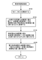
次に、制御装置4が、商用電力系統1において事故(本実施形態では停電)が発生したときの事故時運転制御について図2のフローチャートを参照して説明する。
制御装置4は、商用電力系統1が停電していることを系統停電検出器PTの監視結果に基づいて認識したとき、ステップ100において系統保護用遮断器MC1、MC2を開放して燃料電池3の単独運転を防止する。この瞬間、燃料電池3にとっての電力負荷は余剰電力調節用ヒータ5だけである。次に、ステップ102において制御装置4は、余剰電力調節用ヒータ5の消費電力量が燃料電池3の発電電力量と釣り合うように、余剰電力調節用ヒータ5の消費電力量を調節する。その結果、燃料電池3を商用電力系統1から解列するこの過渡状態において、一般電力負荷器8、9、10、11の消費電力量は、系統保護用遮断器MC2が開放されることによって燃料電池3から解列されたために零となり、且つ、余剰電力調節用ヒータ5の消費電力量は燃料電池3の発電電力量と釣り合った状態となる。但し、このとき制御装置4は、燃料電池3の発電電力量を調節していない。
Next, the operation control at the time of an accident when the controller 4 has an accident (power failure in this embodiment) in the commercial power system 1 will be described with reference to the flowchart of FIG.
When the control device 4 recognizes that the commercial power system 1 is out of power based on the monitoring result of the system power failure detector PT, the control device 4 opens the system protection circuit breakers MC1 and MC2 in
次に、ステップ104において制御装置4は、燃料電池3の発電電力量と余剰電力調節用ヒータ5の消費電力量とを釣り合わせながら、燃料電池3の発電電力量と余剰電力調節用ヒータ5の消費電力量とを共に増大させる。これにより、燃料電池3を最大発電電力量で運転させることが可能となる。
Next, in
そして、ステップ106において制御装置4は、電力負荷装置Lの消費電力量の一部又は全部、つまり余剰電力調節用ヒータ5の消費電力量の一部又は全部を、一般電力負荷器8、9、10、11の消費電力量に切り換えるべく、系統保護用遮断器MC2を投入すると共に一般電力負荷器8、9、10、11の内の特定の一般電力負荷器をオンにし(或いは、CB1、CB2、CB3、CB4の内の特定の容量制限用遮断器を投入し)、且つ、余剰電力調節用ヒータ5の消費電力量を減少させる。そして、制御装置4は、燃料電池3の発電電力量と電力負荷装置Lの消費電力量(余剰電力調節用ヒータ5の消費電力量及びオンにされた一般電力負荷器の消費電力量)とが釣り合うように、カレントトランスCT2を監視している逆潮流防止装置7に対して、その監視結果に基づいて余剰電力調節用ヒータ5の消費電力量を調節させる。制御装置4は、一般電力負荷器8、9、10、11の内の特定の一般電力負荷器をオンするとき、例えば重要負荷であるので優先的に電力供給を行うように予め指定されている一般電力負荷器をオンにする(或いは、対応する容量制限用遮断器を自動投入する)。
In
また、制御装置4は、商用電力系統1において事故が発生していない上記過渡状態の前では、燃料電池3の発電電力量の変動を許容する負荷追従運転などの変動出力運転状態に燃料電池3を制御し、商用電力系統1において事故が発生した後の上記過渡状態の後では、燃料電池3の発電電力量の変動を許容しない定格運転などの一定出力運転状態に燃料電池3を制御している。その結果、上記過渡状態の前では電力余剰が発生しないように発電電力量を変動させながら燃料電池3を効率的に運転させることが可能となり、且つ、上記過渡状態の後では電力不足が発生しないように発電電力量を例えば定格電力で充分に賄うことができる。 Further, before the transient state in which no accident has occurred in the commercial power system 1, the control device 4 enters the fuel cell 3 in a variable output operation state such as a load following operation that allows a variation in the amount of power generated by the fuel cell 3. After the above transient state after an accident has occurred in the commercial power system 1, the fuel cell 3 is controlled to a constant output operation state such as a rated operation that does not allow fluctuations in the amount of power generated by the fuel cell 3. Yes. As a result, it is possible to operate the fuel cell 3 efficiently while changing the amount of generated power so that no power surplus occurs before the transient state, and no power shortage occurs after the transient state. Thus, the amount of generated power can be sufficiently covered by, for example, rated power.
<第2実施形態>
第2実施形態の電力供給システムは、負荷系統2中の燃料電池3と一般電力負荷器8、9、10、11との間に系統保護用遮断器MC2が設けられていない点で、第1実施形態の電力供給システムと異なる。つまり、第1実施形態では系統保護用遮断器MC2を開放している間は燃料電池3から一般電力負荷器8、9、10、11への電力供給を行うことが出来なかったが、第2実施形態の電力供給システムでは、図3に示すように系統保護用遮断器MC2を開放しても燃料電池3から一般電力負荷器8、9、10、11への電力供給を行うことが可能である。以下に、第2実施形態の電力供給システムについて説明するが、第1実施形態と同様の説明は省略する。
Second Embodiment
The power supply system of the second embodiment is the first in that the system protection circuit breaker MC2 is not provided between the fuel cell 3 in the
以下に、制御装置4が、商用電力系統1において事故(本実施形態では停電)が発生したときの事故時運転制御について図3及び図4を参照して説明する。
制御装置4は、商用電力系統1が停電していることを系統停電検出器PTの監視結果に基づいて認識したとき、ステップ200において系統保護用遮断器MC1、MC2を開放して燃料電池3の単独運転を防止する。この瞬間、燃料電池3にとっての電力負荷は余剰電力調節用ヒータ5と一般電力負荷器8、9、10、11である。次に、ステップ202において制御装置4は、電力負荷装置Lの消費電力量(余剰電力調節用ヒータ5の消費電力量及び一般電力負荷8、9、10、11の消費電力量)が燃料電池3の発電電力量と釣り合うように、余剰電力調節用ヒータ5の消費電力量及び一般電力負荷器8、9、10、11の消費電力量を調節する。但し、このとき制御装置4は、燃料電池3の発電電力量を調節していない。
Hereinafter, the operation control at the time of an accident when the control device 4 causes an accident (a power failure in the present embodiment) in the commercial power system 1 will be described with reference to FIGS. 3 and 4.
When the control device 4 recognizes that the commercial power system 1 is out of power based on the monitoring result of the system power failure detector PT, the control device 4 opens the system protection circuit breakers MC1 and MC2 in
次に、ステップ204において制御装置4は、燃料電池3の発電電力量と電力負荷装置Lの消費電力量とを釣り合わせながら、燃料電池3の発電電力量と余剰電力調節用ヒータ5の消費電力量とを共に増大させる。これにより、燃料電池3を最大発電電力量で運転させることが可能となる。
Next, in
そして、ステップ206において制御装置4は、電力負荷装置Lの消費電力量の一部又は全部、つまり余剰電力調節用ヒータ5の消費電力量の一部又は全部を、一般電力負荷器8、9、10、11の消費電力量に切り換えるべく、一般電力負荷器8、9、10、11の内の特定の一般電力負荷器をオンにして(或いは、CB1、CB2、CB3、CB4の内の特定の容量制限用遮断器を投入し)、且つ、余剰電力調節用ヒータ5の消費電力量を減少させる。そして、制御装置4は、燃料電池3の発電電力量と電力負荷装置Lの消費電力量(余剰電力調節用ヒータ5の消費電力量及びオンにされた一般電力負荷器の消費電力量)とが釣り合うように、カレントトランスCT2を監視している逆潮流防止装置7に対して、その監視結果に基づいて余剰電力調節用ヒータ5の消費電力量を調節させている。制御装置4は、一般電力負荷器8、9、10、11の内の特定の一般電力負荷器をオンするとき、例えば重要負荷であるので優先的に電力供給を行うように予め指定されている一般電力負荷器をオンにする(或いは、対応する容量制限用遮断器を自動投入する)。
In
<別実施形態>
<1>
上記実施形態では、制御装置4が一般電力負荷器8、9、10、11を自動的にオンする又は対応する容量制限用遮断器CB1、CB2、CB3、CB4を自動投入する場合について説明したが、一般電力負荷器8、9、10、11の作動又は対応する容量制限用遮断器CB1、CB2、CB3、CB4の投入は手動によって行ってもよい。例えば、制御装置4は、商用電力系統1において停電が発生した後、燃料電池3を商用電力系統1から解列する過渡状態において、上述のステップ104又はステップ204で説明したような燃料電池3の発電電力量と電力負荷装置Lの消費電力量を釣り合わせた状態を維持したまま待機しておく。そして、特定の一般電力負荷器が手動でオンにされたとき又は特定の容量制限用遮断器が手動で投入されたときには、制御装置4は、オンにされた一般電力負荷器の分だけ増大する消費電力量を相殺するために余剰電力調節用ヒータ5の消費電力量を減少させればよい。
<Another embodiment>
<1>
In the above embodiment, the case where the control device 4 automatically turns on the
<2>
上記実施形態では、消費電力量を連続して変化させる調節が可能な余剰電力調節用負荷器の例としてヒータを用いているが、消費電力量を連続して変化させる調節が可能であるならば他の電気機器に置き換えてもよい。
<2>
In the above embodiment, a heater is used as an example of a surplus power adjustment loader capable of continuously changing the power consumption, but if the adjustment can be made to continuously change the power consumption. It may be replaced with other electrical equipment.
<3>
上記第2実施形態では、例えばステップ202及びステップ206のように、燃料電池3の発電電力量と電力負荷装置Lの消費電力量とを釣り合わせるために余剰電力調節用ヒータ5の消費電力量のみを調節していたが、同時に一般電力負荷器8、9、10、11の内の特定の一般電力負荷器をオン又はオフする(或いは、対応する容量制限用遮断器を投入又は開放する)してもよい。
<3>
In the second embodiment, for example, as in
例えば上記ステップ202において、制御装置4が、電力負荷装置Lの消費電力量(余剰電力調節用ヒータ5の消費電力量及び一般電力負荷8、9、10、11の消費電力量)が燃料電池3の発電電力量と釣り合うように、重要負荷では無い特定の一般電力負荷器をオフし、且つ、オフされた一般電力負荷器の消費電力量の分も含めて余剰電力調節用ヒータ5の消費電力量を増大させるように構成してもよい。
また上記ステップ206において、制御装置4が、一般電力負荷器8、9、10、11を適宜オンオフし、オフされた一般電力負荷器の消費電力量の減少分及びオンされた一般電力負荷器の消費電力量の増加分を含めて、電力負荷装置Lの消費電力量(余剰電力調節用ヒータ5の消費電力量及び一般電力負荷8、9、10、11の消費電力量)が燃料電池3の発電電力量と釣り合うように、余剰電力調節用ヒータ5の消費電力量を調節するように構成してもよい。
For example, in the
Further, in
1 商用電力系統
3 燃料電池
4 制御装置
5 余剰電力調節用ヒータ(余剰電力調節用負荷器)
8 一般電力負荷器
9 一般電力負荷器
10 一般電力負荷器
11 一般電力負荷器
L 電力負荷装置
DESCRIPTION OF SYMBOLS 1 Commercial power system 3 Fuel cell 4
8
Claims (4)
前記燃料電池の発電電力量及び前記電力負荷装置の消費電力量を調節可能な制御装置が、前記燃料電池を前記電力系統から解列する過渡状態において、
前記電力負荷装置の消費電力量が前記燃料電池の発電電力量と釣り合うように前記余剰電力調節用負荷器の消費電力量を調節すると共に前記一般電力負荷器の消費電力量を零に調節し、そして、
前記電力負荷装置の消費電力量と前記燃料電池の発電電力量とを釣り合わせながら、前記余剰電力調節用負荷器の消費電力量と前記燃料電池の発電電力量とを共に増大させるように構成されている電力供給システム。 The surplus power adjustment loader capable of continuously changing the power consumption amount and the power consumption amount are intermittently changed from at least one of the power system and the fuel cell connected to the power system. When power is supplied to a power load device provided with an adjustable general power loader and an accident occurs in the power system, the fuel cell is disconnected from the power system. A power supply system,
In a transient state in which the control device capable of adjusting the amount of power generated by the fuel cell and the amount of power consumed by the power load device is disconnected from the power system,
Adjusting the power consumption amount of the surplus power adjustment loader so that the power consumption amount of the power load device is balanced with the power generation amount of the fuel cell, and adjusting the power consumption amount of the general power loader to zero, And
The power consumption device is configured to increase both the power consumption amount of the surplus power adjustment loader and the power generation amount of the fuel cell while balancing the power consumption amount of the power load device and the power generation amount of the fuel cell. Power supply system.
前記燃料電池の発電電力量及び前記電力負荷装置の消費電力量を調節可能な制御装置が、前記燃料電池を前記電力系統から解列する過渡状態において、
前記電力負荷装置の消費電力量が前記燃料電池の発電電力量と釣り合うように前記余剰電力調節用負荷器の消費電力量を調節し、そして、
前記電力負荷装置の消費電力量と前記燃料電池の発電電力量とを釣り合わせながら、前記余剰電力調節用負荷器の消費電力量と前記燃料電池の発電電力量とを共に増大させるように構成されている電力供給システム。 The surplus power adjustment loader capable of continuously changing the power consumption and the power consumption are intermittently changed from at least one of the power system and the fuel cell connected to the power system. When power is supplied to a power load device provided with an adjustable general power loader and an accident occurs in the power system, the fuel cell is disconnected from the power system. A power supply system,
In a transient state in which the control device capable of adjusting the amount of power generated by the fuel cell and the amount of power consumed by the power load device is disconnected from the power system,
Adjusting the power consumption of the surplus power adjustment loader so that the power consumption of the power load device is balanced with the power generation of the fuel cell; and
The power consumption device is configured to increase both the power consumption amount of the surplus power adjustment loader and the power generation amount of the fuel cell while balancing the power consumption amount of the power load device and the power generation amount of the fuel cell. Power supply system.
Priority Applications (1)
| Application Number | Priority Date | Filing Date | Title |
|---|---|---|---|
| JP2004082019A JP4646536B2 (en) | 2004-03-22 | 2004-03-22 | Power supply system |
Applications Claiming Priority (1)
| Application Number | Priority Date | Filing Date | Title |
|---|---|---|---|
| JP2004082019A JP4646536B2 (en) | 2004-03-22 | 2004-03-22 | Power supply system |
Publications (2)
| Publication Number | Publication Date |
|---|---|
| JP2005268149A true JP2005268149A (en) | 2005-09-29 |
| JP4646536B2 JP4646536B2 (en) | 2011-03-09 |
Family
ID=35092458
Family Applications (1)
| Application Number | Title | Priority Date | Filing Date |
|---|---|---|---|
| JP2004082019A Expired - Fee Related JP4646536B2 (en) | 2004-03-22 | 2004-03-22 | Power supply system |
Country Status (1)
| Country | Link |
|---|---|
| JP (1) | JP4646536B2 (en) |
Cited By (23)
| Publication number | Priority date | Publication date | Assignee | Title |
|---|---|---|---|---|
| JP2007207661A (en) * | 2006-02-03 | 2007-08-16 | Nippon Oil Corp | Power supply system having fuel cell system |
| JP2007265778A (en) * | 2006-03-28 | 2007-10-11 | Osaka Gas Co Ltd | Power supply equipment |
| JP2008108666A (en) * | 2006-10-27 | 2008-05-08 | Kyocera Corp | Fuel cell system |
| JP2008135204A (en) * | 2006-11-27 | 2008-06-12 | Mitsubishi Materials Corp | Fuel-cell power generator, and its control method/control program |
| JP2009259578A (en) * | 2008-04-16 | 2009-11-05 | Fuji Electric Holdings Co Ltd | Fuel cell power generation system and its control method |
| JP2009277540A (en) * | 2008-05-15 | 2009-11-26 | Fuji Electric Systems Co Ltd | Control method for fuel cell power generating system, and the fuel power generating system |
| JP2009277585A (en) * | 2008-05-16 | 2009-11-26 | Fuji Electric Systems Co Ltd | Fuel cell power generating system |
| JP2009295398A (en) * | 2008-06-04 | 2009-12-17 | Fuji Electric Systems Co Ltd | Fuel cell power generation device and control method of fuel cell power generation device |
| JP2009295506A (en) * | 2008-06-06 | 2009-12-17 | Fuji Electric Systems Co Ltd | Fuel cell power generation system, its control device, and load amount adjusting method |
| JP2010165640A (en) * | 2009-01-19 | 2010-07-29 | Ebara Corp | Fuel cell unit |
| JP2010238496A (en) * | 2009-03-31 | 2010-10-21 | Jx Nippon Oil & Energy Corp | Fuel cell system |
| JP2012511886A (en) * | 2008-12-09 | 2012-05-24 | ワルトシラ フィンランド オサケユキチュア | Fuel cell device and method for supplying current to an electrical network |
| JP2012214221A (en) * | 2012-05-11 | 2012-11-08 | Jx Nippon Oil & Energy Corp | Safety operation method of emergency time coping type fuel cell system |
| JP2013027072A (en) * | 2011-07-15 | 2013-02-04 | Kyocera Corp | Power control apparatus and power control method |
| WO2013046727A1 (en) * | 2011-09-28 | 2013-04-04 | 京セラ株式会社 | Power supply system and control method for power supply system |
| JP2013143343A (en) * | 2012-01-12 | 2013-07-22 | Toshiba Fuel Cell Power Systems Corp | Fuel cell power generating system and method for operating the same |
| JP2013143212A (en) * | 2012-01-10 | 2013-07-22 | Toshiba Fuel Cell Power Systems Corp | Fuel cell power generation system and operation method thereof |
| JP2013201871A (en) * | 2012-03-26 | 2013-10-03 | Mitsubishi Electric Corp | Power converter |
| JP2013247846A (en) * | 2012-05-29 | 2013-12-09 | Kyocera Corp | Electric power control system, fuel cell, battery, and control method |
| JP2013247844A (en) * | 2012-05-29 | 2013-12-09 | Kyocera Corp | Electric power control system, control device, and control method |
| JP2013247845A (en) * | 2012-05-29 | 2013-12-09 | Kyocera Corp | Electric power control system, fuel cell, and electric power control method |
| JP2014182884A (en) * | 2013-03-18 | 2014-09-29 | Aisin Seiki Co Ltd | Fuel cell system |
| JP2016072106A (en) * | 2014-09-30 | 2016-05-09 | Jx日鉱日石エネルギー株式会社 | Power control method of power supply system, and power supply system |
Citations (4)
| Publication number | Priority date | Publication date | Assignee | Title |
|---|---|---|---|---|
| JPH08236134A (en) * | 1995-02-23 | 1996-09-13 | Mitsubishi Heavy Ind Ltd | Power supply control device for fuel cell |
| JP2002083619A (en) * | 2000-09-07 | 2002-03-22 | Fuji Electric Co Ltd | Control method of fuel cell composite power generating system |
| JP2003197231A (en) * | 2001-12-26 | 2003-07-11 | Toyota Motor Corp | Fuel cell power generation system and its control method |
| JP2005203146A (en) * | 2004-01-13 | 2005-07-28 | Fuji Electric Holdings Co Ltd | Operation method of fuel cell power generating device |
-
2004
- 2004-03-22 JP JP2004082019A patent/JP4646536B2/en not_active Expired - Fee Related
Patent Citations (4)
| Publication number | Priority date | Publication date | Assignee | Title |
|---|---|---|---|---|
| JPH08236134A (en) * | 1995-02-23 | 1996-09-13 | Mitsubishi Heavy Ind Ltd | Power supply control device for fuel cell |
| JP2002083619A (en) * | 2000-09-07 | 2002-03-22 | Fuji Electric Co Ltd | Control method of fuel cell composite power generating system |
| JP2003197231A (en) * | 2001-12-26 | 2003-07-11 | Toyota Motor Corp | Fuel cell power generation system and its control method |
| JP2005203146A (en) * | 2004-01-13 | 2005-07-28 | Fuji Electric Holdings Co Ltd | Operation method of fuel cell power generating device |
Cited By (24)
| Publication number | Priority date | Publication date | Assignee | Title |
|---|---|---|---|---|
| JP2007207661A (en) * | 2006-02-03 | 2007-08-16 | Nippon Oil Corp | Power supply system having fuel cell system |
| JP2007265778A (en) * | 2006-03-28 | 2007-10-11 | Osaka Gas Co Ltd | Power supply equipment |
| JP2008108666A (en) * | 2006-10-27 | 2008-05-08 | Kyocera Corp | Fuel cell system |
| JP2008135204A (en) * | 2006-11-27 | 2008-06-12 | Mitsubishi Materials Corp | Fuel-cell power generator, and its control method/control program |
| JP2009259578A (en) * | 2008-04-16 | 2009-11-05 | Fuji Electric Holdings Co Ltd | Fuel cell power generation system and its control method |
| JP2009277540A (en) * | 2008-05-15 | 2009-11-26 | Fuji Electric Systems Co Ltd | Control method for fuel cell power generating system, and the fuel power generating system |
| JP2009277585A (en) * | 2008-05-16 | 2009-11-26 | Fuji Electric Systems Co Ltd | Fuel cell power generating system |
| JP2009295398A (en) * | 2008-06-04 | 2009-12-17 | Fuji Electric Systems Co Ltd | Fuel cell power generation device and control method of fuel cell power generation device |
| JP2009295506A (en) * | 2008-06-06 | 2009-12-17 | Fuji Electric Systems Co Ltd | Fuel cell power generation system, its control device, and load amount adjusting method |
| JP2012511886A (en) * | 2008-12-09 | 2012-05-24 | ワルトシラ フィンランド オサケユキチュア | Fuel cell device and method for supplying current to an electrical network |
| US8890365B2 (en) | 2008-12-09 | 2014-11-18 | Convion Oy | Fuel cell device and method for feeding electrical current to electrical network |
| JP2010165640A (en) * | 2009-01-19 | 2010-07-29 | Ebara Corp | Fuel cell unit |
| JP2010238496A (en) * | 2009-03-31 | 2010-10-21 | Jx Nippon Oil & Energy Corp | Fuel cell system |
| JP2013027072A (en) * | 2011-07-15 | 2013-02-04 | Kyocera Corp | Power control apparatus and power control method |
| WO2013046727A1 (en) * | 2011-09-28 | 2013-04-04 | 京セラ株式会社 | Power supply system and control method for power supply system |
| JP2013143212A (en) * | 2012-01-10 | 2013-07-22 | Toshiba Fuel Cell Power Systems Corp | Fuel cell power generation system and operation method thereof |
| JP2013143343A (en) * | 2012-01-12 | 2013-07-22 | Toshiba Fuel Cell Power Systems Corp | Fuel cell power generating system and method for operating the same |
| JP2013201871A (en) * | 2012-03-26 | 2013-10-03 | Mitsubishi Electric Corp | Power converter |
| JP2012214221A (en) * | 2012-05-11 | 2012-11-08 | Jx Nippon Oil & Energy Corp | Safety operation method of emergency time coping type fuel cell system |
| JP2013247844A (en) * | 2012-05-29 | 2013-12-09 | Kyocera Corp | Electric power control system, control device, and control method |
| JP2013247845A (en) * | 2012-05-29 | 2013-12-09 | Kyocera Corp | Electric power control system, fuel cell, and electric power control method |
| JP2013247846A (en) * | 2012-05-29 | 2013-12-09 | Kyocera Corp | Electric power control system, fuel cell, battery, and control method |
| JP2014182884A (en) * | 2013-03-18 | 2014-09-29 | Aisin Seiki Co Ltd | Fuel cell system |
| JP2016072106A (en) * | 2014-09-30 | 2016-05-09 | Jx日鉱日石エネルギー株式会社 | Power control method of power supply system, and power supply system |
Also Published As
| Publication number | Publication date |
|---|---|
| JP4646536B2 (en) | 2011-03-09 |
Similar Documents
| Publication | Publication Date | Title |
|---|---|---|
| JP4646536B2 (en) | Power supply system | |
| JP5792824B2 (en) | Power supply system, distributed power supply system, management device, and power supply control method | |
| US20060221523A1 (en) | Control system, method and product for uninterruptible power supply | |
| US8860247B2 (en) | Electric power system and uninterruptible power supply for important load | |
| JP6668991B2 (en) | Power supply device and power supply system | |
| JP2007124811A (en) | Power storage system, route generatiing device and route generation method | |
| JP5296966B2 (en) | Power supply equipment | |
| JP2006271097A (en) | Power supply controller | |
| JP2019198203A (en) | Full load type distribution board and power storage system compatible with the same | |
| JP2019205309A (en) | Power supply system | |
| JP6369803B2 (en) | Power storage device | |
| WO2017026100A1 (en) | Power storage control system, power storage system, power storage control device, charge/discharge control device, and power storage device | |
| JP6995228B2 (en) | Power storage system compatible with full-load distribution boards and full-load distribution boards | |
| JP6529766B2 (en) | Power supply system | |
| JP5368915B2 (en) | Relay and power supply system | |
| JP6109380B2 (en) | Distributed power system | |
| JP2011101536A (en) | Outlet and power distribution system | |
| TWI736202B (en) | On-line uninterruptible power system and operation method thereof | |
| JP6188871B2 (en) | Distributed power system | |
| JP6208613B2 (en) | Power generation system | |
| JP2015133773A (en) | power delivery system | |
| JP6343375B1 (en) | Power system control system | |
| JP2004180402A (en) | Voltage control system for systematically tied dispersed power supply | |
| KR20230103614A (en) | Uninterruptible transforemer replacement apparatus using mobile generator and method | |
| JP5645767B2 (en) | Power control apparatus and power control method |
Legal Events
| Date | Code | Title | Description |
|---|---|---|---|
| A621 | Written request for application examination |
Free format text: JAPANESE INTERMEDIATE CODE: A621 Effective date: 20070126 |
|
| A131 | Notification of reasons for refusal |
Free format text: JAPANESE INTERMEDIATE CODE: A131 Effective date: 20100909 |
|
| A521 | Written amendment |
Free format text: JAPANESE INTERMEDIATE CODE: A523 Effective date: 20101105 |
|
| TRDD | Decision of grant or rejection written | ||
| A01 | Written decision to grant a patent or to grant a registration (utility model) |
Free format text: JAPANESE INTERMEDIATE CODE: A01 Effective date: 20101125 |
|
| A01 | Written decision to grant a patent or to grant a registration (utility model) |
Free format text: JAPANESE INTERMEDIATE CODE: A01 |
|
| A61 | First payment of annual fees (during grant procedure) |
Free format text: JAPANESE INTERMEDIATE CODE: A61 Effective date: 20101207 |
|
| FPAY | Renewal fee payment (event date is renewal date of database) |
Free format text: PAYMENT UNTIL: 20131217 Year of fee payment: 3 |
|
| R150 | Certificate of patent or registration of utility model |
Ref document number: 4646536 Country of ref document: JP Free format text: JAPANESE INTERMEDIATE CODE: R150 Free format text: JAPANESE INTERMEDIATE CODE: R150 |
|
| LAPS | Cancellation because of no payment of annual fees |