JP2005160271A - Hybrid power supply device, motor drive and vehicle - Google Patents
Hybrid power supply device, motor drive and vehicle Download PDFInfo
- Publication number
- JP2005160271A JP2005160271A JP2003398919A JP2003398919A JP2005160271A JP 2005160271 A JP2005160271 A JP 2005160271A JP 2003398919 A JP2003398919 A JP 2003398919A JP 2003398919 A JP2003398919 A JP 2003398919A JP 2005160271 A JP2005160271 A JP 2005160271A
- Authority
- JP
- Japan
- Prior art keywords
- capacitor
- power supply
- supply device
- battery
- motor
- Prior art date
- Legal status (The legal status is an assumption and is not a legal conclusion. Google has not performed a legal analysis and makes no representation as to the accuracy of the status listed.)
- Pending
Links
Images
Classifications
-
- Y—GENERAL TAGGING OF NEW TECHNOLOGICAL DEVELOPMENTS; GENERAL TAGGING OF CROSS-SECTIONAL TECHNOLOGIES SPANNING OVER SEVERAL SECTIONS OF THE IPC; TECHNICAL SUBJECTS COVERED BY FORMER USPC CROSS-REFERENCE ART COLLECTIONS [XRACs] AND DIGESTS
- Y02—TECHNOLOGIES OR APPLICATIONS FOR MITIGATION OR ADAPTATION AGAINST CLIMATE CHANGE
- Y02E—REDUCTION OF GREENHOUSE GAS [GHG] EMISSIONS, RELATED TO ENERGY GENERATION, TRANSMISSION OR DISTRIBUTION
- Y02E60/00—Enabling technologies; Technologies with a potential or indirect contribution to GHG emissions mitigation
- Y02E60/10—Energy storage using batteries
-
- Y—GENERAL TAGGING OF NEW TECHNOLOGICAL DEVELOPMENTS; GENERAL TAGGING OF CROSS-SECTIONAL TECHNOLOGIES SPANNING OVER SEVERAL SECTIONS OF THE IPC; TECHNICAL SUBJECTS COVERED BY FORMER USPC CROSS-REFERENCE ART COLLECTIONS [XRACs] AND DIGESTS
- Y02—TECHNOLOGIES OR APPLICATIONS FOR MITIGATION OR ADAPTATION AGAINST CLIMATE CHANGE
- Y02T—CLIMATE CHANGE MITIGATION TECHNOLOGIES RELATED TO TRANSPORTATION
- Y02T10/00—Road transport of goods or passengers
- Y02T10/60—Other road transportation technologies with climate change mitigation effect
- Y02T10/70—Energy storage systems for electromobility, e.g. batteries
Abstract
Description
本発明は、ハイブリッド電源装置およびモータ駆動装置および車両に関する。 The present invention relates to a hybrid power supply device, a motor drive device, and a vehicle.
従来、例えば駆動源としてのモータの駆動力を駆動輪に伝達して走行する車両に搭載され、並列に接続したキャパシタおよびバッテリからモータへ電力を供給する電源装置が知られている。
そして、このような電源装置として、例えばキャパシタの電圧検出値に応じて、キャパシタとバッテリとの各電流を制御し、キャパシタの電圧を所定範囲内に設定する電源装置が知られている(例えば、特許文献1参照)が知られている。
また、並列に接続した電気二重層コンデンサおよび鉛蓄電池において、相対的に自己放電し易い電気二重層コンデンサの自己放電電流分を鉛蓄電池から補充する電源装置(例えば、特許文献2参照)が知られている。
As such a power supply device, for example, a power supply device that controls each current of the capacitor and the battery according to the detected voltage value of the capacitor and sets the voltage of the capacitor within a predetermined range is known (for example, Patent Document 1) is known.
In addition, there is known a power supply device that replenishes the self-discharge current of the electric double layer capacitor and the lead storage battery connected in parallel from the lead storage battery (for example, see Patent Document 2). ing.
しかしながら、上記従来技術に係る電源装置において、電気二重層コンデンサ等のキャパシタは、鉛蓄電池等のバッテリに比べてエネルギー密度が小さく、自己放電性が高いことから、キャパシタとバッテリとを並列に接続した電源装置の自己放電特性は、主にキャパシタの自己放電特性に支配されてしまい、例えば長期間に亘って充電せずに放置した状態では、バッテリ単体に比べて端子間電圧の低下が大きくなってしまうという問題が生じる。
本発明は上記事情に鑑みてなされたもので、キャパシタとバッテリとを並列に接続したハイブリッド電源装置の蓄電性能を向上させることが可能なハイブリッド電源装置およびモータ駆動装置および車両を提供することを目的とする。
However, in the power supply device according to the above prior art, the capacitor such as an electric double layer capacitor has a smaller energy density and higher self-discharge than a battery such as a lead storage battery, and therefore the capacitor and the battery are connected in parallel. The self-discharge characteristic of the power supply device is mainly governed by the self-discharge characteristic of the capacitor. For example, when left uncharged for a long period of time, the voltage drop between the terminals is larger than that of the battery alone. Problem arises.
The present invention has been made in view of the above circumstances, and an object thereof is to provide a hybrid power supply device, a motor drive device, and a vehicle that can improve the power storage performance of a hybrid power supply device in which a capacitor and a battery are connected in parallel. And
上記課題を解決して係る目的を達成するために、請求項1に記載の本発明のハイブリッド電源装置は、並列に接続されたキャパシタ(例えば、後述する実施の形態でのキャパシタ21)とバッテリ(例えば、後述する実施の形態での鉛蓄電池22)とを備え、電気負荷に電源供給を行うハイブリッド電源装置であって、前記キャパシタと前記バッテリとの接続を切断可能な開閉スイッチ(例えば、後述する実施の形態での開閉スイッチ24)と、前記キャパシタに蓄電されている電気エネルギーを前記バッテリに充電する充電器(例えば、後述する実施の形態での充電器23)とを備え、前記電気負荷および前記ハイブリッド電源装置を備えて構成されるシステムの作動停止時に、前記充電器は前記キャパシタに蓄電されている電気エネルギーを前記バッテリに充電することを特徴としている。
In order to solve the above-mentioned problems and achieve the object, a hybrid power supply device according to the present invention includes a capacitor (for example, a
上記構成のハイブリッド電源装置によれば、システム停止時において、予め、相対的に自己放電し易いキャパシタに蓄電されている電気エネルギーを相対的に自己放電し難いバッテリに充電することで、単にキャパシタとバッテリとを並列に接続した状態で放置する場合に比べて、ハイブリッド電源装置の蓄電性を向上させることができる。 According to the hybrid power supply device configured as described above, when the system is stopped, the electrical energy stored in the capacitor that is relatively easy to self-discharge in advance is charged to the battery that is relatively difficult to self-discharge, thereby simply Compared with the case of leaving the battery connected in parallel, the power storage performance of the hybrid power supply device can be improved.
また、請求項2に記載の本発明のモータ駆動装置は、請求項1に記載のハイブリッド電源装置と、該ハイブリッド電源装置に接続されたインバータ(例えば、後述する実施の形態でのパワードライブユニット14)と、該インバータを介して前記ハイブリッド電源装置に接続されたモータ(例えば、後述する実施の形態でのモータ12)とを備え、前記モータと前記ハイブリッド電源装置との間で電気エネルギーの授受を行うモータ駆動装置であって、前記モータ駆動装置の作動停止時に、前記充電器は前記キャパシタに蓄電されている電気エネルギーを前記バッテリに充電することを特徴としている。
According to a second aspect of the present invention, there is provided a motor drive apparatus according to the present invention, the hybrid power supply apparatus according to the first aspect and an inverter connected to the hybrid power supply apparatus (for example, a
上記構成のモータ駆動装置によれば、モータ駆動装置の停止時において、予め、相対的に自己放電し易いキャパシタに蓄電されている電気エネルギーを相対的に自己放電し難いバッテリに充電することで、単にキャパシタとバッテリとを並列に接続した状態で放置する場合に比べて、ハイブリッド電源装置の蓄電性を向上させることができる。
これにより、モータの再起動時であっても、モータに所望の出力を発生させるための電力を供給することができる。
According to the motor drive device having the above-described configuration, when the motor drive device is stopped, by precharging the battery that is stored in the capacitor that is relatively easy to self-discharge in advance to the battery that is relatively difficult to self-discharge, Compared to the case where the capacitor and the battery are simply connected in parallel, the power storage performance of the hybrid power supply device can be improved.
Thereby, even when the motor is restarted, it is possible to supply electric power for generating a desired output to the motor.
また、請求項3に記載の本発明の車両は、請求項2に記載のモータ駆動装置と、車両の起動または停止を指示する信号を出力する起動停止スイッチ(例えば、後述する実施の形態での起動・停止スイッチ31)とを備え、少なくとも前記モータ駆動装置の駆動力を駆動輪に伝達して走行可能な車両であって、前記起動停止スイッチのOFF時に、前記充電器は前記キャパシタに蓄電されている電気エネルギーを前記バッテリに充電することを特徴としている。 According to a third aspect of the present invention, there is provided a vehicle according to the present invention, the motor drive device according to the second aspect, and a start / stop switch that outputs a signal for instructing start or stop of the vehicle (for example, in an embodiment described later Start / stop switch 31), and a vehicle that can travel by transmitting at least the driving force of the motor drive device to the drive wheels, and when the start / stop switch is OFF, the charger is stored in the capacitor. It is characterized by charging the battery with electrical energy.
上記構成の車両によれば、車両の停止時において、予め、相対的に自己放電し易いキャパシタに蓄電されている電気エネルギーを相対的に自己放電し難いバッテリに充電することで、単にキャパシタとバッテリとを並列に接続した状態で放置する場合に比べて、ハイブリッド電源装置の蓄電性を向上させることができる。
これにより、車両の再起動時であっても、モータに所望の出力を発生させるための電力を供給することができ、車両の走行挙動に運転者の意志を適切に反映させることができる。
According to the vehicle having the above-described configuration, when the vehicle is stopped, the capacitor and the battery are simply charged by charging the electric energy stored in the capacitor that is relatively easy to self-discharge in advance to the battery that is relatively difficult to self-discharge. Can be improved in comparison with the case where the power is left in a state where they are connected in parallel.
Thus, even when the vehicle is restarted, electric power for generating a desired output can be supplied to the motor, and the driver's will can be appropriately reflected in the traveling behavior of the vehicle.
請求項1に記載の本発明のハイブリッド電源装置によれば、単にキャパシタとバッテリとを並列に接続した状態で放置する場合に比べて、ハイブリッド電源装置の蓄電性を向上させることができる。
また、請求項2に記載の本発明のモータ駆動装置によれば、モータの再起動時であっても、モータに所望の出力を発生させるための電力を供給することができる。
また、請求項3に記載の本発明の車両によれば、車両の再起動時であっても、モータに所望の出力を発生させるための電力を供給することができ、車両の走行挙動に運転者の意志を適切に反映させることができる。
According to the hybrid power supply device of the first aspect of the present invention, it is possible to improve the storage performance of the hybrid power supply device as compared with the case where the capacitor and the battery are simply left in parallel.
Further, according to the motor drive device of the present invention described in claim 2, it is possible to supply electric power for generating a desired output to the motor even when the motor is restarted.
Further, according to the vehicle of the present invention described in claim 3, even when the vehicle is restarted, electric power for generating a desired output can be supplied to the motor, and the driving behavior of the vehicle can be improved. Can reflect the will of the person appropriately.
以下、本発明の一実施形態に係るハイブリッド電源装置およびモータ駆動装置および車両ついて添付図面を参照しながら説明する。
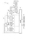
図1はこの発明の実施形態に係るハイブリッド電源装置を備えるパラレルハイブリッド車両1(以下、単に、ハイブリッド車両1と呼ぶ)を示し、内燃機関(ENG)11、モータ(MOT)12、トランスミッション(T/M)13を直列に直結した構造のものである。内燃機関11およびモータ12の両方の駆動力は、例えばオートマチックトランスミッション(AT)あるいはマニュアルトランスミッション(MT)等のトランスミッション13から左右の駆動輪(前輪あるいは後輪)W,W間で駆動力を配分するディファレンシャル(図示略)を介して車両の駆動輪W,Wに伝達される。また、ハイブリッド車両1の減速時に駆動輪W側からモータ12側に駆動力が伝達されると、モータ12は発電機として機能していわゆる回生制動力を発生し、車体の運動エネルギーを電気エネルギーとして回収する。さらに、ハイブリッド車両1の運転状態に応じて、モータ12は内燃機関11の出力によって発電機として駆動され、発電エネルギーを発生するようになっている。
Hereinafter, a hybrid power supply device, a motor drive device, and a vehicle according to an embodiment of the present invention will be described with reference to the accompanying drawings.
FIG. 1 shows a parallel hybrid vehicle 1 (hereinafter simply referred to as a hybrid vehicle 1) provided with a hybrid power supply apparatus according to an embodiment of the present invention, and includes an internal combustion engine (ENG) 11, a motor (MOT) 12, a transmission (T / T M) A structure in which 13 are directly connected in series. The driving force of both the
例えば3相(U相、V相、W相)のDCブラシレスモータ等からなるモータ12は、パワードライブユニット(PDU)14に接続されている。パワードライブユニット14は、例えばトランジスタのスイッチング素子を複数用いてブリッジ接続してなるブリッジ回路を具備するパルス幅変調(PWM)によるPWMインバータを備えて構成されている。
パワードライブユニット14にはモータ12と電力(例えば、モータ12の駆動またはアシスト動作時にモータ12に供給される供給電力や回生動作時にモータ12から出力される回生電力)の授受を行う電源装置15が接続され、パワードライブユニット14は制御装置16からの制御指令を受けてモータ12の駆動及び回生作動を制御する。例えばモータ12の駆動時には、制御装置16から出力されるトルク指令に基づき、電源装置15から出力される直流電力を3相交流電力に変換してモータ12へ供給する。一方、モータ12の回生動作時には、モータ12から出力される3相交流電力を直流電力に変換して電源装置15を充電する。
For example, a
Connected to the
電源装置15は、パワードライブユニット14に対して互いに並列に接続されたキャパシタ21および鉛蓄電池22を備えるハイブリッド電源であって、キャパシタ21は、例えば電気二重層コンデンサや電解コンデンサ等からなる複数のキャパシタセルが直列に接続されて構成されている。さらに、電源装置15は、キャパシタ21および鉛蓄電池22に接続された充電器23と、制御装置16の制御によってキャパシタ21と鉛蓄電池22とを接続または切断可能な開閉スイッチ(開閉SW)24とを備えて構成されている。
そして、充電器23は、制御装置16の制御によって、例えばハイブリッド車両1の停止時等において、キャパシタ21に蓄電されている電気エネルギーを鉛蓄電池22に充電する。
The
The
制御装置16は、内燃機関11の運転状態や、パワードライブユニット14の電力変換動作や、電源装置15の作動状態等を制御する。
このため、制御装置16には、例えばパワープラント(つまり内燃機関11およびモータ12)の状態を検出する各種のセンサ(例えば、内燃機関11の回転数を検出する回転数センサや、モータ12のロータの磁極位置(位相角)を検出する回転角センサ等)から出力される信号およびハイブリッド車両1の状態を検出する各種のセンサ(例えば、速度を検出する車速センサ等)から出力される信号に加えて、ハイブリッド車両1の起動または停止を指示する起動・停止スイッチ(起動・停止SW)31から出力される信号と、運転者のアクセル操作量に係るアクセル開度APを検出するアクセル開度センサ(AP)32から出力される信号が入力されている。
The
For this reason, the
本実施の形態によるハイブリッド電源装置は上記構成を備えており、次に、このハイブリッド電源装置の動作について説明する。 The hybrid power supply device according to the present embodiment has the above-described configuration. Next, the operation of the hybrid power supply device will be described.
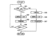
先ず、例えば図2に示すステップS01においては、起動・停止スイッチ31がOFF状態であるか否かを判定する。
この判定結果が「NO」の場合、つまりハイブリッド車両1の作動状態においては、後述するステップS05に進む。
一方、この判定結果が「YES」の場合、つまりハイブリッド車両1の停止状態においては、ステップS02に進む。
ステップS02においては、開閉スイッチ24をOFF状態とし、キャパシタ21と鉛蓄電池22とを切断状態とする。
次に、ステップS03においては、充電器23によって、この時点でキャパシタ21に蓄電されている電気エネルギーを鉛蓄電池22に充電する。
次に、ステップS04においては、キャパシタ21から鉛蓄電池22への充電が完了したか否かを判定する。
この判定結果が「NO」の場合には、上述したステップS01に戻る。
一方、この判定結果が「YES」の場合には、一連の処理を終了する。
First, for example, in step S01 shown in FIG. 2, it is determined whether or not the start / stop switch 31 is in an OFF state.
When the determination result is “NO”, that is, in the operating state of the hybrid vehicle 1, the process proceeds to Step S05 described later.
On the other hand, when the determination result is “YES”, that is, when the hybrid vehicle 1 is stopped, the process proceeds to step S02.
In step S02, the open /
Next, in step S <b> 03, the electric energy stored in the
Next, in step S04, it is determined whether charging from the
If this determination is “NO”, the flow returns to step S 01 described above.
On the other hand, if the determination result is “YES”, the series of processing ends.
また、ステップS05においては、キャパシタ21から鉛蓄電池22への充電動作を停止する。
次に、ステップS06においては、開閉スイッチ24をON状態とし、キャパシタ21と鉛蓄電池22とを接続状態とする。これにより、キャパシタ21と鉛蓄電池22との各蓄電状態が互いに同等の蓄電状態となるように変化する。
次に、ステップS07においては、パワードライブユニット14によってモータ12の駆動及び回生作動の制御を開始し、一連の処理を終了する。
In step S05, the charging operation from the
Next, in step S06, the open /
Next, in step S07, the drive of the
以下に、上述した実施の形態に係るハイブリッド車両1の停止状態におけるハイブリッド電源装置の状態変化の一例を示す実施例について説明する。
この実施例において、キャパシタ21は、例えば5つのキャパシタセル(各キャパシタセルに対して、静電容量が1350F、内部抵抗が2.5mΩ)が直列に接続されて構成されている。また、鉛蓄電池22は、例えば、定格電圧が12Vであって、電池容量が50Ahである。
なお、実施例の電源装置15に対して、電源装置15の代わりに鉛蓄電池22のみを備えた場合を比較例1とし、電源装置15の代わりにキャパシタ21のみを備えた場合を比較例2とし、電源装置15から開閉スイッチ(開閉SW)24および充電器23を省略した場合、つまり単にキャパシタ21と鉛蓄電池22とを並列に接続した場合を比較例3とした。
Hereinafter, examples illustrating an example of a state change of the hybrid power supply apparatus in a stopped state of the hybrid vehicle 1 according to the above-described embodiment will be described.
In this embodiment, the
In addition, the case where only the
そして、実施例および比較例1〜比較例4に対して、先ず、12Vの電圧で5時間に亘って低電圧充電を実行した。
次に、低電圧充電の終了後に、各実施例および比較例1〜比較例4に対して、1秒間連続して出力が出来なくなるまで電流値を徐々に増大させつつ、出力を測定した。この測定結果を、下記表1に示す出力(W)として示した。
次に、各実施例および比較例1〜比較例4に対して、12Vの電圧で5時間に亘って低電圧充電を実行した。
次に、低電圧充電の終了後に、各実施例および比較例1〜比較例4に対して、蓄電電圧が6Vになるまで10Aの電流値で放電を実行し、エネルギーを測定した。この測定結果を、下記表1に示す放電直後のエネルギ放電量1(Wh)として示した。
次に、各実施例および比較例1〜比較例4に対して、12Vの電圧で5時間に亘って低電圧充電を実行した。
次に、実施例に対しては低電圧充電の終了後に上述したステップS02およびステップS03の処理を実行し、この後、各実施例および比較例1〜比較例4に対して、常温下で3ヶ月に亘って放置した。
次に、各実施例および比較例1〜比較例4に対して、蓄電電圧が6Vになるまで10Aの電流値で放電を実行し、エネルギーを測定した。この測定結果を、下記表1に示す3ヶ月経過後のエネルギ放電量2(Wh)として示した。
そして、各実施例および比較例1〜比較例4に対して、3ヶ月経過後のエネルギ放電量2(Wh)を放電直後のエネルギ放電量1(Wh)で除算して得た値をエネルギ維持率(%)とした。下記表1には、各実施例および比較例1〜比較例4に対して、エネルギ維持率(%)と重量(kg)とを示した。
And with respect to an Example and Comparative Example 1- Comparative Example 4, low voltage charge was first performed over 5 hours by the voltage of 12V.
Next, after the end of the low-voltage charging, the output was measured while gradually increasing the current value until the output could not be continuously performed for 1 second for each of Examples and Comparative Examples 1 to 4. The measurement result was shown as output (W) shown in Table 1 below.
Next, low voltage charging was performed for each example and Comparative Examples 1 to 4 at a voltage of 12 V for 5 hours.
Next, after the end of the low voltage charging, discharging was performed at a current value of 10 A until the stored voltage became 6 V for each of Examples and Comparative Examples 1 to 4, and the energy was measured. This measurement result was shown as energy discharge amount 1 (Wh) immediately after the discharge shown in Table 1 below.
Next, low voltage charging was performed for each example and Comparative Examples 1 to 4 at a voltage of 12 V for 5 hours.
Next, after the low voltage charging is completed for the examples, the processes of step S02 and step S03 described above are performed, and thereafter, each example and comparative example 1 to comparative example 4 are subjected to 3 at room temperature. Left for months.
Next, for each of Examples and Comparative Examples 1 to 4, discharging was performed at a current value of 10 A until the storage voltage reached 6 V, and energy was measured. The measurement results are shown as energy discharge amount 2 (Wh) after 3 months shown in Table 1 below.
For each of the examples and Comparative Examples 1 to 4, the value obtained by dividing the energy discharge amount 2 (Wh) after the lapse of 3 months by the energy discharge amount 1 (Wh) immediately after the discharge is maintained. Rate (%). Table 1 below shows the energy retention rate (%) and weight (kg) for each of the examples and Comparative Examples 1 to 4.

上記表1に示す結果から、実施例では、キャパシタ21と鉛蓄電池22とを並列に接続した比較例3と同等の出力を保持しつつ、鉛蓄電池22のみを備える比較例1に対して同等以上のエネルギ維持率を有することがわかる。つまり、鉛蓄電池22のみを備える比較例1と、キャパシタ21のみを備える比較例2との結果からわかるように、鉛蓄電池22に比べてキャパシタ22はエネルギ維持率が極端に小さく、単に、キャパシタ21と鉛蓄電池22とを並列に接続しただけの比較例3では、エネルギ維持率が鉛蓄電池22のみを備える比較例1に比べて低下してしまう。これに対して、実施例のように、システム停止時等において、相対的に自己放電し易いキャパシタ21に蓄電されている電気エネルギーを相対的に自己放電し難い鉛蓄電池22に充電することで、電源装置15のエネルギ維持率を向上させることができることがわかる。
From the results shown in Table 1 above, in the example, while maintaining the output equivalent to that of Comparative Example 3 in which the
上述したように、本実施の形態によるハイブリッド電源装置によれば、並列に接続されたキャパシタ21および鉛蓄電池22を接続または切断可能な開閉スイッチ(開閉SW)24と、キャパシタ21に蓄電されている電気エネルギーを鉛蓄電池22に充電可能な充電器23とを備えて電源装置15を構成し、ハイブリッド車両1の停止時等のシステム停止時において、予め、相対的に自己放電し易いキャパシタ21に蓄電されている電気エネルギーを相対的に自己放電し難い鉛蓄電池22に充電することで、電源装置15のエネルギ維持率を向上させることができる。
さらに、本実施の形態によるハイブリッド電源装置を備えるモータ駆動装置によれば、モータ12の再起動時であっても、モータ12に所望の出力を発生させるための電力を電源装置15からパワードライブユニット14を介して供給することができる。
さらに、本実施の形態によるモータ駆動装置を備える車両によれば、ハイブリッド車両1の再起動時であっても、モータ12に所望の出力を発生させるための電力を電源装置15からパワードライブユニット14を介して供給することができ、ハイブリッド車両1の走行挙動に運転者の意志を適切に反映させることができる。
As described above, according to the hybrid power supply device according to the present embodiment, the
Furthermore, according to the motor drive device including the hybrid power supply device according to the present embodiment, even when the
Furthermore, according to the vehicle including the motor drive device according to the present embodiment, even when the hybrid vehicle 1 is restarted, the
11 内燃機関
12 モータ
14 PDU(インバータ)
22 バッテリ(鉛蓄電池)
21 キャパシタ
23 充電器
24 開閉スイッチ
31 起動・停止スイッチ(起動停止スイッチ)
11
22 battery (lead-acid battery)
21
Claims (3)
前記キャパシタと前記バッテリとの接続を切断可能な開閉スイッチと、
前記キャパシタに蓄電されている電気エネルギーを前記バッテリに充電する充電器とを備え、
前記電気負荷および前記ハイブリッド電源装置を備えて構成されるシステムの作動停止時に、前記充電器は前記キャパシタに蓄電されている電気エネルギーを前記バッテリに充電することを特徴とするハイブリッド電源装置。 A hybrid power supply device that includes a capacitor and a battery connected in parallel and supplies power to an electrical load,
An open / close switch capable of disconnecting the capacitor and the battery;
A charger for charging the battery with electrical energy stored in the capacitor;
The hybrid power supply apparatus according to claim 1, wherein when the system configured to include the electric load and the hybrid power supply apparatus is stopped, the charger charges the battery with the electric energy stored in the capacitor.
前記モータ駆動装置の作動停止時に、前記充電器は前記キャパシタに蓄電されている電気エネルギーを前記バッテリに充電することを特徴とするモータ駆動装置。 A hybrid power supply device according to claim 1, comprising: an inverter connected to the hybrid power supply device; and a motor connected to the hybrid power supply device via the inverter; and between the motor and the hybrid power supply device A motor drive device for transferring electrical energy at
When the operation of the motor driving device is stopped, the charger charges the battery with the electrical energy stored in the capacitor.
前記起動停止スイッチのOFF時に、前記充電器は前記キャパシタに蓄電されている電気エネルギーを前記バッテリに充電することを特徴とする車両。
A motor drive device comprising: the motor drive device according to claim 2; and a start / stop switch that outputs a signal instructing start or stop of the vehicle, wherein the vehicle can travel by transmitting at least the driving force of the motor drive device to the drive wheels. There,
When the start / stop switch is OFF, the charger charges the battery with the electrical energy stored in the capacitor.
Priority Applications (1)
| Application Number | Priority Date | Filing Date | Title |
|---|---|---|---|
| JP2003398919A JP2005160271A (en) | 2003-11-28 | 2003-11-28 | Hybrid power supply device, motor drive and vehicle |
Applications Claiming Priority (1)
| Application Number | Priority Date | Filing Date | Title |
|---|---|---|---|
| JP2003398919A JP2005160271A (en) | 2003-11-28 | 2003-11-28 | Hybrid power supply device, motor drive and vehicle |
Publications (1)
| Publication Number | Publication Date |
|---|---|
| JP2005160271A true JP2005160271A (en) | 2005-06-16 |
Family
ID=34723617
Family Applications (1)
| Application Number | Title | Priority Date | Filing Date |
|---|---|---|---|
| JP2003398919A Pending JP2005160271A (en) | 2003-11-28 | 2003-11-28 | Hybrid power supply device, motor drive and vehicle |
Country Status (1)
| Country | Link |
|---|---|
| JP (1) | JP2005160271A (en) |
Cited By (15)
| Publication number | Priority date | Publication date | Assignee | Title |
|---|---|---|---|---|
| EP1646104A1 (en) * | 2004-09-17 | 2006-04-12 | Robert Bosch Gmbh | device for power supply of a car onboard network |
| JP2006191795A (en) * | 2004-12-28 | 2006-07-20 | Volkswagen Ag <Vw> | Driving method for hybrid energy accumulator, and drive device of hybrid energy accumulator |
| JP2008043103A (en) * | 2006-08-08 | 2008-02-21 | Toyota Motor Corp | Power controller |
| JP2009278822A (en) * | 2008-05-16 | 2009-11-26 | Nanao Corp | Electronic equipment |
| JP2010081762A (en) * | 2008-09-26 | 2010-04-08 | Mazda Motor Corp | Vehicle power supply |
| WO2010150555A1 (en) * | 2009-06-25 | 2010-12-29 | パナソニック株式会社 | Vehicle control system and automobile |
| JP2011514859A (en) * | 2008-02-13 | 2011-05-12 | グツドウイン・ヤング・エル・エル・シー | Hybrid electric vehicle and manufacturing method thereof |
| US9203116B2 (en) | 2006-12-12 | 2015-12-01 | Commonwealth Scientific And Industrial Research Organisation | Energy storage device |
| US9401508B2 (en) | 2009-08-27 | 2016-07-26 | Commonwealth Scientific And Industrial Research Organisation | Electrical storage device and electrode thereof |
| US9450232B2 (en) | 2009-04-23 | 2016-09-20 | Commonwealth Scientific And Industrial Research Organisation | Process for producing negative plate for lead storage battery, and lead storage battery |
| US9508493B2 (en) | 2009-08-27 | 2016-11-29 | The Furukawa Battery Co., Ltd. | Hybrid negative plate for lead-acid storage battery and lead-acid storage battery |
| US9524831B2 (en) | 2009-08-27 | 2016-12-20 | The Furukawa Battery Co., Ltd. | Method for producing hybrid negative plate for lead-acid storage battery and lead-acid storage battery |
| JP2017070077A (en) * | 2015-09-29 | 2017-04-06 | 本田技研工業株式会社 | Power storage device, transportation equipment, and control method |
| US9666860B2 (en) | 2007-03-20 | 2017-05-30 | Commonwealth Scientific And Industrial Research Organisation | Optimised energy storage device having capacitor material on lead based negative electrode |
| US9812703B2 (en) | 2010-12-21 | 2017-11-07 | Commonwealth Scientific And Industrial Research Organisation | Electrode and electrical storage device for lead-acid system |
Citations (4)
| Publication number | Priority date | Publication date | Assignee | Title |
|---|---|---|---|---|
| JPH10164709A (en) * | 1996-11-27 | 1998-06-19 | Isuzu Motors Ltd | Power supply unit and power supply unit for electric vehicle |
| JP2000152419A (en) * | 1998-11-17 | 2000-05-30 | Toyota Motor Corp | Power controller for electric vehicle |
| JP2003102101A (en) * | 2001-09-25 | 2003-04-04 | Suzuki Motor Corp | Power control device for electric vehicle |
| JP2003319502A (en) * | 2002-04-22 | 2003-11-07 | Toyota Motor Corp | Power controller |
-
2003
- 2003-11-28 JP JP2003398919A patent/JP2005160271A/en active Pending
Patent Citations (4)
| Publication number | Priority date | Publication date | Assignee | Title |
|---|---|---|---|---|
| JPH10164709A (en) * | 1996-11-27 | 1998-06-19 | Isuzu Motors Ltd | Power supply unit and power supply unit for electric vehicle |
| JP2000152419A (en) * | 1998-11-17 | 2000-05-30 | Toyota Motor Corp | Power controller for electric vehicle |
| JP2003102101A (en) * | 2001-09-25 | 2003-04-04 | Suzuki Motor Corp | Power control device for electric vehicle |
| JP2003319502A (en) * | 2002-04-22 | 2003-11-07 | Toyota Motor Corp | Power controller |
Cited By (18)
| Publication number | Priority date | Publication date | Assignee | Title |
|---|---|---|---|---|
| EP1646104A1 (en) * | 2004-09-17 | 2006-04-12 | Robert Bosch Gmbh | device for power supply of a car onboard network |
| JP2006191795A (en) * | 2004-12-28 | 2006-07-20 | Volkswagen Ag <Vw> | Driving method for hybrid energy accumulator, and drive device of hybrid energy accumulator |
| JP2008043103A (en) * | 2006-08-08 | 2008-02-21 | Toyota Motor Corp | Power controller |
| US9203116B2 (en) | 2006-12-12 | 2015-12-01 | Commonwealth Scientific And Industrial Research Organisation | Energy storage device |
| US9666860B2 (en) | 2007-03-20 | 2017-05-30 | Commonwealth Scientific And Industrial Research Organisation | Optimised energy storage device having capacitor material on lead based negative electrode |
| JP2011514859A (en) * | 2008-02-13 | 2011-05-12 | グツドウイン・ヤング・エル・エル・シー | Hybrid electric vehicle and manufacturing method thereof |
| JP2015083461A (en) * | 2008-02-13 | 2015-04-30 | グツドウイン・ヤング・エル・エル・シー | Hybrid electric vehicle and methods of production |
| JP2009278822A (en) * | 2008-05-16 | 2009-11-26 | Nanao Corp | Electronic equipment |
| JP4523655B2 (en) * | 2008-05-16 | 2010-08-11 | 株式会社ナナオ | Electronics |
| JP2010081762A (en) * | 2008-09-26 | 2010-04-08 | Mazda Motor Corp | Vehicle power supply |
| US9450232B2 (en) | 2009-04-23 | 2016-09-20 | Commonwealth Scientific And Industrial Research Organisation | Process for producing negative plate for lead storage battery, and lead storage battery |
| JP4932062B2 (en) * | 2009-06-25 | 2012-05-16 | パナソニック株式会社 | Vehicle control system and automobile |
| WO2010150555A1 (en) * | 2009-06-25 | 2010-12-29 | パナソニック株式会社 | Vehicle control system and automobile |
| US9401508B2 (en) | 2009-08-27 | 2016-07-26 | Commonwealth Scientific And Industrial Research Organisation | Electrical storage device and electrode thereof |
| US9508493B2 (en) | 2009-08-27 | 2016-11-29 | The Furukawa Battery Co., Ltd. | Hybrid negative plate for lead-acid storage battery and lead-acid storage battery |
| US9524831B2 (en) | 2009-08-27 | 2016-12-20 | The Furukawa Battery Co., Ltd. | Method for producing hybrid negative plate for lead-acid storage battery and lead-acid storage battery |
| US9812703B2 (en) | 2010-12-21 | 2017-11-07 | Commonwealth Scientific And Industrial Research Organisation | Electrode and electrical storage device for lead-acid system |
| JP2017070077A (en) * | 2015-09-29 | 2017-04-06 | 本田技研工業株式会社 | Power storage device, transportation equipment, and control method |
Similar Documents
| Publication | Publication Date | Title |
|---|---|---|
| JP6462027B2 (en) | Energy storage system for electric or hybrid vehicles | |
| JP5346437B2 (en) | Vehicle propulsion system | |
| JP5011940B2 (en) | Power supply device and vehicle | |
| US8659182B2 (en) | Power supply system and electric powered vehicle including power supply system, and method for controlling power supply system | |
| JP5382238B2 (en) | Hybrid vehicle and control method thereof | |
| JP5772781B2 (en) | Vehicle, power supply system, and control method for power supply system | |
| US8583308B2 (en) | Control device for vehicle | |
| JP6694156B2 (en) | Control device for hybrid vehicle | |
| JP2005160271A (en) | Hybrid power supply device, motor drive and vehicle | |
| US11183856B2 (en) | Battery system, electrically-powered vehicle and control method for electrically-powered vehicle | |
| JP2011087408A (en) | Power supply system of vehicle | |
| JP2009033830A (en) | Controller and control method for electric system, program achieving the method, and recording medium recording the program | |
| JP2011072067A (en) | Power supply system for vehicle and electric vehicle equipped with the same | |
| JP2004023803A (en) | Voltage controller for battery pack | |
| CN105392651A (en) | Vehicle and control method for vehicle | |
| US10857904B2 (en) | Vehicle | |
| JP4496696B2 (en) | Secondary battery temperature rise control device | |
| JP5381360B2 (en) | Power supply | |
| JP2007274840A (en) | Power unit and method of controlling power unit | |
| JP2020198715A (en) | Vehicle drive device | |
| JP2008199807A (en) | Controller for power supply circuit | |
| JP3772875B2 (en) | Control device for hybrid vehicle | |
| JP7344436B2 (en) | vehicle drive system | |
| JP6322417B2 (en) | Voltage fluctuation control device | |
| US20240120851A1 (en) | Electrified vehicle with active discharge of high-voltage bus |
Legal Events
| Date | Code | Title | Description |
|---|---|---|---|
| A621 | Written request for application examination |
Free format text: JAPANESE INTERMEDIATE CODE: A621 Effective date: 20051202 |
|
| A131 | Notification of reasons for refusal |
Free format text: JAPANESE INTERMEDIATE CODE: A131 Effective date: 20080924 |
|
| A521 | Request for written amendment filed |
Free format text: JAPANESE INTERMEDIATE CODE: A523 Effective date: 20081118 |
|
| A131 | Notification of reasons for refusal |
Free format text: JAPANESE INTERMEDIATE CODE: A131 Effective date: 20090630 |
|
| A02 | Decision of refusal |
Free format text: JAPANESE INTERMEDIATE CODE: A02 Effective date: 20091110 |