JP2004226094A - Electronic type watt-hour meter - Google Patents
Electronic type watt-hour meter Download PDFInfo
- Publication number
- JP2004226094A JP2004226094A JP2003010966A JP2003010966A JP2004226094A JP 2004226094 A JP2004226094 A JP 2004226094A JP 2003010966 A JP2003010966 A JP 2003010966A JP 2003010966 A JP2003010966 A JP 2003010966A JP 2004226094 A JP2004226094 A JP 2004226094A
- Authority
- JP
- Japan
- Prior art keywords
- power
- power amount
- phase
- unit
- individual
- Prior art date
- Legal status (The legal status is an assumption and is not a legal conclusion. Google has not performed a legal analysis and makes no representation as to the accuracy of the status listed.)
- Granted
Links
- 230000005856 abnormality Effects 0.000 claims abstract description 37
- 238000003860 storage Methods 0.000 claims description 66
- 230000000694 effects Effects 0.000 claims description 2
- 238000004146 energy storage Methods 0.000 abstract description 5
- 230000002194 synthesizing effect Effects 0.000 abstract description 2
- 238000012545 processing Methods 0.000 description 25
- 238000005259 measurement Methods 0.000 description 17
- 238000001514 detection method Methods 0.000 description 15
- 238000006243 chemical reaction Methods 0.000 description 14
- 238000010586 diagram Methods 0.000 description 12
- 238000004891 communication Methods 0.000 description 10
- 230000007935 neutral effect Effects 0.000 description 6
- 238000005303 weighing Methods 0.000 description 5
- 230000001131 transforming effect Effects 0.000 description 4
- 230000001186 cumulative effect Effects 0.000 description 2
- 230000003111 delayed effect Effects 0.000 description 2
- 238000000034 method Methods 0.000 description 2
- 238000007796 conventional method Methods 0.000 description 1
- 230000001939 inductive effect Effects 0.000 description 1
- 230000010354 integration Effects 0.000 description 1
- 230000014759 maintenance of location Effects 0.000 description 1
Images


Abstract
Description
【0001】
【発明の属する技術分野】
本発明は電子式電力量計に関し、特に計量の信頼性を高める技術に関する。
【0002】
【従来の技術】
従来、電力を計量するために電力量計が使用されている。このような電力量計として、従来から誘導形電力量計が使用されているが、近年は、取付スペースを小さくでき、しかも機械的可動部がないため、取付方向に制約がない電子式電力量計が普及しつつある。
【0003】
図6はこのような電子式電力量計の1つである単相3線式の低圧用電子式電力量計の構成を示すブロック図である。この電子式電力量計は、電源側端子2、負荷側端子3、第1電流検出部(CT1)4、第1電圧検出部(VT1)5、第3電流検出部(CT3)6、第3電圧検出部(VT3)7、計量・制御部8a、表示部9及び通信部10から構成されている。
【0004】
電源側端子2は、電源のニュートラル相(N相)が接続される端子2S、第1相が接続される端子1S及び第3相が接続される端子3Sから構成されている。なお、単相3線式の場合には、第1相の電力と第3相の電力とは位相が異なる訳ではない(単相である)が、本明細書では便宜上、「第1相」及び「第3相」と呼ぶ。同様に、負荷側端子3は、負荷のニュートラル相(N相)に接続される端子2L、第1相に接続される端子1L及び第3相に接続される端子3Lから構成されている。
【0005】
第1電流検出部4は、第1相の電流経路に設けられており、端子1Sから端子1Lに流れる電流を検出し、検出した電流I1を計量・制御部8aに送る。第1電圧検出部5は、N相と第1相との間の電圧を検出し、検出した電圧V1を計量・制御部8aに送る。
【0006】
第3電流検出部6は、第3相の電流経路に設けられており、端子3Sから端子3Lに流れる電流を検出し、検出した電流I3を計量・制御部8aに送る。第3電圧検出部7は、N相と第3相との間の電圧を検出し、検出した電圧V3を計量・制御部8aに送る。
【0007】
計量・制御部8は、第1電流検出部4からの電流I1、第1電圧検出部5からの電圧V1、第3電流検出部6からの電流I3及び第3電圧検出部7からの電圧V3に基づいて電力量を計量する。計量・制御部8aの詳細は後述する。表示部9は、計量・制御部8aで計量された電力量やその他の情報を表示する。通信部10は、遠隔検針や計量・制御部8aへの各種設定を行うために使用される。
【0008】
図7は計量・制御部8aの詳細な構成を示すブロック図である。計量・制御部8aは、第1電力乗算部71、第3電力乗算部72、合成−パルス変換部73及びパルス処理・計量・制御部13から構成されている。
【0009】
第1電力乗算部71は、第1電流検出部4で検出された電流I1と第1電圧検出部5で検出された電圧V1とを乗算することにより第1相の電力を算出し、合成−パルス変換部73に送る。第3電力乗算部72は、第3電流検出部6で検出された電流I3と第3電圧検出部7で検出された電圧V3とを乗算することにより第3相の電力を算出し、合成−パルス変換部73に送る。
【0010】
合成−パルス変換部73は、第1電力乗算部71で算出された電力と、第3電力乗算部72で算出された電力とを合成し、この合成された電力に比例した周波数のパルスに変換する。この合成−パルス変換部73で得られたパルスは、電力量パルスを表すパルス信号として、パルス処理・計量・制御部13に送られる。
【0011】
パルス処理・計量・制御部13は、例えばマイクロコンピュータから構成されており、合成−パルス変換部73から送られてくるパルス信号に含まれる電力量パルスを総合電力量記憶部14に累積加算(積算)する。そして、パルス処理・計量・制御部13は、総合電力量記憶部14に記憶されている総合電力量を表示部9に送る。これにより、総合電力量が表示部9に表示される。また、パルス処理・計量・制御部13は、総合電力量記憶部14に記憶されている総合電力量を通信部10に送る。これにより、通信部10は、総合電力量を電力会社に送信し、電力会社はこの総合電力量に基づいて課金等を行う。
【0012】
なお、従来の電子式電力量計に関連する従来技術として、例えば特許文献1がある。
【0013】
【特許文献1】
特許3112611号(第3頁−6頁、第5図)
【0014】
【発明が解決しようとする課題】
しかしながら、上述した従来の電子式電力量計においては、第1電力乗算部71又は第3電力乗算部72の片方が故障した場合は正しい計量ができなくなるが、電力量計の動作状態は負荷の状態に依存して変動するため、故障の発見が遅れる場合がある。また、電力量計が定格電力内で動作していても、第1相と第3相の電力のバランスが大きく崩れていると片側の相の容量を超える場合があるが、このような異常も発見が遅れてしまう場合がある。
【0015】
本発明は、上記のような問題を解消するためになされたものであり、その課題は、故障や異常が発生した場合に、それらを直ちに発見して計量の信頼性を向上させることができる電子式電力量計を提供することにある。
【0016】
【課題を解決するための手段】
本発明に係る電子式電力量計は、上記課題を達成するために、請求項1の発明は、電源側からの複数線の数より1だけ少ない数だけ設けられ、それぞれが前記複数線の内の基準線と当該線との線間電圧と当該線に流れる電流とを乗算して個別電力量を算出する複数の個別電力量算出部と、前記複数の個別電力量算出部に対応して設けられ、それぞれが当該個別電力量算出部からの前記個別電力量を記憶する複数の個別電力量記憶部と、前記複数の個別電力量算出部からの複数の個別電力量とを合成して得られた総合電力量を記憶する総合電力量記憶部と、前記総合電力量記憶部に記憶されている総合電力量を外部に出力し、且つ前記複数の個別電力量記憶部に記憶されている複数の個別電力量に基づいて異常の有無を判定する制御部とを備えたことを特徴とする。
【0017】
請求項1の発明によれば、総合電力量の他に、複数の個別電力量をも記憶するように構成されているので、これら複数の個別電力量を参照することにより、故障又は異常の有無をいち早く発見することが可能になる。
【0018】
請求項2の発明では、前記制御部は、異常判定情報記憶部を備え、前記複数の個別電力量記憶部に記憶された前記複数の個別電力量の少なくとも1つが、所定範囲以外の値になったときに異常が発生したことを判定し、その旨を前記異常判定情報記憶部に記憶することを特徴とする。
【0019】
請求項2の発明によれば、異常判定情報記憶部を参照することにより、何時でも故障又は異常の有無を知ることができるので、これらをいち早く発見することが可能になる。
【0020】
また、請求項3の発明では、前記複数の個別電力量算出部の各々は、前記個別電力量を該個別電力量に対応する周波数及び符号を有するパルスに変換し、前記複数の個別電力量記憶部は、前記複数の個別電力量算出部から送られてくるパルス数を積算して記憶し、前記総合電力量記憶部は、前記複数の個別電力量算出部から送られてくる複数のパルス数及び符号を考慮して積算して記憶することを特徴とする。
【0021】
更に、請求項4の発明では、前記複数の個別電力量算出部は、前記制御部と一体に形成されることを特徴とする。
【0022】
請求項4の発明によれば、複数の個別電力量算出部及び制御部をワンチップ化することが容易になり、電子式電力量計を小型且つ安価に構成できる。
【0023】
【発明の実施の形態】
以下、本発明の実施の形態に係る電子式電力量計を図面を参照しながら詳細に説明する。
【0024】
(第1の実施の形態)
本発明の第1の実施の形態に係る電子式電力量計は、図6に示した従来の電子式電力量計の中の計量・制御部8aに対して、計量・制御部8の構成が異なる。このため、電子式電力量計の全体の説明は省略するものとし、計量・制御部8の構成及び動作のみを説明する。
【0025】
図1は本発明の第1の実施の形態に係る電子式電力量計の計量・制御部8の構成を示すブロック図である。計量・制御部8は、第1電力−パルス変換部11、第3電力−パルス変換部12、パルス処理・計量・制御部13から構成されている。
【0026】
第1電力−パルス変換部11は、第1電流検出部4からの電流I1と第1電圧検出部5からの電圧V1とを乗算することにより第1相の電力を算出し、更に、この算出された電力を、該電力に比例した周波数を有し且つ正(+)又は負(−)の符号を有するパルスに変換する。この第1電力−パルス変換部11で得られたパルスは、電力量パルスを表すパルス信号として、パルス処理・計量・制御部13に送られる。
【0027】
第3電力−パルス変換部12は、第3電流検出部6からの電流I3と第3電圧検出部7からの電圧V3とを乗算することにより第3相の電力を算出し、更に、この算出された電力を、該電力に比例した周波数を有し且つ正(+)又は負(−)の符号を有するパルスに変換する。この第3電力−パルス変換部12で得られたパルスは、電力量パルスを表すパルス信号として、パルス処理・計量・制御部13に送られる。
【0028】
パルス処理・計量・制御部13は、例えばマイクロコンピュータから構成されており、総合電力量記憶部14、第1相電力量記憶部15、第3相電力量記憶部16及び異常判定情報記憶部17を備えている。このパルス処理・計量・制御部13は、第1電力−パルス変換部11からの電力量パルスと第3電力−パルス変換部12からの電力量パルスとを、符号を考慮して総合電力量記憶部14に累積加算(積算)する。
【0029】
また、パルス処理・計量・制御部13は、第1電力−パルス変換部11からの電力量パルスを第1相電力量記憶部15に累積加算(積算)すると共に、第3電力−パルス変換部12からの電力量パルスを第3相電力量記憶部16に累積加算(積算)する。
【0030】
また、パルス処理・計量・制御部13は、第1相電力量記憶部15に記憶されている値、及び第3相電力量記憶部16に記憶されている値が「0」や「予め設定した値以上の値」になったとき、即ち、所定範囲以外の値になったときに異常が発生したこと判定し、その旨を表す異常判定情報を異常判定情報記憶部17に記憶する。
【0031】
更に、パルス処理・計量・制御部13は、総合電力量記憶部14、第1相電力量記憶部15、第3相電力量記憶部16及び異常判定情報記憶部17に記憶されている内容を表示部9に送る。これにより、総合電力量、第1相電力量、第3相電力量及び異常判定情報が表示部9に表示される。また、パルス処理・計量・制御部13は、総合電力量記憶部14、第1相電力量記憶部15、第3相電力量記憶部16及び異常判定情報記憶部17に記憶されている内容を通信部10に送る。これにより、通信部10は、総合電力量、第1相電力量、第3相電力量及び異常判定情報を電力会社に送信する。
【0032】
以上説明したように、本発明の第1の形態に係る電子式電力量計によれば、第1相電力量と第3相電力量とを合成して積算した総合電力量だけでなく、第1相電力量、第3相電力量及び異常判定情報を記憶しており、適宜、表示部9へ表示したり通信部10を介して電力会社に送ることができる。従って、故障や異常が発生した場合に、需要家又は電力会社において、それらをいち早く発見でき、計量の信頼性を高めることができる。
【0033】
なお、第1電力−パルス変換部11からの電力量パルスと第2電力−パルス変換部12からの電力量パルスを合成して総合電力量を求める場合、累積加算した値が正(+)でも力率の状態や後述する三相3線式などに適用したときに(例えば逆接続のために)片方が負(−)の場合があるので、パルス処理・計量・制御部13は、符号を考慮して電力量パルスを累積加算する処理を行っている。
【0034】
(第2の実施の形態)
本発明の第2の実施の形態は、計器用変成器を使用した変成器付三相3線式の電子式電力量計である。
【0035】
この電子式電力量計は、図2に示すように、計器用変成器32で変圧された電圧及び変流された電流をそれぞれ入力するための電圧端子33と電流端子34とを分離して備えている。計器用変成器32は、電源電圧を変圧することにより生成した第1相の電圧、第2相の電圧及び第3相の電圧、並びに電源電流を変流することにより生成した第1相の電流及び第3相の電流を出力する。
【0036】
電圧端子33は、計器用変成器32からの第1相の変圧された電圧が供給される端子P1、第2相の変圧された電圧が供給される端子P2及び第3相の変圧された電圧が供給される端子P3から構成されている。第1電圧検出部(VT1)5は、第2相と第1相との間の電圧を検出し、検出した電圧V1を計量・制御部8に送る。第3電圧検出部(VT3)7は、第2相と第3相との間の電圧を検出し、検出した電圧V3を計量・制御部8に送る。
【0037】
また、電流端子34は、計器用変成器32からの第1相の変流された電流が入力される端子1S、第1相の変流された電流が出力される端子1L、計器用変成器32からの第3相の変流された電流が入力される端子3S及び第3相の変流された電流が出力される端子3Lから構成されている。
【0038】
第1電流検出部(CT1)4は、第1相の電流経路に設けられており、端子1Sと端子1Lとの間に流れる電流を検出し、検出した電流I1を計量・制御部8に送る。第3電流検出部(CT3)6は、第3相の電流経路に設けられており、端子3Sと端子3Lとの間に流れる電流を検出し、検出した電流I3を計量・制御部8に送る。
【0039】
第1電流検出部4からの電流I1、第1電圧検出部5からの電圧V1、第3電流検出部6からの電流I3及び第3電圧検出部7からの電圧V3が入力される計量・制御部8の構成及び動作は、上述した第1の実施の形態に係る電子式電力量計で説明したものと同じである。
【0040】
このように第2の実施の形態に係る電子式電力量計によれば、電源からの電力が計器用変成器32で降圧及び減流されて第1電圧検出部5、第3電圧検出部7、第1電流検出部4及び第3電流検出部6に供給されるので、高圧用の電子式電力量計として使用することができる。
【0041】
(第3の実施の形態)
本発明の第3の実施の形態は、計器用変成器を使用した変成器付三相4線式の電子式電力量計である。
【0042】
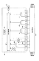
この電子式電力量計は、図3に示すように、計器用変成器42で変圧された電圧、及び変流された電流をそれぞれ入力するための電圧端子43と電流端子44とを分離して備えている。また、上述した第1及び第2の実施の形態の構成に加え、第2電流検出部(CT2)45及び第2電圧検出部(VT2)46を備えている。更に、計量・制御部47は、第2電流検出部45及び第2電圧検出部46からの電流I2及び電圧V2を処理するための第2電力−パルス変換部48を備えている。なお、詳細については、後述する。
【0043】
計器用変成器42は、電源電圧を変圧することにより生成した第1相の電圧、第2相の電圧、第3相の電圧及びニュートラル相の電圧、並びに電源電流を変流することにより生成した第1相の電流、第2相の電流及び第3相の電流を出力する。
【0044】
電圧端子43は、計器用変成器42からの第1相の変圧された電圧が供給される端子P1、第2相の変圧された電圧が供給される端子P2、第3相の変圧された電圧が供給される端子P3及びニュートラル相の電圧が供給される端子P0から構成されている。第1電圧検出部(VT1)5は、ニュートラル相と第1相との間の電圧を検出し、検出した電圧V1を計量・制御部47に送る。第2電圧検出部(VT2)46は、ニュートラル相と第2相との間の電圧を検出し、検出した電圧V2を計量・制御部47に送る。第3電圧検出部(VT3)7は、ニュートラル相と第3相との間の電圧を検出し、検出した電圧V3を計量・制御部47に送る。
【0045】
また、電流端子44は、計器用変成器42からの第1相の変流された電流が入力される端子1S、第1相の変流された電流が出力される端子1L、計器用変成器42からの第2相の変流された電流が入力される端子2S、第2相の変流された電流が出力される端子2L、計器用変成器32からの第3相の変流された電流が入力される端子3S及び第3相の変流された電流が出力される端子3Lから構成されている。
【0046】
第1電流検出部(CT1)4は、第1相の電流経路に設けられており、端子1Sと端子1Lとの間に流れる電流を検出し、検出した電流I1を計量・制御部47に送る。第2電流検出部(CT2)45は、第2相の電流経路に設けられており、端子2Sと端子2Lとの間に流れる電流を検出し、検出した電流I2を計量・制御部47に送る。第3電流検出部(CT3)6は、第3相の電流経路に設けられており、端子3Sと端子3Lとの間に流れる電流を検出し、検出した電流I3を計量・制御部47に送る。
【0047】
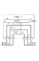
図4は本発明の第3の実施の形態に係る電子式電力量計の計量・制御部47の詳細な構成を示すブロック図である。計量・制御部47は、本発明の第1及び第2の実施の形態に係る電子式電力量計の計量・制御部8に、第2電力−パルス変換部48が追加されると共に、パルス処理・計量・制御部13に第2相電力量記憶部49が追加されたパルス処理・計量・制御部13Aから構成されている。
【0048】
第2電力−パルス変換部48は、第2電流検出部45からの電流I2と第2電圧検出部46からの電圧V2とを乗算することにより第2相の電力を算出し、更に、この算出された電力を、該電力に比例した周波数を有し且つ正(+)又は負(−)の符号を有するパルスに変換する。第2電力−パルス変換部48で得られたパルスは、電力量パルスを表す信号として、パルス処理・計量・制御部13に送られる。
【0049】
パルス処理・計量・制御部13Aは、例えばマイクロコンピュータから構成されており、総合電力量記憶部14、第1相電力量記憶部15、第2相電力量記憶部49、第3相電力量記憶部16及び異常判定情報記憶部17を備えている。パルス処理・計量・制御部13Aは、第1電力−パルス変換部11からの電力量パルス、第2電力−パルス変換部48からの電力量パルス及び第3電力−パルス変換部12からの電力量パルスを、符号を考慮して総合電力量記憶部14に累積加算(積算)する。
【0050】
また、パルス処理・計量・制御部13Aは、第1電力−パルス変換部11からの電力量パルスを第1相電力量記憶部15に累積加算(積算)し、第2電力−パルス変換部48からの電力量パルスを第2相電力量記憶部49に累積加算(積算)し、第3電力−パルス変換部12からの電力量パルスを第3相電力量記憶部16に累積加算(積算)する。
【0051】
また、パルス処理・計量・制御部13Aは、第1相電力量記憶部15に記憶されている値、第2相電力量記憶部49に記憶されている値、又は第3相電力量記憶部16に記憶されている値が「0」や「予め設定した値以上の値」になったとき、異常が発生したこと判定し、その旨をあらわす異常判定情報を異常判定情報記憶部17に記憶する。
【0052】
更に、パルス処理・計量・制御部13Aは、総合電力量記憶部14、第1相電力量記憶部15、第2相電力量記憶部49、第3相電力量記憶部16及び異常判定情報記憶部17に記憶されている内容を表示部9に送る。これにより、総合電力量、第1相電力量、第2相電力量、第3相電力量及び異常判定情報が表示部9に表示される。
【0053】
また、パルス処理・計量・制御部13Aは、総合電力量記憶部14、第1相電力量記憶部15、第2相電力量記憶部49、第3相電力量記憶部16及び異常判定情報記憶部17に記憶されている内容を通信部10に送る。これにより、通信部10は、総合電力量、第1相電力量、第2相電力量、第3相電力量及び異常判定情報を電力会社に送信する。
【0054】
以上説明したように、本発明の第3の実施の形態に係る電子式電力量計によれば、3相交流の各相に故障や異常が発生した場合に、需要家又は電力会社において、それらをいち早く発見でき、計量の信頼性を高めることができる。
【0055】
(第4の実施の形態)
本発明の第4の実施の形態に係る電子式電力量計は、第1及び第2の実施の形態に係る電子式電力量計の計量・制御部8における第1電力−パルス変換部11及び第3電力−パルス変換部12の機能を、電力乗算・計量・制御部61において、ソフトウェア処理で実現したものである。
【0056】
図5は本発明の第4の実施の形態に係る電子式電力量計の計量・制御部8Aの詳細な構成を示すブロック図である。この計量・制御部8Aは、電力乗算・計量・制御部61から構成されている。
【0057】
電力乗算・計量・制御部61は、例えばマイクロコンピュータから構成されており、第1電流検出部4からの電流I1、第1電圧検出部5からの電圧V1、第3電流検出部6からの電流I3及び第3電圧検出部7からの電圧V3が直接に供給される。これら電流I1、電圧V1、電流I3及び電圧V3は、電力乗算・計量・制御部61の内部に設けられたA/D変換器(図示せず)によりデジタルで変換された後、第1及び第2の実施の形態における第1電力−パルス変換部11及び第3電力−パルス変換部12と同等の機能、即ち乗算とパルス変換がソフトウェアの処理によって行われる。
【0058】
以上説明したように、本発明の第4の形態に係る電子式電力量計によれば、第1及び第2の実施の形態における第1電力−パルス変換部11及び第3電力−パルス変換部12と同等の機能、即ち乗算とパルス変換がソフトウェアの処理によって行うようにしたので、部品点数が少なくなり、ワンチップ化に好適である。
【0059】
また、電圧V1、V3又は電流I1、I3の欠落を発見することができ、また、電力量が「0」や「予め設定した値以上の数値」以上になった場合は、勿論、「予め設定した値以上の直流成分値」も判定することが可能になり、これを異常判定情報とすることができる。
【0060】
【発明の効果】
以上説明したように、本発明によれば、故障や異常が発生した場合に、それらを直ちに発見して計量の信頼性を向上させることができる電子式電力量計を提供できる。
【図面の簡単な説明】
【図1】本発明の第1の実施の形態に係る電子式電力量計の計量・制御部の構成を示すブロック図である。
【図2】本発明の第2の実施の形態に係る電子式電力量計の構成を示すブロック図である。
【図3】本発明の第3の実施の形態に係る電子式電力量計の構成を示すブロック図である。
【図4】本発明の第3の実施の形態に係る電子式電力量計の計量・制御部の構成を示すブロック図である。
【図5】本発明の第4の実施の形態に係る電子式電力量計の計量・制御部の構成を示すブロック図である。
【図6】本発明の第1の実施の形態に係る電子式電力量計及び従来の電子式電力量計の構成を示すブロック図である。
【図7】従来の電子式電力量計の計量・制御部の構成を示すブロック図である。
【符号の説明】
2 電源側端子
3 負荷側端子
4 第1電流検出部
5 第1電圧検出部
6 第3電流検出部
7 第3電圧検出部
8 計量・制御部
9 表示部
10 通信部
11 第1電力−パルス変換部
12 第3電力−パルス変換部
13 パルス処理・計量・制御部
14 総合電力量記憶部
15 第1相電力量記憶部
16 第2相電力量記憶部
17 異常判定情報記憶部
32 計器用変成器
33 電圧端子
34 電流端子
42 計器用変成器
43 電圧端子
44 電流端子
45 第2相電流検出部
46 第2相電圧検出部
47 計量・制御部
48 第2電力−パルス変換部
49 第2相電力量記憶部
61 電力乗算・計量・制御部[0001]
TECHNICAL FIELD OF THE INVENTION
The present invention relates to an electronic watt-hour meter, and more particularly to a technique for improving the reliability of measurement.
[0002]
[Prior art]
Conventionally, watt-hour meters have been used to measure power. Conventionally, inductive watt-hour meters have been used as such watt-hour meters. In recent years, electronic watt-hours that can be mounted in a small space and have no mechanical movable parts, so there is no restriction on the mounting direction. Meter is becoming popular.
[0003]
FIG. 6 is a block diagram showing a configuration of a single-phase three-wire low-voltage electronic watt-hour meter, which is one of such electronic watt-hour meters. The electronic wattmeter includes a
[0004]
The power
[0005]
The first
[0006]
The third
[0007]
The measuring /
[0008]
FIG. 7 is a block diagram showing a detailed configuration of the weighing /
[0009]
The first
[0010]
The combining-
[0011]
The pulse processing / metering /
[0012]
Note that, for example,
[0013]
[Patent Document 1]
Patent No. 3112611 (Pages 3-6, Fig. 5)
[0014]
[Problems to be solved by the invention]
However, in the above-mentioned conventional electronic watt-hour meter, if one of the first
[0015]
The present invention has been made to solve the above-described problems, and an object of the present invention is to provide an electronic device capable of immediately detecting a failure or abnormality and improving the reliability of measurement when a failure or abnormality occurs. An object of the present invention is to provide a watt-hour meter.
[0016]
[Means for Solving the Problems]
In order to achieve the above object, the electronic watt-hour meter according to the present invention is arranged such that the number of lines from the power supply side is one smaller than the number of lines from the power supply side, and each of the plurality of lines is one of the plurality of lines. A plurality of individual power amount calculation units for calculating an individual power amount by multiplying a line voltage between the reference line and the line by a current flowing through the line, and provided in correspondence with the plurality of individual power amount calculation units. A plurality of individual power amount storage units each storing the individual power amount from the individual power amount calculation unit and a plurality of individual power amounts from the plurality of individual power amount calculation units. A total power amount storage unit that stores the total power amount, and a plurality of external power amounts that are stored in the total power amount storage unit and output to the external power amount storage unit. A control unit that determines whether there is an abnormality based on the individual electric energy. It is characterized in.
[0017]
According to the first aspect of the present invention, since a plurality of individual power amounts are also stored in addition to the total power amount, by referring to the plurality of individual power amounts, the presence or absence of a failure or abnormality is determined. Can be discovered quickly.
[0018]
In the invention according to
[0019]
According to the second aspect of the present invention, by referring to the abnormality determination information storage unit, it is possible to know at any time whether or not there is a failure or abnormality, so that it is possible to find these immediately.
[0020]
Further, in the invention according to
[0021]
Further, in the invention according to
[0022]
According to the fourth aspect of the present invention, it is easy to integrate the plurality of individual power amount calculation units and the control unit into one chip, and the electronic watt-hour meter can be configured small and inexpensively.
[0023]
BEST MODE FOR CARRYING OUT THE INVENTION
Hereinafter, an electronic watt-hour meter according to an embodiment of the present invention will be described in detail with reference to the drawings.
[0024]
(First Embodiment)
The electronic watt-hour meter according to the first embodiment of the present invention is different from the conventional electronic watt-hour meter shown in FIG. different. Therefore, the entire description of the electronic watt-hour meter will be omitted, and only the configuration and operation of the metering /
[0025]
FIG. 1 is a block diagram showing the configuration of the metering /
[0026]
The first power-to-
[0027]
The third power-to-
[0028]
The pulse processing / metering /
[0029]
In addition, the pulse processing / metering /
[0030]
In addition, the pulse processing / metering /
[0031]
Further, the pulse processing / metering /
[0032]
As described above, according to the electronic watt-hour meter according to the first embodiment of the present invention, not only the total electric energy obtained by synthesizing and integrating the first-phase electric energy and the third-phase electric energy, but also The one-phase power amount, the third-phase power amount, and the abnormality determination information are stored, and can be displayed on the
[0033]
When the total amount of power is obtained by combining the power amount pulse from the first power-to-
[0034]
(Second embodiment)
The second embodiment of the present invention is a three-phase three-wire electronic watt-hour meter with a transformer using a transformer for an instrument.
[0035]
As shown in FIG. 2, this electronic watt-hour meter is provided with a
[0036]
The
[0037]
The
[0038]
The first current detector (CT1) 4 is provided in the first phase current path, detects a current flowing between the terminal 1S and the terminal 1L, and sends the detected current I1 to the metering /
[0039]
Measurement / control in which the current I1 from the first
[0040]
As described above, according to the electronic watt-hour meter according to the second embodiment, the power from the power source is stepped down and reduced by the
[0041]
(Third embodiment)
The third embodiment of the present invention is a three-phase four-wire electronic watt-hour meter with a transformer using an instrument transformer.
[0042]
As shown in FIG. 3, the electronic wattmeter separates a
[0043]
The
[0044]
The
[0045]
The
[0046]
The first current detector (CT1) 4 is provided in the first phase current path, detects a current flowing between the terminal 1S and the terminal 1L, and sends the detected current I1 to the metering /
[0047]
FIG. 4 is a block diagram showing a detailed configuration of the metering /
[0048]
The second power-to-
[0049]
The pulse processing / metering /
[0050]
Further, the pulse processing / metering /
[0051]
Further, the pulse processing / measurement /
[0052]
Further, the pulse processing / metering /
[0053]
The pulse processing / metering /
[0054]
As described above, according to the electronic watt-hour meter according to the third embodiment of the present invention, when a failure or abnormality occurs in each phase of the three-phase AC, the customer or the power company Can be found quickly, and the reliability of weighing can be improved.
[0055]
(Fourth embodiment)
The electronic watt-hour meter according to the fourth embodiment of the present invention includes a first power-
[0056]
FIG. 5 is a block diagram showing a detailed configuration of the metering /
[0057]
The power multiplying / measuring / controlling
[0058]
As described above, according to the electronic watt-hour meter according to the fourth embodiment of the present invention, the first power-
[0059]
In addition, it is possible to detect the lack of the voltages V1 and V3 or the currents I1 and I3, and when the power amount becomes “0” or “a numerical value equal to or more than a preset value”, of course, “ It is also possible to determine a “DC component value that is equal to or greater than the calculated value”, and this can be used as abnormality determination information.
[0060]
【The invention's effect】
As described above, according to the present invention, when a failure or abnormality occurs, it is possible to provide an electronic watt-hour meter that can immediately detect the failure and improve the reliability of measurement.
[Brief description of the drawings]
FIG. 1 is a block diagram illustrating a configuration of a metering / control unit of an electronic watt-hour meter according to a first embodiment of the present invention.
FIG. 2 is a block diagram showing a configuration of an electronic watt-hour meter according to a second embodiment of the present invention.
FIG. 3 is a block diagram showing a configuration of an electronic watt-hour meter according to a third embodiment of the present invention.
FIG. 4 is a block diagram showing a configuration of a metering / control unit of an electronic watt-hour meter according to a third embodiment of the present invention.
FIG. 5 is a block diagram showing a configuration of a metering / control unit of an electronic watt-hour meter according to a fourth embodiment of the present invention.
FIG. 6 is a block diagram showing the configurations of an electronic watt-hour meter according to the first embodiment of the present invention and a conventional electronic watt-hour meter.
FIG. 7 is a block diagram showing a configuration of a metering / control unit of a conventional electronic watt-hour meter.
[Explanation of symbols]
2 power
Claims (4)
前記複数の個別電力量算出部に対応して設けられ、それぞれが当該個別電力量算出部からの前記個別電力量を記憶する複数の個別電力量記憶部と、
前記複数の個別電力量算出部からの複数の個別電力量とを合成して得られた総合電力量を記憶する総合電力量記憶部と、
前記総合電力量記憶部に記憶されている総合電力量を外部に出力し、且つ前記複数の個別電力量記憶部に記憶されている複数の個別電力量に基づいて異常の有無を判定する制御部と、
を備えることを特徴とする電子式電力量計。A number smaller than the number of the plurality of lines from the power supply by one is provided, and each multiplies the voltage between the reference line and the line among the plurality of lines by the current flowing through the line to obtain the individual power amount. A plurality of individual power amount calculation units to calculate;
A plurality of individual power amount storage units provided corresponding to the plurality of individual power amount calculation units, each storing the individual power amount from the individual power amount calculation unit;
A total power storage unit that stores a total power obtained by combining the plurality of individual powers from the plurality of individual power calculation units;
A control unit that outputs the total power amount stored in the total power amount storage unit to the outside, and determines whether there is an abnormality based on the plurality of individual power amounts stored in the plurality of individual power amount storage units When,
An electronic watt-hour meter comprising:
前記複数の個別電力量記憶部に記憶された前記複数の個別電力量の少なくとも1つが、所定範囲以外の値になったときに異常が発生したことを判定し、その旨を前記異常判定情報記憶部に記憶することを特徴とする請求項1記載の電子式電力量計。The control unit includes an abnormality determination information storage unit,
It is determined that an abnormality has occurred when at least one of the plurality of individual power amounts stored in the plurality of individual power amount storage units has a value out of a predetermined range, and the abnormality determination information storage is performed to that effect. The electronic watt-hour meter according to claim 1, wherein the electronic watt-hour is stored in a unit.
前記複数の個別電力量記憶部は、前記複数の個別電力量算出部から送られてくるパルス数を積算して記憶し、
前記総合電力量記憶部は、前記複数の個別電力量算出部から送られてくる複数のパルス数及び符号を考慮して積算して記憶することを特徴とする請求項1記載の電子式電力量計。Each of the plurality of individual power amount calculation unit converts the individual power amount into a pulse having a frequency and a sign corresponding to the individual power amount,
The plurality of individual power amount storage units accumulate and store the number of pulses transmitted from the plurality of individual power amount calculation units,
2. The electronic power amount according to claim 1, wherein the total power amount storage unit accumulates and stores in consideration of a plurality of pulses and codes sent from the plurality of individual power amount calculation units. Total.
Priority Applications (1)
| Application Number | Priority Date | Filing Date | Title |
|---|---|---|---|
| JP2003010966A JP3795462B2 (en) | 2003-01-20 | 2003-01-20 | Electronic energy meter |
Applications Claiming Priority (1)
| Application Number | Priority Date | Filing Date | Title |
|---|---|---|---|
| JP2003010966A JP3795462B2 (en) | 2003-01-20 | 2003-01-20 | Electronic energy meter |
Publications (2)
| Publication Number | Publication Date |
|---|---|
| JP2004226094A true JP2004226094A (en) | 2004-08-12 |
| JP3795462B2 JP3795462B2 (en) | 2006-07-12 |
Family
ID=32900010
Family Applications (1)
| Application Number | Title | Priority Date | Filing Date |
|---|---|---|---|
| JP2003010966A Expired - Lifetime JP3795462B2 (en) | 2003-01-20 | 2003-01-20 | Electronic energy meter |
Country Status (1)
| Country | Link |
|---|---|
| JP (1) | JP3795462B2 (en) |
Cited By (6)
| Publication number | Priority date | Publication date | Assignee | Title |
|---|---|---|---|---|
| JP2007003431A (en) * | 2005-06-27 | 2007-01-11 | Chugoku Electric Power Co Inc:The | Method for measuring electric energy and device and instrument for measuring electric energy |
| JP2009033880A (en) * | 2007-07-27 | 2009-02-12 | Kyushu Electric Power Co Inc | Watt-hour meter having function for blocking electric power line communication signal |
| EP2065715A2 (en) | 2007-11-27 | 2009-06-03 | Kabushiki Kaisha Toshiba | Electricity meter |
| EP2096450A2 (en) | 2008-02-28 | 2009-09-02 | Kabushiki Kaisha Toshiba | Watt-hour meter |
| KR20190086188A (en) * | 2018-01-12 | 2019-07-22 | 고려대학교 산학협력단 | Frequency measuring device including a plurality of voltage sampling devices using low sampling frequency and appliance monitoring system including the same |
| CN113064112A (en) * | 2021-03-23 | 2021-07-02 | 广东电网有限责任公司计量中心 | Service life evaluation method and system for intelligent electric energy meter |
-
2003
- 2003-01-20 JP JP2003010966A patent/JP3795462B2/en not_active Expired - Lifetime
Cited By (12)
| Publication number | Priority date | Publication date | Assignee | Title |
|---|---|---|---|---|
| JP2007003431A (en) * | 2005-06-27 | 2007-01-11 | Chugoku Electric Power Co Inc:The | Method for measuring electric energy and device and instrument for measuring electric energy |
| JP4684022B2 (en) * | 2005-06-27 | 2011-05-18 | 中国電力株式会社 | Electric energy metering method and electric energy metering device |
| JP2009033880A (en) * | 2007-07-27 | 2009-02-12 | Kyushu Electric Power Co Inc | Watt-hour meter having function for blocking electric power line communication signal |
| EP2065715A2 (en) | 2007-11-27 | 2009-06-03 | Kabushiki Kaisha Toshiba | Electricity meter |
| KR101007240B1 (en) * | 2007-11-27 | 2011-01-13 | 도코 도시바 메타 시스템즈 가부시키가이샤 | Electricity meter |
| US7919960B2 (en) | 2007-11-27 | 2011-04-05 | Toshiba Toko Meter Systems Co., Ltd. | Electricity meter capable of minimizing the risk of data destruction from lightning or surge |
| EP2096450A2 (en) | 2008-02-28 | 2009-09-02 | Kabushiki Kaisha Toshiba | Watt-hour meter |
| KR101008895B1 (en) | 2008-02-28 | 2011-01-17 | 도코 도시바 메타 시스템즈 가부시키가이샤 | Watt-hour meter |
| US8433529B2 (en) | 2008-02-28 | 2013-04-30 | Toshiba Toko Meter Systems Co., Ltd. | Watt-hour meter |
| KR20190086188A (en) * | 2018-01-12 | 2019-07-22 | 고려대학교 산학협력단 | Frequency measuring device including a plurality of voltage sampling devices using low sampling frequency and appliance monitoring system including the same |
| KR102004905B1 (en) | 2018-01-12 | 2019-07-29 | 고려대학교 산학협력단 | Frequency measuring device including a plurality of voltage sampling devices using low sampling frequency and appliance monitoring system including the same |
| CN113064112A (en) * | 2021-03-23 | 2021-07-02 | 广东电网有限责任公司计量中心 | Service life evaluation method and system for intelligent electric energy meter |
Also Published As
| Publication number | Publication date |
|---|---|
| JP3795462B2 (en) | 2006-07-12 |
Similar Documents
| Publication | Publication Date | Title |
|---|---|---|
| US6988043B1 (en) | External transformer correction in an electricity meter | |
| US6397155B1 (en) | Method and apparatus for automatically controlled gain switching of monitors | |
| AU676998B2 (en) | Solid state electric power usage meter and method for determining power usage | |
| US6657424B1 (en) | DC load detection in an electric utility meter | |
| US20070007968A1 (en) | Power monitoring system including a wirelessly communicating electrical power transducer | |
| US6385022B1 (en) | Method and apparatus for deriving power system data from configurable source points | |
| JP3160532B2 (en) | Multi-circuit watt-hour meter | |
| JP2003222645A (en) | Multicircuit power measuring device | |
| JP3795462B2 (en) | Electronic energy meter | |
| JP3614048B2 (en) | Energization information measuring device | |
| US11940476B2 (en) | Three-phase power meter monitoring for star and delta configurations | |
| KR200410792Y1 (en) | Electronic energy meter | |
| US7336065B1 (en) | Energy device with an extended dynamic range on current readings | |
| JP2005233879A (en) | Single-phase three-wire system watt-hour meter equipped with line current monitoring function, and line current managing system thereof | |
| JP3323469B2 (en) | Multi-circuit watt-hour meter | |
| JP2003161745A (en) | Method and apparatus for calculation of electrical energy charge | |
| JP3850184B2 (en) | Electricity meter | |
| RU2234707C1 (en) | Device for measuring electrical energy with protection from thefts | |
| JP2004138493A (en) | Electronic watthour meter | |
| KR101144278B1 (en) | Terminal for metering out fit protection | |
| JP2994184B2 (en) | Single-phase three-wire electronic watt-hour meter | |
| KR20040089155A (en) | Electronic Watt-Hour Meter equipped with a prevention apparatus of the miss-connection | |
| JP2004138494A (en) | Electronic watt-hour meter | |
| KR20180022387A (en) | Apparatus and method of detecting connection error | |
| JP2531470B2 (en) | Electronic electricity meter |
Legal Events
| Date | Code | Title | Description |
|---|---|---|---|
| A977 | Report on retrieval |
Free format text: JAPANESE INTERMEDIATE CODE: A971007 Effective date: 20050930 |
|
| A131 | Notification of reasons for refusal |
Free format text: JAPANESE INTERMEDIATE CODE: A131 Effective date: 20051011 |
|
| TRDD | Decision of grant or rejection written | ||
| A01 | Written decision to grant a patent or to grant a registration (utility model) |
Free format text: JAPANESE INTERMEDIATE CODE: A01 Effective date: 20060404 |
|
| A61 | First payment of annual fees (during grant procedure) |
Free format text: JAPANESE INTERMEDIATE CODE: A61 Effective date: 20060412 |
|
| R150 | Certificate of patent or registration of utility model |
Free format text: JAPANESE INTERMEDIATE CODE: R150 Ref document number: 3795462 Country of ref document: JP Free format text: JAPANESE INTERMEDIATE CODE: R150 |
|
| FPAY | Renewal fee payment (event date is renewal date of database) |
Free format text: PAYMENT UNTIL: 20100421 Year of fee payment: 4 |
|
| FPAY | Renewal fee payment (event date is renewal date of database) |
Free format text: PAYMENT UNTIL: 20100421 Year of fee payment: 4 |
|
| S111 | Request for change of ownership or part of ownership |
Free format text: JAPANESE INTERMEDIATE CODE: R313115 |
|
| R371 | Transfer withdrawn |
Free format text: JAPANESE INTERMEDIATE CODE: R371 |
|
| FPAY | Renewal fee payment (event date is renewal date of database) |
Free format text: PAYMENT UNTIL: 20100421 Year of fee payment: 4 |
|
| S111 | Request for change of ownership or part of ownership |
Free format text: JAPANESE INTERMEDIATE CODE: R313115 |
|
| FPAY | Renewal fee payment (event date is renewal date of database) |
Free format text: PAYMENT UNTIL: 20100421 Year of fee payment: 4 |
|
| R350 | Written notification of registration of transfer |
Free format text: JAPANESE INTERMEDIATE CODE: R350 |
|
| FPAY | Renewal fee payment (event date is renewal date of database) |
Free format text: PAYMENT UNTIL: 20110421 Year of fee payment: 5 |
|
| R250 | Receipt of annual fees |
Free format text: JAPANESE INTERMEDIATE CODE: R250 |
|
| FPAY | Renewal fee payment (event date is renewal date of database) |
Free format text: PAYMENT UNTIL: 20110421 Year of fee payment: 5 |
|
| RD03 | Notification of appointment of power of attorney |
Free format text: JAPANESE INTERMEDIATE CODE: R3D03 |
|
| R250 | Receipt of annual fees |
Free format text: JAPANESE INTERMEDIATE CODE: R250 |
|
| FPAY | Renewal fee payment (event date is renewal date of database) |
Free format text: PAYMENT UNTIL: 20120421 Year of fee payment: 6 |
|
| R250 | Receipt of annual fees |
Free format text: JAPANESE INTERMEDIATE CODE: R250 |
|
| FPAY | Renewal fee payment (event date is renewal date of database) |
Free format text: PAYMENT UNTIL: 20130421 Year of fee payment: 7 |
|
| S111 | Request for change of ownership or part of ownership |
Free format text: JAPANESE INTERMEDIATE CODE: R313117 |
|
| FPAY | Renewal fee payment (event date is renewal date of database) |
Free format text: PAYMENT UNTIL: 20130421 Year of fee payment: 7 |
|
| R350 | Written notification of registration of transfer |
Free format text: JAPANESE INTERMEDIATE CODE: R350 |
|
| FPAY | Renewal fee payment (event date is renewal date of database) |
Free format text: PAYMENT UNTIL: 20130421 Year of fee payment: 7 |
|
| FPAY | Renewal fee payment (event date is renewal date of database) |
Free format text: PAYMENT UNTIL: 20140421 Year of fee payment: 8 |
|
| R250 | Receipt of annual fees |
Free format text: JAPANESE INTERMEDIATE CODE: R250 |
|
| R250 | Receipt of annual fees |
Free format text: JAPANESE INTERMEDIATE CODE: R250 |
|
| R250 | Receipt of annual fees |
Free format text: JAPANESE INTERMEDIATE CODE: R250 |
|
| R250 | Receipt of annual fees |
Free format text: JAPANESE INTERMEDIATE CODE: R250 |
|
| S531 | Written request for registration of change of domicile |
Free format text: JAPANESE INTERMEDIATE CODE: R313531 |
|
| R350 | Written notification of registration of transfer |
Free format text: JAPANESE INTERMEDIATE CODE: R350 |
|
| R250 | Receipt of annual fees |
Free format text: JAPANESE INTERMEDIATE CODE: R250 |
|
| R250 | Receipt of annual fees |
Free format text: JAPANESE INTERMEDIATE CODE: R250 |
|
| R250 | Receipt of annual fees |
Free format text: JAPANESE INTERMEDIATE CODE: R250 |
|
| R250 | Receipt of annual fees |
Free format text: JAPANESE INTERMEDIATE CODE: R250 |
|
| R250 | Receipt of annual fees |
Free format text: JAPANESE INTERMEDIATE CODE: R250 |
|
| R250 | Receipt of annual fees |
Free format text: JAPANESE INTERMEDIATE CODE: R250 |
|
| EXPY | Cancellation because of completion of term |