EP3905480A1 - A charging system for electric vehicles - Google Patents
A charging system for electric vehicles Download PDFInfo
- Publication number
- EP3905480A1 EP3905480A1 EP20172514.0A EP20172514A EP3905480A1 EP 3905480 A1 EP3905480 A1 EP 3905480A1 EP 20172514 A EP20172514 A EP 20172514A EP 3905480 A1 EP3905480 A1 EP 3905480A1
- Authority
- EP
- European Patent Office
- Prior art keywords
- voltage
- charging
- signal
- medium
- low
- Prior art date
- Legal status (The legal status is an assumption and is not a legal conclusion. Google has not performed a legal analysis and makes no representation as to the accuracy of the status listed.)
- Pending
Links
Images


Classifications
-
- H—ELECTRICITY
- H02—GENERATION; CONVERSION OR DISTRIBUTION OF ELECTRIC POWER
- H02J—CIRCUIT ARRANGEMENTS OR SYSTEMS FOR SUPPLYING OR DISTRIBUTING ELECTRIC POWER; SYSTEMS FOR STORING ELECTRIC ENERGY
- H02J7/00—Circuit arrangements for charging or depolarising batteries or for supplying loads from batteries
- H02J7/02—Circuit arrangements for charging or depolarising batteries or for supplying loads from batteries for charging batteries from ac mains by converters
-
- B—PERFORMING OPERATIONS; TRANSPORTING
- B60—VEHICLES IN GENERAL
- B60L—PROPULSION OF ELECTRICALLY-PROPELLED VEHICLES; SUPPLYING ELECTRIC POWER FOR AUXILIARY EQUIPMENT OF ELECTRICALLY-PROPELLED VEHICLES; ELECTRODYNAMIC BRAKE SYSTEMS FOR VEHICLES IN GENERAL; MAGNETIC SUSPENSION OR LEVITATION FOR VEHICLES; MONITORING OPERATING VARIABLES OF ELECTRICALLY-PROPELLED VEHICLES; ELECTRIC SAFETY DEVICES FOR ELECTRICALLY-PROPELLED VEHICLES
- B60L53/00—Methods of charging batteries, specially adapted for electric vehicles; Charging stations or on-board charging equipment therefor; Exchange of energy storage elements in electric vehicles
-
- H—ELECTRICITY
- H02—GENERATION; CONVERSION OR DISTRIBUTION OF ELECTRIC POWER
- H02J—CIRCUIT ARRANGEMENTS OR SYSTEMS FOR SUPPLYING OR DISTRIBUTING ELECTRIC POWER; SYSTEMS FOR STORING ELECTRIC ENERGY
- H02J1/00—Circuit arrangements for dc mains or dc distribution networks
-
- H—ELECTRICITY
- H02—GENERATION; CONVERSION OR DISTRIBUTION OF ELECTRIC POWER
- H02J—CIRCUIT ARRANGEMENTS OR SYSTEMS FOR SUPPLYING OR DISTRIBUTING ELECTRIC POWER; SYSTEMS FOR STORING ELECTRIC ENERGY
- H02J3/00—Circuit arrangements for ac mains or ac distribution networks
-
- H—ELECTRICITY
- H02—GENERATION; CONVERSION OR DISTRIBUTION OF ELECTRIC POWER
- H02J—CIRCUIT ARRANGEMENTS OR SYSTEMS FOR SUPPLYING OR DISTRIBUTING ELECTRIC POWER; SYSTEMS FOR STORING ELECTRIC ENERGY
- H02J4/00—Circuit arrangements for mains or distribution networks not specified as ac or dc
-
- H—ELECTRICITY
- H02—GENERATION; CONVERSION OR DISTRIBUTION OF ELECTRIC POWER
- H02J—CIRCUIT ARRANGEMENTS OR SYSTEMS FOR SUPPLYING OR DISTRIBUTING ELECTRIC POWER; SYSTEMS FOR STORING ELECTRIC ENERGY
- H02J5/00—Circuit arrangements for transfer of electric power between ac networks and dc networks
-
- H—ELECTRICITY
- H02—GENERATION; CONVERSION OR DISTRIBUTION OF ELECTRIC POWER
- H02M—APPARATUS FOR CONVERSION BETWEEN AC AND AC, BETWEEN AC AND DC, OR BETWEEN DC AND DC, AND FOR USE WITH MAINS OR SIMILAR POWER SUPPLY SYSTEMS; CONVERSION OF DC OR AC INPUT POWER INTO SURGE OUTPUT POWER; CONTROL OR REGULATION THEREOF
- H02M3/00—Conversion of dc power input into dc power output
- H02M3/22—Conversion of dc power input into dc power output with intermediate conversion into ac
- H02M3/24—Conversion of dc power input into dc power output with intermediate conversion into ac by static converters
- H02M3/28—Conversion of dc power input into dc power output with intermediate conversion into ac by static converters using discharge tubes with control electrode or semiconductor devices with control electrode to produce the intermediate ac
- H02M3/325—Conversion of dc power input into dc power output with intermediate conversion into ac by static converters using discharge tubes with control electrode or semiconductor devices with control electrode to produce the intermediate ac using devices of a triode or a transistor type requiring continuous application of a control signal
- H02M3/335—Conversion of dc power input into dc power output with intermediate conversion into ac by static converters using discharge tubes with control electrode or semiconductor devices with control electrode to produce the intermediate ac using devices of a triode or a transistor type requiring continuous application of a control signal using semiconductor devices only
- H02M3/33569—Conversion of dc power input into dc power output with intermediate conversion into ac by static converters using discharge tubes with control electrode or semiconductor devices with control electrode to produce the intermediate ac using devices of a triode or a transistor type requiring continuous application of a control signal using semiconductor devices only having several active switching elements
-
- B—PERFORMING OPERATIONS; TRANSPORTING
- B60—VEHICLES IN GENERAL
- B60L—PROPULSION OF ELECTRICALLY-PROPELLED VEHICLES; SUPPLYING ELECTRIC POWER FOR AUXILIARY EQUIPMENT OF ELECTRICALLY-PROPELLED VEHICLES; ELECTRODYNAMIC BRAKE SYSTEMS FOR VEHICLES IN GENERAL; MAGNETIC SUSPENSION OR LEVITATION FOR VEHICLES; MONITORING OPERATING VARIABLES OF ELECTRICALLY-PROPELLED VEHICLES; ELECTRIC SAFETY DEVICES FOR ELECTRICALLY-PROPELLED VEHICLES
- B60L2210/00—Converter types
- B60L2210/30—AC to DC converters
-
- B—PERFORMING OPERATIONS; TRANSPORTING
- B60—VEHICLES IN GENERAL
- B60L—PROPULSION OF ELECTRICALLY-PROPELLED VEHICLES; SUPPLYING ELECTRIC POWER FOR AUXILIARY EQUIPMENT OF ELECTRICALLY-PROPELLED VEHICLES; ELECTRODYNAMIC BRAKE SYSTEMS FOR VEHICLES IN GENERAL; MAGNETIC SUSPENSION OR LEVITATION FOR VEHICLES; MONITORING OPERATING VARIABLES OF ELECTRICALLY-PROPELLED VEHICLES; ELECTRIC SAFETY DEVICES FOR ELECTRICALLY-PROPELLED VEHICLES
- B60L2210/00—Converter types
- B60L2210/40—DC to AC converters
-
- H—ELECTRICITY
- H02—GENERATION; CONVERSION OR DISTRIBUTION OF ELECTRIC POWER
- H02J—CIRCUIT ARRANGEMENTS OR SYSTEMS FOR SUPPLYING OR DISTRIBUTING ELECTRIC POWER; SYSTEMS FOR STORING ELECTRIC ENERGY
- H02J2207/00—Indexing scheme relating to details of circuit arrangements for charging or depolarising batteries or for supplying loads from batteries
- H02J2207/20—Charging or discharging characterised by the power electronics converter
-
- Y—GENERAL TAGGING OF NEW TECHNOLOGICAL DEVELOPMENTS; GENERAL TAGGING OF CROSS-SECTIONAL TECHNOLOGIES SPANNING OVER SEVERAL SECTIONS OF THE IPC; TECHNICAL SUBJECTS COVERED BY FORMER USPC CROSS-REFERENCE ART COLLECTIONS [XRACs] AND DIGESTS
- Y02—TECHNOLOGIES OR APPLICATIONS FOR MITIGATION OR ADAPTATION AGAINST CLIMATE CHANGE
- Y02T—CLIMATE CHANGE MITIGATION TECHNOLOGIES RELATED TO TRANSPORTATION
- Y02T10/00—Road transport of goods or passengers
- Y02T10/60—Other road transportation technologies with climate change mitigation effect
- Y02T10/70—Energy storage systems for electromobility, e.g. batteries
-
- Y—GENERAL TAGGING OF NEW TECHNOLOGICAL DEVELOPMENTS; GENERAL TAGGING OF CROSS-SECTIONAL TECHNOLOGIES SPANNING OVER SEVERAL SECTIONS OF THE IPC; TECHNICAL SUBJECTS COVERED BY FORMER USPC CROSS-REFERENCE ART COLLECTIONS [XRACs] AND DIGESTS
- Y02—TECHNOLOGIES OR APPLICATIONS FOR MITIGATION OR ADAPTATION AGAINST CLIMATE CHANGE
- Y02T—CLIMATE CHANGE MITIGATION TECHNOLOGIES RELATED TO TRANSPORTATION
- Y02T10/00—Road transport of goods or passengers
- Y02T10/60—Other road transportation technologies with climate change mitigation effect
- Y02T10/7072—Electromobility specific charging systems or methods for batteries, ultracapacitors, supercapacitors or double-layer capacitors
-
- Y—GENERAL TAGGING OF NEW TECHNOLOGICAL DEVELOPMENTS; GENERAL TAGGING OF CROSS-SECTIONAL TECHNOLOGIES SPANNING OVER SEVERAL SECTIONS OF THE IPC; TECHNICAL SUBJECTS COVERED BY FORMER USPC CROSS-REFERENCE ART COLLECTIONS [XRACs] AND DIGESTS
- Y02—TECHNOLOGIES OR APPLICATIONS FOR MITIGATION OR ADAPTATION AGAINST CLIMATE CHANGE
- Y02T—CLIMATE CHANGE MITIGATION TECHNOLOGIES RELATED TO TRANSPORTATION
- Y02T90/00—Enabling technologies or technologies with a potential or indirect contribution to GHG emissions mitigation
- Y02T90/10—Technologies relating to charging of electric vehicles
- Y02T90/12—Electric charging stations
-
- Y—GENERAL TAGGING OF NEW TECHNOLOGICAL DEVELOPMENTS; GENERAL TAGGING OF CROSS-SECTIONAL TECHNOLOGIES SPANNING OVER SEVERAL SECTIONS OF THE IPC; TECHNICAL SUBJECTS COVERED BY FORMER USPC CROSS-REFERENCE ART COLLECTIONS [XRACs] AND DIGESTS
- Y02—TECHNOLOGIES OR APPLICATIONS FOR MITIGATION OR ADAPTATION AGAINST CLIMATE CHANGE
- Y02T—CLIMATE CHANGE MITIGATION TECHNOLOGIES RELATED TO TRANSPORTATION
- Y02T90/00—Enabling technologies or technologies with a potential or indirect contribution to GHG emissions mitigation
- Y02T90/10—Technologies relating to charging of electric vehicles
- Y02T90/14—Plug-in electric vehicles
Definitions
- the invention relates to the field of power supplies, particularly for a charging system, e.g. for electric vehicles.
- the invention further relates to a method and to a use of a power supply.
- Charging systems for electric vehicles require high power levels. For instance, for a range of about 300 to 400 km for the charged vehicle, a charging pole may require about 350 kW. In many cases, EV charging stations have more than one charging pole. This may result in bulky frontends for the system that feeds the charging pole.
- the charging system comprises a LIT-based rectifier (LIT: Line Interphase Transformer), configured for connecting an input of the LIT-based rectifier to an AC medium-voltage power signal and for outputting a medium-voltage DC-signal; a modular DC/DC converter with large step-down gain, configured for transforming the medium-voltage DC-signal into a medium-voltage HF-AC-signal; and a medium-frequency transformer, MFT, configured for transforming the medium-voltage HF-AC-signal into a low-voltage HF-AC-signal for the at least one charging box (HF: high frequency).
- LIT Line Interphase Transformer
- the low-voltage power signal of the EV charging stations may have a voltage, ranging from about 400 V to 1000 V, or about 230 V, or about 110 V. This voltage or the low-voltage range may be the output-voltage of the charging box.
- the output-voltage of the charging box may be variable, e.g. depending on the charging needs.
- the input-voltage of the charging box may be a fixed voltage, e.g. ranging from about 400 V to 1000 V.
- Said input-voltage (and/or the power supply system) may be used for different and/or further types of power supplies with similar power demand, for instance for power data-centres with a plurality of computing servers, and/or for so-called "drives", i.e. electrical machines connected via converter, e.g. in manufacturing centres.
- the drives may be implemented as electric motors, for instance as low-voltage motors or, after a transformation, as medium-voltage motors, and/or as other machines.
- the power per EV charging station to be delivered may be about 350 kW, particularly for fast charging.
- EV charging stations may have several charging poles. Not every charging pole in one site may need to deliver this ("full") power, not all cars may be charged at the same time.
- an EV charging station may have a power rating of around 2 MW.
- the AC medium-voltage power signal which serves as an input for the LIT-based rectifier, may have a so-called medium-voltage (MV) of about 10 kV - 30 kV.
- the power signal may be part of a medium-voltage grid.
- the AC medium-voltage power signal may have, e.g., 3 phases, with AC of low frequency, for example of 50 or 60 Hz.
- the LIT-based rectifier may comprise a line-side interphase transformer - e.g. designed as a 12-pulse LIT or 18-pulse-LIT - and a multi-pulse diode rectifier.
- the rectifier is configured to output a medium-voltage DC-signal. There may be no galvanic insulation from the medium-voltage power signal.
- the DC-signal may provide an uncontrolled MV DC-link.
- the modular DC/DC converter with large step-down gain may be configured to deliver the MV HF-AC-signal with a frequency of multiple times the mains frequency, for example of about 5 kHz - 20 kHz.
- One implementation of a modular DC/DC converter with large step-down gain may be a multilevel flying capacitor inverter.
- the MV HF-AC-signal is fed into the Medium-Frequency Transformer, MFT, configured for transforming the medium-voltage HF-AC-signal into the low-voltage HF-AC-signal, which may be an input for the at least one charging box and/or for the charging pole.
- MFT Medium-Frequency Transformer
- the MFT may provide both a galvanic insulation from the medium-voltage power signal and a voltage adaption to the low-voltage HF-AC-signal.
- the galvanic insulation from the MV grid may be a legal requirement.
- the charging boxes may comprise means for a galvanic insulation between the charging poles.
- the charging system a simple system at low manufacturing-cost. Nevertheless, it can provide high power, due to its connection to an AC medium-voltage power signal or a medium-voltage grid. Moreover, the charging system is of small-size and low losses, for instance by avoiding large and expensive 50 Hz transformers.
- the charging system further comprises an inductor, configured for a filtering connection between each phase of the AC medium-voltage power signal and each input of the LIT-based rectifier.
- the inductor which connects MV grid and LIT-based rectifier, is designed to reduce the current harmonics. In at least some countries, this may be a legal and/or a standard requirement, e.g. to comply with relevant MV grid standards, e.g. with IEEE 519 or IEC 61000-3-6.
- said requirements may be fulfilled without complex and expensive active frontends to the MV grid, thus leading to a simpler design, lower manufacturing-cost, and/or reducing maintenance efforts.
- the LIT-based rectifier comprises a multi-pulse LIT with a pulse number of 12, of 18, of 24, or of higher than 24. This advantageously leads to a reduction of the harmonics, thus reducing the need for an inductor as described above and/or below and/or reducing its impedance. This further contributes to an efficient power supply system, with quite low complexity in design and manufacturing.
- the LIT-based rectifier comprises a line-side interphase transformer, LIT, and a multi-pulse diode rectifier.
- LIT line-side interphase transformer
- the multi-pulse diode rectifier may be realized as a parallel-connected diode rectifier (see, e.g., the figures below).
- the multi-pulse diode rectifier may be realized as a series-connected diode rectifier, where the "DC-ends" of the diode rectifier bridges are connected in series.
- each one of the diodes of the multi-pulse diode rectifier is realized as a thyristor. This advantageously provides a fast and simple breaking capability, e.g. in case of an overcurrent.
- the charging system further comprises a plurality of charging boxes, wherein each one of the plurality of charging boxes comprises a low-voltage MFT, a low-voltage AC/DC-converter, and a charging pole for charging electric vehicles.
- the plurality of charging boxes may comprise, e.g., two, four, six, a dozen and/or more charging boxes. This design of ensures each one of the plurality of charging boxes ensures a galvanic separation or insulation between the charging poles, which may be a legal and/or standard requirement in at least some countries.
- the charging system or power supply system may be connected to other types of power supplies and/or bridges or control modules.
- Said power supplies, bridges, and/or control modules may be used for supplying a plurality of servers or other computer in a data-centre, a site for server-clouds, other computing applications, and/or for a plurality of electric motors.
- An aspect relates to a method for transforming an AC medium-voltage power signal into a low-voltage power signal for at least one charging box for charging electric vehicles.
- the method comprising the steps of:
- This method advantageously provides an easy-to-handle process to deliver high power to a plurality of charging boxes and/or charging poles for charging electric vehicles. Moreover, this concept contributes to a highly scalable design of charging poles, particularly for fast charging.
- the method further comprises the step of filtering, by means of an inductor, each phase of the AC medium-voltage power signal from each input of the LIT-based rectifier.
- An aspect relates to a charging system described above and/or below for delivering energy to a charging box and/or to a charging pole for charging electric vehicles.
- the low-voltage HF-AC-signal (59) is connected to a DC voltage bus for low-voltage power distribution.
- the low-voltage HF-AC-signal is connected to a AC/DC transformer that outputs the LV DC signal to the DC voltage bus.
- the AC/DC transformer may be a rectifier, an AC/DC, and/or a similar component.
- the DC voltage bus advantageously provides a kind of multipurpose interface, which may serve as a basis for a plurality of use-cases and/or devices to connect to the DC voltage bus.
- An aspect relates to a use of a charging system described above and/or below for delivering energy to a charging box, to a charging pole for charging electric vehicles, to a data-centre, and/or to low-voltage drives.
- the charging system or power supply system may be used in a data-centre to power, e.g., a plurality of servers, for instance a server cluster or a server cloud.
- the charging system or power supply system may be used in a manufacturing site to power a plurality of electric motors.
- the electric motors may have or comprise a bridge or control module with a function similar to the function of a charging box for EVs, in order to power electric motors of different voltages, frequencies, and/or power requirements.
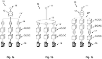
- Fig. 1a shows a charging system 10 with a 50 Hz MV/LV-transformer 12 for an insulation to an MV grid or AC medium-voltage power signal 11.
- the 50 Hz low-voltage signal is transformed by a 50 Hz LV/LV-transformer 14.
- the LV/LV-transformers 14 separate galvanically the plurality of charging poles 19 from each other. The two conversion stages of low-frequency transformers may result in a large system w.r.t. footprint and size. Between each one of the LV/LV-transformers 14 and the respective charging poles 19, an AC/DC-transformer and a DC/DC-transformer is arranged.
- Fig. 1b shows a charging system 10 with a multi-winding 50 Hz transformer 13. This is a system with one conversion stage, thus both transforming MV to LV and providing of the plurality of charging poles 19 from each other.
- Fig. 1c shows a charging system 10 with a first conversion stage of a 50 Hz MV/LV-transformer 12. As a second conversion stage, the system 10 has a low voltage Medium-Frequency Transformer, LV/LV-MFT 17, whose higher frequency is provided by a DC/AC-transformer.
- LV/LV-MFT 17 Low voltage Medium-Frequency Transformer
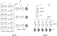
- Fig. 2a shows a charging system 10 with MV-MFTs 14 for a galvanic separation to the MV grid 11. Furthermore, it has LV/LV-MFTs 17 for a galvanic separation of the charging poles 19 from each other.
- Fig. 2b shows a charging system 10 with a first conversion stage, an MV/LV-MFT 15, which is supplied by an MV-DC/AC converter for a high frequency, HF-AC.
- the second conversion stage are LV/LV-MFTs 17 for a galvanic separation of the charging poles 19 from each other.
- Fig. 3a shows a schematic overview over a charging system 10.
- the charging system 10 is connected to an MV grid or AC medium-voltage power signal 11.
- the MV grid 11 is connected to inductor 20.
- the inductor 20 contributes to reduce the current harmonics.
- the inductor 20 is connected to an input 31 of a LIT-based rectifier 30.
- the LIT-based rectifier 30 outputs a MV DC-signal 39, which is fed to a modular DC/DC converter with large step-down gain 40, which delivers an MV HF-AC-signal 49, whose frequency is multiple times the mains frequency, e.g. in a frequency-range of about 5 kHz - 20 kHz.
- the MV HF-AC-signal 49 is fed to a Medium-Frequency Transformer, MFT 50, which transforms it into a low-voltage HF-AC-signal 59.
- the low-voltage power signal 59 may, additionally or as an alternative, be connected to an AC/DC rectifier 65 that outputs the LV DC signal to the DC voltage bus.
- the low-voltage HF-AC-signal 59 is then fed into a plurality of charging boxes 60.
- the charging boxes 60 may be connected to the DC voltage bus.
- Each charging box 60 comprises a charging pole 19.
- the low-voltage HF-AC-signal 59 may be fed into supply modules for computing machines, e.g. servers, for electric motors, and/or further types of power supply boxes.
- Fig. 3b shows a flow diagram 70 of a method according to an embodiment.
- an AC medium-voltage power signal 11 (see Fig. 3a ) of low frequency - e.g. 50 Hz or 60 Hz - is provided.
- the medium-voltage power signal 11 may be part of a MV grid.
- each phase 11a, 11b, 11c of the AC medium-voltage power signal 11 is filtered from each input 31a, 31b, 31c of the LIT-based rectifier 30 by means of an inductor 20a, 20b, 20c.
- the AC MV power signal 11 is transformed into a medium-voltage DC-signal 39, by means of a LIT-based rectifier 30.
- the medium-voltage DC-signal 39 is transformed into a HF-AC medium-voltage signal 49.
- the HF AC medium-voltage signal 39 is transformed into low-voltage power signal 59, by means of a medium-frequency transformer, MFT 50.
- the low-voltage power signal 59 is a HF-AC signal and is configured to serve as a low voltage power signal 61 for at least one charging box 60.
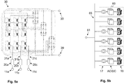
- Fig. 4a schematically shows a subsystem of a charging system 10 as drawn in Fig. 3a .
- the subsystem comprises an AC medium-voltage power signal 11 with phases 11a, 11b, 11c.
- Each phase 11a, 11b, 11c is connected via an inductor 20a, 20b, 20c, respectively, to phase inputs 31a, 31b, 31c of a LIT-based rectifier 30.
- the LIT-based rectifier's first component is a 12-pulse LIT (Line Interphase Transformer) 32, whose outputs 35 are fed to a multi-pulse diode rectifier 37.
- the LIT shown in Fig. 4a (and, analogously, in Fig.
- FIG. 5a depicts the magnetic cores, which couple the inductive components of the LIT, as lines coupled by a magnetic reluctance (a small rectangular box as equivalent circuit diagram).
- the multi-pulse diode rectifier 37 outputs a medium-voltage DC-signal 39.
- the MV DC-signal 39 may be fed into a modular DC/DC converter with large step-down gain 40. Examples of a modular DC/DC converter with large step-down gain 40 are shown in Fig. 4b and 4c.
- Fig. 4b and 4c show the output stages and the flying capacitors of the modular DC/DC converter with large step-down gain 40, possibly implemented as a multilevel flying capacitor inverter.
- Fig. 5a is similar to Fig. 4a , depicting a LIT with an 18-pulse line-side interphase 32 and a respective multi-pulse diode rectifier 37.
- each of the diodes of the multi-pulse diode rectifiers 37 of Fig. 4a or Fig. 5a may be substituted by a thyristor, thus being able to break or to interrupt the power.
- Fig. 5b shows, as an example, a subsystem of an EV charging system, which comprises six charging boxes 60.
- the charging boxes 60 may be connected to a DC voltage bus 65 for low-voltage power distribution.
- Each charging box 60 comprises a low-voltage AC/DC-converter and a charging pole 19, and each charging box 60, except one (the second from the top-most one), comprises a low-voltage MFT 17.
- the charging poles 19 are configured to charge electric vehicles, particularly for fast charging.
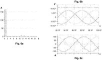
- Fig. 6a shows results of a simulation of an MV grid 11, connected to a charging system 10 with a 12-pulse LIT 30 (see Fig. 4a ).
- the charging system has an output-voltage of 11.7 kV as medium-voltage DC-signal 39, with a power of 2 MW.
- the current-harmonics of the MV grid 11 are depicted.
- the first harmonic has a current of 163 A
- the 11 th harmonic has a current of 5.7 A
- the 11 th harmonic has a current of 3.4 A
- other current-harmonics are not visible.
- FIG. 6b shows a voltage of each phase and its sum of a complete sine-curve.
- Fig. 6c shows the currents of each phase of a complete sine-curve.
- the simulations show the excellent distortion factor of this embodiment, which further provides a cost-efficient solution. Increasing the inductors 20a, 20b, 20c would further improve this result.
Abstract
Description
- The invention relates to the field of power supplies, particularly for a charging system, e.g. for electric vehicles. The invention further relates to a method and to a use of a power supply.
- Charging systems for electric vehicles (EV) require high power levels. For instance, for a range of about 300 to 400 km for the charged vehicle, a charging pole may require about 350 kW. In many cases, EV charging stations have more than one charging pole. This may result in bulky frontends for the system that feeds the charging pole.
- It is therefore an objective of the invention to provide an improved charging system for electric vehicles. This objective is achieved by the subject-matter of the independent claims. Further embodiments are evident from the dependent patent claims and the following description.
- One aspect relates to a charging system that is configured for delivering a low-voltage (LV) power signal to at least one charging box for charging electric vehicles and/or to other types of power supplies. The charging system comprises a LIT-based rectifier (LIT: Line Interphase Transformer), configured for connecting an input of the LIT-based rectifier to an AC medium-voltage power signal and for outputting a medium-voltage DC-signal; a modular DC/DC converter with large step-down gain, configured for transforming the medium-voltage DC-signal into a medium-voltage HF-AC-signal; and a medium-frequency transformer, MFT, configured for transforming the medium-voltage HF-AC-signal into a low-voltage HF-AC-signal for the at least one charging box (HF: high frequency).
- The low-voltage power signal of the EV charging stations may have a voltage, ranging from about 400 V to 1000 V, or about 230 V, or about 110 V. This voltage or the low-voltage range may be the output-voltage of the charging box. The output-voltage of the charging box may be variable, e.g. depending on the charging needs. The input-voltage of the charging box may be a fixed voltage, e.g. ranging from about 400 V to 1000 V. Said input-voltage (and/or the power supply system) may be used for different and/or further types of power supplies with similar power demand, for instance for power data-centres with a plurality of computing servers, and/or for so-called "drives", i.e. electrical machines connected via converter, e.g. in manufacturing centres. The drives may be implemented as electric motors, for instance as low-voltage motors or, after a transformation, as medium-voltage motors, and/or as other machines.
- The power per EV charging station to be delivered may be about 350 kW, particularly for fast charging. EV charging stations may have several charging poles. Not every charging pole in one site may need to deliver this ("full") power, not all cars may be charged at the same time. As an example, an EV charging station may have a power rating of around 2 MW. The AC medium-voltage power signal, which serves as an input for the LIT-based rectifier, may have a so-called medium-voltage (MV) of about 10 kV - 30 kV. The power signal may be part of a medium-voltage grid. The AC medium-voltage power signal may have, e.g., 3 phases, with AC of low frequency, for example of 50 or 60 Hz. The LIT-based rectifier may comprise a line-side interphase transformer - e.g. designed as a 12-pulse LIT or 18-pulse-LIT - and a multi-pulse diode rectifier. The rectifier is configured to output a medium-voltage DC-signal. There may be no galvanic insulation from the medium-voltage power signal. The DC-signal may provide an uncontrolled MV DC-link. Some schematic examples of LITs are depicted in the figures.
- The modular DC/DC converter with large step-down gain may be configured to deliver the MV HF-AC-signal with a frequency of multiple times the mains frequency, for example of about 5 kHz - 20 kHz. One implementation of a modular DC/DC converter with large step-down gain may be a multilevel flying capacitor inverter. The MV HF-AC-signal is fed into the Medium-Frequency Transformer, MFT, configured for transforming the medium-voltage HF-AC-signal into the low-voltage HF-AC-signal, which may be an input for the at least one charging box and/or for the charging pole. The MFT may provide both a galvanic insulation from the medium-voltage power signal and a voltage adaption to the low-voltage HF-AC-signal. In at least some countries, the galvanic insulation from the MV grid may be a legal requirement. In case of more than one charging box, the charging boxes may comprise means for a galvanic insulation between the charging poles.
- Accordingly, the charging system a simple system at low manufacturing-cost. Nevertheless, it can provide high power, due to its connection to an AC medium-voltage power signal or a medium-voltage grid. Moreover, the charging system is of small-size and low losses, for instance by avoiding large and expensive 50 Hz transformers.
- In various embodiments, the charging system further comprises an inductor, configured for a filtering connection between each phase of the AC medium-voltage power signal and each input of the LIT-based rectifier. Thus, the inductor, which connects MV grid and LIT-based rectifier, is designed to reduce the current harmonics. In at least some countries, this may be a legal and/or a standard requirement, e.g. to comply with relevant MV grid standards, e.g. with IEEE 519 or IEC 61000-3-6. Advantageously, said requirements may be fulfilled without complex and expensive active frontends to the MV grid, thus leading to a simpler design, lower manufacturing-cost, and/or reducing maintenance efforts.
- In various embodiments, the LIT-based rectifier comprises a multi-pulse LIT with a pulse number of 12, of 18, of 24, or of higher than 24. This advantageously leads to a reduction of the harmonics, thus reducing the need for an inductor as described above and/or below and/or reducing its impedance. This further contributes to an efficient power supply system, with quite low complexity in design and manufacturing.
- In various embodiments, the LIT-based rectifier comprises a line-side interphase transformer, LIT, and a multi-pulse diode rectifier. This combination of components leads to a modular subsystem of a clear design and/or improved maintenance. The multi-pulse diode rectifier may be realized as a parallel-connected diode rectifier (see, e.g., the figures below). Alternatively, the multi-pulse diode rectifier may be realized as a series-connected diode rectifier, where the "DC-ends" of the diode rectifier bridges are connected in series.
- In some embodiments, each one of the diodes of the multi-pulse diode rectifier is realized as a thyristor. This advantageously provides a fast and simple breaking capability, e.g. in case of an overcurrent.
- In various embodiments, the charging system further comprises a plurality of charging boxes, wherein each one of the plurality of charging boxes comprises a low-voltage MFT, a low-voltage AC/DC-converter, and a charging pole for charging electric vehicles. The plurality of charging boxes may comprise, e.g., two, four, six, a dozen and/or more charging boxes. This design of ensures each one of the plurality of charging boxes ensures a galvanic separation or insulation between the charging poles, which may be a legal and/or standard requirement in at least some countries.
- Additionally or as an alternative, the charging system or power supply system may be connected to other types of power supplies and/or bridges or control modules. Said power supplies, bridges, and/or control modules may be used for supplying a plurality of servers or other computer in a data-centre, a site for server-clouds, other computing applications, and/or for a plurality of electric motors.
- An aspect relates to a method for transforming an AC medium-voltage power signal into a low-voltage power signal for at least one charging box for charging electric vehicles. The method comprising the steps of:
- providing the AC medium-voltage power signal;
- transforming, by means of a LIT-based rectifier, the AC medium-voltage power signal into a medium-voltage DC-signal;
- transforming the medium-voltage DC-signal into a HF-AC medium-voltage signal; and transforming, by means of a medium-frequency transformer, MFT, the HF AC medium-voltage signal into the low-voltage power signal, wherein the low-voltage power signal is a HF-AC signal and is configured to serve as a low-voltage power signal for at least one charging box.
- This method advantageously provides an easy-to-handle process to deliver high power to a plurality of charging boxes and/or charging poles for charging electric vehicles. Moreover, this concept contributes to a highly scalable design of charging poles, particularly for fast charging.
- In various embodiments, the method further comprises the step of filtering, by means of an inductor, each phase of the AC medium-voltage power signal from each input of the LIT-based rectifier. This leads to an easy concept, while complying with high electrical standards, including towards MV grids.
- An aspect relates to a charging system described above and/or below for delivering energy to a charging box and/or to a charging pole for charging electric vehicles.
- In various embodiments, the low-voltage HF-AC-signal (59) is connected to a DC voltage bus for low-voltage power distribution. In some embodiments, the low-voltage HF-AC-signal is connected to a AC/DC transformer that outputs the LV DC signal to the DC voltage bus. The AC/DC transformer may be a rectifier, an AC/DC, and/or a similar component. The DC voltage bus advantageously provides a kind of multipurpose interface, which may serve as a basis for a plurality of use-cases and/or devices to connect to the DC voltage bus.
- An aspect relates to a use of a charging system described above and/or below for delivering energy to a charging box, to a charging pole for charging electric vehicles, to a data-centre, and/or to low-voltage drives. The charging system or power supply system may be used in a data-centre to power, e.g., a plurality of servers, for instance a server cluster or a server cloud. The charging system or power supply system may be used in a manufacturing site to power a plurality of electric motors. The electric motors may have or comprise a bridge or control module with a function similar to the function of a charging box for EVs, in order to power electric motors of different voltages, frequencies, and/or power requirements.
- For further clarification, the invention is described by means of embodiments shown in the figures. These embodiments are to be considered as examples only, but not as limiting.
- The figures depict:
- Fig. 1a, 1b, 1c
- schematically various designs of a charging system according to embodiments;
- Fig. 2a, 2b
- schematically various designs of a charging system according further embodiments;
- Fig. 3a, 3b
- schematically a charging system and a method according to an embodiment;
- Fig. 4a, 4b, 4c
- schematically subsystems of a charging system according to embodiments;
- Fig. 5a, 5b
- schematically further subsystems of a charging system according to embodiments;
- Fig. 6a, 6b, 6c
- schematically simulations of an MV grid behaviour of a charging system according to an embodiment;
-
Fig. 1a shows a chargingsystem 10 with a 50 Hz MV/LV-transformer 12 for an insulation to an MV grid or AC medium-voltage power signal 11. The 50 Hz low-voltage signal is transformed by a 50 Hz LV/LV-transformer 14. The LV/LV-transformers 14 separate galvanically the plurality of chargingpoles 19 from each other. The two conversion stages of low-frequency transformers may result in a large system w.r.t. footprint and size. Between each one of the LV/LV-transformers 14 and therespective charging poles 19, an AC/DC-transformer and a DC/DC-transformer is arranged. -
Fig. 1b shows a chargingsystem 10 with a multi-winding 50Hz transformer 13. This is a system with one conversion stage, thus both transforming MV to LV and providing of the plurality of chargingpoles 19 from each other.Fig. 1c shows a chargingsystem 10 with a first conversion stage of a 50 Hz MV/LV-transformer 12. As a second conversion stage, thesystem 10 has a low voltage Medium-Frequency Transformer, LV/LV-MFT 17, whose higher frequency is provided by a DC/AC-transformer. -
Fig. 2a shows a chargingsystem 10 with MV-MFTs 14 for a galvanic separation to theMV grid 11. Furthermore, it has LV/LV-MFTs 17 for a galvanic separation of the chargingpoles 19 from each other. -
Fig. 2b shows a chargingsystem 10 with a first conversion stage, an MV/LV-MFT 15, which is supplied by an MV-DC/AC converter for a high frequency, HF-AC. The second conversion stage are LV/LV-MFTs 17 for a galvanic separation of the chargingpoles 19 from each other. -
Fig. 3a shows a schematic overview over a chargingsystem 10. The chargingsystem 10 is connected to an MV grid or AC medium-voltage power signal 11. TheMV grid 11 is connected toinductor 20. Theinductor 20 contributes to reduce the current harmonics. Theinductor 20 is connected to aninput 31 of a LIT-basedrectifier 30. The LIT-basedrectifier 30 outputs a MV DC-signal 39, which is fed to a modular DC/DC converter with large step-downgain 40, which delivers an MV HF-AC-signal 49, whose frequency is multiple times the mains frequency, e.g. in a frequency-range of about 5 kHz - 20 kHz. The MV HF-AC-signal 49 is fed to a Medium-Frequency Transformer,MFT 50, which transforms it into a low-voltage HF-AC-signal 59. The low-voltage power signal 59 may, additionally or as an alternative, be connected to an AC/DC rectifier 65 that outputs the LV DC signal to the DC voltage bus. The low-voltage HF-AC-signal 59 is then fed into a plurality of chargingboxes 60. In an embodiment, the chargingboxes 60 may be connected to the DC voltage bus. Each chargingbox 60 comprises acharging pole 19. Additionally or as an alternative, the low-voltage HF-AC-signal 59 may be fed into supply modules for computing machines, e.g. servers, for electric motors, and/or further types of power supply boxes. -
Fig. 3b shows a flow diagram 70 of a method according to an embodiment. In astep 71, an AC medium-voltage power signal 11 (seeFig. 3a ) of low frequency - e.g. 50 Hz or 60 Hz - is provided. The medium-voltage power signal 11 may be part of a MV grid. In astep 72, eachphase voltage power signal 11 is filtered from eachinput rectifier 30 by means of aninductor step 73, the ACMV power signal 11 is transformed into a medium-voltage DC-signal 39, by means of a LIT-basedrectifier 30. In astep 74, the medium-voltage DC-signal 39 is transformed into a HF-AC medium-voltage signal 49. In astep 75, the HF AC medium-voltage signal 39 is transformed into low-voltage power signal 59, by means of a medium-frequency transformer,MFT 50. The low-voltage power signal 59 is a HF-AC signal and is configured to serve as a lowvoltage power signal 61 for at least onecharging box 60. -
Fig. 4a schematically shows a subsystem of a chargingsystem 10 as drawn inFig. 3a . The subsystem comprises an AC medium-voltage power signal 11 withphases phase inductor inputs rectifier 30. The LIT-based rectifier's first component is a 12-pulse LIT (Line Interphase Transformer) 32, whoseoutputs 35 are fed to amulti-pulse diode rectifier 37. The LIT shown inFig. 4a (and, analogously, inFig. 5a ) depicts the magnetic cores, which couple the inductive components of the LIT, as lines coupled by a magnetic reluctance (a small rectangular box as equivalent circuit diagram). Themulti-pulse diode rectifier 37 outputs a medium-voltage DC-signal 39. The MV DC-signal 39 may be fed into a modular DC/DC converter with large step-downgain 40. Examples of a modular DC/DC converter with large step-downgain 40 are shown inFig. 4b and 4c. Fig. 4b and 4c show the output stages and the flying capacitors of the modular DC/DC converter with large step-downgain 40, possibly implemented as a multilevel flying capacitor inverter. Each one of itsoutputs 49 are fed to a medium-frequency transformer, MFT (50), thus delivering a low-voltage HF-AC-signal 59.Fig. 5a is similar toFig. 4a , depicting a LIT with an 18-pulse line-side interphase 32 and a respectivemulti-pulse diode rectifier 37. As an alternative, each of the diodes of themulti-pulse diode rectifiers 37 ofFig. 4a orFig. 5a may be substituted by a thyristor, thus being able to break or to interrupt the power. -
Fig. 5b shows, as an example, a subsystem of an EV charging system, which comprises six chargingboxes 60. The chargingboxes 60 may be connected to aDC voltage bus 65 for low-voltage power distribution. Each chargingbox 60 comprises a low-voltage AC/DC-converter and acharging pole 19, and each chargingbox 60, except one (the second from the top-most one), comprises a low-voltage MFT 17. The chargingpoles 19 are configured to charge electric vehicles, particularly for fast charging. -
Fig. 6a shows results of a simulation of anMV grid 11, connected to acharging system 10 with a 12-pulse LIT 30 (seeFig. 4a ). The charging system has aninductor signal 39, with a power of 2 MW. InFig. 6a , the current-harmonics of theMV grid 11 are depicted. The first harmonic has a current of 163 A, the 11th harmonic has a current of 5.7 A, the 11th harmonic has a current of 3.4 A, and other current-harmonics are not visible.Fig. 6b shows a voltage of each phase and its sum of a complete sine-curve.Fig. 6c shows the currents of each phase of a complete sine-curve. The simulations show the excellent distortion factor of this embodiment, which further provides a cost-efficient solution. Increasing theinductors -
- 10
- charging system
- 11
- medium-voltage signal
- 11a, 11b, 11c
- phases of a medium-voltage signal
- 17
- low-voltage MFT
- 19
- charging pole
- 20
- inductor
- 20a, 20b, 20c
- inductors of the phases
- 30
- Line Interphase Transformer, LIT
- 31
- input of a LIT
- 31a, 31b, 31c
- inputs of each phase of the LIT
- 32
- line-side interphase transformer
- 37
- multi-pulse diode rectifier
- 39
- medium-voltage DC-signal
- 40
- modular DC/DC converter with large step-down gain
- 49
- medium-voltage HF-AC-signal
- 50
- Medium-Frequency Transformer, MFT
- 59
- low-voltage HF-AC-signal
- 60
- charging box
- 61
- power signal
- 65
- DC voltage bus for LV power distribution
- 70
- flow diagram
- 71 - 75
- steps
Claims (12)
- A charging system (10) configured for delivering a low-voltage power signal (61) to at least one charging box (60) for charging electric vehicles, the charging system (10) comprising:a line interphase transformer, LIT, based rectifier (30), configured for connecting an input (31) of the LIT-based rectifier (30) to an AC medium-voltage power signal (11) and for outputting a medium-voltage DC-signal (39);a modular DC/DC converter with large step-down gain (40), configured for transforming the medium-voltage DC-signal (39) into a medium-voltage HF-AC-signal (49); anda medium-frequency transformer, MFT (50), configured for transforming the medium-voltage HF-AC-signal (49) into a low-voltage HF-AC-signal (59) for the at least one charging box (60).
- The charging system (10) according to claim 1, further comprising:
an inductor (20a, 20b, 20c), configured for a filtering connection between each phase of the AC medium-voltage power signal (11a, 11b, 11c) and each input (31a, 31b, 31c) of the LIT-based rectifier (30). - The charging system (10) according to any one of the preceding claims,
wherein the LIT-based rectifier (30) comprises a multi-pulse LIT with a pulse number of 12, of 18, of 24, or of higher than 24. - The charging system (10) according to any one of the preceding claims,
wherein the LIT-based rectifier (30) comprises a LIT (32) and a multi-pulse diode rectifier (37). - The charging system (10) according to claim 4,
wherein each one of the diodes of the multi-pulse diode rectifier (37) is realized as a thyristor. - The charging system (10) according to any one of the preceding claims, further comprising a plurality of charging boxes (60), wherein each one of the plurality of charging boxes (60) comprises:a low-voltage MFT (17),a low-voltage AC/DC-converter, anda charging pole (19) for charging electric vehicles.
- A method for transforming an AC medium-voltage power signal (11) into a low-voltage power signal (61) for at least one charging box (60) for charging electric vehicles, the method comprising the steps of:providing the AC medium-voltage power signal (11);transforming, by means of a LIT-based rectifier (30), the AC medium-voltage power signal (11) into a medium-voltage DC-signal (39);transforming the medium-voltage DC-signal (39) into a HF-AC medium-voltage signal (49); andtransforming, by means of a medium-frequency transformer, MFT (50), the HF-AC medium-voltage signal (39) into the low-voltage power signal (59),wherein the low-voltage power signal (59) is a HF-AC signal and is configured to serve as a low-voltage power signal (61) for at least one charging box (60).
- The method according to claim 7, further comprising the step of:
filtering, by means of an inductor (20a, 20b, 20c), each phase of the AC medium-voltage power signal (11a, 11b, 11c) from each input (31a, 31b, 31c) of the LIT-based rectifier (30). - A charging system or power supply system (10) according to any one of the claims 1 to 6 for delivering energy to a charging box (60), to a charging pole (19) for charging electric vehicles, to a data-centre, to an energy storage, and/or to drives.
- The charging system or power supply system (10) of claim 9, wherein the low-voltage HF-AC-signal (59) is connected to a DC voltage bus (65) for low-voltage power distribution.
- The charging system or power supply system (10) of claim 9, wherein the low-voltage HF-AC-signal (59) is connected to an AC/DC transformer that outputs the LV DC signal to the DC voltage bus (65).
- Use of a charging system or power supply system (10) according to claim 9 or 10 for delivering energy to a charging box (60), to a charging pole (19) for charging electric vehicles, to a data-centre, and/or to low-voltage drives.
Priority Applications (4)
| Application Number | Priority Date | Filing Date | Title |
|---|---|---|---|
| EP20172514.0A EP3905480A1 (en) | 2020-04-30 | 2020-04-30 | A charging system for electric vehicles |
| PCT/EP2021/060252 WO2021219443A1 (en) | 2020-04-30 | 2021-04-20 | A charging system for electric vehicles |
| CN202180031937.3A CN115956033A (en) | 2020-04-30 | 2021-04-20 | Charging system for electric vehicle |
| US17/977,428 US20230050293A1 (en) | 2020-04-30 | 2022-10-31 | Charging System for Electric Vehicles |
Applications Claiming Priority (1)
| Application Number | Priority Date | Filing Date | Title |
|---|---|---|---|
| EP20172514.0A EP3905480A1 (en) | 2020-04-30 | 2020-04-30 | A charging system for electric vehicles |
Publications (1)
| Publication Number | Publication Date |
|---|---|
| EP3905480A1 true EP3905480A1 (en) | 2021-11-03 |
Family
ID=70680189
Family Applications (1)
| Application Number | Title | Priority Date | Filing Date |
|---|---|---|---|
| EP20172514.0A Pending EP3905480A1 (en) | 2020-04-30 | 2020-04-30 | A charging system for electric vehicles |
Country Status (4)
| Country | Link |
|---|---|
| US (1) | US20230050293A1 (en) |
| EP (1) | EP3905480A1 (en) |
| CN (1) | CN115956033A (en) |
| WO (1) | WO2021219443A1 (en) |
Citations (2)
| Publication number | Priority date | Publication date | Assignee | Title |
|---|---|---|---|---|
| EP2875986A1 (en) * | 2013-11-22 | 2015-05-27 | Hochschule für angewandte Wissenschaften Deggendorf | Charging station for electric vehicles with integrated control system for regulation of the charging output power of a plurality of charging points |
| DE102016123066A1 (en) * | 2016-11-30 | 2018-05-30 | Dr. Ing. H.C. F. Porsche Aktiengesellschaft | loader |
-
2020
- 2020-04-30 EP EP20172514.0A patent/EP3905480A1/en active Pending
-
2021
- 2021-04-20 CN CN202180031937.3A patent/CN115956033A/en active Pending
- 2021-04-20 WO PCT/EP2021/060252 patent/WO2021219443A1/en active Application Filing
-
2022
- 2022-10-31 US US17/977,428 patent/US20230050293A1/en active Pending
Patent Citations (2)
| Publication number | Priority date | Publication date | Assignee | Title |
|---|---|---|---|---|
| EP2875986A1 (en) * | 2013-11-22 | 2015-05-27 | Hochschule für angewandte Wissenschaften Deggendorf | Charging station for electric vehicles with integrated control system for regulation of the charging output power of a plurality of charging points |
| DE102016123066A1 (en) * | 2016-11-30 | 2018-05-30 | Dr. Ing. H.C. F. Porsche Aktiengesellschaft | loader |
Non-Patent Citations (1)
| Title |
|---|
| NIERMANN C ED - LEONHARD W ET AL: "NEW RECTIFIER CIRCUITS WITH LOW MAINS POLLUTION AND ADDITIONAL LOW COST INVERTER FOR ENERGY RECOVERY", PROCEEDINGS OF THE EUROPEAN CONFERENCE ON POWER ELECTRONICS AND APPLICATIONS. (EPE). AACHEN, 9 - 12 OCTOBER, 1989, DUSSELDORF, EPE SECRETARIAT, DE, vol. 3, 9 October 1989 (1989-10-09), pages 1131 - 1136, XP000143527 * |
Also Published As
| Publication number | Publication date |
|---|---|
| CN115956033A (en) | 2023-04-11 |
| WO2021219443A1 (en) | 2021-11-04 |
| US20230050293A1 (en) | 2023-02-16 |
Similar Documents
| Publication | Publication Date | Title |
|---|---|---|
| US10391870B2 (en) | Modular power electronics system for charging an electrically operated vehicle | |
| US10873265B2 (en) | Bidirectional three-phase direct current (DC)/DC converters | |
| US11050352B2 (en) | AC-to-DC converter system | |
| CN110771000B (en) | Constant current fast charge of electric vehicles via DC grid drive with dual inverter | |
| US8466661B2 (en) | Low-voltage harmonic filter for full-scale converter systems | |
| CN108092371B (en) | Charging and discharging device | |
| CN107921880B (en) | Vehicle-side power circuit for supplying power in an electric vehicle | |
| WO2018227307A1 (en) | Constant current fast charging of electric vehicles via dc grid using dual inverter drive | |
| EP2495862A2 (en) | Multilevel power converter or inverter arrangement using H bridges | |
| RU2375804C2 (en) | Ship electric power system | |
| EP2913905A1 (en) | DC power transmission systems and method of assembling the same | |
| CN114362335A (en) | Power conversion framework applied to solid-state transformer and corresponding charging system | |
| CN113726136B (en) | conversion device | |
| US9479077B1 (en) | Three-phase power supply system | |
| EP3905480A1 (en) | A charging system for electric vehicles | |
| CN111890998A (en) | In-phase power supply device, through type in-phase power supply structure, system and control method | |
| CN113228461A (en) | Charging station adopting high-frequency power distribution network | |
| US9490720B1 (en) | Power conversion with solid-state transformer | |
| Ratti et al. | Application studies of the modular multilevel converter topology to the acceleration grid power supply of the DEMO neutral beam injector | |
| Atanalian et al. | Modular multilevel converters for fast charging stations of electric vehicles: An overview | |
| EP3904151A1 (en) | Power supply system for bidirectional energy flow | |
| CN113726137B (en) | conversion device | |
| US20180358808A1 (en) | Device And Method For Controlling A Load Flow In An Alternating-Voltage Network | |
| Goodman et al. | DC side ripple cancellation in a cascaded multi-level topology for automotive applications | |
| CN112994007A (en) | Remote power distribution unit architecture based on PWM rectification |
Legal Events
| Date | Code | Title | Description |
|---|---|---|---|
| PUAI | Public reference made under article 153(3) epc to a published international application that has entered the european phase |
Free format text: ORIGINAL CODE: 0009012 |
|
| STAA | Information on the status of an ep patent application or granted ep patent |
Free format text: STATUS: THE APPLICATION HAS BEEN PUBLISHED |
|
| AK | Designated contracting states |
Kind code of ref document: A1 Designated state(s): AL AT BE BG CH CY CZ DE DK EE ES FI FR GB GR HR HU IE IS IT LI LT LU LV MC MK MT NL NO PL PT RO RS SE SI SK SM TR |
|
| B565 | Issuance of search results under rule 164(2) epc |
Effective date: 20200917 |
|
| STAA | Information on the status of an ep patent application or granted ep patent |
Free format text: STATUS: REQUEST FOR EXAMINATION WAS MADE |
|
| 17P | Request for examination filed |
Effective date: 20220503 |
|
| RBV | Designated contracting states (corrected) |
Designated state(s): AL AT BE BG CH CY CZ DE DK EE ES FI FR GB GR HR HU IE IS IT LI LT LU LV MC MK MT NL NO PL PT RO RS SE SI SK SM TR |
|
| RAP1 | Party data changed (applicant data changed or rights of an application transferred) |
Owner name: ABB-E-MOBILITY B.V. |