EP3836483A1 - Thermal modeling for cables transmitting data and power - Google Patents
Thermal modeling for cables transmitting data and power Download PDFInfo
- Publication number
- EP3836483A1 EP3836483A1 EP21156406.7A EP21156406A EP3836483A1 EP 3836483 A1 EP3836483 A1 EP 3836483A1 EP 21156406 A EP21156406 A EP 21156406A EP 3836483 A1 EP3836483 A1 EP 3836483A1
- Authority
- EP
- European Patent Office
- Prior art keywords
- cables
- pse
- cable
- data
- thermal
- Prior art date
- Legal status (The legal status is an assumption and is not a legal conclusion. Google has not performed a legal analysis and makes no representation as to the accuracy of the status listed.)
- Granted
Links
- 238000000034 method Methods 0.000 claims abstract description 40
- 238000012358 sourcing Methods 0.000 claims abstract description 12
- 238000012502 risk assessment Methods 0.000 claims description 13
- 238000005259 measurement Methods 0.000 claims description 11
- 238000004590 computer program Methods 0.000 claims description 4
- 238000004891 communication Methods 0.000 description 20
- 230000036541 health Effects 0.000 description 17
- 239000004020 conductor Substances 0.000 description 14
- 238000004364 calculation method Methods 0.000 description 13
- 238000010438 heat treatment Methods 0.000 description 10
- 230000008569 process Effects 0.000 description 8
- 238000000899 pressurised-fluid extraction Methods 0.000 description 4
- 238000012384 transportation and delivery Methods 0.000 description 4
- 238000004422 calculation algorithm Methods 0.000 description 3
- 230000008859 change Effects 0.000 description 3
- 239000000835 fiber Substances 0.000 description 3
- 238000009434 installation Methods 0.000 description 3
- RYGMFSIKBFXOCR-UHFFFAOYSA-N Copper Chemical compound [Cu] RYGMFSIKBFXOCR-UHFFFAOYSA-N 0.000 description 2
- 238000004458 analytical method Methods 0.000 description 2
- 239000010949 copper Substances 0.000 description 2
- 229910052802 copper Inorganic materials 0.000 description 2
- 238000001514 detection method Methods 0.000 description 2
- 230000006870 function Effects 0.000 description 2
- 238000009413 insulation Methods 0.000 description 2
- 239000000463 material Substances 0.000 description 2
- 230000000737 periodic effect Effects 0.000 description 2
- 230000009471 action Effects 0.000 description 1
- 230000006399 behavior Effects 0.000 description 1
- 230000005540 biological transmission Effects 0.000 description 1
- 230000001419 dependent effect Effects 0.000 description 1
- 230000006866 deterioration Effects 0.000 description 1
- 238000005516 engineering process Methods 0.000 description 1
- 239000011888 foil Substances 0.000 description 1
- 230000003862 health status Effects 0.000 description 1
- 230000020169 heat generation Effects 0.000 description 1
- 238000007689 inspection Methods 0.000 description 1
- 239000004973 liquid crystal related substance Substances 0.000 description 1
- 230000007774 longterm Effects 0.000 description 1
- 238000007726 management method Methods 0.000 description 1
- 238000004519 manufacturing process Methods 0.000 description 1
- 238000012986 modification Methods 0.000 description 1
- 230000004048 modification Effects 0.000 description 1
- 230000003287 optical effect Effects 0.000 description 1
- 230000037361 pathway Effects 0.000 description 1
- 238000013439 planning Methods 0.000 description 1
- 230000008654 plant damage Effects 0.000 description 1
- 230000000750 progressive effect Effects 0.000 description 1
- 238000012552 review Methods 0.000 description 1
- 239000004065 semiconductor Substances 0.000 description 1
- 239000007787 solid Substances 0.000 description 1
- 239000004557 technical material Substances 0.000 description 1
- 238000012360 testing method Methods 0.000 description 1
- 230000008646 thermal stress Effects 0.000 description 1
- 238000012546 transfer Methods 0.000 description 1
- 238000011179 visual inspection Methods 0.000 description 1
Images


Classifications
-
- G—PHYSICS
- G01—MEASURING; TESTING
- G01K—MEASURING TEMPERATURE; MEASURING QUANTITY OF HEAT; THERMALLY-SENSITIVE ELEMENTS NOT OTHERWISE PROVIDED FOR
- G01K3/00—Thermometers giving results other than momentary value of temperature
- G01K3/005—Circuits arrangements for indicating a predetermined temperature
-
- H—ELECTRICITY
- H04—ELECTRIC COMMUNICATION TECHNIQUE
- H04L—TRANSMISSION OF DIGITAL INFORMATION, e.g. TELEGRAPHIC COMMUNICATION
- H04L12/00—Data switching networks
- H04L12/02—Details
- H04L12/10—Current supply arrangements
-
- G—PHYSICS
- G01—MEASURING; TESTING
- G01K—MEASURING TEMPERATURE; MEASURING QUANTITY OF HEAT; THERMALLY-SENSITIVE ELEMENTS NOT OTHERWISE PROVIDED FOR
- G01K13/00—Thermometers specially adapted for specific purposes
-
- G—PHYSICS
- G06—COMPUTING; CALCULATING OR COUNTING
- G06F—ELECTRIC DIGITAL DATA PROCESSING
- G06F30/00—Computer-aided design [CAD]
- G06F30/20—Design optimisation, verification or simulation
-
- H—ELECTRICITY
- H04—ELECTRIC COMMUNICATION TECHNIQUE
- H04L—TRANSMISSION OF DIGITAL INFORMATION, e.g. TELEGRAPHIC COMMUNICATION
- H04L12/00—Data switching networks
- H04L12/28—Data switching networks characterised by path configuration, e.g. LAN [Local Area Networks] or WAN [Wide Area Networks]
- H04L12/40—Bus networks
- H04L12/40006—Architecture of a communication node
- H04L12/40045—Details regarding the feeding of energy to the node from the bus
Landscapes
- Engineering & Computer Science (AREA)
- Physics & Mathematics (AREA)
- Computer Networks & Wireless Communication (AREA)
- Signal Processing (AREA)
- General Physics & Mathematics (AREA)
- Theoretical Computer Science (AREA)
- Computer Hardware Design (AREA)
- Evolutionary Computation (AREA)
- Geometry (AREA)
- General Engineering & Computer Science (AREA)
- Remote Monitoring And Control Of Power-Distribution Networks (AREA)
- Laying Of Electric Cables Or Lines Outside (AREA)
Abstract
Description
- The present disclosure relates generally to communications networks, and more particularly, to thermal modeling for cables transmitting power and data communications.
- Communications cables that are used to deliver power and data simultaneously may encounter self-heating due to a combination of currents carried in the cables, how the cables are installed (e.g., cable bundling), and what type of cables are used. Heat generation in cable bundles is an issue that can greatly affect performance and cause damage to a cable plant.
-
-
Figure 1 illustrates an example of a network in which embodiments described herein may be implemented. -
Figure 2 depicts an example of a network device useful in implementing embodiments described herein. -
Figure 3 is a flowchart illustrating an overview of a process for thermal modeling of cables, in accordance with one embodiment. -
Figure 4 illustrates detection of cable adjacencies, in accordance with one embodiment. -
Figure 5 illustrates detection of cable adjacencies, in accordance with another embodiment. -
Figure 6 illustrates use of a TDR (Time Domain Reflectometer) to determine cable length and health, in accordance with one embodiment. -
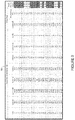
Figure 7 illustrates an example of a risk assessment table providing cable thermal status, in accordance with one embodiment. -
Figure 8 illustrates an example of a risk assessment table providing cable thermal status, in accordance with another embodiment. -
Figure 9 illustrates an example of a risk assessment table providing cable thermal status, in accordance with another embodiment. -
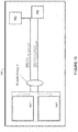
Figure 10 illustrates a graphical view providing risk assessment and cable thermal status, in accordance with one embodiment. - Corresponding reference characters indicate corresponding parts throughout the several views of the drawings.
- Aspects of the invention are set out in the independent claims and preferred features are set out in the dependent claims. Features of one aspect may be applied to each aspect alone or in combination with other aspects.
- In one embodiment, a method generally comprises receiving at a thermal modeling module, data from a Power Sourcing Equipment device (PSE) for cables extending from the PSE to Powered Devices (PDs), the cables configured to transmit power and data from the PSE to the PDs, calculating at the thermal modeling module, thermal characteristics for the cables based on the data, and identifying a thermal rise above a specified threshold at one of the cables. The data comprises real-time electrical data for the cables.
- In another embodiment, an apparatus generally comprises an interface for receiving data from a Power Sourcing Equipment device (PSE) for cables extending from the PSE to Powered Devices (PDs), the cables configured to transmit power and data from the PSE to the PDs, the data comprising real-time electrical data for the cables, a processor for calculating thermal characteristics for the cables based on the data and identifying a thermal rise above a specified threshold at one of the cables, and memory for storing wire gauges and associated cable temperature ratings.
- In yet another embodiment, logic is encoded on one or more non-transitory computer readable media for execution and when executed by a processor operable to process data from a Power Sourcing Equipment device (PSE) for cables extending from the PSE to Powered Devices (PDs), the cables configured to transmit power and data from the PSE to the PDs, the data comprising real-time electrical data for the cables, calculate thermal characteristics for the cables based on the data, and identify a thermal rise above a specified threshold at one of the cables.
- The following description is presented to enable one of ordinary skill in the art to make and use the embodiments. Descriptions of specific embodiments and applications are provided only as examples, and various modifications will be readily apparent to those skilled in the art. The general principles described herein may be applied to other applications without departing from the scope of the embodiments. Thus, the embodiments are not to be limited to those shown, but are to be accorded the widest scope consistent with the principles and features described herein. For purpose of clarity, details relating to technical material that is known in the technical fields related to the embodiments have not been described in detail.
- In systems used to simultaneously transmit power and data communications (e.g., Power over Ethernet (PoE), Power over Fiber (PoF), and the like), cable heating may degrade the reliability of the communications signals that are carried over the cables and damage the cable plant. Cable plant damage is often a direct result of thermal stress occurring in unattended or non-visible locations. In some cases, powered devices may still operate on a thermally stressed cable with uncertain operation, thereby leaving a user confused as to how to debug the system. High temperatures may also lead to higher power costs due to more power dissipated in the cables. In conventional systems, visible inspection may be needed to comply with standards (e.g., NEC (National Electrical Code), IEEE (Institute of Electrical and Electronics Engineers) 802.3) and determine the operational ability of the cable plant between the power source equipment and the powered devices. Many instances of failure may be missed or ignored. As PoE standards allow for higher power transmissions, temperature concerns are expected to become more prevalent.
- The embodiments described herein provide real-time thermal modeling in cables that are used to carry data and power simultaneously. Real-time measurements provide an accurate and up-to-date analysis of a cable plant health assessment. The embodiments may be used, for example, to identify power and thermal impact due to self-heating and provide alerts for possible over heat conditions. One or more embodiments may be used to limit power output based on the modeling or prevent modes that may result in unwanted cable behavior such as heat damage to the cable or other unintended consequences. As described in detail below, one or more embodiments may collect cable heating factors (e.g., current carried in cable, cable type, cable installation, etc.) and use this data to model expected temperature rises and other health assessment characteristics in the cables to determine if the cable can handle the power level and if the integrity of the data carried across the cable is at risk.
- Referring now to the drawings, and first to
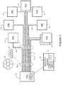
Figure 1 , an example of a network in which embodiments described herein may be implemented is shown. The embodiments operate in the context of a data communications network including multiple network devices. The network may include any number of network devices in communication via any number of nodes (e.g., routers, switches, gateways, controllers, or other network devices), which facilitate passage of data within the network. The network devices may communicate over or be in communication with one or more networks (e.g., local area network (LAN), metropolitan area network (MAN), wide area network (WAN), virtual private network (VPN) (e.g., Ethernet virtual private network (EVPN),layer 2 virtual private network (L2VPN)), virtual local area network (VLAN), enterprise network, corporate network, data center, Internet, intranet, or any other network). - The network may be configured for Power over Ethernet (PoE), Power over Fiber (PoF), or any other power over communications cable system that is used to pass electric power along with data to allow a single cable to provide both data connectivity and electric power to network devices such as wireless access points, IP (Internet Protocol) cameras, VoIP (Voice over IP) phones, video cameras, point-of-sale devices, security access control devices, residential devices, building automation, industrial automation, and many other devices. Signals may be exchanged among communications equipment and power transmitted from power sourcing equipment to powered devices.
- As shown in the simplified example of
Figure 1 , the network may include a Power Sourcing Equipment device (PSE) 10 in communication with any number of Powered Devices (PDs) 12 viacables 14. The PSE may be a network device such as a switch that provides (sources) power on thecable 14. ThePSE 10 may be configured to delivery power at one or more output levels (e.g., programmable PoE). The network may include any number ofPSEs 10 in communication with any number ofPDs 12. The PD 12 is powered by the PSE 10 and consumes energy. - The
cables 14 are configured to transmit both power and data from thePSE 10 to thePDs 12. Thecables 14 may be formed from any material suitable to carry both power and data (e.g., copper, fiber). Thecables 14 may comprise, for example Catx cable (e.g., category 5 twisted pair (e.g., four pair) Ethernet cabling) or any other type of cable. Thecables 14 may extend between thePSE 10 andPDs 12 at a distance, for example, of 10 meters, 100 meters, or any other length. Thecables 14 may be arranged in any configuration. For example, thecables 14 may be bundled together in one ormore groups 13 or stacked in one ormore groups 15 as shown schematically in cross-section inFigure 1 . Any number ofcables 14 may be bundled together. Thecables 14 may have a round, flat, oval, or any other cross-sectional shape and may include any number or type of conductors (e.g., solid or stranded wires). Thecables 14 may be bundled together at onelocation 16 while not bundled together at anotherlocation 17, for example. - The
cable 14 may be rated for one or more power levels, a maximum power level, a maximum temperature, or identified according to one or more categories indicating acceptable power level usage, for example. In one example, thecables 14 correspond to a standardized wire gauge system such as AWG (American Wire Gauge). For different gauge wire, AWG provides data including diameter, area, resistance per length, ampacity (maximum amount of current a conductor can carry before sustaining immediate or progressive deterioration), and fusing current (how much current it takes to melt a wire in free air). Various other standards (e.g., NEC (National Electrical Code), UL (Underwriters Laboratories)) may be used to provide various requirements for the cable and cable system and provide temperature ratings or limits, or other information. This data may be stored in a thermal modeling system for reference in providing a cable thermal status, as described below. - As noted above, the
cables 14 may encounter self-heating. For example, when power is added to twisted-pair cables, the copper conductors generate heat and temperatures rise. Athermal modeling module 18 is configured to model the thermal impact due to self-heating. In one or more embodiments, thethermal modeling module 18 is located at anetwork device 19, which may be located at a Network Operations Center (NOC), for example. Thenetwork device 19 may comprise, for example, a network management station, controller, computer, or any other device. Thenetwork device 19 is in communication with thePSE 10 and may also communicate with one ormore PDs 12 directly or through the PSE. The thermal modeling module 18 (e.g., code, software, logic, firmware, application, client, appliance, hardware, device, element) may also be distributed across any number of network devices or operate in a cloud environment. Also, thethermal modeling module 18 or one or more components of the module may be located at thePSE 10, as shown inFigure 1 . - The
PSE 10 may measure one or more variables used for thermal modeling calculations at the PSE or at thenetwork device 19. For example, thePSE 10 may measure cable length using a TDR (Time Domain Reflectometer), output voltage at PSE, and current (e.g., for individual conductors). In one or more embodiments, thePSE 10 may also collect intelligent PD available statistics for reporting input voltage at the PD. One or more calculations may be made at thePSE 10 or at theremote network device 19 based on measurements made at the PSE. - The
thermal modeling module 18 may collect data including, for example, cable AWG, real-time current carried in the conductors of the cables (nominal or maximum current), voltage (output at PSE, input at PD), cable length, cable segment length, number of PSE ports, cable proximity to other cables carrying currents that can act as localized heat sources, maximum expected ambient temperature where cables are routed, maximum temperature rating of the cable, temperature at PD, or any combination of this data or other data. Various measurements may be used to gather real-time data and user input may also be provided for one or more parameters (e.g., cable type, cable installation configuration, number of ports) if not available. Thethermal modeling module 18 may use this data to determine the operational maximum power (maximum safe available power for delivery on the PSE port), thermal characteristics (real-time temperature rise in cables), overall health of an end-to-end cable 14, a bundle of those end-to-end cables, and a bundle encompassing bundles of cable bundles, and if a cable is safe for operation by the attachedPD 12. - As described in detail below, the
thermal modeling module 18 may calculate real-time localized heating in a cable plant and generate a cable plant risk assessment (e.g., spreadsheet, graphical image) and alarm states to minimize unsafe operation. In one or more embodiments, thethermal modeling module 18 may provide an alarm state or syslog (system log) message, as well as prevent delivery of more power than is safely determined for a particular cable. For example, thethermal modeling module 18 may warn a user of potential heating issues and power concerns that may compromise the cable plant, data integrity of the communications channel, and PD operation. - In one or more embodiments, the
network device 19 may include a GUI (Graphical User Interface) II for receiving user input and presenting results of the thermal modeling to the user. As described below, theGUI 11 may be used to display a risk assessment table or graphical image indicating the thermal rise, health status, or other information about the cables and cable plant. - It is to be understood that the network devices and topology shown in
Figure 1 and described above are only examples and the embodiments described herein may be implemented in networks comprising different network topologies or network devices, or using different protocols or cables, without departing from the scope of the embodiments. For example, the network may comprise any number or type of network devices that facilitate passage of data over the network (e.g., routers, switches, gateways, controllers), network elements that operate as endpoints or hosts (e.g., servers, virtual machines, clients), and any number of network sites or domains in communication with any number of networks. Thus, network nodes may be used in any suitable network topology, which may include any number of servers, virtual machines, switches, routers, or other nodes interconnected to form a large and complex network, which may include cloud or fog computing. Nodes may be coupled to other nodes or networks through one or more interfaces employing any suitable wired or wireless connection, which provides a viable pathway for electronic communications. -
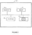
Figure 2 illustrates an example of anetwork device 20 that may be used to implement the embodiments described herein. In one embodiment, thenetwork device 20 is a programmable machine that may be implemented in hardware, software, or any combination thereof. Thenetwork device 20 includes one ormore processors 22,memory 24, network interface (port) 26, andthermal modeling module 28. -
Memory 24 may be a volatile memory or non-volatile storage, which stores various applications, operating systems, modules, and data for execution and use by theprocessor 22. For example, components of the thermal modeling module 28 (e.g., code, logic, firmware, etc.) may be stored in thememory 24.Memory 24 may also store manually input data (e.g., wire gauges and associated cable temperature ratings, measurements, calculated data, or other data, tables, or graphs. Thenetwork device 20 may include any number of memory components. - Logic may be encoded in one or more tangible media for execution by the
processor 22. For example, theprocessor 22 may execute codes stored in a computer-readable medium such asmemory 24. The computer-readable medium may be, for example, electronic (e.g., RAM (random access memory), ROM (read-only memory), EPROM (erasable programmable read-only memory)), magnetic, optical (e.g., CD, DVD), electromagnetic, semiconductor technology, or any other suitable medium. In one example, the computer-readable medium comprises a non-transitory computer-readable medium. Logic may be used to perform one or more functions described below with respect to the flowchart ofFigure 3 . Thenetwork device 20 may include any number ofprocessors 22. - The
network interface 26 may comprise any number of interfaces (linecards, ports) for receiving data or transmitting data to other devices. The interface may be, for example, an interface at thePSE 10 for transmitting power and data to thePD 12, an interface at the PSE for transmitting measurements, data, or risk assessment information to thenetwork device 19, or an internal interface at thePSE 10 for transmitting data to the thermal modeling module 18 (Figures 1 and2 ). Thenetwork interface 26 may include, for example, an Ethernet interface for connection to a computer or network. Theinterface 26 may be configured for PoE, PoF, or similar operation. - It is to be understood that the
network device 20 shown inFigure 2 and described above is only an example and that different configurations of network devices may be used. For example, thenetwork device 20 may further include any suitable combination of hardware, software, algorithms, processors, devices, components, or elements operable to facilitate the capabilities described herein. -
Figure 3 is a flowchart illustrating an overview of a process for modeling thermal characteristics of cables used to transmit power and data, in accordance with one embodiment. Atstep 30, thethermal modeling module 18 receives real-time electrical data (e.g., real-time measurements of relevant parameters) from the PSE 10 (Figures 1 and3 ). In one embodiment, data is extracted from thePSE 10, which may include data from thePDs 12. User input may be received if an intelligent PD is not available. Thethermal modeling module 18 identifies cable adjacencies and characteristics (step 32). In one embodiment, thePSE 10 may use a TDR to determine the cable length at each port. Thethermal modeling module 18 may use voltage, current, and cable length to determine wire gauge using a calculated resistance. If thePD 12 is not able to provide V_in (voltage at PD), the wire gauge may be provided by user input. As described below, cable adjacencies (e.g., arrangement of cables within a bundle, bundle size) may be identified by transmitting a pulse at thePSE 10 and then measuring an E field (pulsed field strength) at surroundingcables 14 to detect adjacent cables. Thethermal modeling module 18 may use the wire gauge data, cable adjacencies, and current, voltage, and power data to calculate thermal characteristics for the cables (step 34). The thermal characteristics may include, for example, thermal rise, maximum power, and overall end-to-end cable health. If a thermal rise at one of the cables exceeds a specified threshold (step 36), thethermal modeling module 18 may take action to reduce the risk of unsafe operation at the cable (step 38). This may include, for example, identifying the cable in a risk assessment table, graphical image, alert, alarm, message, or other indication presented to a user, or preventing operation of the port connected to the cable. Thethermal modeling module 18 may, for example, generate a table or image to indicate cable health for a selected power level and environment for a cable or bundle of cables, as well as generate alarm states (e.g., lights) and messages (e.g., syslog). The thermal rise may refer to a specific temperature, delta temperature, change in temperature (e.g., percent or increase above a baseline temperature), or a rise in temperature over a period of time. - It is to be understood that the process shown in
Figure 3 and described above is only an example and that steps may be added, removed, or combined, without departing from the scope of the embodiments. - The following provides examples for determining wire gauge, bundle size, and cable adjacencies, and presenting data and thermal modeling results to a user.
- In one or more embodiments, wire gauge calculations may be made using V_out (voltage at port of PSE), V_in (voltage at PD), I_individual_cable (current of cable), and TDR_m (cable length). In one example, calculations are performed assuming no connector loss. The resistance calculations may be performed as follows:


- The user may enter the basic wire gauge for the assessment calculations if there is not an intelligent PD to provide V_in.
-
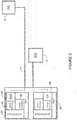
Figure 4 illustrates an example of aPSE 40 that may be used to provide measurements for use in automatically calculating cable adjacency. In the example shown inFigure 4 , thePSE 40 includes two PHY (circuitry for physical layer functions) each having a SerDes 41 (Serializer/Deserializer), asignal receiver 44, and asignal generator 46. ThePSE 40 may comprise any number of ports and corresponding components. In one embodiment, a 1MHz (or any other frequency) pulse is transmitted by thesignal generator 46. The pulse is used to automatically determine cable to cable proximity by calculating a measured field strength (E Field 48) at thereceiver 44. The pulse may be used to track a cable tied to a particular port or switch within a cable bundle referenced to the transmitting port. The pulse may be used, for example within a switch or router during bring up. The 1MHz pulse cannot be used to determine cable proximity between switches in a network or in a situation wherein a data center is running production traffic and a new switch or new cable plant is added. In this case, a packet pulse generator may be used as shown inFigure 5 . -
Figure 5 illustrates a plurality ofPSEs SerDes 51,signal receiver 54 andsignal generator 56, as previously described. The PSEs may communicate with one another over an Ethernet command port communications plane or over a data plane, for example. The packet pulse generator is a specific packet type (packet 55 inFigure 5 ) transmitted instead of idle packets and with a higher energy content achieved by increasing the transmitted signal. Thepacket 55 is detected and thereceiver 54 calculates the cable to cable distance based on the field strength (E Field 58). In the example shown inFigure 5 ,PSE 50b generates thepacket 55 and thefield strength 58 is measured byPSE 50a. The packet pulse generator allows the equipment and cable plant to change over time with constant - (or periodic) updates to the cable-to-cable adjacency within the data center or office environment.
- In one embodiment, the packet pulse generator carries switch IP (Internet Protocol) address and port ID (identifier) so that adjacent switches in the data center can identify where the packet is sourced from and return the received calculation for each port on the switch receiving or recognizing the packet. In one example, the
packet 55 includes the source equipment IP address (e.g., IP address for Ethernet console port or command control panel), source equipment definition (e.g., what kind of switching or routing equipment), source port (e.g., port number, port power capability, port speed capability), signal data definition (e.g., data packet type (FFFF0000, FF00, AA55, etc.)), and data (e.g., as many bytes as possible of the signal data definition). - The pulsing and high frequency tests described above may be used to detect cable architecture (e.g., cable bundling, cable adjacency, bundle size) and basic dielectric calculations may be used to determine cable insulation type. In one example for a 96 port switch, a source wire pulse may be transmitted on one port and the pulse field strength measured on 95 ports. This process may be repeated through 96 ports or a fewer number of ports. In another example, a pulse may be sent on only a portion of the ports until an arrangement of the cables is identified. The cable bundling may be determined by using field strength measurements to determine cable location and cable adjacency. For example, finite element analysis and a convergence algorithm may be used to determine cable-to-cable proximity. In order to detect shielded foil, the pulse strength may be increased on a closest pair to determine if a change indicates shielded or not shielded. The measured field strength will increase with a smaller factor with a shielded cable. An algorithm output may be used to determine the proximity of cables and build a table.
- It is to be understood that the methods and systems described above for determining cable adjacency and bundle characteristics are only examples and that other devices or methods may be used without departing from the scope of the embodiments. Also, if bundle characteristics are known, this information may be manually input to the thermal modeling system. In one or more embodiments, both the 1MHz pulse and packet pulse generator may be used to determine cable adjacencies. For example, the 1MHz pulse may be used during bring up and the packet pulse generator used for periodic updates.
-
Figure 6 illustrates an embodiment that may be used to determine cable length and health. In the example shown inFigure 6 ,PSE 60 includes aSerDes 61,signal receiver 64, TDR (Time Domain Reflectometer) 65, andsignal generator 66. TheTDR 65 may be used to determine the cable length for any port, which may be used to calculate wire gauge (e.g., AWG). If the voltage at thePD 12 is known by thePSE 60, this may be used in conjunction with cable length to determine cable AWG per port, as previously described. TheTDR 65 may also be used to evaluate and determine the cable segments and connection quality. When the PHY detects a cable is connected, a TDR process may be performed to determine the basic cable layout. TDR data may provide, for example, cable length and maximum loss, number of cable segments (length of cable segments and loss per segment, connector count and loss), and identification of cable anomalies. During a TDR process, a cable health assessment may be performed based on losses in the cable. The health assessment may determine the relative loss at each segment (conductor in a particular length of cable) and at each segment point (e.g., RJ45 connector or other type of connector). Using the defined wire gauge calculations, each cable segment in the entire cable length may be evaluated for maximum conductor current. Each connector may be evaluated for its ability to handle the port conductor current. The health assessment along with overall wire gauge calculations may be used to determine the maximum conductor current of an end-to-end cable. In one embodiment, transmit and receive equalization sequences or channel operating margin may be used in place of TDR. - As shown in
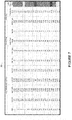
Figures 7 ,8 , and9 , tables 70, 80, and 90 may be created from automatically generated data, manually entered data, and calculations. The table 70 shown inFigure 7 is based on smart PDs, which are configured to measure their input port voltage. The table 80 shown inFigure 8 is based on a Vpd calculated by the PSE. The table 90 shown inFigure 9 is based on smart PDs and automatically gathered cable bundle information. - Referring first to
Figure 7 , for each port at the PSE 10 (e.g., 1-24), the table 70 includes Vpse (V_out), Iport (I_individual_cable), Pport (power_port), Vpd (V_in), TDR (length), Cable AWG (wire gauge), Cable Temp Rating, Bundle (bundle containing cable (e.g., A, B)), Pcable (calculated power dissipated by (or in) the cable), Thermal Rise, and Cable Thermal Status. ThePSE 10 measures Iport, Vpse, Pport, and TDR (to determine cable length) (Figures 1 and7 ). ThePSE 10 measures the real-time current in the cable and the real-time output voltage at the PSE. In one or more embodiments, thePD 12 measures its port voltage and sends it to thePSE 10 viaLayer 2. The user may input the cable temperature rating for each AWG, and the bundle in which the cable is located. This information may be input at theGUI 11 at the networkoperations center device 19, for example, and stored at thethermal modeling module 18. The thermal modeling module 18 (atPSE 10 or network device 19) calculates Pcable based on a combination of Iport and Vpd. The thermal rise may be calculated based on Iport and bundle size. The thermal rise calculations may take into account, for example, cable characteristics (e.g., gauge, area, length, material, insulation type), location (e.g., cable adjacency, bundle location, bundle size), electrical characteristics (e.g., current, voltage, resistance, power), thermal properties (e.g., conductive and convective properties of cable, environment (air gaps, bundling contact, maximum expected ambient temperature at location of cable routing)), or any combination of these or other variables. - The cable thermal status is based on the calculated thermal rise and maximum temperature rating of the cable and may be represented, for example, as a color (e.g., green (safe operating condition), yellow (approaching unsafe operating condition), red (unsafe operating condition)) based on a specified limit or threshold. The threshold may be based on standard temperature limits for the cable or may be user defined. Cable health may be determined based on an expected Pcable based on Iport, Vport, and TDR as compared to Pcable calculated using Vpd.
- Referring now to
Figure 8 , the table 80 shows an example of a risk assessment table for a system in which the PDs are not configured to measure port voltage and provide Vpd. The Vpd column in table 80 is moved from the automatically gathered data (in table 70) to the calculated data. As previously described, thePSE 10 measures Iport, Vport, Pport, and TDR (to measure cable length). A user may input AWG of cable conductors, the cable temperature rating, and the bundle containing the cable. The thermal modeling module 18 (at PSE or other network device 19) may calculate: Vpd based on Iport, Vport, cable length, and AWG; Pcable based on combination of Iport and Vpd; and thermal rise based on Iport and bundle size. The cable thermal status is based on thermal rise and may be indicated as green, yellow, or red, as described above. The cable health cannot be determined without the help of the PD. - The table 90 in
Figure 9 illustrates an automated case in which the smart PDs provide the port voltage (Vpd) and the PSE uses a signal or packet pulse (as described above with respect toFigures 4 and5 ) to automatically determine cable bundle configuration. In this example, data including Vpse, Iport, Pport, Vpd, TDR, Cable AWG, and Bundle information is automatically gathered. The cable power (Pcable) and resulting thermal rise are calculated. As previously described, a cable thermal status column is provided to indicate the health of the cable based on thermal rise thresholds. - It is to be understood that the tables 70, 80, and 90 shown in
Figures 7 ,8 , and9 , respectively, are only examples and that different columns or data may be included or different formats used without departing from the scope of the embodiments. Also, as described above, different data may be automatically gathered or calculated based on system configuration or capability of the devices. -
Figure 10 illustrates an example of a customer risk assessmentgraphical image 100. In this example, an indication is provided for each cable with respect to the risk/health assessment table. As shown inFigure 10 , one cable is identified as "Health: Good, 22AGW, P_c=2.3W, Trise=6degC" and another cable is identified as "Health: max current exceeded, 24AGW, P_c=10.2W, Trise=12degC". Thegraphical view 100 shown inFigure 10 may be available on a customer screen (e.g.,GUI 11 at networkoperations center device 19 inFigure 1 ) or on an equipment display screen. - It is to be understood that the tables 70, 80, 90 shown in
Figures 7 ,8 , and9 and thegraphical image 100 shown inFigure 10 are only examples and that different data, more or less data, or any combination or presentation of data may be provided in the tables or shown in the graphical view. A GUI may allow a user to select how much information or details are presented and how they are presented (e.g., table, image). Also, the user may select to view only a portion of a cable plant, one or more cable plants, or only cables or cable plants with thermal or power issues. - In addition to (or in place of) the table 70, 80, 90 or schematic 100, the
thermal modeling module 18 may transmit one or more alerts (alarm. message, syslog, etc.) when a specified threshold has been reached (e.g., thermal rise above a specified limit, maximum current or power exceeded in one or more cables). For example, thethermal modeling module 18 may determine or user input provided to define appropriate thresholds for allowable temperature rise in a cable for safe operation per port. In one example, a red cable thermal status may prevent the port from operating and a yellow cable thermal status may only allow the port to operate with user intervention. In one embodiment, the GUI may allow for a red override. The user may set the green/yellow/red threshold as appropriate for their cable plant configuration. In one embodiment, thethermal modeling module 18 may generate a flag based on worst case PD classification current. The alarm conditions may include, for example, a strict mode in which thePSE 10 monitors real-time PD currents and enforces a current limit (i.e., shuts down port when current limit is exceeded), and a non-strict mode in which the PSE monitors real-time PD currents and generates an alarm when a current limit is exceeded. The alarm and assessment information may be displayed, for example, on a system display panel or customer interface and provide an indication that attention is needed (e.g., blue attention LED (Light Emitting Diode), syslog message sent through the Ethernet control interface port to the network operations center). - As can be observed from the foregoing, the embodiments described herein may provide many advantages. For example, one or more embodiments may be used to prevent the unwanted heating of cables (e.g., individual cables, bundle of cables) in communications cables where power is delivered over the cables to a powered device. The calculations may be done at installation and continued in real-time during idle packet transfer of the communications circuit, for example. Alarm conditions, attention lights, LCD (Liquid Crystal Display), and messaging may be used to alert the end user in the event an unwanted amount of power beyond the ability of the cable and cable environment is requested by the PD. In one or more embodiments, the PSE port may automatically limit the power available for delivery based on the ability of the cable to safely deliver the required current, and thereby prevent serious damage to the cable plant, building, or user. The embodiments may be used, for example, by network engineers who manage networks with a significant deployment of PoE or PoF powered devices to provide a warning of deployment scenarios where the self-heating of cables could jeopardize the data integrity of the cables. The system may be used for long term planning in a cable plant, for example. One or more embodiments allow a network engineer to simply review the cable plant health assessment, which provides a more accurate assessment than may be provided with visual inspection and also saves a significant amount of time.
- Although the method and apparatus have been described in accordance with the embodiments shown, one of ordinary skill in the art will readily recognize that there could be variations made to the embodiments without departing from the scope of the invention. Accordingly, it is intended that all matter contained in the above description and shown in the accompanying drawings shall be interpreted as illustrative and not in a limiting sense.
- Embodiments are described in the following clauses:-
- 1. A method comprising:
- receiving at a thermal modeling module, data from a Power Sourcing Equipment device (PSE) for cables extending from the PSE to Powered Devices (PDs), the cables configured to transmit power and data from the PSE to the PDs;
- calculating at the thermal modeling module, thermal characteristics for the cables based on the data; and
- identifying a thermal rise above a specified threshold at one of the cables;
- wherein the data comprises real-time electrical data for the cables.
- 2. The method of clause 1 wherein the data comprises voltage and current at ports of the PSE connected to the cables.
- 3. The method of
clause 1 or 2 further comprising identifying at the thermal modeling module a wire gauge of one or more of the cables based on measurements at the PSE and PD. - 4. The method of clause 3 further comprising measuring cable length using a time domain reflectometer, wherein the cable length is used to calculate the wire gauge.
- 5. The method of clause 3 or 4 wherein the data comprises input voltage at the PDs.
- 6. The method of any of clauses 1 to 5 further comprising detecting adjacent cables within a cable bundle by measuring a field strength at one or more of the cables.
- 7. The method of clause 6 wherein detecting adjacent cables comprises transmitting a pulse on one of the cables connected to the PSE and measuring the field strength at one of the cables connected to a signal receiver at the PSE.
- 8. The method of clause 6 wherein detecting adjacent cables comprises measuring the field strength at one of the cables connected to the PSE based on a packet pulse transmitted on one of the cables connected to another PSE.
- 9. The method of any of clauses 1 to 8 further comprising limiting power output at a port of the PSE connected to the cable identified as having said thermal rise above the specified threshold.
- 10. The method of any of clauses 1 to 9 further comprising generating a graphical image indicating a thermal status for one or more of the cables.
- 11. The method of any of clauses 1 to 10 further comprising generating a risk assessment table comprising the data and said thermal rise for each of the cables.
- 12. An apparatus comprising:
- an interface for receiving data from a Power Sourcing Equipment device (PSE) for cables extending from the PSE to Powered Devices (PDs), the cables configured to transmit power and data from the PSE to the PDs, the data comprising real-tin 1e electrical data for the cables;
- a processor for calculating them 1al characteristics for the cables based on the data and identifying a thermal rise above a specified threshold at one of the cables; and
- memory for storing wire gauges and associated cable temperature ratings.
- 13. The apparatus of
clause 12 wherein the data comprises voltage and current at ports of the PSE connected to the cables and input voltage at each of the PDs. - 14. The apparatus of
clause - 15. The apparatus of any of
clauses 12 to 14 wherein the processor is configured to detect adjacent cables within a cable bundle by measuring a field strength at one or more of the cables. - 16. The apparatus of any of
clauses 12 to 15 wherein the processor is configured to limit power output at a port of the PSE connected to the cable identified as having said thermal rise above the specified threshold. - 17. The apparatus of any of
clauses 12 to 16 wherein the processor is configured to generate graphics to indicate said thermal characteristics for the cables to provide a risk assessment for a cable plant comprising the cables. - 18. The apparatus of any of
clauses 12 to 17 wherein the apparatus comprises a module located at the PSE and the interface comprises an internal interface. - 19. The apparatus of any of
clauses 12 to 18 wherein the apparatus comprises a network device in communication with the PSE. - 20. Logic encoded on one or more non-transitory computer readable media for execution and when executed by a processor operable to:
- process data from a Power Sourcing Equipment device (PSE) for cables extending from the PSE to Powered Devices (PDs), the cables configured to transmit power and data from the PSE to the PDs, the data comprising real-time electrical data for the cables;
- calculate thermal characteristics for the cables based on the data; and
- identify a thermal rise above a specified threshold at one of the cables.
- 21. Apparatus comprising:
- means for receiving at a thermal modeling module, data from a Power Sourcing Equipment device (PSE) for cables extending from the PSE to Powered Devices (PDs), the cables configured to transmit power and data from the PSE to the PDs;
- means for calculating at the thermal modeling module, thermal characteristics for the cables based on the data; and
- means for identifying a thermal rise above a specified threshold at one of the cables;
- wherein the data comprises real-time electrical data for the cables.
- 22. The apparatus according to
clause 21 further comprising means for implementing the method according to any ofclauses 2 to 11. - 23. A computer program, computer program product or computer readable medium comprising instructions which, when executed by a computer, cause the computer to carry out the steps of the method of any of clauses 1 to 11.
Claims (15)
- A method comprising:receiving at a thermal modeling module, data from a Power Sourcing Equipment device (PSE) for cables extending from the PSE to Powered Devices (PDs), the cables configured to transmit power and data from the PSE to the PDs;identifying at the thermal modeling module a wire gauge of one or more of the cables based on measurements at the PSE and PD;calculating at the thermal modeling module, thermal characteristics for the cables based on the data and the wire gauge; andidentifying a thermal rise above a specified threshold at one of the cables;wherein the data comprises real-time electrical data for the cables.
- The method of claim 1 wherein the data comprises voltage and current at ports of the PSE connected to the cables.
- The method of claim 1 or 2 further comprising measuring cable length using a time domain reflectometer, wherein the cable length is used to calculate the wire gauge.
- The method of any preceding claim wherein the data comprises input voltage at the PDs.
- The method of any preceding claim further comprising identifying cable adjacencies at the thermal modelling module.
- The method of claim 5 wherein the identifying cable adjacencies comprises detecting adjacent cables within a cable bundle by measuring a field strength at one or more of the cables.
- The method of claim 6 wherein detecting adjacent cables comprises transmitting a pulse on one of the cables connected to the PSE and measuring the field strength at one of the cables connected to a signal receiver at the PSE.
- The method of claim 6 wherein detecting adjacent cables comprises measuring the field strength at one of the cables connected to the PSE based on a packet pulse transmitted on one of the cables connected to another PSE.
- The method of any of claims 1 to 8 further comprising limiting power output at a port of the PSE connected to the cable identified as having said thermal rise above the specified threshold.
- The method of any of claims 1 to 9 further comprising generating a graphical image indicating a thermal status for one or more of the cables.
- The method of any of claims 1 to 10 further comprising generating a risk assessment table comprising the data and said thermal rise for each of the cables.
- Logic encoded on one or more non-transitory computer readable media for execution and when executed by a processor operable to perform a method according to any of claims 1 to 11.
- Apparatus comprising:means for receiving at a thermal modeling module, data from a Power Sourcing Equipment device (PSE) for cables extending from the PSE to Powered Devices (PDs), the cables configured to transmit power and data from the PSE to the PDs;means for identifying at the thermal modeling module a wire gauge of one or more of the cables based on measurements at the PSE and PD;means for calculating at the thermal modeling module, thermal characteristics for the cables based on the data and the wire gauge; andmeans for identifying a thermal rise above a specified threshold at one of the cables;wherein the data comprises real-time electrical data for the cables.
- The apparatus of claim 13, further comprising means for implementing the method according to any of claims 2 to 11.
- A computer program, computer program product or computer readable medium comprising instructions which, when executed by a computer, cause the computer to carry out the steps of the method of any of claims 1 to 11.
Applications Claiming Priority (3)
| Application Number | Priority Date | Filing Date | Title |
|---|---|---|---|
| US15/604,344 US10809134B2 (en) | 2017-05-24 | 2017-05-24 | Thermal modeling for cables transmitting data and power |
| EP18731242.6A EP3632039B1 (en) | 2017-05-24 | 2018-05-11 | Thermal modeling for cables transmitting data and power |
| PCT/US2018/032250 WO2018217476A1 (en) | 2017-05-24 | 2018-05-11 | Thermal modeling for cables transmitting data and power |
Related Parent Applications (2)
| Application Number | Title | Priority Date | Filing Date |
|---|---|---|---|
| EP18731242.6A Division EP3632039B1 (en) | 2017-05-24 | 2018-05-11 | Thermal modeling for cables transmitting data and power |
| EP18731242.6A Division-Into EP3632039B1 (en) | 2017-05-24 | 2018-05-11 | Thermal modeling for cables transmitting data and power |
Publications (2)
| Publication Number | Publication Date |
|---|---|
| EP3836483A1 true EP3836483A1 (en) | 2021-06-16 |
| EP3836483B1 EP3836483B1 (en) | 2023-03-01 |
Family
ID=62599683
Family Applications (2)
| Application Number | Title | Priority Date | Filing Date |
|---|---|---|---|
| EP18731242.6A Active EP3632039B1 (en) | 2017-05-24 | 2018-05-11 | Thermal modeling for cables transmitting data and power |
| EP21156406.7A Active EP3836483B1 (en) | 2017-05-24 | 2018-05-11 | Thermal modeling for cables transmitting data and power |
Family Applications Before (1)
| Application Number | Title | Priority Date | Filing Date |
|---|---|---|---|
| EP18731242.6A Active EP3632039B1 (en) | 2017-05-24 | 2018-05-11 | Thermal modeling for cables transmitting data and power |
Country Status (5)
| Country | Link |
|---|---|
| US (2) | US10809134B2 (en) |
| EP (2) | EP3632039B1 (en) |
| CN (1) | CN110663219B (en) |
| CA (1) | CA3063101C (en) |
| WO (1) | WO2018217476A1 (en) |
Cited By (1)
| Publication number | Priority date | Publication date | Assignee | Title |
|---|---|---|---|---|
| CN114039802A (en) * | 2021-09-18 | 2022-02-11 | 深圳市联洲国际技术有限公司 | Data processing method, expansion circuit, system, device and storage medium |
Families Citing this family (23)
| Publication number | Priority date | Publication date | Assignee | Title |
|---|---|---|---|---|
| US10809134B2 (en) * | 2017-05-24 | 2020-10-20 | Cisco Technology, Inc. | Thermal modeling for cables transmitting data and power |
| US11054457B2 (en) | 2017-05-24 | 2021-07-06 | Cisco Technology, Inc. | Safety monitoring for cables transmitting data and power |
| WO2018234101A1 (en) * | 2017-06-22 | 2018-12-27 | Philips Lighting Holding B.V. | Optical fibre enhanced poe network |
| US11093012B2 (en) | 2018-03-02 | 2021-08-17 | Cisco Technology, Inc. | Combined power, data, and cooling delivery in a communications network |
| US10281513B1 (en) | 2018-03-09 | 2019-05-07 | Cisco Technology, Inc. | Verification of cable application and reduced load cable removal in power over communications systems |
| JP6992737B2 (en) * | 2018-12-14 | 2022-01-13 | オムロン株式会社 | Design support equipment and design support program |
| US10790997B2 (en) | 2019-01-23 | 2020-09-29 | Cisco Technology, Inc. | Transmission of pulse power and data in a communications network |
| US11061456B2 (en) | 2019-01-23 | 2021-07-13 | Cisco Technology, Inc. | Transmission of pulse power and data over a wire pair |
| US10680836B1 (en) | 2019-02-25 | 2020-06-09 | Cisco Technology, Inc. | Virtualized chassis with power-over-Ethernet for networking applications |
| US11456883B2 (en) | 2019-03-13 | 2022-09-27 | Cisco Technology, Inc. | Multiple phase pulse power in a network communications system |
| US11159335B2 (en) * | 2019-08-06 | 2021-10-26 | Cisco Technology, Inc. | Controller-based management of noncompliant power over ethernet devices |
| US11063630B2 (en) | 2019-11-01 | 2021-07-13 | Cisco Technology, Inc. | Initialization and synchronization for pulse power in a network system |
| US11252811B2 (en) | 2020-01-15 | 2022-02-15 | Cisco Technology, Inc. | Power distribution from point-of-load with cooling |
| US11853138B2 (en) | 2020-01-17 | 2023-12-26 | Cisco Technology, Inc. | Modular power controller |
| US11543844B2 (en) | 2020-02-25 | 2023-01-03 | Cisco Technology, Inc. | Method and apparatus for transmitting power and data in a multi-drop architecture |
| US11438183B2 (en) | 2020-02-25 | 2022-09-06 | Cisco Technology, Inc. | Power adapter for power supply unit |
| US11637497B2 (en) | 2020-02-28 | 2023-04-25 | Cisco Technology, Inc. | Multi-phase pulse power short reach distribution |
| US11307368B2 (en) | 2020-04-07 | 2022-04-19 | Cisco Technology, Inc. | Integration of power and optics through cold plates for delivery to electronic and photonic integrated circuits |
| US11320610B2 (en) | 2020-04-07 | 2022-05-03 | Cisco Technology, Inc. | Integration of power and optics through cold plate for delivery to electronic and photonic integrated circuits |
| EP4172581A1 (en) * | 2020-06-25 | 2023-05-03 | SCHEMMANN, Marcel | Current load management for temperature control in a cable duct |
| US11582048B2 (en) | 2020-07-17 | 2023-02-14 | Cisco Technology, Inc. | Bi-directional power over ethernet for digital building applications |
| US11708002B2 (en) | 2020-08-03 | 2023-07-25 | Cisco Technology, Inc. | Power distribution and communications for electric vehicle |
| US11745613B2 (en) | 2020-08-26 | 2023-09-05 | Cisco Technology, Inc. | System and method for electric vehicle charging and security |
Citations (4)
| Publication number | Priority date | Publication date | Assignee | Title |
|---|---|---|---|---|
| EP1936861A1 (en) * | 2006-12-19 | 2008-06-25 | Broadcom Corporation | System and method for controlling power delivered to a powered device based on cable characteristics |
| WO2010053542A2 (en) * | 2008-11-08 | 2010-05-14 | Sensortran, Inc. | System and method for determining characteristics of power cables using distributed temperature sensing systems |
| US20120317426A1 (en) * | 2011-06-09 | 2012-12-13 | Andrew Llc | Distributed antenna system using power-over-ethernet |
| EP2693688A1 (en) * | 2012-08-03 | 2014-02-05 | Broadcom Corporation | Cable imbalance diagnostics between channels that include wire pairs for power over ethernet transmission |
Family Cites Families (227)
| Publication number | Priority date | Publication date | Assignee | Title |
|---|---|---|---|---|
| US3335324A (en) | 1965-10-06 | 1967-08-08 | Westinghouse Air Brake Co | Fail-safe continuous ground monitoring circuit |
| US3962529A (en) | 1970-10-07 | 1976-06-08 | Sumitomo Electric Industries, Ltd. | Evaporative cooling power cable line |
| EP0191482B1 (en) | 1985-02-12 | 1990-07-25 | Hitachi Metals, Ltd. | Dc-dc converter |
| US4997388A (en) | 1989-08-28 | 1991-03-05 | Amp Incorporated | Electrical tap connector |
| US5827267A (en) | 1992-02-18 | 1998-10-27 | Angeion Corporation | Cooled multi-fiber medical connector |
| US5652893A (en) | 1994-12-13 | 1997-07-29 | 3Com Corporation | Switching hub intelligent power management |
| US5602387A (en) * | 1995-06-26 | 1997-02-11 | The United States Of America As Represented By The Secretary Of The Air Force | Method of protecting an RF receiver in a hostile electromagnetic environment |
| US6470405B2 (en) | 1995-10-19 | 2002-10-22 | Rambus Inc. | Protocol for communication with dynamic memory |
| US6931183B2 (en) | 1996-03-29 | 2005-08-16 | Dominion Lasercom, Inc. | Hybrid electro-optic cable for free space laser antennas |
| US7237036B2 (en) | 1997-10-14 | 2007-06-26 | Alacritech, Inc. | Fast-path apparatus for receiving data corresponding a TCP connection |
| US6220955B1 (en) | 1998-02-17 | 2001-04-24 | John G. Posa | Combination power and cooling cable |
| US6826368B1 (en) | 1998-10-20 | 2004-11-30 | Lucent Technologies Inc. | Wavelength division multiplexing (WDM) with multi-frequency lasers and optical couplers |
| WO2000027079A1 (en) | 1998-10-30 | 2000-05-11 | Broadcom Corporation | Internet gigabit ethernet transmitter architecture |
| US6643566B1 (en) | 1999-01-12 | 2003-11-04 | Powerdsine Ltd. | System for power delivery over data communication cabling infrastructure |
| US6008631A (en) | 1999-03-18 | 1999-12-28 | International Business Machines Corporation | Synchronous voltage converter |
| US6636538B1 (en) | 1999-03-29 | 2003-10-21 | Cutting Edge Optronics, Inc. | Laser diode packaging |
| US20030214800A1 (en) | 1999-07-15 | 2003-11-20 | Dibene Joseph Ted | System and method for processor power delivery and thermal management |
| US6400579B2 (en) | 2000-03-24 | 2002-06-04 | Slobodan Cuk | Lossless switching DC to DC converter with DC transformer |
| JP3830726B2 (en) | 2000-04-26 | 2006-10-11 | 松下電器産業株式会社 | Thermally conductive substrate, manufacturing method thereof, and power module |
| US6734784B1 (en) | 2000-09-06 | 2004-05-11 | Marshall E. Lester | Zero crossing based powerline pulse position modulated communication system |
| USRE40866E1 (en) | 2000-09-27 | 2009-08-04 | Huron Ip Llc | System, method, and architecture for dynamic server power management and dynamic workload management for multiserver environment |
| CN1209880C (en) | 2001-11-30 | 2005-07-06 | 王德清 | Wideband access transmission entwork as assembly of power supply, telecommunication device, TV set and internet network |
| US6685364B1 (en) | 2001-12-05 | 2004-02-03 | International Business Machines Corporation | Enhanced folded flexible cable packaging for use in optical transceivers |
| US7358745B1 (en) | 2002-06-07 | 2008-04-15 | Marvell International Ltd. | Cable tester |
| US6855881B2 (en) | 2002-06-26 | 2005-02-15 | Bahman Khoshnood | Combined communication and power cable with air cooling for network systems |
| US7254332B2 (en) | 2002-08-06 | 2007-08-07 | Jun-Kook Choi | Wavelength division multiplexing passive optical network system |
| US6851960B2 (en) | 2002-08-29 | 2005-02-08 | Dell Products L.P. | AC adapter connector assembly |
| SE527381C3 (en) | 2003-04-14 | 2006-03-21 | Linnman Elektronik Ab | Common fieldbus for data and energy transfer |
| US6989997B2 (en) | 2003-06-25 | 2006-01-24 | Virginia Tech Intellectual Properties, Inc. | Quasi-resonant DC-DC converters with reduced body diode loss |
| US7492059B2 (en) | 2003-10-16 | 2009-02-17 | Microsemi Corp.—Analog Mixed Signal Group Ltd. | High power architecture for power over ethernet |
| US7583703B2 (en) | 2003-10-23 | 2009-09-01 | Cisco Technology Inc. | System and method for power injection and out of band communications on shared medium |
| US6976885B2 (en) | 2004-03-02 | 2005-12-20 | Mobility Electronics, Inc. | Keyed universal power tip and power source connectors |
| US7212419B2 (en) | 2004-02-24 | 2007-05-01 | Vlt, Inc. | Adaptively configured and autoranging voltage transformation module arrays |
| US7188415B2 (en) * | 2004-04-29 | 2007-03-13 | Carlyle, Inc. | Cable harness breakout assembly method |
| US7603570B2 (en) | 2004-05-13 | 2009-10-13 | Cisco Technology, Inc. | Power delivery over ethernet cables |
| CN100544131C (en) | 2004-06-24 | 2009-09-23 | 摩勒克斯公司 | Jack connector assembly with integrated circuit component that the POE function is provided |
| US7056149B1 (en) | 2004-11-12 | 2006-06-06 | Comarco Wireless Technologies, Inc. | Key coded power adapter connectors |
| US7509505B2 (en) | 2005-01-04 | 2009-03-24 | Cisco Technology, Inc. | Method and system for managing power delivery for power over Ethernet systems |
| US7263245B2 (en) | 2005-03-14 | 2007-08-28 | The Boeing Company | Method and apparatus for optically powering and multiplexing distributed fiber optic sensors |
| US7474704B2 (en) | 2005-03-16 | 2009-01-06 | Cisco Technology, Inc. | Method and apparatus for current sharing ethernet power across four conductor pairs |
| US7473849B2 (en) * | 2005-04-25 | 2009-01-06 | Cable Components Group | Variable diameter conduit tubes for high performance, multi-media communication cable |
| US8184525B2 (en) | 2005-05-25 | 2012-05-22 | Cisco Technology, Inc. | Method and apparatus for detecting and fixing faults in an inline-power capable ethernet system |
| US7586840B2 (en) | 2005-05-25 | 2009-09-08 | Cisco Technology, Inc. | Method and apparatus for detecting and fixing faults in an inline-power capable ethernet system |
| US7593747B1 (en) | 2005-07-01 | 2009-09-22 | Cisco Technology, Inc. | Techniques for controlling delivery of power to a remotely powerable device based on temperature |
| US9189036B2 (en) | 2005-08-19 | 2015-11-17 | Akros Silicon, Inc. | Ethernet module |
| US7940787B2 (en) | 2005-08-30 | 2011-05-10 | Cisco Technology, Inc. | Low-power ethernet device |
| US7265555B2 (en) | 2005-11-09 | 2007-09-04 | Douglas William Batten | Loop impedance meter |
| US8432142B2 (en) | 2006-01-17 | 2013-04-30 | Broadcom Corporation | Power over ethernet controller integrated circuit architecture |
| US7560825B2 (en) | 2006-04-11 | 2009-07-14 | Akros Silicon, Inc. | Network devices for separating power and data signals |
| US7490251B2 (en) | 2006-04-13 | 2009-02-10 | Cisco Technology, Inc. | Method and apparatus for current sharing ethernet power across four conductor pairs using a midspan device |
| US20070288125A1 (en) | 2006-06-09 | 2007-12-13 | Mks Instruments, Inc. | Power Over Ethernet (Poe) - Based Measurement System |
| US20070284946A1 (en) | 2006-06-10 | 2007-12-13 | Steven Andrew Robbins | Passive Power Combiner for Dual Power over Ethernet Sources |
| US8834488B2 (en) | 2006-06-22 | 2014-09-16 | Board Of Regents Of The University Of Nebraska | Magnetically coupleable robotic surgical devices and related methods |
| US7835389B2 (en) | 2006-09-20 | 2010-11-16 | Broadcom Corporation | Method and system for an extended range Ethernet line code using 4B/3B mapping |
| US9515843B2 (en) | 2006-06-22 | 2016-12-06 | Broadcom Corporation | Method and system for link adaptive Ethernet communications |
| US7420355B2 (en) | 2006-07-11 | 2008-09-02 | Artesyn Technologies, Inc. | DC-DC converter with over-voltage protection |
| US7589435B2 (en) | 2006-08-02 | 2009-09-15 | Cisco Technology, Inc. | Reporting power requirements of a powered device |
| US7490996B2 (en) | 2006-08-16 | 2009-02-17 | Sigmund Sommer | Electro-optical plug and receptacle |
| US7471014B2 (en) | 2006-09-01 | 2008-12-30 | Cisco Technology, Inc. | Method and apparatus distributing power to a load in a powered device |
| US7566987B2 (en) | 2006-09-14 | 2009-07-28 | Lutron Electronics Co., Inc. | Method of powering up a plurality of loads in sequence |
| US7915761B1 (en) | 2006-09-27 | 2011-03-29 | Cisco Technology, Inc. | Power injector detection |
| US20080198635A1 (en) | 2007-02-21 | 2008-08-21 | Broadcom Corporation | Pulse width modulated ground/return for powered device |
| US7814346B2 (en) * | 2007-03-12 | 2010-10-12 | Broadcom Corporation | System and method for continual cable thermal monitoring using cable resistance considerations in power over ethernet |
| CN101680718A (en) | 2007-03-14 | 2010-03-24 | 佐尼特结构解决方案有限责任公司 | Air-based cooling for data center rack |
| US8037324B2 (en) | 2007-03-20 | 2011-10-11 | Broadcom Corporation | Power over ethernet connector with integrated power source equipment (PSE) controller supporting high power applications |
| US7921307B2 (en) | 2007-03-27 | 2011-04-05 | Cisco Technology, Inc. | Methods and apparatus providing advanced classification for power over Ethernet |
| US20080276104A1 (en) | 2007-05-01 | 2008-11-06 | Broadcom Corporation | Power source equiment for power over ethernet system with increased cable length |
| DE202007007927U1 (en) | 2007-06-05 | 2007-08-23 | Bürkert Werke GmbH & Co. KG | Hybrid universal distribution system with electrical, fluidic and communication functions |
| US7737704B2 (en) | 2007-06-12 | 2010-06-15 | Broadcom Corporation | System and method for using a PHY to locate a thermal signature in a cable plant for diagnostic, enhanced, and higher power applications |
| US8094452B1 (en) | 2007-06-27 | 2012-01-10 | Exaflop Llc | Cooling and power grids for data center |
| US7813646B2 (en) | 2007-07-11 | 2010-10-12 | RLH Industries, Inc | Power over optical fiber system |
| US7797560B2 (en) * | 2007-07-24 | 2010-09-14 | Broadcom Corporation | System and method for integrated temperature measurement in power over Ethernet applications |
| US8081589B1 (en) | 2007-08-28 | 2011-12-20 | Meru Networks | Access points using power over ethernet |
| US7924579B2 (en) | 2008-02-05 | 2011-04-12 | Cisco Technology, Inc. | Fly-forward converter power supply |
| EP2120443A1 (en) | 2008-05-15 | 2009-11-18 | BRITISH TELECOMMUNICATIONS public limited company | Power supply system |
| US8279883B2 (en) | 2008-07-07 | 2012-10-02 | Broadcom Corporation | High speed isolation interface for PoE |
| US7973538B2 (en) | 2008-08-21 | 2011-07-05 | Cisco Technology, Inc. | Power over ethernet system having hazard detection circuitry to detect potentially hazardous cable conditions |
| US20100052642A1 (en) * | 2008-08-26 | 2010-03-04 | Broadcom Corporation | System and method for using a phy's discovery of cable shielding for power over ethernet current capacity setting and temperature de-rating |
| GB0816721D0 (en) | 2008-09-13 | 2008-10-22 | Daniel Simon R | Systems,devices and methods for electricity provision,usage monitoring,analysis and enabling improvements in efficiency |
| US8712324B2 (en) | 2008-09-26 | 2014-04-29 | Qualcomm Incorporated | Inductive signal transfer system for computing devices |
| US8122266B2 (en) | 2008-11-11 | 2012-02-21 | Cisco Technology, Inc. | Powered communications interface providing low-speed communications between power-sourcing equipment and powered device in non-powered operating mode |
| US8345439B1 (en) | 2008-11-18 | 2013-01-01 | Force10 Networks, Inc. | Modular chassis arrangement with redundant logic power delivery system |
| US7990710B2 (en) | 2008-12-31 | 2011-08-02 | Vs Acquisition Co. Llc | Data center |
| US8205102B2 (en) | 2009-01-05 | 2012-06-19 | Hewlett-Packard Development Company, L.P. | Intelligent power management of an intermediate network device switching circuitry and PoE delivery |
| US8020043B2 (en) | 2009-03-06 | 2011-09-13 | Cisco Technology, Inc. | Field failure data collection |
| US8269622B2 (en) | 2009-03-17 | 2012-09-18 | Jetlun Corporation | Method and system for intelligent energy network management control system |
| US8049484B2 (en) | 2009-03-17 | 2011-11-01 | Cisco Technology, Inc. | Controlling inline power at a powered device |
| US8350538B2 (en) | 2009-04-11 | 2013-01-08 | Cuks, Llc | Voltage step-down switching DC-to-DC converter |
| US8605798B2 (en) | 2009-05-12 | 2013-12-10 | Alfred E. Mann Foundation For Scientific Research | Power and bidirectional data transmission |
| US8284830B2 (en) | 2009-05-12 | 2012-10-09 | Alfred E. Mann Foundation For Scientific Research | Pulse edge demodulation |
| US8369090B2 (en) | 2009-05-12 | 2013-02-05 | Iceotope Limited | Cooled electronic system |
| GB2467808B (en) | 2009-06-03 | 2011-01-12 | Moduleco Ltd | Data centre |
| JP5476872B2 (en) | 2009-09-04 | 2014-04-23 | 株式会社デンソー | Charging state transmitter and external charging system |
| US8781637B2 (en) | 2009-10-27 | 2014-07-15 | Voltserver Inc. | Safe exposed conductor power distribution system |
| CA2684820A1 (en) | 2009-11-06 | 2011-05-06 | Wayne Ernest Conrad | Electrical cord and apparatus using same |
| US8638008B2 (en) | 2009-12-22 | 2014-01-28 | Direct Power Tech Ip, Llc | 380 volt direct current power distribution system for information and communication technology systems and facilities |
| US8358893B1 (en) | 2010-01-14 | 2013-01-22 | Sandia Corporation | Photonic-powered cable assembly |
| EP2367275B2 (en) | 2010-03-18 | 2020-12-23 | MARICI Holdings The Netherlands B.V. | Non-isolated DC - DC converter for solar power plant |
| EP2548186B1 (en) | 2010-03-19 | 2014-11-19 | Moog Inc. | Power over ethernet prioritization system and method for surveillance cameras |
| US8935543B2 (en) | 2010-04-02 | 2015-01-13 | Andrew Llc | Method and apparatus for distributing power over communication cabling |
| US8344246B2 (en) * | 2010-04-06 | 2013-01-01 | Google Inc. | Cooling disc for bundles of current carrying cables |
| US8310089B2 (en) * | 2010-05-03 | 2012-11-13 | Cisco Technology, Inc. | Power sharing network communications device |
| CN201689347U (en) | 2010-05-06 | 2010-12-29 | 谭志明 | POE (Power Over Ethernet) power supply temperature control device |
| US8757270B2 (en) | 2010-05-28 | 2014-06-24 | Statoil Petroleum As | Subsea hydrocarbon production system |
| US8639070B2 (en) | 2010-10-07 | 2014-01-28 | Alcatel Lucent | Optical assembly for a WDM receiver or transmitter |
| EP2643947B1 (en) | 2010-11-24 | 2018-09-19 | Corning Optical Communications LLC | Power distribution module(s) capable of hot connection and/or disconnection for distributed antenna systems, and related power units, components, and methods |
| US8666255B2 (en) | 2010-12-30 | 2014-03-04 | Source Photonics, Inc. | Circuits, architectures, apparatuses, systems, and methods for merging of management and data signals, and for recovery of a management signal |
| US10389235B2 (en) | 2011-05-05 | 2019-08-20 | Psemi Corporation | Power converter |
| CN102158096B (en) | 2011-05-11 | 2013-11-20 | 南京博兰得电子科技有限公司 | Non-isolated resonant converter |
| US8966747B2 (en) | 2011-05-11 | 2015-03-03 | Vlt, Inc. | Method of forming an electrical contact |
| US8768528B2 (en) | 2011-05-16 | 2014-07-01 | Vcharge, Inc. | Electrical thermal storage with edge-of-network tailored energy delivery systems and methods |
| WO2012160825A1 (en) | 2011-05-25 | 2012-11-29 | 日本電気株式会社 | Sensor and receiving device in sensor system |
| US8730673B2 (en) | 2011-05-27 | 2014-05-20 | Lockheed Martin Corporation | Fluid-cooled module for integrated circuit devices |
| US8750710B1 (en) | 2011-07-15 | 2014-06-10 | Cisco Technology, Inc. | System and method for facilitating fiber access transport using pluggable radio frequency optics |
| EP2734906B1 (en) | 2011-07-18 | 2018-12-05 | Hewlett-Packard Development Company, L.P. | Power consumption limit associated with power over ethernet (poe) computing system |
| US8350526B2 (en) | 2011-07-25 | 2013-01-08 | Lightening Energy | Station for rapidly charging an electric vehicle battery |
| US9024473B2 (en) | 2011-08-30 | 2015-05-05 | Linear Technology Corporation | Power combining in power over ethernet systems |
| US20130077923A1 (en) | 2011-09-23 | 2013-03-28 | Tyco Electronics Corporation | Hybrid Cable Assembly |
| US20130079633A1 (en) | 2011-09-23 | 2013-03-28 | Tyco Electronics Corporation | Diagnostic System with Hybrid Cable Assembly |
| US9069151B2 (en) | 2011-10-26 | 2015-06-30 | Corning Cable Systems Llc | Composite cable breakout assembly |
| US20130272721A1 (en) | 2012-04-13 | 2013-10-17 | Alcatel-Lucent Usa, Inc. | Optical network device employing three-level duobinary modulation and method of use thereof |
| US9620941B2 (en) | 2012-06-11 | 2017-04-11 | Commscope, Inc. Of North Carolina | Intelligent telecommunications patching system |
| US9273906B2 (en) | 2012-06-14 | 2016-03-01 | International Business Machines Corporation | Modular pumping unit(s) facilitating cooling of electronic system(s) |
| US10407995B2 (en) | 2012-07-05 | 2019-09-10 | Sdg Llc | Repetitive pulsed electric discharge drills including downhole formation evaluation |
| JP5992058B2 (en) | 2012-07-10 | 2016-09-14 | インテル・コーポレーション | Network system configured to resolve forward error correction in data mode |
| EP2891269B1 (en) | 2012-08-29 | 2016-04-27 | Koninklijke Philips N.V. | Method and apparatus for multiplexed power and data supply via a two-wire data communication cable |
| US9319101B2 (en) | 2012-09-28 | 2016-04-19 | Siemens Industry, Inc. | System and method for ground fault detection in a transformer isolated communication channel of a network device |
| US8872579B2 (en) | 2012-10-23 | 2014-10-28 | Broadcom Corporation | Method and apparatus for current sensing in power over Ethernet (PoE) systems |
| US9026809B2 (en) | 2012-11-05 | 2015-05-05 | Linear Technology Corporation | Polarity correction bridge controller for combined power over ethernet system |
| US9665148B2 (en) | 2012-11-07 | 2017-05-30 | Dell Products L.P. | PoE power distribution system for PoE-powered port extender having multiple data and power inputs |
| US9148982B2 (en) | 2012-11-08 | 2015-09-29 | International Business Machines Corporation | Separate control of coolant flow through coolant circuits |
| US9019895B2 (en) | 2013-01-09 | 2015-04-28 | Qualcomm Incorporated | Methods and apparatus for controlling access points coupled to a common power source |
| US10050389B2 (en) | 2013-01-18 | 2018-08-14 | Mertek Industries, Llc | Field-terminable traceable cables, components, kits, and methods |
| US20160018252A1 (en) * | 2013-03-04 | 2016-01-21 | International Road Dynamics, Inc. | Sensor including electrical transmission-line parameter that changes responsive to vehicular load |
| US20140258742A1 (en) | 2013-03-05 | 2014-09-11 | Ching-Yun CHIEN | Hybrid fiber optic and power over ethernet |
| US20140265550A1 (en) | 2013-03-14 | 2014-09-18 | Raytheon Bbn Technologies Corp. | Redundantly powered and daisy chained power over ethernet |
| US9373963B2 (en) | 2013-05-24 | 2016-06-21 | Raytheon Company | Energy transfer and storage apparatus for delivery of pulsed power |
| US9209981B2 (en) | 2013-06-18 | 2015-12-08 | Linear Technology Corporation | Power over Ethernet on data pairs and spare pairs |
| US9182561B2 (en) * | 2013-08-13 | 2015-11-10 | Corning Cable Systems Llc | Optical fiber cable with cable heating element |
| US10171180B2 (en) | 2013-09-19 | 2019-01-01 | Radius Universal, LLC | Fiber optic communications and power network |
| US20150078740A1 (en) | 2013-09-19 | 2015-03-19 | RADIUS UNIVERSAL, A Limited Liability Company of the State of New York | Fiber optic communications network |
| US9356439B2 (en) | 2013-09-26 | 2016-05-31 | Commscope, Inc. Of North Carolina | Patch cords for reduced-pair ethernet applications having strain relief units that resist rotational loads and related strain relief units and connectors |
| US9727518B2 (en) | 2013-10-10 | 2017-08-08 | Nokia Technologies Oy | Communication control pins in a dual row connector |
| FR3012661B1 (en) * | 2013-10-28 | 2015-12-04 | Labinal | METHOD FOR CHARACTERIZING A TORON OF ELECTRIC CABLES |
| US9640998B2 (en) | 2013-10-29 | 2017-05-02 | Avaya Inc. | AC power over Ethernet |
| US9484771B2 (en) | 2013-11-01 | 2016-11-01 | Juniper Networks, Inc. | Uninterruptable power supply for device having power supply modules with internal automatic transfer switches |
| WO2015106992A1 (en) * | 2014-01-14 | 2015-07-23 | Koninklijke Philips N.V. | Low power standby for a powered device in a power distribution system |
| MX359782B (en) | 2014-01-19 | 2018-10-10 | Voltserver Inc | Digital power network method and apparatus. |
| US9184795B2 (en) | 2014-01-26 | 2015-11-10 | VoltServer, Inc. | Packet energy transfer in-line communications |
| EP3100416B1 (en) | 2014-01-29 | 2019-10-16 | Hewlett-Packard Enterprise Development LP | Managing a number of ethernet links |
| US9634844B2 (en) | 2014-01-30 | 2017-04-25 | Linear Technology Corporation | Detection scheme for four wire pair Power Over Ethernet system |
| US9321362B2 (en) | 2014-02-05 | 2016-04-26 | Tesia Motors, Inc. | Cooling of charging cable |
| US20150333918A1 (en) | 2014-05-15 | 2015-11-19 | Schneider Electric Buildings, Llc | Power over ethernet enabled sensor and sensor network |
| US9638583B2 (en) | 2014-05-21 | 2017-05-02 | Amazon Technologies, Inc. | Virtual data center environmental monitoring system |
| US10007628B2 (en) | 2014-06-18 | 2018-06-26 | Qualcomm Incorporated | Dynamically adjustable multi-line bus shared by multi-protocol devices |
| AU2015280694B2 (en) | 2014-06-23 | 2020-09-10 | Gridbridge, Inc. | Highly flexible, electrical distribution grid edge energy manager and router |
| US11063431B2 (en) | 2014-07-04 | 2021-07-13 | Apparent Labs Llc | Hierarchical and distributed power grid control |
| GB2534259B (en) * | 2014-07-14 | 2021-04-21 | Pismo Labs Technology Ltd | Methods and systems for transmitting data packets |
| US9531551B2 (en) | 2014-08-26 | 2016-12-27 | Cisco Technology, Inc. | Dynamically configurable power-over-ethernet apparatus and method |
| US9618714B2 (en) | 2014-10-14 | 2017-04-11 | David W. Murray | Optical wiring systems and methods |
| CA2964802C (en) | 2014-10-21 | 2018-06-05 | VoltServer, Inc. | Digital power receiver system |
| US9705306B2 (en) | 2014-10-23 | 2017-07-11 | Honeywell International Inc. | Non-isolated power supply output chassis ground fault detection and protection system |
| US10405405B2 (en) | 2014-10-28 | 2019-09-03 | Signify Holding B.V. | Apparatus, method and system for controlling a load device via a power line by using a power negotiation protocol |
| US9853689B2 (en) | 2014-11-07 | 2017-12-26 | VoltServer, Inc. | Packet energy transfer power control elements |
| WO2016073862A2 (en) | 2014-11-07 | 2016-05-12 | Cable Components Group, Llc | Compositions for compounding, extrusion and melt processing of foamable and cellular halogen-free polymers |
| US10031301B2 (en) * | 2014-11-07 | 2018-07-24 | Cable Components Group, Llc | Compositions for compounding, extrusion, and melt processing of foamable and cellular polymers |
| US9967104B2 (en) | 2014-11-19 | 2018-05-08 | Linear Technology Corporation | Detecting ground isolation fault in ethernet PoDL system |
| CA2972901C (en) | 2014-12-31 | 2020-01-14 | Servicenow, Inc. | Failure resistant distributed computing system |
| US9837996B2 (en) | 2015-01-07 | 2017-12-05 | Raytheon Company | Method and apparatus for control of pulsed power in hybrid energy storage module |
| CN104698297B (en) * | 2015-02-09 | 2018-05-04 | 南方电网科学研究院有限责任公司 | A kind of modification method of large scale coaxial cable insulation cable space charge measurement |
| US20160241148A1 (en) | 2015-02-13 | 2016-08-18 | Avogy, Inc. | Method and system for integrated power supply with accessory functions |
| US9713286B2 (en) | 2015-03-03 | 2017-07-18 | International Business Machines Corporation | Active control for two-phase cooling |
| CN106537721B (en) | 2015-03-18 | 2018-05-15 | 艾欧塔工程有限公司 | Power over Ethernet emergency lighting system and the method for detecting its link section power loss |
| CN106159925A (en) | 2015-04-03 | 2016-11-23 | 富士康(昆山)电脑接插件有限公司 | Network surge prevention circuit and apply the network surge prevention device of this circuit |
| US20160294500A1 (en) | 2015-04-03 | 2016-10-06 | John Mezzalingua Associates, LLC | Packet energy transfer powered telecommunications system for macro antenna systems and power distribution system therefor |
| US9985600B2 (en) | 2015-04-03 | 2018-05-29 | Foxconn Interconnect Technology Limited | Printed circuit board assembly for filtering noise of network signal transmission |
| US20160294568A1 (en) | 2015-04-03 | 2016-10-06 | John Mezzalingua Associates, LLC | Packet energy transfer powered telecommunications system for distributed antenna systems and integrated wireless fidelity system |
| US10135626B2 (en) | 2015-04-14 | 2018-11-20 | Avago Technologies General Ip (Singapore) Pte. Ltd. | Power coupling circuits for single-pair ethernet with automotive applications |
| WO2016170184A1 (en) | 2015-04-23 | 2016-10-27 | Danmarks Tekniske Universitet | A three-port direct current converter |
| JP6477220B2 (en) | 2015-05-12 | 2019-03-06 | Tdk株式会社 | Resonant converter and switching power supply |
| US10027471B2 (en) | 2015-06-11 | 2018-07-17 | Avago Technologies General Ip (Singapore) Pte. Ltd. | Synchronization and training stage operation |
| CN204836199U (en) | 2015-07-29 | 2015-12-02 | 杭州海康威视数字技术股份有限公司 | POE power module and be provided with POE power module's cable |
| US10389539B2 (en) | 2015-08-07 | 2019-08-20 | Texas Instruments Incorporated | Turn on method without power interruption redundant power over Ethernet systems |
| US10374813B2 (en) | 2015-08-07 | 2019-08-06 | The Boeing Company | Coupler for power line communication and power-over-ethernet |
| US10128764B1 (en) | 2015-08-10 | 2018-11-13 | Vlt, Inc. | Method and apparatus for delivering power to semiconductors |
| US9874930B2 (en) | 2015-09-03 | 2018-01-23 | Cisco Technology, Inc. | Selection of power in power over ethernet systems |
| WO2017054030A1 (en) | 2015-09-29 | 2017-04-06 | Electrical Engineering Solutions Pty Ltd | A mobile power, data and lighting system |
| CN108292836B (en) | 2015-10-16 | 2020-11-17 | 弗雷德里克·M·福斯特 | Ethernet power supply PoE cable medium communication circuit protection system and method |
| US20170123466A1 (en) | 2015-11-02 | 2017-05-04 | Thomas Craig Carnevale | System Management Device with High-Powered Power Over Ethernet |
| US10318266B2 (en) | 2015-11-25 | 2019-06-11 | Johnson Controls Technology Company | Modular multi-function thermostat |
| CN106817226B (en) | 2015-11-30 | 2019-11-29 | 华为技术有限公司 | A kind of method of supplying power to and PSE based on PoE |
| CN106817225B (en) | 2015-11-30 | 2020-04-21 | 华为技术有限公司 | Power over Ethernet method and apparatus |
| ES2912915T3 (en) | 2016-01-24 | 2022-05-30 | Voltserver Inc | Method and apparatus for parallel operation of packet energy transfer receivers |
| US10671826B2 (en) | 2016-02-08 | 2020-06-02 | Ideal Industries Lighting Llc | Indoor location services using a distributed lighting network |
| WO2017139289A1 (en) | 2016-02-08 | 2017-08-17 | VoltServer, Inc. | Digital electricity transmission system using reversal sensing packet energy transfer |
| EP3211289B1 (en) | 2016-02-26 | 2021-12-15 | Nel Hydrogen A/S | Communication/control system for a hydrogen refuelling system |
| CN205544597U (en) * | 2016-03-18 | 2016-08-31 | 江苏联宏自动化系统工程有限公司 | Multi -functional three -phase power monitoring device |
| GB2548914B (en) | 2016-04-01 | 2019-02-13 | Canon Kk | Power management method of a system made of devices powered over data cable |
| US9912409B2 (en) | 2016-04-12 | 2018-03-06 | Cable Television Laboratories, Inc | Fiber communication systems and methods |
| US9734940B1 (en) | 2016-04-14 | 2017-08-15 | Superior Essex International LP | Communication cables incorporating twisted pair components |
| US9949409B2 (en) | 2016-05-11 | 2018-04-17 | Facebook, Inc. | Modular network switches, associated structures, and associated methods of manufacture and use |
| WO2018017544A1 (en) | 2016-07-18 | 2018-01-25 | Commscope Technologies Llc | Systems and methods for high capacity power delivery to remote nodes |
| US20180024964A1 (en) | 2016-07-19 | 2018-01-25 | Pure Storage, Inc. | Disaggregated compute resources and storage resources in a storage system |
| US20180188712A1 (en) | 2016-07-22 | 2018-07-05 | Michael T. MacKay | Relevance based digital building |
| US10263526B2 (en) | 2016-08-02 | 2019-04-16 | Smart Prong Technologies, Inc. | Electrical circuit for isolated voltage conversion |
| US9953432B2 (en) | 2016-08-17 | 2018-04-24 | David M. Smith | Systems and methods of detecting motion |
| US20180054083A1 (en) | 2016-08-19 | 2018-02-22 | Leviton Manufacturing Co., Inc. | Supplemental power system for power over ethernet lighting luminaries |
| US20180060269A1 (en) | 2016-08-25 | 2018-03-01 | Analog Devices, Inc. | Systems and techniques for remote bus enable |
| CN106249087A (en) | 2016-09-18 | 2016-12-21 | 国网山东省电力公司德州供电公司 | A kind of on-line real time monitoring system and method for cable metal sheath earth lead |
| JP6754652B2 (en) | 2016-09-27 | 2020-09-16 | ルネサスエレクトロニクス株式会社 | Power supply system |
| WO2018081549A1 (en) | 2016-10-31 | 2018-05-03 | VoltServer, Inc. | Digital power multiport battery charging system |
| US10341125B2 (en) | 2016-12-29 | 2019-07-02 | Nexans | Active cooling arrangement for power over ethernet arrangements |
| KR102307999B1 (en) | 2017-03-06 | 2021-09-30 | 엘에스일렉트릭(주) | Device detecting fault of inverter power relay |
| WO2018200817A1 (en) | 2017-04-26 | 2018-11-01 | VoltServer, Inc. | Methods for verifying digital-electricity line integrity |
| US10809134B2 (en) * | 2017-05-24 | 2020-10-20 | Cisco Technology, Inc. | Thermal modeling for cables transmitting data and power |
| US11757664B2 (en) | 2017-08-04 | 2023-09-12 | Electrical Engineering Solutions Pty Limited | PoE system for the distribution of high voltage power, data and lighting and a common mode signalling system incorporated therein |
| US10541758B2 (en) | 2017-09-18 | 2020-01-21 | Cisco Technology, Inc. | Power delivery through an optical system |
| DE102017125265A1 (en) | 2017-10-27 | 2019-05-02 | Phoenix Contact E-Mobility Gmbh | Charging plug and charging station for a motor vehicle |
| US11093012B2 (en) | 2018-03-02 | 2021-08-17 | Cisco Technology, Inc. | Combined power, data, and cooling delivery in a communications network |
| US10732688B2 (en) | 2018-03-09 | 2020-08-04 | Cisco Technology, Inc. | Delivery of AC power with higher power PoE (power over ethernet) systems |
| US10281513B1 (en) | 2018-03-09 | 2019-05-07 | Cisco Technology, Inc. | Verification of cable application and reduced load cable removal in power over communications systems |
| US10631443B2 (en) | 2018-03-12 | 2020-04-21 | Cisco Technology, Inc. | Splitting of combined delivery power, data, and cooling in a communications network |
| US10672537B2 (en) | 2018-03-30 | 2020-06-02 | Cisco Technology, Inc. | Interface module for combined delivery power, data, and cooling at a network device |
| US10958471B2 (en) | 2018-04-05 | 2021-03-23 | Cisco Technology, Inc. | Method and apparatus for detecting wire fault and electrical imbalance for power over communications cabling |
| US10735105B2 (en) | 2018-05-04 | 2020-08-04 | Cisco Technology, Inc. | High power and data delivery in a communications network with safety and fault protection |
| US11038307B2 (en) | 2018-05-25 | 2021-06-15 | Cisco Technology, Inc. | Cable power rating identification for power distribution over communications cabling |
| US10998685B2 (en) * | 2018-11-08 | 2021-05-04 | Cisco Technology, Inc. | Single pair ethernet connector system |
-
2017
- 2017-05-24 US US15/604,344 patent/US10809134B2/en active Active
-
2018
- 2018-05-11 EP EP18731242.6A patent/EP3632039B1/en active Active
- 2018-05-11 CA CA3063101A patent/CA3063101C/en active Active
- 2018-05-11 WO PCT/US2018/032250 patent/WO2018217476A1/en active Application Filing
- 2018-05-11 EP EP21156406.7A patent/EP3836483B1/en active Active
- 2018-05-11 CN CN201880034257.5A patent/CN110663219B/en active Active
-
2020
- 2020-09-16 US US17/022,685 patent/US11519789B2/en active Active
Patent Citations (4)
| Publication number | Priority date | Publication date | Assignee | Title |
|---|---|---|---|---|
| EP1936861A1 (en) * | 2006-12-19 | 2008-06-25 | Broadcom Corporation | System and method for controlling power delivered to a powered device based on cable characteristics |
| WO2010053542A2 (en) * | 2008-11-08 | 2010-05-14 | Sensortran, Inc. | System and method for determining characteristics of power cables using distributed temperature sensing systems |
| US20120317426A1 (en) * | 2011-06-09 | 2012-12-13 | Andrew Llc | Distributed antenna system using power-over-ethernet |
| EP2693688A1 (en) * | 2012-08-03 | 2014-02-05 | Broadcom Corporation | Cable imbalance diagnostics between channels that include wire pairs for power over ethernet transmission |
Cited By (1)
| Publication number | Priority date | Publication date | Assignee | Title |
|---|---|---|---|---|
| CN114039802A (en) * | 2021-09-18 | 2022-02-11 | 深圳市联洲国际技术有限公司 | Data processing method, expansion circuit, system, device and storage medium |
Also Published As
| Publication number | Publication date |
|---|---|
| US11519789B2 (en) | 2022-12-06 |
| US20230122187A1 (en) | 2023-04-20 |
| EP3632039A1 (en) | 2020-04-08 |
| CN110663219A (en) | 2020-01-07 |
| EP3632039B1 (en) | 2021-03-24 |
| CN110663219B (en) | 2021-10-01 |
| CA3063101C (en) | 2023-04-04 |
| EP3836483B1 (en) | 2023-03-01 |
| CA3063101A1 (en) | 2018-11-29 |
| US10809134B2 (en) | 2020-10-20 |
| US20200408608A1 (en) | 2020-12-31 |
| US20180340840A1 (en) | 2018-11-29 |
| WO2018217476A1 (en) | 2018-11-29 |
Similar Documents
| Publication | Publication Date | Title |
|---|---|---|
| US11519789B2 (en) | Thermal modeling for cables transmitting data and power | |
| US11714118B2 (en) | Safety monitoring for cables transmitting data and power | |
| EP3174243B1 (en) | Poe-based power supply method and pse | |
| US7814346B2 (en) | System and method for continual cable thermal monitoring using cable resistance considerations in power over ethernet | |
| EP4221093A1 (en) | High power and data delivery in a communications network with safety and fault protection | |
| EP4351093A1 (en) | Transmission of pulse power and data over a wire pair | |
| CN102396183B (en) | Managed connectivity devices, systems, and methods | |
| CN103069754B (en) | Communication unit, communication system, communication means and recording medium | |
| US9992117B2 (en) | Network apparatus, communication system, abnormal traffic detection method, and program | |
| US10812137B2 (en) | Switch for use with single pair ethernet on four-pair cabling | |
| US11018492B2 (en) | Communications network power provision sensing, monitoring and control | |
| US11982575B2 (en) | Thermal modeling for cables transmitting data and power | |
| CN105703936B (en) | Control method, control device and main control board | |
| US20110313692A1 (en) | Enhanced Intelligent Patch Panel Diagnostic Management | |
| WO2016116022A1 (en) | Method and device for detecting overcurrent of power over ethernet | |
| TWI608705B (en) | Use of transmission network to alarm optical cable abnormality and its computer program product | |
| Escher et al. | Backwards Compatibility of Single Pair Ethernet Cables | |
| CN114844016A (en) | Flexe-based differential protection system, differential protection method and differential protection device | |
| WO2021113837A1 (en) | Iot panel for diagnostics and monitoring of lan cable conductors | |
| Guide | Brocade ICX 6430 and ICX 6450 Stackable Switches |
Legal Events
| Date | Code | Title | Description |
|---|---|---|---|
| PUAI | Public reference made under article 153(3) epc to a published international application that has entered the european phase |
Free format text: ORIGINAL CODE: 0009012 |
|
| STAA | Information on the status of an ep patent application or granted ep patent |
Free format text: STATUS: THE APPLICATION HAS BEEN PUBLISHED |
|
| AC | Divisional application: reference to earlier application |
Ref document number: 3632039 Country of ref document: EP Kind code of ref document: P |
|
| AK | Designated contracting states |
Kind code of ref document: A1 Designated state(s): AL AT BE BG CH CY CZ DE DK EE ES FI FR GB GR HR HU IE IS IT LI LT LU LV MC MK MT NL NO PL PT RO RS SE SI SK SM TR |
|
| STAA | Information on the status of an ep patent application or granted ep patent |
Free format text: STATUS: REQUEST FOR EXAMINATION WAS MADE |
|
| 17P | Request for examination filed |
Effective date: 20211216 |
|
| RBV | Designated contracting states (corrected) |
Designated state(s): AL AT BE BG CH CY CZ DE DK EE ES FI FR GB GR HR HU IE IS IT LI LT LU LV MC MK MT NL NO PL PT RO RS SE SI SK SM TR |
|
| GRAP | Despatch of communication of intention to grant a patent |
Free format text: ORIGINAL CODE: EPIDOSNIGR1 |
|
| STAA | Information on the status of an ep patent application or granted ep patent |
Free format text: STATUS: GRANT OF PATENT IS INTENDED |
|
| RIC1 | Information provided on ipc code assigned before grant |
Ipc: H04L 12/40 20060101ALI20220901BHEP Ipc: H04L 12/10 20060101AFI20220901BHEP |
|
| INTG | Intention to grant announced |
Effective date: 20220920 |
|
| GRAS | Grant fee paid |
Free format text: ORIGINAL CODE: EPIDOSNIGR3 |
|
| GRAA | (expected) grant |
Free format text: ORIGINAL CODE: 0009210 |
|
| STAA | Information on the status of an ep patent application or granted ep patent |
Free format text: STATUS: THE PATENT HAS BEEN GRANTED |
|
| AC | Divisional application: reference to earlier application |
Ref document number: 3632039 Country of ref document: EP Kind code of ref document: P |
|
| AK | Designated contracting states |
Kind code of ref document: B1 Designated state(s): AL AT BE BG CH CY CZ DE DK EE ES FI FR GB GR HR HU IE IS IT LI LT LU LV MC MK MT NL NO PL PT RO RS SE SI SK SM TR |
|
| REG | Reference to a national code |
Ref country code: GB Ref legal event code: FG4D |
|
| REG | Reference to a national code |
Ref country code: CH Ref legal event code: EP Ref country code: AT Ref legal event code: REF Ref document number: 1551775 Country of ref document: AT Kind code of ref document: T Effective date: 20230315 |
|
| REG | Reference to a national code |
Ref country code: DE Ref legal event code: R096 Ref document number: 602018046858 Country of ref document: DE |
|
| REG | Reference to a national code |
Ref country code: IE Ref legal event code: FG4D |
|
| REG | Reference to a national code |
Ref country code: LT Ref legal event code: MG9D |
|
| REG | Reference to a national code |
Ref country code: NL Ref legal event code: MP Effective date: 20230301 |
|
| PG25 | Lapsed in a contracting state [announced via postgrant information from national office to epo] |
Ref country code: RS Free format text: LAPSE BECAUSE OF FAILURE TO SUBMIT A TRANSLATION OF THE DESCRIPTION OR TO PAY THE FEE WITHIN THE PRESCRIBED TIME-LIMIT Effective date: 20230301 Ref country code: NO Free format text: LAPSE BECAUSE OF FAILURE TO SUBMIT A TRANSLATION OF THE DESCRIPTION OR TO PAY THE FEE WITHIN THE PRESCRIBED TIME-LIMIT Effective date: 20230601 Ref country code: LV Free format text: LAPSE BECAUSE OF FAILURE TO SUBMIT A TRANSLATION OF THE DESCRIPTION OR TO PAY THE FEE WITHIN THE PRESCRIBED TIME-LIMIT Effective date: 20230301 Ref country code: LT Free format text: LAPSE BECAUSE OF FAILURE TO SUBMIT A TRANSLATION OF THE DESCRIPTION OR TO PAY THE FEE WITHIN THE PRESCRIBED TIME-LIMIT Effective date: 20230301 Ref country code: HR Free format text: LAPSE BECAUSE OF FAILURE TO SUBMIT A TRANSLATION OF THE DESCRIPTION OR TO PAY THE FEE WITHIN THE PRESCRIBED TIME-LIMIT Effective date: 20230301 Ref country code: ES Free format text: LAPSE BECAUSE OF FAILURE TO SUBMIT A TRANSLATION OF THE DESCRIPTION OR TO PAY THE FEE WITHIN THE PRESCRIBED TIME-LIMIT Effective date: 20230301 |
|
| PGFP | Annual fee paid to national office [announced via postgrant information from national office to epo] |
Ref country code: FR Payment date: 20230624 Year of fee payment: 6 Ref country code: DE Payment date: 20230622 Year of fee payment: 6 |
|
| REG | Reference to a national code |
Ref country code: AT Ref legal event code: MK05 Ref document number: 1551775 Country of ref document: AT Kind code of ref document: T Effective date: 20230301 |
|
| PG25 | Lapsed in a contracting state [announced via postgrant information from national office to epo] |
Ref country code: SE Free format text: LAPSE BECAUSE OF FAILURE TO SUBMIT A TRANSLATION OF THE DESCRIPTION OR TO PAY THE FEE WITHIN THE PRESCRIBED TIME-LIMIT Effective date: 20230301 Ref country code: PL Free format text: LAPSE BECAUSE OF FAILURE TO SUBMIT A TRANSLATION OF THE DESCRIPTION OR TO PAY THE FEE WITHIN THE PRESCRIBED TIME-LIMIT Effective date: 20230301 Ref country code: NL Free format text: LAPSE BECAUSE OF FAILURE TO SUBMIT A TRANSLATION OF THE DESCRIPTION OR TO PAY THE FEE WITHIN THE PRESCRIBED TIME-LIMIT Effective date: 20230301 Ref country code: GR Free format text: LAPSE BECAUSE OF FAILURE TO SUBMIT A TRANSLATION OF THE DESCRIPTION OR TO PAY THE FEE WITHIN THE PRESCRIBED TIME-LIMIT Effective date: 20230602 Ref country code: FI Free format text: LAPSE BECAUSE OF FAILURE TO SUBMIT A TRANSLATION OF THE DESCRIPTION OR TO PAY THE FEE WITHIN THE PRESCRIBED TIME-LIMIT Effective date: 20230301 |
|
| PG25 | Lapsed in a contracting state [announced via postgrant information from national office to epo] |
Ref country code: SM Free format text: LAPSE BECAUSE OF FAILURE TO SUBMIT A TRANSLATION OF THE DESCRIPTION OR TO PAY THE FEE WITHIN THE PRESCRIBED TIME-LIMIT Effective date: 20230301 Ref country code: RO Free format text: LAPSE BECAUSE OF FAILURE TO SUBMIT A TRANSLATION OF THE DESCRIPTION OR TO PAY THE FEE WITHIN THE PRESCRIBED TIME-LIMIT Effective date: 20230301 Ref country code: PT Free format text: LAPSE BECAUSE OF FAILURE TO SUBMIT A TRANSLATION OF THE DESCRIPTION OR TO PAY THE FEE WITHIN THE PRESCRIBED TIME-LIMIT Effective date: 20230703 Ref country code: EE Free format text: LAPSE BECAUSE OF FAILURE TO SUBMIT A TRANSLATION OF THE DESCRIPTION OR TO PAY THE FEE WITHIN THE PRESCRIBED TIME-LIMIT Effective date: 20230301 Ref country code: CZ Free format text: LAPSE BECAUSE OF FAILURE TO SUBMIT A TRANSLATION OF THE DESCRIPTION OR TO PAY THE FEE WITHIN THE PRESCRIBED TIME-LIMIT Effective date: 20230301 Ref country code: AT Free format text: LAPSE BECAUSE OF FAILURE TO SUBMIT A TRANSLATION OF THE DESCRIPTION OR TO PAY THE FEE WITHIN THE PRESCRIBED TIME-LIMIT Effective date: 20230301 |
|
| PGFP | Annual fee paid to national office [announced via postgrant information from national office to epo] |
Ref country code: GB Payment date: 20230620 Year of fee payment: 6 |
|
| PG25 | Lapsed in a contracting state [announced via postgrant information from national office to epo] |
Ref country code: SK Free format text: LAPSE BECAUSE OF FAILURE TO SUBMIT A TRANSLATION OF THE DESCRIPTION OR TO PAY THE FEE WITHIN THE PRESCRIBED TIME-LIMIT Effective date: 20230301 Ref country code: IS Free format text: LAPSE BECAUSE OF FAILURE TO SUBMIT A TRANSLATION OF THE DESCRIPTION OR TO PAY THE FEE WITHIN THE PRESCRIBED TIME-LIMIT Effective date: 20230701 |
|
| REG | Reference to a national code |
Ref country code: DE Ref legal event code: R097 Ref document number: 602018046858 Country of ref document: DE |
|
| REG | Reference to a national code |
Ref country code: CH Ref legal event code: PL |
|
| PLBE | No opposition filed within time limit |
Free format text: ORIGINAL CODE: 0009261 |
|
| STAA | Information on the status of an ep patent application or granted ep patent |
Free format text: STATUS: NO OPPOSITION FILED WITHIN TIME LIMIT |
|
| PG25 | Lapsed in a contracting state [announced via postgrant information from national office to epo] |
Ref country code: MC Free format text: LAPSE BECAUSE OF FAILURE TO SUBMIT A TRANSLATION OF THE DESCRIPTION OR TO PAY THE FEE WITHIN THE PRESCRIBED TIME-LIMIT Effective date: 20230301 |
|
| REG | Reference to a national code |
Ref country code: BE Ref legal event code: MM Effective date: 20230531 |
|
| PG25 | Lapsed in a contracting state [announced via postgrant information from national office to epo] |
Ref country code: SI Free format text: LAPSE BECAUSE OF FAILURE TO SUBMIT A TRANSLATION OF THE DESCRIPTION OR TO PAY THE FEE WITHIN THE PRESCRIBED TIME-LIMIT Effective date: 20230301 Ref country code: MC Free format text: LAPSE BECAUSE OF FAILURE TO SUBMIT A TRANSLATION OF THE DESCRIPTION OR TO PAY THE FEE WITHIN THE PRESCRIBED TIME-LIMIT Effective date: 20230301 Ref country code: LU Free format text: LAPSE BECAUSE OF NON-PAYMENT OF DUE FEES Effective date: 20230511 Ref country code: LI Free format text: LAPSE BECAUSE OF NON-PAYMENT OF DUE FEES Effective date: 20230531 Ref country code: DK Free format text: LAPSE BECAUSE OF FAILURE TO SUBMIT A TRANSLATION OF THE DESCRIPTION OR TO PAY THE FEE WITHIN THE PRESCRIBED TIME-LIMIT Effective date: 20230301 Ref country code: CH Free format text: LAPSE BECAUSE OF NON-PAYMENT OF DUE FEES Effective date: 20230531 |
|
| 26N | No opposition filed |
Effective date: 20231204 |
|
| REG | Reference to a national code |
Ref country code: IE Ref legal event code: MM4A |
|
| PG25 | Lapsed in a contracting state [announced via postgrant information from national office to epo] |
Ref country code: IE Free format text: LAPSE BECAUSE OF NON-PAYMENT OF DUE FEES Effective date: 20230511 |
|
| PG25 | Lapsed in a contracting state [announced via postgrant information from national office to epo] |
Ref country code: IE Free format text: LAPSE BECAUSE OF NON-PAYMENT OF DUE FEES Effective date: 20230511 |