EP3829043A1 - Electronic converter, corresponding lighting system and method of operating an electronic converter - Google Patents
Electronic converter, corresponding lighting system and method of operating an electronic converter Download PDFInfo
- Publication number
- EP3829043A1 EP3829043A1 EP20206854.0A EP20206854A EP3829043A1 EP 3829043 A1 EP3829043 A1 EP 3829043A1 EP 20206854 A EP20206854 A EP 20206854A EP 3829043 A1 EP3829043 A1 EP 3829043A1
- Authority
- EP
- European Patent Office
- Prior art keywords
- input
- voltage
- node
- resistance
- signal
- Prior art date
- Legal status (The legal status is an assumption and is not a legal conclusion. Google has not performed a legal analysis and makes no representation as to the accuracy of the status listed.)
- Withdrawn
Links
Images


Classifications
-
- H—ELECTRICITY
- H02—GENERATION; CONVERSION OR DISTRIBUTION OF ELECTRIC POWER
- H02M—APPARATUS FOR CONVERSION BETWEEN AC AND AC, BETWEEN AC AND DC, OR BETWEEN DC AND DC, AND FOR USE WITH MAINS OR SIMILAR POWER SUPPLY SYSTEMS; CONVERSION OF DC OR AC INPUT POWER INTO SURGE OUTPUT POWER; CONTROL OR REGULATION THEREOF
- H02M1/00—Details of apparatus for conversion
- H02M1/42—Circuits or arrangements for compensating for or adjusting power factor in converters or inverters
- H02M1/4208—Arrangements for improving power factor of AC input
- H02M1/4225—Arrangements for improving power factor of AC input using a non-isolated boost converter
-
- G—PHYSICS
- G01—MEASURING; TESTING
- G01R—MEASURING ELECTRIC VARIABLES; MEASURING MAGNETIC VARIABLES
- G01R21/00—Arrangements for measuring electric power or power factor
- G01R21/06—Arrangements for measuring electric power or power factor by measuring current and voltage
-
- H—ELECTRICITY
- H02—GENERATION; CONVERSION OR DISTRIBUTION OF ELECTRIC POWER
- H02M—APPARATUS FOR CONVERSION BETWEEN AC AND AC, BETWEEN AC AND DC, OR BETWEEN DC AND DC, AND FOR USE WITH MAINS OR SIMILAR POWER SUPPLY SYSTEMS; CONVERSION OF DC OR AC INPUT POWER INTO SURGE OUTPUT POWER; CONTROL OR REGULATION THEREOF
- H02M3/00—Conversion of dc power input into dc power output
- H02M3/01—Resonant DC/DC converters
-
- H—ELECTRICITY
- H02—GENERATION; CONVERSION OR DISTRIBUTION OF ELECTRIC POWER
- H02M—APPARATUS FOR CONVERSION BETWEEN AC AND AC, BETWEEN AC AND DC, OR BETWEEN DC AND DC, AND FOR USE WITH MAINS OR SIMILAR POWER SUPPLY SYSTEMS; CONVERSION OF DC OR AC INPUT POWER INTO SURGE OUTPUT POWER; CONTROL OR REGULATION THEREOF
- H02M3/00—Conversion of dc power input into dc power output
- H02M3/22—Conversion of dc power input into dc power output with intermediate conversion into ac
- H02M3/24—Conversion of dc power input into dc power output with intermediate conversion into ac by static converters
- H02M3/28—Conversion of dc power input into dc power output with intermediate conversion into ac by static converters using discharge tubes with control electrode or semiconductor devices with control electrode to produce the intermediate ac
- H02M3/325—Conversion of dc power input into dc power output with intermediate conversion into ac by static converters using discharge tubes with control electrode or semiconductor devices with control electrode to produce the intermediate ac using devices of a triode or a transistor type requiring continuous application of a control signal
- H02M3/335—Conversion of dc power input into dc power output with intermediate conversion into ac by static converters using discharge tubes with control electrode or semiconductor devices with control electrode to produce the intermediate ac using devices of a triode or a transistor type requiring continuous application of a control signal using semiconductor devices only
- H02M3/33569—Conversion of dc power input into dc power output with intermediate conversion into ac by static converters using discharge tubes with control electrode or semiconductor devices with control electrode to produce the intermediate ac using devices of a triode or a transistor type requiring continuous application of a control signal using semiconductor devices only having several active switching elements
- H02M3/33571—Half-bridge at primary side of an isolation transformer
-
- H—ELECTRICITY
- H05—ELECTRIC TECHNIQUES NOT OTHERWISE PROVIDED FOR
- H05B—ELECTRIC HEATING; ELECTRIC LIGHT SOURCES NOT OTHERWISE PROVIDED FOR; CIRCUIT ARRANGEMENTS FOR ELECTRIC LIGHT SOURCES, IN GENERAL
- H05B45/00—Circuit arrangements for operating light-emitting diodes [LED]
- H05B45/30—Driver circuits
- H05B45/355—Power factor correction [PFC]; Reactive power compensation
-
- H—ELECTRICITY
- H05—ELECTRIC TECHNIQUES NOT OTHERWISE PROVIDED FOR
- H05B—ELECTRIC HEATING; ELECTRIC LIGHT SOURCES NOT OTHERWISE PROVIDED FOR; CIRCUIT ARRANGEMENTS FOR ELECTRIC LIGHT SOURCES, IN GENERAL
- H05B45/00—Circuit arrangements for operating light-emitting diodes [LED]
- H05B45/30—Driver circuits
- H05B45/37—Converter circuits
- H05B45/3725—Switched mode power supply [SMPS]
- H05B45/38—Switched mode power supply [SMPS] using boost topology
-
- H—ELECTRICITY
- H05—ELECTRIC TECHNIQUES NOT OTHERWISE PROVIDED FOR
- H05B—ELECTRIC HEATING; ELECTRIC LIGHT SOURCES NOT OTHERWISE PROVIDED FOR; CIRCUIT ARRANGEMENTS FOR ELECTRIC LIGHT SOURCES, IN GENERAL
- H05B45/00—Circuit arrangements for operating light-emitting diodes [LED]
- H05B45/30—Driver circuits
- H05B45/37—Converter circuits
- H05B45/3725—Switched mode power supply [SMPS]
- H05B45/382—Switched mode power supply [SMPS] with galvanic isolation between input and output
-
- H—ELECTRICITY
- H05—ELECTRIC TECHNIQUES NOT OTHERWISE PROVIDED FOR
- H05B—ELECTRIC HEATING; ELECTRIC LIGHT SOURCES NOT OTHERWISE PROVIDED FOR; CIRCUIT ARRANGEMENTS FOR ELECTRIC LIGHT SOURCES, IN GENERAL
- H05B45/00—Circuit arrangements for operating light-emitting diodes [LED]
- H05B45/30—Driver circuits
- H05B45/37—Converter circuits
- H05B45/3725—Switched mode power supply [SMPS]
- H05B45/39—Circuits containing inverter bridges
-
- H—ELECTRICITY
- H02—GENERATION; CONVERSION OR DISTRIBUTION OF ELECTRIC POWER
- H02M—APPARATUS FOR CONVERSION BETWEEN AC AND AC, BETWEEN AC AND DC, OR BETWEEN DC AND DC, AND FOR USE WITH MAINS OR SIMILAR POWER SUPPLY SYSTEMS; CONVERSION OF DC OR AC INPUT POWER INTO SURGE OUTPUT POWER; CONTROL OR REGULATION THEREOF
- H02M1/00—Details of apparatus for conversion
- H02M1/0003—Details of control, feedback or regulation circuits
- H02M1/0009—Devices or circuits for detecting current in a converter
-
- H—ELECTRICITY
- H02—GENERATION; CONVERSION OR DISTRIBUTION OF ELECTRIC POWER
- H02M—APPARATUS FOR CONVERSION BETWEEN AC AND AC, BETWEEN AC AND DC, OR BETWEEN DC AND DC, AND FOR USE WITH MAINS OR SIMILAR POWER SUPPLY SYSTEMS; CONVERSION OF DC OR AC INPUT POWER INTO SURGE OUTPUT POWER; CONTROL OR REGULATION THEREOF
- H02M1/00—Details of apparatus for conversion
- H02M1/0003—Details of control, feedback or regulation circuits
- H02M1/0012—Control circuits using digital or numerical techniques
-
- H—ELECTRICITY
- H02—GENERATION; CONVERSION OR DISTRIBUTION OF ELECTRIC POWER
- H02M—APPARATUS FOR CONVERSION BETWEEN AC AND AC, BETWEEN AC AND DC, OR BETWEEN DC AND DC, AND FOR USE WITH MAINS OR SIMILAR POWER SUPPLY SYSTEMS; CONVERSION OF DC OR AC INPUT POWER INTO SURGE OUTPUT POWER; CONTROL OR REGULATION THEREOF
- H02M1/00—Details of apparatus for conversion
- H02M1/0048—Circuits or arrangements for reducing losses
-
- H—ELECTRICITY
- H02—GENERATION; CONVERSION OR DISTRIBUTION OF ELECTRIC POWER
- H02M—APPARATUS FOR CONVERSION BETWEEN AC AND AC, BETWEEN AC AND DC, OR BETWEEN DC AND DC, AND FOR USE WITH MAINS OR SIMILAR POWER SUPPLY SYSTEMS; CONVERSION OF DC OR AC INPUT POWER INTO SURGE OUTPUT POWER; CONTROL OR REGULATION THEREOF
- H02M1/00—Details of apparatus for conversion
- H02M1/0067—Converter structures employing plural converter units, other than for parallel operation of the units on a single load
- H02M1/007—Plural converter units in cascade
-
- H—ELECTRICITY
- H02—GENERATION; CONVERSION OR DISTRIBUTION OF ELECTRIC POWER
- H02M—APPARATUS FOR CONVERSION BETWEEN AC AND AC, BETWEEN AC AND DC, OR BETWEEN DC AND DC, AND FOR USE WITH MAINS OR SIMILAR POWER SUPPLY SYSTEMS; CONVERSION OF DC OR AC INPUT POWER INTO SURGE OUTPUT POWER; CONTROL OR REGULATION THEREOF
- H02M3/00—Conversion of dc power input into dc power output
- H02M3/02—Conversion of dc power input into dc power output without intermediate conversion into ac
- H02M3/04—Conversion of dc power input into dc power output without intermediate conversion into ac by static converters
- H02M3/10—Conversion of dc power input into dc power output without intermediate conversion into ac by static converters using discharge tubes with control electrode or semiconductor devices with control electrode
- H02M3/145—Conversion of dc power input into dc power output without intermediate conversion into ac by static converters using discharge tubes with control electrode or semiconductor devices with control electrode using devices of a triode or transistor type requiring continuous application of a control signal
- H02M3/155—Conversion of dc power input into dc power output without intermediate conversion into ac by static converters using discharge tubes with control electrode or semiconductor devices with control electrode using devices of a triode or transistor type requiring continuous application of a control signal using semiconductor devices only
- H02M3/156—Conversion of dc power input into dc power output without intermediate conversion into ac by static converters using discharge tubes with control electrode or semiconductor devices with control electrode using devices of a triode or transistor type requiring continuous application of a control signal using semiconductor devices only with automatic control of output voltage or current, e.g. switching regulators
-
- Y—GENERAL TAGGING OF NEW TECHNOLOGICAL DEVELOPMENTS; GENERAL TAGGING OF CROSS-SECTIONAL TECHNOLOGIES SPANNING OVER SEVERAL SECTIONS OF THE IPC; TECHNICAL SUBJECTS COVERED BY FORMER USPC CROSS-REFERENCE ART COLLECTIONS [XRACs] AND DIGESTS
- Y02—TECHNOLOGIES OR APPLICATIONS FOR MITIGATION OR ADAPTATION AGAINST CLIMATE CHANGE
- Y02B—CLIMATE CHANGE MITIGATION TECHNOLOGIES RELATED TO BUILDINGS, e.g. HOUSING, HOUSE APPLIANCES OR RELATED END-USER APPLICATIONS
- Y02B20/00—Energy efficient lighting technologies, e.g. halogen lamps or gas discharge lamps
- Y02B20/30—Semiconductor lamps, e.g. solid state lamps [SSL] light emitting diodes [LED] or organic LED [OLED]
-
- Y—GENERAL TAGGING OF NEW TECHNOLOGICAL DEVELOPMENTS; GENERAL TAGGING OF CROSS-SECTIONAL TECHNOLOGIES SPANNING OVER SEVERAL SECTIONS OF THE IPC; TECHNICAL SUBJECTS COVERED BY FORMER USPC CROSS-REFERENCE ART COLLECTIONS [XRACs] AND DIGESTS
- Y02—TECHNOLOGIES OR APPLICATIONS FOR MITIGATION OR ADAPTATION AGAINST CLIMATE CHANGE
- Y02B—CLIMATE CHANGE MITIGATION TECHNOLOGIES RELATED TO BUILDINGS, e.g. HOUSING, HOUSE APPLIANCES OR RELATED END-USER APPLICATIONS
- Y02B70/00—Technologies for an efficient end-user side electric power management and consumption
- Y02B70/10—Technologies improving the efficiency by using switched-mode power supplies [SMPS], i.e. efficient power electronics conversion e.g. power factor correction or reduction of losses in power supplies or efficient standby modes
Definitions
- the input power of the electronic converter 10 may be calculated by averaging in time the calculated values.
- the control circuit 120 may be configured to average the values of power calculated over the range of a semi-period of the input voltage V in,AC (which, in the case of a voltage V in,AC having a frequency of 50 Hz, corresponds to a time interval of 10 ms), or over a certain number of semi-periods of the input voltage V in,AC (for example, 5, 10, or 20 consecutive semi-periods, corresponding to 50, 100 or 200 ms, respectively, in the case of a voltage V in,AC having a frequency of 50 Hz).
- one or more embodiments may comprise a filter circuit of an RC type between the node N B and the respective input of the control circuit 120, configured to reduce the electronic noise on the signal I sense .
- the electronic converter may comprise a resistance Rf connected between the node N B and the input of the control circuit 120 (i.e., the node designated by N C ) and a capacitance Cf connected between the input of the control circuit 120 and the reference voltage node GND.
- the resistance R S4 has the function of limiting the current that flows through the electronic switch S4 (in particular when this is implemented with a transistor, for example a MOSFET) when overcurrents occur.
- the above embodiment enables measurement of the input voltage in a differential way upstream of the rectifier circuit 108, thus taking into account the voltage drop on the rectifier circuit itself. Consequently, the input power calculated is more accurate, since it comprises the power dissipated in the rectifier circuit 108.
- one or more of the resistances R shunt , Rs, R, RH, RL, RF, Rf, R S4 , RA, RB, RVA, RVB, RVLA, RVLB, RVNA, RVNB, RB1, RB2 and RB3 may be implemented by means of discrete components, such as resistors and/or by means of other resistive components, including non-discrete ones (for example, resistances integrated on silicon).
- Figures 14A, 14B and 14C exemplify the possible time plots of electrical signals in various embodiments.
- Figures 14A, 14B and 14C exemplify the possible time plots of electrical signals in various embodiments.
- Figures 14A, 14B and 14C exemplify the possible time plots of electrical signals in various embodiments.
- Figures 14A, 14B and 14C exemplify the possible time plots of electrical signals in various embodiments. In particular:
- the accuracy may be better than ⁇ 1% in an input power range of from P in /2 to P in , where P in is the maximum input power of the electronic converter.
Abstract
Description
- The present disclosure relates to electronic converters.
-
Figure 1 shows a typical lighting system comprising anelectronic converter 10 and at least onelighting module 20. In general, alighting module 20 comprises one or more light sources, which include, for example, at least one LED (Light-Emitting Diode) or other solid-state lighting means, such as laser diodes. - In particular, in the example considered, the
electronic converter 10 is an AC/DC electronic converter. Consequently, theelectronic converter 10 comprises twoinput terminals output terminals modules 20. Typically, theterminal 102a is connected to the live L and theterminal 102b is connected to the neutral N of the electrical supply line. - In general, the
electronic converter 10 may be a voltage generator or a current generator. Thelighting module 20 may be configured to be supplied by means of a regulated voltage or a regulated current. - Consequently, the
electronic converter 10 receives at input, through theterminals terminals -
Figure 2 shows an example of alighting module 20. In particular, thelighting module 20 comprises apositive input terminal 200a and anegative input terminal 200b for connection to theterminals electronic converter 10. For instance, thelighting module 20 may be connected directly or through a cable to theelectronic converter 10. Consequently, theterminal 200a is connected to thepositive terminal 104a and theterminal 200b is connected to thenegative terminal 104b, and thelighting module 20 receives at input the regulated voltage Vout or the regulated current iout . - In the example considered, the
lighting module 20 is a LED module comprising one or more LEDs (or laser diodes) L' connected between theterminals module 20 may comprise a LED chain orstring 22, in which a plurality of LEDs L' (or likewise laser diodes) are connected in series. - In the case where the
lighting module 20 is supplied with a regulated voltage, thelighting module 20 typically comprises acurrent regulator 24 connected in series to theLED string 22. In the simplest case, thecurrent regulator 24 may be a resistor or a linear current regulator. Thecurrent regulator 24 may be implemented also with current mirrors or with a switching current regulator (also known as switched-mode current source), typically comprising an inductor and an electronic switch. - In general, also a plurality of
lighting modules 20 may be connected to theelectronic converter 10. For instance, in the case where a regulated voltage Vout is used, thelighting modules 20 may be connected in parallel to theterminals lighting modules 20 may be connected in series between theterminals - As illustrated in
Figure 3 , theelectronic converter 10 comprises arectifier circuit 108 and a (power)switching stage 110 between theinput port output port - In particular, the input of the
rectifier circuit 108, such as a diode bridge, is connected (for example, directly) to theterminals rectifier circuit 108 receives at input the input voltage Vin,AC and supplies at output a rectified voltage Vin,DC . - In general, between the
input port rectifier circuit 108 there may be provided also afilter circuit 106 configured to filter the noise produced by theelectronic converter 10. - In general, the
switching stage 110 comprises a DC/DC conversion circuit 114, which supplies the regulated output voltage Vout to theoutput port electronic converter 10. Between therectifier circuit 108 and the DC/DC conversion circuit 114 there may be provided afilter circuit 112, such as a capacitor connected in parallel to the output terminals of therectifier circuit 108. Consequently, in this case, thefilter circuit 112 receives (for example, directly) the rectified voltage Vin,DC and supplies at output a filtered voltage, typically referred to as "bus voltage" Vbus . In this case, the DC/DC conversion circuit 114 hence receives at input the bus voltage Vbus. - In addition or as an alternative to the
filter circuit 112, a power factor correction (PFC) circuit may be used. - For safety reasons, the
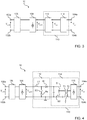
electronic converter 10 is frequently required to be an insulated converter. Consequently, in this case, as shown inFigure 4 , the DC/DC conversion circuit 114 may comprise at least one transformer T, which includes a primary winding T1 and a secondary winding T2. - The DC/
DC conversion circuit 114 comprises one or more electronic switches (for example, S1 and S2) configured to connect the terminals of the primary winding T1 of the transformer T selectively to the rectified voltage Vin,DC supplied by the rectifier circuit 108 (or to the bus voltage Vbus supplied by the filter and/or PFC circuit 112). The electronic switches S1, S2 may be implemented as transistors, for example MOS field-effect transistors (MOSFETs). - The discontinuous (pulsed, AC) voltage at the secondary side T2 of the transformer T is then converted into a DC voltage by means of a
further rectifier circuit 116, typically comprising one or more diodes (for example, a diode bridge). Consequently, the input of therectifier circuit 116 is connected (for example, directly) to the terminals of the secondary winding T2 of the transformer T and supplies at output a DC voltage/current, which in the simplest case corresponds to the output voltage/current Vout /iout . - In a switching converter, the transformer T thus receives at the primary side T1 a discontinuous (pulsed, AC) voltage, which has a switching frequency determined by driving the electronic switches S1 and/or S2. The
electronic converter 10 may hence comprise also a control circuit (not visible inFigure 4 ) configured to generate one or more driving signals for driving the DC/DC conversion circuit 114 and/or thefilter circuit 112, in such a way as to regulate the output voltage Vout or the current output iout on a desired value. For instance, the control circuit may generate respective driving signals for the electronic switches S1 and/or S2. - In general, the control circuit may be any analog circuit and/or a digital circuit, such as a microprocessor programmed via software code.
-
Figure 4 moreover illustrates an example in which theelectronic converter 10 comprises a power factor correction (PFC)circuit 112, in particular a boost topology comprising an inductor L1, a diode D1, an electronic switch S3, and a resistance Rs (optional) arranged in a configuration known per se. - In the field of electronic converters, and in particular electronic converters for the supply of lighting modules (for example, LEDs), energy saving is a desired feature. Energy saving may be obtained, for example, by increasing the efficiency of the
switching stage 110, or by detecting the consumption and regulating the power according to the needs. - In order to detect consumption, the control circuit may be configured to determine some data, such as the input power of the converter. In addition, the control circuit may be configured to transmit, at output from the
electronic converter 10, a signal indicative of the power absorbed at input by the electronic converter. - Different methods for determining the value of the input power in an electronic switching converter are known in the art.
- For example, the input power may be determined indirectly via detection of some electrical quantities in the
switching stage 110 even though this method is usually not accurate. - For instance, as illustrated in
Figure 5 , the control circuit 120 (for example, a microprocessor or microcontroller) of theelectronic converter 10 may be coupled downstream of therectifier circuit 108 for detecting the rectified voltage Vin,DC, and may be coupled (for example, via a filtering network comprising a resistance R and a capacitance C) to the resistor Rs in thePFC circuit 112 for detecting the current that flows therethrough. Measurement of the input power as a function of the rectified voltage Vin,DC and of the current that flows in the resistor Rs may prove reasonable if the load remains constant and the input voltage does not change over time. - Alternatively, as illustrated in
Figure 6 , thecontrol circuit 120 of theelectronic converter 10 may be coupled downstream of the DC/DC conversion circuit 114 for detecting the output current iout supplied to the load, and may be configured to detect the output voltage Vout at a secondary winding L0 of the transformer T. In this way, the input power may be calculated as a function of the value of the power supplied at output by the DC/DC conversion circuit 114. This method is rather common in so far as the output current is usually well known and the output voltage can be measured easily via a secondary winding of the transformer T, or also transferred directly from the secondary side if there is electrical communication between the primary side and the secondary side. - The input power of the
electronic converter 10 may hence be determined as a function of the output power and of the efficiency of theelectronic converter 10. On the other hand, the efficiency of the electronic converter may vary as a function of the variations of the input voltage Vin,AC and of the temperature, in such a way that the value determined of the input power may not be accurate even if the output power is measured in an accurate way. - Yet a further known circuit for determining the input power of the
electronic converter 10 is illustrated inFigure 7 . In this circuit, adedicated microprocessor 700 is configured to detect (directly) the voltage Vin,AC supplied from the supply line to theterminals terminals dedicated microprocessor 700 may be coupled to thecontrol circuit 120 inside theelectronic converter 10 for transmitting thereto a signal (for example, a digital signal) indicative of the input power calculated as a function of the input voltage and of the input current. Thecontrol circuit 120, which controls operation of theelectronic converter 10, can gather other data and send this information at output via acommunication line 122, for example a DALI communication line. - Even though the solution illustrated in
Figure 7 for determining the input power may be more precise than the previous solutions, it is also typically the most expensive in terms of space occupied by the sensing circuit and of cost of the circuit itself. - Yet a further known circuit for determining the input power of an electronic converter is illustrated in
Figure 8 . In this circuit, thecontrol circuit 120 of theelectronic converter 10 is configured to detect the rectified voltage Vin,DC downstream of the rectifier circuit 108 (for example, via a resistive divider comprising the resistances RH, RL). Moreover, theelectronic converter 10 comprises a shunt resistance Rshunt coupled in series between therectifier circuit 108 and theswitching stage 110, and an amplifier circuit 800 (for example, an operational amplifier). Theamplifier circuit 800 has a first input coupled upstream of the resistance Rshunt and a second input coupled downstream of the resistance Rshunt for supplying at output a signal indicative of the current that flows through the resistance Rshunt. This signal is supplied (for example, through a filtering network comprising a resistance RF and a capacitance CF) to thecontrol circuit 120 for calculation of the input power of theelectronic converter 10. - The known solution illustrated in
Figure 8 , which exploits thecontrol circuit 120 without envisaging the use of adedicated microprocessor 700, may provide a sufficient accuracy, while maintaining a cost lower than the solution described with reference toFigure 7 . On the other hand, the shunt resistance Rshunt should have a low resistance value in order not to negatively affect the efficiency of theelectronic converter 10, and this renders necessary use of anamplifier circuit 800 for properly detecting the voltage across theelectronic converter 10. Theamplifier circuit 800 is typically a low-offset amplifier with good temperature stability, and consequently may prove costly. - In the context of the present invention, also the
documents EP 2 608 381 A2 ,US 2015/0028836 A1 ,US 2013/0342122A1 ,WO 2011/076707 A2 , andEP 3 226 409 A1 are representative of various solutions designed to measure electrical quantities in circuits such as may be converter circuits. - However, the inventor has noted that known solutions for determining the input power of an electronic converter may be costly and/or may entail a reduction in efficiency of the converter itself.
- The object of the present disclosure is to provide solutions for determining the input power of an electronic converter (for example, an AC/DC converter as illustrated schematically in
Figure 3 , or a DC/DC converter) that are easy and inexpensive to produce, do not have an adverse impact on the efficiency of the converter itself, and/or are more reliable than known solutions. - According to various embodiments, the above object is achieved by means of an electronic converter having the features set forth in the claims that follow. The claims also relate to a corresponding lighting system and a corresponding method of operating an electronic converter.
- The claims form an integral part of the technical teaching provided herein in relation to the invention.
- Various embodiments of the present disclosure relate to an electronic converter. In various embodiments, the electronic converter comprises two input terminals configured to receive an input voltage (for example, an AC voltage) and two output terminals configured to supply a regulated output voltage or a regulated output current. The electronic converter comprises a switching stage coupled to the two input terminals. The switching stage is configured to receive the input voltage and supply the regulated output voltage or the regulated output current.
- In various embodiments, the electronic converter comprises an input voltage sensing circuit configured to supply a signal proportional to the input voltage, and an input current sensing circuit configured to supply a signal indicative of an input current of the switching stage.
- In various embodiments, the electronic converter comprises a control circuit, which includes an analog-to-digital converter, coupled to the input voltage sensing circuit for detecting one or more sampled values of the signal proportional to the input voltage and coupled to the input current sensing circuit for detecting one or more sampled values of the signal indicative of an input current.
- In various embodiments, the input current sensing circuit comprises a first node coupled to a negative input terminal of the electronic converter, a second node connected to a negative input terminal of the switching stage, and a shunt resistance connected between the first node and the second node in a first current path. The input current sensing circuit further comprises an electronic switch connected between the first node and the second node in a second current path in parallel to said shunt resistance, and a voltage divider comprising a first resistance and a second resistance connected in series between the first node and a supply voltage node.
- In various embodiments, the analog-to-digital converter in the control circuit is configured to measure a voltage between an intermediate node of the aforesaid voltage divider and the second node of the input current sensing circuit, for receiving the signal indicative of an input current.
- In various embodiments, the control circuit is configured to drive the electronic switch, opening the electronic switch in a first time interval and closing the electronic switch in a second time interval, and to determine a value of input power of the electronic converter. The value of input power of the electronic converter is determined as a function of the values of the signal proportional to the input voltage and of the signal indicative of an input current that are sampled during the first time interval, a factor of proportionality between the signal proportional to the input voltage and the input voltage, and values of resistance of the shunt resistance, of the first resistance, and of the second resistance in the input current sensing circuit.
- In various embodiments, the electronic converter comprises a rectifier circuit coupled to the two input terminals and configured to supply a rectified input voltage. The switching stage is coupled to the rectifier circuit and is configured to receive the rectified input voltage. The first node of the input current sensing circuit is connected to a negative output terminal of the rectifier circuit.
- In various embodiments, a value of resistance of the second current path between the first node and the second node of the input current sensing circuit is lower than a value of resistance of the first current path between the first node and the second node, preferably at least five times lower, more preferably at least ten times lower.
- In various embodiments, the input voltage sensing circuit comprises a resistive voltage divider coupled to the two input terminals (for example, via a filter circuit and/or a rectifier circuit) or to the input of the switching stage, and the analog-to-digital converter in the control circuit is connected to an intermediate node of the resistive voltage divider for receiving therefrom the signal proportional to an input voltage.
- In various embodiments, the input voltage sensing circuit is coupled to the two input terminals of the electronic converter and comprises a first voltage divider connected between a first conductor (for example, a live conductor) of an electrical supply line that supplies the input voltage and a reference voltage node, and a second voltage divider coupled between a second conductor (for example, a neutral conductor) of the electrical supply line and the reference voltage node. The analog-to-digital converter in the control circuit is connected to respective intermediate nodes of the first voltage divider and of the second voltage divider for receiving from these the signal proportional to an input voltage as a differential signal between the voltages detected at the respective intermediate nodes.
- In various embodiments, the analog-to-digital converter in the control circuit is coupled to the intermediate node between the first resistance and the second resistance of the input current sensing circuit via a filter circuit configured to filter the electronic noise in the signal indicative of an input current.
- In various embodiments, the input current sensing circuit comprises a Zener diode connected in parallel to the shunt resistance.
- In various embodiments, the input current sensing circuit comprises a current-limiting resistance connected in series to the electronic switch. The value of the current-limiting resistance is lower than the value of the shunt resistance, preferably at least five times lower, more preferably at least ten times lower.
- In various embodiments, the electronic switch comprises a field-effect transistor, preferably of a MOS type, and the electronic converter comprises a decoupling circuit connected between the control circuit and a control terminal (for example, a gate terminal) of the field-effect transistor. The decoupling circuit is configured to transfer a drive signal from the control circuit to the field-effect transistor.
- In various embodiments, the first time interval during which the electronic switch is open has a duration of between 10 ms and 1 s, preferably between 10 ms and 200 ms, more preferably between 100 ms and 200 ms. The second time interval during which the electronic switch is closed has a duration of between 1 s and 5 s, preferably between 2 s and 3 s.
- In various embodiments, the control circuit is configured to determine a value of input power of the electronic converter as a function of a plurality of values of the signal proportional to an input voltage and of the signal indicative of an input current that are sampled during the first time interval. The sampling interval of these signals is preferably between 100 µs and 400 µs.
- In various embodiments, a lighting system comprises a lighting module and an electronic converter according to one or more embodiments.
- Embodiments will now be described, purely by way of non-limiting example, with reference to the annexed drawings, wherein:
-
Figure 1 shows a lighting system; -
Figure 2 shows a lighting module; -
Figure 3 shows a block diagram of an electronic converter; -
Figure 4 shows some implementation details of an insulated electronic converter; -
Figures 5 to 8 show various circuits configured to determine the input power of an electronic converter; -
Figure 9 shows a block diagram of one or more embodiments of an electronic converter; -
Figures 10 to 13 show some implementation details of one or more embodiments of an electronic converter; -
Figures 14A, 14B, and 14C show various waveforms in one or more embodiments of an electronic converter; and -
Figure 15 shows a block diagram of one or more embodiments of an electronic converter. - In the ensuing description, various specific details are illustrated aimed at enabling an in-depth understanding of the embodiments. The embodiments may be provided without one or more of the specific details, or with other methods, components, materials, etc. In other cases, known structures, materials, or operations are not illustrated or described in detail so that various aspects of the embodiments will not be obscured.
- Reference to "an embodiment" or "one embodiment" in the framework of this description is intended to indicate that a particular configuration, structure, or characteristic described in relation to the embodiment is comprised in at least one embodiment. Hence, phrases such as "in an embodiment" or "in one embodiment" that may be present in various points of the present description do not necessarily refer to one and the same embodiment. In addition, particular conformations, structures, or characteristics may be combined in an adequate way in one or more embodiments.
- The references used herein are provided merely for convenience and hence do not define the sphere of protection and the scope of the embodiments.
- In the
Figures 9 to 13 that follow, the parts, elements, or components that have already been described with reference toFigures 1 to 8 are designated by the same references used previously in the above figures; the description of the aforesaid elements described previously will not be repeated hereinafter in order not to overburden the present detailed description. - As mentioned previously, the present disclosure provides solutions for determining the input power of an electronic converter, for example an AC/DC converter as illustrated schematically in
Figure 3 . For the general description of such an electronic converter, also within a lighting system, reference may hence be made to the description ofFigures 1 to 4 . -
Figure 9 shows an embodiment of anelectronic converter 10 comprising a filter circuit 106 (optional), arectifier circuit 108, and aswitching stage 110, which supplies a regulated output voltage/current Vout /iout. The switchingstage 110 comprises a DC/DC conversion circuit and, optionally, a filter circuit and/or a PFC circuit (not visible inFigure 9 ), according to the known scheme described with reference toFigures 1 to 4 . - As illustrated in
Figure 9 , one or more embodiments may comprise: - an input voltage sensing circuit VS, configured to detect an input voltage of the
electronic converter 10, such as the AC voltage Vin,AC supplied at theterminals rectifier circuit 108; - an input current sensing circuit CS, configured to detect the current Is at input to the
switching stage 110; and - a
control circuit 120 of the electronic converter 10 (for example, a microprocessor or microcontroller) coupled to the input voltage sensing circuit VS and to the input current sensing circuit CS and configured to receive therefrom signals indicative, respectively, of the value of the input voltage and the value of the input current, and to determine a value of the input power as a function thereof. - For instance, the
control circuit 120 of theelectronic converter 10 comprises an analog-to-digital converter configured to sample the signals indicative, respectively, of the value of the input voltage and of the input current. - In the embodiment here considered, the input voltage sensing circuit VS may comprise a voltage divider (for example, a resistive voltage divider) coupled between the two output conductors of the
rectifier circuit 108. For instance, the voltage divider may comprise an arrangement in series of a first resistance RVA and a second resistance RVB (for example, two resistors) having an intermediate node. This intermediate node may be coupled to thecontrol circuit 120 for supplying thereto a (voltage) signal Vsense indicative of (for example, proportional to) the value of the rectified voltage Vin,DC at the input of the switchingstage 110. - The input voltage sensing circuit VS may be coupled "downstream" of the input current sensing circuit CS, as illustrated in
Figure 9 , or alternatively may be coupled "upstream" of the input current sensing circuit CS, i.e., directly to the output terminals of therectifier circuit 108. - In the embodiment here considered, the input voltage sensing circuit VS is configured to reduce the value of the rectified voltage Vin,DC supplied by the
rectifier circuit 108 to a value suited to being detected by thecontrol circuit 120, which may be implemented with a microcontroller or a microprocessor. For instance, the factor of proportionality between the input voltage and the signal Vsense at the output of the sensing circuit VS may be comprised between 50 and 500, and the signal Vsense at the output of the sensing circuit VS may have an amplitude comprised between 0 V and 5 V. - The
control circuit 120 is configured to control the switching stage 110 (in particular, to control switching thereof in order to supply at output the desired regulated voltage/current value) and optionally for communicating with devices external to theelectronic converter 10, for example via an interface and anexternal communication line 122, such as a DALI line. - The
control circuit 120 is moreover configured to determine a value of the input power of theelectronic converter 10 as a function of the signals indicative of the value of the input voltage Vsense and of the input current Isense , supplied respectively by the circuits VS and CS. The value of power determined by thecontrol circuit 120 can be communicated to one or more external devices, for example via thecommunication line 122. - In one or more embodiments, the
control circuit 120 may be implemented with a microcontroller that presents a modest level of performance in order to reduce its cost. In this case, and in any case in general, it is preferable for the signals generated by the voltage sensing circuit VS and by the current sensing circuit CS that are supplied at the input of thecontrol circuit 120, to have an appropriate amplitude in order to use, when possible, the entire input range (scale) of the analog-to-digital converter inside thecontrol circuit 120. This solution makes it possible to improve the accuracy of measurement of the quantities, voltage and current, and consequently facilitates a more accurate measurement of the input power of theelectronic converter 10. - In one or more embodiments as exemplified in
Figure 9 , the input current sensing circuit CS comprises: - a shunt resistance Rshunt (for example, a resistor) connected (for example, directly) in series between the
rectifier circuit 108 and the switching stage 110 (for example, coupled to the "negative" conductor at the output of therectifier circuit 108, as illustrated inFigure 9 ), where the shunt resistance Rshunt preferably has a node coupled to a reference voltage node GND (e.g., a ground node), preferably the node coupled to the input of the switchingstage 110; - a voltage divider comprising a first resistance RA and a second resistance RB (for example, two resistors) connected in series between a
supply voltage node 900 and the node NA of the shunt resistance Rshunt that is not coupled to the reference voltage node GND, where thesupply voltage node 900 is configured to supply a supply voltage Vsupply (for example, the same supply voltage as that of the control circuit 120), and where the node NB intermediate between the resistances RA and RB is coupled to thecontrol circuit 120 for supplying thereto a (voltage) signal Isense indicative of the value of the input current; and - an electronic switch S4, connected in parallel to the shunt resistance Rshunt and driven by the
control circuit 120 by means of a control signal (for example, a digital signal) EN. - Consequently, in one or more embodiments as exemplified in
Figure 9 , as a result of the switchingstage 110 supplying power to a load (coupled to theterminals control circuit 120 via the voltage divider RA, RB that generates the (voltage) signal Isense. - In particular, the voltage VB at node NB (corresponding to the signal Isense ) can be determined - possibly with minor approximations - via the following equation:


- The voltage VB at the node NB can hence be converted into a digital value ADvalue via an N-bit analog-to-digital converter (for example, with N = 12 bits) comprised in the
control circuit 120, according to the following equation:
- The
control circuit 120 can thus be configured to determine the value of the current IS at the input of the electronic converter as a function of the digital value ADvalue. For instance, the value of the current IS can be determined via the following equation:
- Purely by way of non-limiting example, one or more embodiments may comprise components sized as follows:
- Rshunt = 5.6 Ω
- RB = 1500 Ω
- RA = 1000 Ω
- Vsupply = 3. 3 V
- VADref = Vsupply /2 = 1.65 V
- In various embodiments, the
control circuit 120 is configured to detect the values of the signals Vsense and Isense at regular intervals (for example, periodic, with a period of between 100 µs and 400 µs) and, for each pair of values detected, calculate a value of input power. - In various embodiments, the input power of the
electronic converter 10 may be calculated by averaging in time the calculated values. For instance, thecontrol circuit 120 may be configured to average the values of power calculated over the range of a semi-period of the input voltage Vin,AC (which, in the case of a voltage Vin,AC having a frequency of 50 Hz, corresponds to a time interval of 10 ms), or over a certain number of semi-periods of the input voltage Vin,AC (for example, 5, 10, or 20 consecutive semi-periods, corresponding to 50, 100 or 200 ms, respectively, in the case of a voltage Vin,AC having a frequency of 50 Hz). - The inventor has noted that the shunt resistance Rshunt coupled in series between the
rectifier circuit 108 and theswitching stage 110 can determine power losses that have a negative impact on the efficiency of theelectronic converter 10. - In the purely exemplary case illustrated previously (with Rshunt = 5.6 Ω), considering a voltage drop Vs = 2 V having an effective value of 1.41 V RMS (root mean square), the power dissipated on the shunt resistance is found to be equal to approximately 0.357 mW. Since a circuit converter sized as illustrated previously can be used, for example, for supplying an output power of approximately 40 W, such a power dissipation on the shunt resistance can bring about a loss of efficiency of almost one percentage point.
- The inventor has noted that, since the power at input to the
electronic converter 10 typically varies in a rather slow way, the time interval that elapses between one measurement of this power and the next can be chosen even rather long, for example approximately 2 or 3 s. - In order not to dissipate power on the shunt resistance Rshunt during the time intervals between one measurement of the input power and the next, various embodiments of the
electronic converter 10 comprise an electronic switch S4 coupled in parallel to the shunt resistance Rshunt, as illustrated inFigure 9 , and controlled by thecontrol circuit 120 via a control signal EN. - In one or more embodiments, the electronic switch S4 may comprise a transistor, for example a MOSFET.
- Consequently, in one or more embodiments, the
control circuit 120 may be configured to: - drive opening of the electronic switch S4 at a given instant t0, allowing the current Is to flow through the shunt resistance Rshunt in order to detect the amplitude of the current Is via the signal Isense ;
- sample (for example, periodically, with a period of between 100 µs and 400 µs) respective values of the signals Isense and Vsense during a certain time interval of duration Δt1, with this time interval preferably corresponding to one or more semi-periods of the input voltage Vin,AC (for example, from one to twenty semi-periods, corresponding to a time interval of 10 to 200 ms in the case of a frequency of 50 Hz);
- at a given instant t1 = t0 + Δt1, drive closing of the electronic switch S4;
- calculate, as a function of the values of the signals Isense and Vsense sampled during the time interval Δ t1, a value of input power of the electronic converter, and optionally communicate this value at output from the electronic converter 10 (for example, through a
data communication line 122 such as a DALI line); and - repeat the previous steps, preferably at regular time intervals (for example, periodically, with a period indicatively comprised between 1 and 5 s, preferably between 2 and 3 s).
- In various embodiments, the power dissipated on the shunt resistance Rshunt can hence advantageously be reduced (even by a factor of 10 or higher), the greater the distance in time between two successive measurements of the input power of the converter, in so far as no power is dissipated on the shunt resistance Rshunt while the signals Isense and Vsense are not being sampled.
- In addition, as exemplified in
Figure 10 , one or more embodiments may comprise a filter circuit of an RC type between the node NB and the respective input of thecontrol circuit 120, configured to reduce the electronic noise on the signal Isense . - In particular, as illustrated in
Figure 10 , the electronic converter may comprise a resistance Rf connected between the node NB and the input of the control circuit 120 (i.e., the node designated by NC) and a capacitance Cf connected between the input of thecontrol circuit 120 and the reference voltage node GND. - In addition, as exemplified in
Figure 11 (where the electronic switch S4 is represented with an n-type MOSFET, according to a preferred embodiment), one or more embodiments may comprise: - a Zener diode Dz coupled in parallel to the shunt resistance Rshunt, in particular having the anode connected to the node NA and the cathode connected to the reference node GND; and/or
- a resistance RS4 (for example, a resistor) connected in series to the electronic switch S4, preferably between the electronic switch S4 and the reference node GND.
- The Zener diode Dz has the function of limiting the voltage applied to the shunt resistance Rshunt in the case of overcurrents, for example due to surge or inrush phenomena.
- The resistance RS4 has the function of limiting the current that flows through the electronic switch S4 (in particular when this is implemented with a transistor, for example a MOSFET) when overcurrents occur. The value of the resistance RS4 may be sized so as to be relatively lower than the value of the shunt resistance Rshunt, for example approximately ten times lower (for example, RS4 = 0.56 Ω if Rshunt = 5.6 Ω).
- Alternatively, various embodiments may comprise an input voltage sensing circuit VS different from the one illustrated in
Figures 9 ,10 , and11 . As illustrated inFigure 12 , the input voltage may be detected "upstream" of therectifier circuit 108, for example using a sensing circuit VS that includes: - a first voltage divider, comprising a first resistance RVLA and a second resistance RVLB (for example, two resistors) connected in series between the live conductor L of the electrical supply line and a reference voltage node GND; and
- a second voltage divider, comprising a first resistance RVNA and a second resistance RVNB (for example, two resistors) connected in series between the neutral conductor N of the electrical supply line and a reference voltage node GND.
- In the embodiment here considered, the
control circuit 120 of theelectronic converter 10 may be coupled to a first node NL intermediate with respect to the first voltage divider and a second node NN intermediate with respect to the second voltage divider (for example, by means of respective inputs of the analog-to-digital converter inside the control circuit 120). Thecontrol circuit 120 may be configured to determine a value of the input voltage as a function of the voltage values detected at the intermediate nodes NL and NN (for example, as a function of the difference between the two voltages detected). - The above embodiment enables measurement of the input voltage in a differential way upstream of the
rectifier circuit 108, thus taking into account the voltage drop on the rectifier circuit itself. Consequently, the input power calculated is more accurate, since it comprises the power dissipated in therectifier circuit 108. - In addition or as an alternative, in various embodiments, as exemplified in
Figure 13 , the electronic switch S4 may be driven via a decoupling circuit DN coupled between thecontrol circuit 120 and a control terminal of the switch S4 (for example, a gate terminal in the case where the switch S4 is implemented with a field-effect transistor of a MOS type). - In particular, in the embodiment here considered, the decoupling circuit DN comprises a transistor (for example, a bipolar transistor) B1 having a current path coupled between the
node 900 of the supply voltage Vsupply and the control terminal of the electronic switch S4. The control terminal of the transistor B1 (for example, a base terminal) is coupled to thecontrol circuit 120, for example via a resistance RB1. The transistor B1 receives from the control circuit 120 a signal EN' for activating or deactivating the electronic switch S4 (i.e., rendering it conductive or non-conductive, closed or open). - In addition, a resistance RB2 may be coupled between the control terminal of the transistor B1 and the
node 900 of the supply voltage Vsupply. - In addition, a resistance RB3 may be coupled between the control terminal of the switch S4 and the node NA (for example, between the gate terminal and the source terminal of a MOSFET that implements the switch S4).
- In the embodiment here considered, the logic level of the signal EN' supplied by the
control circuit 120 is reversed with respect to the logic level of the signal EN received at the switch S4. - It will be noted that one or more of the resistances Rshunt, Rs, R, RH, RL, RF, Rf, RS4, RA, RB, RVA, RVB, RVLA, RVLB, RVNA, RVNB, RB1, RB2 and RB3 may be implemented by means of discrete components, such as resistors and/or by means of other resistive components, including non-discrete ones (for example, resistances integrated on silicon).
-
Figures 14A, 14B and 14C exemplify the possible time plots of electrical signals in various embodiments. In particular: -
Figure 14A illustrates the plot of the voltage VB at the node NB, -
Figure 14B illustrates the plot of the voltage VS on the shunt resistance Rshunt; and -
Figure 14C illustrates the plot of the current Is through the shunt resistance Rshunt. - Various embodiments, as described herein, facilitate a measurement of the input power of the electronic converter with an improved accuracy as compared to known solutions. In particular, the accuracy may be better than ±1% in an input power range of from Pin/2 to Pin, where Pin is the maximum input power of the electronic converter.
- Various embodiments as described herein facilitate a measurement of the input power by means of a reliable and low-cost circuit, where the circuit does not comprise any operational amplifier and makes it possible to achieve a satisfactory accuracy, albeit using a low-cost microcontroller to implement the
control circuit 120. - Various embodiments have been described with reference to
Figures 9 to 13 , which illustrate purely by way of example a converter of an AC/DC type. Obviously, the teachings provided herein for calculation of the input power of an electronic converter may equally be applied to converters of a DC/DC type. In this case, the DC/DC converter may not be provided with afilter circuit 106 and/or arectifier circuit 108, and may be configured to receive directly at theinput terminals Figure 15 . - Again, it will be noted that any one of the embodiments described with reference to
Figures 9 to 13 (i.e., embodiments comprising afilter circuit 106 and/or a rectifier circuit 108) may likewise be used for a conversion of a DC/DC type, receiving a DC voltage at theinput terminals Figures 9 to 13 the output nodes of therectifier circuit 108 may be rendered accessible at the outside of the circuit via respective terminals, for receiving a DC input voltage. - Of course, without prejudice to the principle of the invention, the details of construction and the embodiments may vary, even significantly, with respect to what has been illustrated herein purely by way of non-limiting example, without thereby departing from the scope of the invention, as defined by the annexed claims.
LIST OF REFERENCE SIGNS Electronic converter 10 Input terminal 102a, 102b Output terminal 104a, 104b Filter circuit 106, 112 Rectifier circuit 108, 116 Switching stage 110 DC/ DC conversion circuit 114 Control circuit 120 Communication line 122 Lighting module 20 Input terminal 200a, 200b LED or laser diode L' LED string 22 Current regulator 24 Microprocessor 700 Operational amplifier 800 Supply voltage node 900 Transformer T Primary winding T1 Secondary winding T2, L0 Electronic switch S1, S2, S3, S4 Inductor L1 Diode D1 Voltage sensing circuit VS Current sensing circuit CS Shunt resistance Rshunt Resistance Rs, R, RH, RL, RF, Rf, RS4 Resistance RA, RB, RVA, RVB Resistance RVLA, RVLB, RVNA, RVNB Resistance RB1, RB2, RB3 Capacitance C, CF, Cf Zener diode Dz Decoupling circuit DN Transistor B1 Node NA, NB, NC, NL, NN Live conductor L Neutral conductor N AC input voltage Vin,AC Regulated output voltage Vout Regulated output current iout Rectified voltage Vin,DC Bus voltage Vbus Input current Is Supply voltage Vsupply Signal indicative of the input voltage Vsense Signal indicative of the input current Isense Control signal EN, EN' Voltage on the shunt resistance VS
Claims (13)
- An electronic converter (10), comprising:- two input terminals (102a, 102b) configured to receive an input voltage (Vin,AC ; Vin,DC );- two output terminals (104a, 104b) configured to supply a regulated output voltage (Vout ) or a regulated output current (iout );- a switching stage (110; 112, 114) coupled to the two input terminals (102a, 102b), the switching stage (110; 112, 114) being configured to receive said input voltage (Vin,AC ; Vin,DC ) and supply said regulated output voltage (Vout ) or regulated output current (iout );- an input voltage sensing circuit (VS) configured to supply a signal (Vsense ) proportional to said input voltage (Vin,AC ; Vin,DC );- an input current sensing circuit (CS) configured to supply a signal (Isense ) indicative of an input current (Is ) of said switching stage (110; 112, 114); and- a control circuit (120) comprising an analog-to-digital converter coupled to the input voltage sensing circuit (VS) to sense one or more sampled values of said signal (Vsense ) proportional to said input voltage (Vin,AC ; Vin,DC ), and coupled to the input current sensing circuit (CS) to sense one or more sampled values of said signal (Isense ) indicative of an input current (Is ),wherein the input current sensing circuit (CS) comprises:- a first node (NA) coupled (106, 108) to a negative input terminal (102b) of said electronic converter (10);- a second node (NC) connected to a negative input terminal of said switching stage (110; 112, 114);- a shunt resistance (Rshunt) connected between said first node (NA) and said second node (NC) in a first current path;- an electronic switch (S4) connected between said first node (NA) and said second node (NC) in a second current path in parallel to said shunt resistance (Rshunt) ; and- a voltage divider comprising a first resistance (RA) and a second resistance (RB) connected in series between said first node (NA) and a supply voltage (Vsupply ) node (900),wherein the analog-to-digital converter in the control circuit (120) is configured to measure a voltage between a node (NB) intermediate said first resistance (RA) and said second resistance (RB) and the second node (NC) of the input current sensing circuit (CS) to receive said signal (Isense ) indicative of an input current (Is );
wherein the control circuit (120) is configured to:- drive (EN) said electronic switch (S4), opening the electronic switch (S4) in a first time interval and closing the electronic switch (S4) in a second time interval; and- determine a value of input power of the electronic converter (10) as a function of:- said values of said signal (Vsense ) proportional to said input voltage (Vin,AC ; Vin,DC ) and of said signal (Isense ) indicative of an input current (Is ) that are sampled during said first time interval;- a factor of proportionality between said signal (Vsense ) proportional to said input voltage and said input voltage (Vin,DC; Vin,AC ) ; and- values of resistance of the shunt resistance (Rshunt), of the first resistance (RA), and of the second resistance (RB) in the input current sensing circuit (CS). - The electronic converter (10) of claim 1, comprising a rectifier circuit (108) coupled (106) to the two input terminals (102a, 102b) and configured to supply a rectified input voltage (Vin,DC ), wherein:- said switching stage (110; 112, 114) is coupled to the rectifier circuit (108) and is configured to receive said rectified input voltage (Vin,DC ); and- said first node (NA) of the input current sensing circuit (CS) is connected to a negative output terminal of said rectifier circuit (108).
- The electronic converter (10) of claim 1 or claim 2, wherein a resistance value of said second current path between said first node (NA) and said second node (NC) is lower than a resistance value of said first current path between said first node (NA) and said second node (NC), preferably at least five times lower, more preferably at least ten times lower.
- The electronic converter (10) of any of claims 1 to 3, wherein:- the input voltage sensing circuit (VS) comprises a resistive voltage divider (RVA, RVB) coupled to said two input terminals (102a, 102b) or to the input of the switching stage (110; 112, 114); and- the analog-to-digital converter in the control circuit (120) is connected to an intermediate node of said resistive voltage divider (RVA, RVB) to receive therefrom said signal (Vsense ) proportional to said input voltage (Vin,DC ).
- The electronic converter (10) of any of claims 1 to 3, wherein the input voltage sensing circuit (VS) is coupled to said two input terminals (102a, 102b) of the electronic converter (10) and comprises:- a first voltage divider (RVLA, RVLB) connected between a first conductor (L) of an electrical supply line that supplies said input voltage (Vin,AC ) and a reference voltage node (GND); and- a second voltage divider (RVNA, RVNB) connected between a second conductor (N) of said electrical supply line that supplies said input voltage (Vin,AC ) and said reference voltage node (GND),wherein the analog-to-digital converter in the control circuit (120) is connected to respective intermediate nodes (NL, NN) of the first voltage divider (RVLA, RVLB) and of the second voltage divider (RVNA, RVNB) to receive therefrom said signal proportional to an input voltage as differential signal between the voltages detected at said respective intermediate nodes (NL, NN).
- The electronic converter (10) of any of the previous claims, wherein the analog-to-digital converter in the control circuit (120) is coupled to the node intermediate (NB) said first resistance (RA) and said second resistance (RB) via a filter circuit (Rf, Cf) configured to filter the electronic noise in said signal (Isense ) indicative of an input current (Is ).
- The electronic converter (10) of any of the previous claims, wherein the input current sensing circuit (CS) comprises a Zener diode (Dz) connected in parallel to the shunt resistance (Rshunt).
- The electronic converter (10) of any of the previous claims, wherein the input current sensing circuit (CS) comprises a current limiting resistance (RS4) connected in series to said electronic switch (S4), the value of said current limiting resistance (RS4) being lower than the value of the shunt resistance (Rshunt), preferably at least five times lower, more preferably at least ten times lower.
- The electronic converter (10) of any of the previous claims, wherein said electronic switch (S4) comprises a field-effect transistor, preferably a MOS field-effect transistor, and wherein the electronic converter comprises a decoupling circuit (DN) connected between the control circuit (120) and a control terminal of the field-effect transistor, the decoupling circuit (DN) being configured to transfer a drive signal (EN, EN') from the control circuit (120) to the field-effect transistor.
- The electronic converter (10) of any of the previous claims, wherein:- said first time interval during which the electronic switch (S4) is open has a duration of between 10 ms and 1 s, preferably between 10 ms and 200 ms, more preferably between 100 ms and 200 ms; and- said second time interval during which the electronic switch (S4) is closed has a duration of between 1 s and 5 s, preferably between 2 s and 3 s.
- The electronic converter (10) of any of the previous claims, wherein the control circuit (120) is configured to determine a value of input power of the electronic converter (10) as a function of a plurality of values of said signal (Vsense ) proportional to an input voltage and of said signal (Isense ) indicative of an input current (Is ) that are sampled during said first time interval, wherein the sampling interval of said signals is preferably between 100 µs and 400 µs.
- A lighting system comprising a lighting module (20) and an electronic converter (10) according to any of the previous claims.
- A method of operating an electronic converter (10) according to any of claims 1 to 11, comprising:- receiving an input voltage (Vin,AC ; Vin,DC ) at said two input terminals (102a, 102b);- sensing (VS) one or more sampled values of a signal (Vsense ) proportional to said input voltage (Vin,AC ; Vin,DC );- sensing (CS) one or more sampled values of a signal (Isense ) indicative of an input current (Is ) of said switching stage (110; 112, 114);- driving (EN) said electronic switch (S4) in such a way as to open the electronic switch (S4) in a first time interval and close the electronic switch (S4) in a second time interval;- determining a value of input power of the electronic converter (10) as a function of:- values of said signal (Vsense ) proportional to an input voltage and of said signal (Isense ) indicative of an input current (Is ) that are sampled during said first time interval;- a factor of proportionality between said signal (Vsense ) proportional to an input voltage and said input voltage (Vin,DC; Vin,AC ) ; and- values of resistance of the shunt resistance (Rshunt), of the first resistance (RA), and of the second resistance (RB) in the input current sensing circuit (CS).
Applications Claiming Priority (1)
| Application Number | Priority Date | Filing Date | Title |
|---|---|---|---|
| IT201900022158 | 2019-11-26 |
Publications (2)
| Publication Number | Publication Date |
|---|---|
| EP3829043A1 true EP3829043A1 (en) | 2021-06-02 |
| EP3829043A8 EP3829043A8 (en) | 2021-07-28 |
Family
ID=70009100
Family Applications (1)
| Application Number | Title | Priority Date | Filing Date |
|---|---|---|---|
| EP20206854.0A Withdrawn EP3829043A1 (en) | 2019-11-26 | 2020-11-11 | Electronic converter, corresponding lighting system and method of operating an electronic converter |
Country Status (1)
| Country | Link |
|---|---|
| EP (1) | EP3829043A1 (en) |
Cited By (1)
| Publication number | Priority date | Publication date | Assignee | Title |
|---|---|---|---|---|
| CN113409875A (en) * | 2021-06-29 | 2021-09-17 | 上海中航光电子有限公司 | Drive circuit and display device |
Citations (8)
| Publication number | Priority date | Publication date | Assignee | Title |
|---|---|---|---|---|
| WO2003001315A1 (en) * | 2001-06-21 | 2003-01-03 | Champion Microelectronic Corp. | Volt-second balanced pfc-pwm power converter |
| US20060061337A1 (en) * | 2004-09-21 | 2006-03-23 | Jung-Won Kim | Power factor correction circuit |
| WO2011076707A2 (en) | 2009-12-23 | 2011-06-30 | Control Techniques Ltd | Voltage compensation |
| EP2608381A2 (en) | 2011-11-29 | 2013-06-26 | Samsung Electronics Co., Ltd | AC-DC converter |
| US20130342122A1 (en) | 2011-03-07 | 2013-12-26 | Rohm Co., Ltd. | Switching current control circuit, led dimmer system, and led illumination device |
| US20150009715A1 (en) * | 2012-01-25 | 2015-01-08 | Soongsil University Research Consortium Techno-Park | Power saving current measuring apparatus and power converter using same |
| US20150028836A1 (en) | 2013-07-29 | 2015-01-29 | Infineon Technologies Ag | System and Method for a Converter Circuit |
| EP3226409A1 (en) | 2016-03-28 | 2017-10-04 | Mitsubishi Heavy Industries, Ltd. | Power converting device and air conditioner |
-
2020
- 2020-11-11 EP EP20206854.0A patent/EP3829043A1/en not_active Withdrawn
Patent Citations (8)
| Publication number | Priority date | Publication date | Assignee | Title |
|---|---|---|---|---|
| WO2003001315A1 (en) * | 2001-06-21 | 2003-01-03 | Champion Microelectronic Corp. | Volt-second balanced pfc-pwm power converter |
| US20060061337A1 (en) * | 2004-09-21 | 2006-03-23 | Jung-Won Kim | Power factor correction circuit |
| WO2011076707A2 (en) | 2009-12-23 | 2011-06-30 | Control Techniques Ltd | Voltage compensation |
| US20130342122A1 (en) | 2011-03-07 | 2013-12-26 | Rohm Co., Ltd. | Switching current control circuit, led dimmer system, and led illumination device |
| EP2608381A2 (en) | 2011-11-29 | 2013-06-26 | Samsung Electronics Co., Ltd | AC-DC converter |
| US20150009715A1 (en) * | 2012-01-25 | 2015-01-08 | Soongsil University Research Consortium Techno-Park | Power saving current measuring apparatus and power converter using same |
| US20150028836A1 (en) | 2013-07-29 | 2015-01-29 | Infineon Technologies Ag | System and Method for a Converter Circuit |
| EP3226409A1 (en) | 2016-03-28 | 2017-10-04 | Mitsubishi Heavy Industries, Ltd. | Power converting device and air conditioner |
Cited By (1)
| Publication number | Priority date | Publication date | Assignee | Title |
|---|---|---|---|---|
| CN113409875A (en) * | 2021-06-29 | 2021-09-17 | 上海中航光电子有限公司 | Drive circuit and display device |
Also Published As
| Publication number | Publication date |
|---|---|
| EP3829043A8 (en) | 2021-07-28 |
Similar Documents
| Publication | Publication Date | Title |
|---|---|---|
| CN104980021B (en) | System and method for switched-mode power supply | |
| US7781985B2 (en) | Constant current driver circuit with voltage compensated current sense mirror | |
| US8154214B2 (en) | Switching power supply for an illumination device with precision current control | |
| US9974129B1 (en) | Circuit and method for LED current regulation and ripple control | |
| US10186983B2 (en) | Ideal diode bridge rectifying circuit and control method | |
| US10436620B2 (en) | Excitation circuit for electromagnetic flow meter, and electromagnetic flow meter | |
| US9693417B2 (en) | LED mains voltage measurement using a current mirror | |
| TWI583120B (en) | A system and method for providing an output current to one or more light emitting diodes | |
| US20230275507A1 (en) | Control Circuit of Power Factor Improvement Circuit and Semiconductor Integrated Circuit Device | |
| EP3829043A1 (en) | Electronic converter, corresponding lighting system and method of operating an electronic converter | |
| WO2012155325A1 (en) | Dc/dc power converter with wide input voltage range | |
| US10461632B1 (en) | Current sensing for bridgeless PFC converters | |
| KR20130135757A (en) | Apparatus for controlling led string | |
| CN110176853A (en) | Current sense device and associated method | |
| US7122984B2 (en) | Method for identifying an overload current of an electric drive | |
| CN107396495B (en) | Constant-current driving device and lamp | |
| CN206181440U (en) | Voltage sampling circuit | |
| KR20200018446A (en) | Advanced Gate Drivers for Silicon Carbide Bipolar Junction Transistors | |
| EP1836762B1 (en) | Enhancing the efficiency of ac-dc low voltage power supplies by topological modifications | |
| CN107087328B (en) | LED driving circuit | |
| EP3393042A1 (en) | Electronic apparatus having a serial and digital transmission output and device for measuring electric quantities comprising said electronic apparatus | |
| KR101711343B1 (en) | Output current sensing method for single-phase grid-connected photovolataic inverters | |
| CN203645895U (en) | Load sampling circuit of non-isolated LED driving circuit | |
| CN219395087U (en) | State detection circuit, dimming and toning control circuit and dimming system | |
| CN103763819B (en) | The load sample circuit of non-isolated LED driving circuit |
Legal Events
| Date | Code | Title | Description |
|---|---|---|---|
| PUAI | Public reference made under article 153(3) epc to a published international application that has entered the european phase |
Free format text: ORIGINAL CODE: 0009012 |
|
| STAA | Information on the status of an ep patent application or granted ep patent |
Free format text: STATUS: THE APPLICATION HAS BEEN PUBLISHED |
|
| AK | Designated contracting states |
Kind code of ref document: A1 Designated state(s): AL AT BE BG CH CY CZ DE DK EE ES FI FR GB GR HR HU IE IS IT LI LT LU LV MC MK MT NL NO PL PT RO RS SE SI SK SM TR |
|
| RAP3 | Party data changed (applicant data changed or rights of an application transferred) |
Owner name: OSRAM GMBH Owner name: OSRAM S.P.A. - SOCIETA' RIUNITE OSRAM EDISON CLERICI |
|
| STAA | Information on the status of an ep patent application or granted ep patent |
Free format text: STATUS: REQUEST FOR EXAMINATION WAS MADE |
|
| 17P | Request for examination filed |
Effective date: 20211201 |
|
| RBV | Designated contracting states (corrected) |
Designated state(s): AL AT BE BG CH CY CZ DE DK EE ES FI FR GB GR HR HU IE IS IT LI LT LU LV MC MK MT NL NO PL PT RO RS SE SI SK SM TR |
|
| STAA | Information on the status of an ep patent application or granted ep patent |
Free format text: STATUS: EXAMINATION IS IN PROGRESS |
|
| 17Q | First examination report despatched |
Effective date: 20220527 |
|
| STAA | Information on the status of an ep patent application or granted ep patent |
Free format text: STATUS: THE APPLICATION HAS BEEN WITHDRAWN |
|
| 18W | Application withdrawn |
Effective date: 20220930 |