EP3736940B1 - System and method for coordinated control of reactive power from a generator and a reactive power compensation device in a wind turbine system - Google Patents
System and method for coordinated control of reactive power from a generator and a reactive power compensation device in a wind turbine system Download PDFInfo
- Publication number
- EP3736940B1 EP3736940B1 EP20173047.0A EP20173047A EP3736940B1 EP 3736940 B1 EP3736940 B1 EP 3736940B1 EP 20173047 A EP20173047 A EP 20173047A EP 3736940 B1 EP3736940 B1 EP 3736940B1
- Authority
- EP
- European Patent Office
- Prior art keywords
- reactive power
- qmvb
- wind turbine
- power
- qcmd
- Prior art date
- Legal status (The legal status is an assumption and is not a legal conclusion. Google has not performed a legal analysis and makes no representation as to the accuracy of the status listed.)
- Active
Links
- 238000000034 method Methods 0.000 title claims description 37
- 238000010248 power generation Methods 0.000 claims description 20
- 230000003068 static effect Effects 0.000 claims description 9
- 230000006698 induction Effects 0.000 claims description 7
- 230000001360 synchronised effect Effects 0.000 claims description 5
- 230000007812 deficiency Effects 0.000 claims 5
- 238000010586 diagram Methods 0.000 description 11
- 239000003990 capacitor Substances 0.000 description 3
- 230000001276 controlling effect Effects 0.000 description 3
- 230000006735 deficit Effects 0.000 description 3
- 230000008569 process Effects 0.000 description 3
- 238000006243 chemical reaction Methods 0.000 description 2
- 230000006870 function Effects 0.000 description 2
- 230000008676 import Effects 0.000 description 2
- 230000010354 integration Effects 0.000 description 2
- 230000000116 mitigating effect Effects 0.000 description 2
- 238000012986 modification Methods 0.000 description 2
- 230000004048 modification Effects 0.000 description 2
- 230000005540 biological transmission Effects 0.000 description 1
- 230000003247 decreasing effect Effects 0.000 description 1
- 230000009977 dual effect Effects 0.000 description 1
- 230000001105 regulatory effect Effects 0.000 description 1
- 230000001052 transient effect Effects 0.000 description 1
- 238000004804 winding Methods 0.000 description 1
Images


Classifications
-
- H—ELECTRICITY
- H02—GENERATION; CONVERSION OR DISTRIBUTION OF ELECTRIC POWER
- H02J—CIRCUIT ARRANGEMENTS OR SYSTEMS FOR SUPPLYING OR DISTRIBUTING ELECTRIC POWER; SYSTEMS FOR STORING ELECTRIC ENERGY
- H02J3/00—Circuit arrangements for ac mains or ac distribution networks
- H02J3/38—Arrangements for parallely feeding a single network by two or more generators, converters or transformers
- H02J3/46—Controlling of the sharing of output between the generators, converters, or transformers
- H02J3/50—Controlling the sharing of the out-of-phase component
-
- F—MECHANICAL ENGINEERING; LIGHTING; HEATING; WEAPONS; BLASTING
- F03—MACHINES OR ENGINES FOR LIQUIDS; WIND, SPRING, OR WEIGHT MOTORS; PRODUCING MECHANICAL POWER OR A REACTIVE PROPULSIVE THRUST, NOT OTHERWISE PROVIDED FOR
- F03D—WIND MOTORS
- F03D7/00—Controlling wind motors
- F03D7/02—Controlling wind motors the wind motors having rotation axis substantially parallel to the air flow entering the rotor
- F03D7/0272—Controlling wind motors the wind motors having rotation axis substantially parallel to the air flow entering the rotor by measures acting on the electrical generator
-
- F—MECHANICAL ENGINEERING; LIGHTING; HEATING; WEAPONS; BLASTING
- F03—MACHINES OR ENGINES FOR LIQUIDS; WIND, SPRING, OR WEIGHT MOTORS; PRODUCING MECHANICAL POWER OR A REACTIVE PROPULSIVE THRUST, NOT OTHERWISE PROVIDED FOR
- F03D—WIND MOTORS
- F03D7/00—Controlling wind motors
- F03D7/02—Controlling wind motors the wind motors having rotation axis substantially parallel to the air flow entering the rotor
- F03D7/04—Automatic control; Regulation
- F03D7/042—Automatic control; Regulation by means of an electrical or electronic controller
- F03D7/047—Automatic control; Regulation by means of an electrical or electronic controller characterised by the controller architecture, e.g. multiple processors or data communications
-
- F—MECHANICAL ENGINEERING; LIGHTING; HEATING; WEAPONS; BLASTING
- F03—MACHINES OR ENGINES FOR LIQUIDS; WIND, SPRING, OR WEIGHT MOTORS; PRODUCING MECHANICAL POWER OR A REACTIVE PROPULSIVE THRUST, NOT OTHERWISE PROVIDED FOR
- F03D—WIND MOTORS
- F03D7/00—Controlling wind motors
- F03D7/02—Controlling wind motors the wind motors having rotation axis substantially parallel to the air flow entering the rotor
- F03D7/04—Automatic control; Regulation
- F03D7/042—Automatic control; Regulation by means of an electrical or electronic controller
- F03D7/048—Automatic control; Regulation by means of an electrical or electronic controller controlling wind farms
-
- H—ELECTRICITY
- H02—GENERATION; CONVERSION OR DISTRIBUTION OF ELECTRIC POWER
- H02J—CIRCUIT ARRANGEMENTS OR SYSTEMS FOR SUPPLYING OR DISTRIBUTING ELECTRIC POWER; SYSTEMS FOR STORING ELECTRIC ENERGY
- H02J3/00—Circuit arrangements for ac mains or ac distribution networks
- H02J3/18—Arrangements for adjusting, eliminating or compensating reactive power in networks
- H02J3/1885—Arrangements for adjusting, eliminating or compensating reactive power in networks using rotating means, e.g. synchronous generators
-
- H—ELECTRICITY
- H02—GENERATION; CONVERSION OR DISTRIBUTION OF ELECTRIC POWER
- H02M—APPARATUS FOR CONVERSION BETWEEN AC AND AC, BETWEEN AC AND DC, OR BETWEEN DC AND DC, AND FOR USE WITH MAINS OR SIMILAR POWER SUPPLY SYSTEMS; CONVERSION OF DC OR AC INPUT POWER INTO SURGE OUTPUT POWER; CONTROL OR REGULATION THEREOF
- H02M1/00—Details of apparatus for conversion
- H02M1/02—Circuits specially adapted for the generation of grid-control or igniter-control voltages for discharge tubes incorporated in static converters
-
- H—ELECTRICITY
- H02—GENERATION; CONVERSION OR DISTRIBUTION OF ELECTRIC POWER
- H02J—CIRCUIT ARRANGEMENTS OR SYSTEMS FOR SUPPLYING OR DISTRIBUTING ELECTRIC POWER; SYSTEMS FOR STORING ELECTRIC ENERGY
- H02J2300/00—Systems for supplying or distributing electric power characterised by decentralized, dispersed, or local generation
- H02J2300/20—The dispersed energy generation being of renewable origin
- H02J2300/28—The renewable source being wind energy
-
- Y—GENERAL TAGGING OF NEW TECHNOLOGICAL DEVELOPMENTS; GENERAL TAGGING OF CROSS-SECTIONAL TECHNOLOGIES SPANNING OVER SEVERAL SECTIONS OF THE IPC; TECHNICAL SUBJECTS COVERED BY FORMER USPC CROSS-REFERENCE ART COLLECTIONS [XRACs] AND DIGESTS
- Y02—TECHNOLOGIES OR APPLICATIONS FOR MITIGATION OR ADAPTATION AGAINST CLIMATE CHANGE
- Y02E—REDUCTION OF GREENHOUSE GAS [GHG] EMISSIONS, RELATED TO ENERGY GENERATION, TRANSMISSION OR DISTRIBUTION
- Y02E10/00—Energy generation through renewable energy sources
- Y02E10/70—Wind energy
- Y02E10/72—Wind turbines with rotation axis in wind direction
-
- Y—GENERAL TAGGING OF NEW TECHNOLOGICAL DEVELOPMENTS; GENERAL TAGGING OF CROSS-SECTIONAL TECHNOLOGIES SPANNING OVER SEVERAL SECTIONS OF THE IPC; TECHNICAL SUBJECTS COVERED BY FORMER USPC CROSS-REFERENCE ART COLLECTIONS [XRACs] AND DIGESTS
- Y02—TECHNOLOGIES OR APPLICATIONS FOR MITIGATION OR ADAPTATION AGAINST CLIMATE CHANGE
- Y02E—REDUCTION OF GREENHOUSE GAS [GHG] EMISSIONS, RELATED TO ENERGY GENERATION, TRANSMISSION OR DISTRIBUTION
- Y02E10/00—Energy generation through renewable energy sources
- Y02E10/70—Wind energy
- Y02E10/76—Power conversion electric or electronic aspects
-
- Y—GENERAL TAGGING OF NEW TECHNOLOGICAL DEVELOPMENTS; GENERAL TAGGING OF CROSS-SECTIONAL TECHNOLOGIES SPANNING OVER SEVERAL SECTIONS OF THE IPC; TECHNICAL SUBJECTS COVERED BY FORMER USPC CROSS-REFERENCE ART COLLECTIONS [XRACs] AND DIGESTS
- Y02—TECHNOLOGIES OR APPLICATIONS FOR MITIGATION OR ADAPTATION AGAINST CLIMATE CHANGE
- Y02E—REDUCTION OF GREENHOUSE GAS [GHG] EMISSIONS, RELATED TO ENERGY GENERATION, TRANSMISSION OR DISTRIBUTION
- Y02E40/00—Technologies for an efficient electrical power generation, transmission or distribution
- Y02E40/30—Reactive power compensation
Definitions
- the present disclosure relates generally to power generating systems, and, more particularly, to a system and method for coordinated control of various sources of reactive power in a wind turbine system.
- the generator is electrically coupled to a bi-directional power converter that includes a rotor-side converter (RSC) joined to a line-side converter (LSC) via a regulated DC link.
- RSC rotor-side converter
- LSC line-side converter
- Each of the RSC and the LSC typically includes a bank of pulse width modulated switching devices, for example insulated gate bipolar transistors (IGBT modules).
- IGBT modules insulated gate bipolar transistors
- the LSC converts the DC power on the DC link into AC output power that is combined with the power from the generator stator to provide multi-phase power having a frequency maintained substantially at the frequency of the electrical grid bus (e.g. 50 HZ or 60 HZ).
- the above system is generally referred to as a doubly-fed induction generator (DFIG) system, whose operating principles include that the rotor windings are connected to the grid via slip rings and the power converter controls rotor current and voltage. Control of rotor voltage and current enables the generator to remain synchronized with the grid frequency while the wind turbine speed varies (e.g., rotor frequency can differ from the grid frequency). Also, the primary source of reactive power from the DFIG system is from the RSC via the generator (generator stator-side reactive power) and the LSC (generator line-side reactive power).
- DFIG doubly-fed induction generator
- the power converter in particular the RSC
- the generator is able to import or export reactive power, which allows the system to support the grid during extreme voltage fluctuations on the grid.
- the amount of reactive power to be supplied by a wind farm to the grid during steady-state and transient conditions is established by a code requirement dictated by the grid operator, wherein a wind farm controller determines the reactive power demand made on each wind turbine within the wind farm.
- a local controller at each wind turbine receives and allocates the reactive power demand between the generator sources (e.g., between generator-side reactive power and line-side reactive power).
- CN 103368187 A scribes a method based on improved coordinated control of reactive power in a wind turbine, using a DC chopper and a series dynamic braking resistor SDBR instead of a rotor fast protection crowbar.
- the method is able to control the DC bus voltage and suppress the rotor side overcurrent during a fault, playing the role of protecting the DC side capacitor and the rotor side converter during a fault.
- the stator side of the generator can provide reactive power support to the grid during a fault.
- a reactive power compensation device STATCOM is installed at the grid point. The reactive power coordination control method between the doubly-fed turbine and the STATCOM is given considering the principle of minimum utilization of reactive power devices.
- the present disclosure is directed to a method for operating a power generation system according to claim 1.
- the coordination step may include, when (Qcmd) is less than the maximum capacity of (Qmvb), supplying all of (Qcmd) with (Qmvb).
- the maximum reactive power capacities for (Qmvb), (Qs), and (Ql) are determined in real-time based on any one or combination of: power system operating state; ambient temperature; or thermal constraints of the generator; power converter, or reactive power compensation device.
- the values for (Qmvb), (Qs), and (Ql) may be continuously or periodically determined and updated in the control system.
- the method encompasses controlling a wind turbine with a doubly fed induction generator (DFIG) system, wherein (Qcmd) is a reactive power demand made on the wind turbine.
- the wind turbine may be one of a plurality of wind turbines within a wind farm that supplies real and reactive power to the grid, and wherein (Qcmd) is determined by a farm-level controller within the wind farm and transmitted to a local controller at the wind turbine.
- the wind turbine local controller may then allocate (Qmvb) to the reactive power compensation device, and (Qs), and (Ql) to the power converter.
- the wind turbine local controller transmits (Qcmd) to a converter controller associated with the power converter, wherein the converter controller allocates (Qmvb) to the reactive power compensation device and controls operation of the power converter to generate (Qs), and (Ql) to supply (Qcmd).
- the present subject matter also encompasses a power generating system that utilizes the method discussed above.
- the invention encompasses a wind turbine system configured to supply real and reactive power to a grid, the wind turbine system including a wind turbine with a rotor, hub, and a plurality of blades coupled to the hub.
- a doubly fed induction generator (DFIG) system is coupled to the rotor, the DFIG system further comprising a power converter with a line side converter (LSC) and a rotor side converter (RSC), wherein the DFIG system is configured to generate a generator stator-side reactive power (Qs) and a generator line-side reactive power (Ql).
- LSC line side converter
- RSC rotor side converter
- the wind turbine system further includes a dedicated reactive power compensation device operationally configured with the DFIG system to generate a reactive power (Qmvb).
- a local control system is configured to allocate (Qs), (Ql), and (Qmvb) according to the method discussed above to supply the reactive power demand (Qcmd) made on the DFIG.
- the reactive power compensation device may be any one or combination of a Static VAR compensator (SVC), a Static VAR Generator (SVG) device, or a Static Synchronous Compensator (STATCOM) device.
- SVC Static VAR compensator
- SVG Static VAR Generator
- STATCOM Static Synchronous Compensator
- the present subject matter is directed to a system and method for operating a power generation system that supplies real and reactive power to a grid, as discussed above, wherein the power generation system includes a generator with a power converter and a dedicated, individual integrated reactive power compensation device.
- the power generation system may be configured as a wind turbine with a DFIG system, wherein the wind turbine may be one of a plurality of wind turbines in a wind farm.
- the method includes receiving a total reactive power demand (Qcmd) made on the power generation system at a real-time operating state of the power generation system and grid state.
- a maximum reactive power capacity is determined for each of a generator stator-side reactive power (Qs), a generator line-side reactive power (Ql), and reactive power from the reactive power compensation device (Qmvb).
- Supply of (Qcmd) allocated between (Qs), (Ql), and (Qmvb) is coordinated at the real-time operating state of the power generation system and the grid state, wherein (Qmvb) is prioritized as a first source of reactive power, and one or both of (Qs) and (Ql) as a second source of reactive power.
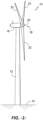
- FIG. 1 illustrates a perspective view of one embodiment of a wind turbine 10.
- the wind turbine 10 generally includes a tower 12 extending from a support surface 14, a nacelle 16 mounted on the tower 12, and a rotor 18 coupled to the nacelle 16.
- the rotor 18 includes a rotatable hub 20 and at least one rotor blade 22 coupled to and extending outwardly from the hub 20.
- the rotor 18 includes three rotor blades 22.
- the rotor 18 may include more or less than three rotor blades 22.
- Each rotor blade 22 may be spaced about the hub 20 to facilitate rotating the rotor 18 to enable kinetic energy to be transferred from the wind into usable mechanical energy, and subsequently, electrical energy.
- the rotor 18 may be rotatably coupled to an electric generator 120 ( FIG. 2 ) for production of electrical energy.
- Wind power generation is typically provided by a wind farm having a large number (often 100 or more) of the wind turbines 10 with associated wind turbine generators 120 ( FIG. 2 ), wherein each individual wind turbine 10 typically experiences a unique wind force. Accordingly, the output power for each individual wind turbine generator 120 may vary from one wind turbine 10 to another wind turbine 10 within the wind farm.
- active power (P) and reactive power (Q) are provided by each wind turbine generator system (e.g., the system 100 depicted in FIG. 2 ).
- a farm-level controller 177 FIG. 5 ) provides reactive power commands (Qcmd) to the wind turbine generator system based on transmission grid needs (which may be dictated by the grid operator or determined based on grid voltage).
- the (Qcmd) demand may be identical for each wind turbine generator.
- the reactive power commands may be individually tailored to the wind turbine generators 120 in the wind farm based on the different power generation characteristics of the respective wind turbine generators 120, as described, for example in US Pat. Pub. No. 2015/0295529 . It should be appreciated that the present invention is not limited to the manner or methodology in which the reactive power command for an individual wind turbine generator 120 is generated.
- FIG. 2 a schematic diagram is provided of a wind turbine generator system embodied as a wind turbine DFIG power system 100 ("wind turbine system") in accordance with aspects of the present subject matter.
- wind turbine system a wind turbine DFIG power system 100
- the rotor 18 of the wind turbine 10 may, optionally, be coupled to a gear box 118, which is, in turn, coupled to the generator 120, which may be a doubly fed induction generator (DFIG).
- DFIG doubly fed induction generator
- the DFIG 120 is connected to a stator bus 154.
- a power converter is connected to the DFIG 120 via a rotor bus 156, and to the stator bus 154 via a line side bus 188.
- the stator bus 154 provides an output multiphase power (e.g. three-phase power) from a stator of the DFIG 120
- the rotor bus 156 provides an output multiphase power (e.g. three-phase power) from a rotor of the DFIG 120.
- the power converter 162 includes a rotor side converter (RSC) 166 and a line side converter (LSC) 168.
- the DFIG 120 is coupled via the rotor bus 156 to the rotor side converter 166.
- the RSC 166 is coupled to the LSC 168 via a DC link 136 across which is a DC link capacitor 138.
- the LSC 168 is, in turn, coupled to a line side bus 188.
- the RSC 166 and the LSC 168 may be configured for normal operating mode in a three-phase, pulse width modulation (PWM) arrangement using insulated gate bipolar transistor (IGBT) switching elements, as will be discussed in more detail with respect to FIG. 3 .
- PWM pulse width modulation
- IGBT insulated gate bipolar transistor
- the power converter 162 is coupled to a converter controller 174 in order to control the operation of the rotor side converter 166 and the line side converter 168.
- the converter controller 174 may be configured as an interface between the power converter 162 and a local wind turbine controller (control system) 176 and include any number of control devices.
- the controller 174 may include a processing device (e.g. microprocessor, microcontroller, etc.) executing computer-readable instructions stored in a computer-readable medium. The instructions when executed by the processing device may cause the processing device to perform operations, including providing control commands (e.g. switching frequency commands) to the switching elements of the power converter 162.
- control commands e.g. switching frequency commands
- the reactive power is supplied primarily by the RSC, via the generator 120 and the LSC.
- various line contactors and circuit breakers including, for example, a grid breaker 182 may also be included for isolating the various components as necessary for normal operation of the DFIG 120 during connection to and disconnection from a load, such as the electrical grid 184.
- a system circuit breaker 178 may couple the system bus 160 to a transformer 180, which may be coupled to the electrical grid 184 via the grid breaker 182.
- fuses may replace some or all of the circuit breakers.
- alternating current power generated at the DFIG 120 by rotating the rotor 18 is provided to the electrical grid 184 via dual paths defined by the stator bus 154 and the rotor bus 156.
- sinusoidal multi-phase (e.g. three-phase) alternating current (AC) power is provided to the power converter 162.
- the rotor side power converter 166 converts the AC power provided from the rotor bus 156 into direct current (DC) power and provides the DC power to the DC link 136.
- switching elements e.g. IGBTs
- IGBTs switching elements used in the bridge circuits of the rotor side power converter 166 may be modulated to convert the AC power provided from the rotor bus 156 into DC power suitable for the DC link 136.
- the line side converter 168 converts the DC power on the DC link 136 into AC output power suitable for the electrical grid 184.
- switching elements e.g. IGBTs
- the AC power from the power converter 162 can be combined with the power from the stator of DFIG 120 to provide multi-phase power (e.g. three-phase power) having a frequency maintained substantially at the frequency of the electrical grid 184 (e.g. 50 Hz or 60 Hz).
- various circuit breakers and switches such as grid breaker 182, system breaker 178, stator sync switch 158, converter breaker 186, and line contactor 172 may be included in the wind turbine power system 100 to connect or disconnect corresponding buses, for example, when current flow is excessive and may damage components of the wind turbine power system 100 or for other operational considerations. Additional protection components may also be included in the wind turbine power system 100.
- the power converter 162 may receive control signals from, for instance, the local control system 176 via the converter controller 174.
- the control signals may be based, among other things, on sensed conditions or operating characteristics of the wind turbine power system 100, and provide for control of the operation of the power converter 162.
- feedback in the form of a sensed speed of the DFIG 120 may be used to control the conversion of the output power from the rotor bus 156 to maintain a proper and balanced multi-phase (e.g. three-phase) power supply.
- the sensed speed may be used as a basis for adjusting the switching frequency of the switching elements (e.g., when the DIFG 120 is operating at or near its synchronous speed).
- controller 174 or control system 176 may also be used by the controller 174 or control system 176 to control the power converter 162, including, for example, stator and rotor bus voltages and current feedbacks.
- switching control signals e.g. gate timing commands for IGBTs
- stator synchronizing control signals e.g. stator synchronizing control signals
- circuit breaker signals may be generated.
- the power converter 162 also compensates or adjusts the frequency of the three-phase power from the rotor for changes, for example, in the wind speed at hub 20 and blades 22. Therefore, mechanical and electrical rotor frequencies are decoupled and the electrical stator and rotor frequency matching is facilitated substantially independently of the mechanical rotor speed.
- the bi-directional characteristics of the power converter 162, and specifically, the bi-directional characteristics of the LSC 168 and RSC 166 facilitate feeding back at least some of the generated electrical power into generator rotor. More specifically, electrical power is transmitted from the stator bus 154 to line side bus 188 and subsequently through the line contactor 172 and into the power converter 162, specifically the LSC 168 which acts as a rectifier and rectifies the sinusoidal, three-phase AC power to DC power. The DC power is transmitted into DC link 136. Capacitor 138 facilitates mitigating DC link voltage amplitude variations by facilitating mitigation of a DC ripple sometimes associated with three-phase AC rectification.
- the DC power is subsequently transmitted to the RSC 166 that converts the DC electrical power to a three-phase, sinusoidal AC electrical power with predetermined voltages, currents, and frequencies. This conversion is monitored and controlled via converter controller 174.
- the converted AC power is transmitted from RSC 166 via rotor bus 156 to the generator rotor. In this manner, generator reactive power control is facilitated by controlling rotor current and voltage.
- the rotor side converter (RSC) 166 includes a plurality of bridge circuits (e.g. H-bridge circuits), with each phase of the rotor bus 156 input to the rotor side converter 166 being coupled to a single bridge circuit.
- the line side converter (LSC) 168 may also include a plurality of bridge circuits. Similar to the rotor side converter 166, the line side converter 168 also includes a single bridge circuit for each output phase of the line converter 168.
- the line side converter 168, the rotor side converter 166, or both the line side converter 168 and the rotor side converter 166 may include parallel bridge circuits without deviating from the scope of the present disclosure.
- Each bridge circuit may generally include a plurality of switching elements (e.g. IGBTs) coupled in series with one another.
- each bridge circuit includes an upper IGBT (e.g. IGBT 212) and a lower IGBT (e.g. IGBT 214).
- a diode may be coupled in parallel with each of the IGBTs.
- parallel IGBTs and diodes may be used to increase the current rating of the converter.
- the line side converter 168 and the rotor side converter 166 may be controlled, for instance, by providing control commands, using a suitable driver circuit, to the gates of the IGBTs.
- the converter controller 174 may provide suitable gate timing commands to the gates of the IGBTs of the bridge circuits.
- the control commands may control the switching frequency of the IGBTs to provide a desired output.
- the power convertor 162 may include any other suitable switching elements.
- FIG. 4 depicts real (P) and reactive (Q) power flow in a wind turbine power system 100 configured with a DFIG system 102.
- the primary source of reactive power in the DFIG system is from the RSC 166 via the generator 102 (generator stator-side reactive power (Qs)) and from the RSC 166 via the LSC 168 (generator line-side reactive power (Ql)).
- a harmonic distortion filter 175 is configured in the line side bus.
- Use of the power converter 162, in particular the RSC 166, to control the rotor current makes it is possible to adjust the total reactive power (Qwtg) of the system 100 fed to the grid from the RSC 166 independently of the rotational speed of the generator 102.
- the DFIG generator 102 is able to import or export reactive power, which allows the system to support the grid during extreme voltage fluctuations on the grid.
- the wind turbine power system 100 includes an individual reactive power compensation device 200 (also referred to herein as a modular VAR Box (MVB)) that generates an auxiliary reactive power (Qmvb).
- the reactive power compensation device 200 is connected to the line side bus (with a harmonic distortion filter 175) such that (Qmvb) combines with (QI) on the line side bus as (Q), wherein (Q) and (Qs) are combined at the three-way transformer 202.
- Total reactive power (Qwtg) and total real power (Pwtg) are delivered from the transformer 202 to the grid.
- FIG. 7 is a diagram that depicts various operational locations for integration of the reactive power compensation device 200 locally with an individual wind turbine system 100.
- the dashed line “A” indicates that the reactive power compensation device 200 is connected to the line side bus 188 between the LSC 168 and three-way transformer 202.
- transformer 180 may be a substation transformer at the point of interconnection (POI) with the grid.
- the dashed line “B” indicates that the reactive power compensation device 200 may be connected (via a transformer 204) to a bus 155 downstream of the grid breaker 182 (but in close proximity to the wind turbine system 100) or between the grid breaker 182 and the three-way transformer 202.
- POI point of interconnection
- the present method encompasses controlling a wind turbine 10 with a doubly fed induction generator (DFIG) system 102, wherein the wind turbine 10 may be one of a plurality of wind turbines within a wind farm that supplies real and reactive power to the grid.
- (Qcmd) is a reactive power demand made on the wind turbine by a farm-level controller 177 within the wind farm and transmitted to the local controller 176 at the wind turbine.
- the local controller may then allocate (Qmvb) to the reactive power compensation device 200 (which may include a separate controller) and allocate (Qs), and (Ql) to the converter controller 174 to control the power converter 162 in accordance with the respective reactive power demands.
- FIG. 6 is an alternate embodiment wherein the local wind turbine controller 176 receives the (Qcmd) demand from the field-level controller 177 and transmits the demand to the power converter controller 174.
- the converter controller 174 allocates (Qmvb) to the reactive power compensation device 200 and controls the power converter 162 to generate (Qs) and (Ql).
- a controller may include one or more processor(s) and associated memory device(s) configured to perform a variety of computer-implemented functions.
- processor refers not only to integrated circuits referred to in the art as being included in a computer, but also refers to a controller, a microcontroller, a microcomputer, a programmable logic controller (PLC), an application specific integrated circuit, and other programmable circuits.
- the memory device(s) may generally comprise memory element(s) including, but not limited to, computer readable medium (e.g., random access memory (RAM)), computer readable non-volatile medium (e.g., a flash memory), a floppy disk, a compact disc-read only memory (CD-ROM), a magneto-optical disk (MOD), a digital versatile disc (DVD) and/or other suitable memory elements.
- RAM random access memory
- computer readable non-volatile medium e.g., a flash memory
- CD-ROM compact disc-read only memory
- MOD magneto-optical disk
- DVD digital versatile disc
- Such memory device(s) may generally be configured to store suitable computer-readable instructions that, when implemented by the processor(s), configure the controller to perform various functions, such as the steps disclosed herein.
- FIG. 8 a flow diagram of an embodiment of a method 300 for operating a power generation system is illustrated in accordance with aspects of the present subject matter.
- the method 300 is described herein as implemented using a wind turbine system 100, such as the DFIG wind turbine power system 100 described above.
- the disclosed method 300 may be implemented using any other suitable power generation system that is configured to supply power, including reactive power, for application to a load, such as a power grid.
- FIG. 8 depicts steps performed in a particular order for purposes of illustration and discussion, the methods described herein are not limited to any particular order or arrangement.
- One skilled in the art, using the disclosures provided herein, will appreciate that various steps of the methods can be omitted, rearranged, combined and/or adapted in various ways.
- the method 300 includes receiving a reactive power command (Qcmd) at the wind turbine power system, wherein (Qcmd) may be generated by a farm-level controller in a wind farm.
- the reactive power capacity is determined for each of the reactive power compensation device (Qmvb), the generator stator-side (Qs), and the generator line-side (Ql) at the wind turbine power system.
- the maximum reactive power capacities for (Qmvb), (Qs), and (Ql) are determined in real-time based on any one or combination of: power system operating state; ambient temperature; or thermal constraints of the generator; power converter, or reactive power compensation device.
- the values for (Qmvb), (Qs), and (Ql) may be continuously or periodically determined and updated in the control system.
Landscapes
- Engineering & Computer Science (AREA)
- Power Engineering (AREA)
- Life Sciences & Earth Sciences (AREA)
- Sustainable Development (AREA)
- Sustainable Energy (AREA)
- Chemical & Material Sciences (AREA)
- Combustion & Propulsion (AREA)
- Mechanical Engineering (AREA)
- General Engineering & Computer Science (AREA)
- Control Of Eletrric Generators (AREA)
Description
- The present disclosure relates generally to power generating systems, and, more particularly, to a system and method for coordinated control of various sources of reactive power in a wind turbine system.
- Generally, during operation of a wind turbine, wind impacts the rotor blades and the blades transform wind energy into a mechanical rotational torque that drives a low-speed shaft. The low-speed shaft drives a gearbox that subsequently steps up the low rotational speed of the low-speed shaft to drive a high-speed shaft at an increased rotational speed, wherein the high-speed shaft rotatably drives a generator rotor. In many conventional wind turbine configurations, the generator is electrically coupled to a bi-directional power converter that includes a rotor-side converter (RSC) joined to a line-side converter (LSC) via a regulated DC link. Each of the RSC and the LSC typically includes a bank of pulse width modulated switching devices, for example insulated gate bipolar transistors (IGBT modules). The LSC converts the DC power on the DC link into AC output power that is combined with the power from the generator stator to provide multi-phase power having a frequency maintained substantially at the frequency of the electrical grid bus (e.g. 50 HZ or 60 HZ).
- The above system is generally referred to as a doubly-fed induction generator (DFIG) system, whose operating principles include that the rotor windings are connected to the grid via slip rings and the power converter controls rotor current and voltage. Control of rotor voltage and current enables the generator to remain synchronized with the grid frequency while the wind turbine speed varies (e.g., rotor frequency can differ from the grid frequency). Also, the primary source of reactive power from the DFIG system is from the RSC via the generator (generator stator-side reactive power) and the LSC (generator line-side reactive power). Use of the power converter, in particular the RSC, to control the rotor current/voltage makes it is possible to adjust the reactive power (and real power) fed to the grid from the RSC independently of the rotational speed of the generator. In addition, the generator is able to import or export reactive power, which allows the system to support the grid during extreme voltage fluctuations on the grid.
- Typically, the amount of reactive power to be supplied by a wind farm to the grid during steady-state and transient conditions is established by a code requirement dictated by the grid operator, wherein a wind farm controller determines the reactive power demand made on each wind turbine within the wind farm. A local controller at each wind turbine receives and allocates the reactive power demand between the generator sources (e.g., between generator-side reactive power and line-side reactive power).
- It is known to augment the reactive power capability of a wind farm by use of reactive power compensation devices, such as Static VAR compensator (SVC) or Static VAR Generator (SVG) devices, at one or more common collector buses shared by the wind turbines. For example,
US Patent Application Pub. No. 2017/0025858 describes a wind power plant connected to an electrical grid, the power plant including a plurality of wind turbine generators and a Static Synchronous Compensator (STATCOM) device on a common bus with the wind turbine generators. In a first control mode, the wind turbine generators and STATCOM are operated in master-slave relationship for reactive power generation. Upon a trigger signal, such as a low voltage event on the grid, a second control mode is implemented wherein the wind turbine generators and STATCOM are switched to a slave-master relationship for reactive power generation. - Further,
CN 103368187 A _describes a method based on improved coordinated control of reactive power in a wind turbine, using a DC chopper and a series dynamic braking resistor SDBR instead of a rotor fast protection crowbar. The method is able to control the DC bus voltage and suppress the rotor side overcurrent during a fault, playing the role of protecting the DC side capacitor and the rotor side converter during a fault. The stator side of the generator can provide reactive power support to the grid during a fault. A reactive power compensation device STATCOM is installed at the grid point. The reactive power coordination control method between the doubly-fed turbine and the STATCOM is given considering the principle of minimum utilization of reactive power devices. - An improved system and method that integrates an auxiliary reactive power source at a local level with the wind turbine and coordinates generation of reactive power from the different local sources at the wind turbine level would be desirable in the industry.
- Aspects and advantages of the invention will be set forth in part in the following description, or may be obvious from the description, or may be learned through practice of the invention.
- In one aspect, the present disclosure is directed to a method for operating a power generation system according to claim 1.
- The coordination step may include, when (Qcmd) is less than the maximum capacity of (Qmvb), supplying all of (Qcmd) with (Qmvb).
- In a particular embodiment of the method, the maximum reactive power capacities for (Qmvb), (Qs), and (Ql) are determined in real-time based on any one or combination of: power system operating state; ambient temperature; or thermal constraints of the generator; power converter, or reactive power compensation device. The values for (Qmvb), (Qs), and (Ql) may be continuously or periodically determined and updated in the control system.
- In a particular embodiment, the method encompasses controlling a wind turbine with a doubly fed induction generator (DFIG) system, wherein (Qcmd) is a reactive power demand made on the wind turbine. In this embodiment, the wind turbine may be one of a plurality of wind turbines within a wind farm that supplies real and reactive power to the grid, and wherein (Qcmd) is determined by a farm-level controller within the wind farm and transmitted to a local controller at the wind turbine. To supply (Qcmd), the wind turbine local controller may then allocate (Qmvb) to the reactive power compensation device, and (Qs), and (Ql) to the power converter. In an alternate embodiment, the wind turbine local controller transmits (Qcmd) to a converter controller associated with the power converter, wherein the converter controller allocates (Qmvb) to the reactive power compensation device and controls operation of the power converter to generate (Qs), and (Ql) to supply (Qcmd).
- The present subject matter also encompasses a power generating system that utilizes the method discussed above. For example, the invention encompasses a wind turbine system configured to supply real and reactive power to a grid, the wind turbine system including a wind turbine with a rotor, hub, and a plurality of blades coupled to the hub. A doubly fed induction generator (DFIG) system is coupled to the rotor, the DFIG system further comprising a power converter with a line side converter (LSC) and a rotor side converter (RSC), wherein the DFIG system is configured to generate a generator stator-side reactive power (Qs) and a generator line-side reactive power (Ql). The wind turbine system further includes a dedicated reactive power compensation device operationally configured with the DFIG system to generate a reactive power (Qmvb). A local control system is configured to allocate (Qs), (Ql), and (Qmvb) according to the method discussed above to supply the reactive power demand (Qcmd) made on the DFIG.
- The reactive power compensation device may be any one or combination of a Static VAR compensator (SVC), a Static VAR Generator (SVG) device, or a Static Synchronous Compensator (STATCOM) device.
- It should be understood that the methods and systems may further include any combination of the additional features and/or steps as described herein.
- These and other features, aspects and advantages of the present invention will become better understood with reference to the following description and appended claims. The accompanying drawings, which are incorporated in and constitute a part of this specification, illustrate embodiments of the invention and, together with the description, serve to explain the principles of the invention.
- A full and enabling disclosure of the present invention, including the best mode thereof, directed to one of ordinary skill in the art, is set forth in the specification, which makes reference to the appended figures, in which:
-
FIG. 1 illustrates a perspective view of an embodiment of a wind turbine according to the present disclosure; -
FIG. 2 illustrates a schematic view of an embodiment of a wind turbine DFIG system for use with the wind turbine shown inFIG. 1 ; -
FIG. 3 is a schematic diagram of one embodiment of a power converter of a wind turbine according to the present disclosure; -
FIG. 4 is a schematic diagram depicting real and reactive power flow in a wind turbine DFIG system in accordance with aspects of the present disclosure; -
FIG. 5 is a diagram of a wind turbine controller embodiment in accordance with aspects of the present disclosure; -
FIG. 6 is a diagram of an alternate wind turbine controller embodiment in accordance with aspects of the present disclosure; -
FIG. 7 is a schematic diagram depicting various locations of a reactive power compensation device in a wind turbine DFIG system; and -
FIG. 8 is a flow diagram of one embodiment of a method according to the present disclosure. - Reference now will be made in detail to embodiments of the invention, one or more examples of which are illustrated in the drawings. Each example is provided by way of explanation of the invention, not limitation of the invention. In fact, it will be apparent to those skilled in the art that various modifications and variations can be made in the present invention without departing from the scope of the invention as defined by the appended claims.
- For instance, features illustrated or described as part of one embodiment can be used with another embodiment to yield a still further embodiment. Thus, it is intended that the present invention covers such modifications and variations as come within the scope of the appended claims and their equivalents.
- In general, the present subject matter is directed to a system and method for operating a power generation system that supplies real and reactive power to a grid, as discussed above, wherein the power generation system includes a generator with a power converter and a dedicated, individual integrated reactive power compensation device. The power generation system may be configured as a wind turbine with a DFIG system, wherein the wind turbine may be one of a plurality of wind turbines in a wind farm. The method includes receiving a total reactive power demand (Qcmd) made on the power generation system at a real-time operating state of the power generation system and grid state. A maximum reactive power capacity is determined for each of a generator stator-side reactive power (Qs), a generator line-side reactive power (Ql), and reactive power from the reactive power compensation device (Qmvb). Supply of (Qcmd) allocated between (Qs), (Ql), and (Qmvb) is coordinated at the real-time operating state of the power generation system and the grid state, wherein (Qmvb) is prioritized as a first source of reactive power, and one or both of (Qs) and (Ql) as a second source of reactive power.
- Although not limited to such configurations, for sake of explanation, the present method and system aspects of the invention are described herein with reference to a wind turbine power generating system, and more particularly to a wind turbine DFIG system that supplies real and reactive power to a grid.
- Referring now to the drawings,
FIG. 1 illustrates a perspective view of one embodiment of awind turbine 10. As shown, thewind turbine 10 generally includes atower 12 extending from asupport surface 14, anacelle 16 mounted on thetower 12, and arotor 18 coupled to thenacelle 16. Therotor 18 includes arotatable hub 20 and at least onerotor blade 22 coupled to and extending outwardly from thehub 20. For example, in the illustrated embodiment, therotor 18 includes threerotor blades 22. However, in an alternative embodiment, therotor 18 may include more or less than threerotor blades 22. Eachrotor blade 22 may be spaced about thehub 20 to facilitate rotating therotor 18 to enable kinetic energy to be transferred from the wind into usable mechanical energy, and subsequently, electrical energy. For instance, as will be described below, therotor 18 may be rotatably coupled to an electric generator 120 (FIG. 2 ) for production of electrical energy. - Wind power generation is typically provided by a wind farm having a large number (often 100 or more) of the
wind turbines 10 with associated wind turbine generators 120 (FIG. 2 ), wherein eachindividual wind turbine 10 typically experiences a unique wind force. Accordingly, the output power for each individualwind turbine generator 120 may vary from onewind turbine 10 to anotherwind turbine 10 within the wind farm. - As is generally understood, active power (P) and reactive power (Q) are provided by each wind turbine generator system (e.g., the
system 100 depicted inFIG. 2 ). In some embodiments, a farm-level controller 177 (FIG. 5 ) provides reactive power commands (Qcmd) to the wind turbine generator system based on transmission grid needs (which may be dictated by the grid operator or determined based on grid voltage). The (Qcmd) demand may be identical for each wind turbine generator. In an alternate control methodology, the reactive power commands may be individually tailored to thewind turbine generators 120 in the wind farm based on the different power generation characteristics of the respectivewind turbine generators 120, as described, for example inUS Pat. Pub. No. 2015/0295529 . It should be appreciated that the present invention is not limited to the manner or methodology in which the reactive power command for an individualwind turbine generator 120 is generated. - Referring now to
FIG. 2 , a schematic diagram is provided of a wind turbine generator system embodied as a wind turbine DFIG power system 100 ("wind turbine system") in accordance with aspects of the present subject matter. Although the present subject matter will generally be described herein with reference to thesystem 100 shown inFIG. 2 , those of ordinary skill in the art, using the disclosures provided herein, should understand that aspects of the present disclosure may also be applicable in other power generation systems, and, as mentioned above, that the invention is not limited to wind turbine systems. - In the embodiment of
FIG. 2 , therotor 18 of the wind turbine 10 (FIG. 1 ) may, optionally, be coupled to agear box 118, which is, in turn, coupled to thegenerator 120, which may be a doubly fed induction generator (DFIG). - As shown, the
DFIG 120 is connected to astator bus 154. A power converter is connected to theDFIG 120 via arotor bus 156, and to thestator bus 154 via aline side bus 188. Thestator bus 154 provides an output multiphase power (e.g. three-phase power) from a stator of theDFIG 120, and therotor bus 156 provides an output multiphase power (e.g. three-phase power) from a rotor of theDFIG 120. Thepower converter 162 includes a rotor side converter (RSC) 166 and a line side converter (LSC) 168. TheDFIG 120 is coupled via therotor bus 156 to therotor side converter 166. Additionally, theRSC 166 is coupled to theLSC 168 via aDC link 136 across which is aDC link capacitor 138. TheLSC 168 is, in turn, coupled to aline side bus 188. - The
RSC 166 and theLSC 168 may be configured for normal operating mode in a three-phase, pulse width modulation (PWM) arrangement using insulated gate bipolar transistor (IGBT) switching elements, as will be discussed in more detail with respect toFIG. 3 . - In addition, the
power converter 162 is coupled to aconverter controller 174 in order to control the operation of therotor side converter 166 and theline side converter 168. It should be noted that theconverter controller 174 may be configured as an interface between thepower converter 162 and a local wind turbine controller (control system) 176 and include any number of control devices. In one embodiment, thecontroller 174 may include a processing device (e.g. microprocessor, microcontroller, etc.) executing computer-readable instructions stored in a computer-readable medium. The instructions when executed by the processing device may cause the processing device to perform operations, including providing control commands (e.g. switching frequency commands) to the switching elements of thepower converter 162. - As mentioned, for an individual DFIG wind
turbine power system 100, the reactive power is supplied primarily by the RSC, via thegenerator 120 and the LSC. - In typical configurations, various line contactors and circuit breakers including, for example, a
grid breaker 182 may also be included for isolating the various components as necessary for normal operation of theDFIG 120 during connection to and disconnection from a load, such as theelectrical grid 184. For example, asystem circuit breaker 178 may couple thesystem bus 160 to atransformer 180, which may be coupled to theelectrical grid 184 via thegrid breaker 182. In alternative embodiments, fuses may replace some or all of the circuit breakers. - In operation, alternating current power generated at the
DFIG 120 by rotating therotor 18 is provided to theelectrical grid 184 via dual paths defined by thestator bus 154 and therotor bus 156. On therotor bus side 156, sinusoidal multi-phase (e.g. three-phase) alternating current (AC) power is provided to thepower converter 162. The rotorside power converter 166 converts the AC power provided from therotor bus 156 into direct current (DC) power and provides the DC power to theDC link 136. As is generally understood, switching elements (e.g. IGBTs) used in the bridge circuits of the rotorside power converter 166 may be modulated to convert the AC power provided from therotor bus 156 into DC power suitable for theDC link 136. - In addition, the
line side converter 168 converts the DC power on the DC link 136 into AC output power suitable for theelectrical grid 184. In particular, switching elements (e.g. IGBTs) used in bridge circuits of the lineside power converter 168 can be modulated to convert the DC power on the DC link 136 into AC power on theline side bus 188. The AC power from thepower converter 162 can be combined with the power from the stator ofDFIG 120 to provide multi-phase power (e.g. three-phase power) having a frequency maintained substantially at the frequency of the electrical grid 184 (e.g. 50 Hz or 60 Hz). - Additionally, various circuit breakers and switches, such as
grid breaker 182,system breaker 178,stator sync switch 158,converter breaker 186, andline contactor 172 may be included in the windturbine power system 100 to connect or disconnect corresponding buses, for example, when current flow is excessive and may damage components of the windturbine power system 100 or for other operational considerations. Additional protection components may also be included in the windturbine power system 100. - Moreover, the
power converter 162 may receive control signals from, for instance, thelocal control system 176 via theconverter controller 174. The control signals may be based, among other things, on sensed conditions or operating characteristics of the windturbine power system 100, and provide for control of the operation of thepower converter 162. For example, feedback in the form of a sensed speed of theDFIG 120 may be used to control the conversion of the output power from therotor bus 156 to maintain a proper and balanced multi-phase (e.g. three-phase) power supply. In particular, as will be described below, the sensed speed may be used as a basis for adjusting the switching frequency of the switching elements (e.g., when theDIFG 120 is operating at or near its synchronous speed). Other feedback from other sensors may also be used by thecontroller 174 orcontrol system 176 to control thepower converter 162, including, for example, stator and rotor bus voltages and current feedbacks. Using the various forms of feedback information, switching control signals (e.g. gate timing commands for IGBTs), stator synchronizing control signals, and circuit breaker signals may be generated. - The
power converter 162 also compensates or adjusts the frequency of the three-phase power from the rotor for changes, for example, in the wind speed athub 20 andblades 22. Therefore, mechanical and electrical rotor frequencies are decoupled and the electrical stator and rotor frequency matching is facilitated substantially independently of the mechanical rotor speed. - Under some conditions, the bi-directional characteristics of the
power converter 162, and specifically, the bi-directional characteristics of theLSC 168 andRSC 166, facilitate feeding back at least some of the generated electrical power into generator rotor. More specifically, electrical power is transmitted from thestator bus 154 toline side bus 188 and subsequently through theline contactor 172 and into thepower converter 162, specifically theLSC 168 which acts as a rectifier and rectifies the sinusoidal, three-phase AC power to DC power. The DC power is transmitted intoDC link 136.Capacitor 138 facilitates mitigating DC link voltage amplitude variations by facilitating mitigation of a DC ripple sometimes associated with three-phase AC rectification. - The DC power is subsequently transmitted to the
RSC 166 that converts the DC electrical power to a three-phase, sinusoidal AC electrical power with predetermined voltages, currents, and frequencies. This conversion is monitored and controlled viaconverter controller 174. The converted AC power is transmitted fromRSC 166 viarotor bus 156 to the generator rotor. In this manner, generator reactive power control is facilitated by controlling rotor current and voltage. - Referring now to
FIG. 3 , a schematic diagram of one embodiment of the power converter shown inFIG. 2 is illustrated in accordance with aspects of the present subject matter. As shown, the rotor side converter (RSC) 166 includes a plurality of bridge circuits (e.g. H-bridge circuits), with each phase of therotor bus 156 input to therotor side converter 166 being coupled to a single bridge circuit. In addition, the line side converter (LSC) 168 may also include a plurality of bridge circuits. Similar to therotor side converter 166, theline side converter 168 also includes a single bridge circuit for each output phase of theline converter 168. In other embodiments, theline side converter 168, therotor side converter 166, or both theline side converter 168 and therotor side converter 166 may include parallel bridge circuits without deviating from the scope of the present disclosure. - Each bridge circuit may generally include a plurality of switching elements (e.g. IGBTs) coupled in series with one another. For instance, as shown in
FIG. 3 , each bridge circuit includes an upper IGBT (e.g. IGBT 212) and a lower IGBT (e.g. IGBT 214). In addition, a diode may be coupled in parallel with each of the IGBTs. In alternative embodiments, parallel IGBTs and diodes may be used to increase the current rating of the converter. As is generally understood, theline side converter 168 and therotor side converter 166 may be controlled, for instance, by providing control commands, using a suitable driver circuit, to the gates of the IGBTs. For example, theconverter controller 174 may provide suitable gate timing commands to the gates of the IGBTs of the bridge circuits. The control commands may control the switching frequency of the IGBTs to provide a desired output. It should be appreciated by those of ordinary skill in the art that, as an alternative to IGBTs, thepower convertor 162 may include any other suitable switching elements. -
FIG. 4 depicts real (P) and reactive (Q) power flow in a windturbine power system 100 configured with aDFIG system 102. As understood in the art, the primary source of reactive power in the DFIG system is from theRSC 166 via the generator 102 (generator stator-side reactive power (Qs)) and from theRSC 166 via the LSC 168 (generator line-side reactive power (Ql)). Aharmonic distortion filter 175 is configured in the line side bus. Use of thepower converter 162, in particular theRSC 166, to control the rotor current makes it is possible to adjust the total reactive power (Qwtg) of thesystem 100 fed to the grid from theRSC 166 independently of the rotational speed of thegenerator 102. In addition, theDFIG generator 102 is able to import or export reactive power, which allows the system to support the grid during extreme voltage fluctuations on the grid. - Still referring to
FIG. 4 , the windturbine power system 100 includes an individual reactive power compensation device 200 (also referred to herein as a modular VAR Box (MVB)) that generates an auxiliary reactive power (Qmvb). In the depicted embodiment, the reactivepower compensation device 200 is connected to the line side bus (with a harmonic distortion filter 175) such that (Qmvb) combines with (QI) on the line side bus as (Q), wherein (Q) and (Qs) are combined at the three-way transformer 202. Thus, total reactive power (Qwtg) from the windturbine power system 100 is:

- Total reactive power (Qwtg) and total real power (Pwtg) are delivered from the
transformer 202 to the grid. -
FIG. 7 is a diagram that depicts various operational locations for integration of the reactivepower compensation device 200 locally with an individualwind turbine system 100. The dashed line "A" indicates that the reactivepower compensation device 200 is connected to theline side bus 188 between theLSC 168 and three-way transformer 202. In the diagram,transformer 180 may be a substation transformer at the point of interconnection (POI) with the grid. The dashed line "B" indicates that the reactivepower compensation device 200 may be connected (via a transformer 204) to abus 155 downstream of the grid breaker 182 (but in close proximity to the wind turbine system 100) or between thegrid breaker 182 and the three-way transformer 202. It should be appreciated that the present subject matter is not limited to the integration locations depicted inFIG. 7 , and that other suitable locations may be determined by those skilled in the art. - As mentioned, the present method encompasses controlling a
wind turbine 10 with a doubly fed induction generator (DFIG)system 102, wherein thewind turbine 10 may be one of a plurality of wind turbines within a wind farm that supplies real and reactive power to the grid. Referring toFIG. 5 , (Qcmd) is a reactive power demand made on the wind turbine by a farm-level controller 177 within the wind farm and transmitted to thelocal controller 176 at the wind turbine. The local controller may then allocate (Qmvb) to the reactive power compensation device 200 (which may include a separate controller) and allocate (Qs), and (Ql) to theconverter controller 174 to control thepower converter 162 in accordance with the respective reactive power demands. -
FIG. 6 is an alternate embodiment wherein the localwind turbine controller 176 receives the (Qcmd) demand from the field-level controller 177 and transmits the demand to thepower converter controller 174. Theconverter controller 174 allocates (Qmvb) to the reactivepower compensation device 200 and controls thepower converter 162 to generate (Qs) and (Ql). - It should be appreciated that the
converter controller 174, localwind turbine controller 176, andfarm level controller 177 may each correspond to any suitable computing device and/or any combination of computing devices. For instance, a controller may include one or more processor(s) and associated memory device(s) configured to perform a variety of computer-implemented functions. As used herein, the term "processor" refers not only to integrated circuits referred to in the art as being included in a computer, but also refers to a controller, a microcontroller, a microcomputer, a programmable logic controller (PLC), an application specific integrated circuit, and other programmable circuits. Additionally, the memory device(s) may generally comprise memory element(s) including, but not limited to, computer readable medium (e.g., random access memory (RAM)), computer readable non-volatile medium (e.g., a flash memory), a floppy disk, a compact disc-read only memory (CD-ROM), a magneto-optical disk (MOD), a digital versatile disc (DVD) and/or other suitable memory elements. Such memory device(s) may generally be configured to store suitable computer-readable instructions that, when implemented by the processor(s), configure the controller to perform various functions, such as the steps disclosed herein. - Referring now to
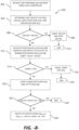
FIG. 8 , a flow diagram of an embodiment of amethod 300 for operating a power generation system is illustrated in accordance with aspects of the present subject matter. In general, themethod 300 is described herein as implemented using awind turbine system 100, such as the DFIG windturbine power system 100 described above. However, it should be appreciated that the disclosedmethod 300 may be implemented using any other suitable power generation system that is configured to supply power, including reactive power, for application to a load, such as a power grid. In addition, althoughFIG. 8 depicts steps performed in a particular order for purposes of illustration and discussion, the methods described herein are not limited to any particular order or arrangement. One skilled in the art, using the disclosures provided herein, will appreciate that various steps of the methods can be omitted, rearranged, combined and/or adapted in various ways. - At (302), the
method 300 includes receiving a reactive power command (Qcmd) at the wind turbine power system, wherein (Qcmd) may be generated by a farm-level controller in a wind farm. - At (304), the reactive power capacity is determined for each of the reactive power compensation device (Qmvb), the generator stator-side (Qs), and the generator line-side (Ql) at the wind turbine power system.
- At (306), a determination is made of whether the capacity of the reactive power compensation device (Qmvb) can satisfy the (Qcmd) demand. If so, at (308), the local controller 176 (or the
converter controller 174, as discussed above) allocates up to the maximum of (Qmvb) to supply (Qcmd), and the process ends at (310) until a new (Qcmd) demand is generated. - If (Qmvb) cannot fully supply the (Qcmd) demand, then at (312) the maximum capacity of (Qmvb) is allocated to (Qcmd) and the deficit amount of reactive power to be supplied by the generator/power converter [(Qs) and/or (Ql)] is determined (Qdef = Qcmd - Qmvb).
- At (314), a determination is made of whether the maximum capacity of (Qs) can satisfy (Qdef). If so, at (316), the local controller 176 (or the
converter controller 174, as discussed above) allocates up to the maximum capacity of (Qs) to satisfy (Qdef), and the process ends at (318) until a new (Qcmd) demand is generated. - If (Qdef) is greater than the max capacity of (Qs), then at step (320) the maximum of (Ql) is also allocated to (Qdef).
- At (322), if (Qcmd) is satisfied by (Qmvb) + (Qs) + (Ql), then the process ends at (324) until a new (Qcmd) is generated.
- If (Qcmd) cannot be satisfied by (Qmvb) + (Qs) + (Ql), then a final deficit (Qdef) is computed at (326) and the system switches to a VAR deficit Mode wherein real power production from the
system 100 is decreased so that reactive power production can increase. - The maximum reactive power capacities for (Qmvb), (Qs), and (Ql) are determined in real-time based on any one or combination of: power system operating state; ambient temperature; or thermal constraints of the generator; power converter, or reactive power compensation device. The values for (Qmvb), (Qs), and (Ql) may be continuously or periodically determined and updated in the control system.
- This written description uses examples to disclose the invention, including the best mode, and also to enable any person skilled in the art to practice the invention, including making and using any devices or systems and performing any incorporated methods. The patentable scope of the invention is defined by the claims, and may include other examples that occur to those skilled in the art. Such other examples are intended to be within the scope of the claims if they include structural elements that do not differ from the literal language of the claims, or if they include equivalent structural elements.
Claims (14)
- A method for operating a power generation system (10) that supplies real and reactive power to a grid, the power generation system (10) including a generator (120) with a power converter (162), and a dedicated reactive power compensation device (200), the method comprising:receiving a total reactive power demand, Qcmd, made on the power generation system (10) at an operating state of the power generation system (10) and grid state;determining a maximum reactive power capacity for each of a generator stator side reactive power, Qs, a generator line-side reactive power, Ql, and reactive power from the reactive power compensation device, Qmvb;coordinating supply of Qcmd from between Qs, Ql, and Qmvb at the operating state of the power generation system (10) and the grid state by prioritizing Qmvb as a first source of reactive power, and one or both of Qs and Ql as a second source of reactive power, wherein coordinating the supply comprises, when Qcmd is greater than the maximum capacity of Qmvb, then the maximum capacity of Qmvb is supplied and a deficiency between Qcmd and Qmvb is allocated to one or both of Qs and Ql, wherein Qs has priority over Ql such that the deficiency between Qcmd and Qmvb is first allocated up to the maximum capacity of Qs, and then to Ql.
- The method as in claim 1, wherein in the coordinating step, when Qcmd is less than the maximum capacity of Qmvb, then all of Qcmd is supplied by Qmvb.
- The method as in any preceding claim, wherein the maximum reactive power capacities for Qmvb, Qs, and Ql are continuously or periodically determined based on any one or combination of: power system operating state; ambient temperature; or thermal constraints of the generator; power converter, or reactive power compensation device.
- The method as in any preceding claim, wherein the power generation system (10) comprises a wind turbine (10) with a doubly fed induction generator, DFIG, system, and wherein Qcmd is a reactive power demand made on the wind turbine.
- The method as in claim 4, wherein the wind turbine (10) is one of a plurality of wind turbines within a wind farm that supplies real and reactive power to the grid, and wherein Qcmd is determined by a field-level controller within the wind farm and transmitted to a local controller at the wind turbine (10).
- The method as in any of claims 4-5, wherein the local controller allocates Qmvb to the reactive power compensation device (200) and allocates Qs, and Ql to the power converter.
- The method as in any of claims 5-6, wherein the local controller transmits Qcmd to a converter controller associated with the power converter, wherein the converter controller allocates Qmvb to the reactive power compensation device (200) and controls operation of the power converter to generate Qs, and Ql.
- A wind turbine system (100) configured to supply real and reactive power to a grid, comprising:a wind turbine (10) with a rotor, hub, and a plurality of blades coupled to the hub;a doubly fed induction generator system, DFIG system, coupled to the rotor, the DFIG system (120) further comprising a power converter (162) with a line side converter, LSC, and a rotor side converter, RSC, wherein the DFIG system is configured to generate a generator stator-side reactive power, Qs, and a generator line-side reactive power, Ql;a dedicated reactive power compensation device (200) operationally configured with the DFIG system (120) to generate a reactive power, Qmvb;a control system (176) configured to:receive a reactive power command, Qcmd, made on the wind turbine system (100);determine a maximum reactive power capacity for each of Qs, Ql, and Qmvb at an operating state of the wind turbine system (100) and a grid state; andcoordinate supply of reactive power between Qs, Ql, and Qmvb at the operating state of the wind turbine system and the grid state to meet Qcmd by prioritizing Qmvb as a first source of reactive power, and one or both of Qs and Ql as a second source of reactive power, wherein the control system (176) is configured to coordinate the supply such that, when Qcmd is greater than the maximum capacity of Qmvb, then the maximum capacity of Qmvb is supplied and a deficiency between Qcmd and Qmvb is allocated to one or both of Qs and Ql, wherein Qs has priority over Ql such that the deficiency between Qcmd and Qmvb is first allocated up to the maximum capacity of Qs, and then to Ql.
- The wind turbine system (100) as in claim 8, wherein the wind turbine (10) is one of a plurality of wind turbines within a wind farm that supplies real and reactive power to the grid, the control system (176) comprising a field-level controller in the wind farm that is configured to determine and transmit Qcmd, and a local controller at the wind turbine (10) is configured to receive the Qcmd transmitted by the field-level controller.
- The wind turbine system (100) as in any of claims 8-9, wherein to meet Qcmd, the local controller is configured to allocate Qmvb to the reactive power compensation device (200) and to allocate Qs, and Ql to the power converter.
- The wind turbine system (100) as in any of claims 8-10, wherein the reactive power compensation device (200) comprises any one or combination of a Static VAR compensator, SVC, a Static VAR Generator, SVG, device, or a Static Synchronous Compensator, STATCOM, device.
- The wind turbine system (100) as in any of claims 8-11, wherein the control system (176) is configured to supply all of Qcmd with Qmvb when Qcmd is less than the maximum capacity of Qmvb and allocate a deficiency between Qcmd and Qmvb to one or both of Qs and Ql.
- The wind turbine system (100) as in any of claims 8-12, wherein the control system (176) is configured to determine the maximum reactive power capacities for Qmvb, Qs, and Ql based on any one or combination of: power system operating state; ambient temperature; or thermal constraints of the generator; power converter, or reactive power compensation device (200).
- The wind turbine system (100) as in any of claims 8-13, wherein the control system (176) is configured to continuously or periodically determine the maximum reactive power capacities for Qmvb, Qs, and Ql.
Applications Claiming Priority (1)
| Application Number | Priority Date | Filing Date | Title |
|---|---|---|---|
| US16/403,789 US10731628B1 (en) | 2019-05-06 | 2019-05-06 | System and method for coordinated control of reactive power from a generator and a reactive power compensation device in a wind turbine system |
Publications (2)
| Publication Number | Publication Date |
|---|---|
| EP3736940A1 EP3736940A1 (en) | 2020-11-11 |
| EP3736940B1 true EP3736940B1 (en) | 2023-03-22 |
Family
ID=70553929
Family Applications (1)
| Application Number | Title | Priority Date | Filing Date |
|---|---|---|---|
| EP20173047.0A Active EP3736940B1 (en) | 2019-05-06 | 2020-05-05 | System and method for coordinated control of reactive power from a generator and a reactive power compensation device in a wind turbine system |
Country Status (4)
| Country | Link |
|---|---|
| US (1) | US10731628B1 (en) |
| EP (1) | EP3736940B1 (en) |
| DK (1) | DK3736940T3 (en) |
| ES (1) | ES2948202T3 (en) |
Families Citing this family (1)
| Publication number | Priority date | Publication date | Assignee | Title |
|---|---|---|---|---|
| CN114188977B (en) * | 2021-12-01 | 2023-09-01 | 国网山西省电力公司电力科学研究院 | Reactive power coordination control method of doubly-fed wind generator set |
Family Cites Families (44)
| Publication number | Priority date | Publication date | Assignee | Title |
|---|---|---|---|---|
| US904607A (en) | 1908-03-16 | 1908-11-24 | Hjalmar Elmblad | Seal-lock. |
| US5952816A (en) * | 1995-04-21 | 1999-09-14 | General Electric Co. | Compensation for power transfer systems using variable rotary transformer |
| US10135253B2 (en) * | 2000-12-29 | 2018-11-20 | Abb Schweiz Ag | System, method and computer program product for enhancing commercial value of electrical power produced from a renewable energy power production facility |
| US6670721B2 (en) * | 2001-07-10 | 2003-12-30 | Abb Ab | System, method, rotating machine and computer program product for enhancing electric power produced by renewable facilities |
| US7071579B2 (en) | 2002-06-07 | 2006-07-04 | Global Energyconcepts,Llc | Wind farm electrical system |
| US7245037B2 (en) | 2002-09-13 | 2007-07-17 | Abb Ab | Wind power fed network |
| US7095597B1 (en) | 2003-04-30 | 2006-08-22 | Clipper Windpower Technology, Inc. | Distributed static var compensation (DSVC) system for wind and water turbine applications |
| US6924565B2 (en) | 2003-08-18 | 2005-08-02 | General Electric Company | Continuous reactive power support for wind turbine generators |
| US7119452B2 (en) | 2003-09-03 | 2006-10-10 | General Electric Company | Voltage control for wind generators |
| US7013203B2 (en) | 2003-10-22 | 2006-03-14 | General Electric Company | Wind turbine system control |
| US7567160B2 (en) | 2006-02-15 | 2009-07-28 | American Superconductor Corporation | Supplementary transformer cooling in a reactive power compensation system |
| US8044527B2 (en) * | 2007-09-26 | 2011-10-25 | General Electric Company | Electric power generation with magnetically geared machine |
| WO2010116840A1 (en) * | 2009-03-30 | 2010-10-14 | 新日本製鐵株式会社 | Induction motor control device and induction motor group control system |
| EP2461452A4 (en) | 2009-07-27 | 2017-01-04 | Gamesa Innovation & Technology, S.L. | System for reactive power compensation in electricity system |
| WO2011032265A1 (en) * | 2009-09-15 | 2011-03-24 | The University Of Western Ontario | Utilization of distributed generator inverters as statcom |
| US7923862B2 (en) | 2009-10-06 | 2011-04-12 | General Electric Company | Reactive power regulation and voltage support for renewable energy plants |
| US9236742B2 (en) | 2010-02-25 | 2016-01-12 | Vestas Wind Systems A/S | Method and control arrangement for controlling a reactive power source |
| AU2011260701B2 (en) | 2010-06-03 | 2015-08-20 | Vestas Wind Systems A/S | Method and control arrangement for controlling central capacitors in wind power plants |
| US8664800B2 (en) | 2010-08-31 | 2014-03-04 | General Electric Company | System and method for distribution of inverter VAR support |
| EP2621071A4 (en) * | 2010-09-22 | 2017-05-17 | Toshiba Mitsubishi-Electric Industrial Systems Corporation | Power conversion device |
| US8093741B2 (en) * | 2010-10-29 | 2012-01-10 | General Electric Company | Method and system for providing increased turbine output for doubly fed induction generator |
| US8121739B2 (en) * | 2010-12-29 | 2012-02-21 | Vestas Wind Systems A/S | Reactive power management for wind power plant internal grid |
| DK2503146T3 (en) | 2011-03-21 | 2014-02-10 | Siemens Ag | Method and device for controlling the operation of an electric power generation plant during a disconnection from a supply network |
| WO2012178176A1 (en) | 2011-06-23 | 2012-12-27 | Inventus Holdings, Llc | Multiple renewables site electrical generation and reactive power control |
| US10571948B2 (en) * | 2012-08-09 | 2020-02-25 | Rajiv Kumar Varma | Use of distributed generator (DG) inverters as STATCOMs for decreasing line losses |
| US8664788B1 (en) * | 2012-09-07 | 2014-03-04 | General Electric Company | Method and systems for operating a wind turbine using dynamic braking in response to a grid event |
| CN104620458B (en) | 2012-09-17 | 2017-07-04 | 维斯塔斯风力系统集团公司 | Determine the method and power plant controller of each set point in power plant controller |
| US9556852B2 (en) | 2012-09-17 | 2017-01-31 | Vestas Wind Systems A/S | Method of determining individual set points in a power plant controller, and a power plant controller |
| CN102882229B (en) | 2012-09-21 | 2015-06-17 | 北京金风科创风电设备有限公司 | Automatic control system for dynamic voltage of wind power plant |
| EP2741392A3 (en) | 2012-12-04 | 2016-12-14 | ABB Research Ltd. | Systems and methods for utilizing an active compensator to augment a diode rectifier |
| US9680307B2 (en) | 2012-12-21 | 2017-06-13 | General Electric Company | System and method for voltage regulation of a renewable energy plant |
| WO2014124644A1 (en) | 2013-02-15 | 2014-08-21 | Vestas Wind Systems A/S | A method of operating a wind turbine plant |
| CN103368187A (en) * | 2013-07-12 | 2013-10-23 | 上海电力学院 | Reactive coordination control method based on improved wind generating set |
| US20150027068A1 (en) | 2013-07-24 | 2015-01-29 | General Electric Company | Tower base assembly for a wind turbine |
| EP3075054B1 (en) | 2013-11-28 | 2019-01-09 | Vestas Wind Systems A/S | Reconfiguration of the reactive power loop of a wind power plant |
| US9419439B2 (en) | 2014-01-14 | 2016-08-16 | Siemens Aktiengesellschaft | Reconnecting a wind power plant to a utility grid |
| US9780710B2 (en) | 2014-04-15 | 2017-10-03 | General Electric Company | Reactive power control for wind turbine generators |
| ES2690350T3 (en) * | 2014-06-13 | 2018-11-20 | Nordex Energy Gmbh | Procedure for regulating a wind turbine during an asymmetric grid error |
| WO2016059263A1 (en) * | 2014-10-16 | 2016-04-21 | Ingeteam Power Technology, S.A. | Kit for a wind station, and method |
| US10104814B2 (en) | 2014-11-03 | 2018-10-16 | General Electric Company | System and method for cooling electrical components of a power converter |
| US9831810B2 (en) | 2015-03-10 | 2017-11-28 | General Electric Company | System and method for improved reactive power speed-of-response for a wind farm |
| US10063174B2 (en) * | 2016-08-08 | 2018-08-28 | General Electric Company | System and method for controlling a negative sequence current in a wind turbine generator |
| US20180048157A1 (en) * | 2016-08-15 | 2018-02-15 | General Electric Company | Power generation system and related method of operating the power generation system |
| EP3552291B1 (en) * | 2016-12-09 | 2021-06-16 | Vestas Wind Systems A/S | Improvements relating to reactive power support in wind power plants |
-
2019
- 2019-05-06 US US16/403,789 patent/US10731628B1/en active Active
-
2020
- 2020-05-05 ES ES20173047T patent/ES2948202T3/en active Active
- 2020-05-05 DK DK20173047.0T patent/DK3736940T3/en active
- 2020-05-05 EP EP20173047.0A patent/EP3736940B1/en active Active
Also Published As
| Publication number | Publication date |
|---|---|
| EP3736940A1 (en) | 2020-11-11 |
| DK3736940T3 (en) | 2023-06-19 |
| US10731628B1 (en) | 2020-08-04 |
| ES2948202T3 (en) | 2023-09-01 |
Similar Documents
| Publication | Publication Date | Title |
|---|---|---|
| US10581247B1 (en) | System and method for reactive power control of wind turbines in a wind farm supported with auxiliary reactive power compensation | |
| EP2876769B1 (en) | System and method for operating a power generation system within a power storage/discharge mode or a dynamic brake mode | |
| US10742149B1 (en) | System and method for reactive power control of a wind turbine by varying switching frequency of rotor side converter | |
| EP3736938B1 (en) | Method for reactive power oscillation damping for a wind turbine system with integrated reactive power compensation device | |
| US20180309318A1 (en) | Energy Storage System for Doubly Fed Induction Generator | |
| EP3745553B1 (en) | System and method for operating a wind farm during low wind speeds | |
| EP3736935A1 (en) | Wind turbine system with integrated reactive power compensation device | |
| EP3971414A1 (en) | Grid-forming control of inverter-based resource using virtual impedance | |
| EP3893383A1 (en) | System and method for controlling wind turbine converters during high voltage ride through events | |
| EP3736940B1 (en) | System and method for coordinated control of reactive power from a generator and a reactive power compensation device in a wind turbine system | |
| EP3796505A1 (en) | System and method for control of reactive power from a reactive power compensation device in a wind turbine system | |
| EP3786447A1 (en) | System and method for operating a wind turbine power system during low wind speeds to improve efficiency | |
| US11682990B2 (en) | System and method for dynamically estimating active power capability of an inverter-based resource | |
| EP4009473A1 (en) | System and method for providing grid-forming control for a double-fed wind turbine generator using virtual impedance | |
| EP4220883A1 (en) | System and method for providing grid-forming control of an inverter-based resource | |
| EP4012874A1 (en) | System and method for operating an asynchronous inverter-based resource as a virtual synchronous machine with storage | |
| EP4012918A1 (en) | System and method for operating an asynchronous inverter-based resource as a virtual synchronous machine to provide grid-forming control thereof | |
| WO2024091249A1 (en) | System and method for extending the operating speed threshold of a grid-forming inverter-based resource | |
| WO2024112316A1 (en) | System and method for providing blackstart of grid-forming inverter-based resources |
Legal Events
| Date | Code | Title | Description |
|---|---|---|---|
| PUAI | Public reference made under article 153(3) epc to a published international application that has entered the european phase |
Free format text: ORIGINAL CODE: 0009012 |
|
| STAA | Information on the status of an ep patent application or granted ep patent |
Free format text: STATUS: THE APPLICATION HAS BEEN PUBLISHED |
|
| AK | Designated contracting states |
Kind code of ref document: A1 Designated state(s): AL AT BE BG CH CY CZ DE DK EE ES FI FR GB GR HR HU IE IS IT LI LT LU LV MC MK MT NL NO PL PT RO RS SE SI SK SM TR |
|
| AX | Request for extension of the european patent |
Extension state: BA ME |
|
| STAA | Information on the status of an ep patent application or granted ep patent |
Free format text: STATUS: REQUEST FOR EXAMINATION WAS MADE |
|
| 17P | Request for examination filed |
Effective date: 20210323 |
|
| RBV | Designated contracting states (corrected) |
Designated state(s): AL AT BE BG CH CY CZ DE DK EE ES FI FR GB GR HR HU IE IS IT LI LT LU LV MC MK MT NL NO PL PT RO RS SE SI SK SM TR |
|
| STAA | Information on the status of an ep patent application or granted ep patent |
Free format text: STATUS: EXAMINATION IS IN PROGRESS |
|
| 17Q | First examination report despatched |
Effective date: 20210730 |
|
| GRAP | Despatch of communication of intention to grant a patent |
Free format text: ORIGINAL CODE: EPIDOSNIGR1 |
|
| STAA | Information on the status of an ep patent application or granted ep patent |
Free format text: STATUS: GRANT OF PATENT IS INTENDED |
|
| INTG | Intention to grant announced |
Effective date: 20220322 |
|
| GRAJ | Information related to disapproval of communication of intention to grant by the applicant or resumption of examination proceedings by the epo deleted |
Free format text: ORIGINAL CODE: EPIDOSDIGR1 |
|
| STAA | Information on the status of an ep patent application or granted ep patent |
Free format text: STATUS: EXAMINATION IS IN PROGRESS |
|
| INTC | Intention to grant announced (deleted) | ||
| GRAP | Despatch of communication of intention to grant a patent |
Free format text: ORIGINAL CODE: EPIDOSNIGR1 |
|
| STAA | Information on the status of an ep patent application or granted ep patent |
Free format text: STATUS: GRANT OF PATENT IS INTENDED |
|
| INTG | Intention to grant announced |
Effective date: 20221014 |
|
| GRAS | Grant fee paid |
Free format text: ORIGINAL CODE: EPIDOSNIGR3 |
|
| GRAA | (expected) grant |
Free format text: ORIGINAL CODE: 0009210 |
|
| STAA | Information on the status of an ep patent application or granted ep patent |
Free format text: STATUS: THE PATENT HAS BEEN GRANTED |
|
| AK | Designated contracting states |
Kind code of ref document: B1 Designated state(s): AL AT BE BG CH CY CZ DE DK EE ES FI FR GB GR HR HU IE IS IT LI LT LU LV MC MK MT NL NO PL PT RO RS SE SI SK SM TR |
|
| REG | Reference to a national code |
Ref country code: GB Ref legal event code: FG4D |
|
| REG | Reference to a national code |
Ref country code: CH Ref legal event code: EP |
|
| REG | Reference to a national code |
Ref country code: DE Ref legal event code: R096 Ref document number: 602020008949 Country of ref document: DE |
|
| REG | Reference to a national code |
Ref country code: IE Ref legal event code: FG4D |
|
| REG | Reference to a national code |
Ref country code: AT Ref legal event code: REF Ref document number: 1555875 Country of ref document: AT Kind code of ref document: T Effective date: 20230415 |
|
| REG | Reference to a national code |
Ref country code: DK Ref legal event code: T3 Effective date: 20230614 |
|
| REG | Reference to a national code |
Ref country code: LT Ref legal event code: MG9D |
|
| P01 | Opt-out of the competence of the unified patent court (upc) registered |
Effective date: 20230530 |
|
| REG | Reference to a national code |
Ref country code: NL Ref legal event code: MP Effective date: 20230322 |
|
| PG25 | Lapsed in a contracting state [announced via postgrant information from national office to epo] |
Ref country code: RS Free format text: LAPSE BECAUSE OF FAILURE TO SUBMIT A TRANSLATION OF THE DESCRIPTION OR TO PAY THE FEE WITHIN THE PRESCRIBED TIME-LIMIT Effective date: 20230322 Ref country code: NO Free format text: LAPSE BECAUSE OF FAILURE TO SUBMIT A TRANSLATION OF THE DESCRIPTION OR TO PAY THE FEE WITHIN THE PRESCRIBED TIME-LIMIT Effective date: 20230622 Ref country code: LV Free format text: LAPSE BECAUSE OF FAILURE TO SUBMIT A TRANSLATION OF THE DESCRIPTION OR TO PAY THE FEE WITHIN THE PRESCRIBED TIME-LIMIT Effective date: 20230322 Ref country code: LT Free format text: LAPSE BECAUSE OF FAILURE TO SUBMIT A TRANSLATION OF THE DESCRIPTION OR TO PAY THE FEE WITHIN THE PRESCRIBED TIME-LIMIT Effective date: 20230322 Ref country code: HR Free format text: LAPSE BECAUSE OF FAILURE TO SUBMIT A TRANSLATION OF THE DESCRIPTION OR TO PAY THE FEE WITHIN THE PRESCRIBED TIME-LIMIT Effective date: 20230322 |
|
| PGFP | Annual fee paid to national office [announced via postgrant information from national office to epo] |
Ref country code: ES Payment date: 20230601 Year of fee payment: 4 Ref country code: DK Payment date: 20230621 Year of fee payment: 4 Ref country code: DE Payment date: 20230419 Year of fee payment: 4 |
|
| REG | Reference to a national code |
Ref country code: AT Ref legal event code: MK05 Ref document number: 1555875 Country of ref document: AT Kind code of ref document: T Effective date: 20230322 |
|
| PG25 | Lapsed in a contracting state [announced via postgrant information from national office to epo] |
Ref country code: SE Free format text: LAPSE BECAUSE OF FAILURE TO SUBMIT A TRANSLATION OF THE DESCRIPTION OR TO PAY THE FEE WITHIN THE PRESCRIBED TIME-LIMIT Effective date: 20230322 Ref country code: NL Free format text: LAPSE BECAUSE OF FAILURE TO SUBMIT A TRANSLATION OF THE DESCRIPTION OR TO PAY THE FEE WITHIN THE PRESCRIBED TIME-LIMIT Effective date: 20230322 Ref country code: GR Free format text: LAPSE BECAUSE OF FAILURE TO SUBMIT A TRANSLATION OF THE DESCRIPTION OR TO PAY THE FEE WITHIN THE PRESCRIBED TIME-LIMIT Effective date: 20230623 Ref country code: FI Free format text: LAPSE BECAUSE OF FAILURE TO SUBMIT A TRANSLATION OF THE DESCRIPTION OR TO PAY THE FEE WITHIN THE PRESCRIBED TIME-LIMIT Effective date: 20230322 |
|
| REG | Reference to a national code |
Ref country code: ES Ref legal event code: FG2A Ref document number: 2948202 Country of ref document: ES Kind code of ref document: T3 Effective date: 20230901 |
|
| PG25 | Lapsed in a contracting state [announced via postgrant information from national office to epo] |
Ref country code: SM Free format text: LAPSE BECAUSE OF FAILURE TO SUBMIT A TRANSLATION OF THE DESCRIPTION OR TO PAY THE FEE WITHIN THE PRESCRIBED TIME-LIMIT Effective date: 20230322 Ref country code: RO Free format text: LAPSE BECAUSE OF FAILURE TO SUBMIT A TRANSLATION OF THE DESCRIPTION OR TO PAY THE FEE WITHIN THE PRESCRIBED TIME-LIMIT Effective date: 20230322 Ref country code: PT Free format text: LAPSE BECAUSE OF FAILURE TO SUBMIT A TRANSLATION OF THE DESCRIPTION OR TO PAY THE FEE WITHIN THE PRESCRIBED TIME-LIMIT Effective date: 20230724 Ref country code: EE Free format text: LAPSE BECAUSE OF FAILURE TO SUBMIT A TRANSLATION OF THE DESCRIPTION OR TO PAY THE FEE WITHIN THE PRESCRIBED TIME-LIMIT Effective date: 20230322 Ref country code: AT Free format text: LAPSE BECAUSE OF FAILURE TO SUBMIT A TRANSLATION OF THE DESCRIPTION OR TO PAY THE FEE WITHIN THE PRESCRIBED TIME-LIMIT Effective date: 20230322 |
|
| REG | Reference to a national code |
Ref country code: GB Ref legal event code: 732E Free format text: REGISTERED BETWEEN 20231102 AND 20231108 |
|
| PG25 | Lapsed in a contracting state [announced via postgrant information from national office to epo] |
Ref country code: SK Free format text: LAPSE BECAUSE OF FAILURE TO SUBMIT A TRANSLATION OF THE DESCRIPTION OR TO PAY THE FEE WITHIN THE PRESCRIBED TIME-LIMIT Effective date: 20230322 Ref country code: PL Free format text: LAPSE BECAUSE OF FAILURE TO SUBMIT A TRANSLATION OF THE DESCRIPTION OR TO PAY THE FEE WITHIN THE PRESCRIBED TIME-LIMIT Effective date: 20230322 Ref country code: IS Free format text: LAPSE BECAUSE OF FAILURE TO SUBMIT A TRANSLATION OF THE DESCRIPTION OR TO PAY THE FEE WITHIN THE PRESCRIBED TIME-LIMIT Effective date: 20230722 |
|
| REG | Reference to a national code |
Representative=s name: ZIMMERMANN & PARTNER PATENTANWAELTE MBB, DE Ref country code: DE Ref legal event code: R082 Ref document number: 602020008949 Country of ref document: DE Ref country code: DE Ref legal event code: R081 Ref document number: 602020008949 Country of ref document: DE Owner name: GENERAL ELECTRIC RENOVABLES ESPANA, S.L., ES Free format text: FORMER OWNER: GENERAL ELECTRIC COMPANY, SCHENECTADY, NY, US |
|
| RAP2 | Party data changed (patent owner data changed or rights of a patent transferred) |
Owner name: GENERAL ELECTRIC RENOVABLES ESPANA, S.L. |
|
| REG | Reference to a national code |
Ref country code: CH Ref legal event code: PL |
|
| REG | Reference to a national code |
Ref country code: DE Ref legal event code: R097 Ref document number: 602020008949 Country of ref document: DE |
|
| PG25 | Lapsed in a contracting state [announced via postgrant information from national office to epo] |
Ref country code: MC Free format text: LAPSE BECAUSE OF FAILURE TO SUBMIT A TRANSLATION OF THE DESCRIPTION OR TO PAY THE FEE WITHIN THE PRESCRIBED TIME-LIMIT Effective date: 20230322 |
|
| PLBE | No opposition filed within time limit |
Free format text: ORIGINAL CODE: 0009261 |
|
| STAA | Information on the status of an ep patent application or granted ep patent |
Free format text: STATUS: NO OPPOSITION FILED WITHIN TIME LIMIT |
|
| REG | Reference to a national code |
Ref country code: BE Ref legal event code: MM Effective date: 20230531 |
|
| PG25 | Lapsed in a contracting state [announced via postgrant information from national office to epo] |
Ref country code: SI Free format text: LAPSE BECAUSE OF FAILURE TO SUBMIT A TRANSLATION OF THE DESCRIPTION OR TO PAY THE FEE WITHIN THE PRESCRIBED TIME-LIMIT Effective date: 20230322 Ref country code: MC Free format text: LAPSE BECAUSE OF FAILURE TO SUBMIT A TRANSLATION OF THE DESCRIPTION OR TO PAY THE FEE WITHIN THE PRESCRIBED TIME-LIMIT Effective date: 20230322 Ref country code: LU Free format text: LAPSE BECAUSE OF NON-PAYMENT OF DUE FEES Effective date: 20230505 Ref country code: LI Free format text: LAPSE BECAUSE OF NON-PAYMENT OF DUE FEES Effective date: 20230531 Ref country code: CZ Free format text: LAPSE BECAUSE OF FAILURE TO SUBMIT A TRANSLATION OF THE DESCRIPTION OR TO PAY THE FEE WITHIN THE PRESCRIBED TIME-LIMIT Effective date: 20230322 Ref country code: CH Free format text: LAPSE BECAUSE OF NON-PAYMENT OF DUE FEES Effective date: 20230531 |
|
| 26N | No opposition filed |
Effective date: 20240102 |
|
| REG | Reference to a national code |
Ref country code: IE Ref legal event code: MM4A |
|
| REG | Reference to a national code |
Ref country code: DE Ref legal event code: R082 Ref document number: 602020008949 Country of ref document: DE Representative=s name: ZIMMERMANN & PARTNER PATENTANWAELTE MBB, DE |
|
| PG25 | Lapsed in a contracting state [announced via postgrant information from national office to epo] |
Ref country code: IE Free format text: LAPSE BECAUSE OF NON-PAYMENT OF DUE FEES Effective date: 20230505 |
|
| PG25 | Lapsed in a contracting state [announced via postgrant information from national office to epo] |
Ref country code: IE Free format text: LAPSE BECAUSE OF NON-PAYMENT OF DUE FEES Effective date: 20230505 |