EP3685547B1 - Power delivery through an optical system - Google Patents
Power delivery through an optical system Download PDFInfo
- Publication number
- EP3685547B1 EP3685547B1 EP18780270.7A EP18780270A EP3685547B1 EP 3685547 B1 EP3685547 B1 EP 3685547B1 EP 18780270 A EP18780270 A EP 18780270A EP 3685547 B1 EP3685547 B1 EP 3685547B1
- Authority
- EP
- European Patent Office
- Prior art keywords
- power
- optical
- network
- optical transceiver
- data
- Prior art date
- Legal status (The legal status is an assumption and is not a legal conclusion. Google has not performed a legal analysis and makes no representation as to the accuracy of the status listed.)
- Active
Links
- 230000003287 optical effect Effects 0.000 title claims description 166
- 239000000835 fiber Substances 0.000 claims description 77
- 238000004891 communication Methods 0.000 claims description 47
- 238000001816 cooling Methods 0.000 claims description 22
- 238000000034 method Methods 0.000 claims description 19
- 239000013307 optical fiber Substances 0.000 claims description 14
- 238000002716 delivery method Methods 0.000 claims description 3
- 238000002788 crimping Methods 0.000 claims description 2
- 230000005540 biological transmission Effects 0.000 claims 2
- 238000012544 monitoring process Methods 0.000 claims 1
- RYGMFSIKBFXOCR-UHFFFAOYSA-N Copper Chemical compound [Cu] RYGMFSIKBFXOCR-UHFFFAOYSA-N 0.000 description 16
- 229910052802 copper Inorganic materials 0.000 description 13
- 239000010949 copper Substances 0.000 description 13
- 238000001514 detection method Methods 0.000 description 9
- 238000003780 insertion Methods 0.000 description 7
- 230000037431 insertion Effects 0.000 description 7
- 230000008569 process Effects 0.000 description 6
- 230000008901 benefit Effects 0.000 description 4
- 238000010586 diagram Methods 0.000 description 3
- 230000006870 function Effects 0.000 description 3
- 238000002955 isolation Methods 0.000 description 3
- 229910052751 metal Inorganic materials 0.000 description 3
- 239000002184 metal Substances 0.000 description 3
- XUIMIQQOPSSXEZ-UHFFFAOYSA-N Silicon Chemical compound [Si] XUIMIQQOPSSXEZ-UHFFFAOYSA-N 0.000 description 2
- 238000006243 chemical reaction Methods 0.000 description 2
- 230000009977 dual effect Effects 0.000 description 2
- 238000005516 engineering process Methods 0.000 description 2
- 239000004744 fabric Substances 0.000 description 2
- 238000009413 insulation Methods 0.000 description 2
- 239000000463 material Substances 0.000 description 2
- 230000013011 mating Effects 0.000 description 2
- 230000007246 mechanism Effects 0.000 description 2
- 230000011664 signaling Effects 0.000 description 2
- 229910052710 silicon Inorganic materials 0.000 description 2
- 239000010703 silicon Substances 0.000 description 2
- 238000012358 sourcing Methods 0.000 description 2
- 229910052782 aluminium Inorganic materials 0.000 description 1
- XAGFODPZIPBFFR-UHFFFAOYSA-N aluminium Chemical compound [Al] XAGFODPZIPBFFR-UHFFFAOYSA-N 0.000 description 1
- 239000002826 coolant Substances 0.000 description 1
- 230000008878 coupling Effects 0.000 description 1
- 238000010168 coupling process Methods 0.000 description 1
- 238000005859 coupling reaction Methods 0.000 description 1
- 230000001419 dependent effect Effects 0.000 description 1
- 238000013461 design Methods 0.000 description 1
- 238000009429 electrical wiring Methods 0.000 description 1
- 230000006855 networking Effects 0.000 description 1
- 230000037361 pathway Effects 0.000 description 1
- 238000012545 processing Methods 0.000 description 1
- 230000001681 protective effect Effects 0.000 description 1
- APTZNLHMIGJTEW-UHFFFAOYSA-N pyraflufen-ethyl Chemical compound C1=C(Cl)C(OCC(=O)OCC)=CC(C=2C(=C(OC(F)F)N(C)N=2)Cl)=C1F APTZNLHMIGJTEW-UHFFFAOYSA-N 0.000 description 1
- 239000003507 refrigerant Substances 0.000 description 1
- 239000004065 semiconductor Substances 0.000 description 1
- 239000004557 technical material Substances 0.000 description 1
- 230000007704 transition Effects 0.000 description 1
- XLYOFNOQVPJJNP-UHFFFAOYSA-N water Substances O XLYOFNOQVPJJNP-UHFFFAOYSA-N 0.000 description 1
Images


Classifications
-
- H—ELECTRICITY
- H04—ELECTRIC COMMUNICATION TECHNIQUE
- H04B—TRANSMISSION
- H04B10/00—Transmission systems employing electromagnetic waves other than radio-waves, e.g. infrared, visible or ultraviolet light, or employing corpuscular radiation, e.g. quantum communication
- H04B10/80—Optical aspects relating to the use of optical transmission for specific applications, not provided for in groups H04B10/03 - H04B10/70, e.g. optical power feeding or optical transmission through water
- H04B10/806—Arrangements for feeding power
- H04B10/807—Optical power feeding, i.e. transmitting power using an optical signal
-
- G—PHYSICS
- G02—OPTICS
- G02B—OPTICAL ELEMENTS, SYSTEMS OR APPARATUS
- G02B6/00—Light guides; Structural details of arrangements comprising light guides and other optical elements, e.g. couplings
- G02B6/24—Coupling light guides
- G02B6/42—Coupling light guides with opto-electronic elements
- G02B6/4292—Coupling light guides with opto-electronic elements the light guide being disconnectable from the opto-electronic element, e.g. mutually self aligning arrangements
- G02B6/4293—Coupling light guides with opto-electronic elements the light guide being disconnectable from the opto-electronic element, e.g. mutually self aligning arrangements hybrid electrical and optical connections for transmitting electrical and optical signals
-
- H—ELECTRICITY
- H02—GENERATION; CONVERSION OR DISTRIBUTION OF ELECTRIC POWER
- H02J—CIRCUIT ARRANGEMENTS OR SYSTEMS FOR SUPPLYING OR DISTRIBUTING ELECTRIC POWER; SYSTEMS FOR STORING ELECTRIC ENERGY
- H02J50/00—Circuit arrangements or systems for wireless supply or distribution of electric power
- H02J50/30—Circuit arrangements or systems for wireless supply or distribution of electric power using light, e.g. lasers
-
- H—ELECTRICITY
- H02—GENERATION; CONVERSION OR DISTRIBUTION OF ELECTRIC POWER
- H02J—CIRCUIT ARRANGEMENTS OR SYSTEMS FOR SUPPLYING OR DISTRIBUTING ELECTRIC POWER; SYSTEMS FOR STORING ELECTRIC ENERGY
- H02J50/00—Circuit arrangements or systems for wireless supply or distribution of electric power
- H02J50/80—Circuit arrangements or systems for wireless supply or distribution of electric power involving the exchange of data, concerning supply or distribution of electric power, between transmitting devices and receiving devices
-
- H—ELECTRICITY
- H04—ELECTRIC COMMUNICATION TECHNIQUE
- H04L—TRANSMISSION OF DIGITAL INFORMATION, e.g. TELEGRAPHIC COMMUNICATION
- H04L12/00—Data switching networks
- H04L12/02—Details
- H04L12/10—Current supply arrangements
-
- H—ELECTRICITY
- H04—ELECTRIC COMMUNICATION TECHNIQUE
- H04L—TRANSMISSION OF DIGITAL INFORMATION, e.g. TELEGRAPHIC COMMUNICATION
- H04L12/00—Data switching networks
- H04L12/02—Details
- H04L12/12—Arrangements for remote connection or disconnection of substations or of equipment thereof
-
- H—ELECTRICITY
- H04—ELECTRIC COMMUNICATION TECHNIQUE
- H04L—TRANSMISSION OF DIGITAL INFORMATION, e.g. TELEGRAPHIC COMMUNICATION
- H04L12/00—Data switching networks
- H04L12/28—Data switching networks characterised by path configuration, e.g. LAN [Local Area Networks] or WAN [Wide Area Networks]
- H04L12/40—Bus networks
- H04L12/40006—Architecture of a communication node
- H04L12/40045—Details regarding the feeding of energy to the node from the bus
-
- H—ELECTRICITY
- H04—ELECTRIC COMMUNICATION TECHNIQUE
- H04L—TRANSMISSION OF DIGITAL INFORMATION, e.g. TELEGRAPHIC COMMUNICATION
- H04L12/00—Data switching networks
- H04L12/28—Data switching networks characterised by path configuration, e.g. LAN [Local Area Networks] or WAN [Wide Area Networks]
- H04L12/40—Bus networks
- H04L12/40052—High-speed IEEE 1394 serial bus
- H04L12/40091—Bus bridging
-
- H—ELECTRICITY
- H04—ELECTRIC COMMUNICATION TECHNIQUE
- H04L—TRANSMISSION OF DIGITAL INFORMATION, e.g. TELEGRAPHIC COMMUNICATION
- H04L12/00—Data switching networks
- H04L12/28—Data switching networks characterised by path configuration, e.g. LAN [Local Area Networks] or WAN [Wide Area Networks]
- H04L12/40—Bus networks
- H04L12/40169—Flexible bus arrangements
- H04L12/40176—Flexible bus arrangements involving redundancy
-
- H—ELECTRICITY
- H04—ELECTRIC COMMUNICATION TECHNIQUE
- H04M—TELEPHONIC COMMUNICATION
- H04M19/00—Current supply arrangements for telephone systems
- H04M19/08—Current supply arrangements for telephone systems with current supply sources at the substations
-
- G—PHYSICS
- G01—MEASURING; TESTING
- G01J—MEASUREMENT OF INTENSITY, VELOCITY, SPECTRAL CONTENT, POLARISATION, PHASE OR PULSE CHARACTERISTICS OF INFRARED, VISIBLE OR ULTRAVIOLET LIGHT; COLORIMETRY; RADIATION PYROMETRY
- G01J3/00—Spectrometry; Spectrophotometry; Monochromators; Measuring colours
- G01J3/02—Details
- G01J3/0205—Optical elements not provided otherwise, e.g. optical manifolds, diffusers, windows
- G01J3/0218—Optical elements not provided otherwise, e.g. optical manifolds, diffusers, windows using optical fibers
-
- G—PHYSICS
- G02—OPTICS
- G02B—OPTICAL ELEMENTS, SYSTEMS OR APPARATUS
- G02B6/00—Light guides; Structural details of arrangements comprising light guides and other optical elements, e.g. couplings
- G02B6/24—Coupling light guides
- G02B6/36—Mechanical coupling means
- G02B6/38—Mechanical coupling means having fibre to fibre mating means
- G02B6/3807—Dismountable connectors, i.e. comprising plugs
- G02B6/381—Dismountable connectors, i.e. comprising plugs of the ferrule type, e.g. fibre ends embedded in ferrules, connecting a pair of fibres
- G02B6/3817—Dismountable connectors, i.e. comprising plugs of the ferrule type, e.g. fibre ends embedded in ferrules, connecting a pair of fibres containing optical and electrical conductors
-
- H—ELECTRICITY
- H02—GENERATION; CONVERSION OR DISTRIBUTION OF ELECTRIC POWER
- H02S—GENERATION OF ELECTRIC POWER BY CONVERSION OF INFRARED RADIATION, VISIBLE LIGHT OR ULTRAVIOLET LIGHT, e.g. USING PHOTOVOLTAIC [PV] MODULES
- H02S40/00—Components or accessories in combination with PV modules, not provided for in groups H02S10/00 - H02S30/00
- H02S40/30—Electrical components
- H02S40/38—Energy storage means, e.g. batteries, structurally associated with PV modules
-
- Y—GENERAL TAGGING OF NEW TECHNOLOGICAL DEVELOPMENTS; GENERAL TAGGING OF CROSS-SECTIONAL TECHNOLOGIES SPANNING OVER SEVERAL SECTIONS OF THE IPC; TECHNICAL SUBJECTS COVERED BY FORMER USPC CROSS-REFERENCE ART COLLECTIONS [XRACs] AND DIGESTS
- Y02—TECHNOLOGIES OR APPLICATIONS FOR MITIGATION OR ADAPTATION AGAINST CLIMATE CHANGE
- Y02D—CLIMATE CHANGE MITIGATION TECHNOLOGIES IN INFORMATION AND COMMUNICATION TECHNOLOGIES [ICT], I.E. INFORMATION AND COMMUNICATION TECHNOLOGIES AIMING AT THE REDUCTION OF THEIR OWN ENERGY USE
- Y02D30/00—Reducing energy consumption in communication networks
- Y02D30/50—Reducing energy consumption in communication networks in wire-line communication networks, e.g. low power modes or reduced link rate
-
- Y—GENERAL TAGGING OF NEW TECHNOLOGICAL DEVELOPMENTS; GENERAL TAGGING OF CROSS-SECTIONAL TECHNOLOGIES SPANNING OVER SEVERAL SECTIONS OF THE IPC; TECHNICAL SUBJECTS COVERED BY FORMER USPC CROSS-REFERENCE ART COLLECTIONS [XRACs] AND DIGESTS
- Y02—TECHNOLOGIES OR APPLICATIONS FOR MITIGATION OR ADAPTATION AGAINST CLIMATE CHANGE
- Y02E—REDUCTION OF GREENHOUSE GAS [GHG] EMISSIONS, RELATED TO ENERGY GENERATION, TRANSMISSION OR DISTRIBUTION
- Y02E10/00—Energy generation through renewable energy sources
- Y02E10/50—Photovoltaic [PV] energy
-
- Y—GENERAL TAGGING OF NEW TECHNOLOGICAL DEVELOPMENTS; GENERAL TAGGING OF CROSS-SECTIONAL TECHNOLOGIES SPANNING OVER SEVERAL SECTIONS OF THE IPC; TECHNICAL SUBJECTS COVERED BY FORMER USPC CROSS-REFERENCE ART COLLECTIONS [XRACs] AND DIGESTS
- Y02—TECHNOLOGIES OR APPLICATIONS FOR MITIGATION OR ADAPTATION AGAINST CLIMATE CHANGE
- Y02E—REDUCTION OF GREENHOUSE GAS [GHG] EMISSIONS, RELATED TO ENERGY GENERATION, TRANSMISSION OR DISTRIBUTION
- Y02E70/00—Other energy conversion or management systems reducing GHG emissions
- Y02E70/30—Systems combining energy storage with energy generation of non-fossil origin
Definitions
- the present disclosure relates generally to communications networks, and more particularly, to power delivery in a communications network.
- PoE Power over Ethernet
- PSE power sourcing equipment
- PD powered device
- PoE Power over Ethernet
- PSE power sourcing equipment
- PD powered device
- PoE power is delivered over the cables used by the data over a range from a few meters to about one hundred meters.
- PSE power sourcing equipment
- PD powered device
- PoE power must be supplied through a local power source such as a wall outlet due to limitations with conventional PoE.
- today's PoE systems have limited power capacity, which may be inadequate for many classes of devices.
- US 2015/078740 A1 discloses a fiber optic-based communications network including: a power insertion device, connected to multiple fiber links from a data source, configured to provide power insertion to a hybrid fiber/power cable connected to at least one fiber link of the multiple fiber links; the hybrid fiber/power cable, connecting the power insertion device to a connection interface device, configured to transmit data and power from the power insertion device to the connection interface device; and the connection interface device, configured to provide an interface for connection to an end device via a power over Ethernet (PoE)-compatible connection and to provide optical to electrical media conversion for data transmitted from the power insertion device to an end device via the hybrid fiber/power cable and the PoE-compatible connection.
- PoE power over Ethernet
- PoE Power over Ethernet
- the embodiments described herein provide power delivery through an optical transceiver by supplying power integrated with fiber cabling over the same fiber/optical transceiver system so that power may be supplied at greater distances (e.g., up to 10 km), in greater quantity (e.g., up to several kilowatts), and may be provided in locations where local power is difficult to deliver.
- power may be supplied at greater distances (e.g., up to 10 km), in greater quantity (e.g., up to several kilowatts), and may be provided in locations where local power is difficult to deliver.
- power does not need to be supplied throughout a data center room and a full zoned system may be deployed without building out a data room.
- the embodiments effectively deliver communications and power on a large enough scale that equipment in a data room can entirely be powered from an equipment/premise entrance point of the building.
- electrical power distribution equipment may be removed from the floor data room and switches, routers, access points, lighting systems, and other electronic devices or equipment may be placed outside of the 100 m range of traditional PoE systems.
- power can be delivered to equipment in a zone, data room on a floor, or an access point anywhere in the building.
- IoT Internet of Things
- networks e.g., switch/router
- PoE + Fiber The system is referred to herein as PoE + Fiber (PoE+F).
- the embodiments operate in the context of a data communications network including multiple network devices.
- the network may include any number of network devices in communication via any number of nodes (e.g., routers, switches, gateways, controllers, access points, or other network devices), which facilitate passage of data within the network.
- nodes e.g., routers, switches, gateways, controllers, access points, or other network devices
- the network devices may communicate over or be in communication with one or more networks (e.g., local area network (LAN), metropolitan area network (MAN), wide area network (WAN), virtual private network (VPN) (e.g., Ethernet virtual private network (EVPN), layer 2 virtual private network (L2VPN)), virtual local area network (VLAN), wireless network, enterprise network, corporate network, data center, Internet of Things (IoT), Internet, intranet, or any other network).
- networks e.g., local area network (LAN), metropolitan area network (MAN), wide area network (WAN), virtual private network (VPN) (e.g., Ethernet virtual private network (EVPN), layer 2 virtual private network (L2VPN)), virtual local area network (VLAN), wireless network, enterprise network, corporate network, data center, Internet of Things (IoT), Internet, intranet, or any other network).
- networks e.g., local area network (LAN), metropolitan area network (MAN), wide area network (WAN), virtual private network (VPN) (e.g., Ethernet virtual private network (EV
- the network is configured to pass electrical power along with optical data to provide both data connectivity and electric power to network devices such as switches, routers, access points, or other electronic components and devices. Signals may be exchanged among communications equipment and power transmitted from power sourcing equipment to powered devices.
- the PoE+F system delivers power to and from a network (e.g., switch/router system) using an optical transceiver (optical module) configured to receive and transmit both data and electrical power, and a cabling system comprising both optical fibers and electrical wires (e.g., copper wires).
- the PoE+F system uses building power supplied to a network device 10, which may be located in a premise/entry room, for example.
- the power may be transmitted from the building entry point to end points, which may be located at distances greater than 100 meters (e.g., 1 km, 10 km, or any other distance), and/or at greater power levels than 100 Watts (e.g., 250 Watts, 1000 Watts or any other power level).
- the network device 10 comprises a power supply unit (PSU) 11 for receiving power (e.g., building power), a fabric 12, and a plurality of line cards 13.
- PSU power supply unit
- one of the line cards receives fiber from outside of the building (e.g., from street or other location) and the other line cards implement PoE+F.
- the network device 10 is operable to provide high capacity power from an internal power system (e.g., PSU providing over and including 5 kW (e.g., 10 kW, 12 kW, 14 kW, 16 kW), or PSU providing over and including 100 W (e.g., 500 W, 1 kW) of useable power or any other suitable power capacity).
- the PSU 11 may provide, for example, PoE, pulsed power, or AC power.
- the network device 10 is operable to receive power external from a communications network and transmit the power over data fiber cables 18 in the communications network (e.g., network comprising central hub 10 (PSE) and a plurality of network devices 14, 15 (PDs).
- the network device 10 may comprise, for example, a router or convergence device (e.g., Network Convergence System (NCS) 4000 series available from Cisco Systems, Inc.) or any other suitable line card system. It is to be understood that this is only an example and any other network device operable to transmit power and optical data may be used.
- One or more of the line cards 13 may also include an optical transceiver module 16 operable to transmit power and data on the cables 18.
- the network may include any number or arrangement of network communications devices (e.g., switches 14, access points 15, routers, or other devices operable to route (switch, forward) data communications).
- each group of access points 15 is located on a different floor or zone.
- One or more network devices 14, 15 may also deliver power to equipment using PoE, as described below with respect to Figures 3 and 4 .
- one or more of the network devices 14, 15 may deliver power using PoE to electronic components such as IP (Internet Protocol) cameras, VoIP (Voice over IP) phones, video cameras, point-of-sale devices, security access control devices, residential devices, building automation devices, industrial automation, factory equipment, lights (building lights, streetlights), traffic signals, and many other electrical components and devices.
- IP Internet Protocol
- VoIP Voice over IP
- Cables 18 extending from the network device 10 to the switches 14 and access points 15 are configured to transmit power over data fiber cabling and include both optical fibers and electrical wires.
- the cables 18 comprise two copper wires and two fibers.
- the cables 18 may be formed from any material suitable to carry both electrical power and optical data (e.g., copper, fiber) and may carry any number of electrical wires and optical fibers in any arrangement. As described below with respect to Figures 15 -18, the cables 18 may also include cooling.
- optical transceivers optical module, optical device, optics module, transceiver, silicon photonics optical transceiver 16 are configured to source or receive power, as described in detail below.
- the transceiver modules 16 operate as an engine that bidirectionally converts optical signals to electrical signals or in general as an interface to the network element copper wire or optical fiber.
- the optical transceiver 16 may be a pluggable transceiver module in any form factor (e.g., SFP (Small Form-Factor Pluggable), QSFP (Quad Small Form-Factor Pluggable), CFP (C Form-Factor Pluggable), and the like), and may support data rates up to 400 Gbps, for example.
- Hosts for these pluggable optical modules include line cards on the switches 14, access points 15, or other network devices.
- One or more of the line cards 13 in network device 10 may also host optical modules.
- the host may include a printed circuit board (PCB) and electronic components and circuits operable to interface telecommunications lines in a telecommunications network.
- the host may be configured to perform one or more operations and receive any number or type of pluggable transceiver modules configured for transmitting and receiving signals.
- PCB printed circuit board
- the optical transceiver 16 may also be configured for operation with AOC (Active Optical Cable) and form factors used in UWB (Ultra-Wideband) applications, including for example, Ultra HDMI (High-Definition Multimedia Interface), serial high bandwidth cables (e.g., thunderbolt), and other form factors.
- AOC Active Optical Cable
- UWB Ultra-Wideband
- form factors used in UWB (Ultra-Wideband) applications, including for example, Ultra HDMI (High-Definition Multimedia Interface), serial high bandwidth cables (e.g., thunderbolt), and other form factors.
- optical transceivers 16 may be configured for operation in point-to-multipoint or multipoint-to-point topology.
- QFSP may breakout to SFP+.
- One or more embodiments may be configured to allow for load shifting.
- the optical transceiver 16 is modified along with a fiber connector system to incorporate copper wires to deliver power through the optical transceiver to the powered devices 14, 15 for use by the network communications devices.
- the optical transceiver 16 provides for power to be delivered to the switches 14 and access points 15 in locations where standard power is not available.
- the optical transceiver 16 may be configured to tap some of the energy and make intelligent decisions so that the power source 10 knows when it is safe to increase power on the wires without damaging the system or endangering an operator.
- one or more network devices may comprise dual-role power ports that may be selectively configurable to operate as a PSE (Power Source Equipment) port to provide power to a connected device or as a PD (Powered Device) port to sink power from the connected device, and enable the reversal of energy flow under system control, as described in U.S. Patent No. 9,531,551 ("Dynamically Configurable Power-Over-Ethernet Apparatus and Method", issued December 27, 2016 ), for example.
- the dual-role power ports may be PoE or PoE+F ports, for example.
- the network may also include one or more network devices comprising conventional optical modules that only process and transmit the optical data. These network devices would receive electrical power from a local power source such as a wall outlet. Similarly, specialized variants of transceivers 16 could eliminate the optical data interfaces, and only interconnect power (perhaps moving data interconnection to wireless networks).
- FIG. 2 illustrates a redundant data and power PoE+F system.
- the network includes two redundant network devices 20a, 20b, which receive power and fiber at a premise entrance point, as previously described.
- Each network device 20a, 20b delivers power over data fiber cabling 28a, 28b, respectively, to the switches 24 and access points 25.
- Each switch 24 and access point 25 comprises two optical transceivers 26a, 26b for receiving data and power from network devices 20a, 20b, respectively.
- the network shown in the example of Figure 2 provides backup data and power in the case of failure of any single cable 28a, 28b, or either network device 20a, 20b, or provide additional power or bandwidth as needed in the network.
- a plurality of switches 24 and access points 25 may provide power and data to a first circuit and another group of switches and access points may provide power and data to a second circuit. Both circuits may be used to provide power to an equipment power circuit, for example, to provide higher service availability.
- FIG. 3 illustrates an example of PoE+F in a fog node deployment, in accordance with one embodiment.
- Fog is an IoT technique where computation, networking, and storage are moved from the cloud to locations much closer to the IoT sensors and actuators.
- power is delivered over data fiber cables 38a, 38b connected to optical transceivers 36a, 36b.
- Each network device 30a, 30b provides power delivered over data fiber cabling 38a, 38b to any number of fog nodes 32.
- power may be delivered over data fiber cabling to provide approximately 600 W output to each of the twenty-four fog nodes 32.
- Each fog node 32 comprises processing and memory 33 and one or more PoE modules 34 operable to power one or more PoE devices.
- each fog node 32 may provide approximately 500 W of power to PoE devices such as streetlights 31, traffic signals 35, 5G cells, access points, base stations 37, video cameras 39, or any other electronic device serving a smart building or smart city.
- FIG. 4 illustrates an example of smart city fog deployment, in accordance with one embodiment.
- two PoE+F redundant routers 40 provide primary and backup (redundant) power and data to fog nodes 42.
- the fog nodes 42 provide power to one or more IoT (Internet of Things) devices 45 (e.g., 5G cells, APs, streetlights, traffic signals, video cameras, or other devices).
- IoT Internet of Things
- each pair of routers 40 may serve approximately twenty-four fog nodes 42, covering approximately 100 city blocks or approximately 1 square km.
- the PoE fog node arrangement shown in Figures 3 and 4 may also be used in a smart building (e.g., different fog node for each floor), smart factory (e.g., different fog node for each assembly cell), cruise ship, hotel, school, campus, hospital, shopping center, or any other environment.
- a smart building e.g., different fog node for each floor
- smart factory e.g., different fog node for each assembly cell
- cruise ship hotel, school, campus, hospital, shopping center, or any other environment.
- the network devices and topologies shown in Figures 1 , 2 , 3 , and 4 , and described above are only examples and the embodiments described herein may be implemented in networks comprising different network topologies or network devices, without departing from the scope of the embodiments.
- the network may comprise any number or type of network communications devices that facilitate passage of data over the network (e.g., routers, switches, gateways, controllers), network elements that operate as endpoints or hosts (e.g., servers, virtual machines, clients), and any number of network sites or domains in communication with any number of networks.
- network nodes may be used in any suitable network topology, which may include any number of servers, virtual machines, switches, routers, or other nodes interconnected to form a large and complex network, which may include cloud or fog computing.
- Nodes may be coupled to other nodes or networks through one or more interfaces employing any suitable wired or wireless connection, which provides a viable pathway for electronic communications.
- FIG 5 is a flowchart illustrating an overview of a process for delivering power and data through an optical transceiver system.
- power and data are received at an optical transceiver 16 operating at a network device 14, wherein the power is delivered to the optical transceiver over data fiber cable 18 and received at a connector configured to transmit the power and data from the cable to the optical transceiver ( Figure 1 ).
- the optical transceiver 16 transmits power and data to the network device 14, which is powered by the power received at the optical transceiver (step 52) ( Figures 1 and 5 ).
- the network device may further transmit PoE to one or more PoE devices (e.g., lights, access points, streetlights, traffic signals, cameras, or other devices) (step 54).
- PoE devices e.g., lights, access points, streetlights, traffic signals, cameras, or other devices
- an optical transceiver 16 at the central hub 10 is operable to transmit power received from the power supply unit 11 along with data on the power and fiber cable 18 ( Figure 1 ).
- Figure 6 illustrates an example of a network device 60 (e.g., switch 14, access point 15, central hub 10 in Figure 1 ) that may be used to implement the embodiments described herein.
- the network device 60 is a programmable machine that may be implemented in hardware, software, or any combination thereof.
- the network device 60 includes one or more processors 62, memory 64, interface 66, and PoE+F optical module 68 (e.g., optical transceiver 16 in Figure 1 ).
- Memory 64 may be a volatile memory or non-volatile storage, which stores various applications, operating systems, modules, and data for execution and use by the processor 62.
- components of the PoE+F optical module 68 e.g., code, logic, or firmware, etc.
- the network device 60 may include any number of memory components.
- the network device 60 may include any number of processors 62 (e.g., single or multi-processor computing device or system), which may communicate with a forwarding engine or packet forwarder operable to process a packet or packet header.
- the processor 62 may receive instructions from a software application or module, which causes the processor to perform functions of one or more embodiments described herein.
- Logic may be encoded in one or more tangible media for execution by the processor 62.
- the processor 62 may execute codes stored in a computer-readable medium such as memory 64.
- the computer-readable medium may be, for example, electronic (e.g., RAM (random access memory), ROM (read-only memory), EPROM (erasable programmable read-only memory)), magnetic, optical (e.g., CD, DVD), electromagnetic, semiconductor technology, or any other suitable medium.
- the computer-readable medium comprises a non-transitory computer-readable medium.
- Logic may be used to perform one or more functions described above with respect to the flowchart of Figure 5 or other functions such as power level negotiations or safety subsystems described below.
- the network device 60 may include any number of processors 62.
- the interface 66 may comprise any number of interfaces or network interfaces (line cards, ports, connectors) for receiving data or power, or transmitting data or power to other devices.
- the network interface may be configured to transmit or receive data using a variety of different communications protocols and may include mechanical, electrical, and signaling circuitry for communicating data over physical links coupled to the network or wireless interfaces.
- line cards may include port processors and port processor controllers.
- the interface 66 may be configured for PoE+F, PoE, PoF, or similar operation.
- the PoE+F optical module 68 may comprise one or more components of the optical transceiver 16 in Figure 1 and may also include logic, firmware, software, etc. for use with a smart optical module shown in Figures 7 and 8 (described below).
- the optical module 68 may comprise hardware or software for use in power detection, power monitor and control, or power enable/disable.
- the optical module 68 may further comprise one or more of the processor or memory components, or interface for receiving power and optical data from the cable 18 at a fiber connector, for delivering power and signal data to the network device, or transmitting control signals to the power source 10, for example ( Figures 1 and 6 ).
- power is supplied to the optical module by power supply 67 and the PoE+F optical module 68 provides power to the rest of the components at the network device 60.
- network device 60 shown in Figure 6 and described above is only an example and that different configurations of network devices may be used.
- the network device 60 may further include any suitable combination of hardware, software, algorithms, processors, devices, components, or elements operable to facilitate the capabilities described herein.
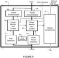
- FIG. 7 illustrates a smart optical transceiver 70, in accordance with one embodiment.
- the smart optical transceiver 70 provides for communication with the power source (e.g., network device 10 in Figure 1 ) during power up of the powered device and may provide fault protection and detection.
- the device 70 is configured to calculate available power and prevent the cabling system from being energized when it should not be powered.
- the optical device 70 includes optical components 72 for receiving optical data and converting it to electrical signals (or converting electrical signals to optical data) and power components including power detection module 74, power monitor and control unit 76, and power enable/disable module 78.
- Pulsed power or advanced PoE driving voltages beyond 60V up to +/-450V may create electromagnetic interference with the optical circuitry 72.
- the power components 74, 76, 78 are isolated from the optical components 72 via an isolation component 79 (e.g., isolation material or element).
- the isolation component 79 electromagnetically isolates the power circuit from the optical components 72 to prevent interference with operation of the optics.
- the power detection module 74 is operable to detect power, energize the optical components 72, and return a message to the power source for fiber or the powered cabling.
- the return message may be provided via state changes on the power wires or over the optical channel.
- the power is not enabled by the power enable/disable module 78 until the optical transceiver 70 and the source have determined that the device is properly connected and the network device to be powered is ready to be powered.
- the power monitor and control device 76 continuously monitors power delivery to ensure that the system can support the needed power delivery, and no safety limits (voltage, current) are exceeded.
- the power monitor and control device 76 may also monitor optical signaling and disable power if there is a lack of optical transitions or communication with the power source.
- FIG 8 illustrates an example of the smart optical transceiver of Figure 7 with auto power negotiation for PoE or pulsed power, in accordance with one embodiment.
- the system 80 includes optical components 82 and power components including power monitor and control 86 and power enable/disable 88.
- the device 80 includes an auto detection module 85 that operates with a pulse power detection module 83 and PoE detection module 84.
- Each module 83, 84 is connected to its own power monitor and control module 86 and power enable; disable module 88.
- the circuit detects the type of power applied to the device 80, determines if PoE or pulsed power is a more efficient power delivery method, and then uses the selected power delivery mode. Additional modes may support other power + data standards (e.g., USB (Universal Serial Bus)).
- USB Universal Serial Bus
- the optical transceiver may comprise different types of optical transceivers, including for example, an optical transceiver module or silicon photonics optical transceiver.
- optical transceiver as used herein may refer to any type of optical component, module, or device operable to receive and transmit optical signals.
- Figures 11A-11B illustrate an example of an optical module configured to contact an electrical interface plate on a modified fiber connector ( Figures 10A-10B ) and pass power through an optical module cage system ( Figures 12A-12B ), as shown in the assembly of Figure 13 . It is to be understood that the optical transceivers shown in Figures 11A and 11B are only examples and that other optical devices configured to receive and transmit power and data may be used to implement PoE+F without departing from the scope of the embodiments.
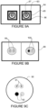
- the connector may comprise, for example, a modified LC (Local Connector, Lucent Connector) generally corresponding to a standard LC format.
- the cable 90 includes two data fibers 91 and two electrical wires 92 (e.g., copper, aluminum, metal) enclosed in a cable jacket.
- the copper wires may be 18 AWG (American Wire Gauge) or another size/capacity (e.g., 10 AWG), or any other suitable size or capacity according to any applicable standard.
- the copper wires 92 may be bonded separately to the optical connector, which allows a modified LC connector system to be implemented without extending a bulkhead connection. As described below, a crimp system may be used to connect the copper wires 91 to the respective plus/minus (plus/return, power/return) connections. It is to be understood that the optical fiber and electrical wire arrangement of the cable 90 shown in Figure 9C is only an example.
- the cable may include any number of optical fibers 91 or electrical wires 92 in any arrangement.
- the cable may include additional data fibers or power wires as described below with respect to a modified MPO (Multi-fiber Push On/Pull Off) connector shown in Figures 16A, 16B, 17A, and 17B.
- the cable may also include cooling as described below with respect to Figure 15 .
- chassis ground is on an outer case 95
- copper (metal) contact 96 for power is on the outside of a ferrule 93
- fiber 97 is inside the ferrule.
- the outer housing 95 is metalized for digital ground and the outer ferrule 96 is metalized for power.
- Data fiber 97 is in ferrule 93, as with conventional LC connectors.
- ground may be connected on one side of the dual connector at the outer ferrule instead of the outer case on both sides of the connector.
- Figures 10A and 10B illustrate details of one example of an LC connector 102 modified to include an external contact plate and a crimp point for which electrical wires can be crimped onto the connector.
- the connector 102 includes a latch mechanism 103 on an upper side that allows the connector to be easily engaged and disengaged.
- the connector 102 mechanically couples and aligns the fibers in ferrule 101 so that light can pass through to the optical transceiver.
- the modified connector 102 receives a cable (e.g., cable 90 shown in Figure 9C ) comprising optical fiber (or fibers) and power wire (or wires).
- the connector 102 further comprises an external metal contact plate (e.g., one or more copper pads) 106 and crimp point 107 onto which the copper wire can be crimped.
- the optical module includes an internal electrical input (e.g., tab or wire contact) for interface with the contact plate 106.
- a portion 108 of the connector body may be extended to allow for the copper wire to be crimped using a standard press-in crimp method.
- the housing 108 is elongated to support 10, 12, 14, 16, or 18 AWG wire systems.
- a spring loaded slide cover 109 may be provided to cover the electrical contact point 106 as the connector is removed from the optical device to prevent energized cable from becoming grounded during handling. The cover 109 is pushed back during insertion of the connector 102 into the optical device, thereby allowing mating contact between the external contact plate 106 and the internal contact point on the optical module when the connector is inserted. If the optical device is not configured to receive power (conventional non-power LC connector), communications compatibility is maintained through the common LC connector interface.
- FIGS 10A and 10B are only an example and that other connectors or configurations may be used without departing from the scope of the embodiments.
- an MPO Multi-fiber Push On/Pull Off
- a single fiber system is shown in Figures 10A and 10B , however, two LC connectors in a duplex fiber system may be used as previously described with respect to Figures 9A and 9B to provide for a power wire and a return wire to interconnect with the optical device.
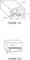
- Figures 11A and11B illustrate an example of an optical module 110 configured to receive power from the modified LC connector 102 of Figure 10B and pass the power through the optical module.
- the optical module 110 includes an opening 111 configured for receiving two connectors 102 at a front end ( Figures 10A and 11A ).
- a rear wall of the opening 111 includes fiber inputs 112.
- the optical module 110 further includes internal electrical input contacts (power tabs, wires, angled spring fingers) 113 for contact with the connector external power pad 106 ( Figures 10B and 11A ).
- the optical device 110 sources power or receives power through these contact points 113.
- the system is configured to handle PoE class 8 systems (up to 100W), as well as other power distribution systems such as pulsed power.
- the optical module 110 may include keying to prevent insertion of certain types of cables into incompatible modules.
- a hook/post arrangement 114 is used to slide the protective cover 109 out of the way to allow for contact between the external contact plate 106 on the connector 102 and the internal electrical power input tab 113 on the optical module 110.
- two female receptacles 116 are provided to connect to the system module cage ( Figure 12B ), along with the electrical signal interface 118 for data and control. If different types of modules are used for PD and PSE interfaces, one may include male pins and the other female sockets. The use of female connectors for power at the rear of the module allows for the module to be accidentally removed under power without damaging anything or anyone.
- the power output points 116 may be located on a lower portion of the optical device 110 as shown in Figure 11B or an upper portion of the device.
- FIGs 12A-12B illustrate an example of an optical module cage 120 for the optical module shown in Figures 11A-11B .
- the optical module cage 120 may include cage ground points 121 and air flow openings 125, for example.
- the cage is modified to include two male power posts 122 (+, return) for mating with the female receptacles 116 on the optical module ( Figures 11B and 12B ).
- the rear wall further includes an opening 128 with contacts for receiving electrical signal interface 118.
- the module cage interface may also include keying to prevent a mismatch between incompatible components.
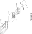
- Figure 13 is an exploded view showing the fiber and power cable 90, connectors 102, optical module 110, and optical module cage 120, in accordance with one embodiment.
- the cable 130 includes two optical fibers 104 and two power wires 105 for connection with the modified LC connector 102 comprising power pads added to a bottom of the connector and a crimping mechanism to allow for attachment of the copper wires 105, as shown in Figure 10B .
- the modified optical module 110 passes through the power received at electrical contact points 113 from the connector 102 to the optical module cage 120, which passes power through to the circuit board (e.g., line card, route processor, fabric card).
- the circuit board e.g., line card, route processor, fabric card
- FIG 14 is a cross-sectional view of a cable design incorporating fiber, power, and cooling.
- a cable 140 includes two data fibers 142, two copper wires 144, and two cooling pipes 146.
- the cooling lines may, for example, deliver water, refrigerant, or high pressure air to the powered device and powered equipment.
- the system may be used to provide cooling to devices and equipment in remote areas where traditional cooling is not available.
- the cable jacket 148 may provide additional insulation, along with insulation on the cooling pipes 146 to provide effective cooling over a 10 km reach, for example.
- FIG. 15 illustrates an example of a connector cable assembly comprising power, fiber, and cooling, in accordance with one embodiment.
- a connector e.g., modified MPO connector
- Press crimp interconnectors may be used to terminate power, ground, and shield, as previously described.
- the example shown in Figure 15 includes two chassis grounds 152, two signal grounds 153, and two optical fibers 155.
- Power 154 may include one connection or two or more pins/mates.
- the cable may also include cooling pipes (e.g., two cooling pipes and two return pipes) (not shown).
- the connector cable assembly may also be configured to include additional fibers (e.g., from two to twenty-four fibers).
- Figure 16 shows another example of a connector 160.
- the optical transceiver 161 is shown with power control circuits 165 and optical to electrical power conversion module 167.
- the connector 160 and optical module 161 are configured for six power fibers 164 and two optical fibers 165 for data.
- power is delivered optically over fibers 164.
- the connector cable assembly shown in Figure 16 may comprise any number or combination of power and optical fibers.
- Figure 17 illustrates the smart optical device of Figure 7 with cooling pass-through lines.
- the optical device 170 includes optical components 172, power detection 174, power monitor and control 176, and power enable/disable 178.
- the optical device 170 may also include additional components shown in Figure 8 , for example.
- the cooling pipes 177 provide cooling to the powered equipment and return cooling.
- a cooling tap 175 is also provided for the optical module 170.
- the optical module cage passes the cooling through to the system and returns the heat generated within the optical components 172 out through the module and into the coolant.
- one or more embodiments may allow for lengths from a building entry point to end points of up to 10 km.
- Network communications devices such as routers, switches, and access points, and electronic devices such as lighting systems and other applications may be located outside of the 100 m range of traditional PoE systems. This allows all electrical power to be removed from floor data rooms.
- Use of a modified connector system allows for fiber compatibility between systems where one or both sides may not be using power over copper delivery to power network equipment.
- the connector assembly may be configured for operation with PoE+F optical systems or conventional non-power optical systems.
Description
- The present disclosure relates generally to communications networks, and more particularly, to power delivery in a communications network.
- Power over Ethernet (PoE) is a technology for providing electrical power over a wired telecommunications network from power sourcing equipment (PSE) to a powered device (PD) over a link section. In conventional PoE systems, power is delivered over the cables used by the data over a range from a few meters to about one hundred meters. When a greater distance is needed or fiber optic cables are used, power must be supplied through a local power source such as a wall outlet due to limitations with conventional PoE. Furthermore, today's PoE systems have limited power capacity, which may be inadequate for many classes of devices.
US 2015/078740 A1 discloses a fiber optic-based communications network including: a power insertion device, connected to multiple fiber links from a data source, configured to provide power insertion to a hybrid fiber/power cable connected to at least one fiber link of the multiple fiber links; the hybrid fiber/power cable, connecting the power insertion device to a connection interface device, configured to transmit data and power from the power insertion device to the connection interface device; and the connection interface device, configured to provide an interface for connection to an end device via a power over Ethernet (PoE)-compatible connection and to provide optical to electrical media conversion for data transmitted from the power insertion device to an end device via the hybrid fiber/power cable and the PoE-compatible connection. -
-
Figure 1 illustrates an example of a network, which does not show the redundancy feature of the independent claims. -
Figure 2 illustrates an example of the network ofFigure 1 with redundant data and power. -
Figure 3 illustrates an example of fog node deployment with the network ofFigure 2 . -
Figure 4 illustrates an example of smart city fog deployment with the network ofFigure 3 . -
Figure 5 is a flowchart illustrating an overview of a process for delivery of power and data in a Power over Ethernet (PoE) + Fiber system, in accordance with one embodiment. -
Figure 6 depicts an example of a network device useful in implementing embodiments described herein. -
Figure 7 is a block diagram of a smart optical module for use in the PoE+F system, in accordance with one embodiment. -
Figure 8 is a block diagram of the smart optical module ofFigure 7 configured for auto power detection, in accordance with one embodiment. -
Figure 9A is a front view of a fiber connector for use in the PoE+F system, in accordance with one embodiment. -
Figure 9B is a front view of the fiber connector, in accordance with another embodiment. -
Figure 9C is a cross-sectional view of a power and data fiber cable for use with the fiber connector, in accordance with one embodiment. -
Figure 10A is a top perspective of the fiber connector, in accordance with one embodiment. -
Figure 10B is a bottom perspective of the fiber connector ofFigure 10A . -
Figure 11A is a front perspective of an optical module for use in the PoE+F system, in accordance with one embodiment. -
Figure 11B is a rear perspective of the optical module ofFigure 11A . -
Figure 12A is a front perspective of an optical module cage for use in the PoE+F system, in accordance with one embodiment. -
Figure 12B is an internal view of a rear wall of the optical module cage ofFigure 12A . -
Figure 13 is an exploded view of the cable, connector, optical module, and optical module cage, in accordance with one embodiment. -
Figure 14 is a cross-sectional view of one example of a cable for use in the PoE+F system. -
Figure 15 is a side view of a connector and cable assembly and optical module for use in the PoE+F system, in accordance with one embodiment. -
Figure 16 is a side view of a connector and cable assembly and optical module, in accordance with another embodiment. -
Figure 17 is a block diagram of the smart optical module ofFigure 7 with cooling, in accordance with one embodiment. - Corresponding reference characters indicate corresponding parts throughout the several views of the drawings.
- Aspects of the invention are set out in the independent claims and preferred features are set out in the dependent claims.
- Further understanding of the features and advantages of the embodiments described herein may be realized by reference to the remaining portions of the specification and the attached drawings.
- The following description is presented to enable one of ordinary skill in the art to make and use the embodiments. For purpose of clarity, details relating to technical material that is known in the technical fields related to the embodiments have not been described in detail.
- In conventional Power over Ethernet (PoE) systems used to simultaneously transmit power and data communications, power is delivered over the same twisted pair cable used for data. These systems are limited in range to a few meters to about 100 meters. Furthermore, the maximum power delivery capacity of standard PoE is approximately 100 Watts, but many classes of powered devices would benefit from power delivery of 1000 Watts or more. When a larger distance is needed, fiber optic cabling is used, or larger power delivery ratings are needed, power needs to be supplied to the device through a local power source.
- The embodiments described herein provide power delivery through an optical transceiver by supplying power integrated with fiber cabling over the same fiber/optical transceiver system so that power may be supplied at greater distances (e.g., up to 10 km), in greater quantity (e.g., up to several kilowatts), and may be provided in locations where local power is difficult to deliver. By incorporating power in the fiber cable and delivering from a building entrance, power does not need to be supplied throughout a data center room and a full zoned system may be deployed without building out a data room. The embodiments effectively deliver communications and power on a large enough scale that equipment in a data room can entirely be powered from an equipment/premise entrance point of the building. Thus, electrical power distribution equipment may be removed from the floor data room and switches, routers, access points, lighting systems, and other electronic devices or equipment may be placed outside of the 100 m range of traditional PoE systems. Through a combination of PoE or pulsed power with a modified optical transceiver and connector system, power can be delivered to equipment in a zone, data room on a floor, or an access point anywhere in the building.
- Internet of Things (IoT) applications like remote sensors / actuators and fog computing can also take advantage of the greater reach and power delivery capacity of this system. With an extended reach (e.g., one to ten km), all power to communications equipment throughout a building or across a neighborhood can be delivered from one source, along with the communications link for the equipment, thereby providing a user with complete control of the location of communications equipment without the 100 m limitation of traditional PoE. As described in detail below, one or more embodiments may be used to deliver power to and from a network (e.g., switch/router) system using an optical transceiver and fiber connector system modified to incorporate electrical wires to deliver power through the optical transceiver and to powered devices. The system is referred to herein as PoE + Fiber (PoE+F).
- Referring now to the drawings, and first to
Figure 1 , an example of a network in which embodiments described herein may be implemented is shown. For simplification, only a small number of nodes are shown. The embodiments operate in the context of a data communications network including multiple network devices. The network may include any number of network devices in communication via any number of nodes (e.g., routers, switches, gateways, controllers, access points, or other network devices), which facilitate passage of data within the network. The network devices may communicate over or be in communication with one or more networks (e.g., local area network (LAN), metropolitan area network (MAN), wide area network (WAN), virtual private network (VPN) (e.g., Ethernet virtual private network (EVPN),layer 2 virtual private network (L2VPN)), virtual local area network (VLAN), wireless network, enterprise network, corporate network, data center, Internet of Things (IoT), Internet, intranet, or any other network). - The network is configured to pass electrical power along with optical data to provide both data connectivity and electric power to network devices such as switches, routers, access points, or other electronic components and devices. Signals may be exchanged among communications equipment and power transmitted from power sourcing equipment to powered devices. As described in detail below, the PoE+F system delivers power to and from a network (e.g., switch/router system) using an optical transceiver (optical module) configured to receive and transmit both data and electrical power, and a cabling system comprising both optical fibers and electrical wires (e.g., copper wires).
- As shown in the example of
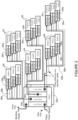
Figure 1 , the PoE+F system uses building power supplied to anetwork device 10, which may be located in a premise/entry room, for example. The power may be transmitted from the building entry point to end points, which may be located at distances greater than 100 meters (e.g., 1 km, 10 km, or any other distance), and/or at greater power levels than 100 Watts (e.g., 250 Watts, 1000 Watts or any other power level). In one or more embodiments, there is no need for additional electrical wiring for the communications network and all of thenetwork communications devices optical transceiver 16 operable to receive and transmit both fiber optics data and power. - The
network device 10 comprises a power supply unit (PSU) 11 for receiving power (e.g., building power), afabric 12, and a plurality ofline cards 13. In the example shown inFigure 1 , one of the line cards receives fiber from outside of the building (e.g., from street or other location) and the other line cards implement PoE+F. Thenetwork device 10 is operable to provide high capacity power from an internal power system (e.g., PSU providing over and including 5 kW (e.g., 10 kW, 12 kW, 14 kW, 16 kW), or PSU providing over and including 100 W (e.g., 500 W, 1 kW) of useable power or any other suitable power capacity). The PSU 11 may provide, for example, PoE, pulsed power, or AC power. As described in detail below, thenetwork device 10 is operable to receive power external from a communications network and transmit the power overdata fiber cables 18 in the communications network (e.g., network comprising central hub 10 (PSE) and a plurality ofnetwork devices 14, 15 (PDs). Thenetwork device 10 may comprise, for example, a router or convergence device (e.g., Network Convergence System (NCS) 4000 series available from Cisco Systems, Inc.) or any other suitable line card system. It is to be understood that this is only an example and any other network device operable to transmit power and optical data may be used. One or more of theline cards 13 may also include anoptical transceiver module 16 operable to transmit power and data on thecables 18. - The network may include any number or arrangement of network communications devices (e.g., switches 14, access points 15, routers, or other devices operable to route (switch, forward) data communications). In one example each group of
access points 15 is located on a different floor or zone. One ormore network devices Figures 3 and4 . For example, one or more of thenetwork devices -
Cables 18 extending from thenetwork device 10 to theswitches 14 andaccess points 15 are configured to transmit power over data fiber cabling and include both optical fibers and electrical wires. In one example, thecables 18 comprise two copper wires and two fibers. Thecables 18 may be formed from any material suitable to carry both electrical power and optical data (e.g., copper, fiber) and may carry any number of electrical wires and optical fibers in any arrangement. As described below with respect toFigures 15 -18, thecables 18 may also include cooling. - The optical transceivers (optical module, optical device, optics module, transceiver, silicon photonics optical transceiver) 16 are configured to source or receive power, as described in detail below. The
transceiver modules 16 operate as an engine that bidirectionally converts optical signals to electrical signals or in general as an interface to the network element copper wire or optical fiber. - In one or more embodiments, the
optical transceiver 16 may be a pluggable transceiver module in any form factor (e.g., SFP (Small Form-Factor Pluggable), QSFP (Quad Small Form-Factor Pluggable), CFP (C Form-Factor Pluggable), and the like), and may support data rates up to 400 Gbps, for example. Hosts for these pluggable optical modules include line cards on theswitches 14, access points 15, or other network devices. One or more of theline cards 13 innetwork device 10 may also host optical modules. The host may include a printed circuit board (PCB) and electronic components and circuits operable to interface telecommunications lines in a telecommunications network. The host may be configured to perform one or more operations and receive any number or type of pluggable transceiver modules configured for transmitting and receiving signals. - The
optical transceiver 16 may also be configured for operation with AOC (Active Optical Cable) and form factors used in UWB (Ultra-Wideband) applications, including for example, Ultra HDMI (High-Definition Multimedia Interface), serial high bandwidth cables (e.g., thunderbolt), and other form factors. - Also, it may be noted that the
optical transceivers 16 may be configured for operation in point-to-multipoint or multipoint-to-point topology. For example, QFSP may breakout to SFP+. One or more embodiments may be configured to allow for load shifting. - As described in detail below, the
optical transceiver 16 is modified along with a fiber connector system to incorporate copper wires to deliver power through the optical transceiver to thepowered devices optical transceiver 16 provides for power to be delivered to theswitches 14 andaccess points 15 in locations where standard power is not available. As described further below, theoptical transceiver 16 may be configured to tap some of the energy and make intelligent decisions so that thepower source 10 knows when it is safe to increase power on the wires without damaging the system or endangering an operator. - In one embodiment, one or more network devices may comprise dual-role power ports that may be selectively configurable to operate as a PSE (Power Source Equipment) port to provide power to a connected device or as a PD (Powered Device) port to sink power from the connected device, and enable the reversal of energy flow under system control, as described in
U.S. Patent No. 9,531,551 ("Dynamically Configurable Power-Over-Ethernet Apparatus and Method", issued December 27, 2016 - In addition to the
network devices optical transceivers 16 operable to receive and transmit power over electrical wires and optical data over fibers, the network may also include one or more network devices comprising conventional optical modules that only process and transmit the optical data. These network devices would receive electrical power from a local power source such as a wall outlet. Similarly, specialized variants oftransceivers 16 could eliminate the optical data interfaces, and only interconnect power (perhaps moving data interconnection to wireless networks). -
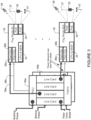
Figure 2 illustrates a redundant data and power PoE+F system. The network includes tworedundant network devices network device data fiber cabling switches 24 and access points 25. Eachswitch 24 andaccess point 25 comprises twooptical transceivers network devices Figure 2 provides backup data and power in the case of failure of anysingle cable network device switches 24 andaccess points 25 may provide power and data to a first circuit and another group of switches and access points may provide power and data to a second circuit. Both circuits may be used to provide power to an equipment power circuit, for example, to provide higher service availability. -
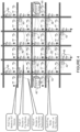
Figure 3 illustrates an example of PoE+F in a fog node deployment, in accordance with one embodiment. Fog is an IoT technique where computation, networking, and storage are moved from the cloud to locations much closer to the IoT sensors and actuators. In the example shown inFigure 3 , power is delivered overdata fiber cables optical transceivers network device data fiber cabling fog nodes 32. In one example, power may be delivered over data fiber cabling to provide approximately 600 W output to each of the twenty-fourfog nodes 32. Eachfog node 32 comprises processing andmemory 33 and one ormore PoE modules 34 operable to power one or more PoE devices. For example, eachfog node 32 may provide approximately 500 W of power to PoE devices such asstreetlights 31,traffic signals 35, 5G cells, access points,base stations 37,video cameras 39, or any other electronic device serving a smart building or smart city. -
Figure 4 illustrates an example of smart city fog deployment, in accordance with one embodiment. In this example, two PoE+Fredundant routers 40 provide primary and backup (redundant) power and data to fognodes 42. Thefog nodes 42 provide power to one or more IoT (Internet of Things) devices 45 (e.g., 5G cells, APs, streetlights, traffic signals, video cameras, or other devices). In one example, each pair ofrouters 40 may serve approximately twenty-fourfog nodes 42, covering approximately 100 city blocks or approximately 1 square km. - The PoE fog node arrangement shown in
Figures 3 and4 may also be used in a smart building (e.g., different fog node for each floor), smart factory (e.g., different fog node for each assembly cell), cruise ship, hotel, school, campus, hospital, shopping center, or any other environment. - It is to be understood that the network devices and topologies shown in
Figures 1 ,2 ,3 , and4 , and described above are only examples and the embodiments described herein may be implemented in networks comprising different network topologies or network devices, without departing from the scope of the embodiments. For example, the network may comprise any number or type of network communications devices that facilitate passage of data over the network (e.g., routers, switches, gateways, controllers), network elements that operate as endpoints or hosts (e.g., servers, virtual machines, clients), and any number of network sites or domains in communication with any number of networks. Thus, network nodes may be used in any suitable network topology, which may include any number of servers, virtual machines, switches, routers, or other nodes interconnected to form a large and complex network, which may include cloud or fog computing. Nodes may be coupled to other nodes or networks through one or more interfaces employing any suitable wired or wireless connection, which provides a viable pathway for electronic communications. -
Figure 5 is a flowchart illustrating an overview of a process for delivering power and data through an optical transceiver system. Atstep 50, power and data are received at anoptical transceiver 16 operating at anetwork device 14, wherein the power is delivered to the optical transceiver overdata fiber cable 18 and received at a connector configured to transmit the power and data from the cable to the optical transceiver (Figure 1 ). Theoptical transceiver 16 transmits power and data to thenetwork device 14, which is powered by the power received at the optical transceiver (step 52) (Figures 1 and5 ). In one or more embodiments, the network device may further transmit PoE to one or more PoE devices (e.g., lights, access points, streetlights, traffic signals, cameras, or other devices) (step 54). - It is to be understood that the process shown in
Figure 5 is only an example of a process for implementing PoE+F and that steps may be added, removed, combined, or modified, without departing from the scope of the embodiments. For example, anoptical transceiver 16 at thecentral hub 10 is operable to transmit power received from thepower supply unit 11 along with data on the power and fiber cable 18 (Figure 1 ). -
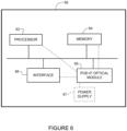
Figure 6 illustrates an example of a network device 60 (e.g., switch 14,access point 15,central hub 10 inFigure 1 ) that may be used to implement the embodiments described herein. In one embodiment, thenetwork device 60 is a programmable machine that may be implemented in hardware, software, or any combination thereof. Thenetwork device 60 includes one ormore processors 62,memory 64,interface 66, and PoE+F optical module 68 (e.g.,optical transceiver 16 inFigure 1 ). -
Memory 64 may be a volatile memory or non-volatile storage, which stores various applications, operating systems, modules, and data for execution and use by theprocessor 62. For example, components of the PoE+F optical module 68 (e.g., code, logic, or firmware, etc.) may be stored in thememory 64. Thenetwork device 60 may include any number of memory components. - The
network device 60 may include any number of processors 62 (e.g., single or multi-processor computing device or system), which may communicate with a forwarding engine or packet forwarder operable to process a packet or packet header. Theprocessor 62 may receive instructions from a software application or module, which causes the processor to perform functions of one or more embodiments described herein. - Logic may be encoded in one or more tangible media for execution by the
processor 62. For example, theprocessor 62 may execute codes stored in a computer-readable medium such asmemory 64. The computer-readable medium may be, for example, electronic (e.g., RAM (random access memory), ROM (read-only memory), EPROM (erasable programmable read-only memory)), magnetic, optical (e.g., CD, DVD), electromagnetic, semiconductor technology, or any other suitable medium. In one example, the computer-readable medium comprises a non-transitory computer-readable medium. Logic may be used to perform one or more functions described above with respect to the flowchart ofFigure 5 or other functions such as power level negotiations or safety subsystems described below. Thenetwork device 60 may include any number ofprocessors 62. - The
interface 66 may comprise any number of interfaces or network interfaces (line cards, ports, connectors) for receiving data or power, or transmitting data or power to other devices. The network interface may be configured to transmit or receive data using a variety of different communications protocols and may include mechanical, electrical, and signaling circuitry for communicating data over physical links coupled to the network or wireless interfaces. For example, line cards may include port processors and port processor controllers. Theinterface 66 may be configured for PoE+F, PoE, PoF, or similar operation. - The PoE+F
optical module 68 may comprise one or more components of theoptical transceiver 16 inFigure 1 and may also include logic, firmware, software, etc. for use with a smart optical module shown inFigures 7 and8 (described below). For example, theoptical module 68 may comprise hardware or software for use in power detection, power monitor and control, or power enable/disable. Theoptical module 68 may further comprise one or more of the processor or memory components, or interface for receiving power and optical data from thecable 18 at a fiber connector, for delivering power and signal data to the network device, or transmitting control signals to thepower source 10, for example (Figures 1 and6 ). As previously described, power is supplied to the optical module bypower supply 67 and the PoE+Foptical module 68 provides power to the rest of the components at thenetwork device 60. - It is to be understood that the
network device 60 shown inFigure 6 and described above is only an example and that different configurations of network devices may be used. For example, thenetwork device 60 may further include any suitable combination of hardware, software, algorithms, processors, devices, components, or elements operable to facilitate the capabilities described herein. -
Figure 7 illustrates a smartoptical transceiver 70, in accordance with one embodiment. The smartoptical transceiver 70 provides for communication with the power source (e.g.,network device 10 inFigure 1 ) during power up of the powered device and may provide fault protection and detection. In one embodiment, thedevice 70 is configured to calculate available power and prevent the cabling system from being energized when it should not be powered. Theoptical device 70 includesoptical components 72 for receiving optical data and converting it to electrical signals (or converting electrical signals to optical data) and power components includingpower detection module 74, power monitor and controlunit 76, and power enable/disablemodule 78. - Pulsed power or advanced PoE driving voltages beyond 60V up to +/-450V, for example, may create electromagnetic interference with the
optical circuitry 72. In one embodiment, thepower components optical components 72 via an isolation component 79 (e.g., isolation material or element). Theisolation component 79 electromagnetically isolates the power circuit from theoptical components 72 to prevent interference with operation of the optics. - The
power detection module 74 is operable to detect power, energize theoptical components 72, and return a message to the power source for fiber or the powered cabling. The return message may be provided via state changes on the power wires or over the optical channel. In one embodiment, the power is not enabled by the power enable/disablemodule 78 until theoptical transceiver 70 and the source have determined that the device is properly connected and the network device to be powered is ready to be powered. - The power monitor and control
device 76 continuously monitors power delivery to ensure that the system can support the needed power delivery, and no safety limits (voltage, current) are exceeded. The power monitor and controldevice 76 may also monitor optical signaling and disable power if there is a lack of optical transitions or communication with the power source. -
Figure 8 illustrates an example of the smart optical transceiver ofFigure 7 with auto power negotiation for PoE or pulsed power, in accordance with one embodiment. As previously described thesystem 80 includesoptical components 82 and power components including power monitor andcontrol 86 and power enable/disable 88. In the example shown inFigure 8 , thedevice 80 includes anauto detection module 85 that operates with a pulsepower detection module 83 andPoE detection module 84. Eachmodule control module 86 and power enable; disablemodule 88. The circuit detects the type of power applied to thedevice 80, determines if PoE or pulsed power is a more efficient power delivery method, and then uses the selected power delivery mode. Additional modes may support other power + data standards (e.g., USB (Universal Serial Bus)). - As previously described, the optical transceiver may comprise different types of optical transceivers, including for example, an optical transceiver module or silicon photonics optical transceiver. The term "optical transceiver" as used herein may refer to any type of optical component, module, or device operable to receive and transmit optical signals.
Figures 11A-11B illustrate an example of an optical module configured to contact an electrical interface plate on a modified fiber connector (Figures 10A-10B ) and pass power through an optical module cage system (Figures 12A-12B ), as shown in the assembly ofFigure 13 . It is to be understood that the optical transceivers shown inFigures 11A and 11B are only examples and that other optical devices configured to receive and transmit power and data may be used to implement PoE+F without departing from the scope of the embodiments. - Referring now to
Figures 9A and 9B , two examples of a modified fiber connector are shown for receiving power and fiber from acable 90 comprising optical fibers and electrical wires, as shown inFigure 9C . The connector may comprise, for example, a modified LC (Local Connector, Lucent Connector) generally corresponding to a standard LC format. In the example shown inFigure 9C , thecable 90 includes twodata fibers 91 and two electrical wires 92 (e.g., copper, aluminum, metal) enclosed in a cable jacket. - In one example, the copper wires may be 18 AWG (American Wire Gauge) or another size/capacity (e.g., 10 AWG), or any other suitable size or capacity according to any applicable standard. The
copper wires 92 may be bonded separately to the optical connector, which allows a modified LC connector system to be implemented without extending a bulkhead connection. As described below, a crimp system may be used to connect thecopper wires 91 to the respective plus/minus (plus/return, power/return) connections. It is to be understood that the optical fiber and electrical wire arrangement of thecable 90 shown inFigure 9C is only an example. The cable may include any number ofoptical fibers 91 orelectrical wires 92 in any arrangement. For example, the cable may include additional data fibers or power wires as described below with respect to a modified MPO (Multi-fiber Push On/Pull Off) connector shown in Figures 16A, 16B, 17A, and 17B. The cable may also include cooling as described below with respect toFigure 15 . - In the
connector 94 shown in the example ofFigure 9A , chassis ground is on anouter case 95, copper (metal)contact 96 for power is on the outside of aferrule 93, andfiber 97 is inside the ferrule. In this example, theouter housing 95 is metalized for digital ground and theouter ferrule 96 is metalized for power.Data fiber 97 is inferrule 93, as with conventional LC connectors. In another example, ground may be connected on one side of the dual connector at the outer ferrule instead of the outer case on both sides of the connector. - In another
dual LC connector 98 example shown inFigure 9B , one side of a connector contains twofibers 99 and the other side of the connector containspower wires 100. It is to be understood that the configurations shown inFigures 9A and 9B are only examples and that other arrangements may be used without departing from the scope of the embodiments. -
Figures 10A and 10B illustrate details of one example of anLC connector 102 modified to include an external contact plate and a crimp point for which electrical wires can be crimped onto the connector. As with conventional LC connectors, theconnector 102 includes alatch mechanism 103 on an upper side that allows the connector to be easily engaged and disengaged. Theconnector 102 mechanically couples and aligns the fibers inferrule 101 so that light can pass through to the optical transceiver. The modifiedconnector 102 receives a cable (e.g.,cable 90 shown inFigure 9C ) comprising optical fiber (or fibers) and power wire (or wires). As shown in the bottom view ofFigure 10B , theconnector 102 further comprises an external metal contact plate (e.g., one or more copper pads) 106 and crimppoint 107 onto which the copper wire can be crimped. As described below with respect toFigure 11A , the optical module includes an internal electrical input (e.g., tab or wire contact) for interface with thecontact plate 106. Aportion 108 of the connector body may be extended to allow for the copper wire to be crimped using a standard press-in crimp method. In one embodiment, thehousing 108 is elongated to support 10, 12, 14, 16, or 18 AWG wire systems. - In one or more embodiments, a spring loaded slide cover 109 (shown partially open in
Figure 10B ) may be provided to cover theelectrical contact point 106 as the connector is removed from the optical device to prevent energized cable from becoming grounded during handling. Thecover 109 is pushed back during insertion of theconnector 102 into the optical device, thereby allowing mating contact between theexternal contact plate 106 and the internal contact point on the optical module when the connector is inserted. If the optical device is not configured to receive power (conventional non-power LC connector), communications compatibility is maintained through the common LC connector interface. - It is to be understood that the connector shown in
Figures 10A and 10B is only an example and that other connectors or configurations may be used without departing from the scope of the embodiments. For example, in one embodiment, an MPO (Multi-fiber Push On/Pull Off) coupling may be used. Also, a single fiber system is shown inFigures 10A and 10B , however, two LC connectors in a duplex fiber system may be used as previously described with respect toFigures 9A and 9B to provide for a power wire and a return wire to interconnect with the optical device. -
Figures 11A and11B illustrate an example of anoptical module 110 configured to receive power from the modifiedLC connector 102 ofFigure 10B and pass the power through the optical module. Theoptical module 110 includes anopening 111 configured for receiving twoconnectors 102 at a front end (Figures 10A and11A ). A rear wall of theopening 111 includesfiber inputs 112. Theoptical module 110 further includes internal electrical input contacts (power tabs, wires, angled spring fingers) 113 for contact with the connector external power pad 106 (Figures 10B and11A ). Theoptical device 110 sources power or receives power through these contact points 113. In one example, the system is configured to handle PoE class 8 systems (up to 100W), as well as other power distribution systems such as pulsed power. In one embodiment, theoptical module 110 may include keying to prevent insertion of certain types of cables into incompatible modules. - In one embodiment, a hook/
post arrangement 114 is used to slide theprotective cover 109 out of the way to allow for contact between theexternal contact plate 106 on theconnector 102 and the internal electricalpower input tab 113 on theoptical module 110. - As shown in the rear view of
Figure 11B , twofemale receptacles 116 are provided to connect to the system module cage (Figure 12B ), along with theelectrical signal interface 118 for data and control. If different types of modules are used for PD and PSE interfaces, one may include male pins and the other female sockets. The use of female connectors for power at the rear of the module allows for the module to be accidentally removed under power without damaging anything or anyone. The power output points 116 may be located on a lower portion of theoptical device 110 as shown inFigure 11B or an upper portion of the device. -
Figures 12A-12B illustrate an example of anoptical module cage 120 for the optical module shown inFigures 11A-11B . Theoptical module cage 120 may include cage ground points 121 andair flow openings 125, for example. As shown on the internalrear wall 126 of the module cage inFigure 12B , the cage is modified to include two male power posts 122 (+, return) for mating with thefemale receptacles 116 on the optical module (Figures 11B and12B ). The rear wall further includes anopening 128 with contacts for receivingelectrical signal interface 118. As previously described with respect to the optical module, the module cage interface may also include keying to prevent a mismatch between incompatible components. -
Figure 13 is an exploded view showing the fiber andpower cable 90,connectors 102,optical module 110, andoptical module cage 120, in accordance with one embodiment. In this example, the cable 130 includes twooptical fibers 104 and twopower wires 105 for connection with the modifiedLC connector 102 comprising power pads added to a bottom of the connector and a crimping mechanism to allow for attachment of thecopper wires 105, as shown inFigure 10B . The modifiedoptical module 110 passes through the power received at electrical contact points 113 from theconnector 102 to theoptical module cage 120, which passes power through to the circuit board (e.g., line card, route processor, fabric card). - As previously noted, the power and fiber cable may also include cooling.
Figure 14 is a cross-sectional view of a cable design incorporating fiber, power, and cooling. In this example, acable 140 includes twodata fibers 142, twocopper wires 144, and two coolingpipes 146. The cooling lines may, for example, deliver water, refrigerant, or high pressure air to the powered device and powered equipment. The system may be used to provide cooling to devices and equipment in remote areas where traditional cooling is not available. Thecable jacket 148 may provide additional insulation, along with insulation on the coolingpipes 146 to provide effective cooling over a 10 km reach, for example. -
Figure 15 illustrates an example of a connector cable assembly comprising power, fiber, and cooling, in accordance with one embodiment. A connector (e.g., modified MPO connector) 150 provides power and data tooptical transceiver 151. Press crimp interconnectors may be used to terminate power, ground, and shield, as previously described. The example shown inFigure 15 includes twochassis grounds 152, twosignal grounds 153, and twooptical fibers 155. Power 154 may include one connection or two or more pins/mates. The cable may also include cooling pipes (e.g., two cooling pipes and two return pipes) (not shown). The connector cable assembly may also be configured to include additional fibers (e.g., from two to twenty-four fibers). -
Figure 16 shows another example of aconnector 160. Theoptical transceiver 161 is shown withpower control circuits 165 and optical to electricalpower conversion module 167. In this example, theconnector 160 andoptical module 161 are configured for sixpower fibers 164 and twooptical fibers 165 for data. In this example, power is delivered optically overfibers 164. The connector cable assembly shown inFigure 16 may comprise any number or combination of power and optical fibers. - It is to be understood that the configuration, arrangement, and number of power/ground wires and fibers shown in
Figures 15 and16 are only examples and that other arrangements or number of wires and fibers may be used without departing from the scope of the embodiments. -
Figure 17 illustrates the smart optical device ofFigure 7 with cooling pass-through lines. As previously described, theoptical device 170 includesoptical components 172,power detection 174, power monitor andcontrol 176, and power enable/disable 178. Theoptical device 170 may also include additional components shown inFigure 8 , for example. The coolingpipes 177 provide cooling to the powered equipment and return cooling. Acooling tap 175 is also provided for theoptical module 170. In one embodiment, the optical module cage passes the cooling through to the system and returns the heat generated within theoptical components 172 out through the module and into the coolant. - As can be observed from the foregoing, the embodiments described herein may provide many advantages. For example, one or more embodiments may allow for lengths from a building entry point to end points of up to 10 km. Network communications devices such as routers, switches, and access points, and electronic devices such as lighting systems and other applications may be located outside of the 100 m range of traditional PoE systems. This allows all electrical power to be removed from floor data rooms. Use of a modified connector system allows for fiber compatibility between systems where one or both sides may not be using power over copper delivery to power network equipment. For example, the connector assembly may be configured for operation with PoE+F optical systems or conventional non-power optical systems.
- The scope of the invention is defined by the appended independent claims. Accordingly, it is intended that all matter contained in the above description and shown in the accompanying drawings shall be interpreted as illustrative and not in a limiting sense.
Claims (15)
- A method comprising:receiving power delivered over a data fiber cable (28a) at a first optical transceiver (26a) installed at a network communications device; andtransmitting data and the power from the first optical transceiver (26a) to the network communications device;wherein the network communications device is powered by the power received from the first optical transceiver (26a);characterized by further comprising receiving redundant data and power at a second optical transceiver (26b) installed at the network communications device.
- The method of claim 1 wherein the data fiber cable (28a, 28b) extends between the network device and a power supply unit (20a, 20b) and the data and the power are received via the data fiber cable (28a, 28b) from the power supply unit (20a, 20b) located at least 1 km from the network communications device, and optionally wherein the power supply unit (20a, 20b) is operable to provide a power output of at least 5 kW.
- The method of any of claims 1 to 2 further comprising transmitting Power over Ethernet, PoE, from the network communications device to a PoE device.
- The method of claim 3 wherein the network communications device comprises a fog node (32) receiving the data and the power along with a plurality of fog nodes, each of the fog nodes (42) transmitting said PoE to a plurality of electronic devices in a smart fog deployment.
- The method of any of claims 1 to 4 wherein the optical transceiver comprises an optical module receiving the data and the power from a fiber connector comprising an external electrical contact (106) for providing the power to a corresponding internal electrical power input (113) in the optical module, and optionally wherein the fiber connector comprises a crimp point (107) for crimping the wires (105) delivering the power to the optical transceiver (26a, 26b) onto the fiber connector delivering the data and the power to the optical transceiver (26a, 26b).
- The method of any of claims 1 to 5 further comprising communicating at the network communications device with a power source and providing a power status at the optical transceiver (26a, 26b), and/or wherein the optical transceiver (26a, 26b) is configured to monitor the power and optical signals at the optical transceiver and disable the power based on a status of the power and the optical signals.
- The method of any of claims 1 to 6 wherein power components are isolated from optical components in the optical transceiver (26a, 26b).
- The method of any of claims 1 to 7 further comprising receiving cooling at the optical transceiver via cooling pipes included in the data fiber cable (28a).
- The method of any of claims 1 to 8 further comprising detecting a type of power received at the optical transceiver (26a, 26b) and selecting a delivery method for the power based on the detected type of power.
- The method of any of claims 1 to 9 wherein the network communications device comprises a switch (24) and wherein a plurality of switches in a data communications network are powered from a same power source over the data fiber cable.
- A network communications device comprising:a first optical interface for receiving optical signals on an optical fiber in a fiber and power cable at a first optical transceiver (26a);a first electrical interface for receiving power on an electrical wire in the fiber and power cable at the first optical transceiver (26a);an optical component (72) for converting the optical signals to electrical signals; anda power component (74, 76, 78) for detecting and monitoring the power at the optical transceiver (26a) and providing the power to the network communications device;characterized by a second optical interface for receiving redundant optical signals on an optical fiber in a fiber and power cable at a second transceiver (20b); anda second electrical interface for receiving redundant power on an electrical wire in the fiber and power cable at a second transceiver (20b).
- The network communications device of claim 11 wherein the optical transceiver is configured to monitor the optical signals at the optical transceiver (26a, 26b) and disable the power based on a status of the power and the optical signals.
- The network communications device of claim 11 or 12 wherein the optical transceiver (26a, 26b) is configured to detect a type of power received at the optical transceiver and select a delivery method for the power to the network communications device based on the detected type of power.
- A system comprising:
a network communications device according to claim 11 further comprising:a first power supply unit (20a) for receiving power external from a communications network and providing the power to the first optical transceiver (26a) for transmission in the communications network; anda second power supply unit (20b) for receiving redundant power external from a communications network and providing the power to the second optical transceiver (26b) for transmission in the communications network. - The system of claim 14 wherein at least one of the power supply units (20a, 20b) is operable to provide a power output of at least 5 kW, and optionally further comprising a power module for receiving power information from powered devices.
Priority Applications (1)
| Application Number | Priority Date | Filing Date | Title |
|---|---|---|---|
| EP24160388.5A EP4354805A2 (en) | 2017-09-18 | 2018-09-07 | Power delivery through an optical system |
Applications Claiming Priority (2)
| Application Number | Priority Date | Filing Date | Title |
|---|---|---|---|
| US15/707,976 US10541758B2 (en) | 2017-09-18 | 2017-09-18 | Power delivery through an optical system |
| PCT/US2018/050055 WO2019055318A1 (en) | 2017-09-18 | 2018-09-07 | Power delivery through an optical system |
Related Child Applications (1)
| Application Number | Title | Priority Date | Filing Date |
|---|---|---|---|
| EP24160388.5A Division EP4354805A2 (en) | 2017-09-18 | 2018-09-07 | Power delivery through an optical system |
Publications (2)
| Publication Number | Publication Date |
|---|---|
| EP3685547A1 EP3685547A1 (en) | 2020-07-29 |
| EP3685547B1 true EP3685547B1 (en) | 2024-03-06 |
Family
ID=63720764
Family Applications (2)
| Application Number | Title | Priority Date | Filing Date |
|---|---|---|---|
| EP24160388.5A Pending EP4354805A2 (en) | 2017-09-18 | 2018-09-07 | Power delivery through an optical system |
| EP18780270.7A Active EP3685547B1 (en) | 2017-09-18 | 2018-09-07 | Power delivery through an optical system |
Family Applications Before (1)
| Application Number | Title | Priority Date | Filing Date |
|---|---|---|---|
| EP24160388.5A Pending EP4354805A2 (en) | 2017-09-18 | 2018-09-07 | Power delivery through an optical system |
Country Status (5)
| Country | Link |
|---|---|
| US (4) | US10541758B2 (en) |
| EP (2) | EP4354805A2 (en) |
| JP (1) | JP7281455B2 (en) |
| CN (1) | CN111095866B (en) |
| WO (1) | WO2019055318A1 (en) |
Families Citing this family (35)
| Publication number | Priority date | Publication date | Assignee | Title |
|---|---|---|---|---|
| US10809134B2 (en) | 2017-05-24 | 2020-10-20 | Cisco Technology, Inc. | Thermal modeling for cables transmitting data and power |
| US11054457B2 (en) | 2017-05-24 | 2021-07-06 | Cisco Technology, Inc. | Safety monitoring for cables transmitting data and power |
| US10541758B2 (en) | 2017-09-18 | 2020-01-21 | Cisco Technology, Inc. | Power delivery through an optical system |
| US11431420B2 (en) | 2017-09-18 | 2022-08-30 | Cisco Technology, Inc. | Power delivery through an optical system |
| MX2018013888A (en) * | 2017-11-13 | 2019-06-06 | Ortronics Inc | Hybridized cable assembly. |
| US11093012B2 (en) | 2018-03-02 | 2021-08-17 | Cisco Technology, Inc. | Combined power, data, and cooling delivery in a communications network |
| US10281513B1 (en) | 2018-03-09 | 2019-05-07 | Cisco Technology, Inc. | Verification of cable application and reduced load cable removal in power over communications systems |
| US10770203B2 (en) | 2018-07-19 | 2020-09-08 | Commscope Technologies Llc | Plug-in power and data connectivity micro grids for information and communication technology infrastructure and related methods of deploying such micro grids |
| US10790997B2 (en) | 2019-01-23 | 2020-09-29 | Cisco Technology, Inc. | Transmission of pulse power and data in a communications network |
| US11061456B2 (en) | 2019-01-23 | 2021-07-13 | Cisco Technology, Inc. | Transmission of pulse power and data over a wire pair |
| US10680836B1 (en) | 2019-02-25 | 2020-06-09 | Cisco Technology, Inc. | Virtualized chassis with power-over-Ethernet for networking applications |
| US11456883B2 (en) | 2019-03-13 | 2022-09-27 | Cisco Technology, Inc. | Multiple phase pulse power in a network communications system |
| CN113632323A (en) * | 2019-04-12 | 2021-11-09 | 3M创新有限公司 | High density connector assembly |
| CN113544936B (en) * | 2019-07-22 | 2022-07-08 | 京瓷株式会社 | Optical power supply system |
| GB201911072D0 (en) * | 2019-08-02 | 2019-09-18 | Esc Digital Media Ltd | Wireless phone charger with power over ethernet |
| US11063630B2 (en) | 2019-11-01 | 2021-07-13 | Cisco Technology, Inc. | Initialization and synchronization for pulse power in a network system |
| CN113097761B (en) * | 2020-01-08 | 2022-05-31 | 华为技术有限公司 | Photoelectric connecting device |
| US11252811B2 (en) | 2020-01-15 | 2022-02-15 | Cisco Technology, Inc. | Power distribution from point-of-load with cooling |
| US11853138B2 (en) | 2020-01-17 | 2023-12-26 | Cisco Technology, Inc. | Modular power controller |
| US11438183B2 (en) | 2020-02-25 | 2022-09-06 | Cisco Technology, Inc. | Power adapter for power supply unit |
| US11543844B2 (en) | 2020-02-25 | 2023-01-03 | Cisco Technology, Inc. | Method and apparatus for transmitting power and data in a multi-drop architecture |
| US11637497B2 (en) | 2020-02-28 | 2023-04-25 | Cisco Technology, Inc. | Multi-phase pulse power short reach distribution |
| US11307368B2 (en) | 2020-04-07 | 2022-04-19 | Cisco Technology, Inc. | Integration of power and optics through cold plates for delivery to electronic and photonic integrated circuits |
| US11320610B2 (en) | 2020-04-07 | 2022-05-03 | Cisco Technology, Inc. | Integration of power and optics through cold plate for delivery to electronic and photonic integrated circuits |
| US11915276B2 (en) | 2020-04-28 | 2024-02-27 | Cisco Technology, Inc. | System, method, and computer readable storage media for millimeter wave radar detection of physical actions coupled with an access point off-load control center |
| US11582048B2 (en) | 2020-07-17 | 2023-02-14 | Cisco Technology, Inc. | Bi-directional power over ethernet for digital building applications |
| US11708002B2 (en) | 2020-08-03 | 2023-07-25 | Cisco Technology, Inc. | Power distribution and communications for electric vehicle |
| RU201461U1 (en) * | 2020-08-14 | 2020-12-16 | Общество с ограниченной ответственностью "Научно-Производственный Центр Профотек", | OPTICAL RADIATION ELECTRIC SUPPLY DEVICE |
| US11745613B2 (en) | 2020-08-26 | 2023-09-05 | Cisco Technology, Inc. | System and method for electric vehicle charging and security |
| US11482351B2 (en) * | 2020-09-29 | 2022-10-25 | Hewlett Packard Enterprise Development Lp | Pluggable network interface port with powering for remote device |
| CN114500124A (en) * | 2020-11-12 | 2022-05-13 | 华为技术有限公司 | PoE power supply equipment, PoE power supply system and interface component |
| CN112751619B (en) * | 2020-12-31 | 2022-04-05 | 武汉光迅科技股份有限公司 | Photoelectric composite optical module |
| US11435801B1 (en) * | 2021-03-17 | 2022-09-06 | Dell Products L.P. | Powering co-packaged networking system |
| CN117075272A (en) * | 2022-05-10 | 2023-11-17 | 中兴通讯股份有限公司 | Optical module and optical signal system |
| US20230412265A1 (en) * | 2022-06-14 | 2023-12-21 | Mellanox Technologies, Ltd. | Transceiver module |
Citations (4)
| Publication number | Priority date | Publication date | Assignee | Title |
|---|---|---|---|---|
| EP3759869A1 (en) * | 2018-03-02 | 2021-01-06 | Cisco Technology, Inc. | Combined power, data, and cooling delivery in a communications network |
| EP3766208A1 (en) * | 2018-03-12 | 2021-01-20 | Cisco Technology, Inc. | Splitting of combined delivery power, data, and cooling in a communications network |
| EP3777051A1 (en) * | 2018-03-30 | 2021-02-17 | Cisco Technology, Inc. | Interface module for combined delivery power, data, and cooling at a network device |
| EP3788743A1 (en) * | 2018-05-04 | 2021-03-10 | Cisco Technology, Inc. | High power and data delivery in a communications network with safety and fault protection |
Family Cites Families (224)
| Publication number | Priority date | Publication date | Assignee | Title |
|---|---|---|---|---|
| US3335324A (en) | 1965-10-06 | 1967-08-08 | Westinghouse Air Brake Co | Fail-safe continuous ground monitoring circuit |
| EP0191482B1 (en) | 1985-02-12 | 1990-07-25 | Hitachi Metals, Ltd. | Dc-dc converter |
| JPS62232608A (en) * | 1986-03-31 | 1987-10-13 | アンプ インコ−ポレ−テツド | Optoelectronic compound type connector |
| EP0517346B1 (en) * | 1985-12-26 | 1996-05-01 | The Whitaker Corporation | Optical fiber connector |
| US5827267A (en) * | 1992-02-18 | 1998-10-27 | Angeion Corporation | Cooled multi-fiber medical connector |
| US5652893A (en) | 1994-12-13 | 1997-07-29 | 3Com Corporation | Switching hub intelligent power management |
| US6470405B2 (en) | 1995-10-19 | 2002-10-22 | Rambus Inc. | Protocol for communication with dynamic memory |
| US6931183B2 (en) | 1996-03-29 | 2005-08-16 | Dominion Lasercom, Inc. | Hybrid electro-optic cable for free space laser antennas |
| US7237036B2 (en) | 1997-10-14 | 2007-06-26 | Alacritech, Inc. | Fast-path apparatus for receiving data corresponding a TCP connection |
| US6220955B1 (en) | 1998-02-17 | 2001-04-24 | John G. Posa | Combination power and cooling cable |
| US6826368B1 (en) * | 1998-10-20 | 2004-11-30 | Lucent Technologies Inc. | Wavelength division multiplexing (WDM) with multi-frequency lasers and optical couplers |
| WO2000027079A1 (en) | 1998-10-30 | 2000-05-11 | Broadcom Corporation | Internet gigabit ethernet transmitter architecture |
| US6643566B1 (en) | 1999-01-12 | 2003-11-04 | Powerdsine Ltd. | System for power delivery over data communication cabling infrastructure |
| US6008631A (en) | 1999-03-18 | 1999-12-28 | International Business Machines Corporation | Synchronous voltage converter |
| US6636538B1 (en) | 1999-03-29 | 2003-10-21 | Cutting Edge Optronics, Inc. | Laser diode packaging |
| US20030214800A1 (en) | 1999-07-15 | 2003-11-20 | Dibene Joseph Ted | System and method for processor power delivery and thermal management |
| JP2001177031A (en) | 1999-12-15 | 2001-06-29 | Hitachi Ltd | Optical transmitter-receiver having cooling device |
| US6400579B2 (en) | 2000-03-24 | 2002-06-04 | Slobodan Cuk | Lossless switching DC to DC converter with DC transformer |
| JP3830726B2 (en) | 2000-04-26 | 2006-10-11 | 松下電器産業株式会社 | Thermally conductive substrate, manufacturing method thereof, and power module |
| US6734784B1 (en) | 2000-09-06 | 2004-05-11 | Marshall E. Lester | Zero crossing based powerline pulse position modulated communication system |
| USRE40866E1 (en) | 2000-09-27 | 2009-08-04 | Huron Ip Llc | System, method, and architecture for dynamic server power management and dynamic workload management for multiserver environment |
| CN1209880C (en) | 2001-11-30 | 2005-07-06 | 王德清 | Wideband access transmission entwork as assembly of power supply, telecommunication device, TV set and internet network |
| US6685364B1 (en) * | 2001-12-05 | 2004-02-03 | International Business Machines Corporation | Enhanced folded flexible cable packaging for use in optical transceivers |
| US7358745B1 (en) | 2002-06-07 | 2008-04-15 | Marvell International Ltd. | Cable tester |
| US6855881B2 (en) | 2002-06-26 | 2005-02-15 | Bahman Khoshnood | Combined communication and power cable with air cooling for network systems |
| US7254332B2 (en) * | 2002-08-06 | 2007-08-07 | Jun-Kook Choi | Wavelength division multiplexing passive optical network system |
| US6851960B2 (en) | 2002-08-29 | 2005-02-08 | Dell Products L.P. | AC adapter connector assembly |
| WO2004104641A2 (en) | 2003-05-08 | 2004-12-02 | Sioptical, Inc. | High speed, silicon-based electro-optic modulator |
| US6989997B2 (en) | 2003-06-25 | 2006-01-24 | Virginia Tech Intellectual Properties, Inc. | Quasi-resonant DC-DC converters with reduced body diode loss |
| US7492059B2 (en) | 2003-10-16 | 2009-02-17 | Microsemi Corp.—Analog Mixed Signal Group Ltd. | High power architecture for power over ethernet |
| US7583703B2 (en) | 2003-10-23 | 2009-09-01 | Cisco Technology Inc. | System and method for power injection and out of band communications on shared medium |
| US6976885B2 (en) | 2004-03-02 | 2005-12-20 | Mobility Electronics, Inc. | Keyed universal power tip and power source connectors |
| US7212419B2 (en) | 2004-02-24 | 2007-05-01 | Vlt, Inc. | Adaptively configured and autoranging voltage transformation module arrays |
| JP2005316475A (en) * | 2004-04-29 | 2005-11-10 | Sumitomo Electric Ind Ltd | Optical transceiver |
| US7603570B2 (en) | 2004-05-13 | 2009-10-13 | Cisco Technology, Inc. | Power delivery over ethernet cables |
| CN100544131C (en) | 2004-06-24 | 2009-09-23 | 摩勒克斯公司 | Jack connector assembly with integrated circuit component that the POE function is provided |
| US7056149B1 (en) | 2004-11-12 | 2006-06-06 | Comarco Wireless Technologies, Inc. | Key coded power adapter connectors |
| US7509505B2 (en) | 2005-01-04 | 2009-03-24 | Cisco Technology, Inc. | Method and system for managing power delivery for power over Ethernet systems |
| US8543008B2 (en) * | 2005-03-01 | 2013-09-24 | Alexander I Soto | System and method for a subscriber powered network element |
| US7263245B2 (en) | 2005-03-14 | 2007-08-28 | The Boeing Company | Method and apparatus for optically powering and multiplexing distributed fiber optic sensors |
| US7474704B2 (en) | 2005-03-16 | 2009-01-06 | Cisco Technology, Inc. | Method and apparatus for current sharing ethernet power across four conductor pairs |
| US8184525B2 (en) | 2005-05-25 | 2012-05-22 | Cisco Technology, Inc. | Method and apparatus for detecting and fixing faults in an inline-power capable ethernet system |
| US7586840B2 (en) | 2005-05-25 | 2009-09-08 | Cisco Technology, Inc. | Method and apparatus for detecting and fixing faults in an inline-power capable ethernet system |
| US7593747B1 (en) | 2005-07-01 | 2009-09-22 | Cisco Technology, Inc. | Techniques for controlling delivery of power to a remotely powerable device based on temperature |
| US9189036B2 (en) | 2005-08-19 | 2015-11-17 | Akros Silicon, Inc. | Ethernet module |
| US7940787B2 (en) | 2005-08-30 | 2011-05-10 | Cisco Technology, Inc. | Low-power ethernet device |
| US7265555B2 (en) | 2005-11-09 | 2007-09-04 | Douglas William Batten | Loop impedance meter |
| US8432142B2 (en) | 2006-01-17 | 2013-04-30 | Broadcom Corporation | Power over ethernet controller integrated circuit architecture |
| US7560825B2 (en) | 2006-04-11 | 2009-07-14 | Akros Silicon, Inc. | Network devices for separating power and data signals |
| US7490251B2 (en) | 2006-04-13 | 2009-02-10 | Cisco Technology, Inc. | Method and apparatus for current sharing ethernet power across four conductor pairs using a midspan device |
| US20070288771A1 (en) | 2006-06-08 | 2007-12-13 | Steven Andrew Robbins | Source Separator for Power over Ethernet Systems |
| US20070284941A1 (en) | 2006-06-08 | 2007-12-13 | Steven Andrew Robbins | Power Cross-Coupler for Power over Ethernet |
| US20070288125A1 (en) | 2006-06-09 | 2007-12-13 | Mks Instruments, Inc. | Power Over Ethernet (Poe) - Based Measurement System |
| US20070284946A1 (en) | 2006-06-10 | 2007-12-13 | Steven Andrew Robbins | Passive Power Combiner for Dual Power over Ethernet Sources |
| US7835389B2 (en) | 2006-09-20 | 2010-11-16 | Broadcom Corporation | Method and system for an extended range Ethernet line code using 4B/3B mapping |
| US9515843B2 (en) | 2006-06-22 | 2016-12-06 | Broadcom Corporation | Method and system for link adaptive Ethernet communications |
| US7420355B2 (en) | 2006-07-11 | 2008-09-02 | Artesyn Technologies, Inc. | DC-DC converter with over-voltage protection |
| US7589435B2 (en) | 2006-08-02 | 2009-09-15 | Cisco Technology, Inc. | Reporting power requirements of a powered device |
| US7490996B2 (en) | 2006-08-16 | 2009-02-17 | Sigmund Sommer | Electro-optical plug and receptacle |
| US20080063399A1 (en) | 2006-09-13 | 2008-03-13 | Mallya Arvind R | Methods and apparatus to implement communication networks using electrically conductive and optical communication media |
| US7566987B2 (en) | 2006-09-14 | 2009-07-28 | Lutron Electronics Co., Inc. | Method of powering up a plurality of loads in sequence |
| US7915761B1 (en) | 2006-09-27 | 2011-03-29 | Cisco Technology, Inc. | Power injector detection |
| US7664972B2 (en) | 2006-12-19 | 2010-02-16 | Broadcom Corporation | System and method for controlling power delivered to a powered device based on cable characteristics |
| US20080198635A1 (en) | 2007-02-21 | 2008-08-21 | Broadcom Corporation | Pulse width modulated ground/return for powered device |
| US7814346B2 (en) | 2007-03-12 | 2010-10-12 | Broadcom Corporation | System and method for continual cable thermal monitoring using cable resistance considerations in power over ethernet |
| CN101680718A (en) | 2007-03-14 | 2010-03-24 | 佐尼特结构解决方案有限责任公司 | Air-based cooling for data center rack |
| US8037324B2 (en) | 2007-03-20 | 2011-10-11 | Broadcom Corporation | Power over ethernet connector with integrated power source equipment (PSE) controller supporting high power applications |
| US7921307B2 (en) | 2007-03-27 | 2011-04-05 | Cisco Technology, Inc. | Methods and apparatus providing advanced classification for power over Ethernet |
| US20080276104A1 (en) | 2007-05-01 | 2008-11-06 | Broadcom Corporation | Power source equiment for power over ethernet system with increased cable length |
| DE202007007927U1 (en) | 2007-06-05 | 2007-08-23 | Bürkert Werke GmbH & Co. KG | Hybrid universal distribution system with electrical, fluidic and communication functions |
| US7737704B2 (en) | 2007-06-12 | 2010-06-15 | Broadcom Corporation | System and method for using a PHY to locate a thermal signature in a cable plant for diagnostic, enhanced, and higher power applications |
| US8094452B1 (en) | 2007-06-27 | 2012-01-10 | Exaflop Llc | Cooling and power grids for data center |
| US7813646B2 (en) | 2007-07-11 | 2010-10-12 | RLH Industries, Inc | Power over optical fiber system |
| US7797560B2 (en) | 2007-07-24 | 2010-09-14 | Broadcom Corporation | System and method for integrated temperature measurement in power over Ethernet applications |
| US8081589B1 (en) | 2007-08-28 | 2011-12-20 | Meru Networks | Access points using power over ethernet |
| JP2009058547A (en) | 2007-08-30 | 2009-03-19 | Mitsubishi Heavy Ind Ltd | Optical fiber cooling apparatus |
| JP2009106127A (en) | 2007-10-25 | 2009-05-14 | Sharp Corp | PoE POWER RECEIVING DEVICE |
| US7924579B2 (en) | 2008-02-05 | 2011-04-12 | Cisco Technology, Inc. | Fly-forward converter power supply |
| US8068937B2 (en) | 2008-02-09 | 2011-11-29 | Stephen Spencer Eaves | Power distribution system with fault protection using energy packet confirmation |
| EP2120443A1 (en) | 2008-05-15 | 2009-11-18 | BRITISH TELECOMMUNICATIONS public limited company | Power supply system |
| US8279883B2 (en) | 2008-07-07 | 2012-10-02 | Broadcom Corporation | High speed isolation interface for PoE |
| US7973538B2 (en) | 2008-08-21 | 2011-07-05 | Cisco Technology, Inc. | Power over ethernet system having hazard detection circuitry to detect potentially hazardous cable conditions |
| US8831437B2 (en) | 2009-09-04 | 2014-09-09 | Luxtera, Inc. | Method and system for a photonic interposer |
| GB0816721D0 (en) | 2008-09-13 | 2008-10-22 | Daniel Simon R | Systems,devices and methods for electricity provision,usage monitoring,analysis and enabling improvements in efficiency |
| US8712324B2 (en) | 2008-09-26 | 2014-04-29 | Qualcomm Incorporated | Inductive signal transfer system for computing devices |
| WO2010053542A2 (en) | 2008-11-08 | 2010-05-14 | Sensortran, Inc. | System and method for determining characteristics of power cables using distributed temperature sensing systems |
| US8122266B2 (en) | 2008-11-11 | 2012-02-21 | Cisco Technology, Inc. | Powered communications interface providing low-speed communications between power-sourcing equipment and powered device in non-powered operating mode |
| US8345439B1 (en) | 2008-11-18 | 2013-01-01 | Force10 Networks, Inc. | Modular chassis arrangement with redundant logic power delivery system |
| US7990710B2 (en) | 2008-12-31 | 2011-08-02 | Vs Acquisition Co. Llc | Data center |
| US8205102B2 (en) | 2009-01-05 | 2012-06-19 | Hewlett-Packard Development Company, L.P. | Intelligent power management of an intermediate network device switching circuitry and PoE delivery |
| US8020043B2 (en) | 2009-03-06 | 2011-09-13 | Cisco Technology, Inc. | Field failure data collection |
| US8269622B2 (en) | 2009-03-17 | 2012-09-18 | Jetlun Corporation | Method and system for intelligent energy network management control system |
| US8049484B2 (en) | 2009-03-17 | 2011-11-01 | Cisco Technology, Inc. | Controlling inline power at a powered device |
| US8350538B2 (en) | 2009-04-11 | 2013-01-08 | Cuks, Llc | Voltage step-down switching DC-to-DC converter |
| US8369090B2 (en) | 2009-05-12 | 2013-02-05 | Iceotope Limited | Cooled electronic system |
| US8605798B2 (en) | 2009-05-12 | 2013-12-10 | Alfred E. Mann Foundation For Scientific Research | Power and bidirectional data transmission |
| GB2467808B (en) | 2009-06-03 | 2011-01-12 | Moduleco Ltd | Data centre |
| US8035973B2 (en) * | 2009-08-31 | 2011-10-11 | Avago Technologies Fiber Ip (Singapore) Pte. Ltd. | Cage having a heat sink device secured thereto in a floating arrangement that ensures that continuous contact is maintained between the heat sink device and a parallel optical communications device secured to the cage |
| JP5476872B2 (en) | 2009-09-04 | 2014-04-23 | 株式会社デンソー | Charging state transmitter and external charging system |
| US8781637B2 (en) | 2009-10-27 | 2014-07-15 | Voltserver Inc. | Safe exposed conductor power distribution system |
| CA2684820A1 (en) | 2009-11-06 | 2011-05-06 | Wayne Ernest Conrad | Electrical cord and apparatus using same |
| US8638008B2 (en) | 2009-12-22 | 2014-01-28 | Direct Power Tech Ip, Llc | 380 volt direct current power distribution system for information and communication technology systems and facilities |
| US8358893B1 (en) * | 2010-01-14 | 2013-01-22 | Sandia Corporation | Photonic-powered cable assembly |
| GB2477104B (en) | 2010-01-21 | 2017-02-22 | Ge Oil & Gas Uk Ltd | Communications connection in a subsea well |
| EP2367275B2 (en) | 2010-03-18 | 2020-12-23 | MARICI Holdings The Netherlands B.V. | Non-isolated DC - DC converter for solar power plant |
| EP2548186B1 (en) | 2010-03-19 | 2014-11-19 | Moog Inc. | Power over ethernet prioritization system and method for surveillance cameras |
| US8935543B2 (en) | 2010-04-02 | 2015-01-13 | Andrew Llc | Method and apparatus for distributing power over communication cabling |
| US8310089B2 (en) | 2010-05-03 | 2012-11-13 | Cisco Technology, Inc. | Power sharing network communications device |
| CN201689347U (en) | 2010-05-06 | 2010-12-29 | 谭志明 | POE (Power Over Ethernet) power supply temperature control device |
| US8757270B2 (en) | 2010-05-28 | 2014-06-24 | Statoil Petroleum As | Subsea hydrocarbon production system |
| US9052482B1 (en) | 2010-08-24 | 2015-06-09 | Juniper Networks, Inc. | Power over Ethernet electrical to optical interface converter |
| US8639070B2 (en) | 2010-10-07 | 2014-01-28 | Alcatel Lucent | Optical assembly for a WDM receiver or transmitter |
| EP2643947B1 (en) | 2010-11-24 | 2018-09-19 | Corning Optical Communications LLC | Power distribution module(s) capable of hot connection and/or disconnection for distributed antenna systems, and related power units, components, and methods |
| US8666255B2 (en) * | 2010-12-30 | 2014-03-04 | Source Photonics, Inc. | Circuits, architectures, apparatuses, systems, and methods for merging of management and data signals, and for recovery of a management signal |
| US10389235B2 (en) | 2011-05-05 | 2019-08-20 | Psemi Corporation | Power converter |
| CN102158096B (en) | 2011-05-11 | 2013-11-20 | 南京博兰得电子科技有限公司 | Non-isolated resonant converter |
| US8966747B2 (en) | 2011-05-11 | 2015-03-03 | Vlt, Inc. | Method of forming an electrical contact |
| US8768528B2 (en) | 2011-05-16 | 2014-07-01 | Vcharge, Inc. | Electrical thermal storage with edge-of-network tailored energy delivery systems and methods |
| WO2012160825A1 (en) | 2011-05-25 | 2012-11-29 | 日本電気株式会社 | Sensor and receiving device in sensor system |
| US8730673B2 (en) | 2011-05-27 | 2014-05-20 | Lockheed Martin Corporation | Fluid-cooled module for integrated circuit devices |
| EP2942902B1 (en) | 2011-06-09 | 2017-11-15 | CommScope Technologies LLC | Distributed antenna system using power-over-ethernet |
| US8750710B1 (en) | 2011-07-15 | 2014-06-10 | Cisco Technology, Inc. | System and method for facilitating fiber access transport using pluggable radio frequency optics |
| EP2734906B1 (en) | 2011-07-18 | 2018-12-05 | Hewlett-Packard Development Company, L.P. | Power consumption limit associated with power over ethernet (poe) computing system |
| US8350526B2 (en) | 2011-07-25 | 2013-01-08 | Lightening Energy | Station for rapidly charging an electric vehicle battery |
| US9024473B2 (en) | 2011-08-30 | 2015-05-05 | Linear Technology Corporation | Power combining in power over ethernet systems |
| US20130077923A1 (en) | 2011-09-23 | 2013-03-28 | Tyco Electronics Corporation | Hybrid Cable Assembly |
| US20130079633A1 (en) | 2011-09-23 | 2013-03-28 | Tyco Electronics Corporation | Diagnostic System with Hybrid Cable Assembly |
| US9069151B2 (en) | 2011-10-26 | 2015-06-30 | Corning Cable Systems Llc | Composite cable breakout assembly |
| US20130272721A1 (en) | 2012-04-13 | 2013-10-17 | Alcatel-Lucent Usa, Inc. | Optical network device employing three-level duobinary modulation and method of use thereof |
| US9620941B2 (en) | 2012-06-11 | 2017-04-11 | Commscope, Inc. Of North Carolina | Intelligent telecommunications patching system |
| US9273906B2 (en) | 2012-06-14 | 2016-03-01 | International Business Machines Corporation | Modular pumping unit(s) facilitating cooling of electronic system(s) |
| US10407995B2 (en) | 2012-07-05 | 2019-09-10 | Sdg Llc | Repetitive pulsed electric discharge drills including downhole formation evaluation |
| US20140040641A1 (en) | 2012-08-03 | 2014-02-06 | Broadcom Corporation | Cable Imbalance Diagnostics Between Channels That Include Wire Pairs for Power Over Ethernet Transmission |
| US9319101B2 (en) | 2012-09-28 | 2016-04-19 | Siemens Industry, Inc. | System and method for ground fault detection in a transformer isolated communication channel of a network device |
| US8872579B2 (en) | 2012-10-23 | 2014-10-28 | Broadcom Corporation | Method and apparatus for current sensing in power over Ethernet (PoE) systems |
| US9026809B2 (en) | 2012-11-05 | 2015-05-05 | Linear Technology Corporation | Polarity correction bridge controller for combined power over ethernet system |
| US9665148B2 (en) | 2012-11-07 | 2017-05-30 | Dell Products L.P. | PoE power distribution system for PoE-powered port extender having multiple data and power inputs |
| US9148982B2 (en) | 2012-11-08 | 2015-09-29 | International Business Machines Corporation | Separate control of coolant flow through coolant circuits |
| US9019895B2 (en) | 2013-01-09 | 2015-04-28 | Qualcomm Incorporated | Methods and apparatus for controlling access points coupled to a common power source |
| US10050389B2 (en) | 2013-01-18 | 2018-08-14 | Mertek Industries, Llc | Field-terminable traceable cables, components, kits, and methods |
| US20160018252A1 (en) | 2013-03-04 | 2016-01-21 | International Road Dynamics, Inc. | Sensor including electrical transmission-line parameter that changes responsive to vehicular load |
| US20140258742A1 (en) | 2013-03-05 | 2014-09-11 | Ching-Yun CHIEN | Hybrid fiber optic and power over ethernet |
| US20140265550A1 (en) | 2013-03-14 | 2014-09-18 | Raytheon Bbn Technologies Corp. | Redundantly powered and daisy chained power over ethernet |
| US9373963B2 (en) | 2013-05-24 | 2016-06-21 | Raytheon Company | Energy transfer and storage apparatus for delivery of pulsed power |
| GB2514551A (en) | 2013-05-28 | 2014-12-03 | Ibm | Fluid-cooled electronic circuit device with cooling fluid conduits having optical transmission medium |
| US9209981B2 (en) | 2013-06-18 | 2015-12-08 | Linear Technology Corporation | Power over Ethernet on data pairs and spare pairs |
| US20150078740A1 (en) | 2013-09-19 | 2015-03-19 | RADIUS UNIVERSAL, A Limited Liability Company of the State of New York | Fiber optic communications network |
| US10171180B2 (en) * | 2013-09-19 | 2019-01-01 | Radius Universal, LLC | Fiber optic communications and power network |
| US9356439B2 (en) | 2013-09-26 | 2016-05-31 | Commscope, Inc. Of North Carolina | Patch cords for reduced-pair ethernet applications having strain relief units that resist rotational loads and related strain relief units and connectors |
| US9727518B2 (en) | 2013-10-10 | 2017-08-08 | Nokia Technologies Oy | Communication control pins in a dual row connector |
| US9640998B2 (en) | 2013-10-29 | 2017-05-02 | Avaya Inc. | AC power over Ethernet |
| US9484771B2 (en) | 2013-11-01 | 2016-11-01 | Juniper Networks, Inc. | Uninterruptable power supply for device having power supply modules with internal automatic transfer switches |
| MX359782B (en) | 2014-01-19 | 2018-10-10 | Voltserver Inc | Digital power network method and apparatus. |
| US9184795B2 (en) | 2014-01-26 | 2015-11-10 | VoltServer, Inc. | Packet energy transfer in-line communications |
| EP3100416B1 (en) | 2014-01-29 | 2019-10-16 | Hewlett-Packard Enterprise Development LP | Managing a number of ethernet links |
| US9634844B2 (en) | 2014-01-30 | 2017-04-25 | Linear Technology Corporation | Detection scheme for four wire pair Power Over Ethernet system |
| US9321362B2 (en) | 2014-02-05 | 2016-04-26 | Tesia Motors, Inc. | Cooling of charging cable |
| US20150333918A1 (en) | 2014-05-15 | 2015-11-19 | Schneider Electric Buildings, Llc | Power over ethernet enabled sensor and sensor network |
| US9638583B2 (en) | 2014-05-21 | 2017-05-02 | Amazon Technologies, Inc. | Virtual data center environmental monitoring system |
| US20150365003A1 (en) | 2014-06-12 | 2015-12-17 | Laurence P. Sadwick | Power Conversion System |
| US10007628B2 (en) | 2014-06-18 | 2018-06-26 | Qualcomm Incorporated | Dynamically adjustable multi-line bus shared by multi-protocol devices |
| AU2015280694B2 (en) | 2014-06-23 | 2020-09-10 | Gridbridge, Inc. | Highly flexible, electrical distribution grid edge energy manager and router |
| US11063431B2 (en) | 2014-07-04 | 2021-07-13 | Apparent Labs Llc | Hierarchical and distributed power grid control |
| US9531551B2 (en) * | 2014-08-26 | 2016-12-27 | Cisco Technology, Inc. | Dynamically configurable power-over-ethernet apparatus and method |
| US9618714B2 (en) | 2014-10-14 | 2017-04-11 | David W. Murray | Optical wiring systems and methods |
| CA2964802C (en) | 2014-10-21 | 2018-06-05 | VoltServer, Inc. | Digital power receiver system |
| US9705306B2 (en) | 2014-10-23 | 2017-07-11 | Honeywell International Inc. | Non-isolated power supply output chassis ground fault detection and protection system |
| US10405405B2 (en) | 2014-10-28 | 2019-09-03 | Signify Holding B.V. | Apparatus, method and system for controlling a load device via a power line by using a power negotiation protocol |
| US9853689B2 (en) | 2014-11-07 | 2017-12-26 | VoltServer, Inc. | Packet energy transfer power control elements |
| WO2016073862A2 (en) | 2014-11-07 | 2016-05-12 | Cable Components Group, Llc | Compositions for compounding, extrusion and melt processing of foamable and cellular halogen-free polymers |
| US9967104B2 (en) | 2014-11-19 | 2018-05-08 | Linear Technology Corporation | Detecting ground isolation fault in ethernet PoDL system |
| CA2972901C (en) | 2014-12-31 | 2020-01-14 | Servicenow, Inc. | Failure resistant distributed computing system |
| US9837996B2 (en) | 2015-01-07 | 2017-12-05 | Raytheon Company | Method and apparatus for control of pulsed power in hybrid energy storage module |
| US20160241148A1 (en) | 2015-02-13 | 2016-08-18 | Avogy, Inc. | Method and system for integrated power supply with accessory functions |
| US9713286B2 (en) | 2015-03-03 | 2017-07-18 | International Business Machines Corporation | Active control for two-phase cooling |
| CN106537721B (en) | 2015-03-18 | 2018-05-15 | 艾欧塔工程有限公司 | Power over Ethernet emergency lighting system and the method for detecting its link section power loss |
| US9985600B2 (en) | 2015-04-03 | 2018-05-29 | Foxconn Interconnect Technology Limited | Printed circuit board assembly for filtering noise of network signal transmission |
| US20160294500A1 (en) * | 2015-04-03 | 2016-10-06 | John Mezzalingua Associates, LLC | Packet energy transfer powered telecommunications system for macro antenna systems and power distribution system therefor |
| US20160294568A1 (en) | 2015-04-03 | 2016-10-06 | John Mezzalingua Associates, LLC | Packet energy transfer powered telecommunications system for distributed antenna systems and integrated wireless fidelity system |
| CN106159925A (en) | 2015-04-03 | 2016-11-23 | 富士康(昆山)电脑接插件有限公司 | Network surge prevention circuit and apply the network surge prevention device of this circuit |
| US10135626B2 (en) | 2015-04-14 | 2018-11-20 | Avago Technologies General Ip (Singapore) Pte. Ltd. | Power coupling circuits for single-pair ethernet with automotive applications |
| WO2016170184A1 (en) | 2015-04-23 | 2016-10-27 | Danmarks Tekniske Universitet | A three-port direct current converter |
| JP6477220B2 (en) | 2015-05-12 | 2019-03-06 | Tdk株式会社 | Resonant converter and switching power supply |
| US10027471B2 (en) | 2015-06-11 | 2018-07-17 | Avago Technologies General Ip (Singapore) Pte. Ltd. | Synchronization and training stage operation |
| CN204836199U (en) | 2015-07-29 | 2015-12-02 | 杭州海康威视数字技术股份有限公司 | POE power module and be provided with POE power module's cable |
| US10389539B2 (en) | 2015-08-07 | 2019-08-20 | Texas Instruments Incorporated | Turn on method without power interruption redundant power over Ethernet systems |
| US10374813B2 (en) | 2015-08-07 | 2019-08-06 | The Boeing Company | Coupler for power line communication and power-over-ethernet |
| US10128764B1 (en) | 2015-08-10 | 2018-11-13 | Vlt, Inc. | Method and apparatus for delivering power to semiconductors |
| US9874930B2 (en) | 2015-09-03 | 2018-01-23 | Cisco Technology, Inc. | Selection of power in power over ethernet systems |
| WO2017054030A1 (en) | 2015-09-29 | 2017-04-06 | Electrical Engineering Solutions Pty Ltd | A mobile power, data and lighting system |
| CN108292836B (en) | 2015-10-16 | 2020-11-17 | 弗雷德里克·M·福斯特 | Ethernet power supply PoE cable medium communication circuit protection system and method |
| US20170123466A1 (en) | 2015-11-02 | 2017-05-04 | Thomas Craig Carnevale | System Management Device with High-Powered Power Over Ethernet |
| US10318266B2 (en) | 2015-11-25 | 2019-06-11 | Johnson Controls Technology Company | Modular multi-function thermostat |
| CN106817225B (en) | 2015-11-30 | 2020-04-21 | 华为技术有限公司 | Power over Ethernet method and apparatus |
| CN106817226B (en) | 2015-11-30 | 2019-11-29 | 华为技术有限公司 | A kind of method of supplying power to and PSE based on PoE |
| ES2912915T3 (en) | 2016-01-24 | 2022-05-30 | Voltserver Inc | Method and apparatus for parallel operation of packet energy transfer receivers |
| US10671826B2 (en) | 2016-02-08 | 2020-06-02 | Ideal Industries Lighting Llc | Indoor location services using a distributed lighting network |
| WO2017139289A1 (en) | 2016-02-08 | 2017-08-17 | VoltServer, Inc. | Digital electricity transmission system using reversal sensing packet energy transfer |
| EP3211289B1 (en) | 2016-02-26 | 2021-12-15 | Nel Hydrogen A/S | Communication/control system for a hydrogen refuelling system |
| US9651751B1 (en) | 2016-03-10 | 2017-05-16 | Inphi Corporation | Compact optical transceiver by hybrid multichip integration |
| CN205544597U (en) | 2016-03-18 | 2016-08-31 | 江苏联宏自动化系统工程有限公司 | Multi -functional three -phase power monitoring device |
| GB2548914B (en) | 2016-04-01 | 2019-02-13 | Canon Kk | Power management method of a system made of devices powered over data cable |
| US9912409B2 (en) | 2016-04-12 | 2018-03-06 | Cable Television Laboratories, Inc | Fiber communication systems and methods |
| US9734940B1 (en) | 2016-04-14 | 2017-08-15 | Superior Essex International LP | Communication cables incorporating twisted pair components |
| US9949409B2 (en) | 2016-05-11 | 2018-04-17 | Facebook, Inc. | Modular network switches, associated structures, and associated methods of manufacture and use |
| WO2018017544A1 (en) | 2016-07-18 | 2018-01-25 | Commscope Technologies Llc | Systems and methods for high capacity power delivery to remote nodes |
| US20180024964A1 (en) | 2016-07-19 | 2018-01-25 | Pure Storage, Inc. | Disaggregated compute resources and storage resources in a storage system |
| US20180188712A1 (en) | 2016-07-22 | 2018-07-05 | Michael T. MacKay | Relevance based digital building |
| US10263526B2 (en) | 2016-08-02 | 2019-04-16 | Smart Prong Technologies, Inc. | Electrical circuit for isolated voltage conversion |
| US9953432B2 (en) | 2016-08-17 | 2018-04-24 | David M. Smith | Systems and methods of detecting motion |
| US20180054083A1 (en) | 2016-08-19 | 2018-02-22 | Leviton Manufacturing Co., Inc. | Supplemental power system for power over ethernet lighting luminaries |
| US20180060269A1 (en) | 2016-08-25 | 2018-03-01 | Analog Devices, Inc. | Systems and techniques for remote bus enable |
| JP6754652B2 (en) | 2016-09-27 | 2020-09-16 | ルネサスエレクトロニクス株式会社 | Power supply system |
| WO2018081549A1 (en) | 2016-10-31 | 2018-05-03 | VoltServer, Inc. | Digital power multiport battery charging system |
| US10341125B2 (en) | 2016-12-29 | 2019-07-02 | Nexans | Active cooling arrangement for power over ethernet arrangements |
| KR102307999B1 (en) | 2017-03-06 | 2021-09-30 | 엘에스일렉트릭(주) | Device detecting fault of inverter power relay |
| WO2018200817A1 (en) | 2017-04-26 | 2018-11-01 | VoltServer, Inc. | Methods for verifying digital-electricity line integrity |
| US11757664B2 (en) | 2017-08-04 | 2023-09-12 | Electrical Engineering Solutions Pty Limited | PoE system for the distribution of high voltage power, data and lighting and a common mode signalling system incorporated therein |
| US11251695B2 (en) | 2017-09-08 | 2022-02-15 | Commscope Technologies Llc | Systems and methods for distributing power in a Power-to-the-Edge system architecture |
| US10541758B2 (en) | 2017-09-18 | 2020-01-21 | Cisco Technology, Inc. | Power delivery through an optical system |
| WO2019074779A1 (en) | 2017-10-15 | 2019-04-18 | VoltServer, Inc. | Digital power distribution system with a non-linear load |
| US10714930B1 (en) | 2018-03-09 | 2020-07-14 | VoltServer, Inc. | Digital electricity using carrier wave change detection |
| US11061456B2 (en) | 2019-01-23 | 2021-07-13 | Cisco Technology, Inc. | Transmission of pulse power and data over a wire pair |
| US11456883B2 (en) | 2019-03-13 | 2022-09-27 | Cisco Technology, Inc. | Multiple phase pulse power in a network communications system |
-
2017
- 2017-09-18 US US15/707,976 patent/US10541758B2/en active Active
-
2018
- 2018-09-07 WO PCT/US2018/050055 patent/WO2019055318A1/en unknown
- 2018-09-07 CN CN201880059993.6A patent/CN111095866B/en active Active
- 2018-09-07 EP EP24160388.5A patent/EP4354805A2/en active Pending
- 2018-09-07 EP EP18780270.7A patent/EP3685547B1/en active Active
- 2018-09-07 JP JP2020515928A patent/JP7281455B2/en active Active
-
2019
- 2019-10-14 US US16/601,153 patent/US11212013B2/en active Active
-
2021
- 2021-10-15 US US17/502,848 patent/US11838060B2/en active Active
-
2023
- 2023-09-29 US US18/478,343 patent/US20240022337A1/en active Pending
Patent Citations (4)
| Publication number | Priority date | Publication date | Assignee | Title |
|---|---|---|---|---|
| EP3759869A1 (en) * | 2018-03-02 | 2021-01-06 | Cisco Technology, Inc. | Combined power, data, and cooling delivery in a communications network |
| EP3766208A1 (en) * | 2018-03-12 | 2021-01-20 | Cisco Technology, Inc. | Splitting of combined delivery power, data, and cooling in a communications network |
| EP3777051A1 (en) * | 2018-03-30 | 2021-02-17 | Cisco Technology, Inc. | Interface module for combined delivery power, data, and cooling at a network device |
| EP3788743A1 (en) * | 2018-05-04 | 2021-03-10 | Cisco Technology, Inc. | High power and data delivery in a communications network with safety and fault protection |
Also Published As
| Publication number | Publication date |
|---|---|
| EP3685547A1 (en) | 2020-07-29 |
| CN111095866B (en) | 2023-05-05 |
| CN111095866A (en) | 2020-05-01 |
| JP2020537841A (en) | 2020-12-24 |
| US11212013B2 (en) | 2021-12-28 |
| EP4354805A2 (en) | 2024-04-17 |
| US20220038189A1 (en) | 2022-02-03 |
| US11838060B2 (en) | 2023-12-05 |
| US20200044751A1 (en) | 2020-02-06 |
| US20240022337A1 (en) | 2024-01-18 |
| US10541758B2 (en) | 2020-01-21 |
| JP7281455B2 (en) | 2023-05-25 |
| WO2019055318A1 (en) | 2019-03-21 |
| US20190089467A1 (en) | 2019-03-21 |
Similar Documents
| Publication | Publication Date | Title |
|---|---|---|
| EP3685547B1 (en) | Power delivery through an optical system | |
| US11431420B2 (en) | Power delivery through an optical system | |
| CN111919420B (en) | Interface module for combined delivery of power, data, and cooling at a network device | |
| CN112075053B (en) | High power and data transport in a communication network with safety and fault protection | |
| EP3759869B1 (en) | Combined power, data, and cooling delivery in a communications network | |
| US9686598B2 (en) | Power over ethernet electrical to optical interface converter | |
| US10812137B2 (en) | Switch for use with single pair ethernet on four-pair cabling | |
| CN105830044A (en) | Integrated connector for universal power over ethernet | |
| US20150263810A1 (en) | Passive Optical Networking with Daisy-Chaining | |
| JP2005354584A (en) | Lan communication method | |
| JP2015231228A (en) | Network device and network |
Legal Events
| Date | Code | Title | Description |
|---|---|---|---|
| STAA | Information on the status of an ep patent application or granted ep patent |
Free format text: STATUS: UNKNOWN |
|
| STAA | Information on the status of an ep patent application or granted ep patent |
Free format text: STATUS: THE INTERNATIONAL PUBLICATION HAS BEEN MADE |
|
| PUAI | Public reference made under article 153(3) epc to a published international application that has entered the european phase |
Free format text: ORIGINAL CODE: 0009012 |
|
| STAA | Information on the status of an ep patent application or granted ep patent |
Free format text: STATUS: REQUEST FOR EXAMINATION WAS MADE |
|
| 17P | Request for examination filed |
Effective date: 20200325 |
|
| AK | Designated contracting states |
Kind code of ref document: A1 Designated state(s): AL AT BE BG CH CY CZ DE DK EE ES FI FR GB GR HR HU IE IS IT LI LT LU LV MC MK MT NL NO PL PT RO RS SE SI SK SM TR |
|
| AX | Request for extension of the european patent |
Extension state: BA ME |
|
| DAV | Request for validation of the european patent (deleted) | ||
| DAX | Request for extension of the european patent (deleted) | ||
| STAA | Information on the status of an ep patent application or granted ep patent |
Free format text: STATUS: EXAMINATION IS IN PROGRESS |
|
| 17Q | First examination report despatched |
Effective date: 20220211 |
|
| P01 | Opt-out of the competence of the unified patent court (upc) registered |
Effective date: 20230525 |
|
| GRAP | Despatch of communication of intention to grant a patent |
Free format text: ORIGINAL CODE: EPIDOSNIGR1 |
|
| STAA | Information on the status of an ep patent application or granted ep patent |
Free format text: STATUS: GRANT OF PATENT IS INTENDED |
|
| INTG | Intention to grant announced |
Effective date: 20230919 |
|
| RIN1 | Information on inventor provided before grant (corrected) |
Inventor name: JONES, CHAD M. Inventor name: ACHKIR, BRICE D. Inventor name: TWISS, ROBERT GREGORY Inventor name: BYERS, CHARLES CALVIN Inventor name: GOERGEN, JOEL RICHARD |
|
| GRAS | Grant fee paid |
Free format text: ORIGINAL CODE: EPIDOSNIGR3 |
|
| GRAA | (expected) grant |
Free format text: ORIGINAL CODE: 0009210 |
|
| STAA | Information on the status of an ep patent application or granted ep patent |
Free format text: STATUS: THE PATENT HAS BEEN GRANTED |
|
| AK | Designated contracting states |
Kind code of ref document: B1 Designated state(s): AL AT BE BG CH CY CZ DE DK EE ES FI FR GB GR HR HU IE IS IT LI LT LU LV MC MK MT NL NO PL PT RO RS SE SI SK SM TR |
|
| REG | Reference to a national code |
Ref country code: GB Ref legal event code: FG4D |
|
| REG | Reference to a national code |
Ref country code: CH Ref legal event code: EP |
|
| REG | Reference to a national code |
Ref country code: IE Ref legal event code: FG4D |
|
| REG | Reference to a national code |
Ref country code: DE Ref legal event code: R096 Ref document number: 602018066264 Country of ref document: DE |