EP3627123A1 - Magnetoelastic sensor - Google Patents
Magnetoelastic sensor Download PDFInfo
- Publication number
- EP3627123A1 EP3627123A1 EP19209494.4A EP19209494A EP3627123A1 EP 3627123 A1 EP3627123 A1 EP 3627123A1 EP 19209494 A EP19209494 A EP 19209494A EP 3627123 A1 EP3627123 A1 EP 3627123A1
- Authority
- EP
- European Patent Office
- Prior art keywords
- sensors
- sensor
- magnetoelastic
- plate
- magnetoelastic region
- Prior art date
- Legal status (The legal status is an assumption and is not a legal conclusion. Google has not performed a legal analysis and makes no representation as to the accuracy of the status listed.)
- Withdrawn
Links
Images


Classifications
-
- G—PHYSICS
- G01—MEASURING; TESTING
- G01L—MEASURING FORCE, STRESS, TORQUE, WORK, MECHANICAL POWER, MECHANICAL EFFICIENCY, OR FLUID PRESSURE
- G01L1/00—Measuring force or stress, in general
- G01L1/12—Measuring force or stress, in general by measuring variations in the magnetic properties of materials resulting from the application of stress
- G01L1/122—Measuring force or stress, in general by measuring variations in the magnetic properties of materials resulting from the application of stress by using permanent magnets
-
- G—PHYSICS
- G01—MEASURING; TESTING
- G01L—MEASURING FORCE, STRESS, TORQUE, WORK, MECHANICAL POWER, MECHANICAL EFFICIENCY, OR FLUID PRESSURE
- G01L1/00—Measuring force or stress, in general
- G01L1/12—Measuring force or stress, in general by measuring variations in the magnetic properties of materials resulting from the application of stress
- G01L1/125—Measuring force or stress, in general by measuring variations in the magnetic properties of materials resulting from the application of stress by using magnetostrictive means
-
- Y—GENERAL TAGGING OF NEW TECHNOLOGICAL DEVELOPMENTS; GENERAL TAGGING OF CROSS-SECTIONAL TECHNOLOGIES SPANNING OVER SEVERAL SECTIONS OF THE IPC; TECHNICAL SUBJECTS COVERED BY FORMER USPC CROSS-REFERENCE ART COLLECTIONS [XRACs] AND DIGESTS
- Y10—TECHNICAL SUBJECTS COVERED BY FORMER USPC
- Y10T—TECHNICAL SUBJECTS COVERED BY FORMER US CLASSIFICATION
- Y10T29/00—Metal working
- Y10T29/49—Method of mechanical manufacture
- Y10T29/49826—Assembling or joining
Definitions
- the present invention relates to a magnetoeleastic sensor and, more specifically, to a magnetoelastic sensor for sensing tension or compression.
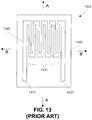
- FIG. 13 Illustrated in FIG. 13 is a conventional strain gauge, generally designated as 1300.
- the strain gauge 1300 comprises an input 1310 and an output 1320 connected by a plurality of windings 1330.
- the input 1310, output 1320, and plurality of windings 1330 are formed from a thin-film conductor 1340, such as a metal foil.
- the input 1310, output 1320, and plurality of windings 1330 are disposed on an insulative substrate 1350.
- the insulative substrate 1350 is adhered to a surface for which strain is desired to be measured. Strain is measured by sensing a resistance of the thin-film conductor 1340 as the strain gauge 1300 is deformed when under tension or compression. When stretched in a direction indicated by A or B in FIG. 13 , the resistance of the thin-film conductor 1340 increases. Thus, by measuring the increase in resistance, the tension of the surface to which the strain gauge 1300 is attached may be inferred. When compressed in a direction opposite to that indicated by A or B in FIG. 13 , the resistance of the thin-film conductor 1340 decreases. Thus, by measuring the decrease in resistance, the compression of the surface to which the strain gauge 1300 is attached may be inferred.
- S-shaped tension or compression sensors also known as load cells, typically incorporate one or more conventional strain gauges 1300 to sense tension or compression. Illustrated in FIG. 14 is a conventional S-shaped load cell, generally designated as 1400.
- the load cell 1400 comprises a first arm 1410, a second arm 1420, and a body 1430. Disposed on the body is a plurality of strain gauges 1440A through 1440D. Each strain gauge 1440 may be a strain gauge 1300.
- the load cell 1400 detects an amount of force applied in directions generally designed as C in FIG. 14 .
- the strain gauges 1440A and 1440D undergo compression, and the strain gauges 1440B and 1440D undergo tension. By measuring the tension and compression, the size of the force can be calculated.
- a tension sensor comprising a plate comprising a magnetoelastic region.
- the tension sensor further comprises at least one pair of sensors disposed above the magnetoelastic region.
- the at least one pair of sensors are configured to sense a change in a magnetic field produced by the magnetoelastic region in response to a strain in the plate imposed by a tension on the plate.
- a compression sensor comprising a plate comprising a magnetoelastic region.
- the compression sensor further comprises at least one pair of sensors disposed above the magnetoelastic region.
- the at least one pair of sensors are configured to sense a change in a magnetic field produced by the magnetoelastic region in response to a strain in the plate imposed by a compression on the plate.
- a magnetoelastic sensor comprises steps of forming a plate from an austenetic non-magnetic stainless steel alloy, cold-working an area of the plate to convert the austenetic non-magnetic stainless steel alloy in the area of the plate to martensite, rotating the plate, bringing a magnet near a surface of the plate and near the area of the plate converted to martensite to magnetize the area, and mounting at least one pair of magnetic field sensor assemblies above the surface of the plate near the magnetized area.
- FIG. 1 Illustrated in FIG. 1 is a top view of an exemplary embodiment of a magnetoelastic sensor, generally designated as 100, in accordance with an exemplary embodiment of the present invention.
- FIG. 2A illustrates a right-side view along a cross-section of the magnetoelastic sensor 100 at a section line 180
- FIG. 2B illustrates a left-side view along a cross-section of the magnetoelastic sensor 100 taken at a section line 170.
- the magnetoelastic sensor 100 comprises a plate 110, a first distribution bar 120 connected to the plate 110 at a first end 111 of the plate 110, and a second distribution bar 130 connected to the plate 110 at a second end 112 of the plate 110.
- a magnetic band 140 Disposed in the plate 110 is a magnetic band 140.
- the magnetic band 140 is an annulus.
- different shapes of the magnetic band 140 are contemplated.
- the magnetic band 140 may be diamond shaped.
- the plate 110 may have various dimensions, may not be perfectly planar on either surface, and may not have a perfectly uniform thickness across its entire length.
- Each of the sensor assemblies 150A, 150B, 150C, and 150D comprises, respectively, a sensor platform 152A, 152B, 152C, and 152D on which a respective sensor 154A, 154B, 154C, and 154D is disposed.
- the sensors 154A and 154C are disposed along the section line 170 (also referred to herein as "centerline 170").
- the sensors 154B and 154D are disposed along the section line 180 (also referred to herein as "centerline 180").
- the centerline 170 longitudinally bisects the sensor assemblies 150A and 150C and their respective sensors 154A and 154C.
- the center line 170 longitudinally bisects the sensor assemblies 150B and 150D and their respective sensors 154B and 154D.
- the sensors 154A, 154B, 154C, and 154D are disposed symmetrically about a center point 165 of the plate 110, which center point 165 is also the center point of the magnetic band 140.
- the sensors 154A, 154B, 154C, and 154D are disposed over the magnetic band 140 such that a centerline 145 of the magnetic band 140 laterally bisects the sensors 154A, 154B, 154C, and 154D.
- the sensor assemblies 150A, 150B, 150C, and 150D are disposed on the magnetic band 140 each at a respective angle, - ⁇ , ⁇ , - ⁇ , and ⁇ , relative to a longitudinal axis 160 of the plate 110.
- the angles, ⁇ and - ⁇ , are chosen so that the centerlines 170 and 180 are neither parallel to the longitudinal axis 160 nor perpendicular thereto.
- angles, ⁇ and - ⁇ are chosen so that the centerlines 170 and 180 intersect the magnetized band 140 perpendicularly to a tangent of the centerline 145 of the magnetic band 140, and where the magnetic field produced by the magnetic band 140 at the points of intersection is neither parallel nor perpendicular to the centerline 160 of the plate 110.
- the magnitude of angle, ⁇ , - ⁇ is chosen to be greater than or equal to 30° and less than or equal to 60°.
- the magnitude of angle, ⁇ , - ⁇ is chosen to be greater than or equal to 40° and less than or equal to 50°.
- the magnitude of angle, ⁇ , - ⁇ is 45°.
- the magnetic field sensors 154A, 154B, 154C, and 154D each produce an output signal that changes when a magnetic field produced by the magnetized band 140 in a direction parallel to the centerlines 170 and 180 changes.
- the magnetic field sensors 154A and 154C have high sensitivity to magnetic fields parallel to the centerline 170, and the magnetic field sensors 154B and 154D have high sensitivity to magnetic fields parallel to the centerline 180.
- the first and second distribution bars 120, 130 at the top 111 and the bottom 112 of the plate 110 are thicker than the plate 110.
- forces, F 1 and F 2 are applied to the distribution bars 120, 130, respectively, an even amount of strain or compression is produced in the plate 110, rather than a large amount of strain or compression along the center line 160 of the plate 110 and less elsewhere.
- the first and second distribution bars 120, 130 are formed integrally with the plate 110 and are areas of the plate that are thicker than the portion of the plate 110 in which the magnetized band 140 is disposed.
- forces, F 1 and F 2 are applied to the distribution bars 120, 130, respectively, an even amount of strain or compression is produced in the plate 110, rather than a large amount of strain along the center line 160 of the plate 110 and less elsewhere.
- the magnetic band 140 is formed within the plate 110.
- the magnetic band 140 may be formed from a magnetized band that is molded within a nonmagnetized or nonmagnetizable, e.g., non-ferromagnetic, plate 110.
- the magnetic band 140 may be a magnetized region of the plate 110, in which case the plate 110 is formed entirely from a ferromagnetic material. It is to be understood that other exemplary embodiments of the magnetoelastic sensor 100 in which the magnetic band 140 is disposed above or on a top surface 113 of the plate 110 are contemplated. In such other embodiments, the plate 110 is not magnetized and may be formed from a material that is not capable of being magnetized.
- the plate 110 is made from a non-magnetic material where the region 140 can be subjected to a process to change its metallurgical phase.
- a type of austenetic non-magnetic stainless steel alloy is selected to form the plate 110.
- the area corresponding to the region 140 is cold-worked to convert it to martensite, which is ferromagnetic.
- the plate 110 is rotated around an axis perpendicular to the center point 165 of the plate 110, and then while it is rotating, a permanent magnet is brought close to the surface 113 of the plate 110 near the area of the plate 110 corresponding to the region 140 for a large number of revolutions.
- the permanent magnet is removed after a magnetization direction has been imparted in the region 140.
- This approach is beneficial because forming the plate 110 from a homogeneously ferromagnetic material could lead to problems, and molding or attaching the region 140 could be problematic because of the extremely high interface shear stresses in the plate 110 in certain applications.
- Sensor assemblies in accordance with the exemplary embodiments described herein are then mounted above the surface 113 of the plate 110.
- the magnetized band 140 having a circumferential magnetization direction indicated by the arrowed centerline 145 in FIG. 1 is produced by rotating the plate 110 around an axis perpendicular to the center point 165 of the plate 110, and then while it is rotating, bringing a permanent magnet close to the surface 113 of the plate 110 for a large number of revolutions.
- the permanent magnet is removed after a magnetization direction has been imparted in the magnetic band 140, which is a magnetized region of the plate 110.
- the plate 110 is formed from a ferromagnetic material. It is to be understood that reference number 145 also refers to the magnetic field produced by the magnetic band 140. Sensor assemblies in accordance with the exemplary embodiments described herein are then mounted above the surface 113 of the plate 110.
- FIG. 1 illustrates a single magnetic band 140
- a plurality of permanent magnets placed at various azimuthal locations in the plate 110 can also be used.
- more than one magnetic band may be formed in or on the plate 110, in which case the magnetoelastic sensor comprises four sensor assemblies for each ring.
- an electromagnet is used to produce the magnetized band 140.
- FIG. 2A illustrates the relative positions of the sensor assemblies 150B and 150D and the plate 110.
- FIG. 2B illustrates the relative positions of the sensor assemblies 150A and 150C and the plate 110.
- the sensor platforms 152A, 152B, 152C, and 152D comprise, respectively, inside surfaces 151A, 151B, 151C, and 151D on which the sensors 154A, 154B, 154C, and 154D are respectively disposed.
- the sensor platforms 152A, 152B, 152C, and 152D further comprise, respectively, outside surfaces 153A, 153B, 153C, and 153D.
- the inside surfaces 151A, 151B, 151C, and 151D face the magnetic band 140 such that the sensors 154A, 154B, 154C, and 154D, as disposed on the respective inside surfaces 151A, 151B, 151C, and 151D, are between the magnetic band 140 and the respective sensor platforms 152A, 152B, 152C, and 152D.
- FIG. 3 illustrates a detailed view of a region 300 of the plate 110 under the sensor assembly 150C and specifically a region 300 of the magnetic band 140 under the sensor assembly 150C, in accordance with an exemplary embodiment of the present invention.
- a tension axis also referred to as a "magnetoelastic anisotropy axis" 310, a first effective anisotropy axis 320, and a second effective anisotropy axis 330.
- the first effective anisotropy axis 320 is the direction of the magnetic field 145 produced by the magnetic band 140 when the forces, F 1 and F 2 , are not present.
- the second effective anisotropy axis 330 is the direction of the magnetic field 145 produced by the magnetic band 140 when the forces, F 1 and F 2 , are present.
- the second effective anisotropy axis 330 is a result of the combination of the tension axis 310 and the first effective anisotropy axis 320 and is proportional to the strength of the forces, F 1 and F 2 .
- the first effective anisotropy axis 320 is offset from the second effective anisotropy axis 330 by an angle ⁇ , which changes as the magnitude of the forces, F 1 and F 2 , change.
- the angle, ⁇ increases as the magnitude of the forces, F 1 and F 2 , increase and decreases at the magnitude of the forces, F 1 and F 2 , decrease.
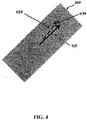
- FIG. 4 illustrates another detailed view of the region 300 of the plate 110, in accordance with an exemplary embodiment of the present invention.
- the view of the region 300 in FIG. 4 illustrates an effect of the tension caused by the forces, F 1 and F 2 .
- the magnetic field 145 in the magnetic band 140 is represented in FIG. 4 by a vector 410.
- the magnetic field 410 inside the magnetic band 145 changes direction to a direction represented by a vector 420.
- the change in magnetic field is represented by a vector 430, which is perpendicular to the vector 410, the sum of the vectors 410 and 430 being the vector 420.
- the change of the magnetic field i.e., the magnetic field component 430
- the sensor 154C is positioned to detect the change in the magnetic field 430 outside the plate 140.
- the sensor 154C is positioned to be especially sensitive to magnetic fields in an outwardly radial direction, i.e., in a direction parallel to the centerline 170.
- the sensor 154C is positioned to sense the component of the magnetic field outside the plate 140 caused by the magnetic field component 430.
- the sensor 154C is configured to output a signal indicative of the magnetic field 430 when the tension caused by the forces, F 1 and F 2 , is present.
- the sensors 154A, 154B, and 154D are positioned similarly to the sensor 154C.
- the sensor 154A is positioned to be especially sensitive to magnetic fields in an outwardly radial direction, i.e., in a direction parallel to the centerline 170.
- the sensors 154B and 154D are positioned to be especially sensitive to magnetic fields in a direction parallel to the centerline 180.
- the sensors 154A, 154B, and 154D are positioned to sense a component of the magnetic field outside the plate 140 caused by a change of the magnetic field outside of the plate 110 because of tension in the plate 110.
- FIGS. 3 and 4 are described with reference to a tension in the plate 110, it is to be understood that such description is applicable to an instance in which the forces, F 1 and F 2 , cause compression in the plate 110. Under compression, however, the changes in the anisotropy axis and the magnetic fields are opposite to the changes described with reference to FIGS. 3 and 4 when tension is present.
- FIG. 5 there is illustrated the magnetoelasic tension sensor 100 of FIG. 1 annotated to show strain axes 510 and 520, in accordance with an exemplary embodiment of the present invention.
- the strain axis 510 passes through a center point of the sensor 154C and the center point of the sensor 154B.
- the strain axis 520 passes through a center point of the sensor 154D, and the center point of the sensor 154A.
- the sensor assembly 150A is positioned to sense a portion 145A of the magnetic field 145; sensor assembly 150B is positioned to sense a portion 145B of the magnetic field 145; sensor assembly 150C is positioned to sense a portion 145C of the magnetic field 145; and sensor assembly 150D is positioned to sense a portion 145D of the magnetic field 145.
- the sensors 154A through 154D produce respective signals indicative of the magnetic fields that they sense.
- Each sensor signal produced by the sensors 154A through 154D comprises a first component resulting from the tension or compression in the plate 110 caused by the forces, F 1 and F 2 , and a second component resulting from environmental magnetic field(s).
- the first components of the sensor signals provided by the magnetic field sensors 154A, 154B, 154C, and 154D in response to the tension or compression created by the forces, F 1 and F 2 add constructively.
- the second component of the sensor signals provided by the magnetic field sensors 154A, 154B, 154C, and 154D in response to environmental magnetic fields largely add destructively.
- the final sensor output (described below with reference to FIG. 11 ) is mostly insensitive to environmental magnetic fields.
- FIG. 6 there are illustrated various directions of the changes in the magnetic fields produced at the locations of the sensor assemblies 150A, 150B, 150C, and 150D as a result of tension in the plate 110, in accordance with an exemplary embodiment of the present invention.
- the magnetic field 145A under the sensor assembly 150A changes, as represented by a vector 650A
- the magnetic field 145B under the sensor assembly 150B changes, as represented by a vector 650B
- the magnetic field 145C under the sensor assembly 150C changes, as represented by a vector 650C
- the magnetic field 145D under the sensor assembly 150D changes, as represented by a vector 650D.
- the angles of the vectors 650A, 650B, 650C, and 650D are - ⁇ , ⁇ , ⁇ , and - ⁇ relative to the centerline 160 of the plate 110 (illustrated in FIG. 1 ).
- Providing for the magnetic field sensors 154A, 154B, 154C, and 154D to have identical polarity of sensitivity to the changes 650A, 650B, 650C, and 650D in the magnetic field 145 produced by the magnetized band 140 causes the sensitivity of the final sensor output to the tension to be high.
- the direction of the vector 650C is the same as the vector 430.
- the magnetic field sensors 154A, 154B, 154C are fluxgate magnetometers. In another exemplary embodiment, the magnetic field sensors 154A, 154B, 154C are Hall sensors.
- the various embodiments of the magnetoelastic sensor 100 described herein are advantageous in that the magnetic field sensors 154A, 154B, 154C, and 154D sense very little magnetic field when the tension or compression is not present. This is the result of the magnetic band 140 being ring shaped or generally symmetrical about the center point 165.
- the magnetoelastic sensor 100 ideally has no unpaired magnetic poles where the sensor assemblies 150A, 150B, 150C, and 150D are disposed.
- FIG. 7 Illustrated in FIG. 7 is an exemplary alternative embodiment of the magnetoelastic sensor 100, generally designated in FIG. 7 as 700, in accordance with an exemplary embodiment of the present invention.
- the sensor assemblies 150A through 150D are replaced with sensor assemblies 750A through 750D.
- the magnetoelastic sensor 700 is otherwise similar to the magnetoelastic sensor 100.
- FIGS. 8A and 8B Illustrated in FIGS. 8A and 8B are cross-sectional views of the magnetoelastic sensor 700, in accordance with an exemplary embodiment of the present invention.
- FIG. 8A illustrates a right-side view along a cross-section of the magnetoelastic sensor 700 at the centerline 180
- FIG. 8B illustrates a left-side view along a cross-section of the magnetoelastic sensor 700 taken at the centerline 170.
- the sensor assemblies 750A through 750D comprise respective sensor platforms 752A, 752B, 752C, and 752D, respectively, having inside surfaces 751A, 751B, 751C, and 751D and outside surfaces 753A, 753B, 753C, and 753D.
- the sensor assemblies 750A through 750D further comprise, respectively, first sensors 754A, 754B, 754C, and 754D disposed, respectively, on the inside surfaces 751A, 751B, 751C, and 751D and second sensors 755A, 755B, 755C, and 755D disposed, respectively, on the outside surfaces 753A, 753B, 753C, and 753D.
- the first sensors 754A, 754B, 754C, and 754D and the second sensors 756A, 756B, 756C, and 756D are symmetrically disposed about the center point 165 of the plate 110.
- the second sensors 756A, 756B, 756C, and 756D are disposed near the first sensors 754A, 754B, 754C, and 754D but at a distance greater from the magnetic band 140 than the first sensors 754A, 754B, 754C, and 754D.
- the first sensors 754A, 754B, 754C, and 754D are chosen to have a direction of sensitivity opposite (180°) from their respective paired second sensors 756A, 756B, 756C, and 756D.
- the pairing reduces the sensitivity of the magnetoelastic sensor 700 to ambient magnetic fields compared to the magnetoelastic sensor 100.
- the first sensors 754A and 754C are disposed above the magnetic band 140 along the centerline 170, and the first sensors 754B and 754D are disposed above the magnetic band 140 along the centerline 180.
- the centerline 170 longitudinally bisects the first sensors 754A and 754C, and the centerline 180 longitudinally bisects the first sensors 754B and 754D.
- the sensors 754A, 754B, 754C, and 754D are disposed over the magnetic band 140 such that a centerline 145 of the magnetic band 140 laterally bisects the sensors 754A, 754B, 754C, and 754D.
- the second sensors 756A and 755C are respectively disposed above the first sensors 754A and 754C along the centerline 170, and the second sensors 756B and 756D are respectively disposed above the first sensors 754B and 754D along the centerline 180.
- the centerline 170 longitudinally bisects the second sensors 756A and 756C, and the centerline 180 longitudinally bisects the second sensors 756B and 756D.
- the sensors 755A, 755B, 755C, and 755D are disposed over the magnetic band 140 such that a centerline 145 of the magnetic band 140 laterally bisects the sensors 755A, 755B, 755C, and 755D.
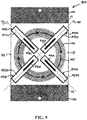
- FIGS. 9 , 10A , and 10B illustrate an exemplary alternative embodiment of the magnetoelastic sensor 700, generally designated in FIGS. 9 , 10A , and 10B as 900, in accordance with an exemplary embodiment of the present invention.
- FIGS. 10A and 10B illustrate cross-sections of the magnetoelastic sensor 900 taken along the centerlines 180 and 170, respectively.
- the magnetoelastic sensor 900 comprises the elements of the magnetoelastic sensor 700.
- the sensor assemblies 750A through 750D are replaced with sensor assemblies 950A through 950D.
- the sensor assemblies 950A through 950D comprise respective sensor platforms 952A, 952B, 952C, and 952D respectively having inside surfaces 951A, 951B, 951C, and 951D and outside surfaces 953A, 953B, 953C, and 953D.
- the sensor assemblies 950A through 950D further comprise, respectively, first sensors 954A, 954B, 954C, and 954D disposed, respectively, on the inside surfaces 951A, 951B, 951C, and 951D and second sensors 956A, 956B, 956C, and 956D disposed, respectively, on the outside surfaces 953A, 953B, 953C, and 953D.
- the sensor assemblies 950A through 950D are similar to the sensor assemblies 750A through 750D, but they differ in that the second sensors 956A, 956B, 956C, and 956D are inset radially relative to the center point 165 of the magnetic band 140 compared to the second sensors 755A, 755B, 755C, and 755D. This inset is best seen in FIG. 9 .
- the magnetoelastic sensor 700 includes no such inset.
- the sensor assembly 1100 comprises a magnetoelastic sensor 100, 700, or 900 connected to circuitry 1110 via a communications link 1115.
- the magnetoelastic sensor 100, 700, or 900 outputs the signals from its sensor assemblies via the communications link 1115 to the circuitry 1110.
- the circuitry 1110 combines the signals provided by the sensor assemblies and outputs the combined signal via an output 1120.
- the output 1120 indicates the amount of tension or compression sensed by the magnetoelastic sensor 100, 700, or 900.
- FIG. 12 there is illustrated a graph of data from a test of an exemplary implementation of the magnetoelastic sensor 100. Weights were hung from the exemplary implementation of the magnetoelastic sensor 100, and the output voltage was recorded. The slope in the graph shows a sensitivity of 0.56 mV/pound.
Abstract
Description
- This application claims the benefit of
U.S. Provisional Application No. 61/921,757 U.S. Provisional Application No. 61/925,509 - The present invention relates to a magnetoeleastic sensor and, more specifically, to a magnetoelastic sensor for sensing tension or compression.
- Conventional tension and compression sensors use strain gauges to produce electrical signals which indicate the tension or compression present. Illustrated in
FIG. 13 is a conventional strain gauge, generally designated as 1300. Thestrain gauge 1300 comprises aninput 1310 and anoutput 1320 connected by a plurality ofwindings 1330. Theinput 1310,output 1320, and plurality ofwindings 1330 are formed from a thin-film conductor 1340, such as a metal foil. Theinput 1310,output 1320, and plurality ofwindings 1330 are disposed on aninsulative substrate 1350. - The
insulative substrate 1350 is adhered to a surface for which strain is desired to be measured. Strain is measured by sensing a resistance of the thin-film conductor 1340 as thestrain gauge 1300 is deformed when under tension or compression. When stretched in a direction indicated by A or B inFIG. 13 , the resistance of the thin-film conductor 1340 increases. Thus, by measuring the increase in resistance, the tension of the surface to which thestrain gauge 1300 is attached may be inferred. When compressed in a direction opposite to that indicated by A or B inFIG. 13 , the resistance of the thin-film conductor 1340 decreases. Thus, by measuring the decrease in resistance, the compression of the surface to which thestrain gauge 1300 is attached may be inferred. - S-shaped tension or compression sensors, also known as load cells, typically incorporate one or more
conventional strain gauges 1300 to sense tension or compression. Illustrated inFIG. 14 is a conventional S-shaped load cell, generally designated as 1400. Theload cell 1400 comprises afirst arm 1410, asecond arm 1420, and a body 1430. Disposed on the body is a plurality ofstrain gauges 1440A through 1440D. Each strain gauge 1440 may be astrain gauge 1300. - The
load cell 1400 detects an amount of force applied in directions generally designed as C inFIG. 14 . When the force is applied in the directions C, thestrain gauges strain gauges - Conventional tension sensors using magnetoelastic effects are described in
U.S. Patent Nos. 5,195,377 to Garshelis , andU.S. Patent No. 6,220,105 to Cripe . A conventional Villari effect tension sensor is described inU.S. Patent No. 5,905,210 to O'Boyle et al. - In accordance with an aspect of the present invention, there is provided a tension sensor comprising a plate comprising a magnetoelastic region. The tension sensor further comprises at least one pair of sensors disposed above the magnetoelastic region. The at least one pair of sensors are configured to sense a change in a magnetic field produced by the magnetoelastic region in response to a strain in the plate imposed by a tension on the plate.
- In accordance with another aspect of the present invention, there is provided a compression sensor comprising a plate comprising a magnetoelastic region. The compression sensor further comprises at least one pair of sensors disposed above the magnetoelastic region. The at least one pair of sensors are configured to sense a change in a magnetic field produced by the magnetoelastic region in response to a strain in the plate imposed by a compression on the plate.
- In accordance with yet another aspect of the present invention, there is provided method of manufacturing a magnetoelastic sensor. The method comprises steps of forming a plate from an austenetic non-magnetic stainless steel alloy, cold-working an area of the plate to convert the austenetic non-magnetic stainless steel alloy in the area of the plate to martensite, rotating the plate, bringing a magnet near a surface of the plate and near the area of the plate converted to martensite to magnetize the area, and mounting at least one pair of magnetic field sensor assemblies above the surface of the plate near the magnetized area.
- For the purpose of illustration, there are shown in the drawings certain embodiments of the present invention. In the drawings, like numerals indicate like elements throughout. It should be understood that the invention is not limited to the precise arrangements, dimensions, and instruments shown. In the drawings:
-
FIG. 1 is top view of a magnetoelastic tension sensor comprising a plate and a plurality of sensor assemblies, in accordance with an exemplary embodiment of the present invention; -
FIG. 2A is a first cross-sectional view of the magnetoelastic tension sensor ofFIG. 1 , in accordance with an exemplary embodiment of the present invention; -
FIG. 2B is a second cross-sectional view of the magnetoelastic tension sensor ofFIG. 1 , in accordance with an exemplary embodiment of the present invention; -
FIG. 3 illustrates a detailed view of a region of the plate of the magnetoelastic tension sensor ofFIG. 1 , in accordance with an exemplary embodiment of the present invention; -
FIG. 4 illustrates another detailed view of a region of the plate of the magnetoelastic tension sensor ofFIG. 1 , in accordance with an exemplary embodiment of the present invention; -
FIG. 5 illustrates another view of the magnetoelasic tension sensor ofFIG. 1 , in accordance with an exemplary embodiment of the present invention; -
FIG. 6 illustrates various directions of changes in magnetic fields produced at the sensor assemblies of the magnetoelasic tension sensor ofFIG. 1 , in accordance with an exemplary embodiment of the present invention; -
FIG. 7 illustrates an exemplary alternative embodiment of the magnetoelastic tension sensor ofFIG. 1 , in accordance with an exemplary embodiment of the present invention; -
FIG. 8A illustrates a first cross-sectional view the magnetoelastic tension sensor ofFIG. 7 , in accordance with an exemplary embodiment of the present invention; -
FIG. 8B illustrates a second cross-sectional view the magnetoelastic tension sensor ofFIG. 7 , in accordance with an exemplary embodiment of the present invention; -
FIG. 8 illustrate an exemplary alternative embodiment of the magnetoelastic tension sensor ofFIG. 1 , in accordance with an exemplary embodiment of the present invention; -
FIG. 9 illustrates an exemplary alternative embodiment of the magnetoelastic tension sensor ofFIG. 7 , in accordance with an exemplary embodiment of the present invention; -
FIG. 10A is a first cross-sectional view of the magnetoelastic tension sensor ofFIG. 9 , in accordance with an exemplary embodiment of the present invention; -
FIG. 10B is a second cross-sectional view of the magnetoelastic tension sensor ofFIG. 9 , in accordance with an exemplary embodiment of the present invention; -
FIG. 11 illustrates a sensor assembly comprising the magnetoelastic tension sensor ofFIGS. 1 ,7 , or9 , in accordance with an exemplary embodiment of the present invention; -
FIG. 12 illustrates a graph of data from a test of an exemplary implementation of the magnetoelastic tension sensor ofFIG. 1 , in accordance with an exemplary embodiment of the present invention; -
FIG. 13 illustrates a conventional strain gauge; and -
FIG. 14 illustrates a conventional load cell. - Reference to the drawings illustrating various views of exemplary embodiments of the present invention is now made. In the drawings and the description of the drawings herein, certain terminology is used for convenience only and is not to be taken as limiting the embodiments of the present invention. Furthermore, in the drawings and the description below, like numerals indicate like elements throughout.
- Illustrated in
FIG. 1 is a top view of an exemplary embodiment of a magnetoelastic sensor, generally designated as 100, in accordance with an exemplary embodiment of the present invention.FIG. 2A illustrates a right-side view along a cross-section of themagnetoelastic sensor 100 at a section line 180, andFIG. 2B illustrates a left-side view along a cross-section of themagnetoelastic sensor 100 taken at asection line 170. - Referring to
FIGS. 1 ,2A , and2B , themagnetoelastic sensor 100 comprises aplate 110, afirst distribution bar 120 connected to theplate 110 at a first end 111 of theplate 110, and asecond distribution bar 130 connected to theplate 110 at asecond end 112 of theplate 110. Disposed in theplate 110 is amagnetic band 140. In the exemplary embodiment of themagnetic band 140 illustrated inFIG. 1 , themagnetic band 140 is an annulus. In other exemplary embodiments of themagnetic band 140, different shapes of themagnetic band 140 are contemplated. For example, themagnetic band 140 may be diamond shaped. It is to be understood that theplate 110 may have various dimensions, may not be perfectly planar on either surface, and may not have a perfectly uniform thickness across its entire length. - Disposed above the
magnetic band 140 are a plurality ofsensor assemblies sensor assemblies sensor platform centerline 170"). The sensors 154B and 154D are disposed along the section line 180 (also referred to herein as "centerline 180"). Thecenterline 170 longitudinally bisects thesensor assemblies 150A and 150C and their respective sensors 154A and 154C. Thecenter line 170 longitudinally bisects thesensor assemblies plate 110, which center point 165 is also the center point of themagnetic band 140. The sensors 154A, 154B, 154C, and 154D are disposed over themagnetic band 140 such that acenterline 145 of themagnetic band 140 laterally bisects the sensors 154A, 154B, 154C, and 154D. - The
sensor assemblies magnetic band 140 each at a respective angle, -α, α, -α, and α, relative to alongitudinal axis 160 of theplate 110. The angles, α and -α, are chosen so that thecenterlines 170 and 180 are neither parallel to thelongitudinal axis 160 nor perpendicular thereto. - In an exemplary embodiment, the angles, α and -α, are chosen so that the
centerlines 170 and 180 intersect themagnetized band 140 perpendicularly to a tangent of thecenterline 145 of themagnetic band 140, and where the magnetic field produced by themagnetic band 140 at the points of intersection is neither parallel nor perpendicular to thecenterline 160 of theplate 110. - In another exemplary embodiment, the magnitude of angle, α, -α, is chosen to be greater than or equal to 30° and less than or equal to 60°.
- In yet another exemplary embodiment, the magnitude of angle, α, -α, is chosen to be greater than or equal to 40° and less than or equal to 50°.
- In still another exemplary embodiment, the magnitude of angle, α, -α, is 45°.
- The magnetic field sensors 154A, 154B, 154C, and 154D each produce an output signal that changes when a magnetic field produced by the
magnetized band 140 in a direction parallel to thecenterlines 170 and 180 changes. The magnetic field sensors 154A and 154C have high sensitivity to magnetic fields parallel to thecenterline 170, and the magnetic field sensors 154B and 154D have high sensitivity to magnetic fields parallel to the centerline 180. - The first and second distribution bars 120, 130 at the top 111 and the
bottom 112 of theplate 110 are thicker than theplate 110. Thus, as forces, F1 and F2, are applied to the distribution bars 120, 130, respectively, an even amount of strain or compression is produced in theplate 110, rather than a large amount of strain or compression along thecenter line 160 of theplate 110 and less elsewhere. - In an alternative exemplary embodiment of the
magnetoelastic sensor 100, the first and second distribution bars 120, 130 are formed integrally with theplate 110 and are areas of the plate that are thicker than the portion of theplate 110 in which themagnetized band 140 is disposed. In such embodiment, as forces, F1 and F2, are applied to the distribution bars 120, 130, respectively, an even amount of strain or compression is produced in theplate 110, rather than a large amount of strain along thecenter line 160 of theplate 110 and less elsewhere. - In the exemplary embodiment of the
magnetoelastic sensor 100 described above, themagnetic band 140 is formed within theplate 110. In such embodiment, themagnetic band 140 may be formed from a magnetized band that is molded within a nonmagnetized or nonmagnetizable, e.g., non-ferromagnetic,plate 110. - In another exemplary embodiment of the
magnetoelastic sensor 100, themagnetic band 140 may be a magnetized region of theplate 110, in which case theplate 110 is formed entirely from a ferromagnetic material. It is to be understood that other exemplary embodiments of themagnetoelastic sensor 100 in which themagnetic band 140 is disposed above or on atop surface 113 of theplate 110 are contemplated. In such other embodiments, theplate 110 is not magnetized and may be formed from a material that is not capable of being magnetized. - In yet another exemplary embodiment of the
magnetoelastic sensor 100, theplate 110 is made from a non-magnetic material where theregion 140 can be subjected to a process to change its metallurgical phase. A type of austenetic non-magnetic stainless steel alloy is selected to form theplate 110. The area corresponding to theregion 140 is cold-worked to convert it to martensite, which is ferromagnetic. Theplate 110 is rotated around an axis perpendicular to the center point 165 of theplate 110, and then while it is rotating, a permanent magnet is brought close to thesurface 113 of theplate 110 near the area of theplate 110 corresponding to theregion 140 for a large number of revolutions. The permanent magnet is removed after a magnetization direction has been imparted in theregion 140. This approach is beneficial because forming theplate 110 from a homogeneously ferromagnetic material could lead to problems, and molding or attaching theregion 140 could be problematic because of the extremely high interface shear stresses in theplate 110 in certain applications. Sensor assemblies in accordance with the exemplary embodiments described herein are then mounted above thesurface 113 of theplate 110. - In an exemplary embodiment in which the
plate 110 is formed from a ferromagnetic material, themagnetized band 140 having a circumferential magnetization direction indicated by thearrowed centerline 145 inFIG. 1 is produced by rotating theplate 110 around an axis perpendicular to the center point 165 of theplate 110, and then while it is rotating, bringing a permanent magnet close to thesurface 113 of theplate 110 for a large number of revolutions. The permanent magnet is removed after a magnetization direction has been imparted in themagnetic band 140, which is a magnetized region of theplate 110. In this exemplary embodiment, theplate 110 is formed from a ferromagnetic material. It is to be understood thatreference number 145 also refers to the magnetic field produced by themagnetic band 140. Sensor assemblies in accordance with the exemplary embodiments described herein are then mounted above thesurface 113 of theplate 110. - Although
FIG. 1 illustrates a singlemagnetic band 140, it is to be understood that other exemplary embodiments in which a plurality of permanent magnets placed at various azimuthal locations in theplate 110 can also be used. In other exemplary embodiments, more than one magnetic band may be formed in or on theplate 110, in which case the magnetoelastic sensor comprises four sensor assemblies for each ring. In still other exemplary embodiments, instead of a permanent magnet forming themagnetic band 140, an electromagnet is used to produce themagnetized band 140. -
FIG. 2A illustrates the relative positions of thesensor assemblies plate 110.FIG. 2B illustrates the relative positions of thesensor assemblies 150A and 150C and theplate 110. - As illustrated in
FIGS. 2A and2B , thesensor platforms sensor platforms magnetic band 140 such that the sensors 154A, 154B, 154C, and 154D, as disposed on the respectiveinside surfaces 151A, 151B, 151C, and 151D, are between themagnetic band 140 and therespective sensor platforms -
FIG. 3 illustrates a detailed view of aregion 300 of theplate 110 under the sensor assembly 150C and specifically aregion 300 of themagnetic band 140 under the sensor assembly 150C, in accordance with an exemplary embodiment of the present invention. Inside thisregion 300, there are illustrated a tension axis (also referred to as a "magnetoelastic anisotropy axis") 310, a firsteffective anisotropy axis 320, and a second effective anisotropy axis 330. - The first
effective anisotropy axis 320 is the direction of themagnetic field 145 produced by themagnetic band 140 when the forces, F1 and F2, are not present. The second effective anisotropy axis 330 is the direction of themagnetic field 145 produced by themagnetic band 140 when the forces, F1 and F2, are present. The second effective anisotropy axis 330 is a result of the combination of thetension axis 310 and the firsteffective anisotropy axis 320 and is proportional to the strength of the forces, F1 and F2. The firsteffective anisotropy axis 320 is offset from the second effective anisotropy axis 330 by an angle β, which changes as the magnitude of the forces, F1 and F2, change. The angle, β, increases as the magnitude of the forces, F1 and F2, increase and decreases at the magnitude of the forces, F1 and F2, decrease. -
FIG. 4 illustrates another detailed view of theregion 300 of theplate 110, in accordance with an exemplary embodiment of the present invention. The view of theregion 300 inFIG. 4 illustrates an effect of the tension caused by the forces, F1 and F2. Themagnetic field 145 in themagnetic band 140 is represented inFIG. 4 by avector 410. As the direction of the effectivefirst anisotropy axis 320 changes to the direction of the second anisotropy axis 330, themagnetic field 410 inside themagnetic band 145 changes direction to a direction represented by avector 420. The change in magnetic field is represented by avector 430, which is perpendicular to thevector 410, the sum of thevectors vector 420. - The change of the magnetic field, i.e., the
magnetic field component 430, produces a change in the magnetic field outside theplate 110 in theregion 300. The sensor 154C is positioned to detect the change in themagnetic field 430 outside theplate 140. The sensor 154C is positioned to be especially sensitive to magnetic fields in an outwardly radial direction, i.e., in a direction parallel to thecenterline 170. Thus, the sensor 154C is positioned to sense the component of the magnetic field outside theplate 140 caused by themagnetic field component 430. The sensor 154C is configured to output a signal indicative of themagnetic field 430 when the tension caused by the forces, F1 and F2, is present. - The sensors 154A, 154B, and 154D are positioned similarly to the sensor 154C. Thus, the sensor 154A is positioned to be especially sensitive to magnetic fields in an outwardly radial direction, i.e., in a direction parallel to the
centerline 170. The sensors 154B and 154D are positioned to be especially sensitive to magnetic fields in a direction parallel to the centerline 180. The sensors 154A, 154B, and 154D are positioned to sense a component of the magnetic field outside theplate 140 caused by a change of the magnetic field outside of theplate 110 because of tension in theplate 110. - Although
FIGS. 3 and4 are described with reference to a tension in theplate 110, it is to be understood that such description is applicable to an instance in which the forces, F1 and F2, cause compression in theplate 110. Under compression, however, the changes in the anisotropy axis and the magnetic fields are opposite to the changes described with reference toFIGS. 3 and4 when tension is present. - Referring now to
FIG. 5 , there is illustrated themagnetoelasic tension sensor 100 ofFIG. 1 annotated to show strain axes 510 and 520, in accordance with an exemplary embodiment of the present invention. The strain axis 510 passes through a center point of the sensor 154C and the center point of the sensor 154B. Thestrain axis 520 passes through a center point of the sensor 154D, and the center point of the sensor 154A. - The
sensor assembly 150A is positioned to sense aportion 145A of themagnetic field 145;sensor assembly 150B is positioned to sense aportion 145B of themagnetic field 145; sensor assembly 150C is positioned to sense a portion 145C of themagnetic field 145; andsensor assembly 150D is positioned to sense a portion 145D of themagnetic field 145. The sensors 154A through 154D produce respective signals indicative of the magnetic fields that they sense. - Each sensor signal produced by the sensors 154A through 154D comprises a first component resulting from the tension or compression in the
plate 110 caused by the forces, F1 and F2, and a second component resulting from environmental magnetic field(s). When connected correctly to electronic circuitry (described below with reference toFIG. 11 ), the first components of the sensor signals provided by the magnetic field sensors 154A, 154B, 154C, and 154D in response to the tension or compression created by the forces, F1 and F2, add constructively. The second component of the sensor signals provided by the magnetic field sensors 154A, 154B, 154C, and 154D in response to environmental magnetic fields largely add destructively. Thus, the final sensor output (described below with reference toFIG. 11 ) is mostly insensitive to environmental magnetic fields. - Referring now to
FIG. 6 , there are illustrated various directions of the changes in the magnetic fields produced at the locations of thesensor assemblies plate 110, in accordance with an exemplary embodiment of the present invention. When theplate 110 is placed under tension, themagnetic field 145A under thesensor assembly 150A changes, as represented by a vector 650A; themagnetic field 145B under thesensor assembly 150B changes, as represented by avector 650B; the magnetic field 145C under the sensor assembly 150C changes, as represented by a vector 650C; and the magnetic field 145D under thesensor assembly 150D changes, as represented by a vector 650D. - The angles of the
vectors 650A, 650B, 650C, and 650D are -α, α, α, and -α relative to thecenterline 160 of the plate 110 (illustrated inFIG. 1 ). Providing for the magnetic field sensors 154A, 154B, 154C, and 154D to have identical polarity of sensitivity to thechanges 650A, 650B, 650C, and 650D in themagnetic field 145 produced by themagnetized band 140 causes the sensitivity of the final sensor output to the tension to be high. Note that the direction of the vector 650C is the same as thevector 430. - In one exemplary embodiment, the magnetic field sensors 154A, 154B, 154C are fluxgate magnetometers. In another exemplary embodiment, the magnetic field sensors 154A, 154B, 154C are Hall sensors.
- The various embodiments of the
magnetoelastic sensor 100 described herein are advantageous in that the magnetic field sensors 154A, 154B, 154C, and 154D sense very little magnetic field when the tension or compression is not present. This is the result of themagnetic band 140 being ring shaped or generally symmetrical about the center point 165. Thus, themagnetoelastic sensor 100 ideally has no unpaired magnetic poles where thesensor assemblies - Illustrated in
FIG. 7 is an exemplary alternative embodiment of themagnetoelastic sensor 100, generally designated inFIG. 7 as 700, in accordance with an exemplary embodiment of the present invention. In themagnetoelastic sensor 700, thesensor assemblies 150A through 150D are replaced withsensor assemblies 750A through 750D. Themagnetoelastic sensor 700 is otherwise similar to themagnetoelastic sensor 100. - Illustrated in
FIGS. 8A and8B are cross-sectional views of themagnetoelastic sensor 700, in accordance with an exemplary embodiment of the present invention.FIG. 8A illustrates a right-side view along a cross-section of themagnetoelastic sensor 700 at the centerline 180, andFIG. 8B illustrates a left-side view along a cross-section of themagnetoelastic sensor 700 taken at thecenterline 170. - The
sensor assemblies 750A through 750D compriserespective sensor platforms outside surfaces sensor assemblies 750A through 750D further comprise, respectively,first sensors 754A, 754B, 754C, and 754D disposed, respectively, on theinside surfaces 751A, 751B, 751C, and 751D and second sensors 755A, 755B, 755C, and 755D disposed, respectively, on theoutside surfaces first sensors 754A, 754B, 754C, and 754D and thesecond sensors plate 110. - The
second sensors first sensors 754A, 754B, 754C, and 754D but at a distance greater from themagnetic band 140 than thefirst sensors 754A, 754B, 754C, and 754D. Thefirst sensors 754A, 754B, 754C, and 754D are chosen to have a direction of sensitivity opposite (180°) from their respective pairedsecond sensors magnetoelastic sensor 700 to ambient magnetic fields compared to themagnetoelastic sensor 100. - The
first sensors 754A and 754C are disposed above themagnetic band 140 along thecenterline 170, and the first sensors 754B and 754D are disposed above themagnetic band 140 along the centerline 180. Thecenterline 170 longitudinally bisects thefirst sensors 754A and 754C, and the centerline 180 longitudinally bisects the first sensors 754B and 754D. Thesensors 754A, 754B, 754C, and 754D are disposed over themagnetic band 140 such that acenterline 145 of themagnetic band 140 laterally bisects thesensors 754A, 754B, 754C, and 754D. - The
second sensors 756A and 755C are respectively disposed above thefirst sensors 754A and 754C along thecenterline 170, and thesecond sensors 756B and 756D are respectively disposed above the first sensors 754B and 754D along the centerline 180. Thecenterline 170 longitudinally bisects thesecond sensors 756A and 756C, and the centerline 180 longitudinally bisects thesecond sensors 756B and 756D. The sensors 755A, 755B, 755C, and 755D are disposed over themagnetic band 140 such that acenterline 145 of themagnetic band 140 laterally bisects the sensors 755A, 755B, 755C, and 755D. -
FIGS. 9 ,10A , and10B illustrate an exemplary alternative embodiment of themagnetoelastic sensor 700, generally designated inFIGS. 9 ,10A , and10B as 900, in accordance with an exemplary embodiment of the present invention.FIGS. 10A and10B illustrate cross-sections of themagnetoelastic sensor 900 taken along thecenterlines 180 and 170, respectively. Themagnetoelastic sensor 900 comprises the elements of themagnetoelastic sensor 700. In themagnetoelastic sensor 900, thesensor assemblies 750A through 750D are replaced withsensor assemblies 950A through 950D. - The
sensor assemblies 950A through 950D compriserespective sensor platforms 952A, 952B, 952C, and 952D respectively having inside surfaces 951A, 951B, 951C, and 951D andoutside surfaces 953A, 953B, 953C, and 953D. Thesensor assemblies 950A through 950D further comprise, respectively,first sensors 954A, 954B, 954C, and 954D disposed, respectively, on the inside surfaces 951A, 951B, 951C, and 951D andsecond sensors outside surfaces 953A, 953B, 953C, and 953D. - The
sensor assemblies 950A through 950D are similar to thesensor assemblies 750A through 750D, but they differ in that thesecond sensors magnetic band 140 compared to the second sensors 755A, 755B, 755C, and 755D. This inset is best seen inFIG. 9 . Themagnetoelastic sensor 700 includes no such inset. - Referring now to
FIG. 11 , there is illustrated a schematic drawing of an exemplary embodiment of a sensor assembly, generally designated as 1100, in accordance with an exemplary embodiment of the present invention. The sensor assembly 1100 comprises amagnetoelastic sensor magnetoelastic sensor magnetoelastic sensor - Referring now to
FIG. 12 , there is illustrated a graph of data from a test of an exemplary implementation of themagnetoelastic sensor 100. Weights were hung from the exemplary implementation of themagnetoelastic sensor 100, and the output voltage was recorded. The slope in the graph shows a sensitivity of 0.56 mV/pound. - These and other advantages of the present invention will be apparent to those skilled in the art from the foregoing specification. Accordingly, it is to be recognized by those skilled in the art that changes or modifications may be made to the above-described embodiments without departing from the broad inventive concepts of the invention. It is to be understood that this invention is not limited to the particular embodiments described herein, but is intended to include all changes and modifications that are within the scope and spirit of the invention.
-
- 1. A tension sensor comprising:
- a plate comprising a magnetoelastic region;
- at least one pair of sensors disposed above the magnetoelastic region, the at least one pair of sensors configured to sense a change in a magnetic field produced by the magnetoelastic region in response to a strain in the plate imposed by a tension on the plate.
- 2. The tension sensor of
item 1, wherein the magnetoelastic region is symmetrical about a centerpoint of the magnetoelastic region. - 3. The tension sensor of
item 1, where the at least one pair of sensors are symmetrically disposed above the magnetoelastic region about a centerpoint of the magnetoelastic region. - 4. The tension sensor of
item 1, further comprising at least one pair of sensor platforms on which the at least one pair of sensors are respectively disposed. - 5. The tension sensor of item 4, wherein the at least one pair of sensors are disposed between the respective at least one pair of sensors and the magnetoelastic region.
- 6. The tension sensor of
item 1, further comprising a second pair of sensors respectively disposed on the at least one pair of sensor platforms on a side of the respective at least one pair of sensor platforms opposite the respective at least one pair of sensors. - 7. The tension sensor of item 6, wherein the second pair of sensors are radially inset relative to the at least one pair of sensors.
- 8. The tension sensor of
item 1, wherein the magnetoelastic region is annular. - 9. The tension sensor of item 8, wherein each of the at least one pair of sensors is bisected laterally by the magnetoelastic region.
- 10. The tension sensor of item 9, wherein each of the at least one pair of sensors are disposed above the magnetoelastic region in a direction perpendicular to the magnetic field produced by magnetoelastic region and neither parallel nor perpendicular to a direction of the tension.
- 11. A compression sensor comprising:
- a plate comprising a magnetoelastic region;
- at least one pair of sensors disposed above the magnetoelastic region, the at least one pair of sensors configured to sense a change in a magnetic field produced by the magnetoelastic region in response to a strain in the plate imposed by a compression on the plate.
- 12. The compression sensor of item 11, wherein the magnetoelastic region is symmetrical about a centerpoint of the magnetoelastic region.
- 13. The compression sensor of item 11, where the at least one pair of sensors are symmetrically disposed above the magnetoelastic region about a centerpoint of the magnetoelastic region.
- 14. The compression sensor of item 11, further comprising at least one pair of sensor platforms on which the at least one pair of sensors are respectively disposed.
- 15. The compression sensor of item 14, wherein the at least one pair of sensors are disposed between the respective at least one pair of sensors and the magnetoelastic region.
- 16. The compression sensor of item 11, further comprising a second pair of sensors respectively disposed on the at least one pair of sensor platforms on a side of the respective at least one pair of sensor platforms opposite the respective at least one pair of sensors.
- 17. The compression sensor of item 16, wherein the second pair of sensors are radially inset relative to the at least one pair of sensors.
- 18. The compression sensor of item 11, wherein the magnetoelastic region is annular.
- 19. The compression sensor of item 18, wherein each of the at least one pair of sensors is bisected laterally by the magnetoelastic region.
- 20. The compression sensor of item 19, wherein each of the at least one pair of sensors are disposed above the magnetoelastic region in a direction perpendicular to the magnetic field produced by magnetoelastic region and neither parallel nor perpendicular to a direction of the compression.
- 21. A method of manufacturing a magnetoelastic sensor comprising:
- forming a plate from an austenetic non-magnetic stainless steel alloy;
- cold-working an area of the plate to convert the austenetic non-magnetic stainless steel alloy in the area of the plate to martensite;
- rotating the plate;
- bringing a magnet near a surface of the plate and near the area of the plate converted to martensite to magnetize the area; and
- mounting at least one pair of magnetic field sensor assemblies above the surface of the plate near the magnetized area.
- 22. The method of item 21, wherein the step of mounting comprises disposing the at least one pair of magnetic field sensors symmetrically above the surface of the plate near the magnetized area.
Claims (15)
- A tension sensor comprising:a plate having a magnetoelastic region, wherein the magnetoelastic region is symmetrical about a centerpoint of the magnetoelastic region;first sensors (954A, 954B, 954C, 954D) disposed above the magnetoelastic region, each sensor having a sensitivity axis along its respective axial length and configured to output a signal in response to a magnetic field produced by the magnetoelastic region caused by a strain parallel to the plate imposed by a tension acting on the plate; andsecond sensors (956A, 956B, 956C, 956D) disposed opposite the sensors of the first sensors but at a distance greater from the magnetoelastic region and inset radially toward the centerpoint of the magnetoelastic region than the sensors of the first sensors, each sensor of the second sensors having a sensitivity axis along its respective axial length and configured to output a signal in response to the magnetic field produced by the magnetoelastic region caused by the strain.
- The tension sensor of claim 1, where the first sensors are symmetrically disposed above the magnetoelastic region about the centerpoint of the magnetoelastic region.
- The tension sensor of claim 1, further comprising four sensor platforms on which respective ones of the first and second sensors are disposed, wherein the sensors of the first sensors are disposed on a side of the sensor platforms closest to the magnetoelastic region and wherein the sensors of the second sensors are disposed on an opposite side of the sensor platforms.
- The tension sensor of claim 1, wherein each sensor of the second sensors has its sensitivity axis in a direct opposite of the sensitivity axis of each of the sensors of the first sensors.
- The tension sensor of claim 1, wherein the magnetoelastic region is annular, and wherein each sensor of the first sensors is bisected laterally by the annular magnetoelastic region.
- The tension sensor of claim 5, wherein each of the sensors of the first and second sensors is disposed neither parallel nor perpendicular to a direction of the tension.
- A compression sensor comprising:a plate having a magnetoelastic region, wherein the magnetoelastic region is symmetrical about a centerpoint of the magnetoelastic region;first sensors (954A, 954B, 954C, 954D) disposed above the magnetoelastic region, each sensor having a sensitivity axis along its respective axial length and configured to output a signal in response to a magnetic field produced by the magnetoelastic region caused by a strain parallel to the plate imposed by a compression acting on the plate; andsecond sensors (956A, 956B, 956C, 956D) disposed opposite the sensors of the first sensors but at a distance greater from the magnetoelastic region and inset radially toward the centerpoint of the magnetoelastic region than the sensors of the first sensors, each sensor of the second sensors having a sensitivity axis along its respective axial length and configured to output a signal in response to the magnetic field produced by the magnetoelastic region caused by the strain.
- The compression sensor of claim 7, where the first sensors are symmetrically disposed above the magnetoelastic region about the centerpoint of the magnetoelastic region.
- The compression sensor of claim 7, further comprising four sensor platforms on which respective ones of the first and second sensors are disposed, wherein the sensors of the first sensors are disposed on a side of the sensor platforms closest to the magnetoelastic region and wherein the sensors of the second sensors are disposed on an opposite side of the sensor platforms.
- The compression sensor of claim 7, wherein each sensor of the second sensors has its sensitivity axis in a direct opposite of the sensitivity axis of each of the sensors of the first sensors.
- The compression sensor of claim 7, wherein the magnetoelastic region is annular, and wherein each sensor of the first sensors is bisected laterally by the annular magnetoelastic region.
- The compression sensor of claim 11, wherein each of the sensors of the first and second sensors is disposed neither parallel nor perpendicular to a direction of the tension.
- A sensor assembly comprising:a plate having a magnetoelastic region disposed symmetrically about a centerpoint of the magnetoelastic region;at least one pair of sensors disposed above the magnetoelastic region, wherein the at least one pair of sensors is configured to outputting respective signals in response to sensing a magnetic field produced by the magnetoelastic region caused by a strain parallel to the plate imposed by a tension or compression force acting on the plate and in response to sensing an environmental magnetic field; anda circuit (1110) connected to the at least one pair of sensors by a communications link (1115), the circuit adapted to receiving the respective outputted signals from the at least one pair of sensors and outputting a combined output signal (1120) indicating the amount of strain.
- The sensor assembly of claim 13, wherein the at least one pair of sensors are disposed such that the environmental magnetic field sensed at the sensors is cancelled.
- The sensor assembly of claim 14, wherein the output signal changes linearly with a change in the amount of strain.
Applications Claiming Priority (4)
| Application Number | Priority Date | Filing Date | Title |
|---|---|---|---|
| US201361921757P | 2013-12-30 | 2013-12-30 | |
| US201461925509P | 2014-01-09 | 2014-01-09 | |
| PCT/US2014/072756 WO2015103267A1 (en) | 2013-12-30 | 2014-12-30 | Magnetoelastic sensor |
| EP14877128.0A EP3090241B1 (en) | 2013-12-30 | 2014-12-30 | Magnetoelastic sensor |
Related Parent Applications (1)
| Application Number | Title | Priority Date | Filing Date |
|---|---|---|---|
| EP14877128.0A Division EP3090241B1 (en) | 2013-12-30 | 2014-12-30 | Magnetoelastic sensor |
Publications (1)
| Publication Number | Publication Date |
|---|---|
| EP3627123A1 true EP3627123A1 (en) | 2020-03-25 |
Family
ID=53493984
Family Applications (2)
| Application Number | Title | Priority Date | Filing Date |
|---|---|---|---|
| EP14877128.0A Active EP3090241B1 (en) | 2013-12-30 | 2014-12-30 | Magnetoelastic sensor |
| EP19209494.4A Withdrawn EP3627123A1 (en) | 2013-12-30 | 2014-12-30 | Magnetoelastic sensor |
Family Applications Before (1)
| Application Number | Title | Priority Date | Filing Date |
|---|---|---|---|
| EP14877128.0A Active EP3090241B1 (en) | 2013-12-30 | 2014-12-30 | Magnetoelastic sensor |
Country Status (6)
| Country | Link |
|---|---|
| US (1) | US10240989B2 (en) |
| EP (2) | EP3090241B1 (en) |
| KR (1) | KR20160128996A (en) |
| AU (1) | AU2014373858B2 (en) |
| CA (1) | CA2935373A1 (en) |
| WO (1) | WO2015103267A1 (en) |
Families Citing this family (14)
| Publication number | Priority date | Publication date | Assignee | Title |
|---|---|---|---|---|
| US9448087B2 (en) | 2011-10-10 | 2016-09-20 | Methode Electronics, Inc. | Contactless magnetic linear position sensor |
| EP3090241B1 (en) | 2013-12-30 | 2019-11-27 | Methode Electronics, Inc. | Magnetoelastic sensor |
| US10254181B2 (en) | 2014-03-26 | 2019-04-09 | Methode Electronics, Inc. | Systems and methods for reducing rotation noise in a magnetoelastic device and measuring torque, speed, and orientation |
| DE102016200145B3 (en) | 2016-01-08 | 2017-06-29 | Schaeffler Technologies AG & Co. KG | A method of providing an arrangement for measuring a force or a moment |
| DE102016200144B3 (en) | 2016-01-08 | 2017-06-29 | Schaeffler Technologies AG & Co. KG | Method and arrangement for measuring a force or a moment on a machine element having an opening |
| US11014417B2 (en) | 2018-02-27 | 2021-05-25 | Methode Electronics, Inc. | Towing systems and methods using magnetic field sensing |
| WO2020170771A1 (en) * | 2019-02-18 | 2020-08-27 | XELA・Robotics株式会社 | Magnetic sensing system, detection device, and magnetic interference offset method |
| FR3099802B1 (en) * | 2019-08-07 | 2021-12-17 | Safran Nacelles | Aircraft nacelle thrust reverser door position sensor |
| EP3812181A1 (en) | 2019-08-19 | 2021-04-28 | Methode Electronics, Inc. | Towing systems and methods using magnetic field sensing |
| DE21154279T1 (en) | 2020-01-31 | 2021-09-16 | Methode Electronics, Inc. | Towing systems and methods using magnetic field measurement |
| EP3900960B1 (en) | 2020-01-31 | 2023-10-11 | Methode Electronics, Inc. | Towing systems and methods using magnetic field sensing |
| DE21154402T1 (en) | 2020-01-31 | 2021-10-21 | Methode Electronics, Inc. | TOWING SYSTEMS AND METHODS USING MAGNETIC FIELD MEASUREMENT |
| JP7160073B2 (en) * | 2020-08-18 | 2022-10-25 | トヨタ自動車株式会社 | Rotor and manufacturing method thereof |
| KR102258022B1 (en) * | 2020-09-01 | 2021-05-28 | 삼성전자 주식회사 | Sensor for determination relative position, electronic device including the same and method for determination relative position |
Citations (5)
| Publication number | Priority date | Publication date | Assignee | Title |
|---|---|---|---|---|
| US5195377A (en) | 1990-04-17 | 1993-03-23 | Garshelis Ivan J | Magnetoelastic force transducer for sensing force applied to a ferromagnetic member using leakage flux measurement |
| US5905210A (en) | 1997-01-09 | 1999-05-18 | Automotive Systems Laboratory, Inc. | Villari effect seat weight sensor |
| US6220105B1 (en) | 1999-04-16 | 2001-04-24 | Magna-Lastic Devices, Inc. | Magnetoelastic disc-shaped load cell having spiral spokes |
| EP2128581A1 (en) * | 2007-03-28 | 2009-12-02 | Nissan Motor Co., Ltd. | Magnetostrictive stress sensor |
| DE102008032329A1 (en) * | 2008-07-09 | 2010-01-14 | Robert Bosch Gmbh | Force measuring system for agricultural applications, has measuring unit that is arranged on force transducer such that permanent magnet forms magnetic circuit with force transducer, where transducer is made from magnetoelastic material |
Family Cites Families (68)
| Publication number | Priority date | Publication date | Assignee | Title |
|---|---|---|---|---|
| US5789915A (en) | 1989-02-17 | 1998-08-04 | Nartron Corporation | Magnetic field energy responsive position sensing apparatus and method |
| DE68921630T2 (en) | 1989-11-14 | 1995-09-28 | Bosch Gmbh Robert | Device for measuring small displacements. |
| US5198763A (en) | 1990-02-20 | 1993-03-30 | Nikkiso Co., Ltd. | Apparatus for monitoring the axial and radial wear on a bearing of a rotary shaft |
| US5520059A (en) * | 1991-07-29 | 1996-05-28 | Magnetoelastic Devices, Inc. | Circularly magnetized non-contact torque sensor and method for measuring torque using same |
| US5351555A (en) | 1991-07-29 | 1994-10-04 | Magnetoelastic Devices, Inc. | Circularly magnetized non-contact torque sensor and method for measuring torque using same |
| US5591925A (en) | 1991-07-29 | 1997-01-07 | Garshelis; Ivan J. | Circularly magnetized non-contact power sensor and method for measuring torque and power using same |
| US5365791A (en) | 1992-11-10 | 1994-11-22 | Allied-Signal Inc. | Signal generator |
| US5802479A (en) | 1994-09-23 | 1998-09-01 | Advanced Safety Concepts, Inc. | Motor vehicle occupant sensing systems |
| US5955881A (en) | 1994-10-18 | 1999-09-21 | Cts Corporation | Linkage position sensor having a magnet with two ramped sections for providing variable magnetic field |
| US6275146B1 (en) | 1996-04-23 | 2001-08-14 | Philip W. Kithil | Vehicle occupant sensing |
| US5817952A (en) | 1996-06-28 | 1998-10-06 | Methode Electronics, Inc. | Opposing taper-fit collar for attaching a torque sensing transducer to a rotatable shaft |
| US5837908A (en) | 1996-08-22 | 1998-11-17 | Methode Electronics, Inc. | Torque and position sensor |
| US5763793A (en) | 1997-01-16 | 1998-06-09 | Methode Electronics, Inc. | Error correcting torque sensor |
| GB9709710D0 (en) | 1997-05-13 | 1997-07-02 | Fet Electronics Ltd | Conditioner circuit for torque sensor |
| US6145387A (en) | 1997-10-21 | 2000-11-14 | Magna-Lastic Devices, Inc | Collarless circularly magnetized torque transducer and method for measuring torque using same |
| US6014025A (en) | 1998-02-24 | 2000-01-11 | Methode Electronics, Inc. | PWM flux-gate circuit for measuring magnitude and direction of a magnetic field |
| US5975568A (en) | 1998-04-01 | 1999-11-02 | American Components, Inc. | Sensor pad for controlling airbag deployment and associated support |
| US20020027348A1 (en) | 1999-08-04 | 2002-03-07 | Speckhart Frank H. | Sensor pad for controlling airbag deployment and associated support |
| USD409935S (en) | 1998-04-01 | 1999-05-18 | American Components, Inc. | Sensor pad for controlling airbag deployment |
| US20040069071A1 (en) | 2001-11-19 | 2004-04-15 | Speckhart Frank H. | Sensor pad for controlling airbag deployment and associated support |
| US20050184496A1 (en) | 2003-10-03 | 2005-08-25 | Speckhart Frank H. | Sensor pad for controlling airbag deployment and associated support |
| US6057682A (en) | 1998-04-17 | 2000-05-02 | Cts Corporation | Dual rotational and linear position sensor |
| GB9808792D0 (en) | 1998-04-23 | 1998-06-24 | Effective Torque Technologies | Magnetising arrangements for torque/force sensor |
| US6222363B1 (en) | 1999-01-08 | 2001-04-24 | Methode Electronics, Inc. | Switch-mode flux-gate magnetometer |
| GB9906735D0 (en) | 1999-03-23 | 1999-05-19 | Fet Applic Limited | Magnoelastic transducers |
| GB9907130D0 (en) | 1999-03-26 | 1999-05-19 | Fet Applic Limited | Torque and speed sensor |
| DE1181515T1 (en) | 1999-04-16 | 2002-08-22 | Magna Lastic Devices Inc | CIRCULAR MAGNETIZED DISC-SHAPED TORQUE CONVERTER AND METHOD FOR MEASURING THE TORQUE WITH THE CONVERTER |
| DE19924002A1 (en) * | 1999-05-26 | 2000-11-30 | Wittenstein Gmbh & Co Kg | Sensor, in particular magnetiostrictive or magnetoelastic sensor |
| GB9919065D0 (en) | 1999-08-12 | 1999-10-13 | Fast Technology Gmbh | Transducer Element |
| GB9923894D0 (en) | 1999-10-08 | 1999-12-08 | Fast Technology Gmbh | Accelerometer |
| GB9924046D0 (en) | 1999-10-11 | 1999-12-15 | Fast Technology Gmbh | Torque measurement apparatus |
| WO2001044776A1 (en) | 1999-12-16 | 2001-06-21 | Magna-Lastic Devices, Inc. | Impact tool control method and apparatus and impact tool using the same |
| US6360841B1 (en) | 2000-02-29 | 2002-03-26 | Trw Inc. | Power steering mechanism with magnetoelastic torsion bar |
| GB0007532D0 (en) | 2000-03-28 | 2000-05-17 | Fast Technology Gmbh | Magnetic-based force/torque sensing |
| GB0009492D0 (en) | 2000-04-17 | 2000-06-07 | Fast Technology Gmbh | Magnetic transducer element and method of preparation |
| GB0012226D0 (en) * | 2000-05-19 | 2000-07-12 | Fast Technology Gmbh | Magnetic-based torque/speed sensor |
| US7124649B2 (en) | 2000-06-14 | 2006-10-24 | Abas, Inc. | Magnetic transducer torque measurement |
| AU2002213899A1 (en) | 2000-09-12 | 2002-03-26 | Fast Technology Ag. | Magnetic torque sensor system |
| US6698299B2 (en) | 2001-05-05 | 2004-03-02 | Methode Electronics, Inc. | Magnetoelastic torque sensor |
| GB0114279D0 (en) | 2001-06-12 | 2001-08-01 | Fast Technology Ag | Disc magnetic torque sensing |
| US20070103104A1 (en) | 2001-06-25 | 2007-05-10 | May Lutz A | Power torque tool |
| GB0119478D0 (en) | 2001-08-09 | 2001-10-03 | Fast Technology Gmbh | Magnetic field sensor |
| GB0129510D0 (en) | 2001-12-10 | 2002-01-30 | Fast Technology Ag | Magnetic torque transducer |
| US6844541B2 (en) | 2002-02-15 | 2005-01-18 | Methode Electronics, Inc. | Rapid high resolution position sensor for auto steering |
| GB0204213D0 (en) | 2002-02-22 | 2002-04-10 | Fast Technology Ag | Pulsed torque measurement |
| JP4275535B2 (en) | 2002-02-22 | 2009-06-10 | アバス・インコーポレーテッド | Magnetically neutral displacement (torque) transducer for a ferromagnetic member with a coil and a magnetic field sensor |
| US7521923B2 (en) | 2002-04-23 | 2009-04-21 | Abas, Incorporated | Magnetic displacement transducer |
| GB0219745D0 (en) | 2002-08-23 | 2002-10-02 | Fast Technology Ag | Torque sensor adaptor |
| GB0222296D0 (en) | 2002-09-25 | 2002-10-30 | Fast Technology Ag | Torque signal transmission |
| JP2004243410A (en) * | 2003-01-20 | 2004-09-02 | Nippon Steel Corp | Metal foil tube, and method and device for manufacturing the same |
| GB0303841D0 (en) | 2003-02-19 | 2003-03-26 | Fast Technology Ag | Method and devices for measuring weight |
| US7569952B1 (en) | 2003-04-18 | 2009-08-04 | Ferro Solutions, Inc. | High efficiency, inductive vibration energy harvester |
| US7699118B2 (en) | 2004-01-30 | 2010-04-20 | Abas, Inc. | System and method for controlling an impact tool |
| US7317392B2 (en) | 2004-09-29 | 2008-01-08 | Methode Electronics, Inc. | Apparatus for occupant detection |
| KR101643182B1 (en) | 2008-03-14 | 2016-07-27 | 마그나-라스틱 디바이시스, 인코포레이티드 | Magnetoelastic torque sensor with ambient field rejection |
| JP5560290B2 (en) | 2009-02-05 | 2014-07-23 | マグナ−ラスティック ディヴァイシーズ、インコーポレイテッド | Apparatus and method for monitoring state of charge, LFP battery including battery state of charge sensor |
| US8001849B2 (en) * | 2009-03-28 | 2011-08-23 | Wensheng Weng | Self-compensating magnetoelastic torque sensor system |
| US20100301846A1 (en) | 2009-06-01 | 2010-12-02 | Magna-Lastic Devices, Inc. | Magnetic speed sensor and method of making the same |
| US8779306B2 (en) | 2010-02-19 | 2014-07-15 | Methode Electronics, Inc. | Weight sensing method and apparatus for forklifts |
| US20120194198A1 (en) | 2010-12-29 | 2012-08-02 | Timothy Moran | Sensor arrangements for measuring magnetic susceptibility |
| US9395418B2 (en) | 2011-06-13 | 2016-07-19 | Methode Electronics, Inc. | System and method for determining the state of health of electrochemical battery cells |
| US9448087B2 (en) | 2011-10-10 | 2016-09-20 | Methode Electronics, Inc. | Contactless magnetic linear position sensor |
| US8424393B1 (en) | 2011-10-18 | 2013-04-23 | Methode Electronics, Inc. | Magnetic torque sensor for transmission converter drive plate |
| US8635917B2 (en) * | 2011-10-18 | 2014-01-28 | Methode Electronics, Inc. | Magnetic torque sensor for transmission converter drive plate |
| US8893562B2 (en) | 2011-11-21 | 2014-11-25 | Methode Electronics, Inc. | System and method for detecting magnetic noise by applying a switching function to magnetic field sensing coils |
| US9046430B2 (en) | 2013-03-15 | 2015-06-02 | Methode Electronics, Inc. | Method of reducing rotation noise in a magnetoelastic torque sensing device |
| EP3090241B1 (en) | 2013-12-30 | 2019-11-27 | Methode Electronics, Inc. | Magnetoelastic sensor |
| US10254181B2 (en) | 2014-03-26 | 2019-04-09 | Methode Electronics, Inc. | Systems and methods for reducing rotation noise in a magnetoelastic device and measuring torque, speed, and orientation |
-
2014
- 2014-12-30 EP EP14877128.0A patent/EP3090241B1/en active Active
- 2014-12-30 EP EP19209494.4A patent/EP3627123A1/en not_active Withdrawn
- 2014-12-30 KR KR1020167020650A patent/KR20160128996A/en not_active Application Discontinuation
- 2014-12-30 AU AU2014373858A patent/AU2014373858B2/en active Active
- 2014-12-30 US US14/586,017 patent/US10240989B2/en active Active
- 2014-12-30 WO PCT/US2014/072756 patent/WO2015103267A1/en active Application Filing
- 2014-12-30 CA CA2935373A patent/CA2935373A1/en not_active Abandoned
Patent Citations (5)
| Publication number | Priority date | Publication date | Assignee | Title |
|---|---|---|---|---|
| US5195377A (en) | 1990-04-17 | 1993-03-23 | Garshelis Ivan J | Magnetoelastic force transducer for sensing force applied to a ferromagnetic member using leakage flux measurement |
| US5905210A (en) | 1997-01-09 | 1999-05-18 | Automotive Systems Laboratory, Inc. | Villari effect seat weight sensor |
| US6220105B1 (en) | 1999-04-16 | 2001-04-24 | Magna-Lastic Devices, Inc. | Magnetoelastic disc-shaped load cell having spiral spokes |
| EP2128581A1 (en) * | 2007-03-28 | 2009-12-02 | Nissan Motor Co., Ltd. | Magnetostrictive stress sensor |
| DE102008032329A1 (en) * | 2008-07-09 | 2010-01-14 | Robert Bosch Gmbh | Force measuring system for agricultural applications, has measuring unit that is arranged on force transducer such that permanent magnet forms magnetic circuit with force transducer, where transducer is made from magnetoelastic material |
Also Published As
| Publication number | Publication date |
|---|---|
| US10240989B2 (en) | 2019-03-26 |
| EP3090241B1 (en) | 2019-11-27 |
| CA2935373A1 (en) | 2015-07-09 |
| WO2015103267A1 (en) | 2015-07-09 |
| EP3090241A1 (en) | 2016-11-09 |
| AU2014373858A1 (en) | 2016-08-18 |
| US20150204737A1 (en) | 2015-07-23 |
| EP3090241A4 (en) | 2017-12-20 |
| KR20160128996A (en) | 2016-11-08 |
| AU2014373858B2 (en) | 2019-12-05 |
Similar Documents
| Publication | Publication Date | Title |
|---|---|---|
| EP3627123A1 (en) | Magnetoelastic sensor | |
| CN108489379B (en) | Angle sensor with disturbance field suppression | |
| CN107110721B (en) | For the device by least three magnetic field sensor measuring forces or torque | |
| US20160146679A1 (en) | Arrangements and method for measuring a force or a torque on a machine element | |
| US7454978B2 (en) | Versatile strain sensor employing magnetostrictive electrical conductors | |
| CN102016528B (en) | Device for measuring tension | |
| CN106687788B (en) | For the method and component by multiple magnetic field sensor measuring forces or torque | |
| US7305882B1 (en) | Accelerometer using magnetic transducer technology | |
| EP3184954A1 (en) | Dual z-axis magnetoresistive angle sensor | |
| JP4743741B2 (en) | Magnetic base / force / torque sensor | |
| JP3654513B2 (en) | Magnetoelastic load cell | |
| US20120296577A1 (en) | Magnetoelastic force sensors, transducers, methods, and systems for assessing bending stress | |
| US9587996B2 (en) | Machine element and arrangement for measuring a force or a moment as well as a method for producing the machine element | |
| CN103765237B (en) | For the gage outfit of magnetoelastic sensor | |
| WO2013185597A1 (en) | Force sensor including sensor plate with local differences in stiffness | |
| US20180073941A1 (en) | Arrangement and method for contactless measurement of a torque on a machine element | |
| US8291776B1 (en) | Force sensor using changes in magnetic flux | |
| WO2007116218A1 (en) | Measuring physical quantities | |
| US9360345B2 (en) | Extended smart position sensing range using electromagnetics | |
| CN103439034A (en) | Multifunctional force cell sensor | |
| EP3273203B1 (en) | Displacement detection device | |
| CN110799819B (en) | Device and method for measuring bending moments at a mechanical element | |
| US20220199308A1 (en) | Device for Correcting an External Stress Overload Affecting a Ferromagnetic Component | |
| US20170160150A1 (en) | Flexure-based system for measuring torque on a shaft | |
| Ezzouine et al. | Conception And Realisation of a Sensor Electromagnetic Force-Displacement |
Legal Events
| Date | Code | Title | Description |
|---|---|---|---|
| PUAI | Public reference made under article 153(3) epc to a published international application that has entered the european phase |
Free format text: ORIGINAL CODE: 0009012 |
|
| STAA | Information on the status of an ep patent application or granted ep patent |
Free format text: STATUS: THE APPLICATION HAS BEEN PUBLISHED |
|
| AC | Divisional application: reference to earlier application |
Ref document number: 3090241 Country of ref document: EP Kind code of ref document: P |
|
| AK | Designated contracting states |
Kind code of ref document: A1 Designated state(s): AL AT BE BG CH CY CZ DE DK EE ES FI FR GB GR HR HU IE IS IT LI LT LU LV MC MK MT NL NO PL PT RO RS SE SI SK SM TR |
|
| STAA | Information on the status of an ep patent application or granted ep patent |
Free format text: STATUS: REQUEST FOR EXAMINATION WAS MADE |
|
| 17P | Request for examination filed |
Effective date: 20200923 |
|
| RBV | Designated contracting states (corrected) |
Designated state(s): AL AT BE BG CH CY CZ DE DK EE ES FI FR GB GR HR HU IE IS IT LI LT LU LV MC MK MT NL NO PL PT RO RS SE SI SK SM TR |
|
| STAA | Information on the status of an ep patent application or granted ep patent |
Free format text: STATUS: EXAMINATION IS IN PROGRESS |
|
| 17Q | First examination report despatched |
Effective date: 20210722 |
|
| GRAP | Despatch of communication of intention to grant a patent |
Free format text: ORIGINAL CODE: EPIDOSNIGR1 |
|
| STAA | Information on the status of an ep patent application or granted ep patent |
Free format text: STATUS: GRANT OF PATENT IS INTENDED |
|
| INTG | Intention to grant announced |
Effective date: 20220126 |
|
| GRAJ | Information related to disapproval of communication of intention to grant by the applicant or resumption of examination proceedings by the epo deleted |
Free format text: ORIGINAL CODE: EPIDOSDIGR1 |
|
| STAA | Information on the status of an ep patent application or granted ep patent |
Free format text: STATUS: EXAMINATION IS IN PROGRESS |
|
| GRAP | Despatch of communication of intention to grant a patent |
Free format text: ORIGINAL CODE: EPIDOSNIGR1 |
|
| STAA | Information on the status of an ep patent application or granted ep patent |
Free format text: STATUS: GRANT OF PATENT IS INTENDED |
|
| INTC | Intention to grant announced (deleted) | ||
| INTG | Intention to grant announced |
Effective date: 20220322 |
|
| STAA | Information on the status of an ep patent application or granted ep patent |
Free format text: STATUS: THE APPLICATION IS DEEMED TO BE WITHDRAWN |
|
| 18D | Application deemed to be withdrawn |
Effective date: 20220802 |