EP3622621B1 - Multilevel power converter - Google Patents
Multilevel power converter Download PDFInfo
- Publication number
- EP3622621B1 EP3622621B1 EP17736655.6A EP17736655A EP3622621B1 EP 3622621 B1 EP3622621 B1 EP 3622621B1 EP 17736655 A EP17736655 A EP 17736655A EP 3622621 B1 EP3622621 B1 EP 3622621B1
- Authority
- EP
- European Patent Office
- Prior art keywords
- voltage
- phase module
- voltage terminal
- connection point
- module branch
- Prior art date
- Legal status (The legal status is an assumption and is not a legal conclusion. Google has not performed a legal analysis and makes no representation as to the accuracy of the status listed.)
- Active
Links
- 238000000034 method Methods 0.000 claims description 22
- 230000005540 biological transmission Effects 0.000 claims description 11
- 238000009434 installation Methods 0.000 claims description 2
- 230000003287 optical effect Effects 0.000 description 4
- 230000008901 benefit Effects 0.000 description 2
- 230000015572 biosynthetic process Effects 0.000 description 2
- 230000000903 blocking effect Effects 0.000 description 2
- 238000013461 design Methods 0.000 description 2
- 230000008569 process Effects 0.000 description 2
- 239000004065 semiconductor Substances 0.000 description 2
- 229940125652 NAMI Drugs 0.000 description 1
- 238000013459 approach Methods 0.000 description 1
- 239000003990 capacitor Substances 0.000 description 1
- 238000004891 communication Methods 0.000 description 1
- 230000003247 decreasing effect Effects 0.000 description 1
- 230000001419 dependent effect Effects 0.000 description 1
- 230000000694 effects Effects 0.000 description 1
- 239000011532 electronic conductor Substances 0.000 description 1
- 238000010304 firing Methods 0.000 description 1
- 230000003993 interaction Effects 0.000 description 1
- 230000005404 monopole Effects 0.000 description 1
- 230000009467 reduction Effects 0.000 description 1
- 238000012552 review Methods 0.000 description 1
- PEVNIEPIRVCPAW-UHFFFAOYSA-J sodium;1h-imidazole;methylsulfinylmethane;ruthenium(3+);tetrachloride Chemical compound [Na+].[Cl-].[Cl-].[Cl-].[Cl-].[Ru+3].CS(C)=O.C1=CNC=N1 PEVNIEPIRVCPAW-UHFFFAOYSA-J 0.000 description 1
- 230000007704 transition Effects 0.000 description 1
Images


Classifications
-
- H—ELECTRICITY
- H02—GENERATION; CONVERSION OR DISTRIBUTION OF ELECTRIC POWER
- H02M—APPARATUS FOR CONVERSION BETWEEN AC AND AC, BETWEEN AC AND DC, OR BETWEEN DC AND DC, AND FOR USE WITH MAINS OR SIMILAR POWER SUPPLY SYSTEMS; CONVERSION OF DC OR AC INPUT POWER INTO SURGE OUTPUT POWER; CONTROL OR REGULATION THEREOF
- H02M7/00—Conversion of ac power input into dc power output; Conversion of dc power input into ac power output
- H02M7/42—Conversion of dc power input into ac power output without possibility of reversal
- H02M7/44—Conversion of dc power input into ac power output without possibility of reversal by static converters
- H02M7/48—Conversion of dc power input into ac power output without possibility of reversal by static converters using discharge tubes with control electrode or semiconductor devices with control electrode
- H02M7/483—Converters with outputs that each can have more than two voltages levels
-
- H—ELECTRICITY
- H02—GENERATION; CONVERSION OR DISTRIBUTION OF ELECTRIC POWER
- H02M—APPARATUS FOR CONVERSION BETWEEN AC AND AC, BETWEEN AC AND DC, OR BETWEEN DC AND DC, AND FOR USE WITH MAINS OR SIMILAR POWER SUPPLY SYSTEMS; CONVERSION OF DC OR AC INPUT POWER INTO SURGE OUTPUT POWER; CONTROL OR REGULATION THEREOF
- H02M1/00—Details of apparatus for conversion
- H02M1/32—Means for protecting converters other than automatic disconnection
-
- H—ELECTRICITY
- H02—GENERATION; CONVERSION OR DISTRIBUTION OF ELECTRIC POWER
- H02M—APPARATUS FOR CONVERSION BETWEEN AC AND AC, BETWEEN AC AND DC, OR BETWEEN DC AND DC, AND FOR USE WITH MAINS OR SIMILAR POWER SUPPLY SYSTEMS; CONVERSION OF DC OR AC INPUT POWER INTO SURGE OUTPUT POWER; CONTROL OR REGULATION THEREOF
- H02M7/00—Conversion of ac power input into dc power output; Conversion of dc power input into ac power output
- H02M7/42—Conversion of dc power input into ac power output without possibility of reversal
- H02M7/44—Conversion of dc power input into ac power output without possibility of reversal by static converters
- H02M7/48—Conversion of dc power input into ac power output without possibility of reversal by static converters using discharge tubes with control electrode or semiconductor devices with control electrode
- H02M7/483—Converters with outputs that each can have more than two voltages levels
- H02M7/4835—Converters with outputs that each can have more than two voltages levels comprising two or more cells, each including a switchable capacitor, the capacitors having a nominal charge voltage which corresponds to a given fraction of the input voltage, and the capacitors being selectively connected in series to determine the instantaneous output voltage
-
- H—ELECTRICITY
- H02—GENERATION; CONVERSION OR DISTRIBUTION OF ELECTRIC POWER
- H02M—APPARATUS FOR CONVERSION BETWEEN AC AND AC, BETWEEN AC AND DC, OR BETWEEN DC AND DC, AND FOR USE WITH MAINS OR SIMILAR POWER SUPPLY SYSTEMS; CONVERSION OF DC OR AC INPUT POWER INTO SURGE OUTPUT POWER; CONTROL OR REGULATION THEREOF
- H02M1/00—Details of apparatus for conversion
- H02M1/0095—Hybrid converter topologies, e.g. NPC mixed with flying capacitor, thyristor converter mixed with MMC or charge pump mixed with buck
Definitions
- the invention relates to a multilevel converter with a phase module which is arranged between a first DC voltage connection and a second DC voltage connection of the multilevel converter and which has a plurality of modules, the phase module having a first phase module branch which is connected to the first DC voltage connection and a second phase module branch which is connected to the second DC voltage connection, and wherein the modules each have at least two electronic switching elements and an electrical energy store, and wherein the multilevel converter has three such phase modules.
- a multilevel converter (also known as a modular multilevel converter) is a power electronic circuit for converting electrical energy. With a multilevel converter, for example, alternating current can be converted into direct current or direct current into alternating current.
- a multilevel converter has a large number of modules of the same type, which are electrically connected in series. The electrical series connection of the modules enables high output voltages to be achieved.
- a multilevel converter can be easily adapted (scaled) to different voltages and a desired output voltage can be generated relatively precisely.
- a multilevel converter can advantageously be used in the high-voltage range, for example as a converter in a high-voltage direct current transmission system or as a reactive power compensation system.
- the number of modules in the electrical series connection must be selected so that the multilevel converter can generate the required output voltage.
- the number of modules in the series connection must be large enough that the voltage applied to the modules does not exceed the maximum permissible module voltage in all operating states of the multilevel converter. Therefore, there must be more modules in the series connection than would be necessary to generate a given output voltage. This causes high costs, high power losses and a large design of the multilevel converter.
- the invention is based on the object of specifying a multilevel converter and a method in which the number of modules can be reduced.
- a multilevel converter is disclosed with a phase module which is arranged between a first direct voltage connection and a second direct voltage connection of the multilevel converter and which has a plurality of modules, the phase module having a first phase module branch which is connected to the first direct voltage connection and a second phase module branch , which is connected to the second DC voltage connection, and wherein the modules each have at least two electronic switching elements and an electrical energy store, and wherein the multilevel converter has three such phase modules.
- the multilevel converter has a third phase module branch, which connects the first phase module branch to the second phase module branch, and a switching device which, in a first switching position connects an AC voltage connection of the multilevel converter to a first connection point between the first phase module branch and the third phase module branch (electrically) and, in a second switching position, connects the AC voltage connection to a second connection point between the third phase module branch and the second phase module branch (electrically).
- the switching device is set up to (electrically) connect an AC voltage connection of the multilevel converter to a first connection point between the first phase module branch and the third phase module branch in a first switching position and the AC voltage connection to a second connection point between the third To connect phase module branch and the second phase module branch (electrically).
- the first connection point is the (common) connection point of the first phase module branch and the third phase module branch.
- the first connection point is therefore the point at which the first phase module branch is electrically connected to the third phase module branch.
- the second connection point is the (common) connection point of the third phase module branch and the second phase module branch. The second connection point is therefore the point at which the third phase module branch is electrically connected to the second phase module branch.
- the switching device electrically connects the AC voltage connection of the multilevel converter either to the first connection point or to the second connection point.
- the number of modules between the AC voltage connection and the first DC voltage connection can be increased or decreased as required by the number of modules in the third phase module branch.
- the number of modules between the AC voltage connection and the second DC voltage connection can be increased by the number of modules of the third Phase module branch can be enlarged or reduced.
- the modules of the third phase module branch can be assigned to the first phase module branch or the second phase module branch as required.
- these modules are connected between the AC voltage connection of the multilevel converter and the first DC voltage connection or between the AC voltage connection and the second DC voltage connection.
- the modules of the third phase module branch are therefore used to generate different voltages for the multilevel converter. Due to the possibility of switching between the first switching position and the second switching position, the modules of the third phase module branch only need to be present once. (In the previously known multilevel converter, the modules must be present twice, namely once in the first (positive-side) phase module branch and once in the second (negative-side) phase module branch.) This can significantly reduce the number of modules required per phase module. This also leads to a significant reduction in the size of the multilevel converter, the converter losses and the costs. It is possible to save 25% of the required modules.
- the switching device can be used to quickly clear errors. Even if the term "switching position" is used, this does not mean that the switching device must necessarily be a mechanical switching device. Rather, it is advantageously provided that the switching device can be a power electronic switching device, see below.
- the multilevel converter can be designed so that the switching device (electrically) disconnects the AC voltage connection of the multilevel converter from the first connection point in the second switch position and the AC voltage connection from the second in the first switch position Connection point (electrical) separates.
- the switching device connects the AC voltage connection in each switching position only to a maximum of one connection point (belonging to the switching position) (and separates the AC voltage connection from the other connection points.)
- the switching device therefore connects (in its switching positions) the AC voltage connection exclusively to one (the connection point associated with the switch position.
- the multilevel converter can also be designed such that the first phase module branch, the second phase module branch and the third phase module branch each have at least two of the modules, in particular at least five of the modules, in a series connection.
- the multilevel converter can also be designed in such a way that the switching device (as switching elements) has thyristors. Switching between the first connection point and the second connection point can be carried out particularly quickly by means of thyristors.
- the multilevel converter can be designed in such a way that the first electronic power switch and the second electronic power switch each have thyristors.
- the multilevel converter can also be designed in such a way that the first electronic power switch and the second electronic power switch each have thyristors connected in anti-parallel. As a result, the power electronic switches can switch the alternating current flowing through the alternating voltage connection with both polarities.
- the multilevel converter can be designed such that at least one module of the third phase module branch is designed such that it is able to output a voltage of positive or negative polarity. This advantageously supports the switching off process of the thyristors in particular. It is particularly advantageous that the at least one module is able to generate and output both a negative voltage and a positive voltage. By means of this voltage, the commutation of the current flowing via the AC voltage connection from the first connection point to the second connection point can be implemented safely and reliably. This can be done, for example, by using the module to generate a voltage opposite to the original current flow as a commutation voltage.
- the multilevel converter can be designed such that at least one module of the third phase module branch has a full bridge circuit. It is particularly advantageous that the at least one module with a full bridge circuit is able to generate and output both a negative voltage and a positive voltage. This supports the commutation, as indicated above.
- the multilevel converter can be designed in such a way that the full bridge circuit has four electronic switching elements and an electrical energy store.
- the multilevel converter can also be designed so that the third phase module branch has several sub-branches electrically connected in series, and the switching device has a third switching position in which the AC voltage connection is connected to a third connection point of two sub-branches (and in which the AC voltage connection is connected to the first connection point and the second connection point is (electrically) separated).
- This multilevel converter has further connection points (potential points) to which the AC voltage connection can be connected by means of the switching device.
- the multilevel converter can also be designed in such a way that the switching device assumes the switching positions (in particular the first switching position and the second switching position) as a function of the instantaneous value of the voltage (AC voltage) applied to the AC voltage connection.
- the switching device can advantageously be controlled in such a way that it assumes the switching positions as a function of the instantaneous value of the voltage (alternating voltage) applied to the alternating voltage connection. This results in a particularly simple type of control of the switching device.
- the switching device assumes the respective switch position (in particular the first switch position and the second switch position).
- a high-voltage direct current transmission system with a converter according to the variants described above is also disclosed.
- the described multilevel converter and the described method have the same or similar advantages.
- FIG. 1 a multilevel converter 1 (modular multilevel converter, MMC) known from the prior art is shown.
- This multilevel converter 1 has a first AC voltage connection 5, a second AC voltage connection 7 and a third AC voltage connection 9.
- the first AC voltage connection 5 is electrically connected to a first phase module branch 11 and a second phase module branch 13.
- the first phase module branch 11 and the second phase module branch 13 form a first phase module 15 of the converter 1.
- the end of the first phase module branch 11 facing away from the first alternating voltage connection 5 is electrically connected to a first direct voltage connection 16; that end of the second phase module branch 13 facing away from the first AC voltage connection 5 is electrically connected to a second DC voltage connection 17.
- the first DC voltage terminal 16 is a positive DC voltage terminal; the second DC voltage connection 17 is a negative DC voltage connection.
- the second AC voltage connection 7 is electrically connected to one end of a third phase module branch 18 and to one end of a fourth phase module branch 21.
- the third phase module branch 18 and the fourth phase module branch 21 form a second phase module 24.
- the third AC voltage connection 9 is electrically connected to one end of a fifth phase module branch 27 and to one end of a sixth phase module branch 29.
- the fifth phase module branch 27 and the sixth phase module branch 29 form a third phase module 31.
- the end of the third phase module branch 18 facing away from the second alternating voltage connection 7 and the end of the fifth phase module branch 27 facing away from the third alternating voltage connection 9 are electrically connected to the first direct voltage connection 16.
- the end of the fourth phase module branch 21 facing away from the second alternating voltage connection 7 and the end of the sixth phase module branch 29 facing away from the third alternating voltage connection 9 are electrically connected to the second direct voltage connection 17.
- the first phase module branch 11, the third phase module branch 18 and the fifth phase module branch 27 form a positive-side converter part 32; the second phase module branch 13, the fourth phase module branch 21 and the sixth phase module branch 29 form a negative-side converter part 33.
- the first AC voltage connection 5, the second AC voltage connection 7 and the third AC voltage connection 9 can be electrically connected to an AC power transmission network (not shown).
- Each phase module branch has a plurality of modules (1 1 ... 1_n; 2_1 ... 2_n; etc.) which (by means of their galvanic Power connections) are electrically connected in series. Such modules are also referred to as submodules.
- each phase module branch has n modules.
- the number of modules connected electrically in series by means of their galvanic power connections can be very different, at least two modules are connected in series, but for example 5, 50, 100 or more modules can also be electrically connected in series.
- n 36: the first phase module branch 11 thus has 36 modules 1_1, 1_2, 1_3, ... 1_36.
- the other phase module branches 13, 18, 21, 27 and 29 are constructed in the same way.
- optical messages or optical signals are transmitted to the individual modules 1_1 to 6_n via an optical communication link (for example via an optical waveguide).
- the control device sends a setpoint value for the level of the output voltage that the respective module is to provide to the individual modules.
- FIG 2 the first phase module 15 of the multilevel converter 1 is shown.
- Various voltages are shown on this first phase module 15.
- a first voltage U P is applied across the first phase module branch 11
- a second voltage U n is applied across the second phase module branch 13.
- An alternating voltage U ac is applied between the first alternating voltage connection 5 and a ground connection 202.
- the voltage 1/2 U dc is applied between the first DC voltage connection 16 and the ground connection 202, U dc being the entire DC voltage that is applied between the first DC voltage connection 16 and the second DC voltage connection 17.
- the voltage 1/2 U dc is also applied between the ground connection 202 and the second DC voltage connection 17.
- both the first phase module branch 11 and the second phase module branch 13 must be designed in such a way that the complete direct voltage U dc can each be applied to them.
- a correspondingly large number of modules 1_1 ... 1_n, 2_1 ... 2_n is necessary in the phase module branches 11, 13, since each module is only suitable for a predetermined maximum voltage application.
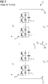
- phase module 400 In Figure 4 an embodiment of a phase module 400 according to the invention is shown. In addition to the first (positive-side) phase module branch 11 and the second (negative-side) phase module branch 13, this phase module 400 has a third (middle) phase module branch 404. A third voltage U S occurs at the third phase module branch 404.
- the phase module 400 is arranged between the first DC voltage connection 16 and the second DC voltage connection 17, the first phase module branch 11 being connected to the first DC voltage connection 16.
- the second phase module branch 13 is connected to the second DC voltage connection 17.
- Each phase module branch has a multiplicity of modules.
- the first phase module branch 11 has n modules 1_1...
- module 1_n each in a half-bridge circuit (half-bridge modules) or can be designed in full bridge circuit (full bridge modules).
- module 1_1 is shown as a full-bridge module and module 1_n as a half-bridge module.
- the second phase module branch 13 likewise has n modules 2_1 ... 2_n. each of which can be designed in a half-bridge circuit (half-bridge modules) or in a full-bridge circuit (full-bridge modules).
- the first phase module branch 11 and the second phase module branch 13 can therefore each have only half-bridge modules (or only full-bridge modules), for example.
- the third phase module branch 404 has at least one module 408_1 with a full bridge circuit (full bridge module 408_1), as well as further modules 408_2 to 408_n, each of which can be configured in a half bridge circuit (half bridge modules) or in a full bridge circuit (full bridge modules).
- the third phase module branch 404 connects the first phase module branch 11 to the second phase module branch 13 with the formation of a first connection point 412 between the first phase module branch 11 and the third phase module branch 404 and with the formation of a second connection point 416 between the third phase module branch 404 and the second phase module branch 13 420 is set up to electrically connect the first AC voltage connection 5 to the first connection point 412 in a first switching position 421, and to electrically connect the first AC voltage connection 5 to the second connection point 416 in a second switching position 422. Furthermore, the switching device 420 is set up to electrically separate the AC voltage connection 5 from the first connection point 412 in the second switching position 422 and to electrically separate the first AC voltage connection 5 from the second connection point 416 in the first switching position 421.
- the switching device 420 has, as switching elements, a first thyristor T1, a second thyristor T2, a third thyristor T3 and a fourth thyristor T4. More precisely, the switching device has a first electronic power switch 424 and a second electronic power switch 428.
- the first electronic power switch 424 has the first thyristor T1 and the second thyristor T2; the second electronic power switch 428 has the third thyristor T3 and the fourth thyristor T4.
- the first electronic power switch 424 thus has thyristors T1 and T2 connected in anti-parallel; the second electronic power switch 428 has thyristors T3 and T4 connected in anti-parallel.
- thyristors T1, T2, T3 and T4 are to be understood here only symbolically. In reality, for example, a larger number of thyristors can be connected in series and / or in parallel in order to achieve the required voltage and current values.
- the first electronic power switch 424 electrically connects the first AC voltage connection 5 to the first connection point 412; the first electronic power switch 424 electrically disconnects the first AC voltage connection 5 from the first connection point 412 in the second switching position of the switching device 420.
- the second electronic power switch 428 electrically connects the first AC voltage connection 5 to the second connection point 416; The second electronic power switch 428 electrically isolates the first AC voltage connection 5 from the second connection point 416 in the first switching position of the switching device 420.
- the switching device 420 assumes its switching positions (that is to say the first switching position and the second switching position) as a function of the instantaneous value of the alternating voltage applied to the alternating voltage connection 5. More precisely, the switching device 420 is controlled by a control device (not shown) in such a way that it assumes its switching positions (i.e. the first switching position and the second switching position) as a function of the instantaneous value of the alternating voltage applied to the alternating voltage connection 5. The switching device 420 then assumes the first switching position when the instantaneous value of the alternating voltage is greater than (or equal to) zero. The first AC voltage connection 5 is then electrically connected to the first connection point 412. The switching device 420 assumes the second switching position when the instantaneous value of the alternating voltage applied to the alternating voltage connection 5 is less than zero. The first AC voltage connection 5 is then electrically connected to the second connection point 416.
- the multilevel converter can also be set up in such a way that the switching device assumes the first switching position when the instantaneous value of the voltage applied to the AC voltage connection is in a first preselected voltage range, and the switching device assumes the second switching position when the instantaneous value of the voltage applied to the AC voltage connection is in a second preselected voltage range.
- the first preselected voltage range can be, for example, the voltage range between 0 and +1/2 U dc ;
- the second preselected voltage range can be the voltage range between -1/2 U dc and 0, for example.
- Each phase module branch 11, 13 and 404 therefore only needs to be designed for half the maximum direct voltage 1/2 U dc . In comparison to the previously known phase module 15 of the Figure 2 so fewer modules are required. 25% of the modules can be saved because the modules of the third phase module branch 404 are optionally assigned, so to speak, to the first phase module branch 11 or the third phase module branch 404 (this assumes that the same number of modules is present in each phase module branch).
- only the relatively low voltage U n is applied to the second phase module branch 13 while the larger voltage (U dc - U n ) is applied to the first phase module branch 11 and the second phase module branch 404.
- U dc - U n Analogously to the processes in the first half of the period of the alternating voltage, a maximum of 1/2 U dc occurs again on each phase module branch .
- phase module 400 is the Figure 4 shown again in a simplified representation.
- first phase module branch 11, the second phase module branch 13 and the third phase module branch 404 are each represented symbolically as a square with a diagonal drawn in.
- the first electronic power switch 424 and the second electronic power switch 428 are each shown as a smaller square with two diagonals drawn in.
- Figure 6 is also shown by means of voltage arrows, such as the alternating voltage U ac occurring at the first alternating voltage connection 5 with respect to the ground connection 202 during the first Half cycle of the alternating voltage (U ac > 0) occurs between the first connection point 412 and the ground connection 202.
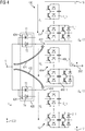
- FIG 7 a further embodiment of a phase module 700 is shown.
- the third phase module branch is divided into three sub-branches: a first sub-branch 704, a second sub-branch 708 and a third sub-branch 712.
- the first phase module branch 11 is electrically connected to the first sub-branch 704, forming the first connection point 412.
- the first sub-branch 704 is electrically connected to the second sub-branch 708, forming a third connection point 716.
- the second sub-branch 708 is electrically connected to the third sub-branch 712, forming a fourth connection point 720
- the third sub-branch 712 is electrically connected to the second phase module branch 13, forming the second connection point 416.
- a third electronic power switch 724 electrically connects (or disconnects) the third connection point 716 to the first AC connection 5.
- a fourth electronic power switch 728 electrically connects (or disconnects) the fourth connection point 720 to the first AC voltage connection 5.
- the switching device 732 has in addition to Figure 6 known first switching position and second switching position also a third switching position and a fourth switching position on. In the third switch position, the first AC voltage connection 5 is electrically connected to the third connection point 716 by means of the third power electronic switch 724 (and electrically separated from the connection points 412, 720 and 416 by means of the other power electronic switches 424, 728 and 428).
- the first AC voltage connection 5 is electrically connected to the fourth connection point 720 by means of the fourth power electronic switch 728 (and electrically separated from the connection points 412, 716 and 416 by means of the power electronic switches 424, 724 and 428).
- a voltage range of the alternating voltage is assigned to each power electronic switch 424, 724, 728 and 428. These voltage ranges are non-overlapping voltage ranges. If the instantaneous value of the voltage applied to the AC voltage connection 5 is in one of the voltage ranges, the associated power electronic switch closes and connects the first AC voltage connection 5 to the respective connection point. The AC voltage connection 5 is then electrically separated from the other connection points.
- the first preselected voltage range can be, for example, the voltage range between +1/4 U dc and +1/2 U dc ;
- the second preselected voltage range can be, for example, the voltage range between 0 and +1/4 U dc ;
- the third preselected voltage range can be, for example, the voltage range between -1/4 U dc and 0;
- the fourth preselected voltage range can be, for example, the voltage range between -1/2 U dc and -1/4 U dc .
- the phase module 700 enables an even more flexible assignment of the modules of the individual sub-branches to the first phase module branch 11 or to the second phase module branch 13 first phase module branch 11 or the second phase module branch 13 are connected.
- FIG. 8 an embodiment of a multilevel converter 800 is shown.
- This three-phase multilevel converter 800 has three phase modules according to FIG Figure 6 on.
- FIG 9 an embodiment of a module 900 of the multilevel converter is shown. This can be, for example, one of the modules in the Figures 4 or 7th act shown phase modules.
- the module 900 is designed as a half-bridge module 900.
- the module 900 has a first electronic switching element 902 (which can be switched off) (first semiconductor valve 902 which can be switched off) with a first diode 904 connected in anti-parallel.
- the module 900 has a second (switchable) electronic switching element 906 (second switchable semiconductor valve 906) with a second diode 908 connected in anti-parallel and an electrical energy store 910 in the form of a capacitor 910.
- the first electronic switching element 902 and the second electronic switching element 906 are each designed as an IGBT (insulated-gate bipolar transistor).
- the first electronic switching element 902 is electrically connected in series with the second electronic switching element 906.
- a first galvanic module connection 912 is arranged at the connection point between the two electronic switching elements 902 and 906.
- a second galvanic module connection 915 is arranged at the connection of the second electronic switching element 906, which is opposite the connection point.
- the second module connection 915 is also electrically connected to a first connection of the energy store 910; a second connection of the energy store 910 is electrically connected to the Connection of the first electronic switching element 902, which is opposite the connection point.
- the energy store 910 is thus electrically connected in parallel to the series connection of the first electronic switching element 902 and the second electronic switching element 906.
- an electronic control device (not shown) of the converter can be achieved be that between the first module connection 912 and the second module connection 915 either the voltage of the energy store 910 is output or no voltage is output (ie a zero voltage is output).
- the respective desired output voltage of the converter can be generated.
- a further embodiment of a module 1000 of the multilevel converter is shown.
- This module 301 can be, for example, the module 408 1 of the in Figure 4 phase module 400 shown (or one of the other modules of the multilevel converter) act.
- first electronic switching element 902, second electronic switching element 906, first free-wheeling diode 904, second free-wheeling diode 908 and energy store 910 has the in Figure 10
- Module 1000 shown has a third electronic switching element 1002 with a third free-wheeling diode 1004 connected in anti-parallel and a fourth electronic switching element 1006 with a fourth free-wheeling diode 1008 connected in anti-parallel.
- the third electronic switching element 1002 and the fourth electronic switching element 1006 are each designed as an IGBT.
- the second module connection 1015 is not electrically connected to the second electronic switching element 906, but to a midpoint of an electrical series circuit from the third electronic switching element 1002 and the fourth electronic switching element 1006.
- the module 1000 of the Figure 10 is a so-called full bridge module 1000.
- This full bridge module 1000 is characterized by the fact that, with appropriate control of the four electronic switching elements between the first (galvanic) module connection 912 and the second (galvanic) module connection 1015, either the positive voltage of the energy store 910 , the negative voltage of the energy store 910 or a voltage of the value zero (zero voltage) can be output.
- the polarity of the output voltage can thus be reversed by means of the full bridge module 1000.
- the multilevel converter can either have only half-bridge modules 900, only full-bridge modules 1000 or also half-bridge modules 900 and full-bridge modules 1000.
- FIG. 11 an exemplary embodiment of a high-voltage direct current transmission system 1100 is shown schematically.
- This high-voltage direct current transmission system 1100 has two power converters 800, as shown in FIG Figure 8 are shown. These two converters 800 are electrically connected to one another on the DC voltage side via a high-voltage DC connection 1105.
- the two positive DC voltage connections 16 of the converters 800 are electrically connected to one another by means of a first high-voltage DC line 1105a; the two negative direct voltage connections 17 of the two power converters 800 are electrically connected to one another by means of a second high-voltage direct current line 1105b.
- the instantaneous value of the voltage present at the AC voltage connection 5 of the multilevel converter is thus measured.
- the AC voltage connection 5 is then electrically connected to the first connection point 412 or the second connection point 416 (or optionally one of the further connection points such as the third connection point 716 or the fourth connection point 720).
- the AC voltage connection 5 is in each case electrically connected to only one of the connection points; the AC voltage connection 5 is electrically separated from the other connection points by means of the other power electronic conductors.
- the AC voltage connection 5 is then electrically connected to the first connection point 412 when the instantaneous value of the voltage applied to the AC voltage connection 5 is greater than (or equal to) zero.
- the AC voltage connection 5 is then electrically connected to the second connection point 416 when the instantaneous value of the voltage applied to the AC voltage connection is less than zero.
- the AC voltage connection 5 is electrically connected to the connection point in each case by means of the switching device 732, in its assigned preselected voltage range the Instantaneous value of the alternating voltage U ac (present at the alternating voltage connection 5).
- the AC voltage connection 5 is electrically separated from the other connection points.
- the switching device 420, 732 can also be used particularly advantageously to clear errors when errors occur. If, for example, in a multilevel converter with phase modules 400 according to Figure 4 If a short circuit occurs on the DC voltage side, the switching device 420 can be brought into a special switching position (which is to be called the fault switching position here), in which the switching device electrically isolates the first AC voltage connection 5 from all connection points 412, 416 of the phase module. As a result, the flow of energy from the AC voltage network connected to the AC voltage connection of the converter is interrupted at the point of the DC voltage-side fault. This electrical interruption / disconnection can take place very quickly.
- the transition to the fault switching position can be done simply by switching off the control signals for the thyristors, whereupon the thyristors switch to their blocking position at the next zero crossing of the alternating voltage. This enables the alternating current to be switched off very quickly.
- a multilevel converter and a method for operating the multilevel converter have been described in which, compared to a conventional multilevel converter, a smaller number of modules is sufficient. As a result, costs and installation space can be saved and the power loss occurring in the switching elements of the modules can be reduced.
- phase module branch forms a positive-side phase module branch
- second phase module branch a negative-side phase module branch
- third phase module branch a middle phase module branch.
- the anti-parallel thyristor valves make it possible to limit the voltage provided by a phase module branch from 100% U dc to 50% U dc. This reduces the necessary power converter output from two times 100% to three times 50%. This corresponds to a saving of 25% required power. This can result in a saving of 25% of the required modules.
- the firing pulse of the thyristors is switched off.
- the thyristors then block, so that the flowing alternating current quickly approaches zero. This takes place within a few milliseconds.
- a Conventional AC-side circuit breaker Switching times between approx. 2.5 to 3 periods, i.e. between approx. 50 ms to 60 ms at an alternating current frequency of 50 Hz. Using the switching device described, the error can therefore be cleared much faster than with a conventional AC-side AC -Circuit breaker.
- the thyristors Compared to the modules with IGBT switching elements, the thyristors also have significantly lower on-state losses (a smaller loss per component), higher blocking voltages (require a lower number of series connections to achieve the same voltage) and thus lower costs. The additional expense for the additional thyristor valves is more than compensated for by the savings in the modules.
- the described multilevel converter and the described method can be used for a wide variety of system types, for example for high-voltage direct current transmission by means of underground cables or overhead lines.
Description
Die Erfindung betrifft einen Multilevelstromrichter mit einem Phasenmodul, welches zwischen einem ersten Gleichspannungsanschluss und einem zweiten Gleichspannungsanschluss des Multilevelstromrichters angeordnet ist und welches eine Vielzahl von Modulen aufweist, wobei das Phasenmodul einen ersten Phasenmodulzweig aufweist, der mit dem ersten Gleichspannungsanschluss verbunden ist, und einen zweiten Phasenmodulzweig aufweist, der mit dem zweiten Gleichspannungsanschluss verbunden ist, und wobei die Module jeweils mindestens zwei elektronische Schaltelemente und einen elektrischen Energiespeicher aufweisen, und wobei der Multilevelstromrichter drei derartige Phasenmodule aufweist.The invention relates to a multilevel converter with a phase module which is arranged between a first DC voltage connection and a second DC voltage connection of the multilevel converter and which has a plurality of modules, the phase module having a first phase module branch which is connected to the first DC voltage connection and a second phase module branch which is connected to the second DC voltage connection, and wherein the modules each have at least two electronic switching elements and an electrical energy store, and wherein the multilevel converter has three such phase modules.
Weiterhin betrifft die Erfindung ein Verfahren zum Betreiben eines Multilevelstromrichters. Ein Multilevelstromrichter (der auch als modularer Multilevelstromrichter bezeichnet wird) ist eine leistungselektronische Schaltung zum Umwandeln von elektrischer Energie. Mit einem Multilevelstromrichter kann beispielsweise Wechselstrom in Gleichstrom oder Gleichstrom in Wechselstrom umgewandelt werden. Ein Multilevelstromrichter weist eine Vielzahl von gleichartigen Modulen auf, welche elektrisch in Reihe geschaltet sind. Durch die elektrische Reihenschaltung der Module lassen sich hohe Ausgangsspannungen erreichen. Ein Multilevelstromrichter ist einfach an unterschiedliche Spannungen anpassbar (skalierbar) und eine gewünschte Ausgangsspannung kann relativ genau erzeugt werden. Ein Multilevelstromrichter kann vorteilhafterweise im Hochspannungsbereich eingesetzt werden, beispielsweise als Stromrichter bei einer Hochspannungs-Gleichstrom-Übertragungsanlage oder als Blindleistungskompensationsanlage.The invention also relates to a method for operating a multilevel converter. A multilevel converter (also known as a modular multilevel converter) is a power electronic circuit for converting electrical energy. With a multilevel converter, for example, alternating current can be converted into direct current or direct current into alternating current. A multilevel converter has a large number of modules of the same type, which are electrically connected in series. The electrical series connection of the modules enables high output voltages to be achieved. A multilevel converter can be easily adapted (scaled) to different voltages and a desired output voltage can be generated relatively precisely. A multilevel converter can advantageously be used in the high-voltage range, for example as a converter in a high-voltage direct current transmission system or as a reactive power compensation system.
Die Anzahl der Module in der elektrischen Reihenschaltung ist so zu wählen, dass der Multilevelstromrichter die benötigte Ausgangsspannung erzeugen kann. Außerdem muss die Anzahl der Module in der Reihenschaltung aber auch so groß sein, dass bei allen Betriebszuständen des Multilevelstromrichters die an den Modulen anliegende Spannung die maximal zulässige Modulspannung nicht überschreitet. Daher müssen mehr Module in der Reihenschaltung vorhanden sein, als zum Erzeugen einer vorgegebenen Ausgangsspannung notwendig wären. Dies verursacht hohe Kosten, hohe Verlustleistungen und eine große Bauform des Multilevelstromrichters.The number of modules in the electrical series connection must be selected so that the multilevel converter can generate the required output voltage. In addition, the number of modules in the series connection must be large enough that the voltage applied to the modules does not exceed the maximum permissible module voltage in all operating states of the multilevel converter. Therefore, there must be more modules in the series connection than would be necessary to generate a given output voltage. This causes high costs, high power losses and a large design of the multilevel converter.
Der Erfindung liegt die Aufgabe zugrunde, einen Multilevelstromrichter und ein Verfahren anzugeben, bei denen die Anzahl der Module reduziert werden kann.The invention is based on the object of specifying a multilevel converter and a method in which the number of modules can be reduced.
Diese Aufgabe wird erfindungsgemäß gelöst durch einen Multilevelstromrichter und durch ein Verfahren nach den unabhängigen Patentansprüchen. Vorteilhafte Ausführungsformen des Multilevelstromrichters und des Verfahrens sind in den abhängigen Patentansprüchen angegeben.This object is achieved according to the invention by a multilevel converter and by a method according to the independent claims. Advantageous embodiments of the multilevel converter and the method are specified in the dependent claims.
Offenbart wird ein Multilevelstromrichter mit einem Phasenmodul, welches zwischen einem ersten Gleichspannungsanschluss und einem zweiten Gleichspannungsanschluss des Multilevelstromrichters angeordnet ist und welches eine Vielzahl von Modulen aufweist, wobei das Phasenmodul einen ersten Phasenmodulzweig aufweist, der mit dem ersten Gleichspannungsanschluss verbunden ist, und einen zweiten Phasenmodulzweig aufweist, der mit dem zweiten Gleichspannungsanschluss verbunden ist, und wobei die Module jeweils mindestens zwei elektronische Schaltelemente und einen elektrischen Energiespeicher aufweisen, und wobei der Multilevelstromrichter drei derartige Phasenmodule aufweist.A multilevel converter is disclosed with a phase module which is arranged between a first direct voltage connection and a second direct voltage connection of the multilevel converter and which has a plurality of modules, the phase module having a first phase module branch which is connected to the first direct voltage connection and a second phase module branch , which is connected to the second DC voltage connection, and wherein the modules each have at least two electronic switching elements and an electrical energy store, and wherein the multilevel converter has three such phase modules.
Der Multilevelstromrichter weist einen dritten Phasenmodulzweig auf, der den ersten Phasenmodulzweig mit dem zweiten Phasenmodulzweig verbindet, und eine Schalteinrichtung, welche in einer ersten Schaltstellung einen Wechselspannungsanschluss des Multilevelstromrichters mit einem ersten Verbindungspunkt zwischen dem ersten Phasenmodulzweig und dem dritten Phasenmodulzweig (elektrisch) verbindet und in einer zweiten Schaltstellung den Wechselspannungsanschluss mit einem zweiten Verbindungspunkt zwischen dem dritten Phasenmodulzweig und dem zweiten Phasenmodulzweig (elektrisch) verbindet. Mit anderen Worten gesagt, ist die Schalteinrichtung dazu eingerichtet, in einer ersten Schaltstellung einen Wechselspannungsanschluss des Multilevelstromrichters mit einem ersten Verbindungspunkt zwischen dem ersten Phasenmodulzweig und dem dritten Phasenmodulzweig (elektrisch) zu verbinden und in einer zweiten Schaltstellung den Wechselspannungsanschluss mit einem zweiten Verbindungspunkt zwischen dem dritten Phasenmodulzweig und dem zweiten Phasenmodulzweig (elektrisch) zu verbinden. Der erste Verbindungspunkt ist der (gemeinsame) Verbindungspunkt von dem ersten Phasenmodulzweig und dem dritten Phasenmodulzweig. Der erste Verbindungspunkt ist also der Punkt, an dem der erste Phasenmodulzweig elektrisch mit dem dritten Phasenmodulzweig verbunden ist. Der zweite Verbindungspunkt ist der (gemeinsame) Verbindungspunkt von dem dritten Phasenmodulzweig und dem zweiten Phasenmodulzweig. Der zweite Verbindungspunkt ist also der Punkt, an dem der dritte Phasenmodulzweig elektrisch mit dem zweiten Phasenmodulzweig verbunden ist.The multilevel converter has a third phase module branch, which connects the first phase module branch to the second phase module branch, and a switching device which, in a first switching position connects an AC voltage connection of the multilevel converter to a first connection point between the first phase module branch and the third phase module branch (electrically) and, in a second switching position, connects the AC voltage connection to a second connection point between the third phase module branch and the second phase module branch (electrically). In other words, the switching device is set up to (electrically) connect an AC voltage connection of the multilevel converter to a first connection point between the first phase module branch and the third phase module branch in a first switching position and the AC voltage connection to a second connection point between the third To connect phase module branch and the second phase module branch (electrically). The first connection point is the (common) connection point of the first phase module branch and the third phase module branch. The first connection point is therefore the point at which the first phase module branch is electrically connected to the third phase module branch. The second connection point is the (common) connection point of the third phase module branch and the second phase module branch. The second connection point is therefore the point at which the third phase module branch is electrically connected to the second phase module branch.
Dabei ist besonders vorteilhaft, dass die Schalteinrichtung den Wechselspannungsanschluss des Multilevelstromrichters entweder mit dem ersten Verbindungspunkt oder mit dem zweiten Verbindungspunkt elektrisch verbindet. Dadurch kann die Anzahl der Module zwischen dem Wechselspannungsanschluss und dem ersten Gleichspannungsanschluss nach Bedarf um die Anzahl der Module des dritten Phasenmodulzweigs vergrößert oder verkleinert werden. Ebenso kann die Anzahl der Module zwischen dem Wechselspannungsanschluss und dem zweiten Gleichspannungsanschluss um die Anzahl der Module des dritten Phasenmodulzweigs vergrößert oder verkleinert werden. Mit anderen Worten gesagt, können also die Module des dritten Phasenmodulzweigs bedarfsweise dem ersten Phasenmodulzweig oder dem zweiten Phasenmodulzweig zugeordnet werden. Diese Module des dritten Phasenmodulzweigs haben also eine Doppelfunktion. Je nach Schaltstellung der Schalteinrichtung werden diese Module zwischen den Wechselspannungsanschluss des Multilevelstromrichters und den ersten Gleichspannungsanschluss geschaltet oder zwischen den Wechselspannungsanschluss und den zweiten Gleichspannungsanschluss geschaltet. Die Module des dritten Phasenmodulzweigs werden also zum Erzeugen verschiedener Spannungen des Multilevelstromrichters eingesetzt. Durch die Möglichkeit der Umschaltung zwischen der ersten Schaltstellung und der zweiten Schaltstellung brauchen die Module des dritten Phasenmodulzweiges nur einmal vorhanden zu sein. (Bei dem bisher bekannten Multilevelstromrichter müssen die Module zweimal vorhanden, nämlich einmal im dem ersten (positivseitigen) Phasenmodulzweig im einmal in dem zweiten (negativseitigen) Phasenmodulzweig.) Dadurch kann die Anzahl der benötigten Module pro Phasenmodul deutlich verringert werden. Dies führt auch zu einer deutlichen Verringerung der Größe des Multilevelstromrichters, der Stromrichterverluste und der Kosten. Es ist möglich, 25 % der benötigten Module einzusparen. Außerdem kann mittels der Schalteinrichtung eine schnelle Fehlerklärung realisiert werden. Auch wenn der Begriff "Schaltstellung" verwendet wird, bedeutet dies nicht, dass die Schalteinrichtung notwendigerweise eine mechanische Schalteinrichtung sein muss. Vielmehr ist vorteilhafterweise vorgesehen, dass die Schalteinrichtung eine leistungselektronische Schalteinrichtung sein kann, siehe unten.It is particularly advantageous that the switching device electrically connects the AC voltage connection of the multilevel converter either to the first connection point or to the second connection point. As a result, the number of modules between the AC voltage connection and the first DC voltage connection can be increased or decreased as required by the number of modules in the third phase module branch. Likewise, the number of modules between the AC voltage connection and the second DC voltage connection can be increased by the number of modules of the third Phase module branch can be enlarged or reduced. In other words, the modules of the third phase module branch can be assigned to the first phase module branch or the second phase module branch as required. These modules of the third phase module branch thus have a double function. Depending on the switching position of the switching device, these modules are connected between the AC voltage connection of the multilevel converter and the first DC voltage connection or between the AC voltage connection and the second DC voltage connection. The modules of the third phase module branch are therefore used to generate different voltages for the multilevel converter. Due to the possibility of switching between the first switching position and the second switching position, the modules of the third phase module branch only need to be present once. (In the previously known multilevel converter, the modules must be present twice, namely once in the first (positive-side) phase module branch and once in the second (negative-side) phase module branch.) This can significantly reduce the number of modules required per phase module. This also leads to a significant reduction in the size of the multilevel converter, the converter losses and the costs. It is possible to save 25% of the required modules. In addition, the switching device can be used to quickly clear errors. Even if the term "switching position" is used, this does not mean that the switching device must necessarily be a mechanical switching device. Rather, it is advantageously provided that the switching device can be a power electronic switching device, see below.
Der Multilevelstromrichter kann so ausgestaltet sein, dass die Schalteinrichtung in der zweiten Schaltstellung den Wechselspannungsanschluss des Multilevelstromrichters von dem ersten Verbindungspunkt (elektrisch) trennt und in der ersten Schaltstellung den Wechselspannungsanschluss von dem zweiten Verbindungspunkt (elektrisch) trennt. Allgemein gesagt, verbindet die Schalteinrichtung den Wechselspannungsanschluss in jeder Schaltstellung jeweils nur maximal mit einem (der Schaltstellung zugehörigen) Verbindungspunkt (und trennt den Wechselspannungsanschluss von den jeweils anderen Verbindungspunkten.) Die Schalteinrichtung verbindet also (in ihren Schaltstellungen) den Wechselspannungsanschluss jeweils exklusiv mit einem (der Schaltstellung zugehörigen) Verbindungspunkt. Natürlich kann es auch eine Schaltstellung geben, in der der Wechselspannungsanschluss von allen Verbindungspunkten getrennt ist.The multilevel converter can be designed so that the switching device (electrically) disconnects the AC voltage connection of the multilevel converter from the first connection point in the second switch position and the AC voltage connection from the second in the first switch position Connection point (electrical) separates. Generally speaking, the switching device connects the AC voltage connection in each switching position only to a maximum of one connection point (belonging to the switching position) (and separates the AC voltage connection from the other connection points.) The switching device therefore connects (in its switching positions) the AC voltage connection exclusively to one ( the connection point associated with the switch position. Of course, there can also be a switch position in which the AC voltage connection is separated from all connection points.
Der Multilevelstromrichter kann auch so ausgestaltet sein, dass der erste Phasenmodulzweig, der zweite Phasenmodulzweig und der dritte Phasenmodulzweig jeweils mindestens zwei der Module, insbesondere jeweils mindestens fünf der Module, in einer Reihenschaltung aufweisen.The multilevel converter can also be designed such that the first phase module branch, the second phase module branch and the third phase module branch each have at least two of the modules, in particular at least five of the modules, in a series connection.
Der Multilevelstromrichter kann auch so ausgestaltet sein, dass die Schalteinrichtung (als Schaltelemente) Thyristoren aufweist. Mittels Thyristoren lässt sich die Umschaltung zwischen dem ersten Verbindungspunkt und dem zweiten Verbindungspunkt besonders schnell durchführen.The multilevel converter can also be designed in such a way that the switching device (as switching elements) has thyristors. Switching between the first connection point and the second connection point can be carried out particularly quickly by means of thyristors.
Der Multilevelstromrichter kann auch so ausgestaltet sein, dass
- die Schalteinrichtung einen ersten leistungselektronischen Schalter aufweist, der bei der ersten Schaltstellung der Schalteinrichtung den Wechselspannungsanschluss mit dem ersten Verbindungspunkt (elektrisch) verbindet und bei der zweiten Schaltstellung der Schalteinrichtung den Wechselspannungsanschluss von dem ersten Verbindungspunkt (elektrisch) trennt und
- die Schalteinrichtung einen zweiten leistungselektronischen Schalter aufweist, der bei der zweiten Schaltstellung der Schalteinrichtung den Wechselspannungsanschluss mit dem zweiten Verbindungspunkt (elektrisch) verbindet und bei der ersten Schaltstellung der Schalteinrichtung den Wechselspannungsanschluss von dem zweiten Verbindungspunkt (elektrisch) trennt. Mit den beiden leistungselektronischen Schaltern der Schalteinrichtung lässt sich die Umschaltung zwischen dem ersten Verbindungspunkt und dem zweiten Verbindungspunkt besonders einfach und schnell durchführen.
- the switching device has a first power electronic switch which connects the AC voltage connection to the first connection point (electrically) in the first switching position of the switching device and (electrically) separates the AC voltage connection from the first connection point in the second switching position of the switching device and
- the switching device has a second electronic power switch which, in the second switching position of the switching device, connects the AC voltage connection to the second connection point (electrically) and in the first switching position of the switching device separates the AC voltage connection from the second connection point (electrically). With the two power electronic switches of the switching device, switching between the first connection point and the second connection point can be carried out particularly easily and quickly.
Der Multilevelstromrichter kann so ausgestaltet sein, dass der erste leistungselektronische Schalter und der zweite leistungselektronische Schalter jeweils Thyristoren aufweisen.The multilevel converter can be designed in such a way that the first electronic power switch and the second electronic power switch each have thyristors.
Der Multilevelstromrichter kann auch so ausgestaltet sein, dass der erste leistungselektronische Schalter und der zweite leistungselektronische Schalter jeweils antiparallel geschaltete Thyristoren aufweisen. Dadurch können die leistungselektronischen Schalter den durch den Wechselspannungsanschluss fließenden Wechselstrom mit beiden Polaritäten schalten.The multilevel converter can also be designed in such a way that the first electronic power switch and the second electronic power switch each have thyristors connected in anti-parallel. As a result, the power electronic switches can switch the alternating current flowing through the alternating voltage connection with both polarities.
Der Multilevelstromrichter kann so ausgestaltet sein, dass mindestens ein Modul des dritten Phasenmodulzweigs so ausgestaltet ist, dass es eine Spannung positiver oder negativer Polarität auszugeben imstande ist. Dies unterstützt vorteilhafterweise insbesondere den Abschaltvorgang der Thyristoren. Dabei ist besonders vorteilhaft, dass das mindestens eine Modul in der Lage ist, sowohl eine negative Spannung als auch eine positive Spannung zu erzeugen und auszugeben. Mittels dieser Spannung lässt sich die Kommutierung des über den Wechselspannungsanschluss fließenden Stroms von dem ersten Verbindungspunkt zu dem zweiten Verbindungspunkt sicher und zuverlässig realisieren. Dies kann beispielsweise dadurch erfolgen, dass mittels des Moduls eine dem ursprünglichen Stromfluss entgegengerichtete Spannung als Kommutierungsspannung erzeugt wird.The multilevel converter can be designed such that at least one module of the third phase module branch is designed such that it is able to output a voltage of positive or negative polarity. This advantageously supports the switching off process of the thyristors in particular. It is particularly advantageous that the at least one module is able to generate and output both a negative voltage and a positive voltage. By means of this voltage, the commutation of the current flowing via the AC voltage connection from the first connection point to the second connection point can be implemented safely and reliably. This can be done, for example, by using the module to generate a voltage opposite to the original current flow as a commutation voltage.
Der Multilevelstromrichter kann so ausgestaltet sein, dass mindestens ein Modul des dritten Phasenmodulzweigs eine Vollbrückenschaltung aufweist. Dabei ist besonders vorteilhaft, dass das mindestens eine Modul mit Vollbrückenschaltung in der Lage ist, sowohl eine negative Spannung als auch eine positive Spannung zu erzeugen und auszugeben. Dies unterstützt die Kommutierung, wie vorstehend angegeben ist.The multilevel converter can be designed such that at least one module of the third phase module branch has a full bridge circuit. It is particularly advantageous that the at least one module with a full bridge circuit is able to generate and output both a negative voltage and a positive voltage. This supports the commutation, as indicated above.
Der Multilevelstromrichter kann so ausgestaltet sein, dass die Vollbrückenschaltung vier elektronische Schaltelemente und einen elektrischen Energiespeicher aufweist.The multilevel converter can be designed in such a way that the full bridge circuit has four electronic switching elements and an electrical energy store.
Der Multilevelstromrichter kann auch so ausgestaltet sein, dass der dritte Phasenmodulzweig mehrere elektrisch in Reihe geschaltete Teilzweige aufweist, und die Schalteinrichtung eine dritte Schaltstellung aufweist, bei der der Wechselspannungsanschluss mit einem dritten Verbindungspunkt zweier Teilzweige verbunden ist (und bei der der Wechselspannungsanschluss von dem ersten Verbindungspunkt und dem zweiten Verbindungspunkt (elektrisch) getrennt ist). Dieser Multilevelstromrichter weist weitere Verbindungspunkte (Potenzialpunkte) auf, mit denen der Wechselspannungsanschluss mittels der Schalteinrichtung verbunden werden kann.The multilevel converter can also be designed so that the third phase module branch has several sub-branches electrically connected in series, and the switching device has a third switching position in which the AC voltage connection is connected to a third connection point of two sub-branches (and in which the AC voltage connection is connected to the first connection point and the second connection point is (electrically) separated). This multilevel converter has further connection points (potential points) to which the AC voltage connection can be connected by means of the switching device.
Der Multilevelstromrichter kann auch so ausgestaltet sein, dass die Schalteinrichtung die Schaltstellungen (, insbesondere die erste Schaltstellung und die zweite Schaltstellung,) in Abhängigkeit von dem Augenblickswert der an dem Wechselspannungsanschluss anliegenden Spannung (Wechselspannung) einnimmt. Vorteilhafterweise kann die Schalteinrichtung so angesteuert werden, dass sie die Schaltstellungen in Abhängigkeit von dem Augenblickswert der an den Wechselspannungsanschluss anliegenden Spannung (Wechselspannung) einnimmt. Dadurch ergibt sich eine besonders einfache Art der Ansteuerung der Schalteinrichtung.The multilevel converter can also be designed in such a way that the switching device assumes the switching positions (in particular the first switching position and the second switching position) as a function of the instantaneous value of the voltage (AC voltage) applied to the AC voltage connection. The switching device can advantageously be controlled in such a way that it assumes the switching positions as a function of the instantaneous value of the voltage (alternating voltage) applied to the alternating voltage connection. This results in a particularly simple type of control of the switching device.
Es braucht lediglich der Augenblickswert der Wechselspannung ausgewertet zu werden und in Abhängigkeit von der Höhe des Augenblickswertes nimmt die Schalteinrichtung die jeweilige Schaltstellung (insbesondere die erste Schaltstellung und die zweite Schaltstellung) ein.Only the instantaneous value of the alternating voltage needs to be evaluated and depending on the magnitude of the instantaneous value, the switching device assumes the respective switch position (in particular the first switch position and the second switch position).
Der Multilevelstromrichter kann auch so ausgestaltet sein, dass
- die Schalteinrichtung die erste Schaltstellung einnimmt, wenn der Augenblickswert der an dem Wechselspannungsanschluss anliegenden Spannung größer (oder gleich) Null ist, und die Schalteinrichtung die zweite Schaltstellung einnimmt, wenn der Augenblickswert der an dem Wechselspannungsanschluss anliegenden Spannung kleiner Null ist, oder
- die Schalteinrichtung die erste Schaltstellung einnimmt, wenn der Augenblickswert der an dem Wechselspannungsanschluss anliegenden Spannung in einem ersten vorgewählten Spannungsbereich liegt, und die Schalteinrichtung die zweite Schaltstellung einnimmt, wenn der Augenblickswert der an dem Wechselspannungsanschluss anliegenden Spannung in einem zweiten vorgewählten Spannungsbereich liegt. Die erste Alternative bildet vorteilhafterweise eine besonders einfache Möglichkeit festzulegen, wann die Schalteinrichtung die erste Schaltstellung und wann sie die zweite Schaltstellung einnimmt: wenn der Augenblickswert der Wechselspannung größer (oder gleich) null ist wird die erste Schaltstellung eingenommen; wenn der Augenblickswert der Wechselspannung kleiner null ist, wird die zweite Schaltstellung eingenommen. Die zweite Alternative gibt an, dass die erste Schaltstellung eingenommen wird, wenn der Augenblickswert der Wechselspannung in einem ersten vorgewählten Spannungsbereich liegt. Wenn der Augenblickswert in einem zweiten vorgewählten Spannungsbereich liegt, dann wird die zweite Schaltstellung eingenommen. Diese Variante ermöglicht ein noch flexibleres Schalten der Schalteinrichtung.
- the switching device assumes the first switching position when the instantaneous value of the voltage applied to the AC voltage connection is greater than (or equal to) zero, and the switching device assumes the second switching position when the instantaneous value of the voltage applied to the AC voltage connection is less than zero, or
- the switching device assumes the first switching position when the instantaneous value of the voltage applied to the AC voltage connection is in a first preselected voltage range, and the switching device adopts the second switching position when the instantaneous value of the voltage applied to the AC voltage connection is in a second preselected voltage range. The first alternative advantageously forms a particularly simple possibility of determining when the switching device assumes the first switching position and when it assumes the second switching position: if the instantaneous value of the alternating voltage is greater than (or equal to) zero, the first switching position is adopted; when the instantaneous value of the alternating voltage is less than zero, the second switch position is assumed. The second alternative indicates that the first switching position is assumed when the instantaneous value of the alternating voltage is in a first preselected voltage range. If the instantaneous value is in a second preselected voltage range, the second switch position is adopted. This variant enables the switching device to be switched even more flexibly.
Offenbart wird weiterhin eine Hochspannungs-Gleichstrom-Übertragungsanlage mit einem Stromrichter gemäß den vorstehend beschriebenen Varianten.A high-voltage direct current transmission system with a converter according to the variants described above is also disclosed.
Offenbart wird weiterhin ein Verfahren zum Betreiben eines Multilevelstromrichters mit mindestens einem Phasenmodul, welches zwischen einem ersten Gleichspannungsanschluss und einem zweiten Gleichspannungsanschluss des Multilevelstromrichters angeordnet ist und welches eine Vielzahl von Modulen aufweist, wobei das Phasenmodul einen ersten Phasenmodulzweig aufweist, der mit dem ersten Gleichspannungsanschluss verbunden ist, einen zweiten Phasenmodulzweig aufweist, der mit dem zweiten Gleichspannungsanschluss verbunden ist,
und einen dritten Phasenmodulzweig aufweist, der den ersten Phasenmodulzweig mit dem zweiten Phasenmodulzweig verbindet, wobei bei dem Verfahren
- ein Augenblickswert der an einem Wechselspannungsanschluss des Multilevelstromrichters anliegenden Spannung gemessen wird, und
- in Abhängigkeit von dem gemessenen Augenblickswert der Wechselspannungsanschluss mit einem ersten Verbindungspunkt zwischen dem ersten Phasenmodulzweig und dem dritten Phasenmodulzweig oder mit einem zweiten Verbindungspunkt zwischen dem dritten Phasenmodulzweig und dem zweiten Phasenmodulzweig (elektrisch) verbunden wird.
and a third phase module branch which connects the first phase module branch to the second phase module branch, wherein in the method
- an instantaneous value of the voltage present at an AC voltage connection of the multilevel converter is measured, and
- Depending on the measured instantaneous value, the AC voltage connection is (electrically) connected to a first connection point between the first phase module branch and the third phase module branch or to a second connection point between the third phase module branch and the second phase module branch.
Das Verfahren kann so ablaufen, dass
- der Wechselspannungsanschluss mit dem ersten Verbindungspunkt oder dem zweiten Verbindungspunkt (elektrisch) verbunden wird mittels einer Schalteinrichtung, die mindestens einen leistungselektronischen Schalter aufweist.
- the AC voltage connection is (electrically) connected to the first connection point or the second connection point by means of a switching device which has at least one power electronic switch.
Das Verfahren kann auch so ablaufen, dass
- mittels einer Schalteinrichtung in deren ersten Schaltstellung der Wechselspannungsanschluss mit dem ersten Verbindungspunkt(elektrisch) verbunden wird und der Wechselspannungsanschluss von dem zweiten Verbindungspunkt (elektrisch) getrennt wird, und
- mittels der Schalteinrichtung in deren zweiten Schaltstellung der Wechselspannungsanschluss mit dem zweiten Verbindungspunkt (elektrisch) verbunden wird und der Wechselspannungsanschluss von dem ersten Verbindungspunkt (elektrisch) getrennt wird.
- the AC voltage connection to the first by means of a switching device in its first switching position Connection point is (electrically) connected and the AC voltage connection is separated from the second connection point (electrically), and
- by means of the switching device in its second switching position, the AC voltage connection is connected to the second connection point (electrically) and the AC voltage connection is separated from the first connection point (electrically).
Das Verfahren kann so ablaufen, dass
- der Wechselspannungsanschluss mit dem ersten Verbindungspunkt (elektrisch) verbunden wird, wenn der Augenblickswert der an dem Wechselspannungsanschluss anliegenden Spannung größer (oder gleich) Null ist, und der Wechselspannungsanschluss mit dem zweiten Verbindungspunkt (elektrisch) verbunden wird, wenn der Augenblickswert der an dem Wechselspannungsanschluss anliegenden Spannung kleiner Null ist, oder
- der Wechselspannungsanschluss mit dem ersten Verbindungspunkt (elektrisch) verbunden wird, wenn der Augenblickswert der an dem Wechselspannungsanschluss anliegenden Spannung in einem ersten vorgewählten Spannungsbereich liegt und der Wechselspannungsanschluss mit dem zweiten Verbindungspunkt (elektrisch) verbunden wird, wenn der Augenblickswert der an dem Wechselspannungsanschluss anliegenden Spannung in einem zweiten vorgewählten Spannungsbereich liegt.
- the AC voltage connection is (electrically) connected to the first connection point if the instantaneous value of the voltage applied to the AC voltage connection is greater than (or equal to) zero, and the AC voltage connection is connected (electrically) to the second connection point if the instantaneous value is applied to the AC voltage connection Voltage is less than zero, or
- the AC voltage connection is (electrically) connected to the first connection point if the instantaneous value of the voltage applied to the AC voltage connection is in a first preselected voltage range and the AC voltage connection is connected (electrically) to the second connection point if the instantaneous value of the voltage applied to the AC voltage connection is in a second preselected voltage range.
Das Verfahren kann auch so ablaufen, dass
- der dritte Phasenmodulzweig mehrere elektrisch in Reihe geschaltete Teilzweige aufweist, zwischen denen mindestens ein weiterer Verbindungspunkt besteht, wobei in Abhängigkeit von dem gemessenen Augenblickswert (der an dem Wechselspannungsanschluss des Multilevelstromrichters anliegenden Spannung) der Wechselspannungsanschluss mit dem ersten Verbindungspunkt, mit dem zweiten Verbindungspunkt oder mit dem weiteren Verbindungspunkte (elektrisch) verbunden wird.
- the third phase module branch has several sub-branches electrically connected in series, between which there is at least one further connection point, the alternating voltage connection with the first connection point, with the second connection point, depending on the measured instantaneous value (the voltage applied to the AC voltage connection of the multilevel converter) or to which further connection points are (electrically) connected.
Das Verfahren kann so ablaufen, dass
- bei Auftreten eines Fehlers, insbesondere bei Auftreten eines (gleichspannungsseitigen) Kurzschlusses, der Wechselspannungsanschluss mittels der Schalteinrichtung (in deren Fehler-Schaltstellung) von dem Phasenmodul (insbesondere von den Verbindungspunkten des Phasenmoduls) elektrisch getrennt wird.
- When an error occurs, in particular when a (DC voltage side) short circuit occurs, the AC voltage connection is electrically disconnected from the phase module (in particular from the connection points of the phase module) by means of the switching device (in its error switch position).
Der beschriebene Multilevelstromrichter und das beschriebene Verfahren weisen gleiche bzw. gleichartige Vorteile auf.The described multilevel converter and the described method have the same or similar advantages.
Relevanter Stand der Technik für die vorliegende Erfindung ist
Im Folgenden wird die Erfindung anhand von Ausführungsbeispielen näher erläutert. Gleiche Bezugszeichen verweisen dabei auf gleiche oder gleichwirkende Elemente. Dazu ist in
Figur 1- ein Ausführungsbeispiel eines aus dem Stand der Technik bekannten Multilevelstromrichters, in
Figur 2- ein Phasenmodul des bekannten Multilevelstromrichters, in
Figur 3- ein beispielhafter Spannungsverlauf bei dem
Phasenmodul gemäß Figur 2 , in Figur 4- ein Ausführungsbeispiel eines erfindungsgemäßen Phasenmoduls eines Multilevelstromrichters, in
Figur 5- ein beispielhafter Spannungsverlauf an dem
Phasenmodul gemäß Figur 4 , in Figur 6- eine alternative Darstellung des Phasenmoduls gemäß
Figur 4 , in Figur 7- ein weiteres Ausführungsbeispiel eines Phasenmoduls eines Multilevelstromrichters, in
- Figur 8
- ein Ausführungsbeispiel eines Multilevelstromrichters mit drei Phasenmodulen, in
Figur 9- ein Ausführungsbeispiel eines Moduls des Multilevelstromrichters, in
- Figur 10
- ein weiteres Ausführungsbeispiel eines Moduls des Multilevelstromrichters, und in
Figur 11- ein Ausführungsbeispiel einer Hochspannungs-Gleichstrom-Übertragungsanlage dargestellt.
- Figure 1
- an embodiment of a multilevel converter known from the prior art, in
- Figure 2
- a phase module of the known multilevel converter, in
- Figure 3
- an exemplary voltage curve for the phase module according to FIG
Figure 2 , in - Figure 4
- an embodiment of a phase module according to the invention of a multilevel converter, in
- Figure 5
- an exemplary voltage profile on the phase module according to FIG
Figure 4 , in - Figure 6
- an alternative representation of the phase module according to
Figure 4 , in - Figure 7
- a further embodiment of a phase module of a multilevel converter, in
- Figure 8
- an embodiment of a multilevel converter with three phase modules, in
- Figure 9
- an embodiment of a module of the multilevel converter, in
- Figure 10
- a further embodiment of a module of the multilevel converter, and in
- Figure 11
- an embodiment of a high-voltage direct current transmission system is shown.
In
Der zweite Wechselspannungsanschluss 7 ist mit einem Ende eines dritten Phasenmodulzweigs 18 und mit einem Ende eines vierten Phasenmodulzweigs 21 elektrisch verbunden. Der dritte Phasenmodulzweig 18 und der vierte Phasenmodulzweig 21 bilden ein zweites Phasenmodul 24. Der dritte Wechselspannungsanschluss 9 ist mit einem Ende eines fünften Phasenmodulzweigs 27 und mit einem Ende eines sechsten Phasenmodulzweigs 29 elektrisch verbunden. Der fünfte Phasenmodulzweig 27 und der sechste Phasenmodulzweig 29 bilden ein drittes Phasenmodul 31.The second
Das dem zweiten Wechselspannungsanschluss 7 abgewandte Ende des dritten Phasenmodulzweigs 18 und das dem dritten Wechselspannungsanschluss 9 abgewandte Ende des fünften Phasenmodulzweigs 27 sind mit dem ersten Gleichspannungsanschluss 16 elektrisch verbunden. Das dem zweiten Wechselspannungsanschluss 7 abgewandte Ende des vierten Phasenmodulzweigs 21 und das dem dritten Wechselspannungsanschluss 9 abgewandte Ende des sechsten Phasenmodulzweigs 29 sind mit dem zweiten Gleichspannungsanschluss 17 elektrisch verbunden. Der erste Phasenmodulzweig 11, der dritte Phasenmodulzweig 18 und der fünfte Phasenmodulzweig 27 bilden ein positivseitiges Stromrichterteil 32; der zweite Phasenmodulzweig 13, der vierte Phasenmodulzweig 21 und der sechste Phasenmodulzweig 29 bilden ein negativseitiges Stromrichterteil 33.The end of the third
Der erste Wechselspannungsanschluss 5, der zweite Wechselspannungsanschluss 7 und der dritte Wechselspannungsanschluss 9 können elektrisch verbunden sein mit einem Wechselstrom-Energieübertragungsnetz (nicht dargestellt).The first
Jeder Phasenmodulzweig weist eine Mehrzahl von Modulen (1 1 ... 1_n; 2_1 ... 2_n; usw.) auf, welche (mittels ihrer galvanischen Stromanschlüsse) elektrisch in Reihe geschaltet sind. Solche Module werden auch als Submodule bezeichnet. Im Ausführungsbeispiel der
Von einer nicht dargestellten Steuereinrichtung des Stromrichters 1 werden optische Nachrichten beziehungsweise optische Signale über eine optische Kommunikationsverbindung (zum Beispiel über einen Lichtwellenleiter) zu den einzelnen Modulen 1_1 bis 6_n übertragen. Beispielsweise sendet die Steuereinrichtung an die einzelnen Module jeweils einen Sollwert zur Höhe der Ausgangsspannung, die das jeweilige Modul bereitstellen soll.From a control device (not shown) of the
In
In
In
Der dritte Phasenmodulzweig 404 weist mindestens ein Modul 408_1 mit einer Vollbrückenschaltung (Vollbrücken-Modul 408_1) auf, sowie weitere Module 408_2 bis 408_n, die jeweils in Halbbrückenschaltung (Halbbrücken-Module) oder in Vollbrückenschaltung (Vollbrücken-Module) ausgestaltet sein können.The third
Der dritte Phasenmodulzweig 404 verbindet den ersten Phasenmodulzweig 11 mit dem zweiten Phasenmodulzweig 13 unter Ausbildung eines ersten Verbindungspunktes 412 zwischen dem ersten Phasenmodulzweig 11 und dem dritten Phasenmodulzweig 404 und unter Ausbildung eines zweiten Verbindungspunktes 416 zwischen dem dritten Phasenmodulzweig 404 und dem zweiten Phasenmodulzweig 13. Eine Schalteinrichtung 420 ist dazu eingerichtet, in einer ersten Schaltstellung 421 den ersten Wechselspannungsanschluss 5 mit dem ersten Verbindungspunkt 412 elektrisch zu verbinden, und in einer zweiten Schaltstellung 422 den ersten Wechselspannungsanschluss 5 mit dem zweiten Verbindungspunkt 416 elektrisch zu verbinden. Weiterhin ist die Schalteinrichtung 420 dazu eingerichtet, in der zweiten Schaltstellung 422 den Wechselspannungsanschluss 5 elektrisch von dem ersten Verbindungspunkt 412 zu trennen und in der ersten Schaltstellung 421 den ersten Wechselspannungsanschluss 5 elektrisch von dem zweiten Verbindungspunkt 416 zu trennen.The third
Die Schalteinrichtung 420 weist als Schaltelemente einen ersten Thyristor T1, einen zweiten Thyristor T2, einen dritten Thyristor T3 und einen vierten Thyristor T4 auf. Genauer gesagt weist die Schalteinrichtung einen ersten leistungselektronischen Schalter 424 und einen zweiten leistungselektronischen Schalter 428 auf. Der erste leistungselektronische Schalter 424 weist dabei den ersten Thyristor T1 und den zweiten Thyristor T2 auf; der zweite leistungselektronische Schalter 428 weist dabei den dritten Thyristor T3 und den vierten Thyristor T4 auf. Der erste leistungselektronische Schalter 424 weist also antiparallel geschaltete Thyristoren T1 und T2 auf; der zweite leistungselektronische Schalter 428 weist antiparallel geschaltete Thyristoren T3 und T4 auf.The
Die Darstellung mit einzelnen Thyristoren T1, T2, T3 und T4 ist hierbei nur symbolisch zu verstehen. In der Realität können beispielsweise eine größere Anzahl von Thyristoren in Reihe und/oder parallel geschaltet sein, um die benötigten Spannungs- und Stromwerte zu realisieren.The representation with individual thyristors T1, T2, T3 and T4 is to be understood here only symbolically. In reality, for example, a larger number of thyristors can be connected in series and / or in parallel in order to achieve the required voltage and current values.
Der erste leistungselektronische Schalter 424 verbindet bei der ersten Schaltstellung der Schalteinrichtung 420 den ersten Wechselspannungsanschluss 5 mit dem ersten Verbindungspunkt 412 elektrisch; der erste leistungselektronische Schalter 424 trennt bei der zweiten Schaltstellung der Schalteinrichtung 420 den ersten Wechselspannungsanschluss 5 von dem ersten Verbindungspunkt 412 elektrisch. Der zweite leistungselektronische Schalter 428 verbindet bei der zweiten Schaltstellung der Schalteinrichtung 420 elektrisch den ersten Wechselspannungsanschluss 5 mit dem zweiten Verbindungspunkt 416; der zweite leistungselektronische Schalter 428 trennt bei der ersten Schaltstellung der Schalteinrichtung 420 den ersten Wechselspannungsanschluss 5 von dem zweiten Verbindungspunkt 416 elektrisch.In the first switching position of the
Die Schalteinrichtung 420 nimmt ihre Schaltstellungen (also die erste Schaltstellung und die zweite Schaltstellung) in Abhängigkeit von dem Augenblickswert der an dem Wechselspannungsanschluss 5 anliegenden Wechselspannung ein. Genauer gesagt wird die Schalteinrichtung 420 von einer (nicht dargestellten) Ansteuereinrichtung so angesteuert, dass sie ihre Schaltstellungen (also die erste Schaltstellung und die zweite Schaltstellung) in Abhängigkeit von dem Augenblickswert der an dem Wechselspannungsanschluss 5 anliegenden Wechselspannung einnimmt. Dabei nimmt die Schalteinrichtung 420 dann die erste Schaltstellung ein, wenn der Augenblickswert der Wechselspannung größer (oder gleich) null ist. Dann ist der erste Wechselspannungsanschluss 5 mit dem ersten Verbindungspunkt 412 elektrisch verbunden. Die Schalteinrichtung 420 nimmt die zweite Schaltstellung ein, wenn der Augenblickswert der an dem Wechselspannungsanschluss 5 anliegenden Wechselspannung kleiner null ist. Dann ist der erste Wechselspannungsanschluss 5 mit dem zweiten Verbindungspunkt 416 elektrisch verbunden.The
Der Multilevelstromrichter kann auch so eingerichtet sein, dass die Schalteinrichtung die erste Schaltstellung einnimmt, wenn der Augenblickswert der an dem Wechselspannungsanschluss anliegenden Spannung in einem ersten vorgewählten Spannungsbereich liegt, und die Schalteinrichtung die zweite Schaltstellung einnimmt, wenn der Augenblickswert der an dem Wechselspannungsanschluss anliegenden Spannung in einem zweiten vorgewählten Spannungsbereich liegt. Der erste vorgewählte Spannungsbereich kann zum Beispiel der Spannungsbereich zwischen 0 und +1/2 Udc sein; der zweite vorgewählte Spannungsbereich kann zum Beispiel der Spannungsbereich zwischen -1/2 Udc und 0 sein.The multilevel converter can also be set up in such a way that the switching device assumes the first switching position when the instantaneous value of the voltage applied to the AC voltage connection is in a first preselected voltage range, and the switching device assumes the second switching position when the instantaneous value of the voltage applied to the AC voltage connection is in a second preselected voltage range. The first preselected voltage range can be, for example, the voltage range between 0 and +1/2 U dc ; the second preselected voltage range can be the voltage range between -1/2 U dc and 0, for example.
In
In
In
Ein dritter leistungselektronischer Schalter 724 verbindet (oder trennt) den dritten Verbindungspunkt 716 mit dem ersten Wechselstromanschluss 5 elektrisch. Ein vierter leistungselektronischer Schalter 728 verbindet (oder trennt) den vierten Verbindungspunkt 720 mit dem ersten Wechselspannungsanschluss 5 elektrisch. Die Schalteinrichtung 732 weist neben der aus
Der erste vorgewählte Spannungsbereich kann zum Beispiel der Spannungsbereich zwischen +1/4 Udc und +1/2 Udc sein; der zweite vorgewählte Spannungsbereich kann zum Beispiel der Spannungsbereich zwischen 0 und +1/4 Udc sein; der dritte vorgewählte Spannungsbereich kann zum Beispiel der Spannungsbereich zwischen -1/4 Udc und 0 sein; der vierte vorgewählte Spannungsbereich kann zum Beispiel der Spannungsbereich zwischen -1/2 Udc und -1/4 Udc sein.The first preselected voltage range can be, for example, the voltage range between +1/4 U dc and +1/2 U dc ; the second preselected voltage range can be, for example, the voltage range between 0 and +1/4 U dc ; the third preselected voltage range can be, for example, the voltage range between -1/4 U dc and 0; the fourth preselected voltage range can be, for example, the voltage range between -1/2 U dc and -1/4 U dc .
Das Phasenmodul 700 ermöglicht eine noch flexiblere Zuordnung der Module der einzelnen Teilzweige zu dem ersten Phasenmodulzweig 11 oder zu dem zweiten Phasenmodulzweig 13. Dadurch können diese Module noch differenzierter entweder dem ersten Phasenmodulzweig 11 oder dem zweiten Phasenmodulzweig 13 zugeschaltet werden.The
In
In
Das Modul 900 ist als ein Halbbrücken-Modul 900 ausgestaltet. Das Modul 900 weist ein erstes (abschaltbares) elektronisches Schaltelement 902 (erstes abschaltbares Halbleiterventil 902) mit einer ersten antiparallel geschalteten Diode 904 auf. Weiterhin weist das Modul 900 ein zweites (abschaltbares) elektronisches Schaltelement 906 (zweites abschaltbares Halbleiterventil 906) mit einer zweiten antiparallel geschalteten Diode 908 sowie einen elektrischen Energiespeicher 910 in Form eines Kondensators 910 auf. Das erste elektronische Schaltelement 902 und das zweite elektronische Schaltelement 906 sind jeweils als ein IGBT (insulated-gate bipolar transistor) ausgestaltet. Das erste elektronische Schaltelement 902 ist elektrisch in Reihe geschaltet mit dem zweiten elektronischen Schaltelement 906. Am Verbindungspunkt zwischen den beiden elektronischen Schaltelementen 902 und 906 ist ein erster galvanischer Modulanschluss 912 angeordnet. An dem Anschluss des zweiten elektronischen Schaltelements 906, welcher dem Verbindungspunkt gegenüberliegt, ist ein zweiter galvanischer Modulanschluss 915 angeordnet. Der zweite Modulanschluss 915 ist weiterhin mit einem ersten Anschluss des Energiespeichers 910 elektrisch verbunden; ein zweiter Anschluss des Energiespeichers 910 ist elektrisch verbunden mit dem Anschluss des ersten elektronischen Schaltelements 902, der dem Verbindungspunkt gegenüberliegt.The
Der Energiespeicher 910 ist also elektrisch parallel geschaltet zu der Reihenschaltung aus dem ersten elektronischen Schaltelement 902 und dem zweiten elektronischen Schaltelement 906. Durch entsprechende Ansteuerung des ersten elektronischen Schaltelements 902 und des zweiten elektronischen Schaltelements 906 durch eine (nicht dargestellte) elektronische Steuereinrichtung des Stromrichters kann erreicht werden, dass zwischen dem ersten Modulanschluss 912 und dem zweiten Modulanschluss 915 entweder die Spannung des Energiespeichers 910 ausgegeben wird oder keine Spannung ausgegeben wird (d.h. eine Nullspannung ausgegeben wird). Durch Zusammenwirken der Module der einzelnen Phasenmodulzweige kann so die jeweils gewünschte Ausgangsspannung des Stromrichters erzeugt werden.The
In
Das Modul 1000 der
In
Zum Betrieb eines Multilevelstromrichters gemäß der
Im Falle eines Multilevelstromrichters mit Phasenmodulen gemäß
Bei einem Multilevelstromrichter mit Phasenmodulen gemäß
Die Schalteinrichtung 420, 732 kann bei Auftreten von Fehlern auch besonders vorteilhaft zur Fehlerklärung genutzt werden. Wenn beispielsweise bei einem Multilevelstromrichter mit Phasenmodulen 400 gemäß
Es wurden ein Multilevelstromrichter und ein Verfahren zum Betrieb des Multilevelstromrichters beschrieben, bei denen im Vergleich zu einem herkömmlichen Multilevelstromrichter eine geringere Anzahl an Modulen ausreichend ist. Dadurch können Kosten und Bauraum gespart sowie die in den Schaltelementen der Module auftretende Verlustleistung reduziert werden.A multilevel converter and a method for operating the multilevel converter have been described in which, compared to a conventional multilevel converter, a smaller number of modules is sufficient. As a result, costs and installation space can be saved and the power loss occurring in the switching elements of the modules can be reduced.
Es wurde eine Möglichkeit der Kombination von einem Multilevelstromrichter mit Thyristorventilen/Thyristorschaltern beschrieben. Diese neuartige Stromrichtertopologie ermöglicht eine Reduzierung der Reihenschaltzahl der Module in den Phasenmodulen. Dabei werden antiparallele Thyristorventile eingesetzt, um die an den einzelnen Phasenmodulzweigen jeweils auftretende maximale Spannung zu reduzieren. Beispielsweise ist es bei Nutzung eines dritten Phasenmodulzweigs möglich, die Spannung von 200% Udc auf 150% Udc zu reduzieren.A possibility of combining a multilevel converter with thyristor valves / thyristor switches was described. These A new type of converter topology enables the number of modules connected in series in the phase modules to be reduced. Anti-parallel thyristor valves are used in order to reduce the maximum voltage that occurs in the individual phase module branches. For example, when using a third phase module branch, it is possible to reduce the voltage from 200% U dc to 150% U dc .
Im Vergleich zu der bekannten Ausführung von Phasenmodulen (welche lediglich einen ersten positivseitigen Phasenmodulzweig und einem zweiten negativseitigen Phasenmodulzweig aufweisen) erfolgt bei dem neuartigen Phasenmodul eine Unterteilung des Phasenmoduls in drei Phasenmodulzweige: dabei bildet ein erster Phasenmodulzweig einen positivseitigen Phasenmodulzweig, ein zweiter Phasenmodulzweig einen negativseitigen Phasenmodulzweig und ein dritter Phasenmodulzweig einen mittleren Phasenmodulzweig. Die antiparallelen Thyristorventile ermöglichen es dabei, die von einem Phasenmodulzweig gestellte Spannung von 100% Udc auf 50% Udc zu begrenzen. Damit verringert sich die notwendige Stromrichterleistung von zweimal 100% auf dreimal 50%. Dies entspricht einer Einsparung von 25% benötigter Leistung. Dies kann in einer Einsparung von 25% der benötigten Module resultieren.In comparison to the known design of phase modules (which only have a first positive-side phase module branch and a second negative-side phase module branch), the phase module is divided into three phase module branches in the novel phase module: a first phase module branch forms a positive-side phase module branch, a second phase module branch a negative-side phase module branch and a third phase module branch, a middle phase module branch. The anti-parallel thyristor valves make it possible to limit the voltage provided by a phase module branch from 100% U dc to 50% U dc. This reduces the necessary power converter output from two times 100% to three times 50%. This corresponds to a saving of 25% required power. This can result in a saving of 25% of the required modules.
Ein zusätzlicher Vorteil ergibt sich dadurch, dass durch die Thyristorventile/Thyristorschalter Fehlerfälle schneller geklärt werden können im Vergleich zur Fehlerklärung mit einem wechselspannungsseitig des Multilevelstromrichters angeordneten Leistungsschalter. Dadurch kann die Belastung des Multilevelstromrichters im Fehlerfall reduziert werden.An additional advantage arises from the fact that the thyristor valves / thyristor switches can clear up faults more quickly compared to fault clearing with a circuit breaker arranged on the AC voltage side of the multilevel converter. This allows the load on the multilevel converter to be reduced in the event of a fault.
Nach Auslösung eines Schutzbefehls zur Fehlerklärung wird der Zündimpuls der Thyristoren abgeschaltet. Daraufhin sperren die Thyristoren, so dass der fließende Wechselstrom schnell gegen Null geht. Dies erfolgt innerhalb weniger Millisekunden. Im Unterschied dazu benötigt ein konventioneller wechselstromseitiger Leistungsschalter Schaltzeiten zwischen ca. 2,5 bis 3 Periodendauern, also zwischen ca. 50 ms bis 60 ms bei einer Frequenz des Wechselstroms von 50 Hz. Mittels der beschriebenen Schalteinrichtung kann also der Fehler deutlich schneller geklärt werden als durch einen herkömmlichen wechselstromseitigen AC-Leistungsschalter.After triggering a protection command to clear the error, the firing pulse of the thyristors is switched off. The thyristors then block, so that the flowing alternating current quickly approaches zero. This takes place within a few milliseconds. In contrast, a Conventional AC-side circuit breaker Switching times between approx. 2.5 to 3 periods, i.e. between approx. 50 ms to 60 ms at an alternating current frequency of 50 Hz. Using the switching device described, the error can therefore be cleared much faster than with a conventional AC-side AC -Circuit breaker.
Die Thyristoren weisen außerdem im Vergleich zu den Modulen mit IGBT-Schaltelementen deutlich geringere Durchlassverluste (einen kleineren Verlust pro Bauelement), höhere Sperrspannungen (bedingen eine geringere Reihenschaltzahl zum Erreichen der gleichen Spannung) und dadurch geringere Kosten auf. Der Mehraufwand für die zusätzlichen Thyristorventile wird also durch die Einsparung bei den Modulen mehr als kompensiert.Compared to the modules with IGBT switching elements, the thyristors also have significantly lower on-state losses (a smaller loss per component), higher blocking voltages (require a lower number of series connections to achieve the same voltage) and thus lower costs. The additional expense for the additional thyristor valves is more than compensated for by the savings in the modules.
Der beschriebene Multilevelstromrichter und das beschriebene Verfahren lassen sich für die unterschiedlichsten Anlagentypen einsetzen, beispielsweise für die Hochspannungsgleichstromübertragung mittels Erdkabel oder mittels Freileitungen.The described multilevel converter and the described method can be used for a wide variety of system types, for example for high-voltage direct current transmission by means of underground cables or overhead lines.
Claims (16)
- Multilevel power converter (800) having a phase module (400), which is arranged between a first DC voltage terminal (16) and a second DC voltage terminal (17) of the multilevel power converter and which comprises a plurality of modules (1_1 ... 1_n; 2_1 ... 2_n), wherein the phase module (400) comprises a first phase module branch (11), which is connected to the first DC voltage terminal (16), and a second phase module branch (13), which is connected to the second DC voltage terminal (17), and wherein the modules (1_1 ... 1_n; 2_1 ... 2_n) respectively comprise at least two electronic switching elements (902, 906) and an electrical energy store (910), having a third phase module branch (404), which connects the first phase module branch (11) to the second phase module branch (13), and a switching device (420), which, in a first switch position, connects an AC voltage terminal (5) of the phase module (400) to a first connection point (412) between the first phase module branch (11) and the third phase module branch (404) and, in a second switch position, connects the AC voltage terminal (5) to a second connection point (416) between the third phase module branch (404) and the second phase module branch (13),
and wherein the multilevel power converter comprises three phase modules of this type,
characterized in that
the switching device (420) comprises a first power electronics switch (424) and a second power electronics switch (428), wherein the first power electronics switch (424) comprises antiparallel-connected thyristors (T1, T2) and the second power electronics switch (428) comprises antiparallel-connected thyristors (T3, T4). - Multilevel power converter according to Claim 1, characterized in that- the switching device (420), in the second switch position, isolates the AC voltage terminal (5) from the first connection point (412) and, in the first switch position, isolates the AC voltage terminal (5) from the second connection point (416).
- Multilevel power converter according to Claim 1 or 2, characterized in that- the first phase module branch (11), the second phase module branch (13) and the third phase module branch (404) comprise at least two of the modules (1_1 ... 1_n; 2_1 ... 2_n; 408_1 ... 408_n) respectively, and specifically at least five of the modules respectively, in a series-connected arrangement.
- Multilevel power converter according to one of the preceding claims,
characterized in that- the first power electronics switch (424), in the first switch position of the switching device (420), connects the AC voltage terminal (5) to the first connection point (412) and, in the second switch position of the switching device (420), isolates the AC voltage terminal (5) from the first connection point (412), and- the second power electronics switch (428), in the second switch position of the switching device (420), connects the AC voltage terminal (5) to the second connection point (416) and, in the first switch position of the switching device (420), isolates the AC voltage terminal (5) from the second connection point (416). - Multilevel power converter according to one of the preceding claims,
characterized in that- at least one module of the third phase module branch is configured to deliver a voltage output with a positive or a negative polarity. - Multilevel power converter according to one of the preceding claims,
characterized in that- at least one module (408_1) of the third phase module branch (404) comprises a full-bridge circuit. - Multilevel power converter according to Claim 6, characterized in that- the full-bridge circuit comprises four electronic switching elements (902, 906, 1002, 1006) and an electrical energy store (910) .
- Multilevel power converter according to one of the preceding claims,
characterized in that- the third phase module branch (404) comprises a plurality of electrically series-connected sub-branches (704, 708, 712), and the switching device (732) comprises a third switch position, wherein the AC voltage terminal (5) is connected to a third connection point (716) of two sub-branches (704, 708). - Multilevel power converter according to one of the preceding claims,
characterized in that- the switching device (420, 732) assumes the switch positions in accordance with the instantaneous value of the voltage which is present on the AC voltage terminal (5). - Multilevel power converter according to one of the preceding claims,
characterized in that- the switching device (420) assumes the first switch position if the instantaneous value of the voltage which is present on the AC voltage terminal (5) is greater than zero, and the switching device (420) assumes the second switch position if the instantaneous value of the voltage which is present on the AC voltage terminal (5) is lower than zero, or- the switching device (420) assumes the first switch position if the instantaneous value of the voltage which is present on the AC voltage terminal (5) lies within a first preselected voltage range, and the switching device (420) assumes the second switch position if the instantaneous value of the voltage which is present on the AC voltage terminal (5) lies within a second preselected voltage range. - High-voltage direct current transmission installation (1100) having a power converter (800) according to one of Claims 1 to 10.
- Method for operating a multilevel power converter (800) having a phase module (400), which is arranged between a first DC voltage terminal (16) and a second DC voltage terminal (17) of the multilevel power converter and which comprises a plurality of modules (1_1 ... 1_n; 2_1 ... 2_n), wherein the phase module (400) comprises a first phase module branch (11), which is connected to the first DC voltage terminal (16), a second phase module branch (13), which is connected to the second DC voltage terminal (17), and a third phase module branch (404), which connects the first phase module branch (11) to the second phase module branch (13), and wherein the multilevel power converter comprises three phase modules of this type, wherein, according to the method- an instantaneous value of the voltage which is present on an AC voltage terminal (5) of the one phase module (400) is measured, and- depending upon the measured instantaneous value, the AC voltage terminal (5) is connected to a first connection point (412) between the first phase module branch (11) and the third phase module branch (404) of the one phase module (400), or to a second connection point between the third phase module branch (404) and the second phase module branch (13) of the one phase module (400), wherein the AC voltage terminal (5) is connected to the first connection point (412) or to the second connection point (416) by means of a switching device (420), which comprises a first power electronics switch (424) and a second power electronics switch (428), wherein the first power electronics switch (424) comprises antiparallel-connected thyristors (T1, T2) and the second power electronics switch (428) comprises antiparallel-connected thyristors (T3, T4).
- Method according to Claim 12,
characterized in that- by means of the switching device (420), in the first switch position thereof, the AC voltage terminal (5) is connected to the first connection point (412) and the AC voltage terminal (5) is isolated from the second connection point (416), and- by means of the switching device (420), in the second switch position thereof, the AC voltage terminal (5) is connected to the second connection point (416) and the AC voltage terminal (5) is isolated from the first connection point (412). - Method according to Claim 12 or 13,
characterized in that- the AC voltage terminal (5) is connected to the first connection point (412) if the instantaneous value of the voltage which is present on the AC voltage terminal (5) is greater than zero, and the AC voltage terminal (5) is connected to the second connection point (416) if the instantaneous value of the voltage which is present on the AC voltage terminal (5) is lower than zero, or- the AC voltage terminal (5) is connected to the first connection point (412) if the instantaneous value of the voltage which is present on the AC voltage terminal (5) lies within a first preselected voltage range and the AC voltage terminal (5) is connected to the second connection point (416) if the instantaneous value of the voltage which is present on the AC voltage terminal (5) lies within a second preselected voltage range. - Method according to one of Claims 12 to 14,
characterized in that- the third phase module branch (404) comprises a plurality of electrically series-connected sub-branches (704, 708, 712), between which at least one further connection point (716) is provided, wherein, depending upon the measured instantaneous value, the AC voltage terminal (5) is connected to the first connection point (11), to the second connection point (13) or to the further connection point (716). - Method according to one of Claims 12 to 15,
characterized in that- in the event of the occurrence of a fault, specifically the occurrence of a short-circuit, the AC voltage terminal (5) is isolated from the phase module (400) by means of the switching device (420).
Priority Applications (1)
| Application Number | Priority Date | Filing Date | Title |
|---|---|---|---|
| PL17736655T PL3622621T3 (en) | 2017-07-05 | 2017-07-05 | Multilevel power converter |
Applications Claiming Priority (1)
| Application Number | Priority Date | Filing Date | Title |
|---|---|---|---|
| PCT/EP2017/066805 WO2019007502A1 (en) | 2017-07-05 | 2017-07-05 | Multilevel power converter |
Publications (2)
| Publication Number | Publication Date |
|---|---|
| EP3622621A1 EP3622621A1 (en) | 2020-03-18 |
| EP3622621B1 true EP3622621B1 (en) | 2021-05-26 |
Family
ID=59295209
Family Applications (1)
| Application Number | Title | Priority Date | Filing Date |
|---|---|---|---|
| EP17736655.6A Active EP3622621B1 (en) | 2017-07-05 | 2017-07-05 | Multilevel power converter |
Country Status (6)
| Country | Link |
|---|---|
| US (1) | US11095231B2 (en) |
| EP (1) | EP3622621B1 (en) |
| CN (1) | CN111164876B (en) |
| ES (1) | ES2883651T3 (en) |
| PL (1) | PL3622621T3 (en) |
| WO (1) | WO2019007502A1 (en) |
Families Citing this family (3)
| Publication number | Priority date | Publication date | Assignee | Title |
|---|---|---|---|---|
| EP3788707B1 (en) * | 2018-06-19 | 2022-10-12 | Siemens Energy Global GmbH & Co. KG | Potential equalisation system for a modular multilevel converter |
| CN113228452B (en) * | 2018-12-18 | 2023-12-01 | 西门子能源全球有限公司 | Operation of a multistage current transformer |
| US10938319B2 (en) * | 2018-12-27 | 2021-03-02 | Toshiba Infrastructure Systems & Solutions Corporation | Power conversion apparatus |
Citations (1)
| Publication number | Priority date | Publication date | Assignee | Title |
|---|---|---|---|---|
| WO2016177398A1 (en) * | 2015-05-05 | 2016-11-10 | Abb Technology Ltd | Voltage source converter with improved operation |
Family Cites Families (12)
| Publication number | Priority date | Publication date | Assignee | Title |
|---|---|---|---|---|
| CH674687A5 (en) * | 1987-12-07 | 1990-06-29 | Bbc Brown Boveri & Cie | |
| DE19717087A1 (en) * | 1997-04-23 | 1998-10-29 | Asea Brown Boveri | Low-inductance converter |
| CN101548461B (en) * | 2006-12-08 | 2012-12-12 | 西门子公司 | Semiconductor protective elements for controlling short-circuits at the DC end of voltage source converters |
| PL2122817T3 (en) * | 2007-01-17 | 2018-06-29 | Siemens Aktiengesellschaft | Drive for a phase module branch of a multilevel converter |
| DE102007018343A1 (en) * | 2007-04-16 | 2008-10-30 | Siemens Ag | Active filter with a multilevel topology |
| DE102008007659A1 (en) * | 2008-02-06 | 2009-02-19 | Siemens Aktiengesellschaft | Indirect voltage converter, has upper and lower valve branches of each phase module of load-sided multi-phase power inverter with two-pole subsystem, and multi-phase network-guided power inverter provided as network-sided power inverter |
| JP5417641B2 (en) * | 2009-04-01 | 2014-02-19 | 国立大学法人長岡技術科学大学 | Power converter |
| WO2012103936A1 (en) | 2011-02-01 | 2012-08-09 | Siemens Aktiengesellschaft | Method for eliminating a fault on a high-voltage dc line, system for transmitting an electric current via a high-voltage dc line, and converter |
| CN103959634B (en) * | 2011-11-17 | 2017-09-01 | 通用电气技术有限公司 | The mixing AC/DC converters applied for HVDC |
| CN104682736A (en) * | 2013-12-02 | 2015-06-03 | 台达电子企业管理(上海)有限公司 | Five-level rectifier |
| EP2916447B1 (en) * | 2014-03-05 | 2019-05-08 | General Electric Technology GmbH | Voltage source converter |
| GB2541410A (en) * | 2015-08-18 | 2017-02-22 | Alstom Technology Ltd | Voltage source converter and control thereof |
-
2017
- 2017-07-05 PL PL17736655T patent/PL3622621T3/en unknown
- 2017-07-05 ES ES17736655T patent/ES2883651T3/en active Active
- 2017-07-05 EP EP17736655.6A patent/EP3622621B1/en active Active
- 2017-07-05 US US16/627,887 patent/US11095231B2/en active Active
- 2017-07-05 WO PCT/EP2017/066805 patent/WO2019007502A1/en unknown
- 2017-07-05 CN CN201780092902.4A patent/CN111164876B/en active Active
Patent Citations (1)
| Publication number | Priority date | Publication date | Assignee | Title |
|---|---|---|---|---|
| WO2016177398A1 (en) * | 2015-05-05 | 2016-11-10 | Abb Technology Ltd | Voltage source converter with improved operation |
Also Published As
| Publication number | Publication date |
|---|---|
| EP3622621A1 (en) | 2020-03-18 |
| WO2019007502A8 (en) | 2020-02-27 |
| CN111164876A (en) | 2020-05-15 |
| PL3622621T3 (en) | 2021-11-22 |
| CN111164876B (en) | 2023-08-25 |
| ES2883651T3 (en) | 2021-12-09 |
| US11095231B2 (en) | 2021-08-17 |
| US20200161987A1 (en) | 2020-05-21 |
| WO2019007502A1 (en) | 2019-01-10 |
Similar Documents
| Publication | Publication Date | Title |
|---|---|---|
| EP3257147B1 (en) | Converter arrangement and method for short-circuit protection thereof | |
| EP2898595B1 (en) | Modulat multilevel dc/dc converter for hvdc applications | |
| EP2647119B1 (en) | Novel multi-level converter topology with the possibility of dynamically connecting individual modules in series and in parallel | |
| EP3025403B1 (en) | Modular multipoint power converter for high voltages | |
| EP3211784B1 (en) | Double submodule for a modular multilevel converter and modular multilevel converter comprising same | |
| DE102019120615B3 (en) | Process and circuit for providing extended switching states for modular multilevel converters with half bridges | |
| EP3005543B1 (en) | Modular multilevel dc/dc converter for hvdc applications | |
| EP3255773B1 (en) | Low loss double submodule for a modular multi-level converter and modular multi-level converter having same | |
| EP2311178B1 (en) | Redundant control method for a multiphase converter having distributed energy stores | |
| DE102008014898A1 (en) | Method for controlling a multiphase power converter with distributed energy stores at low output frequencies | |
| DE102010052934A1 (en) | New multilevel converter topology with the possibility of dynamic serial and parallel connection of individual modules | |
| EP2845288B1 (en) | On- or off-coupling of power in a branch at a node of a dc network by a voltage source connected in series | |
| EP2859569B1 (en) | Dc switch for switching dc current in a branch of a network node | |
| EP3622621B1 (en) | Multilevel power converter | |
| EP2928060A1 (en) | Modular frequency converter circuit with submodules having different switching capacities | |
| EP3713073A1 (en) | Converter and method for controlling same | |
| EP3487026A1 (en) | Converter assembly for stabilizing an ac network | |
| EP2789068A1 (en) | Circuit arrangement for reducing the current intensity in a high-voltage dc transmission line, high-voltage dc transmission installation, and method for reducing the current intensity of an electrical current | |
| DE102013109714A1 (en) | Method for operating an electrical circuit and electrical circuit | |
| WO2018113926A1 (en) | Power converter | |
| EP3363091B1 (en) | Device and method for controlling a load flow in an alternating-voltage network | |
| DE102020131349B3 (en) | Circuit arrangement and method for controlling and activating the connection of electrical equipment and / or power line sections | |
| EP3180844B1 (en) | Power converter arrangement with short-circuit unit and method for separating an ac voltage line | |
| EP3878088B1 (en) | Assembly having a multilevel power converter | |
| DE102019105196B4 (en) | Method for current limitation in the event of transient voltage changes at an AC output of a multilevel inverter and multilevel inverter |
Legal Events
| Date | Code | Title | Description |
|---|---|---|---|
| STAA | Information on the status of an ep patent application or granted ep patent |
Free format text: STATUS: UNKNOWN |
|
| STAA | Information on the status of an ep patent application or granted ep patent |
Free format text: STATUS: THE INTERNATIONAL PUBLICATION HAS BEEN MADE |
|
| PUAI | Public reference made under article 153(3) epc to a published international application that has entered the european phase |
Free format text: ORIGINAL CODE: 0009012 |
|
| STAA | Information on the status of an ep patent application or granted ep patent |
Free format text: STATUS: REQUEST FOR EXAMINATION WAS MADE |
|
| 17P | Request for examination filed |
Effective date: 20191211 |
|
| AK | Designated contracting states |
Kind code of ref document: A1 Designated state(s): AL AT BE BG CH CY CZ DE DK EE ES FI FR GB GR HR HU IE IS IT LI LT LU LV MC MK MT NL NO PL PT RO RS SE SI SK SM TR |
|
| AX | Request for extension of the european patent |
Extension state: BA ME |
|
| DAV | Request for validation of the european patent (deleted) | ||
| DAX | Request for extension of the european patent (deleted) | ||
| GRAP | Despatch of communication of intention to grant a patent |
Free format text: ORIGINAL CODE: EPIDOSNIGR1 |
|
| STAA | Information on the status of an ep patent application or granted ep patent |
Free format text: STATUS: GRANT OF PATENT IS INTENDED |
|
| INTG | Intention to grant announced |
Effective date: 20210115 |
|
| RAP1 | Party data changed (applicant data changed or rights of an application transferred) |
Owner name: SIEMENS ENERGY GLOBAL GMBH & CO. KG |
|
| GRAS | Grant fee paid |
Free format text: ORIGINAL CODE: EPIDOSNIGR3 |
|
| GRAA | (expected) grant |
Free format text: ORIGINAL CODE: 0009210 |
|
| STAA | Information on the status of an ep patent application or granted ep patent |
Free format text: STATUS: THE PATENT HAS BEEN GRANTED |
|
| AK | Designated contracting states |
Kind code of ref document: B1 Designated state(s): AL AT BE BG CH CY CZ DE DK EE ES FI FR GB GR HR HU IE IS IT LI LT LU LV MC MK MT NL NO PL PT RO RS SE SI SK SM TR |
|
| REG | Reference to a national code |
Ref country code: GB Ref legal event code: FG4D Free format text: NOT ENGLISH |
|
| REG | Reference to a national code |
Ref country code: CH Ref legal event code: EP |
|
| REG | Reference to a national code |
Ref country code: AT Ref legal event code: REF Ref document number: 1397241 Country of ref document: AT Kind code of ref document: T Effective date: 20210615 |
|
| REG | Reference to a national code |
Ref country code: DE Ref legal event code: R096 Ref document number: 502017010468 Country of ref document: DE |
|
| REG | Reference to a national code |
Ref country code: IE Ref legal event code: FG4D Free format text: LANGUAGE OF EP DOCUMENT: GERMAN |
|
| REG | Reference to a national code |
Ref country code: LT Ref legal event code: MG9D |
|
| PG25 | Lapsed in a contracting state [announced via postgrant information from national office to epo] |
Ref country code: FI Free format text: LAPSE BECAUSE OF FAILURE TO SUBMIT A TRANSLATION OF THE DESCRIPTION OR TO PAY THE FEE WITHIN THE PRESCRIBED TIME-LIMIT Effective date: 20210526 Ref country code: LT Free format text: LAPSE BECAUSE OF FAILURE TO SUBMIT A TRANSLATION OF THE DESCRIPTION OR TO PAY THE FEE WITHIN THE PRESCRIBED TIME-LIMIT Effective date: 20210526 Ref country code: BG Free format text: LAPSE BECAUSE OF FAILURE TO SUBMIT A TRANSLATION OF THE DESCRIPTION OR TO PAY THE FEE WITHIN THE PRESCRIBED TIME-LIMIT Effective date: 20210826 Ref country code: HR Free format text: LAPSE BECAUSE OF FAILURE TO SUBMIT A TRANSLATION OF THE DESCRIPTION OR TO PAY THE FEE WITHIN THE PRESCRIBED TIME-LIMIT Effective date: 20210526 |
|
| REG | Reference to a national code |
Ref country code: NL Ref legal event code: MP Effective date: 20210526 |
|
| PG25 | Lapsed in a contracting state [announced via postgrant information from national office to epo] |
Ref country code: GR Free format text: LAPSE BECAUSE OF FAILURE TO SUBMIT A TRANSLATION OF THE DESCRIPTION OR TO PAY THE FEE WITHIN THE PRESCRIBED TIME-LIMIT Effective date: 20210827 Ref country code: LV Free format text: LAPSE BECAUSE OF FAILURE TO SUBMIT A TRANSLATION OF THE DESCRIPTION OR TO PAY THE FEE WITHIN THE PRESCRIBED TIME-LIMIT Effective date: 20210526 Ref country code: IS Free format text: LAPSE BECAUSE OF FAILURE TO SUBMIT A TRANSLATION OF THE DESCRIPTION OR TO PAY THE FEE WITHIN THE PRESCRIBED TIME-LIMIT Effective date: 20210926 Ref country code: SE Free format text: LAPSE BECAUSE OF FAILURE TO SUBMIT A TRANSLATION OF THE DESCRIPTION OR TO PAY THE FEE WITHIN THE PRESCRIBED TIME-LIMIT Effective date: 20210526 Ref country code: RS Free format text: LAPSE BECAUSE OF FAILURE TO SUBMIT A TRANSLATION OF THE DESCRIPTION OR TO PAY THE FEE WITHIN THE PRESCRIBED TIME-LIMIT Effective date: 20210526 Ref country code: NO Free format text: LAPSE BECAUSE OF FAILURE TO SUBMIT A TRANSLATION OF THE DESCRIPTION OR TO PAY THE FEE WITHIN THE PRESCRIBED TIME-LIMIT Effective date: 20210826 Ref country code: PT Free format text: LAPSE BECAUSE OF FAILURE TO SUBMIT A TRANSLATION OF THE DESCRIPTION OR TO PAY THE FEE WITHIN THE PRESCRIBED TIME-LIMIT Effective date: 20210927 |
|
| REG | Reference to a national code |
Ref country code: ES Ref legal event code: FG2A Ref document number: 2883651 Country of ref document: ES Kind code of ref document: T3 Effective date: 20211209 |
|
| PG25 | Lapsed in a contracting state [announced via postgrant information from national office to epo] |
Ref country code: NL Free format text: LAPSE BECAUSE OF FAILURE TO SUBMIT A TRANSLATION OF THE DESCRIPTION OR TO PAY THE FEE WITHIN THE PRESCRIBED TIME-LIMIT Effective date: 20210526 |
|
| PG25 | Lapsed in a contracting state [announced via postgrant information from national office to epo] |
Ref country code: RO Free format text: LAPSE BECAUSE OF FAILURE TO SUBMIT A TRANSLATION OF THE DESCRIPTION OR TO PAY THE FEE WITHIN THE PRESCRIBED TIME-LIMIT Effective date: 20210526 Ref country code: EE Free format text: LAPSE BECAUSE OF FAILURE TO SUBMIT A TRANSLATION OF THE DESCRIPTION OR TO PAY THE FEE WITHIN THE PRESCRIBED TIME-LIMIT Effective date: 20210526 Ref country code: DK Free format text: LAPSE BECAUSE OF FAILURE TO SUBMIT A TRANSLATION OF THE DESCRIPTION OR TO PAY THE FEE WITHIN THE PRESCRIBED TIME-LIMIT Effective date: 20210526 Ref country code: CZ Free format text: LAPSE BECAUSE OF FAILURE TO SUBMIT A TRANSLATION OF THE DESCRIPTION OR TO PAY THE FEE WITHIN THE PRESCRIBED TIME-LIMIT Effective date: 20210526 Ref country code: SM Free format text: LAPSE BECAUSE OF FAILURE TO SUBMIT A TRANSLATION OF THE DESCRIPTION OR TO PAY THE FEE WITHIN THE PRESCRIBED TIME-LIMIT Effective date: 20210526 Ref country code: SK Free format text: LAPSE BECAUSE OF FAILURE TO SUBMIT A TRANSLATION OF THE DESCRIPTION OR TO PAY THE FEE WITHIN THE PRESCRIBED TIME-LIMIT Effective date: 20210526 |
|
| REG | Reference to a national code |
Ref country code: CH Ref legal event code: PL |
|
| REG | Reference to a national code |
Ref country code: DE Ref legal event code: R097 Ref document number: 502017010468 Country of ref document: DE |
|
| PLBE | No opposition filed within time limit |
Free format text: ORIGINAL CODE: 0009261 |
|
| STAA | Information on the status of an ep patent application or granted ep patent |
Free format text: STATUS: NO OPPOSITION FILED WITHIN TIME LIMIT |
|
| PG25 | Lapsed in a contracting state [announced via postgrant information from national office to epo] |
Ref country code: MC Free format text: LAPSE BECAUSE OF FAILURE TO SUBMIT A TRANSLATION OF THE DESCRIPTION OR TO PAY THE FEE WITHIN THE PRESCRIBED TIME-LIMIT Effective date: 20210526 |
|
| REG | Reference to a national code |
Ref country code: BE Ref legal event code: MM Effective date: 20210731 |
|
| PG25 | Lapsed in a contracting state [announced via postgrant information from national office to epo] |
Ref country code: LI Free format text: LAPSE BECAUSE OF NON-PAYMENT OF DUE FEES Effective date: 20210731 Ref country code: CH Free format text: LAPSE BECAUSE OF NON-PAYMENT OF DUE FEES Effective date: 20210731 |
|
| 26N | No opposition filed |
Effective date: 20220301 |
|
| PG25 | Lapsed in a contracting state [announced via postgrant information from national office to epo] |
Ref country code: IS Free format text: LAPSE BECAUSE OF FAILURE TO SUBMIT A TRANSLATION OF THE DESCRIPTION OR TO PAY THE FEE WITHIN THE PRESCRIBED TIME-LIMIT Effective date: 20210926 Ref country code: LU Free format text: LAPSE BECAUSE OF NON-PAYMENT OF DUE FEES Effective date: 20210705 Ref country code: AL Free format text: LAPSE BECAUSE OF FAILURE TO SUBMIT A TRANSLATION OF THE DESCRIPTION OR TO PAY THE FEE WITHIN THE PRESCRIBED TIME-LIMIT Effective date: 20210526 |
|
| PG25 | Lapsed in a contracting state [announced via postgrant information from national office to epo] |
Ref country code: IE Free format text: LAPSE BECAUSE OF NON-PAYMENT OF DUE FEES Effective date: 20210705 Ref country code: BE Free format text: LAPSE BECAUSE OF NON-PAYMENT OF DUE FEES Effective date: 20210731 |
|
| PG25 | Lapsed in a contracting state [announced via postgrant information from national office to epo] |
Ref country code: CY Free format text: LAPSE BECAUSE OF FAILURE TO SUBMIT A TRANSLATION OF THE DESCRIPTION OR TO PAY THE FEE WITHIN THE PRESCRIBED TIME-LIMIT Effective date: 20210526 |
|
| PG25 | Lapsed in a contracting state [announced via postgrant information from national office to epo] |
Ref country code: HU Free format text: LAPSE BECAUSE OF FAILURE TO SUBMIT A TRANSLATION OF THE DESCRIPTION OR TO PAY THE FEE WITHIN THE PRESCRIBED TIME-LIMIT; INVALID AB INITIO Effective date: 20170705 |
|
| PGFP | Annual fee paid to national office [announced via postgrant information from national office to epo] |
Ref country code: PL Payment date: 20230613 Year of fee payment: 7 |
|
| REG | Reference to a national code |
Ref country code: AT Ref legal event code: MM01 Ref document number: 1397241 Country of ref document: AT Kind code of ref document: T Effective date: 20220705 |
|
| PG25 | Lapsed in a contracting state [announced via postgrant information from national office to epo] |
Ref country code: AT Free format text: LAPSE BECAUSE OF NON-PAYMENT OF DUE FEES Effective date: 20220705 |
|
| PGFP | Annual fee paid to national office [announced via postgrant information from national office to epo] |
Ref country code: IT Payment date: 20230721 Year of fee payment: 7 Ref country code: GB Payment date: 20230725 Year of fee payment: 7 Ref country code: ES Payment date: 20230816 Year of fee payment: 7 |
|
| PGFP | Annual fee paid to national office [announced via postgrant information from national office to epo] |
Ref country code: DE Payment date: 20230726 Year of fee payment: 7 Ref country code: FR Payment date: 20230725 Year of fee payment: 7 |
|
| P01 | Opt-out of the competence of the unified patent court (upc) registered |
Effective date: 20231222 |
|
| PG25 | Lapsed in a contracting state [announced via postgrant information from national office to epo] |
Ref country code: MK Free format text: LAPSE BECAUSE OF FAILURE TO SUBMIT A TRANSLATION OF THE DESCRIPTION OR TO PAY THE FEE WITHIN THE PRESCRIBED TIME-LIMIT Effective date: 20210526 |