EP3617713B1 - Air data probe replacement determination system - Google Patents
Air data probe replacement determination system Download PDFInfo
- Publication number
- EP3617713B1 EP3617713B1 EP19194494.1A EP19194494A EP3617713B1 EP 3617713 B1 EP3617713 B1 EP 3617713B1 EP 19194494 A EP19194494 A EP 19194494A EP 3617713 B1 EP3617713 B1 EP 3617713B1
- Authority
- EP
- European Patent Office
- Prior art keywords
- heating element
- air data
- temperature
- data probe
- controller
- Prior art date
- Legal status (The legal status is an assumption and is not a legal conclusion. Google has not performed a legal analysis and makes no representation as to the accuracy of the status listed.)
- Active
Links
- 239000000523 sample Substances 0.000 title claims description 73
- 238000010438 heat treatment Methods 0.000 claims description 46
- 238000000034 method Methods 0.000 claims description 14
- 230000006870 function Effects 0.000 claims description 10
- 238000012544 monitoring process Methods 0.000 claims description 8
- 238000004891 communication Methods 0.000 claims description 5
- 230000001955 cumulated effect Effects 0.000 claims 5
- 238000011022 operating instruction Methods 0.000 claims 2
- 238000010586 diagram Methods 0.000 description 11
- 238000012423 maintenance Methods 0.000 description 7
- 230000001419 dependent effect Effects 0.000 description 4
- 238000013459 approach Methods 0.000 description 3
- 230000001186 cumulative effect Effects 0.000 description 3
- 230000035882 stress Effects 0.000 description 3
- 230000036541 health Effects 0.000 description 2
- 230000008569 process Effects 0.000 description 2
- 238000012360 testing method Methods 0.000 description 2
- 230000008646 thermal stress Effects 0.000 description 2
- RZVHIXYEVGDQDX-UHFFFAOYSA-N 9,10-anthraquinone Chemical compound C1=CC=C2C(=O)C3=CC=CC=C3C(=O)C2=C1 RZVHIXYEVGDQDX-UHFFFAOYSA-N 0.000 description 1
- 206010063659 Aversion Diseases 0.000 description 1
- 230000032683 aging Effects 0.000 description 1
- 230000005540 biological transmission Effects 0.000 description 1
- 230000015556 catabolic process Effects 0.000 description 1
- 230000008859 change Effects 0.000 description 1
- 238000006731 degradation reaction Methods 0.000 description 1
- 230000001934 delay Effects 0.000 description 1
- 238000013461 design Methods 0.000 description 1
- 235000019800 disodium phosphate Nutrition 0.000 description 1
- 238000011835 investigation Methods 0.000 description 1
- 238000004519 manufacturing process Methods 0.000 description 1
- 238000013507 mapping Methods 0.000 description 1
- 239000000463 material Substances 0.000 description 1
- 239000002184 metal Substances 0.000 description 1
- 230000003287 optical effect Effects 0.000 description 1
- 230000008439 repair process Effects 0.000 description 1
- 230000003068 static effect Effects 0.000 description 1
- 230000000930 thermomechanical effect Effects 0.000 description 1
Images


Classifications
-
- G—PHYSICS
- G01—MEASURING; TESTING
- G01P—MEASURING LINEAR OR ANGULAR SPEED, ACCELERATION, DECELERATION, OR SHOCK; INDICATING PRESENCE, ABSENCE, OR DIRECTION, OF MOVEMENT
- G01P21/00—Testing or calibrating of apparatus or devices covered by the preceding groups
-
- G—PHYSICS
- G01—MEASURING; TESTING
- G01R—MEASURING ELECTRIC VARIABLES; MEASURING MAGNETIC VARIABLES
- G01R31/00—Arrangements for testing electric properties; Arrangements for locating electric faults; Arrangements for electrical testing characterised by what is being tested not provided for elsewhere
- G01R31/005—Testing of electric installations on transport means
- G01R31/008—Testing of electric installations on transport means on air- or spacecraft, railway rolling stock or sea-going vessels
-
- G—PHYSICS
- G01—MEASURING; TESTING
- G01C—MEASURING DISTANCES, LEVELS OR BEARINGS; SURVEYING; NAVIGATION; GYROSCOPIC INSTRUMENTS; PHOTOGRAMMETRY OR VIDEOGRAMMETRY
- G01C25/00—Manufacturing, calibrating, cleaning, or repairing instruments or devices referred to in the other groups of this subclass
-
- G—PHYSICS
- G01—MEASURING; TESTING
- G01C—MEASURING DISTANCES, LEVELS OR BEARINGS; SURVEYING; NAVIGATION; GYROSCOPIC INSTRUMENTS; PHOTOGRAMMETRY OR VIDEOGRAMMETRY
- G01C5/00—Measuring height; Measuring distances transverse to line of sight; Levelling between separated points; Surveyors' levels
- G01C5/005—Measuring height; Measuring distances transverse to line of sight; Levelling between separated points; Surveyors' levels altimeters for aircraft
-
- G—PHYSICS
- G01—MEASURING; TESTING
- G01C—MEASURING DISTANCES, LEVELS OR BEARINGS; SURVEYING; NAVIGATION; GYROSCOPIC INSTRUMENTS; PHOTOGRAMMETRY OR VIDEOGRAMMETRY
- G01C5/00—Measuring height; Measuring distances transverse to line of sight; Levelling between separated points; Surveyors' levels
- G01C5/06—Measuring height; Measuring distances transverse to line of sight; Levelling between separated points; Surveyors' levels by using barometric means
-
- G—PHYSICS
- G01—MEASURING; TESTING
- G01K—MEASURING TEMPERATURE; MEASURING QUANTITY OF HEAT; THERMALLY-SENSITIVE ELEMENTS NOT OTHERWISE PROVIDED FOR
- G01K7/00—Measuring temperature based on the use of electric or magnetic elements directly sensitive to heat ; Power supply therefor, e.g. using thermoelectric elements
- G01K7/16—Measuring temperature based on the use of electric or magnetic elements directly sensitive to heat ; Power supply therefor, e.g. using thermoelectric elements using resistive elements
-
- G—PHYSICS
- G01—MEASURING; TESTING
- G01P—MEASURING LINEAR OR ANGULAR SPEED, ACCELERATION, DECELERATION, OR SHOCK; INDICATING PRESENCE, ABSENCE, OR DIRECTION, OF MOVEMENT
- G01P13/00—Indicating or recording presence, absence, or direction, of movement
- G01P13/02—Indicating direction only, e.g. by weather vane
- G01P13/025—Indicating direction only, e.g. by weather vane indicating air data, i.e. flight variables of an aircraft, e.g. angle of attack, side slip, shear, yaw
-
- G—PHYSICS
- G01—MEASURING; TESTING
- G01P—MEASURING LINEAR OR ANGULAR SPEED, ACCELERATION, DECELERATION, OR SHOCK; INDICATING PRESENCE, ABSENCE, OR DIRECTION, OF MOVEMENT
- G01P21/00—Testing or calibrating of apparatus or devices covered by the preceding groups
- G01P21/02—Testing or calibrating of apparatus or devices covered by the preceding groups of speedometers
- G01P21/025—Testing or calibrating of apparatus or devices covered by the preceding groups of speedometers for measuring speed of fluids; for measuring speed of bodies relative to fluids
-
- G—PHYSICS
- G01—MEASURING; TESTING
- G01P—MEASURING LINEAR OR ANGULAR SPEED, ACCELERATION, DECELERATION, OR SHOCK; INDICATING PRESENCE, ABSENCE, OR DIRECTION, OF MOVEMENT
- G01P5/00—Measuring speed of fluids, e.g. of air stream; Measuring speed of bodies relative to fluids, e.g. of ship, of aircraft
- G01P5/14—Measuring speed of fluids, e.g. of air stream; Measuring speed of bodies relative to fluids, e.g. of ship, of aircraft by measuring differences of pressure in the fluid
- G01P5/16—Measuring speed of fluids, e.g. of air stream; Measuring speed of bodies relative to fluids, e.g. of ship, of aircraft by measuring differences of pressure in the fluid using Pitot tubes, e.g. Machmeter
- G01P5/165—Arrangements or constructions of Pitot tubes
-
- G—PHYSICS
- G01—MEASURING; TESTING
- G01R—MEASURING ELECTRIC VARIABLES; MEASURING MAGNETIC VARIABLES
- G01R31/00—Arrangements for testing electric properties; Arrangements for locating electric faults; Arrangements for electrical testing characterised by what is being tested not provided for elsewhere
- G01R31/003—Environmental or reliability tests
Definitions
- Unanticipated probe failures can lead to aircraft on ground, flight delays and cancelations events that can be very expensive to an air carrier. Aggravating the problem of probe failures that result in unscheduled maintenance, is the fact that the availability of air data probes can be limited. If the air carrier does not carry inventory, or if the inventory is centrally located the lead times and replacement times can be significant. Thus air data probe customers value reliability over almost all other air data probe attributes.
- EP 3018057 A1 (Rosemount Aerospace Inc. ) describes how a heating element of an air data probe may fail over time due to thermo-mechanical stress, and how a sacrificial wire can be utilized to fail prior to the heating element so as to provide an indication that the heating element should be replaced.
- US 6,336,083 B1 (Watlow Electric Manufacturing Company ) describes a known method for predicting the failure of resistive heating elements using a compiled life factor database which indicates the relative heating element life as a function of a specific operating temperature.
- the method can either be carried out actively by continuously measuring the operating temperature of the heating element and decrementing a count of the remaining heating life based on the measured operating temperature, or the method may be carried out passively by estimating the operating profile of the heating element due to its intended application and determining the remaining heating life based on estimated average operating temperatures.
- JP 2012/253222 A (Hitachi Int. Electric Inc. ) also discloses how the service life of a resistance heating element can be predicted by integrating the temperature of the heating element from after an energization start by a current supply time and comparing the integral of temperature with service life predicting information.
- Embodiments provide a method of determining when to replace an air data probe based on an expected life of the air data probe.
- Embodiments of the present invention provide a system and method of predicting when to replace an air data probe. For an airline operator a high reliability outcome can be achieved if failures are predicted with sufficient forewarning to ensure that the probes are replaced during a scheduled maintenance event. Operationally, a high reliability outcome can be achieved if unscheduled maintenance can be avoided. Embodiments provide an air data probe that can accurately track and predict its health state so that remaining utility/lifetime can be determined so the air data probe can be replaced during a scheduled maintenance event.
- FIG. 1 illustrates an air data probe operating and monitoring system 100 of one example embodiment.
- the system 100 includes an air data probe 102.
- a heating element 104 Within the air data probe is a heating element 104.
- an air data probe 102 may have more than one heating element. Hence, embodiments are not limited to one heating element 104.
- the heating element 104 is conductively coupled to a power source 106 via conductive lines 105 and 107 in this example.
- a current meter 108 i.e. current sensor
- a controller 110 is coupled to control operations of the power source 106.
- the controller 110 controls the drive voltage of power source 106.
- the control of the drive voltage applied to the heating element 104 is based at least in part on current operating parameters of the aircraft and conditions the air data probe 102 are experiencing.
- the controller 106 is further in communication with an output of the current sensor 108.
- the controller 110 may include any one or more of a microprocessor, a digital signal processor (DSP), an application specific integrated circuit (ASIC), a field program gate array (FPGA), or equivalent discrete or integrated logic circuitry.
- controller 110 may include multiple components, such as any combination of one or more microprocessors, one or more controllers, one or more DSPs, one or more ASICs, one or more FPGAs, as well as other discrete or integrated logic circuitry.
- the functions attributed to controller 110 herein may be embodied as software, firmware, hardware or any combination thereof.
- Memory 112, which is also in communication with the controller 110, may include computer-readable instructions that, when executed by controller 110 provide functions of the controller 110. Such functions may include the functions relating to the prediction of when to replace the air data probe 102.
- the computer readable instructions may be encoded within the memory 112.
- Memory 112 may comprise computer readable storage media including any volatile, nonvolatile, magnetic, optical, or electrical media, such as, but not limited to, a random access memory (RAM), read-only memory (ROM), non-volatile RAM (NVRAM), electrically-erasable programmable ROM (EEPROM), flash memory, or any other storage medium.
- RAM random access memory
- ROM read-only memory
- NVRAM non-volatile RAM
- EEPROM electrically-erasable programmable ROM
- flash memory or any other storage medium.
- the controller 110 outputs information relating to the life expectancy of the air data probe 102 to the input/output 114 and receives information regarding temperature ranges and associated life expectancy values as discussed below in detail.
- a clock 111 is used by the controller 110 to track time the heating element 104 is activated as discussed below.
- the operational temperature can be determined through commonly monitored conditions without the need to further instrument the probe in some embodiments.
- some air data probes are made with a heating element that use a positive temperature coefficient (PTC) metal i.e. Balco, with a tightly controlled length and resistance value.
- PTC positive temperature coefficient
- R resistance
- C current
- V voltage
- Figure 2 illustrates a temperature monitoring flow diagram 200 for monitoring cable temperature over time for an air data probe of an example embodiment.
- the temperature flow diagram 200 illustrates that the air data probe is operated at different temperatures during different operations of the aircraft.
- the data collected may be used for calculating hours of operation and/or number of cycles but more importantly it may be used to determine the cumulative 'thermal fatigue' experienced by the probes based on the individual operational experience as described below.
- the current and on-ground condition is monitored at block (202). If it is determined at block (204) that the aircraft is on the ground a defined on-ground voltage is provided by the power source at step (205). The internal cable resistance is determined from on-ground voltage and monitored current values at block (207). The internal cable temperature is determined from the resistance and block (210). If it is determined that the aircraft is not on ground at block (204), an in-flight voltage is defined at block (206). The internal cable resistance is then determined from in-flight voltage and monitored current values at block (208). The internal cable temperature is determined from the resistance at block (210). Once an internal temperature is determined at block (210), the temperature and time it was determined, (with clock 201) is recorded at block (212).
- a modified Miner's rule is used to accumulate the thermal stress experienced over time.
- the Miner's rule is commonly used for calculating the remaining life of a structural component that is undergoing cyclical stress. Embodiments consider thermally induced fatigue experienced by the probe as analogous to cyclical fatigue stress.
- the continuous range of temperatures (current drawn) into discrete segments related to current drawn. These segments may be defined with thresholds similar to how an air data heater controller (ADHC) determines if the probe is operational.
- ADHC air data heater controller
- the data collected could be continuously updating a histogram of temperature versus time.
- This histogram may be implemented in software or a simple digital hardware design that accumulates counts (time) at given threshold values (temperature conditions).
- This data may be stored locally on a digital probe or collected, stored or broadcast by an air data module. Further in one example embodiment, the data is passed to an onboard maintenance computer for local storage or datalink transmission to a ground based recipient. The remaining life of the probe may be determined using the above equation with the histogram counts.
- a set up flow diagram 300 for updating the prediction algorithm based on collected data of an embodiment is illustrated in Figure 3 .
- the set up flow diagram 300 starts at step (302), setting temperatures ranges.
- a period of time of life expectancy is assigned to each temperature range.
- the life expectancy value is Di as discussed above.
- the period of time of life expectancy for each temperature range is stored in memory 112 via the I/O 114.
- the period of time of life expectancy (Di values) for each temperature range may be updated as information relating to period of time of life expectancy vs temperature range is gathered.
- update values can be used to improve the prediction of remaining life are provided at step 308.
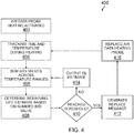
- FIG. 4 An air data probe life expectancy flow diagram 400 of an embodiment is illustrated in Figure 4 .
- the air data probe life expectancy flow diagram 400 is provided as a sequential series of steps. The sequence of steps may be different in other embodiments. Hence, embodiments are not limited by the sequence of steps set out in Figure 4 .
- the air data probe life expectancy flow diagram 400 starts when an associated heating element 104 of an air data probe 102 is activated at step (402). During the heating of air data probe 102, the controller 110, with the use of clock 111 tracks the time and with the current sensor 108 tracks the temperature of the heating element 104.
- the controller 110 sums the di/Di values across temperature ranges as the heating element 104 of the air data probe 102 is being heated.
- the current determined remaining life estimate based on the di/Di is determined at step (408) via the controller 110.
- the remaining life estimate is based off of the then current value of the di/Di in an embodiment.
- the process then continues at step (406) summing di/Di values as long as the heating element is activate. Further in one embodiment, the air data probe 102 is replaced at step (412) when a replace message generated at step (412) is received at the I/O 414. The process continues by monitoring the heating element of the new air data probe 102 at step (404) of the probe 102 when heating is activated.
- airline operators are so averse to suffering an unscheduled repair of air data probes that they are removing the probes based on hours of operation well before their predicted end of life.
- a much more effective tool for predicting end of life based on the operational exposure of the air data probes via time and temperature history is provided.
- embodiments provide a predictable maintenance, fewer grounded aircraft, predictable and lower probe spare inventory and longer use of existing probes that would otherwise have thousands of hours more useful life left when replaced based purely on hours of operation.
Description
- The health and integrity of aircraft air data sensors play a critical role in safely and effectively flying and controlling an aircraft. Pitot Probes are used to measure the airspeed of an aircraft and Pitot Static probes are used to measure both the plane's altitude and air speed. Inaccurate or false readings from these sensors/instruments can lead to inappropriate flight control which can have fatal consequences. Hence operational air data probes are part of the minimum equipment list required for flight.
- Unanticipated probe failures can lead to aircraft on ground, flight delays and cancelations events that can be very expensive to an air carrier. Aggravating the problem of probe failures that result in unscheduled maintenance, is the fact that the availability of air data probes can be limited. If the air carrier does not carry inventory, or if the inventory is centrally located the lead times and replacement times can be significant. Thus air data probe customers value reliability over almost all other air data probe attributes.
- The aversion to unscheduled maintenance is so strong that many operators pre-emptively replace pitot and other air data probes before they shows signs of aging. For example, one major airline replaces their probes very early in the expected life cycle (after every 18,000 hrs.) to avoid unscheduled removals.
-
EP 3018057 A1 (Rosemount Aerospace Inc. ) describes how a heating element of an air data probe may fail over time due to thermo-mechanical stress, and how a sacrificial wire can be utilized to fail prior to the heating element so as to provide an indication that the heating element should be replaced.US 6,336,083 B1 (Watlow Electric Manufacturing Company ) describes a known method for predicting the failure of resistive heating elements using a compiled life factor database which indicates the relative heating element life as a function of a specific operating temperature. The method can either be carried out actively by continuously measuring the operating temperature of the heating element and decrementing a count of the remaining heating life based on the measured operating temperature, or the method may be carried out passively by estimating the operating profile of the heating element due to its intended application and determining the remaining heating life based on estimated average operating temperatures.JP 2012/253222 A (Hitachi Int. Electric Inc. - The above-mentioned problems of current systems are addressed by embodiments of the present invention and will be understood by reading and studying the following specification. The following summary is made by way of example and not by way of limitation. It is merely provided to aid the reader in understanding some of the aspects of the invention. Embodiments provide a method of determining when to replace an air data probe based on an expected life of the air data probe.
- The present invention is defined by the independent claims, to which reference should now be made. Advantageous embodiments are set out in the dependent claims.
- The present invention can be more easily understood and further advantages and uses thereof will be more readily apparent, when considered in view of the detailed description and the following figures in which:
-
Figure 1 illustrates a block diagram of an air data probe operating and monitoring system according to one example embodiment; -
Figure 2 illustrates a temperature monitoring flow diagram for an air data probe according to one example embodiment; -
Figure 3 illustrates a set up flow diagram for updating the prediction algorithm based on collected data according to one example embodiment; and -
Figure 4 illustrates an air data probe life expectancy flow diagram according to one example embodiment. - In accordance with common practice, the various described features are not drawn to scale but are drawn to emphasize specific features relevant to the present invention. Reference characters denote like elements throughout Figures and text.
- In the following detailed description, reference is made to the accompanying drawings, which form a part hereof, and in which is shown by way of illustration specific embodiments in which the inventions may be practiced. These embodiments are described in sufficient detail to enable those skilled in the art to practice the invention, and it is to be understood that other embodiments may be utilized and that changes may be made without departing from the spirit and scope of the present invention. The following detailed description is, therefore, not to be taken in a limiting sense, and the scope of the present invention is defined only by the claims.
- Embodiments of the present invention provide a system and method of predicting when to replace an air data probe. For an airline operator a high reliability outcome can be achieved if failures are predicted with sufficient forewarning to ensure that the probes are replaced during a scheduled maintenance event. Operationally, a high reliability outcome can be achieved if unscheduled maintenance can be avoided. Embodiments provide an air data probe that can accurately track and predict its health state so that remaining utility/lifetime can be determined so the air data probe can be replaced during a scheduled maintenance event.
- The vast majority of air data probe failures are due to heater cable (heater element) failures. These type of failures tend to occur abruptly with little or no advanced notice. Investigations have shown that a simple current monitoring approach is not sufficient to track the onset of degradation and therefore is not a reliable approach to use in predicting the end of life of air data probes.
-
Figure 1 illustrates an air data probe operating and monitoringsystem 100 of one example embodiment. Thesystem 100 includes anair data probe 102. Within the air data probe is aheating element 104. Although only oneheating element 104 is illustrated, anair data probe 102 may have more than one heating element. Hence, embodiments are not limited to oneheating element 104. Theheating element 104 is conductively coupled to apower source 106 viaconductive lines conductive line 107 to measure current flowing through theheating element 104. - A
controller 110 is coupled to control operations of thepower source 106. In particular, thecontroller 110 controls the drive voltage ofpower source 106. The control of the drive voltage applied to theheating element 104 is based at least in part on current operating parameters of the aircraft and conditions theair data probe 102 are experiencing. Thecontroller 106 is further in communication with an output of thecurrent sensor 108. In general, the controller 110 (processor) may include any one or more of a microprocessor, a digital signal processor (DSP), an application specific integrated circuit (ASIC), a field program gate array (FPGA), or equivalent discrete or integrated logic circuitry. In some example embodiments,controller 110 may include multiple components, such as any combination of one or more microprocessors, one or more controllers, one or more DSPs, one or more ASICs, one or more FPGAs, as well as other discrete or integrated logic circuitry. The functions attributed tocontroller 110 herein may be embodied as software, firmware, hardware or any combination thereof.Memory 112, which is also in communication with thecontroller 110, may include computer-readable instructions that, when executed bycontroller 110 provide functions of thecontroller 110. Such functions may include the functions relating to the prediction of when to replace theair data probe 102. The computer readable instructions may be encoded within thememory 112.Memory 112 may comprise computer readable storage media including any volatile, nonvolatile, magnetic, optical, or electrical media, such as, but not limited to, a random access memory (RAM), read-only memory (ROM), non-volatile RAM (NVRAM), electrically-erasable programmable ROM (EEPROM), flash memory, or any other storage medium. - Further in communication with the
controller 110 is an input/output 114. In embodiments, thecontroller 110 outputs information relating to the life expectancy of theair data probe 102 to the input/output 114 and receives information regarding temperature ranges and associated life expectancy values as discussed below in detail. Aclock 111 is used by thecontroller 110 to track time theheating element 104 is activated as discussed below. - Tests conducted have found that the life times of electrical heaters are strongly dependent on the applied current or voltage and consequentially the temperature that the filament reaches during operation. A power law relationships can be used to predict the decrease in lifetime that occur when the applied voltage or current is increased. The heater cable (heater element) lifetimes are also strongly dependent on the operational conditions that they experience. A first order model of the lifetimes for the heater cables follow a power law relationship, as provided below, that is dependent on operational temperature, where the value for n can be found empirically through testing.

- The exact relationship between lifetime, operational temperature and time may be different than the equation provided above. However, from this equation it is realized that both time and temperature are the important life limiting drivers. Since not all aircraft are operated in a similar manner e.g. short versus long haul, their air data probes will not see the same operational conditions. Thus strictly counting flight hours or even cycles is not as effective as finding the cumulative duration that the probe spends at various temperatures.
- The operational temperature can be determined through commonly monitored conditions without the need to further instrument the probe in some embodiments. For example, some air data probes are made with a heating element that use a positive temperature coefficient (PTC) metal i.e. Balco, with a tightly controlled length and resistance value. Because the resistance of the heater cable (heating element) changes with temperature due to the PTC material, a functional relationship or table/mapping can be established between the heater cable resistance and the total cable temperature. The resistance of the cable can be determined from the current drawn for a given drive voltage according to the formula resistance (R) = current (C)/voltage (V). The drive voltages are generally known on board the aircraft and may change when the aircraft is on the ground versus in flight. The current drawn by the probes are also often monitored. For example,
Figure 2 illustrates a temperature monitoring flow diagram 200 for monitoring cable temperature over time for an air data probe of an example embodiment. The temperature flow diagram 200 illustrates that the air data probe is operated at different temperatures during different operations of the aircraft. The data collected may be used for calculating hours of operation and/or number of cycles but more importantly it may be used to determine the cumulative 'thermal fatigue' experienced by the probes based on the individual operational experience as described below. - In this prior art example, the current and on-ground condition is monitored at block (202). If it is determined at block (204) that the aircraft is on the ground a defined on-ground voltage is provided by the power source at step (205). The internal cable resistance is determined from on-ground voltage and monitored current values at block (207). The internal cable temperature is determined from the resistance and block (210). If it is determined that the aircraft is not on ground at block (204), an in-flight voltage is defined at block (206). The internal cable resistance is then determined from in-flight voltage and monitored current values at block (208). The internal cable temperature is determined from the resistance at block (210). Once an internal temperature is determined at block (210), the temperature and time it was determined, (with clock 201) is recorded at block (212).
- Since the
air data probe 102 is not constantly operating at a single temperature there needs to be a way to accumulate the thermal stress experienced by the probe heater over time. In some embodiments, a modified Miner's rule is used to accumulate the thermal stress experienced over time. The Miner's rule is commonly used for calculating the remaining life of a structural component that is undergoing cyclical stress. Embodiments consider thermally induced fatigue experienced by the probe as analogous to cyclical fatigue stress. Use of the Miner's rule also known as the Palmgren-Miner linear damage hypothesis, provides a method for combining different operational exposures along with the time of exposure to determine the cumulative life consumed by the probe while in operation. The rule is as follows:
- Where C is the fraction life consumed. When C= 1 the probe life has been expended. Di is the length of time that the probe can survive under a given temperature condition, i. And di is the accumulated length of time that the probe has experience under that temperature condition.
- In implementing this approach embodiments break the continuous range of temperatures (current drawn) into discrete segments related to current drawn. These segments may be defined with thresholds similar to how an air data heater controller (ADHC) determines if the probe is operational. For example, the data collected could be continuously updating a histogram of temperature versus time. This histogram may be implemented in software or a simple digital hardware design that accumulates counts (time) at given threshold values (temperature conditions). This data may be stored locally on a digital probe or collected, stored or broadcast by an air data module. Further in one example embodiment, the data is passed to an onboard maintenance computer for local storage or datalink transmission to a ground based recipient. The remaining life of the probe may be determined using the above equation with the histogram counts.
- A set up flow diagram 300 for updating the prediction algorithm based on collected data of an embodiment is illustrated in
Figure 3 . The set up flow diagram 300 starts at step (302), setting temperatures ranges. At step (304), a period of time of life expectancy is assigned to each temperature range. In one embodiment the life expectancy value is Di as discussed above. In an embodiment, the period of time of life expectancy for each temperature range is stored inmemory 112 via the I/O 114. Further in embodiments, the period of time of life expectancy (Di values) for each temperature range may be updated as information relating to period of time of life expectancy vs temperature range is gathered. Hence in this embodiment, when it is determined if that updated values are available atblock step 306, update values can be used to improve the prediction of remaining life are provided atstep 308. - An air data probe life expectancy flow diagram 400 of an embodiment is illustrated in
Figure 4 . The air data probe life expectancy flow diagram 400 is provided as a sequential series of steps. The sequence of steps may be different in other embodiments. Hence, embodiments are not limited by the sequence of steps set out inFigure 4 . - The air data probe life expectancy flow diagram 400 starts when an associated
heating element 104 of anair data probe 102 is activated at step (402). During the heating ofair data probe 102, thecontroller 110, with the use ofclock 111 tracks the time and with thecurrent sensor 108 tracks the temperature of theheating element 104. - At step (406), the
controller 110, sums the di/Di values across temperature ranges as theheating element 104 of theair data probe 102 is being heated. The current determined remaining life estimate based on the di/Di is determined at step (408) via thecontroller 110. In an embodiment, it is then determined at step (410) if a defined threshold is reached by comparing a current result of C, the sum of di/Di components, to the defined threshold. If the threshold is reached at step (410), a replace message is generated at step (412) that is communicated to the I/O 114. If the threshold is not reached at step (410), in one embodiment, an estimate of remaining life estimate is output to the I/O 114 at step (414). The remaining life estimate is based off of the then current value of the di/Di in an embodiment. The process then continues at step (406) summing di/Di values as long as the heating element is activate. Further in one embodiment, theair data probe 102 is replaced at step (412) when a replace message generated at step (412) is received at the I/O 414. The process continues by monitoring the heating element of the newair data probe 102 at step (404) of theprobe 102 when heating is activated. - In summary, airline operators are so averse to suffering an unscheduled repair of air data probes that they are removing the probes based on hours of operation well before their predicted end of life. With the implementation of the above described embodiments, a much more effective tool for predicting end of life based on the operational exposure of the air data probes via time and temperature history is provided. Moreover, embodiments provide a predictable maintenance, fewer grounded aircraft, predictable and lower probe spare inventory and longer use of existing probes that would otherwise have thousands of hours more useful life left when replaced based purely on hours of operation.
Claims (9)
- A method of determining when to replace an air data probe (102), the method comprising:measuring a temperature of a heating element (104) of the air data probe (102);tracking an amount of time the heating element (104) has a measured temperature within temperature ranges;applying a cumulated weighted function that predicts the life expectancy of the air data probe (102) based on an accumulated time the heating element (104) is tracked within each temperature range; andoutputting an air data probe replacement indication when a result of the cumulated weighted function reaches a replacement threshold.
- The method of claim 1, wherein measuring the temperature of the heating element (104) further comprises:determining an operational resistance of the heating element (104) by measuring the current drawn by the heating element (104) for a given drive voltage; andderiving the temperature based on the determined resistance.
- The method of claim 1, further comprising:
adjusting the replacement threshold based at least in part on gathered data relating to the remaining life of the air data probe. - The method of claim 1, further comprising;
generating a remaining life estimate based at least in part on the measured temperature of the heating element and the tracked amount of time the heating element is within at least one temperature range. - The method of claim 1, further comprising:setting temperature ranges; andassociating a period of time of life expectancy with each temperature range.
- An air data probe operating and monitoring system (100), the system comprising:at least one heating element (104) configured to be housed within the air data probe (102);a power source (106) coupled to the at least one heating element (104);at least one current sensor (108) coupled to sense a current draw through the at least one heating element (104);at least one clock (111);at least one memory (112) to store at least operating instructions and sensor data from the at least one current sensor (108);at least one controller (110) coupled to control the power source (106) to provide select drive voltages for the at least one heating element (104) based on a current operating condition of the air data probe (102),the at least one controller (110) being in communication with the at least one current sensor (108),the at least one controller (110) being further configured to implement the operating instructions in the at least one memory (112) to track time that the at least one heating element (104) of the air data probe (102) has a temperature within defined temperature ranges using the at least one clock (111),the at least one controller (110) being configured to determine the temperature of the at least one heating element (104),the at least one controller (110) being further configured to apply a cumulated weighted function that predicts the life expectancy of the air data probe (102) based on an accumulated time the heating element (104) is tracked within each temperature range; andan output in communication with the at least one controller (110), the at least one controller (110) configured to communicate a replace air data probe message to the output when a result of the cumulated weighted function reaches a select threshold.
- The system of claim 6, wherein the at least one controller (110) is further configured to determine the temperature of the at least one heating element (104) by measuring a current drawn by the at least one heating element (104) for a given drive voltage with the current sensor (108).
- The system of claim 6, wherein the at least one controller (110) is further configured to sum a period of time of life expectancies over a length of time the at least one heating element (104) can survive under a given temperature range across all temperature ranges in applying the cumulated weighted function.
- The system of claim 6, wherein the at least one controller (110) is further configured to generate a remaining life expectancy signal that is communicated to the output.
Applications Claiming Priority (1)
| Application Number | Priority Date | Filing Date | Title |
|---|---|---|---|
| US16/118,905 US11016117B2 (en) | 2018-08-31 | 2018-08-31 | Air data probe replacement determination system |
Publications (2)
| Publication Number | Publication Date |
|---|---|
| EP3617713A1 EP3617713A1 (en) | 2020-03-04 |
| EP3617713B1 true EP3617713B1 (en) | 2021-12-29 |
Family
ID=67809401
Family Applications (1)
| Application Number | Title | Priority Date | Filing Date |
|---|---|---|---|
| EP19194494.1A Active EP3617713B1 (en) | 2018-08-31 | 2019-08-29 | Air data probe replacement determination system |
Country Status (3)
| Country | Link |
|---|---|
| US (1) | US11016117B2 (en) |
| EP (1) | EP3617713B1 (en) |
| CN (1) | CN110873830A (en) |
Families Citing this family (7)
| Publication number | Priority date | Publication date | Assignee | Title |
|---|---|---|---|---|
| US11237067B2 (en) * | 2019-08-20 | 2022-02-01 | Kidde Technologies, Inc. | Uncertainty diagnosis for temperature detection systems |
| US11422153B2 (en) | 2020-01-24 | 2022-08-23 | Honeywell International Inc. | Air data probe replacement determination system |
| US11914003B2 (en) | 2021-03-30 | 2024-02-27 | Rosemount Aerospace Inc. | Predicting failure and/or estimating remaining useful life of an air-data-probe heater |
| US11762040B2 (en) * | 2021-03-30 | 2023-09-19 | Rosemount Aerospace Inc. | Predicting failure and/or estimating remaining useful life of an air-data-probe heater |
| US11913977B2 (en) | 2021-05-17 | 2024-02-27 | Rosemount Aerospace Inc. | Positive temperature coefficient resistor heater assembly health monitoring |
| CN113408221B (en) * | 2021-07-06 | 2022-04-15 | 太仓比泰科自动化设备有限公司 | Probe service life prediction method, system, device and storage medium |
| US11867746B2 (en) | 2021-09-14 | 2024-01-09 | Hamilton Sundstrand Corporation | Failure detection system for integrated circuit components |
Family Cites Families (18)
| Publication number | Priority date | Publication date | Assignee | Title |
|---|---|---|---|---|
| US6288561B1 (en) * | 1988-05-16 | 2001-09-11 | Elm Technology Corporation | Method and apparatus for probing, testing, burn-in, repairing and programming of integrated circuits in a closed environment using a single apparatus |
| US5464965A (en) | 1993-04-20 | 1995-11-07 | Honeywell Inc. | Apparatus for controlling temperature of an element having a temperature variable resistance |
| US6336083B1 (en) | 1999-05-21 | 2002-01-01 | Watlow Electric Manufacturing Company | Method and apparatus for predicting heater failure |
| US6414282B1 (en) | 2000-11-01 | 2002-07-02 | Rosemount Aerospace Inc. | Active heater control circuit and method used for aerospace probes |
| JP2004093451A (en) * | 2002-09-02 | 2004-03-25 | Tokyo Electron Ltd | Probe method and probe device |
| CN100367015C (en) * | 2003-07-17 | 2008-02-06 | 上海锅炉厂有限公司 | Thermocouple temperature monitoring method and system for air preheater |
| US7725293B2 (en) | 2006-12-07 | 2010-05-25 | General Electric Company | System and method for equipment remaining life estimation |
| ITMI20071048A1 (en) | 2007-05-23 | 2008-11-24 | Nuovo Pignone Spa | METHOD FOR THE CONTROL OF THE PRESSURE DYNAMICS AND FOR THE ESTIMATE OF THE LIFE CYCLE OF THE COMBUSTION CHAMBER OF A GAS TURBINE |
| US8279072B2 (en) * | 2008-03-17 | 2012-10-02 | Mrl Industries Inc. | System to monitor a consumable part and method to monitor performance life and predict maintenance thereof |
| FR2970358B1 (en) | 2011-01-06 | 2019-04-12 | Airbus Helicopters | PROGNOSTIC OF DURATION BEFORE MAINTENANCE BY FUSION BETWEEN MODELING AND SIMULATION, FOR ELECTRONIC EQUIPMENTS ON BOARD IN AN AIRCRAFT |
| JP2012253222A (en) | 2011-06-03 | 2012-12-20 | Hitachi Kokusai Electric Inc | Method of predicting service life of resistance heating type heater, and thermal processing device |
| US9617010B2 (en) | 2014-03-28 | 2017-04-11 | Bell Helicopter Textron Inc. | Aircraft prognostics health system |
| US9927480B2 (en) * | 2014-11-06 | 2018-03-27 | Rosemount Aerospace, Inc. | System and method for probe heater health indication |
| US10227139B2 (en) * | 2015-03-23 | 2019-03-12 | Rosemount Aerospace Inc. | Heated air data probes |
| US10102531B2 (en) | 2016-01-13 | 2018-10-16 | Donald Remboski | Real time failure analysis and accurate warranty claim assesment |
| US9523594B1 (en) | 2016-02-23 | 2016-12-20 | Honeywell International Inc. | Power control for an air data probe |
| US10180449B2 (en) | 2017-03-24 | 2019-01-15 | Rosemount Aerospace Inc. | Probe heater remaining useful life determination |
| US10689004B1 (en) | 2017-04-28 | 2020-06-23 | Ge Global Sourcing Llc | Monitoring system for detecting degradation of a propulsion subsystem |
-
2018
- 2018-08-31 US US16/118,905 patent/US11016117B2/en active Active
-
2019
- 2019-08-15 CN CN201910754748.3A patent/CN110873830A/en active Pending
- 2019-08-29 EP EP19194494.1A patent/EP3617713B1/en active Active
Also Published As
| Publication number | Publication date |
|---|---|
| CN110873830A (en) | 2020-03-10 |
| EP3617713A1 (en) | 2020-03-04 |
| US11016117B2 (en) | 2021-05-25 |
| US20200072866A1 (en) | 2020-03-05 |
Similar Documents
| Publication | Publication Date | Title |
|---|---|---|
| EP3617713B1 (en) | Air data probe replacement determination system | |
| JP7266587B2 (en) | Method and system for controlling rechargeable batteries | |
| US9494932B2 (en) | Monitoring device, monitoring method, and recording medium | |
| CN106919141B (en) | Preventive maintenance management system, unit control device, and preventive maintenance management method | |
| US5668529A (en) | Method of statistically determining brake lining wear using temperature sensing | |
| EP3709039B1 (en) | Battery life learning device, battery life prediction device, method and program | |
| JPH09223833A (en) | Laser system that can forecast useful life of compomemt and method of forecasting | |
| US11338940B2 (en) | Predictive part maintenance | |
| CN110888412B (en) | Semiconductor device and analysis system | |
| EP3745227A1 (en) | Systems and methods for predicting the health of integrated drive generators | |
| EP3855189B1 (en) | Air data probe replacement determination system | |
| EP2295997B1 (en) | Method for diagnosing batteries | |
| JP2011511205A (en) | Method and apparatus for monitoring at least one glow plug of an internal combustion engine | |
| KR102238293B1 (en) | Method for detecting damage during operation of a gas turbine | |
| DE102019111555A1 (en) | Method and apparatus for detecting thermal runaway of a lithium ion battery | |
| US20130114207A1 (en) | Electronic assembly with cooling device | |
| CN114036632A (en) | Method for evaluating the service life of an onboard device of an aircraft | |
| US11930563B2 (en) | Monitoring and extending heater life through power supply polarity switching | |
| EP3893072B1 (en) | Prognostic and health monitoring by energy metering at power supply interface | |
| US20080208535A1 (en) | Disc array device | |
| EP4311067A1 (en) | Method and system for facilitating adapated maintenance of emergency lighting systems | |
| EP4071573A2 (en) | A method for predicting a remaining lifetime parameter of a component | |
| DE102022102765A1 (en) | Method and device for determining the state of the thermal connection of an electrical component | |
| EP3561521A1 (en) | Real time in field monitoring of air data pitot tube heating arrangement | |
| CN117941241A (en) | Method and monitoring device for monitoring the state of a machine |
Legal Events
| Date | Code | Title | Description |
|---|---|---|---|
| PUAI | Public reference made under article 153(3) epc to a published international application that has entered the european phase |
Free format text: ORIGINAL CODE: 0009012 |
|
| STAA | Information on the status of an ep patent application or granted ep patent |
Free format text: STATUS: THE APPLICATION HAS BEEN PUBLISHED |
|
| AK | Designated contracting states |
Kind code of ref document: A1 Designated state(s): AL AT BE BG CH CY CZ DE DK EE ES FI FR GB GR HR HU IE IS IT LI LT LU LV MC MK MT NL NO PL PT RO RS SE SI SK SM TR |
|
| AX | Request for extension of the european patent |
Extension state: BA ME |
|
| STAA | Information on the status of an ep patent application or granted ep patent |
Free format text: STATUS: REQUEST FOR EXAMINATION WAS MADE |
|
| 17P | Request for examination filed |
Effective date: 20200414 |
|
| RBV | Designated contracting states (corrected) |
Designated state(s): AL AT BE BG CH CY CZ DE DK EE ES FI FR GB GR HR HU IE IS IT LI LT LU LV MC MK MT NL NO PL PT RO RS SE SI SK SM TR |
|
| STAA | Information on the status of an ep patent application or granted ep patent |
Free format text: STATUS: EXAMINATION IS IN PROGRESS |
|
| 17Q | First examination report despatched |
Effective date: 20210223 |
|
| GRAP | Despatch of communication of intention to grant a patent |
Free format text: ORIGINAL CODE: EPIDOSNIGR1 |
|
| STAA | Information on the status of an ep patent application or granted ep patent |
Free format text: STATUS: GRANT OF PATENT IS INTENDED |
|
| INTG | Intention to grant announced |
Effective date: 20210813 |
|
| GRAS | Grant fee paid |
Free format text: ORIGINAL CODE: EPIDOSNIGR3 |
|
| GRAA | (expected) grant |
Free format text: ORIGINAL CODE: 0009210 |
|
| STAA | Information on the status of an ep patent application or granted ep patent |
Free format text: STATUS: THE PATENT HAS BEEN GRANTED |
|
| AK | Designated contracting states |
Kind code of ref document: B1 Designated state(s): AL AT BE BG CH CY CZ DE DK EE ES FI FR GB GR HR HU IE IS IT LI LT LU LV MC MK MT NL NO PL PT RO RS SE SI SK SM TR |
|
| REG | Reference to a national code |
Ref country code: GB Ref legal event code: FG4D |
|
| REG | Reference to a national code |
Ref country code: CH Ref legal event code: EP |
|
| REG | Reference to a national code |
Ref country code: AT Ref legal event code: REF Ref document number: 1459067 Country of ref document: AT Kind code of ref document: T Effective date: 20220115 |
|
| REG | Reference to a national code |
Ref country code: IE Ref legal event code: FG4D |
|
| REG | Reference to a national code |
Ref country code: DE Ref legal event code: R096 Ref document number: 602019010404 Country of ref document: DE |
|
| REG | Reference to a national code |
Ref country code: LT Ref legal event code: MG9D |
|
| PG25 | Lapsed in a contracting state [announced via postgrant information from national office to epo] |
Ref country code: RS Free format text: LAPSE BECAUSE OF FAILURE TO SUBMIT A TRANSLATION OF THE DESCRIPTION OR TO PAY THE FEE WITHIN THE PRESCRIBED TIME-LIMIT Effective date: 20211229 Ref country code: LT Free format text: LAPSE BECAUSE OF FAILURE TO SUBMIT A TRANSLATION OF THE DESCRIPTION OR TO PAY THE FEE WITHIN THE PRESCRIBED TIME-LIMIT Effective date: 20211229 Ref country code: FI Free format text: LAPSE BECAUSE OF FAILURE TO SUBMIT A TRANSLATION OF THE DESCRIPTION OR TO PAY THE FEE WITHIN THE PRESCRIBED TIME-LIMIT Effective date: 20211229 Ref country code: BG Free format text: LAPSE BECAUSE OF FAILURE TO SUBMIT A TRANSLATION OF THE DESCRIPTION OR TO PAY THE FEE WITHIN THE PRESCRIBED TIME-LIMIT Effective date: 20220329 |
|
| REG | Reference to a national code |
Ref country code: NL Ref legal event code: MP Effective date: 20211229 |
|
| REG | Reference to a national code |
Ref country code: AT Ref legal event code: MK05 Ref document number: 1459067 Country of ref document: AT Kind code of ref document: T Effective date: 20211229 |
|
| PG25 | Lapsed in a contracting state [announced via postgrant information from national office to epo] |
Ref country code: SE Free format text: LAPSE BECAUSE OF FAILURE TO SUBMIT A TRANSLATION OF THE DESCRIPTION OR TO PAY THE FEE WITHIN THE PRESCRIBED TIME-LIMIT Effective date: 20211229 Ref country code: NO Free format text: LAPSE BECAUSE OF FAILURE TO SUBMIT A TRANSLATION OF THE DESCRIPTION OR TO PAY THE FEE WITHIN THE PRESCRIBED TIME-LIMIT Effective date: 20220329 Ref country code: LV Free format text: LAPSE BECAUSE OF FAILURE TO SUBMIT A TRANSLATION OF THE DESCRIPTION OR TO PAY THE FEE WITHIN THE PRESCRIBED TIME-LIMIT Effective date: 20211229 Ref country code: HR Free format text: LAPSE BECAUSE OF FAILURE TO SUBMIT A TRANSLATION OF THE DESCRIPTION OR TO PAY THE FEE WITHIN THE PRESCRIBED TIME-LIMIT Effective date: 20211229 Ref country code: GR Free format text: LAPSE BECAUSE OF FAILURE TO SUBMIT A TRANSLATION OF THE DESCRIPTION OR TO PAY THE FEE WITHIN THE PRESCRIBED TIME-LIMIT Effective date: 20220330 |
|
| PG25 | Lapsed in a contracting state [announced via postgrant information from national office to epo] |
Ref country code: NL Free format text: LAPSE BECAUSE OF FAILURE TO SUBMIT A TRANSLATION OF THE DESCRIPTION OR TO PAY THE FEE WITHIN THE PRESCRIBED TIME-LIMIT Effective date: 20211229 |
|
| PG25 | Lapsed in a contracting state [announced via postgrant information from national office to epo] |
Ref country code: SM Free format text: LAPSE BECAUSE OF FAILURE TO SUBMIT A TRANSLATION OF THE DESCRIPTION OR TO PAY THE FEE WITHIN THE PRESCRIBED TIME-LIMIT Effective date: 20211229 Ref country code: SK Free format text: LAPSE BECAUSE OF FAILURE TO SUBMIT A TRANSLATION OF THE DESCRIPTION OR TO PAY THE FEE WITHIN THE PRESCRIBED TIME-LIMIT Effective date: 20211229 Ref country code: RO Free format text: LAPSE BECAUSE OF FAILURE TO SUBMIT A TRANSLATION OF THE DESCRIPTION OR TO PAY THE FEE WITHIN THE PRESCRIBED TIME-LIMIT Effective date: 20211229 Ref country code: PT Free format text: LAPSE BECAUSE OF FAILURE TO SUBMIT A TRANSLATION OF THE DESCRIPTION OR TO PAY THE FEE WITHIN THE PRESCRIBED TIME-LIMIT Effective date: 20220429 Ref country code: ES Free format text: LAPSE BECAUSE OF FAILURE TO SUBMIT A TRANSLATION OF THE DESCRIPTION OR TO PAY THE FEE WITHIN THE PRESCRIBED TIME-LIMIT Effective date: 20211229 Ref country code: EE Free format text: LAPSE BECAUSE OF FAILURE TO SUBMIT A TRANSLATION OF THE DESCRIPTION OR TO PAY THE FEE WITHIN THE PRESCRIBED TIME-LIMIT Effective date: 20211229 Ref country code: CZ Free format text: LAPSE BECAUSE OF FAILURE TO SUBMIT A TRANSLATION OF THE DESCRIPTION OR TO PAY THE FEE WITHIN THE PRESCRIBED TIME-LIMIT Effective date: 20211229 |
|
| PG25 | Lapsed in a contracting state [announced via postgrant information from national office to epo] |
Ref country code: PL Free format text: LAPSE BECAUSE OF FAILURE TO SUBMIT A TRANSLATION OF THE DESCRIPTION OR TO PAY THE FEE WITHIN THE PRESCRIBED TIME-LIMIT Effective date: 20211229 Ref country code: AT Free format text: LAPSE BECAUSE OF FAILURE TO SUBMIT A TRANSLATION OF THE DESCRIPTION OR TO PAY THE FEE WITHIN THE PRESCRIBED TIME-LIMIT Effective date: 20211229 |
|
| PG25 | Lapsed in a contracting state [announced via postgrant information from national office to epo] |
Ref country code: IS Free format text: LAPSE BECAUSE OF FAILURE TO SUBMIT A TRANSLATION OF THE DESCRIPTION OR TO PAY THE FEE WITHIN THE PRESCRIBED TIME-LIMIT Effective date: 20220429 |
|
| REG | Reference to a national code |
Ref country code: DE Ref legal event code: R097 Ref document number: 602019010404 Country of ref document: DE |
|
| PG25 | Lapsed in a contracting state [announced via postgrant information from national office to epo] |
Ref country code: DK Free format text: LAPSE BECAUSE OF FAILURE TO SUBMIT A TRANSLATION OF THE DESCRIPTION OR TO PAY THE FEE WITHIN THE PRESCRIBED TIME-LIMIT Effective date: 20211229 Ref country code: AL Free format text: LAPSE BECAUSE OF FAILURE TO SUBMIT A TRANSLATION OF THE DESCRIPTION OR TO PAY THE FEE WITHIN THE PRESCRIBED TIME-LIMIT Effective date: 20211229 |
|
| PLBE | No opposition filed within time limit |
Free format text: ORIGINAL CODE: 0009261 |
|
| STAA | Information on the status of an ep patent application or granted ep patent |
Free format text: STATUS: NO OPPOSITION FILED WITHIN TIME LIMIT |
|
| 26N | No opposition filed |
Effective date: 20220930 |
|
| PG25 | Lapsed in a contracting state [announced via postgrant information from national office to epo] |
Ref country code: SI Free format text: LAPSE BECAUSE OF FAILURE TO SUBMIT A TRANSLATION OF THE DESCRIPTION OR TO PAY THE FEE WITHIN THE PRESCRIBED TIME-LIMIT Effective date: 20211229 |
|
| REG | Reference to a national code |
Ref country code: DE Ref legal event code: R119 Ref document number: 602019010404 Country of ref document: DE |
|
| PG25 | Lapsed in a contracting state [announced via postgrant information from national office to epo] |
Ref country code: MC Free format text: LAPSE BECAUSE OF FAILURE TO SUBMIT A TRANSLATION OF THE DESCRIPTION OR TO PAY THE FEE WITHIN THE PRESCRIBED TIME-LIMIT Effective date: 20211229 |
|
| REG | Reference to a national code |
Ref country code: CH Ref legal event code: PL |
|
| PG25 | Lapsed in a contracting state [announced via postgrant information from national office to epo] |
Ref country code: LU Free format text: LAPSE BECAUSE OF NON-PAYMENT OF DUE FEES Effective date: 20220829 Ref country code: LI Free format text: LAPSE BECAUSE OF NON-PAYMENT OF DUE FEES Effective date: 20220831 Ref country code: CH Free format text: LAPSE BECAUSE OF NON-PAYMENT OF DUE FEES Effective date: 20220831 |
|
| REG | Reference to a national code |
Ref country code: BE Ref legal event code: MM Effective date: 20220831 |
|
| PG25 | Lapsed in a contracting state [announced via postgrant information from national office to epo] |
Ref country code: IT Free format text: LAPSE BECAUSE OF FAILURE TO SUBMIT A TRANSLATION OF THE DESCRIPTION OR TO PAY THE FEE WITHIN THE PRESCRIBED TIME-LIMIT Effective date: 20211229 |
|
| P01 | Opt-out of the competence of the unified patent court (upc) registered |
Effective date: 20230525 |
|
| PG25 | Lapsed in a contracting state [announced via postgrant information from national office to epo] |
Ref country code: IE Free format text: LAPSE BECAUSE OF NON-PAYMENT OF DUE FEES Effective date: 20220829 Ref country code: DE Free format text: LAPSE BECAUSE OF NON-PAYMENT OF DUE FEES Effective date: 20230301 |
|
| PG25 | Lapsed in a contracting state [announced via postgrant information from national office to epo] |
Ref country code: BE Free format text: LAPSE BECAUSE OF NON-PAYMENT OF DUE FEES Effective date: 20220831 |
|
| PGFP | Annual fee paid to national office [announced via postgrant information from national office to epo] |
Ref country code: FR Payment date: 20230824 Year of fee payment: 5 |
|
| PG25 | Lapsed in a contracting state [announced via postgrant information from national office to epo] |
Ref country code: HU Free format text: LAPSE BECAUSE OF FAILURE TO SUBMIT A TRANSLATION OF THE DESCRIPTION OR TO PAY THE FEE WITHIN THE PRESCRIBED TIME-LIMIT; INVALID AB INITIO Effective date: 20190829 |
|
| GBPC | Gb: european patent ceased through non-payment of renewal fee |
Effective date: 20230829 |
|
| PG25 | Lapsed in a contracting state [announced via postgrant information from national office to epo] |
Ref country code: CY Free format text: LAPSE BECAUSE OF FAILURE TO SUBMIT A TRANSLATION OF THE DESCRIPTION OR TO PAY THE FEE WITHIN THE PRESCRIBED TIME-LIMIT Effective date: 20211229 |