EP3587763A1 - Method for regulating a fluid energy machine and a control assembly, in particular for carrying out the method - Google Patents
Method for regulating a fluid energy machine and a control assembly, in particular for carrying out the method Download PDFInfo
- Publication number
- EP3587763A1 EP3587763A1 EP19183207.0A EP19183207A EP3587763A1 EP 3587763 A1 EP3587763 A1 EP 3587763A1 EP 19183207 A EP19183207 A EP 19183207A EP 3587763 A1 EP3587763 A1 EP 3587763A1
- Authority
- EP
- European Patent Office
- Prior art keywords
- speed
- torque
- control
- generator
- sub
- Prior art date
- Legal status (The legal status is an assumption and is not a legal conclusion. Google has not performed a legal analysis and makes no representation as to the accuracy of the status listed.)
- Granted
Links
- 239000012530 fluid Substances 0.000 title claims abstract description 62
- 238000000034 method Methods 0.000 title claims abstract description 46
- 230000001105 regulatory effect Effects 0.000 title claims abstract description 32
- 238000002485 combustion reaction Methods 0.000 claims description 29
- 230000001360 synchronised effect Effects 0.000 claims description 23
- 239000000446 fuel Substances 0.000 claims description 7
- 238000000819 phase cycle Methods 0.000 description 8
- 239000007789 gas Substances 0.000 description 7
- 230000001276 controlling effect Effects 0.000 description 6
- 230000008901 benefit Effects 0.000 description 5
- 238000010586 diagram Methods 0.000 description 5
- 230000008569 process Effects 0.000 description 3
- ATUOYWHBWRKTHZ-UHFFFAOYSA-N Propane Chemical compound CCC ATUOYWHBWRKTHZ-UHFFFAOYSA-N 0.000 description 2
- 230000000694 effects Effects 0.000 description 2
- VNWKTOKETHGBQD-UHFFFAOYSA-N methane Chemical compound C VNWKTOKETHGBQD-UHFFFAOYSA-N 0.000 description 2
- 239000000126 substance Substances 0.000 description 2
- 239000002028 Biomass Substances 0.000 description 1
- 230000004913 activation Effects 0.000 description 1
- 238000013459 approach Methods 0.000 description 1
- -1 biogas Substances 0.000 description 1
- 239000010796 biological waste Substances 0.000 description 1
- 230000008859 change Effects 0.000 description 1
- 238000001816 cooling Methods 0.000 description 1
- 230000008878 coupling Effects 0.000 description 1
- 238000010168 coupling process Methods 0.000 description 1
- 238000005859 coupling reaction Methods 0.000 description 1
- 230000005611 electricity Effects 0.000 description 1
- 238000000855 fermentation Methods 0.000 description 1
- 230000004151 fermentation Effects 0.000 description 1
- 239000003345 natural gas Substances 0.000 description 1
- 239000001294 propane Substances 0.000 description 1
- 239000002994 raw material Substances 0.000 description 1
- 239000007858 starting material Substances 0.000 description 1
- 239000002023 wood Substances 0.000 description 1
Images

Classifications
-
- F—MECHANICAL ENGINEERING; LIGHTING; HEATING; WEAPONS; BLASTING
- F02—COMBUSTION ENGINES; HOT-GAS OR COMBUSTION-PRODUCT ENGINE PLANTS
- F02B—INTERNAL-COMBUSTION PISTON ENGINES; COMBUSTION ENGINES IN GENERAL
- F02B63/00—Adaptations of engines for driving pumps, hand-held tools or electric generators; Portable combinations of engines with engine-driven devices
- F02B63/04—Adaptations of engines for driving pumps, hand-held tools or electric generators; Portable combinations of engines with engine-driven devices for electric generators
-
- F—MECHANICAL ENGINEERING; LIGHTING; HEATING; WEAPONS; BLASTING
- F02—COMBUSTION ENGINES; HOT-GAS OR COMBUSTION-PRODUCT ENGINE PLANTS
- F02D—CONTROLLING COMBUSTION ENGINES
- F02D29/00—Controlling engines, such controlling being peculiar to the devices driven thereby, the devices being other than parts or accessories essential to engine operation, e.g. controlling of engines by signals external thereto
- F02D29/06—Controlling engines, such controlling being peculiar to the devices driven thereby, the devices being other than parts or accessories essential to engine operation, e.g. controlling of engines by signals external thereto peculiar to engines driving electric generators
-
- F—MECHANICAL ENGINEERING; LIGHTING; HEATING; WEAPONS; BLASTING
- F02—COMBUSTION ENGINES; HOT-GAS OR COMBUSTION-PRODUCT ENGINE PLANTS
- F02D—CONTROLLING COMBUSTION ENGINES
- F02D41/00—Electrical control of supply of combustible mixture or its constituents
- F02D41/0025—Controlling engines characterised by use of non-liquid fuels, pluralities of fuels, or non-fuel substances added to the combustible mixtures
- F02D41/0027—Controlling engines characterised by use of non-liquid fuels, pluralities of fuels, or non-fuel substances added to the combustible mixtures the fuel being gaseous
-
- F—MECHANICAL ENGINEERING; LIGHTING; HEATING; WEAPONS; BLASTING
- F02—COMBUSTION ENGINES; HOT-GAS OR COMBUSTION-PRODUCT ENGINE PLANTS
- F02M—SUPPLYING COMBUSTION ENGINES IN GENERAL WITH COMBUSTIBLE MIXTURES OR CONSTITUENTS THEREOF
- F02M21/00—Apparatus for supplying engines with non-liquid fuels, e.g. gaseous fuels stored in liquid form
- F02M21/02—Apparatus for supplying engines with non-liquid fuels, e.g. gaseous fuels stored in liquid form for gaseous fuels
-
- H—ELECTRICITY
- H02—GENERATION; CONVERSION OR DISTRIBUTION OF ELECTRIC POWER
- H02J—CIRCUIT ARRANGEMENTS OR SYSTEMS FOR SUPPLYING OR DISTRIBUTING ELECTRIC POWER; SYSTEMS FOR STORING ELECTRIC ENERGY
- H02J3/00—Circuit arrangements for ac mains or ac distribution networks
- H02J3/38—Arrangements for parallely feeding a single network by two or more generators, converters or transformers
- H02J3/40—Synchronising a generator for connection to a network or to another generator
-
- H—ELECTRICITY
- H02—GENERATION; CONVERSION OR DISTRIBUTION OF ELECTRIC POWER
- H02P—CONTROL OR REGULATION OF ELECTRIC MOTORS, ELECTRIC GENERATORS OR DYNAMO-ELECTRIC CONVERTERS; CONTROLLING TRANSFORMERS, REACTORS OR CHOKE COILS
- H02P23/00—Arrangements or methods for the control of AC motors characterised by a control method other than vector control
- H02P23/0077—Characterised by the use of a particular software algorithm
-
- H—ELECTRICITY
- H02—GENERATION; CONVERSION OR DISTRIBUTION OF ELECTRIC POWER
- H02P—CONTROL OR REGULATION OF ELECTRIC MOTORS, ELECTRIC GENERATORS OR DYNAMO-ELECTRIC CONVERTERS; CONTROLLING TRANSFORMERS, REACTORS OR CHOKE COILS
- H02P9/00—Arrangements for controlling electric generators for the purpose of obtaining a desired output
- H02P9/04—Control effected upon non-electric prime mover and dependent upon electric output value of the generator
-
- F—MECHANICAL ENGINEERING; LIGHTING; HEATING; WEAPONS; BLASTING
- F02—COMBUSTION ENGINES; HOT-GAS OR COMBUSTION-PRODUCT ENGINE PLANTS
- F02B—INTERNAL-COMBUSTION PISTON ENGINES; COMBUSTION ENGINES IN GENERAL
- F02B43/00—Engines characterised by operating on gaseous fuels; Plants including such engines
-
- F—MECHANICAL ENGINEERING; LIGHTING; HEATING; WEAPONS; BLASTING
- F02—COMBUSTION ENGINES; HOT-GAS OR COMBUSTION-PRODUCT ENGINE PLANTS
- F02D—CONTROLLING COMBUSTION ENGINES
- F02D2250/00—Engine control related to specific problems or objectives
- F02D2250/18—Control of the engine output torque
-
- F—MECHANICAL ENGINEERING; LIGHTING; HEATING; WEAPONS; BLASTING
- F02—COMBUSTION ENGINES; HOT-GAS OR COMBUSTION-PRODUCT ENGINE PLANTS
- F02D—CONTROLLING COMBUSTION ENGINES
- F02D2250/00—Engine control related to specific problems or objectives
- F02D2250/18—Control of the engine output torque
- F02D2250/24—Control of the engine output torque by using an external load, e.g. a generator
-
- H—ELECTRICITY
- H02—GENERATION; CONVERSION OR DISTRIBUTION OF ELECTRIC POWER
- H02P—CONTROL OR REGULATION OF ELECTRIC MOTORS, ELECTRIC GENERATORS OR DYNAMO-ELECTRIC CONVERTERS; CONTROLLING TRANSFORMERS, REACTORS OR CHOKE COILS
- H02P23/00—Arrangements or methods for the control of AC motors characterised by a control method other than vector control
- H02P23/14—Estimation or adaptation of motor parameters, e.g. rotor time constant, flux, speed, current or voltage
-
- Y—GENERAL TAGGING OF NEW TECHNOLOGICAL DEVELOPMENTS; GENERAL TAGGING OF CROSS-SECTIONAL TECHNOLOGIES SPANNING OVER SEVERAL SECTIONS OF THE IPC; TECHNICAL SUBJECTS COVERED BY FORMER USPC CROSS-REFERENCE ART COLLECTIONS [XRACs] AND DIGESTS
- Y02—TECHNOLOGIES OR APPLICATIONS FOR MITIGATION OR ADAPTATION AGAINST CLIMATE CHANGE
- Y02T—CLIMATE CHANGE MITIGATION TECHNOLOGIES RELATED TO TRANSPORTATION
- Y02T10/00—Road transport of goods or passengers
- Y02T10/10—Internal combustion engine [ICE] based vehicles
- Y02T10/30—Use of alternative fuels, e.g. biofuels
Definitions
- the invention relates to a method for regulating a fluid energy machine and a regulating arrangement which is used in particular to carry out the method.
- the fluid energy machine is preferably used for a power unit for feeding energy obtained in particular from gaseous fuels such as biogas into an electrical power supply network.
- An electrical power supply network in the sense of the present invention is a power network that serves to supply consumers with electrical energy in electrical power engineering.
- a power network is a network of electrical power lines, in particular overhead lines and underground cables, which in particular connect facilities such as power plants and other energy converters, for example wind energy and photovoltaic systems, switchgear and transformer stations connected to them and the consumers.
- the electrical power supply network can be designed as a so-called interconnected network, which is generally composed of large, spatially adjacent and electrically connected power networks, which comprise a large number of power plants and consumers.
- the electrical power supply network can also be configured as a so-called island network, that is to say as a locally delimited power network that supplies a spatially narrow area and has no direct electrical connection to other power networks.
- Electricity generators for feeding energy into an electrical power supply network are known, in which the energy is obtained from gaseous fuels.
- gaseous fuels For example, biogas, a combustible gas that is produced by fermentation of biomass, is suitable as a gaseous fuel.
- Biogas is usually produced in biogas plants, which are used to ferment biological waste and renewable raw materials.
- Such a power unit usually comprises a generator, which is designed in particular as a synchronous generator, and a fluid energy machine, which is generally designed as an internal combustion engine, and which drives the generator.
- the internal combustion engine converts the chemical energy of the fuel, for example a gas such as biogas, wood gas, mine gas, natural gas or propane, into kinetic energy, with which the generator is then driven.
- the generator converts the kinetic energy into electrical energy, which is fed into the energy supply network.
- the generator of the power unit is a synchronous generator, the generator must be synchronized with the electrical power supply network before energy can be fed into the electrical power supply network from the power unit.
- a control variable such as the speed or the torque
- a single control loop is usually controlled via a single control loop.
- An example of this is from EP 2 315 946 B1 known.
- a control loop basically consists of a controlled system, an actuator, a controller and a feedback, which are connected to each other in a closed loop.
- the controlled system is controlled by the controller via the actuator.
- the control of the controller itself is based on a controlled variable which is fed back from the controlled system.
- the controller can always readjust the controlled system based on a current output value of the controlled system.
- the controller With a single control loop, the controller usually controls the entire value range of a control variable. Control loops that can regulate over comparatively wide value ranges, and optimally in a reasonable time, have comparatively high time constants.
- the time constant of the control loop shows the delay times in the control loop. If a control loop has long delay times, the control loop tends to run through it when controlling to a predetermined value of the controlled variable. This effect is called overshoot. The controller must then Reduce the controlled variable again. Overshoot is therefore to be understood to mean that, in a control loop, due to unavoidable delay times, which are represented by the time constant, the target value is passed when regulating the controlled variable and the control loop thus overshoots. The target value can only be achieved in a stable manner by means of regulation that is becoming more and more precise. Undershoot can also occur in an upside-down control loop.
- Control loops with comparatively high time constants, which often occur with mechanical manipulated variables, are characterized by particularly high overshoot.
- the regulation of the fluid energy machines is comparatively complex.
- WO 2017/137227 A1 is known a power plant with a gas turbine and a generator, in which the gas turbine is accelerated with the help of an electric motor.
- the engine is only in operation during the start and, if necessary, during the cooling phase, in the so-called rotating operation, of the gas turbine. During this period, it is supplied by a converter, otherwise it only rotates when idling.
- a method for operating a wind turbine is disclosed DE 10 2006 040 929 A1 , A synchronous generator is synchronized with the grid before the wind turbine is switched on.
- the generator shaft is driven by a motor via a superposition gear. The speed is increased until the nominal speed of the synchronous generator is reached.
- the invention is based on the object of making available a method for regulating a fluid energy machine and a regulating arrangement which is particularly suitable for carrying out the method, which enable comparatively fast and precise regulation.
- the method according to the invention for regulating a fluid energy machine by means of which energy is converted into mechanical work and which generates a rotary movement with a first torque and which is connected to an output shaft to which a second torque is applied at a speed, comprises the following method steps: Controlling the first torque in a first method step by means of a control device such that the second torque is set to a predetermined intermediate torque at an intermediate speed, the fluid energy machine and the control device forming a first control loop with a first time constant;
- control system is to be understood as the moment of inertia of the fluid energy machine.
- Any load coupled to the fluid energy machine for example a generator, contributes to the moment of inertia, that is to say determines the characteristic of the controlled system.
- the fluid energy machine In order to regulate the fluid energy machine to the target speed, the fluid energy machine is regulated by actuators, which in turn are regulated by a regulator, that is to say the regulating device or the auxiliary unit.
- the current speed of the output shaft which can be part of the fluid energy machine or a separate component, is available to the controller.
- the first or the second control loop acts.
- the first torque are the controlled variables the fluid energy machine in the first control loop and the speed of the output shaft in the second control loop.
- the regulation process is to be understood as the regulation of the fluid energy machine if the fluid energy machine is regulated from a current speed to a previously determined target speed and the overshoot is regulated until the fluid energy machine keeps the target speed stable.
- the second control loop regulates the speed from the intermediate speed to the target speed faster than the first control loop could achieve to the same extent via the control variable of the first torque. In this way, not only a more reliable, but also a faster and more precise control is made possible.
- the control device expediently functions as an actuator for the first control circuit, the control device preferably comprising a throttle as an actuator.
- a throttle is particularly well suited as an actuator because it represents a simple, efficient design of an actuator.
- the control loop which is based in particular on the throttle and the fluid energy machine, has a comparatively high first time constant, which has a disadvantageous effect in the case of precise control, in particular when regulating the fluid energy machine.
- the auxiliary unit advantageously functions as an actuator for the second control loop.
- the auxiliary unit and the control device can be designed as a common device which comprises the two different actuators.
- the first torque is preferably regulated exclusively by means of the control device and in the second method step the speed is regulated exclusively by means of the auxiliary unit.
- the first and the second control loop differ mainly in the different time constants.
- a control loop with a high time constant has advantages for rough control of large value ranges of the controlled variable, but is disadvantageous for precise controls due to the high overshoot.
- a control loop with a low time constant is characterized by a particularly precise control, but is disadvantageous when controlling large ranges of values of the controlled variable. It has therefore proven to be advantageous to control the speed via the first torque in the first control loop exclusively by means of the control device in order to take advantage of large value ranges of the controlled variable, and to control the speed in the second control loop exclusively by means of the auxiliary unit in order to to take advantage of precise regulation.
- the intermediate speed can be within a tolerance band around the target speed. In general, however, this does not have to be kept stable, but only to be achieved selectively. It has proven to be expedient if the intermediate speed is in a range between 60% and 140% of the target speed.
- the intermediate speed is preferably in a range between 80% and 120% of the target speed. For example, if the target speed is approximately 1500 revolutions per minute (rpm), the intermediate speed can range between 900 rpm (60%) and 2100 rpm (140%).
- the intermediate speed preferably ranges between 1200 rpm (80%) and 1800 rpm (120%).
- the control arrangement is used in particular to carry out the method and comprises a fluid energy machine for converting energy into mechanical work, which generates a rotary movement with a first torque and which is connected to an output shaft, to which a second torque is applied at a speed.
- the control arrangement further comprises a control device for controlling the first torque in such a way that the second torque is set to a predetermined intermediate torque at an intermediate speed.
- the fluid energy machine and the control device form a first control loop with a first time constant.
- the control arrangement also includes an auxiliary unit for controlling the speed of the output shaft in such a way that the speed is set from the intermediate speed to a predetermined target speed. A moment of inertia resulting on the output shaft and the auxiliary unit form a second control loop with a second time constant.
- the second control loop acts directly on the rotational movement of the output shaft without directly influencing the fluid energy machine.
- the time constant no longer has to be taken into account as the control time constant of the fluid energy machine, but only the moment of inertia, which results in particular from the fluid energy machine and the connected load, for example a generator, on the output shaft as a time constant.
- Factors for the control time constant of the fluid energy machine are, for example, pressures, volume flows, other controllers of the fluid energy machine or dimensions of parts of the fluid energy machine that influence the control. This second time constant is significantly less than the first time constant.
- the fluid energy machine is advantageously designed as a heat engine, in particular an internal combustion engine, steam engine, steam turbine or gas turbine, or as a hydraulic motor.
- the auxiliary unit is advantageously designed as an electric motor, in particular as a DC motor or as an asynchronous motor or as a synchronous reluctance motor.
- the auxiliary unit is designed as a mechanical braking device, which is preferably arranged on the output shaft, in order to reduce the speed of the output shaft, in particular by converting rotational energy into heat.
- the control device advantageously functions as an actuator for the first control circuit, the control device preferably having a throttle as an actuator.
- the auxiliary unit advantageously functions as an actuator for the second control loop.
- the control arrangement advantageously comprises a generator, in particular a synchronous generator, the fluid energy machine preferably driving the generator. This converts the chemical energy of the fluid energy machine into kinetic energy that drives the generator.
- the generator can be connected to an electrical power supply network in order to feed the energy generated by the generator into the electrical power supply network.
- the speed of the output shaft is advantageously regulated in such a way that the generator is synchronized with the electrical power supply network at the target speed.
- Synchronization means that the rotating field of the generator and the rotating field of the electrical energy supply network are made to run synchronously before the generator is connected to the electrical energy supply network, that is to say that in particular the voltage, phase position, phase sequence and frequency of the generator and the electrical energy supply network are identical.
- the frequency of the generator is represented by its speed.
- the generator in particular in the form of a synchronous generator, already has what is known as network parallel operation, in which the generator with the electrical network is synchronized via an electrical island network, which is connected to terminals of the generator.
- This island grid has its own frequency, which results from the speed of the fluid energy machine.
- the frequency of the island grid is defined via the connected loads. If electrical loads are switched on for the same power of the fluid energy machine, the speed is reduced. It has therefore proven to be advantageous if the auxiliary unit is designed as an electrical load on the island network of the fluid energy machine to be synchronized, which can be switched on and off in particular in a controllable manner or in stages.
- the fluid energy machine is advantageously used for a power generator for feeding energy obtained in particular from gaseous fuels such as biogas into an electrical power supply network.
- the fluid energy machine which is expediently designed as an internal combustion engine, can accelerate the generator to a speed in a predetermined tolerance band around the synchronous speed in an initial time period of the switch-on time.
- An auxiliary motor controls the speed of the internal combustion engine in the tolerance band around the synchronous speed during a final period of the switch-on time, the so-called synchronization time, such that at the end of the synchronization time the speed of the generator corresponds to the synchronous speed and at least the phase position of the generator is identical to the phase position of the electrical power supply network.
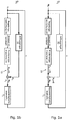
- the control arrangement shown comprises a control device 20 which is connected to a fluid energy machine 10 via a throttle 21.
- the fluid energy machine 10 generates a first torque M A.
- an auxiliary unit 30 is provided, which generates a third torque M H.
- the first torque M A and the third torque M H result in a second torque M W , which is applied to an output shaft 15, which is connected to the fluid energy machine 10.
- the speed n of the output shaft 15 is fed back via a feedback to the control device 20 and the auxiliary unit 30, whereby the control loops close.
- Fig. 1a shows the first and the second control loop in the first method step S 1 .
- the thickly marked lines and objects form the first control loop, which is active in method step S 1 .
- the second control loop is inactive in method step S 2 .
- the first control loop uses the first torque M A as the controlled variable, which is influenced by the position of the throttle 21.
- the first torque M A of the fluid energy machine 10 is regulated from an initial torque M 0 to an intermediate torque M Z. Since the second control loop is not active, the auxiliary unit 30 does not contribute to the control and the third torque M H is zero.
- the second torque M W acting on the output shaft 15 corresponds in the first method step S 1 the first torque M A. Due to the regulation via the throttle 21, the first control loop has a first time constant T 1 .
- Fig. 1b shows the first and the second control loop in the second method step S 2 .
- the thickly marked lines and objects form the second control loop, which is active in method step S 2 .
- the first control loop is no longer active in method step S 2 , but the position of the throttle 21 is kept largely constant.
- the first torque M A which is generated by the fluid energy machine 10, further corresponds to the intermediate torque M I.
- the second control loop uses the speed n of the output shaft 15 as the controlled variable, which is influenced by the auxiliary unit 30.
- the second torque M W corresponds to the intermediate torque M I and the speed n of the output shaft corresponds to the intermediate speed n I.
- the speed n of the output shaft 15 is now regulated from the intermediate speed n I to the target speed nz.
- the auxiliary unit 30 applies the third torque M H , which together with the first torque M A represents the second torque M W on the output shaft 15.
- the auxiliary unit 30 controls the speed n until it corresponds to the target speed nz and can be kept stable by the second control loop.
- the second control loop directly controls the rotational movement of the output shaft 15 without directly influencing the fluid energy machine 10. It is therefore only necessary to take into account the moment of inertia J of the fluid energy machine 10 and the loads connected to it, for example a generator 60.
- the second time constant T 2 of the second control loop is thus significantly less than the first time constant T 1 of the first control loop.
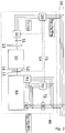
- Fig. 2 shows a detailed embodiment of the control arrangement which is used for a generator 40.
- the fluid energy machine is designed as an internal combustion engine 10.
- the generator 40 shown is used to feed energy into an electrical power supply network 50.
- the power generator 40 comprises a generator 60 which is designed as a synchronous generator.
- the internal combustion engine 10 can be operated in particular with a gaseous fuel, such as biogas.
- the internal combustion engine 10 is regulated via the position of its throttle 21.
- the internal combustion engine 10 has a generator clutch 11, via which the internal combustion engine 10 is connected to the generator 60.
- a speed sensor 12 is arranged, which measures the speed n of the output shaft 15 connected to the internal combustion engine 10.
- the power unit 40 comprises the auxiliary unit 30 configured as an electric auxiliary motor, which is connected via an electric clutch 31 to a flywheel 13 of the internal combustion engine 10 and controls the internal combustion engine 10 in a certain speed range for synchronizing the generator 60 with the electrical power supply network 50.
- the power unit 40 also includes the control device 20, which is designed as a frequency converter and is connected to the electrical auxiliary motor 30 and the electrical energy supply network 50 or another energy source.
- the power unit 40 further comprises a synchronization device 70, which is connected to the electrical power supply network 50, the control device 20 and the generator 60.
- the power unit 40 has a circuit breaker 80, which connects the generator 60 and the electrical power supply network 50 to one another.
- the circuit breaker 80 must therefore be switched off in order to interrupt the connection between the generator 60 and the electrical power supply network 50.
- the Synchronization device 70 monitors the synchronization status and controls the release of the connection between generator 60 and the electrical power supply network 50 via the circuit breaker 80. For this purpose, the synchronization device 70 supplies the circuit breaker 80 with a connection enable signal 72.
- the synchronization device 70 sends the circuit breaker 80 a connection enable signal 72, so that the circuit breaker 80 closes the connection between the generator 60 and the electrical power supply network 50.
- the generator 60 then feeds its energy into the electrical energy supply network 50.
- the internal combustion engine 10 is raised via the throttle 21 to a predetermined tolerance band defined by the target speed n Z of the generator 60.
- the target speed n Z corresponds, for example, to 1300 revolutions per minute.
- the electric auxiliary motor 30 controls the speed n of the internal combustion engine 10, which drives the generator 60.
- the electric auxiliary motor 30 itself is controlled by the control device 20.
- the control device 20 provides the auxiliary motor 30 with a suitable supply voltage UH with a frequency f H.
- the regulation of the control device 20 is based on data from the energy supply network 50 and up to two signals, optionally the speed signal 14 of the speed sensor 12 and absolutely the speed control signal 71 of the synchronization device 70.
- the speed signal 14 forms the current speed n, ie frequency, of the internal combustion engine 10 , also of the generator 60.
- the speed control signal 71 is generated by the synchronization device 70 based on the output 62 of the generator 60 and the data of the electrical power supply network 50 as a relative or absolute speed setpoint specification.
- the data of the electrical energy supply network 50 include the voltage U N , the phase position ⁇ N , the phase sequence and the frequency f N of the electrical energy supply network 50.
- the generator 60 is considered to be synchronized with the electrical power supply network 50 if the voltage U G , the phase position ⁇ G , the phase sequence and the frequency f G of the generator 60 are identical to the voltage U N , the phase position ⁇ N , the phase sequence and the frequency f N of the electrical power supply network 50.
- the voltage and phase sequence are negligible.
- the voltage U G of the generator 60 is regulated by an automatic voltage regulator 61 of the generator 60, which receives the voltage U N of the electrical power supply network 50 and the output voltage U G of the generator 60 as an input.
- the phase sequence is defined by the direction of rotation of the generator.
- the electric auxiliary motor 30 controls the frequency f G , speed n of the generator 60, and the phase position ⁇ G.
- the synchronization can be divided into several time periods A to D.
- the diagram according to Fig. 3 shows on the one hand the synchronization with regulation by the electric auxiliary motor 30 using the solid line and on the other hand the synchronization from the prior art with regulation purely by the throttle 21 using the dashed line.
- period A the internal combustion engine 10 is in starter mode.
- the speed n of the internal combustion engine corresponds to the initial speed n A of approximately 100 revolutions per minute.
- the internal combustion engine 10 is in in period B by regulating the throttle 21 to the intermediate speed n I of approximately 1300 revolutions per minute in accelerates the proximity of the target speed nz of 1500 revolutions per minute. This process takes about 4 seconds.
- the regulation by the electric auxiliary motor 30 begins. This is referred to as the so-called synchronization time ts.
- the speed n of the internal combustion engine 10 is regulated such that the speed n and thus the frequency of the generator 60 corresponds to the target speed nz. This is in Fig. 3 the case at time t 1 .
- the speed n is then regulated with small control pulses such that the phase position ⁇ G of the generator 60 is identical to the phase position ⁇ N of the electrical power supply network 50. Due to the small control time constant of a few hundred microseconds of the electrical frequency converter, the synchronization time t S is only limited by the moment of inertia J of the internal combustion engine 10.
- the synchronization time t S is approximately one second, but can also be significantly lower, for example in the range of 400 milliseconds.
- the voltage U G , the phase position ⁇ G , the phase sequence and the frequency fc of the generator 60 correspond to the voltage U N , the phase position ⁇ N , the phase sequence and the frequency f N of the electrical energy supply network 50.
- the generator 60 has thus been started and synchronized with the electrical power supply network 50 within a switch-on time t A of 8 seconds.
- the synchronization device 70 now sends the activation enable signal 72 to the circuit breaker 80.
- the circuit breaker 80 closes the connection between the generator 60 and the electrical power supply network 50 and the power generator 40 feeds energy into the energy supply network 50.
- the dashed line in time segments C and D shows that the comparatively much slower control with the throttle 21 of the internal combustion engine 10 approaches the target speed nz only comparatively slowly.
- the target speed n Z is only reached significantly later, at time t 1 * in time segment D.
- the regulation of the phase position is then completed at time t 2 *.
- the synchronization time t S * is in the range of 10 to 50 seconds, which leads to a significantly longer switch-on time t E * of 20 to 60 seconds.
- the internal combustion engine 10 is controlled exclusively by the first control loop. In periods C and D, the internal combustion engine 10 is controlled exclusively by the second control loop. However, it is also conceivable for both the first control loop and the second control loop to participate in the control of the internal combustion engine 10 at each of the time segments A to D.
Abstract
Verfahren zum Regeln einer Fluidenergiemaschine (10), mittels der Energie in mechanische Arbeit umgewandelt wird und die eine Drehbewegung mit einem ersten Drehmoment (M<sub>A</sub>) erzeugt und die mit einer Ausgangswelle (15), an der ein zweites Drehmoment (M<sub>W</sub>) bei einer Drehzahl (n) anliegt, verbunden ist, gekennzeichnet durch folgende Verfahrensschritte:Regeln des ersten Drehmoments (M<sub>A</sub>) in einem ersten Verfahrensschritt (S<sub>1</sub>) mittels einer Regelungsvorrichtung (20) derart, dass das zweite Drehmoment (M<sub>W</sub>) auf eine vorbestimmtes Zwischendrehmoment (M<sub>I</sub>) bei einer Zwischendrehzahl (ni) eingestellt wird, wobei die Fluidenergiemaschine (10) und die Regelungsvorrichtung (20) einen ersten Regelkreis mit einer ersten Zeitkonstante (T<sub>1</sub>) bilden;Regeln der Drehzahl (n) der Ausgangswelle (15) in einem zweiten Verfahrensschritt (S<sub>2</sub>) mittels eines Hilfsaggregats (30) derart, dass die Drehzahl (n) von der Zwischendrehzahl (ni) auf eine vorbestimmte Zieldrehzahl (nz) eingestellt wird, wobei ein sich an der Ausgangswelle (15) ergebendes Massenträgheitsmoment (J) und das Hilfsaggregat (30) einen zweiten Regelkreis mit einer zweiten Zeitkonstante (T<sub>2</sub>) bilden und wobei die zweite Zeitkonstante (T<sub>2</sub>) geringer ist als die erste Zeitkonstante (T<sub>1</sub>).Method for regulating a fluid energy machine (10) by means of which energy is converted into mechanical work and which produces a rotary movement with a first torque (M <sub> A </sub>) and with an output shaft (15) on which a second Torque (M <sub> W </sub>) is present at a speed (n), is connected, characterized by the following method steps: Regulation of the first torque (M <sub> A </sub>) in a first method step (S < sub> 1 </sub>) by means of a control device (20) in such a way that the second torque (M <sub> W </sub>) reaches a predetermined intermediate torque (M <sub> I </sub>) at an intermediate speed ( ni) is set, the fluid energy machine (10) and the control device (20) forming a first control loop with a first time constant (T <sub> 1 </sub>); control of the speed (n) of the output shaft (15) in one second method step (S <sub> 2 </sub>) by means of an auxiliary unit (30) such that the speed (s) depends on the intermediate speed (ni) is set to a predetermined target speed (nz), a mass moment of inertia (J) resulting on the output shaft (15) and the auxiliary unit (30) having a second control loop with a second time constant (T <sub> 2 </sub> ) and the second time constant (T <sub> 2 </sub>) is less than the first time constant (T <sub> 1 </sub>).
Description
Die Erfindung betrifft ein Verfahren zum Regeln einer Fluidenergiemaschine und eine Regelungsanordnung, die insbesondere zum Durchführen des Verfahrens dient. Die Fluidenergiemaschine findet bevorzugt für ein Stromaggregat zur Einspeisung von insbesondere aus gasförmigen Brennstoffen wie Biogas gewonnener Energie in ein elektrisches Energieversorgungsnetz Anwendung.The invention relates to a method for regulating a fluid energy machine and a regulating arrangement which is used in particular to carry out the method. The fluid energy machine is preferably used for a power unit for feeding energy obtained in particular from gaseous fuels such as biogas into an electrical power supply network.
Ein elektrisches Energieversorgungsnetz im Sinne der vorliegenden Erfindung ist ein Stromnetz, das in der elektrischen Energietechnik der Versorgung von Verbrauchern mit elektrischer Energie dient. Ein Stromnetz ist ein Netzwerk aus elektrischen Stromleitungen, insbesondere Freileitungen und Erdkabeln, die insbesondere Einrichtungen wie Kraftwerke und andere Energieumwandler, beispielsweise Windenergie- und Photovoltaikanlagen, daran angeschlossene Schalt- und Umspannwerke und die Verbraucher miteinander verbinden.An electrical power supply network in the sense of the present invention is a power network that serves to supply consumers with electrical energy in electrical power engineering. A power network is a network of electrical power lines, in particular overhead lines and underground cables, which in particular connect facilities such as power plants and other energy converters, for example wind energy and photovoltaic systems, switchgear and transformer stations connected to them and the consumers.
Das elektrische Energieversorgungsnetz kann als sogenanntes Verbundnetz ausgestaltet sein, das sich in der Regel aus großen, räumlich benachbarten und elektrisch verbundenen Stromnetzen, die eine Vielzahl von Kraftwerken und Verbrauchern umfassen, zusammensetzt. Das elektrische Energieversorgungsnetz kann jedoch auch als sogenanntes Inselnetz ausgestaltet sein, also als ein lokal abgegrenztes Stromnetz, das ein räumlich enges Gebiet versorgt und keinen direkten elektrischen Anschluss zu anderen Stromnetzen hat.The electrical power supply network can be designed as a so-called interconnected network, which is generally composed of large, spatially adjacent and electrically connected power networks, which comprise a large number of power plants and consumers. However, the electrical power supply network can also be configured as a so-called island network, that is to say as a locally delimited power network that supplies a spatially narrow area and has no direct electrical connection to other power networks.
Bekannt sind Stromaggregate zur Einspeisung von Energie in ein elektrisches Energieversorgungsnetz, bei denen die Energie aus gasförmigen Brennstoffen gewonnene wird. Als gasförmiger Brennstoff eignet sich beispielsweise Biogas, ein brennbares Gas, das durch Vergärung von Biomasse entsteht. Biogas wird üblicherweise in Biogasanlagen hergestellt, mittels denen biologische Abfälle und nachwachsende Rohstoffe vergoren werden.Electricity generators for feeding energy into an electrical power supply network are known, in which the energy is obtained from gaseous fuels. For example, biogas, a combustible gas that is produced by fermentation of biomass, is suitable as a gaseous fuel. Biogas is usually produced in biogas plants, which are used to ferment biological waste and renewable raw materials.
Ein solches Stromaggregat umfasst üblicherweise einen Generator, der insbesondere als Synchrongenerator ausgestaltet ist, und eine in der Regel als Verbrennungskraftmaschine ausgestaltete Fluidenergiemaschine, die den Generator antreibt. Durch die Verbrennungskraftmaschine wird die chemische Energie des Brennstoffes, etwa eines Gases wie beispielsweise Biogas, Holzgas, Grubengas, Erdgas oder Propan, in kinetische Energie umgewandelt, mit welcher der Generator dann angetrieben wird. Der Generator wandelt die kinetische Energie in elektrische Energie um, die in das Energieversorgungsnetz eingespeist wird.Such a power unit usually comprises a generator, which is designed in particular as a synchronous generator, and a fluid energy machine, which is generally designed as an internal combustion engine, and which drives the generator. The internal combustion engine converts the chemical energy of the fuel, for example a gas such as biogas, wood gas, mine gas, natural gas or propane, into kinetic energy, with which the generator is then driven. The generator converts the kinetic energy into electrical energy, which is fed into the energy supply network.
Ist der Generator des Stromaggregats ein Synchrongenerator, so muss der Generator mit dem elektrischen Energieversorgungsnetz synchronisiert werden, bevor Energie von dem Stromaggregat in das elektrische Energieversorgungsnetz eingespeist werden kann.If the generator of the power unit is a synchronous generator, the generator must be synchronized with the electrical power supply network before energy can be fed into the electrical power supply network from the power unit.
Gewöhnlich wird eine Regelgröße, wie etwa die Drehzahl oder das Drehmoment, bei einer Fluidenergiemaschine über einen einzigen Regelkreis geregelt. Ein Beispiel hierfür ist aus
Ein Regelkreis besteht grundsätzlich aus einer Regelstrecke, einem Stellglied, einem Regler und einer Rückführung, die in einem geschlossenen Kreis miteinander verbunden sind. Die Regelstrecke wird über das Stellglied durch den Regler geregelt. Die Regelung des Reglers selbst basiert auf einer Regelgröße, welche von der Regelstrecke zurückgeführt wird. Somit kann der Regler die Regelstrecke immer basierend auf einem aktuellen Ausgangswert der Regelstrecke nachregeln.A control loop basically consists of a controlled system, an actuator, a controller and a feedback, which are connected to each other in a closed loop. The controlled system is controlled by the controller via the actuator. The control of the controller itself is based on a controlled variable which is fed back from the controlled system. Thus, the controller can always readjust the controlled system based on a current output value of the controlled system.
Bei einem einzigen Regelkreis regelt der Regler üblicherweise den gesamten Wertebereich einer Regelgröße. Regelkreise, die über vergleichsweise weite Wertebereiche regeln können, und das optimaler Weise in einer vertretbaren Zeit, weisen vergleichsweise hohe Zeitkonstanten auf.With a single control loop, the controller usually controls the entire value range of a control variable. Control loops that can regulate over comparatively wide value ranges, and optimally in a reasonable time, have comparatively high time constants.
Die Zeitkonstante des Regelkreises bildet die Verzögerungszeiten im Regelkreis ab. Weist ein Regelkreis hohe Verzögerungszeiten auf, neigt der Regelkreis dazu, beim Regeln auf einen vorgegebenen Wert der Regelgröße diesen zu durchfahren. Dieser Effekt wird Überschwingen genannt. Der Regler muss daraufhin die Regelgröße wieder herunterregeln. Als Überschwingen ist somit zu verstehen, dass in einem Regelkreis aufgrund von unvermeidbaren Verzögerungszeiten, welche durch die Zeitkonstante abgebildet werden, beim Regeln der Regelgröße der Zielwert durchfahren wird und der Regelkreis somit überschwingt. Erst durch eine immer präziser werdende Regelung, dem sogenannten Ausregeln, kann der Zielwert stabil erreicht werden. In einem umgedrehten Regelkreis kann es ebenso zu einem Unterschwingen kommen.The time constant of the control loop shows the delay times in the control loop. If a control loop has long delay times, the control loop tends to run through it when controlling to a predetermined value of the controlled variable. This effect is called overshoot. The controller must then Reduce the controlled variable again. Overshoot is therefore to be understood to mean that, in a control loop, due to unavoidable delay times, which are represented by the time constant, the target value is passed when regulating the controlled variable and the control loop thus overshoots. The target value can only be achieved in a stable manner by means of regulation that is becoming more and more precise. Undershoot can also occur in an upside-down control loop.
Regelkreise mit vergleichsweise hohen Zeitkonstanten, die häufig bei mechanischen Stellgrößen auftreten, zeichnen sich durch besonders hohes Überschwingen aus. Das Ausregeln der Fluidenergiemaschinen wird damit vergleichsweise aufwendig.Control loops with comparatively high time constants, which often occur with mechanical manipulated variables, are characterized by particularly high overshoot. The regulation of the fluid energy machines is comparatively complex.
Aus
Ein Verfahren zum Betrieb einer Windenergieanlage offenbart
Der Erfindung liegt die Aufgabe zugrunde, ein Verfahren zum Regeln einer Fluidenergiemaschine und eine Regelungsanordnung, die sich insbesondere zum Durchführen des Verfahrens eignet, zur Verfügung zu stellen, die eine vergleichsweise schnelle und genaue Regelung ermöglichen.The invention is based on the object of making available a method for regulating a fluid energy machine and a regulating arrangement which is particularly suitable for carrying out the method, which enable comparatively fast and precise regulation.
Die Aufgabe wird durch ein Verfahren nach Anspruch 1 und eine Regelungsanordnung nach Anspruch 6 gelöst. Bevorzugte Ausgestaltungen des Verfahrens finden ihren Niederschlag in den Ansprüchen 1 bis 5, und bevorzugte Ausgestaltungen der Regelungsanordnung finden ihren Niederschlag in den Ansprüchen 7 bis 14.The object is achieved by a method according to
Das erfindungsgemäße Verfahren zum Regeln einer Fluidenergiemaschine, mittels der Energie in mechanische Arbeit umgewandelt wird und die eine Drehbewegung mit einem ersten Drehmoment erzeugt und die mit einer Ausgangswelle, an der ein zweites Drehmoment bei einer Drehzahl anliegt, verbunden ist, umfasst die folgenden Verfahrensschritte:
Regeln des ersten Drehmoments in einem ersten Verfahrensschritt mittels einer Regelungsvorrichtung derart, dass das zweite Drehmoment auf ein vorbestimmtes Zwischendrehmoment bei einer Zwischendrehzahl eingestellt wird, wobei die Fluidenergiemaschine und die Regelungsvorrichtung einen ersten Regelkreis mit einer ersten Zeitkonstante bilden;The method according to the invention for regulating a fluid energy machine, by means of which energy is converted into mechanical work and which generates a rotary movement with a first torque and which is connected to an output shaft to which a second torque is applied at a speed, comprises the following method steps:
Controlling the first torque in a first method step by means of a control device such that the second torque is set to a predetermined intermediate torque at an intermediate speed, the fluid energy machine and the control device forming a first control loop with a first time constant;
Regeln der Drehzahl der Ausgangswelle in einem zweiten Verfahrensschritt mittels eines Hilfsaggregats derart, dass die Drehzahl von der Zwischendrehzahl auf eine vorbestimmte Zieldrehzahl eingestellt wird, wobei ein sich an der Ausgangswelle ergebenes Massenträgheitsmoment und das Hilfsaggregat einen zweiten Regelkreis mit einer zweiten Zeitkonstante bilden und wobei die zweite Zeitkonstante geringer ist als die erste Zeitkonstante.Controlling the speed of the output shaft in a second method step using an auxiliary unit such that the speed is set from the intermediate speed to a predetermined target speed, a mass moment of inertia resulting on the output shaft and the auxiliary unit forming a second control loop with a second time constant, and the second Time constant is less than the first time constant.
Im vorliegenden Fall ist als Regelstrecke das Massenträgheitsmoment der Fluidenergiemaschine zu verstehen. Jegliche mit der Fluidenergiemaschine gekoppelte Last, beispielsweise ein Generator, trägt zum Massenträgheitsmoment bei, das heißt bestimmt die Charakteristik der Regelstrecke.In the present case, the control system is to be understood as the moment of inertia of the fluid energy machine. Any load coupled to the fluid energy machine, for example a generator, contributes to the moment of inertia, that is to say determines the characteristic of the controlled system.
Um die Fluidenergiemaschine auf die Zieldrehzahl zu regeln, wird die Fluidenergiemaschine durch Stellglieder geregelt, welche wiederum von einem Regler, also der Regelungsvorrichtung oder dem Hilfsaggregat, geregelt werden. Die aktuelle Drehzahl der Ausgangswelle, die Bestandteil der Fluidenergiemaschine oder ein separates Bauteil sein kann, steht dem Regler zur Verfügung. Je nachdem ob der Regler die Regelungsvorrichtung oder das Hilfsaggregat verwendet, wirkt der erste oder der zweite Regelkreis. Als Regelgrößen sind das erste Drehmoment der Fluidenergiemaschine im ersten Regelkreis und die Drehzahl der Ausgangswelle im zweiten Regelkreis vorgesehen.In order to regulate the fluid energy machine to the target speed, the fluid energy machine is regulated by actuators, which in turn are regulated by a regulator, that is to say the regulating device or the auxiliary unit. The current speed of the output shaft, which can be part of the fluid energy machine or a separate component, is available to the controller. Depending on whether the controller uses the control device or the auxiliary unit, the first or the second control loop acts. The first torque are the controlled variables the fluid energy machine in the first control loop and the speed of the output shaft in the second control loop.
Als Ausregeln der Fluidenergiemaschine ist somit der Regelungsvorgang zu verstehen, wenn die Fluidenergiemaschine von einer aktuellen Drehzahl auf eine vorher bestimmte Zieldrehzahl geregelt wird und das Überschwingen solange geregelt wird, bis die Fluidenergiemaschine die Zieldrehzahl stabil hält.The regulation process is to be understood as the regulation of the fluid energy machine if the fluid energy machine is regulated from a current speed to a previously determined target speed and the overshoot is regulated until the fluid energy machine keeps the target speed stable.
Aufgrund der im Vergleich zu der ersten Zeitkonstante des ersten Regelkreises niedrigeren zweiten Zeitkonstante des zweiten Regelkreises fällt ein Überschwingen des Regelkreises beim Ausregeln der Fluidenergiemaschine weniger stark aus.Due to the lower second time constant of the second control loop compared to the first time constant of the first control loop, overshoot of the control loop is less pronounced when the fluid energy machine is adjusted.
Der zweite Regelkreis regelt die Drehzahl von der Zwischendrehzahl auf die Zieldrehzahl somit schneller als dies der erste Regelkreis in gleichem Maße über die Regelgröße des ersten Drehmoments erreichen könnte. Auf diese Weise wird nicht nur eine zuverlässigere, sondern auch eine schnellere und präzisere Regelung ermöglicht.The second control loop regulates the speed from the intermediate speed to the target speed faster than the first control loop could achieve to the same extent via the control variable of the first torque. In this way, not only a more reliable, but also a faster and more precise control is made possible.
Zweckmäßigerweise fungiert die Regelungsvorrichtung als Stellglied für den ersten Regelkreis, wobei vorzugsweise die Regelungsvorrichtung eine Drossel als Stellglied umfasst. Eine Drossel eignet sich besonders gut als Stellglied, da sie eine einfache, effiziente Ausführung eines Stellglieds darstellt. Je nach Stellung der Drossel kann direkt die Menge des Fluids, mit welchem die Fluidenergiemaschine betrieben wird, geregelt werden. Der auf insbesondere der Drossel und der Fluidenergiemaschine basierende Regelkreis weist jedoch eine vergleichsweise hohe erste Zeitkonstante auf, was sich nachteilig bei einer präzisen Regelung, insbesondere beim Ausregeln der Fluidenergiemaschine, auswirkt.The control device expediently functions as an actuator for the first control circuit, the control device preferably comprising a throttle as an actuator. A throttle is particularly well suited as an actuator because it represents a simple, efficient design of an actuator. Depending on the position of the throttle, the amount of fluid with which the fluid energy machine is operated can be regulated directly. However, the control loop, which is based in particular on the throttle and the fluid energy machine, has a comparatively high first time constant, which has a disadvantageous effect in the case of precise control, in particular when regulating the fluid energy machine.
Vorteilhaft fungiert das Hilfsaggregat als Stellglied für den zweiten Regelkreis. Das Hilfsaggregat und die Regelungsvorrichtung können als eine gemeinsame Vorrichtung ausgebildet sein, welche die zwei unterschiedlichen Stellglieder umfasst.The auxiliary unit advantageously functions as an actuator for the second control loop. The auxiliary unit and the control device can be designed as a common device which comprises the two different actuators.
Bevorzugt wird in dem ersten Verfahrensschritt das erste Drehmoment ausschließlich mittels der Regelungsvorrichtung geregelt und in dem zweiten Verfahrensschritt die Drehzahl ausschließlich mittels des Hilfsaggregats geregelt.In the first method step, the first torque is preferably regulated exclusively by means of the control device and in the second method step the speed is regulated exclusively by means of the auxiliary unit.
Der erste und der zweite Regelkreis unterscheiden sich vor allem in den unterschiedlichen Zeitkonstanten. Ein Regelkreis mit hoher Zeitkonstante weist zwar Vorteile beim groben Regeln von großen Wertebereichen der Regelgröße auf, ist allerdings aufgrund des hohen Überschwingens nachteilig bei präzisen Regelungen. Dem hingegen zeichnet sich ein Regelkreis mit niedriger Zeitkonstante durch eine besonders präzise Regelung aus, ist aber nachteilig beim Regeln großer Wertebereiche der Regelgröße. Deshalb hat es sich als vorteilhaft erwiesen, die Drehzahl über das erste Drehmoment in dem ersten Regelkreis ausschließlich mittels der Regelvorrichtung zu regeln, um die Vorteile bei großen Wertebereichen der Regelgröße auszunutzen, und in dem zweiten Regelkreis die Drehzahl ausschließlich mittels des Hilfsaggregats zu regeln, um die Vorteile einer präzisen Regelung auszunutzen.The first and the second control loop differ mainly in the different time constants. A control loop with a high time constant has advantages for rough control of large value ranges of the controlled variable, but is disadvantageous for precise controls due to the high overshoot. In contrast, a control loop with a low time constant is characterized by a particularly precise control, but is disadvantageous when controlling large ranges of values of the controlled variable. It has therefore proven to be advantageous to control the speed via the first torque in the first control loop exclusively by means of the control device in order to take advantage of large value ranges of the controlled variable, and to control the speed in the second control loop exclusively by means of the auxiliary unit in order to to take advantage of precise regulation.
Die Zwischendrehzahl kann in einem Toleranzband um die Zieldrehzahl liegen. Diese muss im Allgemeinen jedoch nicht stabil gehalten, sondern nur punktuell erreicht werden. Als zweckmäßig hat es sich erwiesen, wenn die Zwischendrehzahl in einem Bereich zwischen 60% und 140% der Zieldrehzahl liegt. Vorzugsweise liegt die Zwischendrehzahl in einem Bereich zwischen 80% und 120% der Zieldrehzahl. Liegt die Zieldrehzahl beispielsweise bei ca. 1500 Umdrehungen pro Minute (U/min), dann kann sich die Zwischendrehzahl in einem Bereich zwischen 900 U/min (60%) bis 2100 U/min (140%) bewegen. Bevorzugt bewegt sich die Zwischendrehzahl in einem Bereich zwischen 1200 U/min (80%) und 1800 U/min (120%).The intermediate speed can be within a tolerance band around the target speed. In general, however, this does not have to be kept stable, but only to be achieved selectively. It has proven to be expedient if the intermediate speed is in a range between 60% and 140% of the target speed. The intermediate speed is preferably in a range between 80% and 120% of the target speed. For example, if the target speed is approximately 1500 revolutions per minute (rpm), the intermediate speed can range between 900 rpm (60%) and 2100 rpm (140%). The intermediate speed preferably ranges between 1200 rpm (80%) and 1800 rpm (120%).
Zum Ausnutzen der einzelnen Vorteile der Regelkreise mit niedriger und hoher Zeitkonstante wird ein großer Teil der zu regelnden Drehzahl über das erste Drehmoment durch den ersten Regelkreis mit hoher Zeitkonstante geregelt, und zwar bis das Zwischendrehmoment erreicht ist. Danach setzt die Regelung durch den zweiten Regelkreis mit niedriger Zeitkonstante ein, um die Drehzahl der Ausgangswelle von der Zwischendrehzahl, welche sich durch das Zwischendrehmoment einstellt, auf die Zieldrehzahl zu regeln.In order to take advantage of the individual advantages of the control loops with a low and high time constant, a large part of the speed to be controlled is controlled by the first torque loop by the first control loop with a high time constant until the intermediate torque is reached. Thereafter, the control by the second control loop with a low time constant starts to change the speed of the Output shaft to regulate from the intermediate speed, which is established by the intermediate torque, to the target speed.
Die erfindungsgemäße Regelungsanordnung dient insbesondere zum Durchführen des Verfahrens und umfasst eine Fluidenergiemaschine zum Umwandeln von Energie in mechanische Arbeit, die eine Drehbewegung mit einem ersten Drehmoment erzeugt und die mit einer Ausgangswelle, an der ein zweites Drehmoment bei einer Drehzahl anliegt, verbunden ist. Die Regelungsanordnung umfasst ferner eine Regelungsvorrichtung zum Regeln des ersten Drehmoments derart, dass das zweite Drehmoment auf ein vorbestimmtes Zwischendrehmoment bei einer Zwischendrehzahl eingestellt wird. Die Fluidenergiemaschine und die Regelungsvorrichtung bilden einen ersten Regelkreis mit einer ersten Zeitkonstante. Die Regelungsanordnung umfasst zudem ein Hilfsaggregat zum Regeln der Drehzahl der Ausgangswelle derart, dass die Drehzahl von der Zwischendrehzahl auf eine vorbestimmte Zieldrehzahl eingestellt wird. Ein sich an der Ausgangswelle ergebenes Massenträgheitsmoment und das Hilfsaggregat bilden einen zweiten Regelkreis mit einer zweiten Zeitkonstante.The control arrangement according to the invention is used in particular to carry out the method and comprises a fluid energy machine for converting energy into mechanical work, which generates a rotary movement with a first torque and which is connected to an output shaft, to which a second torque is applied at a speed. The control arrangement further comprises a control device for controlling the first torque in such a way that the second torque is set to a predetermined intermediate torque at an intermediate speed. The fluid energy machine and the control device form a first control loop with a first time constant. The control arrangement also includes an auxiliary unit for controlling the speed of the output shaft in such a way that the speed is set from the intermediate speed to a predetermined target speed. A moment of inertia resulting on the output shaft and the auxiliary unit form a second control loop with a second time constant.
Der zweite Regelkreis wirkt direkt auf die Rotationsbewegung der Ausgangswelle, ohne auf die Fluidenergiemaschine unmittelbar Einfluss zu nehmen. Es muss als Zeitkonstante nicht mehr die Regelungszeitkonstante der Fluidenergiemaschine, sondern lediglich das Massenträgheitsmoment, das sich insbesondere durch die Fluidenergiemaschine und die angeschlossene Last, etwa ein Generator, an der Ausgangswelle ergibt, als Zeitkonstante berücksichtigt werden. Faktoren für die Regelungszeitkonstante der Fluidenergiemaschine sind beispielsweise Drücke, Volumenströme, sonstige Regler der Fluidenergiemaschine oder die Regelung beeinflussende Dimensionen von Teilen der Fluidenergiemaschine. Diese zweite Zeitkonstante ist wesentlich geringer als die erste Zeitkonstante.The second control loop acts directly on the rotational movement of the output shaft without directly influencing the fluid energy machine. The time constant no longer has to be taken into account as the control time constant of the fluid energy machine, but only the moment of inertia, which results in particular from the fluid energy machine and the connected load, for example a generator, on the output shaft as a time constant. Factors for the control time constant of the fluid energy machine are, for example, pressures, volume flows, other controllers of the fluid energy machine or dimensions of parts of the fluid energy machine that influence the control. This second time constant is significantly less than the first time constant.
Vorteilhaft ist die Fluidenergiemaschine als eine Wärmekraftmaschine, insbesondere Verbrennungskraftmaschine, Dampfmaschine, Dampfturbine oder Gasturbine, oder als ein Hydraulikmotor ausgebildet.The fluid energy machine is advantageously designed as a heat engine, in particular an internal combustion engine, steam engine, steam turbine or gas turbine, or as a hydraulic motor.
Vorteilhaft ist das Hilfsaggregat als Elektromotor, insbesondere als Gleichstrommotor oder als Asynchronmotor oder als Synchron-Reluktanzmotor, ausgebildet.The auxiliary unit is advantageously designed as an electric motor, in particular as a DC motor or as an asynchronous motor or as a synchronous reluctance motor.
Als vorteilhaft hat es sich zudem erwiesen, wenn das Hilfsaggregat als mechanische Bremsvorrichtung ausgebildet ist, die vorzugsweise auf der Ausgangswelle angeordnet ist, um insbesondere durch Umwandlung von Rotationsenergie in Wärme die Drehzahl der Ausgangswelle zu reduzieren.It has also proven to be advantageous if the auxiliary unit is designed as a mechanical braking device, which is preferably arranged on the output shaft, in order to reduce the speed of the output shaft, in particular by converting rotational energy into heat.
Vorteilhaft fungiert die Regelungsvorrichtung als Stellglied für den ersten Regelkreis, wobei vorzugsweise die Regelungsvorrichtung eine Drossel als Stellglied aufweist. Vorteilhaft fungiert das Hilfsaggregat als Stellglied für den zweiten Regelkreis.The control device advantageously functions as an actuator for the first control circuit, the control device preferably having a throttle as an actuator. The auxiliary unit advantageously functions as an actuator for the second control loop.
Vorteilhaft umfasst die Regelungsanordnung einen Generator, insbesondere Synchrongenerator, wobei bevorzugt die Fluidenergiemaschine den Generator antreibt. Hierdurch wird die chemische Energie der Fluidenergiemaschine in kinetische Energie umgewandelt, welche den Generator antreibt. Der Generator kann mit einem elektrischen Energieversorgungsnetz verbunden sein, um die von dem Generator erzeugte Energie in das elektrische Energieversorgungsnetz einzuspeisen.The control arrangement advantageously comprises a generator, in particular a synchronous generator, the fluid energy machine preferably driving the generator. This converts the chemical energy of the fluid energy machine into kinetic energy that drives the generator. The generator can be connected to an electrical power supply network in order to feed the energy generated by the generator into the electrical power supply network.
Vorteilhaft wird die Drehzahl der Ausgangswelle derart geregelt, dass bei der Zieldrehzahl der Generator mit dem elektrischen Energieversorgungsnetz synchronisiert ist. Synchronisierung bedeutet, dass das Drehfeld des Generators und das Drehfeld des elektrischen Energieversorgungsnetzes vor der Zuschaltung des Generators an das elektrische Energieversorgungsnetz synchron verlaufend gemacht werden, das heißt, dass insbesondere Spannung, Phasenlage, Phasenfolge und Frequenz des Generators und des elektrischen Energieversorgungsnetzes identisch sind. Die Frequenz des Generators wird durch dessen Drehzahl abgebildet.The speed of the output shaft is advantageously regulated in such a way that the generator is synchronized with the electrical power supply network at the target speed. Synchronization means that the rotating field of the generator and the rotating field of the electrical energy supply network are made to run synchronously before the generator is connected to the electrical energy supply network, that is to say that in particular the voltage, phase position, phase sequence and frequency of the generator and the electrical energy supply network are identical. The frequency of the generator is represented by its speed.
Der Generator, insbesondere in der Ausgestaltung als Synchrongenerator, verfügt bereits vor dem sogenannten Netzparallelbetrieb, bei dem der Generator mit dem elektrischen Netz synchronisiert ist, über ein elektrisches Inselnetz, das an Klemmen des Generators anliegt. Dieses Inselnetz hat eine eigene Frequenz, die sich durch die Drehzahl der Fluidenergiemaschine ergibt. Andererseits wird die Frequenz des Inselnetzes über die angeschlossenen Lasten definiert. Werden also bei gleicher Leistung der Fluidenergiemaschine elektrische Lasten zugeschaltet, verringert sich die Drehzahl. Daher hat es sich als vorteilhaft erwiesen, wenn das Hilfsaggregat als elektrische Last auf dem zu synchronisierenden Inselnetz der Fluidenergiemaschine ausgebildet ist, die insbesondere regelbar oder stufenweise zu- und abschaltbar ist.The generator, in particular in the form of a synchronous generator, already has what is known as network parallel operation, in which the generator with the electrical network is synchronized via an electrical island network, which is connected to terminals of the generator. This island grid has its own frequency, which results from the speed of the fluid energy machine. On the other hand, the frequency of the island grid is defined via the connected loads. If electrical loads are switched on for the same power of the fluid energy machine, the speed is reduced. It has therefore proven to be advantageous if the auxiliary unit is designed as an electrical load on the island network of the fluid energy machine to be synchronized, which can be switched on and off in particular in a controllable manner or in stages.
Vorteilhafterweise findet die Fluidenergiemaschine für ein Stromaggregat zur Einspeisung von insbesondere aus gasförmigen Brennstoffen wie Biogas gewonnener Energie in ein elektrisches Energieversorgungsnetz Anwendung. Zu diesem Zweck kann die zweckmäßigerweise als Verbrennungskraftmaschine ausgestaltete Fluidenergiemaschine in einem anfänglichen Zeitabschnitt der Einschaltzeit den Generator auf eine Drehzahl in einem vorgegebenen Toleranzband um die Synchrondrehzahl beschleunigen. Ein Hilfsmotor regelt während einem abschließenden Zeitabschnitt der Einschaltzeit, der sogenannten Synchronisierungszeit, die Drehzahl der Verbrennungskraftmaschine in dem Toleranzband um die Synchrondrehzahl derart, dass am Ende der Synchronisierungszeit die Drehzahl des Generators der Synchrondrehzahl entspricht und zumindest auch die Phasenlage des Generators identisch mit der Phasenlage des elektrischen Energieversorgungsnetzes ist.The fluid energy machine is advantageously used for a power generator for feeding energy obtained in particular from gaseous fuels such as biogas into an electrical power supply network. For this purpose, the fluid energy machine, which is expediently designed as an internal combustion engine, can accelerate the generator to a speed in a predetermined tolerance band around the synchronous speed in an initial time period of the switch-on time. An auxiliary motor controls the speed of the internal combustion engine in the tolerance band around the synchronous speed during a final period of the switch-on time, the so-called synchronization time, such that at the end of the synchronization time the speed of the generator corresponds to the synchronous speed and at least the phase position of the generator is identical to the phase position of the electrical power supply network.
Ein Ausführungsbeispiel der Erfindung wird im Folgenden anhand der beigefügten Zeichnungen näher erläutert. Darin zeigen:
- Fig. 1a
- ein schematisches Schaltbild des ersten Regelkreises und des zweiten Regelkreises im ersten Verfahrensschritt;
- Fig. 1b
- ein schematisches Schaltbild des ersten Regelkreises und des zweiten Regelkreises im zweiten Verfahrensschritt;
- Fig. 2
- ein schematisches Schaltbild der Fluidenergiemaschine und eines elektrischen Energieversorgungsnetzes; und
- Fig. 3
- ein Diagramm der Drehzahl der Fluidenergiemaschine über die Zeit während des Synchronisierungsvorgangs mit dem elektrischen Energieversorgungsnetz.
- Fig. 1a
- a schematic circuit diagram of the first control circuit and the second control circuit in the first method step;
- Fig. 1b
- a schematic circuit diagram of the first control circuit and the second control circuit in the second method step;
- Fig. 2
- a schematic diagram of the fluid energy machine and an electrical power supply network; and
- Fig. 3
- a diagram of the speed of the fluid energy machine over time during the synchronization process with the electrical power supply network.
Der erste Regelkreis benutzt als Regelgröße das erste Drehmoment MA, welches durch die Stellung der Drossel 21 beeinflusst wird. Das erste Drehmoment MA der Fluidenergiemaschine 10 wird von einem Anfangsdrehmoment M0 auf ein Zwischendrehmoment MZ geregelt. Da der zweite Regelkreis nicht aktiv ist, trägt das Hilfsaggregat 30 nichts zur Regelung bei und das dritte Drehmoment MH ist null. Somit entspricht das auf die Ausgangswelle 15 wirkende zweite Drehmoment MW im ersten Verfahrensschritt S1 dem ersten Drehmoment MA. Aufgrund der Regelung über die Drossel 21 weist der erste Regelkreis eine erste Zeitkonstante T1 auf.The first control loop uses the first torque M A as the controlled variable, which is influenced by the position of the
Der zweite Regelkreis benutzt als Regelgröße die Drehzahl n der Ausgangswelle 15, welche über das Hilfsaggregat 30 beeinflusst wird. Nach Abschluss des ersten Verfahrensschritts S1 entspricht das zweite Drehmoment MW dem Zwischendrehmoment MI und die Drehzahl n der Ausgangswelle entspricht der Zwischendrehzahl nI.The second control loop uses the speed n of the
Die Drehzahl n der Ausgangswelle 15 wird nun von der Zwischendrehzahl nI auf die Zieldrehzahl nz geregelt. Hierzu bringt das Hilfsaggregat 30 das dritte Drehmoment MH auf, welches zusammen mit dem ersten Drehmoment MA das zweite Drehmoment MW an der Ausgangswelle 15 darstellt. Das Hilfsaggregat 30 regelt die Drehzahl n solange, bis sie der Zieldrehzahl nz entspricht und vom zweiten Regelkreis stabil gehalten werden kann.The speed n of the
Der zweite Regelkreis regelt direkt die Rotationsbewegung der Ausgangswelle 15, ohne auf die Fluidenergiemaschine 10 unmittelbar Einfluss zu nehmen. Es muss also lediglich das Massenträgheitsmoment J der Fluidenergiemaschine 10 und daran angeschlossene Lasten, also etwa ein Generator 60, berücksichtigt werden. Die zweite Zeitkonstante T2 des zweiten Regelkreises ist somit wesentlich geringer als die erste Zeitkonstante T1 des ersten Regelkreises.The second control loop directly controls the rotational movement of the
Die Verbrennungskraftmaschine 10 weist eine Generatorkupplung 11 auf, über welche die Verbrennungskraftmaschine 10 mit dem Generator 60 verbunden ist. Am Ausgang der Verbrennungskraftmaschine 10, beispielsweise auf dem Zahnkranz der Schwungmasse, ist ein Drehzahlsensor 12 angeordnet, der die Drehzahl n der mit der Verbrennungskraftmaschine 10 verbundenen Ausgangswelle 15 misst.The
Zusätzlich umfasst das Stromaggregat 40 das als elektrischer Hilfsmotor ausgestaltete Hilfsaggregat 30, das über eine Elektrokupplung 31 mit einer Schwungscheibe 13 der Verbrennungskraftmaschine 10 verbunden ist und die Verbrennungskraftmaschine 10 in einem bestimmten Drehzahlbereich zur Synchronisierung des Generators 60 mit dem elektrischen Energieversorgungsnetz 50 regelt.In addition, the
Das Stromaggregat 40 umfasst zudem die Regelvorrichtung 20, die als Frequenzumrichter ausgebildet ist, und mit dem elektrischen Hilfsmotor 30 und dem elektrischen Energieversorgungsnetz 50 oder einer anderen Energiequelle verbunden ist. Weiter umfasst das Stromaggregat 40 eine Synchronisierungsvorrichtung 70, die mit dem elektrischen Energieversorgungsnetz 50, der Regelvorrichtung 20 und dem Generator 60 verbunden ist.The
Außerdem weist das Stromaggregat 40 einen Leistungsschalter 80 auf, der den Generator 60 und das elektrische Energieversorgungsnetz 50 miteinander verbindet. Solange das Stromaggregat 40 nicht mit dem elektrischen Energieversorgungsnetz 50 synchronisiert ist, darf der Generator 60 nicht mit dem elektrischen Energieversorgungsnetz 50 verbunden sein. Der Leistungsschalter 80 muss demnach ausgeschaltet sein, um die Verbindung zwischen dem Generator 60 und dem elektrischen Energieversorgungsnetz 50 zu unterbrechen. Die Synchronisierungsvorrichtung 70 überwacht den Synchronisierungsstatus und steuert die Freigabe der Verbindung zwischen Generator 60 und dem elektrischen Energieversorgungsnetz 50 über den Leistungsschalter 80. Hierzu versorgt die Synchronisierungsvorrichtung 70 den Leistungsschalter 80 mit einem Zuschaltungsfreigabesignal 72. Sobald die Synchronisierung zwischen dem Generator 60 und dem elektrischen Energieversorgungsnetz 50 abgeschlossen ist, sendet die Synchronisierungsvorrichtung 70 dem Leistungsschalter 80 ein Zuschaltungsfreigabesignal 72, sodass der Leistungsschalter 80 die Verbindung zwischen dem Generator 60 und dem elektrischen Energieversorgungsnetz 50 schließt. Der Generator 60 speist dann seine Energie in das elektrische Energieversorgungsnetz 50.In addition, the
Zum Synchronisieren des Stromaggregats 40 mit dem elektrischen Energieversorgungsnetz 50 wird die Verbrennungskraftmaschine 10 über die Drossel 21 in ein vorgegebenes, um die Zieldrehzahl nZ des Generators 60 definiertes Toleranzband hochgefahren. Die Zieldrehzahl nZ entspricht beispielsweise 1300 Umdrehungen pro Minute.To synchronize the
Für die exakte Regelung der Frequenz fG und der Phasenlage ϕG des Generators 60 regelt der elektrische Hilfsmotor 30 die Drehzahl n der Verbrennungskraftmaschine 10, welche den Generator 60 antreibt. Der elektrische Hilfsmotor 30 selbst wird durch die Regelvorrichtung 20 geregelt. Die Regelvorrichtung 20 gibt dem Hilfsmotor 30 eine geeignete Versorgungsspannung UH mit einer Frequenz fH vor.For the exact control of the frequency f G and the phase position ϕ G of the
Die Regelung der Regelvorrichtung 20 basiert auf Daten des Energieversorgungsnetzes 50 und bis zu zwei Signalen, optional dem Drehzahlsignal 14 des Drehzahlsensors 12 sowie unbedingt dem Drehzahl-Steuersignal 71 der Synchronisierungsvorrichtung 70. Das Drehzahlsignal 14 bildet die aktuelle Drehzahl n, also Frequenz, der Verbrennungskraftmaschine 10, also auch des Generators 60, ab. Das Drehzahl-Steuersignal 71 wird von der Synchronisierungsvorrichtung 70 basierend auf dem Ausgang 62 des Generators 60 und den Daten des elektrischen Energieversorgungsnetzes 50 als relative oder absolute Drehzahlsollwertvorgabe generiert.The regulation of the
Die Daten des elektrischen Energieversorgungsnetzes 50 umfassen die Spannung UN, die Phasenlage ϕN, die Phasenfolge und die Frequenz fN des elektrischen Energieversorgungsnetzes 50.The data of the electrical
Der Generator 60 gilt als mit dem elektrischen Energieversorgungsnetz 50 synchronisiert, wenn die Spannung UG, die Phasenlage ϕG, die Phasenfolge und die Frequenz fG des Generators 60 identisch mit der Spannung UN, der Phasenlage ϕN, der Phasenfolge und der Frequenz fN des elektrischen Energieversorgungsnetzes 50 sind.The
Die Spannung und Phasenfolge sind zu vernachlässigen. Die Spannung UG des Generators 60 wird durch einen automatischen Spannungsregler 61 des Generators 60 geregelt, welcher als Eingang die Spannung UN des elektrischen Energieversorgungsnetzes 50 und die Ausgangsspannung UG des Generators 60 erhält. Die Phasenfolge ist über die Drehrichtung des Generators definiert. Somit regelt der elektrische Hilfsmotor 30 die Frequenz fG, Drehzahl n des Generators 60, und die Phasenlage ϕG.The voltage and phase sequence are negligible. The voltage U G of the
Wie in
In den Zeitabschnitten A und B sind beide Synchronisierungsverfahren identisch. In Zeitabschnitt A befindet sich die Verbrennungskraftmaschine 10 im Anlasserbetrieb. Die Drehzahl n der Verbrennungskraftmaschine entspricht der Anfangsdrehzahl nA von etwa 100 Umdrehungen pro Minute. Nach etwa einer Sekunde des Anlassens wird die Verbrennungskraftmaschine 10 in Zeitabschnitt B durch die Regelung der Drossel 21 auf die Zwischendrehzahl nI von etwa 1300 Umdrehungen pro Minute in die Nähe der Zieldrehzahl nz von 1500 Umdrehung pro Minute beschleunigt. Dieser Vorgang dauert etwa 4 Sekunden.In periods A and B, both synchronization methods are identical. In period A, the
In Zeitabschnitt C setzt die Regelung durch den elektrischen Hilfsmotor 30 ein. Dies wird als sogenannte Synchronisierungszeit ts bezeichnet. Die Drehzahl n der Verbrennungskraftmaschine 10 wird derart geregelt, dass die Drehzahl n und somit die Frequenz des Generators 60 der Zieldrehzahl nz entspricht. Dies ist in
Zu dem Zeitpunkt t2 entspricht die Spannung UG, die Phasenlage ϕG, die Phasenfolge und die Frequenz fc des Generators 60 der Spannung UN, der Phasenlage ϕN, der Phasenfolge und der Frequenz fN des elektrischen Energieversorgungsnetzes 50. Der Generator 60 ist somit mit dem elektrischen Energieversorgungsnetz 50 innerhalb von einer Einschaltzeit tA von 8 Sekunden gestartet und synchronisiert worden.At time t 2 , the voltage U G , the phase position ϕ G , the phase sequence and the frequency fc of the
Die Synchronisierungsvorrichtung 70 sendet nun das Zuschaltfreigabesignal 72 an den Leistungsschalter 80. Der Leistungsschalter 80 schließt die Verbindung zwischen Generator 60 und dem elektrischen Energieversorgungsnetz 50 und das Stromaggregat 40 speist Energie in das Energieversorgungsnetz 50.The
Zum Vergleich zeigt die gestrichelte Linie in den Zeitabschnitten C und D, dass die vergleichsweise deutlich trägere Regelung mit der Drossel 21 der Verbrennungskraftmaschine 10 sich nur vergleichsweise langsam an die Zieldrehzahl nz annähert. Erst deutlich später, zum Zeitpunkt t1* in Zeitabschnitt D, wird überhaupt die Zieldrehzahl nZ erreicht. Die Regelung der Phasenlage ist dann zum Zeitpunkt t2* abgeschlossen. Die Synchronisierungszeit tS* liegt zeitlich im Bereich von 10 bis 50 Sekunden, was zu einer deutlich längeren Einschaltzeit tE* von 20 bis 60 Sekunden führt.For comparison, the dashed line in time segments C and D shows that the comparatively much slower control with the
In den Zeitabschnitten A und B wird die Verbrennungskraftmaschine 10 ausschließlich durch den ersten Regelkreis geregelt. In den Zeitabschnitten C und D wird die Verbrennungskraftmaschine 10 ausschließlich durch den zweiten Regelkreis geregelt. Es ist allerdings auch denkbar, dass zu jedem der Zeitabschnitte A bis D sowohl der erste Regelkreis als auch der zweite Regelkreis an der Regelung der Verbrennungskraftmaschine 10 teilhaben.In periods A and B, the
- 1010
- Fluidenergiemaschine / VerbrennungskraftmaschineFluid energy machine / internal combustion engine
- 1111
- Generatorkupplunggenerator coupling
- 1212
- DrehzahlsensorSpeed sensor
- 1313
- Schwungscheibeflywheel
- 1414
- DrehzahlsignalSpeed signal
- 1515
- Ausgangswelleoutput shaft
- 2020
- Regelvorrichtungcontrol device
- 2121
- Drosselthrottle
- 3030
- elektrischer Hilfsmotorauxiliary electric motor
- 3131
- Elektrokupplungelectric clutch
- 4040
- Stromaggregatgenerator
- 5050
- Elektrisches EnergieversorgungsnetzElectrical power supply network
- 6060
- Generatorgenerator
- 6161
- Automatischer SpannungsreglerAutomatic voltage regulator
- 6262
- Ausgangoutput
- 7070
- Synchronisierungsvorrichtungsynchronizer
- 7171
- Drehzahl-SteuersignalSpeed control signal
- 7272
- ZuschaltfreigabesignalZuschaltfreigabesignal
- 8080
- Leistungsschalterbreakers
- t1t1
- Zeitpunkt an dem die Drehzahlregelung abgeschlossen ist (Hilfsmotorregelung)Time at which the speed control is completed (auxiliary motor control)
- t2t2
- Zeitpunkt an dem die Phasenlagenregelung abgeschlossen ist (Hilfsmotorregelung)Time at which phase position control is completed (auxiliary motor control)
- t1*t1 *
- Zeitpunkt an dem die Drehzahlregelung abgeschlossen ist (Drosselregelung)Time at which speed control is completed (throttle control)
- t2*t2 *
- Zeitpunkt an dem die Phasenregelung abgeschlossen ist (Drosselregelung)Time at which phase control is completed (throttle control)
- A,B,C,DA, B, C, D
- Zeitabschnitteperiods
- tS t p
- Synchronisierungszeit (Hilfsmotorregelung)Synchronization time (auxiliary motor control)
- tE t E
- Einschaltzeit (Hilfsmotorregelung)Switch-on time (auxiliary motor control)
- tS*t S *
- Synchronisierungszeit (Drosselregelung)Synchronization time (throttle control)
- tE*t E *
- Einschaltzeit (Drosselregelung)Switch-on time (throttle control)
- ϕN ϕ N
- Phasenlage elektrischen EnergieversorgungsnetzPhase position of electrical power supply network
- UN U N
- Spannung elektrisches EnergieversorgungsnetzVoltage electrical power supply network
- fN f N
- Frequenz EnergieversorgungsnetzFrequency energy supply network
- UH U H
- Spannung HilfsmotorAuxiliary motor voltage
- fH f H
- Frequenz HilfsmotorFrequency auxiliary motor
- ϕG ϕ G
- Phasenlage GeneratorPhase position generator
- UG U G
- Spannung GeneratorVoltage generator
- fG f G
- Frequenz GeneratorFrequency generator
- nZ n Z
- ZieldrehzahlTarget speed
- nI n I
- ZwischendrehzahlImmediate rpm
- nA n A
- AnfangsdrehzahlInitial speed
- nn
- Drehzahlrotational speed
- MA M A
- erstes Drehmomentfirst torque
- MW M W
- zweites Drehmomentsecond torque
- MH M H
- drittes Drehmomentthird torque
- M0 M 0
- Anfangsdrehmomentinitial torque
- MI M I
- Zwischendrehmomentof torque
Claims (14)
wobei mittels der Fluidenergiemaschine (10) Energie in mechanische Arbeit umgewandelt wird und
wobei die eine Drehbewegung mit einem ersten Drehmoment (MA) erzeugende Fluidenergiemaschine (10) mit einer Ausgangswelle (15), an der ein zweites Drehmoment (MW) bei einer vorbestimmten Drehzahl (n) anliegt, verbunden ist, und
wobei insbesondere ein durch die Fluidenergiemaschine (10) angetriebener Generator (60) mit dem elektrischen Energieversorgungsnetz (50) verbindbar ist, um die von dem Generator (60) erzeugte Energie in das elektrische Energieversorgungsnetz (50) einzuspeisen;
gekennzeichnet durch folgende Verfahrensschritte:
wherein energy is converted into mechanical work by means of the fluid energy machine (10) and
wherein the fluid energy machine (10) producing a rotational movement with a first torque (M A ) is connected to an output shaft (15) to which a second torque (M W ) is applied at a predetermined speed (n), and
wherein in particular a generator (60) driven by the fluid energy machine (10) can be connected to the electrical energy supply network (50) in order to feed the energy generated by the generator (60) into the electrical energy supply network (50);
characterized by the following process steps:
die Regelungsvorrichtung (20) als Stellglied für den ersten Regelkreis fungiert, wobei vorzugsweise die Regelungsvorrichtung (20) eine Drossel (21) als Stellglied umfasst.A method according to claim 1, characterized in that
the control device (20) functions as an actuator for the first control circuit, the control device (20) preferably comprising a throttle (21) as an actuator.
das Hilfsaggregat (30) als Stellglied für den zweiten Regelkreis fungiert.The method of claim 1 or 2, characterized in that
the auxiliary unit (30) acts as an actuator for the second control loop.
in dem ersten Verfahrensschritt (S1) das erste Drehmoment (MA) ausschließlich mittels der Regelungsvorrichtung (20) geregelt wird und dass in dem zweiten Verfahrensschritt (S2) die Drehzahl (n) ausschließlich mittels des Hilfsaggregats (30) geregelt wird.Method according to one of claims 1 to 3, characterized in that
in the first method step (S 1 ) the first torque (M A ) is regulated exclusively by means of the control device (20) and in the second method step (S 2 ) the speed (n) is regulated exclusively by means of the auxiliary unit (30).
die Fluidenergiemaschine (10) als eine Wärmekraftmaschine, insbesondere Verbrennungskraftmaschine, Dampfmaschine, Dampfturbine oder Gasturbine, oder als ein Hydraulikmotor ausgebildet ist.Control arrangement according to claim 6, characterized in that
the fluid energy machine (10) is designed as a heat engine, in particular an internal combustion engine, steam engine, steam turbine or gas turbine, or as a hydraulic motor.
Applications Claiming Priority (1)
| Application Number | Priority Date | Filing Date | Title |
|---|---|---|---|
| DE102018115781.9A DE102018115781B4 (en) | 2018-06-29 | 2018-06-29 | Method for regulating a fluid energy machine and a regulation arrangement, in particular for performing the method |
Publications (2)
| Publication Number | Publication Date |
|---|---|
| EP3587763A1 true EP3587763A1 (en) | 2020-01-01 |
| EP3587763B1 EP3587763B1 (en) | 2021-09-29 |
Family
ID=67137612
Family Applications (1)
| Application Number | Title | Priority Date | Filing Date |
|---|---|---|---|
| EP19183207.0A Active EP3587763B1 (en) | 2018-06-29 | 2019-06-28 | Method for regulating a fluid energy machine and a control assembly, in particular for carrying out the method |
Country Status (2)
| Country | Link |
|---|---|
| EP (1) | EP3587763B1 (en) |
| DE (1) | DE102018115781B4 (en) |
Citations (8)
| Publication number | Priority date | Publication date | Assignee | Title |
|---|---|---|---|---|
| US4593364A (en) * | 1983-10-03 | 1986-06-03 | Westinghouse Electric Corp. | Floating deadband for speed feedback in turbine load control |
| US6784565B2 (en) * | 1997-09-08 | 2004-08-31 | Capstone Turbine Corporation | Turbogenerator with electrical brake |
| EP1504521A1 (en) * | 2002-05-16 | 2005-02-09 | MTU Friedrichshafen GmbH | Method for controlling a generator/internal combustion engine unit |
| DE102006040929A1 (en) | 2006-08-31 | 2008-03-20 | Nordex Energy Gmbh | Method for operating a wind turbine with a synchronous generator and a superposition gear |
| EP2315946A1 (en) | 2008-08-13 | 2011-05-04 | Siemens Aktiengesellschaft | Fluid energy machine |
| US8258640B2 (en) * | 2008-10-30 | 2012-09-04 | Caterpillar Inc. | Power system having transient control |
| US20160036230A1 (en) * | 2014-07-31 | 2016-02-04 | General Electric Company | Synchronous Condenser |
| WO2017137227A1 (en) | 2016-02-12 | 2017-08-17 | Siemens Aktiengesellschaft | Gas turbine section with starting motor |
Family Cites Families (2)
| Publication number | Priority date | Publication date | Assignee | Title |
|---|---|---|---|---|
| US8690725B2 (en) * | 2012-05-07 | 2014-04-08 | Ford Global Technologies, Llc | Engine restart torque spike management system for a hybrid vehicle |
| JP5925079B2 (en) * | 2012-07-31 | 2016-05-25 | 日立オートモティブシステムズ株式会社 | Motor control device |
-
2018
- 2018-06-29 DE DE102018115781.9A patent/DE102018115781B4/en active Active
-
2019
- 2019-06-28 EP EP19183207.0A patent/EP3587763B1/en active Active
Patent Citations (8)
| Publication number | Priority date | Publication date | Assignee | Title |
|---|---|---|---|---|
| US4593364A (en) * | 1983-10-03 | 1986-06-03 | Westinghouse Electric Corp. | Floating deadband for speed feedback in turbine load control |
| US6784565B2 (en) * | 1997-09-08 | 2004-08-31 | Capstone Turbine Corporation | Turbogenerator with electrical brake |
| EP1504521A1 (en) * | 2002-05-16 | 2005-02-09 | MTU Friedrichshafen GmbH | Method for controlling a generator/internal combustion engine unit |
| DE102006040929A1 (en) | 2006-08-31 | 2008-03-20 | Nordex Energy Gmbh | Method for operating a wind turbine with a synchronous generator and a superposition gear |
| EP2315946A1 (en) | 2008-08-13 | 2011-05-04 | Siemens Aktiengesellschaft | Fluid energy machine |
| US8258640B2 (en) * | 2008-10-30 | 2012-09-04 | Caterpillar Inc. | Power system having transient control |
| US20160036230A1 (en) * | 2014-07-31 | 2016-02-04 | General Electric Company | Synchronous Condenser |
| WO2017137227A1 (en) | 2016-02-12 | 2017-08-17 | Siemens Aktiengesellschaft | Gas turbine section with starting motor |
Also Published As
| Publication number | Publication date |
|---|---|
| EP3587763B1 (en) | 2021-09-29 |
| DE102018115781B4 (en) | 2020-04-09 |
| DE102018115781A1 (en) | 2020-01-02 |
Similar Documents
| Publication | Publication Date | Title |
|---|---|---|
| EP1820963B1 (en) | Method of operating a wind power station | |
| DE3116340C2 (en) | Method and control device for limiting the thermal stress on components of a steam turbine that occurs when the load changes | |
| EP2263306B1 (en) | Method for operating a wind power plant having a doubly-fed asynchronous machine and wind power plant having a doubly-fed asynchronous machine | |
| EP2118997B1 (en) | Method for operating a power plant | |
| DE60008799T2 (en) | AUXILIARY POWER UNIT AND ITS OPERATING PROCEDURES | |
| EP2045441B1 (en) | Generator-gas turbine-turbo compressor line and method for operating the same | |
| DE102006032389A1 (en) | Wind farm and method for operating a wind farm | |
| EP0642707B1 (en) | Process and device for regulating a turbine-generator arrangement | |
| DE2358550A1 (en) | SYSTEM FOR SEPARATE OR SHARED CONTROL OF POWER MACHINES | |
| DE10320580A1 (en) | Braking device for a wind power plant with a rotor converting the wind energy into a rotary movement and method for operating such a braking device | |
| EP3587763B1 (en) | Method for regulating a fluid energy machine and a control assembly, in particular for carrying out the method | |
| DE102018115782B4 (en) | Power unit and method for feeding energy obtained in particular from gaseous fuels such as biogas into an electrical power supply network | |
| DE112013006890T5 (en) | Power generation system | |
| CH679235A5 (en) | ||
| EP2006514B1 (en) | Stationary combustion engine | |
| WO2010018194A2 (en) | Power plant system for selective operation in power networks at various network frequencies | |
| DE102004005191A1 (en) | Method and device for starting the pump turbine of a pumped storage power plant | |
| EP2620705A2 (en) | Method for adjusting the feed-in power of electricity derived from biomass | |
| EP1165951B1 (en) | Method for regulating a steam turbine with steam tapping, a regulating device for a steam turbine with steam tapping and steam turbine with steam tapping | |
| EP1903656B1 (en) | Method for primary control for a joint electricity network | |
| EP3430244B1 (en) | Synchronisation of a turbine with an alternating current network according to a target trajectory for the target difference angle | |
| DE10196104B4 (en) | Graphite body impregnated with a light metal alloy, process for its preparation and its use | |
| EP1709727A1 (en) | Method for reducing the rotational speed of a drivetrain in a wind energy plant and wind energy plant with at least two nominal speeds | |
| DE826672C (en) | Method for regulating a gas turbine system and device for its execution | |
| WO2023006772A1 (en) | Method for operating a generator set, device for operating a generator set, and generator set |
Legal Events
| Date | Code | Title | Description |
|---|---|---|---|
| PUAI | Public reference made under article 153(3) epc to a published international application that has entered the european phase |
Free format text: ORIGINAL CODE: 0009012 |
|
| STAA | Information on the status of an ep patent application or granted ep patent |
Free format text: STATUS: THE APPLICATION HAS BEEN PUBLISHED |
|
| AK | Designated contracting states |
Kind code of ref document: A1 Designated state(s): AL AT BE BG CH CY CZ DE DK EE ES FI FR GB GR HR HU IE IS IT LI LT LU LV MC MK MT NL NO PL PT RO RS SE SI SK SM TR |
|
| AX | Request for extension of the european patent |
Extension state: BA ME |
|
| STAA | Information on the status of an ep patent application or granted ep patent |
Free format text: STATUS: REQUEST FOR EXAMINATION WAS MADE |
|
| 17P | Request for examination filed |
Effective date: 20200629 |
|
| RBV | Designated contracting states (corrected) |
Designated state(s): AL AT BE BG CH CY CZ DE DK EE ES FI FR GB GR HR HU IE IS IT LI LT LU LV MC MK MT NL NO PL PT RO RS SE SI SK SM TR |
|
| STAA | Information on the status of an ep patent application or granted ep patent |
Free format text: STATUS: EXAMINATION IS IN PROGRESS |
|
| 17Q | First examination report despatched |
Effective date: 20200914 |
|
| STAA | Information on the status of an ep patent application or granted ep patent |
Free format text: STATUS: EXAMINATION IS IN PROGRESS |
|
| GRAP | Despatch of communication of intention to grant a patent |
Free format text: ORIGINAL CODE: EPIDOSNIGR1 |
|
| STAA | Information on the status of an ep patent application or granted ep patent |
Free format text: STATUS: GRANT OF PATENT IS INTENDED |
|
| RIC1 | Information provided on ipc code assigned before grant |
Ipc: F02B 63/04 20060101AFI20210615BHEP Ipc: F02D 29/06 20060101ALI20210615BHEP Ipc: H02J 3/00 20060101ALI20210615BHEP Ipc: H02P 9/04 20060101ALI20210615BHEP Ipc: F02B 43/00 20060101ALN20210615BHEP Ipc: F02M 21/00 20060101ALN20210615BHEP |
|
| RIC1 | Information provided on ipc code assigned before grant |
Ipc: F02B 63/04 20060101AFI20210705BHEP Ipc: F02D 29/06 20060101ALI20210705BHEP Ipc: H02J 3/00 20060101ALI20210705BHEP Ipc: H02P 9/04 20060101ALI20210705BHEP Ipc: F02B 43/00 20060101ALN20210705BHEP Ipc: F02M 21/00 20060101ALN20210705BHEP |
|
| INTG | Intention to grant announced |
Effective date: 20210719 |
|
| GRAS | Grant fee paid |
Free format text: ORIGINAL CODE: EPIDOSNIGR3 |
|
| GRAA | (expected) grant |
Free format text: ORIGINAL CODE: 0009210 |
|
| STAA | Information on the status of an ep patent application or granted ep patent |
Free format text: STATUS: THE PATENT HAS BEEN GRANTED |
|
| AK | Designated contracting states |
Kind code of ref document: B1 Designated state(s): AL AT BE BG CH CY CZ DE DK EE ES FI FR GB GR HR HU IE IS IT LI LT LU LV MC MK MT NL NO PL PT RO RS SE SI SK SM TR |
|
| REG | Reference to a national code |
Ref country code: GB Ref legal event code: FG4D Free format text: NOT ENGLISH |
|
| REG | Reference to a national code |
Ref country code: DE Ref legal event code: R096 Ref document number: 502019002374 Country of ref document: DE |
|
| REG | Reference to a national code |
Ref country code: CH Ref legal event code: EP Ref country code: AT Ref legal event code: REF Ref document number: 1434383 Country of ref document: AT Kind code of ref document: T Effective date: 20211015 |
|
| REG | Reference to a national code |
Ref country code: IE Ref legal event code: FG4D Free format text: LANGUAGE OF EP DOCUMENT: GERMAN |
|
| REG | Reference to a national code |
Ref country code: LT Ref legal event code: MG9D |
|
| PG25 | Lapsed in a contracting state [announced via postgrant information from national office to epo] |
Ref country code: HR Free format text: LAPSE BECAUSE OF FAILURE TO SUBMIT A TRANSLATION OF THE DESCRIPTION OR TO PAY THE FEE WITHIN THE PRESCRIBED TIME-LIMIT Effective date: 20210929 Ref country code: NO Free format text: LAPSE BECAUSE OF FAILURE TO SUBMIT A TRANSLATION OF THE DESCRIPTION OR TO PAY THE FEE WITHIN THE PRESCRIBED TIME-LIMIT Effective date: 20211229 Ref country code: LT Free format text: LAPSE BECAUSE OF FAILURE TO SUBMIT A TRANSLATION OF THE DESCRIPTION OR TO PAY THE FEE WITHIN THE PRESCRIBED TIME-LIMIT Effective date: 20210929 Ref country code: BG Free format text: LAPSE BECAUSE OF FAILURE TO SUBMIT A TRANSLATION OF THE DESCRIPTION OR TO PAY THE FEE WITHIN THE PRESCRIBED TIME-LIMIT Effective date: 20211229 Ref country code: FI Free format text: LAPSE BECAUSE OF FAILURE TO SUBMIT A TRANSLATION OF THE DESCRIPTION OR TO PAY THE FEE WITHIN THE PRESCRIBED TIME-LIMIT Effective date: 20210929 Ref country code: RS Free format text: LAPSE BECAUSE OF FAILURE TO SUBMIT A TRANSLATION OF THE DESCRIPTION OR TO PAY THE FEE WITHIN THE PRESCRIBED TIME-LIMIT Effective date: 20210929 Ref country code: SE Free format text: LAPSE BECAUSE OF FAILURE TO SUBMIT A TRANSLATION OF THE DESCRIPTION OR TO PAY THE FEE WITHIN THE PRESCRIBED TIME-LIMIT Effective date: 20210929 |
|
| REG | Reference to a national code |
Ref country code: NL Ref legal event code: MP Effective date: 20210929 |
|
| PG25 | Lapsed in a contracting state [announced via postgrant information from national office to epo] |
Ref country code: LV Free format text: LAPSE BECAUSE OF FAILURE TO SUBMIT A TRANSLATION OF THE DESCRIPTION OR TO PAY THE FEE WITHIN THE PRESCRIBED TIME-LIMIT Effective date: 20210929 Ref country code: GR Free format text: LAPSE BECAUSE OF FAILURE TO SUBMIT A TRANSLATION OF THE DESCRIPTION OR TO PAY THE FEE WITHIN THE PRESCRIBED TIME-LIMIT Effective date: 20211230 |
|
| PG25 | Lapsed in a contracting state [announced via postgrant information from national office to epo] |
Ref country code: IS Free format text: LAPSE BECAUSE OF FAILURE TO SUBMIT A TRANSLATION OF THE DESCRIPTION OR TO PAY THE FEE WITHIN THE PRESCRIBED TIME-LIMIT Effective date: 20220129 Ref country code: SK Free format text: LAPSE BECAUSE OF FAILURE TO SUBMIT A TRANSLATION OF THE DESCRIPTION OR TO PAY THE FEE WITHIN THE PRESCRIBED TIME-LIMIT Effective date: 20210929 Ref country code: RO Free format text: LAPSE BECAUSE OF FAILURE TO SUBMIT A TRANSLATION OF THE DESCRIPTION OR TO PAY THE FEE WITHIN THE PRESCRIBED TIME-LIMIT Effective date: 20210929 Ref country code: PT Free format text: LAPSE BECAUSE OF FAILURE TO SUBMIT A TRANSLATION OF THE DESCRIPTION OR TO PAY THE FEE WITHIN THE PRESCRIBED TIME-LIMIT Effective date: 20220131 Ref country code: PL Free format text: LAPSE BECAUSE OF FAILURE TO SUBMIT A TRANSLATION OF THE DESCRIPTION OR TO PAY THE FEE WITHIN THE PRESCRIBED TIME-LIMIT Effective date: 20210929 Ref country code: NL Free format text: LAPSE BECAUSE OF FAILURE TO SUBMIT A TRANSLATION OF THE DESCRIPTION OR TO PAY THE FEE WITHIN THE PRESCRIBED TIME-LIMIT Effective date: 20210929 Ref country code: ES Free format text: LAPSE BECAUSE OF FAILURE TO SUBMIT A TRANSLATION OF THE DESCRIPTION OR TO PAY THE FEE WITHIN THE PRESCRIBED TIME-LIMIT Effective date: 20210929 Ref country code: EE Free format text: LAPSE BECAUSE OF FAILURE TO SUBMIT A TRANSLATION OF THE DESCRIPTION OR TO PAY THE FEE WITHIN THE PRESCRIBED TIME-LIMIT Effective date: 20210929 Ref country code: CZ Free format text: LAPSE BECAUSE OF FAILURE TO SUBMIT A TRANSLATION OF THE DESCRIPTION OR TO PAY THE FEE WITHIN THE PRESCRIBED TIME-LIMIT Effective date: 20210929 Ref country code: AL Free format text: LAPSE BECAUSE OF FAILURE TO SUBMIT A TRANSLATION OF THE DESCRIPTION OR TO PAY THE FEE WITHIN THE PRESCRIBED TIME-LIMIT Effective date: 20210929 |
|
| REG | Reference to a national code |
Ref country code: DE Ref legal event code: R097 Ref document number: 502019002374 Country of ref document: DE |
|
| PG25 | Lapsed in a contracting state [announced via postgrant information from national office to epo] |
Ref country code: DK Free format text: LAPSE BECAUSE OF FAILURE TO SUBMIT A TRANSLATION OF THE DESCRIPTION OR TO PAY THE FEE WITHIN THE PRESCRIBED TIME-LIMIT Effective date: 20210929 |
|
| PLBE | No opposition filed within time limit |
Free format text: ORIGINAL CODE: 0009261 |
|
| STAA | Information on the status of an ep patent application or granted ep patent |
Free format text: STATUS: NO OPPOSITION FILED WITHIN TIME LIMIT |
|
| 26N | No opposition filed |
Effective date: 20220630 |
|
| PGFP | Annual fee paid to national office [announced via postgrant information from national office to epo] |
Ref country code: IT Payment date: 20220630 Year of fee payment: 4 |
|
| PG25 | Lapsed in a contracting state [announced via postgrant information from national office to epo] |
Ref country code: SI Free format text: LAPSE BECAUSE OF FAILURE TO SUBMIT A TRANSLATION OF THE DESCRIPTION OR TO PAY THE FEE WITHIN THE PRESCRIBED TIME-LIMIT Effective date: 20210929 |
|
| PG25 | Lapsed in a contracting state [announced via postgrant information from national office to epo] |
Ref country code: MC Free format text: LAPSE BECAUSE OF FAILURE TO SUBMIT A TRANSLATION OF THE DESCRIPTION OR TO PAY THE FEE WITHIN THE PRESCRIBED TIME-LIMIT Effective date: 20210929 |
|
| REG | Reference to a national code |
Ref country code: CH Ref legal event code: PL |
|
| REG | Reference to a national code |
Ref country code: BE Ref legal event code: MM Effective date: 20220630 |
|
| PG25 | Lapsed in a contracting state [announced via postgrant information from national office to epo] |
Ref country code: LU Free format text: LAPSE BECAUSE OF NON-PAYMENT OF DUE FEES Effective date: 20220628 Ref country code: LI Free format text: LAPSE BECAUSE OF NON-PAYMENT OF DUE FEES Effective date: 20220630 Ref country code: IE Free format text: LAPSE BECAUSE OF NON-PAYMENT OF DUE FEES Effective date: 20220628 Ref country code: FR Free format text: LAPSE BECAUSE OF NON-PAYMENT OF DUE FEES Effective date: 20220630 Ref country code: CH Free format text: LAPSE BECAUSE OF NON-PAYMENT OF DUE FEES Effective date: 20220630 |
|
| PG25 | Lapsed in a contracting state [announced via postgrant information from national office to epo] |
Ref country code: BE Free format text: LAPSE BECAUSE OF NON-PAYMENT OF DUE FEES Effective date: 20220630 |
|
| PGFP | Annual fee paid to national office [announced via postgrant information from national office to epo] |
Ref country code: DE Payment date: 20230703 Year of fee payment: 5 |
|
| GBPC | Gb: european patent ceased through non-payment of renewal fee |
Effective date: 20230628 |
|
| PG25 | Lapsed in a contracting state [announced via postgrant information from national office to epo] |
Ref country code: SM Free format text: LAPSE BECAUSE OF FAILURE TO SUBMIT A TRANSLATION OF THE DESCRIPTION OR TO PAY THE FEE WITHIN THE PRESCRIBED TIME-LIMIT Effective date: 20210929 Ref country code: MK Free format text: LAPSE BECAUSE OF FAILURE TO SUBMIT A TRANSLATION OF THE DESCRIPTION OR TO PAY THE FEE WITHIN THE PRESCRIBED TIME-LIMIT Effective date: 20210929 Ref country code: CY Free format text: LAPSE BECAUSE OF FAILURE TO SUBMIT A TRANSLATION OF THE DESCRIPTION OR TO PAY THE FEE WITHIN THE PRESCRIBED TIME-LIMIT Effective date: 20210929 Ref country code: GB Free format text: LAPSE BECAUSE OF NON-PAYMENT OF DUE FEES Effective date: 20230628 |