EP3581715B1 - Construction machine - Google Patents
Construction machine Download PDFInfo
- Publication number
- EP3581715B1 EP3581715B1 EP18808876.9A EP18808876A EP3581715B1 EP 3581715 B1 EP3581715 B1 EP 3581715B1 EP 18808876 A EP18808876 A EP 18808876A EP 3581715 B1 EP3581715 B1 EP 3581715B1
- Authority
- EP
- European Patent Office
- Prior art keywords
- engine
- restart
- time
- case
- controller
- Prior art date
- Legal status (The legal status is an assumption and is not a legal conclusion. Google has not performed a legal analysis and makes no representation as to the accuracy of the status listed.)
- Active
Links
- 238000010276 construction Methods 0.000 title claims description 12
- 238000002360 preparation method Methods 0.000 claims description 38
- 230000000694 effects Effects 0.000 claims description 7
- 238000000034 method Methods 0.000 description 29
- 230000006870 function Effects 0.000 description 14
- 239000010720 hydraulic oil Substances 0.000 description 9
- 239000003921 oil Substances 0.000 description 8
- 230000004044 response Effects 0.000 description 8
- 238000005259 measurement Methods 0.000 description 5
- 238000004891 communication Methods 0.000 description 3
- 239000000446 fuel Substances 0.000 description 3
- 239000007789 gas Substances 0.000 description 3
- 238000012545 processing Methods 0.000 description 3
- 238000001514 detection method Methods 0.000 description 2
- 230000000903 blocking effect Effects 0.000 description 1
- 238000002485 combustion reaction Methods 0.000 description 1
- 238000012790 confirmation Methods 0.000 description 1
- 230000008602 contraction Effects 0.000 description 1
- 239000000498 cooling water Substances 0.000 description 1
- 239000013078 crystal Substances 0.000 description 1
- 238000012217 deletion Methods 0.000 description 1
- 230000037430 deletion Effects 0.000 description 1
- 238000010586 diagram Methods 0.000 description 1
- 238000006073 displacement reaction Methods 0.000 description 1
- 230000007935 neutral effect Effects 0.000 description 1
- 239000013618 particulate matter Substances 0.000 description 1
- 238000003825 pressing Methods 0.000 description 1
- 230000008929 regeneration Effects 0.000 description 1
- 238000011069 regeneration method Methods 0.000 description 1
- 238000009877 rendering Methods 0.000 description 1
- 239000004576 sand Substances 0.000 description 1
- XLYOFNOQVPJJNP-UHFFFAOYSA-N water Substances O XLYOFNOQVPJJNP-UHFFFAOYSA-N 0.000 description 1
Images


Classifications
-
- E—FIXED CONSTRUCTIONS
- E02—HYDRAULIC ENGINEERING; FOUNDATIONS; SOIL SHIFTING
- E02F—DREDGING; SOIL-SHIFTING
- E02F9/00—Component parts of dredgers or soil-shifting machines, not restricted to one of the kinds covered by groups E02F3/00 - E02F7/00
- E02F9/20—Drives; Control devices
- E02F9/2058—Electric or electro-mechanical or mechanical control devices of vehicle sub-units
- E02F9/2062—Control of propulsion units
- E02F9/2066—Control of propulsion units of the type combustion engines
-
- B—PERFORMING OPERATIONS; TRANSPORTING
- B60—VEHICLES IN GENERAL
- B60Q—ARRANGEMENT OF SIGNALLING OR LIGHTING DEVICES, THE MOUNTING OR SUPPORTING THEREOF OR CIRCUITS THEREFOR, FOR VEHICLES IN GENERAL
- B60Q5/00—Arrangement or adaptation of acoustic signal devices
- B60Q5/001—Switches therefor
-
- E—FIXED CONSTRUCTIONS
- E02—HYDRAULIC ENGINEERING; FOUNDATIONS; SOIL SHIFTING
- E02F—DREDGING; SOIL-SHIFTING
- E02F9/00—Component parts of dredgers or soil-shifting machines, not restricted to one of the kinds covered by groups E02F3/00 - E02F7/00
- E02F9/16—Cabins, platforms, or the like, for drivers
-
- E—FIXED CONSTRUCTIONS
- E02—HYDRAULIC ENGINEERING; FOUNDATIONS; SOIL SHIFTING
- E02F—DREDGING; SOIL-SHIFTING
- E02F9/00—Component parts of dredgers or soil-shifting machines, not restricted to one of the kinds covered by groups E02F3/00 - E02F7/00
- E02F9/20—Drives; Control devices
-
- E—FIXED CONSTRUCTIONS
- E02—HYDRAULIC ENGINEERING; FOUNDATIONS; SOIL SHIFTING
- E02F—DREDGING; SOIL-SHIFTING
- E02F9/00—Component parts of dredgers or soil-shifting machines, not restricted to one of the kinds covered by groups E02F3/00 - E02F7/00
- E02F9/20—Drives; Control devices
- E02F9/2004—Control mechanisms, e.g. control levers
-
- E—FIXED CONSTRUCTIONS
- E02—HYDRAULIC ENGINEERING; FOUNDATIONS; SOIL SHIFTING
- E02F—DREDGING; SOIL-SHIFTING
- E02F9/00—Component parts of dredgers or soil-shifting machines, not restricted to one of the kinds covered by groups E02F3/00 - E02F7/00
- E02F9/20—Drives; Control devices
- E02F9/22—Hydraulic or pneumatic drives
- E02F9/2246—Control of prime movers, e.g. depending on the hydraulic load of work tools
-
- E—FIXED CONSTRUCTIONS
- E02—HYDRAULIC ENGINEERING; FOUNDATIONS; SOIL SHIFTING
- E02F—DREDGING; SOIL-SHIFTING
- E02F9/00—Component parts of dredgers or soil-shifting machines, not restricted to one of the kinds covered by groups E02F3/00 - E02F7/00
- E02F9/20—Drives; Control devices
- E02F9/22—Hydraulic or pneumatic drives
- E02F9/226—Safety arrangements, e.g. hydraulic driven fans, preventing cavitation, leakage, overheating
-
- E—FIXED CONSTRUCTIONS
- E02—HYDRAULIC ENGINEERING; FOUNDATIONS; SOIL SHIFTING
- E02F—DREDGING; SOIL-SHIFTING
- E02F9/00—Component parts of dredgers or soil-shifting machines, not restricted to one of the kinds covered by groups E02F3/00 - E02F7/00
- E02F9/24—Safety devices, e.g. for preventing overload
-
- E—FIXED CONSTRUCTIONS
- E02—HYDRAULIC ENGINEERING; FOUNDATIONS; SOIL SHIFTING
- E02F—DREDGING; SOIL-SHIFTING
- E02F9/00—Component parts of dredgers or soil-shifting machines, not restricted to one of the kinds covered by groups E02F3/00 - E02F7/00
- E02F9/26—Indicating devices
-
- F—MECHANICAL ENGINEERING; LIGHTING; HEATING; WEAPONS; BLASTING
- F02—COMBUSTION ENGINES; HOT-GAS OR COMBUSTION-PRODUCT ENGINE PLANTS
- F02D—CONTROLLING COMBUSTION ENGINES
- F02D17/00—Controlling engines by cutting out individual cylinders; Rendering engines inoperative or idling
- F02D17/04—Controlling engines by cutting out individual cylinders; Rendering engines inoperative or idling rendering engines inoperative or idling, e.g. caused by abnormal conditions
-
- F—MECHANICAL ENGINEERING; LIGHTING; HEATING; WEAPONS; BLASTING
- F02—COMBUSTION ENGINES; HOT-GAS OR COMBUSTION-PRODUCT ENGINE PLANTS
- F02D—CONTROLLING COMBUSTION ENGINES
- F02D29/00—Controlling engines, such controlling being peculiar to the devices driven thereby, the devices being other than parts or accessories essential to engine operation, e.g. controlling of engines by signals external thereto
- F02D29/04—Controlling engines, such controlling being peculiar to the devices driven thereby, the devices being other than parts or accessories essential to engine operation, e.g. controlling of engines by signals external thereto peculiar to engines driving pumps
-
- F—MECHANICAL ENGINEERING; LIGHTING; HEATING; WEAPONS; BLASTING
- F02—COMBUSTION ENGINES; HOT-GAS OR COMBUSTION-PRODUCT ENGINE PLANTS
- F02N—STARTING OF COMBUSTION ENGINES; STARTING AIDS FOR SUCH ENGINES, NOT OTHERWISE PROVIDED FOR
- F02N11/00—Starting of engines by means of electric motors
- F02N11/08—Circuits or control means specially adapted for starting of engines
- F02N11/0803—Circuits or control means specially adapted for starting of engines characterised by means for initiating engine start or stop
-
- F—MECHANICAL ENGINEERING; LIGHTING; HEATING; WEAPONS; BLASTING
- F02—COMBUSTION ENGINES; HOT-GAS OR COMBUSTION-PRODUCT ENGINE PLANTS
- F02N—STARTING OF COMBUSTION ENGINES; STARTING AIDS FOR SUCH ENGINES, NOT OTHERWISE PROVIDED FOR
- F02N11/00—Starting of engines by means of electric motors
- F02N11/08—Circuits or control means specially adapted for starting of engines
- F02N11/0814—Circuits or control means specially adapted for starting of engines comprising means for controlling automatic idle-start-stop
- F02N11/0818—Conditions for starting or stopping the engine or for deactivating the idle-start-stop mode
- F02N11/0822—Conditions for starting or stopping the engine or for deactivating the idle-start-stop mode related to action of the driver
-
- B—PERFORMING OPERATIONS; TRANSPORTING
- B60—VEHICLES IN GENERAL
- B60K—ARRANGEMENT OR MOUNTING OF PROPULSION UNITS OR OF TRANSMISSIONS IN VEHICLES; ARRANGEMENT OR MOUNTING OF PLURAL DIVERSE PRIME-MOVERS IN VEHICLES; AUXILIARY DRIVES FOR VEHICLES; INSTRUMENTATION OR DASHBOARDS FOR VEHICLES; ARRANGEMENTS IN CONNECTION WITH COOLING, AIR INTAKE, GAS EXHAUST OR FUEL SUPPLY OF PROPULSION UNITS IN VEHICLES
- B60K35/00—Arrangement of adaptations of instruments
-
- E—FIXED CONSTRUCTIONS
- E02—HYDRAULIC ENGINEERING; FOUNDATIONS; SOIL SHIFTING
- E02F—DREDGING; SOIL-SHIFTING
- E02F3/00—Dredgers; Soil-shifting machines
- E02F3/04—Dredgers; Soil-shifting machines mechanically-driven
- E02F3/28—Dredgers; Soil-shifting machines mechanically-driven with digging tools mounted on a dipper- or bucket-arm, i.e. there is either one arm or a pair of arms, e.g. dippers, buckets
- E02F3/30—Dredgers; Soil-shifting machines mechanically-driven with digging tools mounted on a dipper- or bucket-arm, i.e. there is either one arm or a pair of arms, e.g. dippers, buckets with a dipper-arm pivoted on a cantilever beam, i.e. boom
- E02F3/32—Dredgers; Soil-shifting machines mechanically-driven with digging tools mounted on a dipper- or bucket-arm, i.e. there is either one arm or a pair of arms, e.g. dippers, buckets with a dipper-arm pivoted on a cantilever beam, i.e. boom working downwardly and towards the machine, e.g. with backhoes
- E02F3/325—Backhoes of the miniature type
-
- E—FIXED CONSTRUCTIONS
- E02—HYDRAULIC ENGINEERING; FOUNDATIONS; SOIL SHIFTING
- E02F—DREDGING; SOIL-SHIFTING
- E02F3/00—Dredgers; Soil-shifting machines
- E02F3/04—Dredgers; Soil-shifting machines mechanically-driven
- E02F3/96—Dredgers; Soil-shifting machines mechanically-driven with arrangements for alternate or simultaneous use of different digging elements
- E02F3/963—Arrangements on backhoes for alternate use of different tools
- E02F3/964—Arrangements on backhoes for alternate use of different tools of several tools mounted on one machine
-
- E—FIXED CONSTRUCTIONS
- E02—HYDRAULIC ENGINEERING; FOUNDATIONS; SOIL SHIFTING
- E02F—DREDGING; SOIL-SHIFTING
- E02F9/00—Component parts of dredgers or soil-shifting machines, not restricted to one of the kinds covered by groups E02F3/00 - E02F7/00
- E02F9/20—Drives; Control devices
- E02F9/22—Hydraulic or pneumatic drives
- E02F9/2278—Hydraulic circuits
- E02F9/2285—Pilot-operated systems
-
- E—FIXED CONSTRUCTIONS
- E02—HYDRAULIC ENGINEERING; FOUNDATIONS; SOIL SHIFTING
- E02F—DREDGING; SOIL-SHIFTING
- E02F9/00—Component parts of dredgers or soil-shifting machines, not restricted to one of the kinds covered by groups E02F3/00 - E02F7/00
- E02F9/20—Drives; Control devices
- E02F9/22—Hydraulic or pneumatic drives
- E02F9/2278—Hydraulic circuits
- E02F9/2292—Systems with two or more pumps
-
- E—FIXED CONSTRUCTIONS
- E02—HYDRAULIC ENGINEERING; FOUNDATIONS; SOIL SHIFTING
- E02F—DREDGING; SOIL-SHIFTING
- E02F9/00—Component parts of dredgers or soil-shifting machines, not restricted to one of the kinds covered by groups E02F3/00 - E02F7/00
- E02F9/20—Drives; Control devices
- E02F9/22—Hydraulic or pneumatic drives
- E02F9/2278—Hydraulic circuits
- E02F9/2296—Systems with a variable displacement pump
-
- F—MECHANICAL ENGINEERING; LIGHTING; HEATING; WEAPONS; BLASTING
- F02—COMBUSTION ENGINES; HOT-GAS OR COMBUSTION-PRODUCT ENGINE PLANTS
- F02N—STARTING OF COMBUSTION ENGINES; STARTING AIDS FOR SUCH ENGINES, NOT OTHERWISE PROVIDED FOR
- F02N2200/00—Parameters used for control of starting apparatus
- F02N2200/10—Parameters used for control of starting apparatus said parameters being related to driver demands or status
- F02N2200/106—Driver presence, e.g. detected by door lock, seat sensor or belt sensor
-
- F—MECHANICAL ENGINEERING; LIGHTING; HEATING; WEAPONS; BLASTING
- F02—COMBUSTION ENGINES; HOT-GAS OR COMBUSTION-PRODUCT ENGINE PLANTS
- F02N—STARTING OF COMBUSTION ENGINES; STARTING AIDS FOR SUCH ENGINES, NOT OTHERWISE PROVIDED FOR
- F02N2300/00—Control related aspects of engine starting
- F02N2300/20—Control related aspects of engine starting characterised by the control method
- F02N2300/2011—Control involving a delay; Control involving a waiting period before engine stop or engine start
Definitions
- the present invention relates to a construction machine that can easily restart an engine automatically stopped when a work is not performed (at the non-working).
- a hydraulic excavator that is a representative example of a construction machine is configured by an automotive lower traveling structure, an upper revolving structure mounted on the lower traveling structure to be capable of revolving thereon, and a working mechanism that is provided on a front side of the upper revolving structure.
- An engine, a hydraulic pump, a control valve, and the like are mounted on the upper revolving structure.
- pressurized oil delivered from the hydraulic pump is supplied via a control valve to various kinds of hydraulic actuators.
- the hydraulic excavator revolves the upper revolving structure and performs an excavating work of earth and sand by using the working mechanism.
- a gate lock lever is provided in an entrance of a driver's seat in the hydraulic excavator for a switching operation between a lock position and a lock release position.
- a pilot signal is outputted to the control valve in response to an operation of the operation lever.
- the gate lock lever is switched to the lock position, output of the pilot signal to the control valve is prohibited.
- Patent Document 1 Japanese Patent Laid-Open No. 2000-96627 A Incidentally, when the hydraulic excavator restarts the work, it is preferable to generate an alarm sound from a horn to call attention of workers around and notify the workers around the hydraulic excavator of starting the engine.
- the engine can be restarted by a reoperation of the gate lock lever.
- the operator since an operator has to operate a horn switch to sound the horn before re-operating the gate lock lever, the operator possibly feels troublesome or forgets the operation of the horn switch.
- JP 2003307142 A discloses a construction machine in accordance with the preamble of claim 1, rendering an automatic stop of the engine under certain conditions.
- US 2006/0179830 A1 discloses a control device for a construction machine configured to use a horn switch as a restart switch.
- a construction machine includes the features of claim 1. It includes an engine that is mounted on a vehicle body and serves as a prime mover; a hydraulic pump that is driven by the engine and delivers pressurized oil; a hydraulic actuator driven by the pressurized oil delivered from the hydraulic pump; a gate lock lever that is provided in an entrance of a driver's seat of the vehicle body and is switched to a lock position prohibiting a drive of the hydraulic actuator and a lock release position allowing the drive of the hydraulic actuator; a controller configured to have an idling stop function of automatically stopping the engine when a state where the gate lock lever is in the lock position lasts for a specified time; and a horn switch to be operated at the time of generating sounds to the surroundings of the vehicle body from a horn.
- the controller is configured to perform control of restarting the engine in a state where the horn switch is operated and the gate lock lever is in the lock position, and in a case where the elapse time after the engine is automatically stopped by the idling stop function has reached the restart standby time, the controller is configured to perform control of stopping a power supply of the vehicle body.
- Claim 1 recites further features.
- the restart of the engine can be easily performed and the start of the operation can be securely notified to workers around.
- a small-sized hydraulic excavator 1 of an extremely small revolving type is used for an excavating work in a narrow site, such as a side ditch digging work at the side of the road in an urban area.
- a machinery weight thereof is set to approximately 0.8 to 4 tons to be capable of being transported by a general truck.
- the small-sized hydraulic excavator 1 is provided with a vehicle body configured by an automotive lower traveling structure 2 and an upper revolving structure 3 supported on the lower traveling structure 2 to be capable of revolving thereon.
- a blade 4 is provided on the front side of the lower traveling structure 2.
- An offset front device 5 is provided on the front side of the upper revolving structure 3 to be capable of tilting up and down.
- the offset front device 5 is configured by a lower boom 5A provided on the front side of a revolving frame 6 of the upper revolving structure 3 to be capable of tilting up and down thereto, an upper boom 5B mounted in a front end side of the lower boom 5A to be capable of swinging in a left-right direction, an arm support structure 5C mounted in a front end side of the upper boom 5B to be capable of swinging in the left-right direction, an arm 5D mounted in a front end side of the arm support structure 5C to be rotatable in an upper-lower direction, a bucket 5E mounted in a front end side of the arm 5D to be rotatable in the upper-lower direction, a link 5F for connection between the lower boom 5A and the arm support structure 5C, a boom cylinder 5G, an offset cylinder 5H, an arm cylinder 5J and a bucket cylinder 5K as hydraulic actuators for operating the above components.
- the offset front device 5 moves the arm 5D in the left-right direction in parallel to the lower boom 5A with extension or contraction of the offset cylinder 5H.
- the lower boom 5A is tilted up or down while rotating the arm 5D and the bucket 5E, thus, making it possible to perform an excavating work of a side ditch and the like.
- the offset front device 5 tilts up the front end side of the lower boom 5A to the most backward side and folds the arm 5D to the lower boom 5A-side, thereby, making it possible to take an extremely small revolving posture.
- the upper revolving structure 3 and the offset front device 5 can fully revolve within a width dimension (a vehicle width dimension) of the lower traveling structure 2 in the left-right direction and within a length dimension of the lower traveling structure 2 in the front-rear direction.
- the revolving frame 6 serves as a base of the upper revolving structure 3, and configures a strong support structure.
- the revolving frame 6 is mounted on the lower traveling structure 2 to be capable of revolving thereon via revolving wheels.
- a counterweight 7 is provided in the rear end part of the revolving frame 6 to act as a weight balance to the offset front device 5.
- a cab 8 is provided in the left front side of the revolving frame 6.
- a driver's seat 9 on which an operator sits is provided in the cab 8.
- the cab 8 is formed in a boxy shape surrounding the periphery of the driver's seat 9.
- An openable and closable door 8A is provided in the left side surface of the cab 8, and the operator gets on or off the cab 8 by opening the door 8A.
- a later-described operation lever device 13, a gate lock lever 16, an input device 29 and the like are located in the periphery of the driver's seat 9.
- the engine 10 is located closer to the front side than the counterweight 7 and is provided in back of the revolving frame 6.
- the engine 10 is mounted on the revolving frame 6 in a transverse-mounted state where a crank shaft (not shown) extends in the left-right direction.
- the engine 10 is a diesel engine (an internal combustion engine), for example, and configures a drive source that drives and rotates the hydraulic pump 11.
- the hydraulic pump 11 is connected mechanically to the output side of the engine 10 (refer to Fig. 6 ).
- the hydraulic pump 11 is driven and rotated by the engine 10, and configures a hydraulic source together with a hydraulic oil tank 12 provided in the right side of the cab 8 across the offset front device 5.
- the hydraulic pump 11 is configured by, for example, a variable displacement type of a swash-plate, a bent-axis or a radial piston hydraulic pump or the like, and suctions hydraulic oil from the hydraulic oil tank 12 and delivers this hydraulic oil as high-pressure pressurized oil.
- the pressurized oil delivered from the hydraulic pump 11 is supplied to a hydraulic actuator 19 via a later-described directional control valve 22.
- the operation lever device 13 is configured by including a traveling operation lever pedal 13A located in front of the driver's seat 9, and left and right working operation levers 13B located in both of the left and right sides of the driver's seat 9.
- the operation lever device 13 outputs an operation signal for operating the hydraulic actuator 19.
- the traveling operation lever pedal 13A is operated at the time of controlling the operation of the traveling hydraulic motor (not shown) for driving drive wheels (not shown) of the lower traveling structure 2.
- the left and right working operation levers 13B are operated at the time of controlling operations of a revolving hydraulic motor (not shown) to be driven at the time of revolving the upper revolving structure 3 and the respective cylinders 5G, 5H, 5J, 5K in the offset front device 5.
- a horn switch 14 is provided in a tip end of a lever 13B1 configuring the working operation lever 13B provided in the left side. The horn switch 14 is pressed down at the time of generating an alarm sound from a later-described alarming device 34 toward the surroundings of the small-sized hydraulic excavator 1 regardless of before start or after start of the engine 10. It should be noted that the horn switch 14 is not limited to the left working operation lever 13B, but may be provided in each of the right working operation levers 13B and the traveling operation lever pedal 13A.
- An operation signal detector 15 is provided in the operation lever device 13 (refer to Fig. 6 ) .
- the operation signal detector 15 detects whether or not operations to the operation lever device 13 and the horn switch 14 are performed.
- the detection signals are outputted to a later-described controller 27.
- the controller 27 determines whether or not the operations to the operation lever device 13 and the horn switch 14 are performed based upon the signal from the operation signal detector 15.
- the gate lock lever 16 is positioned under the left working operation lever 13B, and is provided in the door 8A-side (an entrance/exit side) of the cab 8.
- the gate lock lever 16 is operated to a lock position (a raising position) of opening the entrance of the cab 8, and a lock release position (a lowering position) of blocking the entrance of the cab 8 when the operator gets on or gets off the cab 8.
- the gate lock lever 16 is switched to a lock position of prohibiting a drive of the hydraulic actuator 19 and a lock release position of allowing the drive of the hydraulic actuator 19.
- a lock switch 17 is provided in the gate lock lever 16 (refer to Fig. 6 ).
- the lock switch 17 is configured by a mechanical switch in association with the operation of the gate lock lever 16, for example.
- the lock switch 17 detects that the gate lock lever 16 is set to the lock position, and outputs a detection signal to the controller 27.
- the controller 27 determines whether the gate lock lever 16 is in the lock position or in the lock release position, based upon the signal from the lock switch 17.
- a hydraulic system that controls the operation of the hydraulic actuator 19 and an electric control system that controls the operation of the engine 10 and the like are mounted on the small-sized hydraulic excavator 1.
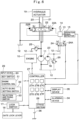
- an explanation will be made of the hydraulic system and the electric control system in the small-sized hydraulic excavator 1 with reference to Fig. 6 .
- the hydraulic pump 11 configures a hydraulic source together with the hydraulic oil tank 12.
- a pilot pump 18 configures a pilot hydraulic source together with the hydraulic oil tank 12. The hydraulic pump 11 and the pilot pump 18 are driven by the engine 10.
- the hydraulic actuator 19 is connected to the hydraulic source composed of the hydraulic pump 11 and the hydraulic oil tank 12 via main lines 20, 21.
- the hydraulic actuator 19 is configured by including the traveling hydraulic motor, the revolving hydraulic motor, the boom cylinder 5G, the offset cylinder 5H, the arm cylinder 5J, and the bucket cylinder 5K.
- the directional control valve 22 of a hydraulic pilot type of a 6-port and a 3-position is provided in the course of the main lines 20, 21, for example, .
- the directional control valve 22 is provided individually in each of the traveling hydraulic motor, the revolving hydraulic motor, the boom cylinder 5G, the offset cylinder 5H, the arm cylinder 5J, and the bucket cylinder 5K, which configure the hydraulic actuator 19.
- the directional control valve 22 has hydraulic pilot parts 22A, 22B.
- the directional control valve 22 When the pilot pressure is not supplied to each of the hydraulic pilot parts 22A, 22B, the directional control valve 22 is held in the neutral position (a) to discharge the pressurized oil delivered from the hydraulic pump 11 to the hydraulic oil tank 12.
- the pilot pressure is supplied to the hydraulic pilot part 22A or the hydraulic pilot part 22B, the directional control valve 22 is switched to the switch position (b) or the switch position (c). Thereby, the pressurized oil from the hydraulic pump 11 is supplied to the hydraulic actuator 19 via the main lines 20, 21 to operate the hydraulic actuator 19.
- the pilot pump 18 and each of the hydraulic pilot parts 22A, 22B of the directional control valve 22 are connected via a pilot line 23.
- the operation lever device 13 is provided in the course of the pilot line 23. Accordingly, the pilot pressure as an operation signal is selectively supplied to the hydraulic pilot parts 22A, 22B of the directional control valve 22 in response to an operation to the operation lever device 13 (the traveling operation lever pedal 13A and working operation lever 13B) .
- the pilot line 23 is provided with a block valve 24 between the pilot pump 18 and the operation lever device 13.
- the block valve 24 is composed of a solenoid valve of a 3-port and a 2-position having a solenoid pilot part 24A, and is switched to a block position (d) where the pilot line 23 is blocked and a communication position (e) where the pilot line 23 is communicated.
- the block valve 24 holds the block position (d) when the gate lock lever 16 is in the lock position. In a case where the operation lever device 13 is operated in this state, the supply of the pilot pressure to each of the hydraulic pilot parts 22A, 22B of the directional control valve 22 is prohibited, and the hydraulic actuator 19 becomes in a non-operating state.
- the block valve 24 is switched to the communication position (e) by supply of the signal from the controller 27 to the solenoid pilot part 24A.
- the pilot pressure is supplied to each of the hydraulic pilot parts 22A, 22B of the directional control valve 22 in response to the operation of the operation lever device 13, and the hydraulic actuator 19 becomes in an operating state.
- a main relief valve 25 is provided in the main line 20 (21) between the hydraulic pump 11 and the directional control valve 22.
- a pilot relief valve 26 is provided in the pilot line 23 between the pilot pump 18 and the block valve 24.
- the main relief valve 25 opens when a delivery pressure from the hydraulic pump 11 exceeds a set pressure to relieve an excessive pressure to the hydraulic oil tank 12-side.
- the pilot relief valve 26 opens when a delivery pressure from the pilot pump 18 exceeds a set pressure to maintain the pilot pressure in the pilot line 23 to be constant. Thereby, the reduced operation pressure in the operation lever device 13 is supplied to the hydraulic pilot parts 22A, 22B as an operation signal.
- controller 27 that controls operations of the engine 10, the block valve 24, the later-described alarming device 34, a display device 35, and the like.
- the controller 27 is mounted on the small-sized hydraulic excavator 1, and is connected to the engine 10, the operation signal detector 15, the lock switch 17, the block valve 24, the later-described input device 29, the alarming device 34, the display device 35, and the like.
- the controller 27 is configured by, for example, a microcomputer and the like, and generates control instructions to the engine 10, the block valve 24, the alarming device 34, the display device 35, and the like to execute various kinds of control functions. Specifically, the controller 27 performs rotational speed control of the engine 10, drive control of the block valve 24, alarming generating control of the alarming device 34, screen switch control of the display device 35, and the like.
- the controller 27 performs auto idling control of switching the rotational speed of the engine 10 to an idling rotational speed.
- the controller 27 performs engine automatic stop control (idling stop control) for automatically stopping the engine 10.
- the controller 27 is configured by including a restart standby time determining section 27A, a horn switch operation determining section 27B, a gate lock lever position determining section 27C, a restart preparation time determining section 27D, an engine restart section 27E, and a power supply stopping section 27F.
- the restart standby time determining section 27A determines an idling stop state.
- the horn switch operation determining section 27B determines whether or not the horn switch 14 is operated.
- the gate lock lever position determining section 27C determines whether the gate lock lever 16 is in the lock position or in the lock release position.
- the restart preparation time determining section 27D determines whether or not a preparation time until the engine 10 restarts has elapsed.
- the engine restart section 27E restarts the engine 10.
- the power supply stopping section 27F stops an electric power supply of a vehicle. An explanation will be later made of the details of the idling stop control and the restart control of the engine 10 after the idling stop control by the controller 27.
- the controller 27 has a storage section (a memory) 28.
- An initial setting related to the idling stop control is stored in the storage section 28.
- the initial setting related to the idling stop function indicates, for example, a setting on whether to make the idling stop function effective or ineffective, and a setting of time (an idling stop setting time) T1 to a point of causing the engine 10 to stop from a point when the gate lock lever 16 becomes in the lock position (the raising position) when the idling stop function is made effective.
- the input device 29 is positioned in the cab 8 to be provided in the right side to the driver's seat 9.
- the input device 29 is provided with a key switch 30, an engine control dial 31, an auto idling setting switch 32, a selection and fixing switch 33 and the like, and is operated by the operator who sits on the driver's seat 9.
- the key switch 30 is operated by using an engine key (not shown) for starting the engine 10.
- the engine control dial 31 sets a target rotational speed of the engine 10 within a predetermined range in accordance with a rotational position of a dial.
- the auto idling setting switch 32 sets whether a later-described auto idling function should be made effective or ineffective.
- the selection and fixing switch 33 is composed of a dial type switch capable of performing a rotational operation and a pressing operation.
- the selection and fixing switch 33 is operated for performing, for example, switch of the later-described display device 35, a setting of an air conditioner, a setting of a radio, a setting of a working mode, and the initial setting related to the later-described idling stop function and the like.
- the alarming device 34 as a horn is provided on the upper revolving structure 3, and generates an alarming sound toward the surroundings of the small-sized hydraulic excavator 1.
- the alarming device 34 generates an alarming sound by an operation of the horn switch 14 to urge workers working around the small-sized hydraulic excavator 1 to take precautions.
- the alarming device 34 is connected to the controller 27, and generates (sounds) alarming sounds by a control signal from the controller 27.
- the display device 35 as a monitor is positioned within the cab 8, and is provided in front of the driver's seat 9.
- the display device 35 is configured by a crystal monitor, for example, and displays a driving situation of the small-sized hydraulic excavator 1 on a screen 35A.
- the display device 35 is connected to the controller 27, and displays a screen in response to an instruction from the controller 27.
- Various pieces of information related to the vehicle body such as a remaining amount of fuel, a water temperature of engine cooling water, a working time, and a vehicle compartment temperature are displayed on the display device 35.
- the display device 35 displays a target rotational speed of the engine 10 in response to an operation of the engine control dial 31.
- the display device 35 displays "effective" and “ineffective” of the auto idling function in response to an operation of the auto idling setting switch 32.
- the display device 35 displays the respective setting contents.
- the operator can perform the initial setting related to the idling stop function by using the selection and fixing switch 33 and the display device 35.
- the display device 35 displays the content of the initial setting. That is, the display device 35 displays the setting on whether to make the idling stop function effective or ineffective, a stop determination time T1, a restart standby time T2 and a restart preparation time T3.
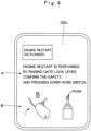
- the display device 35 displays on the screen 35A the effect of waiting for an operation of the restart of the engine 10. In this case, an operation procedure in a case of performing the restart of the engine 10 is displayed on the screen 35A of the display device 35.
- the display device 35 displays on the screen 35A the effect of being in preparation until the engine 10 restarts.
- a battery 36 is an electric power supply of electrical equipment including the engine 10. Specifically, the battery 36 is the electric power supply of electrical equipment for driving (operating) the engine 10, the controller 27, the alarming device 34, the display device 35 and the like.
- the battery 36 adopts a general lead storage battery as a storage device that stores electrical charge, for example.
- the small-sized hydraulic excavator 1 has the configuration as described above, and next, an explanation will be made of the operation with reference to the control processing of the controller 27 shown in Fig. 7 .
- step 1 it is determined whether or not the horn switch 14 is pressed down. That is, for notifying the surroundings the work by the small-sized hydraulic excavator 1 is started, the controller 27 determines whether or not the operator has operated the horn switch 14. In a case where "YES" is determined at step 1, that is, in a case where it is determined that the horn switch 14 is pressed down, the process goes to step 2, wherein the alarming device 34 sounds. On the other hand, in a case where "NO" is determined at step 1, that is, in a case where it is determined that the horn switch 14 is not pressed down, the process goes to step 4.
- step 3 it is determined whether or not the engine 10 is in the engine restart on standby. That is, the controller 27 determines whether or not the engine 10 is in the idling stop state. In this case, since the engine 10 is not in the engine restart on standby, at step 3 "NO" is determined, and the process goes to the next step 4.
- step 4 it is determined whether or not the key switch 30 is in the key start position. That is, the controller 27 determines whether or not the operator has operated the key switch 30 to a start position using an engine key. It should be noted that in a case where "NO" is determined at step 1, that is, even when the horn switch 14 is not operated and the horn does not sound, the process goes to step 4, but it is preferable that, for certainly notifying workers around the small-sized hydraulic excavator 1 of the start of the operation, the horn is caused to sound (at step 2) and then, the process goes to step 4.
- step4 In a case where "YES” is determined at step4, that is in a case where it is determined that the key switch 30 is operated in the key start position, the process goes to step 5. On the other hand, in a case where "NO” is determined at step 4, that is, in a case where it is determined that the key switch 30 is not operated in the key start position, the process returns to step 1.
- step 5 it is determined whether or not the gate lock lever 16 is in the lock position (the raising position). That is, the controller 27 defines as a condition of an engine start a state where the gate lock lever 16 is put to the lock position (the raising position) to make the operation of the operation lever device 13 ineffective, for suppressing an unintended operation of the small-sized hydraulic excavator 1.
- step 5 In a case where "YES” is determined at step 5, that is, in a case where it is determined that the gate lock lever 16 is in the lock position, the process goes to step 6. On the other hand, in a case where "NO” is determined at step 5, that is, in a case where it is determined that the gate lock lever 16 is in the lock release position (the lowering position), the process returns to step 1.
- the engine 10 is started.
- the controller 27 determines that the gate lock lever 16 is switched to the lock release position by the control signal from the lock switch 17.
- the controller 27 outputs the control signal to the solenoid pilot part 24A in the block valve 24. Accordingly, the block valve 24 provided in the pilot line 23 is switched from the block position (d) to the communication position (e), and a pilot pressure in response to the operation of the operation lever device 13 is capable of being supplied to the hydraulic pilot part 22A or the hydraulic pilot part 22B in the directional control valve 22.
- the small-sized hydraulic excavator 1 performs the traveling operation by the lower traveling structure 2, the revolving operation by the upper revolving structure 3, and the excavating operation by the offset front device 5.
- the operator operates the engine control dial 31 of the input device 29, thus, making it possible to set the engine rotational speed as needed.
- the controller 27 performs the auto idling control that lowers the rotational speed of the engine 10. As a result, a wasteful fuel consumption amount can be suppressed, and an exhaust gas, noises and the like can be reduced to improve an environment of the working site.
- an engine automatic stop condition that is, an idling stop condition
- the engine automatic stop control is control to, assuming the small-sized hydraulic excavator 1 to be in the non-working state when the gate lock lever 16 is operated to the lock position, automatically stop the engine 10 when this non-working state lasts for a specified time.
- the engine automatic stop condition is composed of a case where the auto idling setting switch 32 of the input device 29 is turning on (effective), a case where the gate lock lever 16 is in the lock position (the raising position), a case where the engine 10 is not in an overheat state, and a case where particulate matter trapped in a filter in an unillustrated exhaust gas post-treatment device is not during burning off (regeneration). That is, in a case where the start (the drive) of the engine 10 is necessary by the other control, the other control is prioritized and the automatic stop of the engine 10 is not performed.
- step 7 In a case where "YES” is determined at step 7, that is, in a case where it is determined that the engine automatic stop condition is satisfied, the controller 27 starts to measure time t1, and the process goes to step 8. On the other hand, in a case where "NO” is determined at step 7, that is, in a case where it is determined that the engine automatic stop condition is not satisfied, the controller 27 monitors the engine automatic stop condition until it is satisfied.
- the controller 27 determines whether or not the elapse time t1 since the engine automatic stop condition is established is equal to or more than the stop determination time T1 (t1 ⁇ T1) .
- the stop determination time T1 may be set to an optional time within, for example, one minute to ten minutes (preferably within three minutes to five minutes) using the display device 35 and the selection and fixing switch 33.
- step 8 In a case where "YES” is determined at step 8, that is, in a case where it is determined that the time t1 since the engine automatic stop condition is satisfied is equal to or more than the stop determination time T1 (t1 ⁇ T1), the process goes to step 9. On the other hand, In a case where "NO” is determined at step 8, that is, in a case where it is determined that the time t1 since the engine automatic stop condition is satisfied does not reach the stop determination time T1 (t1 ⁇ T1) yet, the process returns to step 7, wherein the controller 27 monitors whether or not the engine automatic stop condition is satisfied, and measures the time t1.
- the engine 10 is stopped. That is, the controller 27 causes the engine 10 to be in the idling stop state of stopping the engine 10 in a state where the vehicle power supply is turning on.
- the controller 27 resets the time t1 since the engine automatic stop condition is satisfied, and starts the measurement of time t2 since the engine 10 is stopped.
- step 11 it is determined whether or not the horn switch 14 is pressed down. That is, the controller 27, for notifying workers around of restarting the work by the small-sized hydraulic excavator 1, determines whether or not the operator has operated the horn switch 14. In a case where "YES” is determined at step 11, that is, in a case where it is determined that the horn switch 14 is pressed down, the process goes to step 2, wherein the horn sounds from the alarming device 34, and the process goes to step 3. At step 3 "YES" is determined because of the engine restart on standby, and the process goes to step 12. On the other hand, in a case where "NO" is determined at step 11, that is, in a case where it is determined that the horn switch 14 is not pressed down, the process goes to step 16.
- step 12 it is determined whether or not the gate lock lever 16 is in the lock position (the raising position). That is, the controller 27 defines as a condition of an engine restart a state where the gate lock lever 16 is put to the lock position (the raising position) to make the operation of the operation lever device 13 ineffective.
- the process goes to step 13.
- "NO" is determined at step 12 that is, in a case where it is determined that the gate lock lever 16 is in the lock release position (the lowering position)
- step 13 "restart in preparation” is displayed on the screen 35A of the display device 35.
- the controller 27 starts the measurement of time t3 corresponding to a preparation time until the engine 10 restarts (restart preparation time T3) . That is, the controller 27 switches the display of "restart on standby” displayed on the screen 35A of the display device 35 to the display of "restart in preparation”, and starts the measurement of the time t3 on a condition that the horn switch 14 is pressed down in the restart on standby (in the idling stop state) and the gate lock lever 16 is in the lock position. The controller 27 maintains the measurement of the time t2 in the restart on standby.
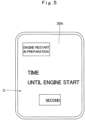
- Fig. 5 shows an example of the display of "restart in preparation”.
- the effect of waiting for the restart of the engine 10 is notified by displaying "engine restart in preparation" on the upper side of the screen 35A of the display device 35.
- an image C on how many minutes are left until the engine 10 restarts is displayed on the lower side of "engine restart in preparation”.
- the controller 27 determines whether or not the elapse time t3 since the engine restart condition is established is equal to or more than the restart preparation time T3 (t3 ⁇ T3).
- the restart preparation time T3 is set as a retreat time in which workers can retreat in a position capable of preventing contact with the small-sized hydraulic excavator 1 after the workers and the like around the small-sized hydraulic excavator 1 recognize an alarming sound sounding from the alarming device 34.
- the restart preparation time T3 is set as a confirmation time for certainly confirming that the operator restarts the work of the small-sized hydraulic excavator 1.
- the restart preparation time T3 may be set to an optional time within, for example, one second to ten seconds (preferably within two seconds to three seconds) using the display device 35 and the selection and fixing switch 33 as needed.
- step 14 In a case where "YES" is determined at step 14, that is, in a case where it is determined that the time t3 since the engine restart condition is satisfied is equal to or more than the restart preparation time T3 (t3 ⁇ T3), the process goes to step 6, wherein the engine 10 is restarted.
- the controller 27 resets time t2 in the restart on standby and time t3 since the engine restart condition is satisfied.
- the controller 27 deletes the display of "restart in preparation" displayed on the screen 35A of the display device 35 to be switched to a predetermined display screen.
- the gate lock lever 16 is operated from the lock position (the raising position) to the lock release position (the lowering position), and then, the operation lever device 13 is operated. Thereby, the traveling operation by the lower traveling structure 2, the revolving operation by the upper revolving structure 3, the excavating operation by the offset front device 5 and the like can be performed.
- step 14 in a case where "NO" is determined at step 14, that is, in a case where it is determined that the time t3 since the engine restart condition is satisfied does not reach the restart preparation time T3 (t3 ⁇ T3), the process goes to step 15.
- step 15 it is determined whether or not the gate lock lever 16 is in the lock position. That is, the controller 27 monitors whether or not a state where the gate lock lever 16 is in the lock position is maintained in the restart in preparation (t3 ⁇ T3) .
- step 15 In a case where "YES” is determined at step 15, that is, in a case where it is determined that the state where the gate lock lever 16 is in the lock position is maintained, the process returns to step 14, wherein the measurement of the time t3 after the engine restart condition is satisfied continues.
- step 16 In a case where "NO” is determined at step 15, that is, in a case where it is determined that the gate lock lever 16 is operated in the lock release position in the restart in preparation of the engine 10, the process goes to step 16. In this case, the time t3 since the engine restart condition is satisfied is reset.
- the controller 27 determines whether or not the elapse time t2 since the engine restart on standby (the idling stop state) is established is equal to or more than the restart standby time T2 (t2 ⁇ T2) .
- the restart standby time T2 may be set to an optional time within, for example, one minute to twenty minutes (preferably within five minutes to ten minutes) using the display device 35 and the selection and fixing switch 33 as needed.
- step 16 In a case where "YES” is determined at step 16, that is, in a case where it is determined that the time t2 since the engine restart on standby is established is equal to or more than the restart standby time T2 (t2 ⁇ T2), the process goes to step 17. On the other hand, in a case where "NO” is determined at step 16, that is, in a case where it is determined that the time t2 since the engine restart on standby is established does not reach the restart standby time T2 (t2 ⁇ T2) yet, the process returns to step 10, wherein the controller 27 is monitored whether or not the engine restart condition is satisfied.
- the vehicle power supply is stopped (turns off) . That is, the controller 27 stops the electric power supply of the vehicle for suppressing consumption of power when the time t2 (the idling stop state) since the engine restart on standby is established lasts for a long period of time.
- the controller 27 resets the time t2 since the engine restart on standby is established.
- the controller 27 deletes the display of "restart on standby" displayed on the screen 35A of the display device 35 to be switched to a predetermined display screen and the deletion of the image. It should be noted that, for starting the work of the small-sized hydraulic excavator 1 after the power supply stop, the start of the engine 10 can be performed by operating the key switch 30 from the off position to the start position using the engine key.
- step 11 configures the horn switch operation determining section 27B in the present invention.
- step 12 and step 15 configure the gate lock lever position determining section 27C in the present invention.
- step 14 configures the restart preparation time determining section 27D in the present invention.
- Step 6 via step 14 configures the engine restart section 27E in the present invention.
- Step 16 configures the restart standby time determining section 27A in the present invention.
- Step 17 configures the power supply stopping section 27F in the present invention.
- the present embodiment is configured such that when the gate lock lever 16 is in the lock position during the idling stopping of the engine 10 and the existing horn switch 14 to be used at the regular working is operated, it is possible to restart the engine 10. Thereby, the restart of the engine 10 can be easily performed, and since the alarming sound is generated from the alarming device 34 before the engine restart, it is possible to certainly notify the start of the operation.
- the controller 27 determines whether or not the elapse time t3 since the horn switch 14 is operated at the idling stopping of the engine 10 is equal to or more than the restart preparation time T3 which is set in advance, and in a case where the restart preparation time T3 has elapsed, the engine 10 is restarted. Thereby, since the time from a point of the sounding of the alarming device 34 to a point of the restart of the engine 10 can have allowance, the workers or the like can retreat from the surroundings of the small-sized hydraulic excavator 1, and the operator can confirm the surroundings of the small-sized hydraulic excavator 1 sufficiently.
- the controller 27 causes the display device 35 to display the effect of waiting for the operation of the restart of the engine 10 and the operation procedure in a case of performing the restart of the engine 10. Thereby, the operator can confirm the state of the small-sized hydraulic excavator 1 and the procedure at the time of performing the restart of the work (the restart of the engine 10) of the small-sized hydraulic excavator 1 by the display device 35.
- the controller 27 causes the display device 35 to display the effect of making the preparation until the engine 10 restarts. Therefore, the operator can recognize the time until being capable of restarting the work.
- the driver's seat 9 is provided with the operation lever device 13 that outputs the operation signal for operating the hydraulic actuator 19, and the horn switch 14 is provided in the tip end of the lever 13B1 of the operation lever device 13. Therefore, since the operator restarts the engine 10 in a state of sitting on the driver's seat 9 to take a working posture, it is easier for the operator to confirm the situation of the surroundings of the small-sized hydraulic excavator 1.
- the aforementioned embodiment is explained by taking a case where, at the time of first starting the engine 10, the start of the engine 10 is made possible even without operating the horn switch 14 ("NO" at step 1), as an example.
- the present invention is not limited thereto, but, may be configured such that, for example, also when the engine 10 is first started, the engine 10 may be absolutely not started without operating the horn switch 14.
- the aforementioned embodiment is explained by taking a case where the stop determination time T1, the restart standby time T2 and the restart preparation time T3 can be respectively set as needed by the display device 35 and the selection and fixing switch 33, as an example.
- the present invention is not limited thereto, but, for example, the stop determination time T1, the restart standby time T2 and the restart preparation time T3 may be in advance set (stored) in the storage section 28 in the controller 27.
- the aforementioned embodiment is explained by taking a case of displaying in numbers how many seconds are left by the time (the restart preparation time) of starting the engine 10, as an example.
- the present invention is not limited thereto, but it may be displayed using a graph and the like, for example. This is similarly applied to the restart standby time.
- the aforementioned embodiment is explained by taking a case where the alarming device 34 generates the alarming sound by the control signal from the controller 27 in the processing at step 2, as an example.
- the present invention is not limited thereto, but may be configured such that, for example, the alarming device 34 is connected directly to the battery 36, and the alarming device 34 is subjected to power supply from the battery 36 by an operation of the horn switch 14, causing the alarming device 34 to generate the alarming sound.
- the aforementioned embodiment is explained by taking a case of using the single directional control valve 22 as an representative example of the directional control valves that operate the hydraulic actuator 19 composed of the traveling hydraulic motor, the revolving hydraulic motor, the boom cylinder 5G, the offset cylinder 5H, the arm cylinder 5J, the bucket cylinder 5K, and the like in Fig. 6 .
- the directional control valves that operate the hydraulic actuator 19 composed of the traveling hydraulic motor, the revolving hydraulic motor, the boom cylinder 5G, the offset cylinder 5H, the arm cylinder 5J, the bucket cylinder 5K, and the like are configured as a control valve block or multiple control valve.
- the aforementioned embodiment is explained by taking a case where the vehicle body is configured by the lower traveling structure 2, and the upper revolving structure 3 supported on the lower traveling structure 2 to be capable of revolving thereto, as an example.
- the present invention is not limited to the vehicle body composed of the lower traveling structure 2 and the upper revolving structure 3, and may be applied to a single automotive vehicle body without a revolving structure, for example, as a wheel loader, a road roller or the like.
- the aforementioned embodiment is explained by taking a case of the small-sized hydraulic excavator 1 of a cab specification as an example.
- the present invention is not limited thereto, but may be applied to a small-sized hydraulic excavator of a canopy specification, for example.
- the present invention is not limited to the small-sized hydraulic excavator 1, but may be applied to other construction machines such as middle-sized or large-sized hydraulic excavators, mobile cranes or the like.
Landscapes
- Engineering & Computer Science (AREA)
- General Engineering & Computer Science (AREA)
- Mining & Mineral Resources (AREA)
- Civil Engineering (AREA)
- Structural Engineering (AREA)
- Mechanical Engineering (AREA)
- Combustion & Propulsion (AREA)
- Chemical & Material Sciences (AREA)
- Physics & Mathematics (AREA)
- Acoustics & Sound (AREA)
- Operation Control Of Excavators (AREA)
- Component Parts Of Construction Machinery (AREA)
- Control Of Vehicle Engines Or Engines For Specific Uses (AREA)
Description
- The present invention relates to a construction machine that can easily restart an engine automatically stopped when a work is not performed (at the non-working).
- In general, a hydraulic excavator that is a representative example of a construction machine is configured by an automotive lower traveling structure, an upper revolving structure mounted on the lower traveling structure to be capable of revolving thereon, and a working mechanism that is provided on a front side of the upper revolving structure. An engine, a hydraulic pump, a control valve, and the like are mounted on the upper revolving structure. When an operator operates an operation lever, pressurized oil delivered from the hydraulic pump is supplied via a control valve to various kinds of hydraulic actuators. Thereby, the hydraulic excavator revolves the upper revolving structure and performs an excavating work of earth and sand by using the working mechanism.
- A gate lock lever is provided in an entrance of a driver's seat in the hydraulic excavator for a switching operation between a lock position and a lock release position. When the gate lock lever is switched to the lock release position, a pilot signal is outputted to the control valve in response to an operation of the operation lever. Meanwhile, when the gate lock lever is switched to the lock position, output of the pilot signal to the control valve is prohibited.
At the non-working when the hydraulic excavator is not working, as the engine continues to be in an idling state, fuel is wastefully consumed and an environment of a working site deteriorates due to exhaust gases, noises or the like. Therefore, in a case where a specified time has elapsed since the gate lock lever becomes in the lock position, the engine is automatically stopped (Patent Document 1). - Patent Document 1:
Japanese Patent Laid-Open No. 2000-96627 A - However, in the hydraulic excavator according to
Patent Document 1, the engine can be restarted by a reoperation of the gate lock lever. In this case, since an operator has to operate a horn switch to sound the horn before re-operating the gate lock lever, the operator possibly feels troublesome or forgets the operation of the horn switch. -
JP 2003307142 A claim 1, rendering an automatic stop of the engine under certain conditions. -
US 2006/0179830 A1 discloses a control device for a construction machine configured to use a horn switch as a restart switch. - It is the object of the present invention to provide a construction machine that can easily perform restart of an engine and certainly notify workers around of start of an operation.
- This object is accomplished by the features of
claim 1. A construction machine includes the features ofclaim 1. It includes an engine that is mounted on a vehicle body and serves as a prime mover; a hydraulic pump that is driven by the engine and delivers pressurized oil; a hydraulic actuator driven by the pressurized oil delivered from the hydraulic pump; a gate lock lever that is provided in an entrance of a driver's seat of the vehicle body and is switched to a lock position prohibiting a drive of the hydraulic actuator and a lock release position allowing the drive of the hydraulic actuator; a controller configured to have an idling stop function of automatically stopping the engine when a state where the gate lock lever is in the lock position lasts for a specified time; and a horn switch to be operated at the time of generating sounds to the surroundings of the vehicle body from a horn. - In a case where an elapse time after the engine is automatically stopped by the idling stop function does not yet reach a preset restart standby time, the controller is configured to perform control of restarting the engine in a state where the horn switch is operated and the gate lock lever is in the lock position, and in a case where the elapse time after the engine is automatically stopped by the idling stop function has reached the restart standby time, the controller is configured to perform control of stopping a power supply of the vehicle body.
Claim 1 recites further features. - According to the present invention, the restart of the engine can be easily performed and the start of the operation can be securely notified to workers around.
-
-
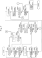
Fig. 1 is a perspective view showing a small-sized hydraulic excavator of an extremely small revolving type that is applied to an embodiment of the present invention. -
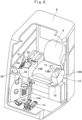
Fig. 2 is a partial broken external perspective view showing an inner part of a cab. -
Fig. 3 is a perspective view showing the inner part of the cab from behind. -
Fig. 4 is a front view showing a state where engine restart on standby and an operation procedure in a case of restarting an engine are displayed on a screen of a display device. -
Fig. 5 is a front view showing a state where engine restart in preparation is displayed on the screen of the display device. -
Fig. 6 is a system configuration diagram showing a hydraulic system including a hydraulic pump and an electric control system including a controller. -
Fig. 7 is a flow chart showing control processing when the controller performs start, automatic stop and restart of the engine. - Hereinafter, an explanation will be in detail made of an embodiment of a construction machine according to the present invention by taking a small-sized hydraulic excavator of an extremely small revolving type as an example with reference to
Fig. 1 to Fig. 7 . - In
Fig. 1 , a small-sizedhydraulic excavator 1 of an extremely small revolving type is used for an excavating work in a narrow site, such as a side ditch digging work at the side of the road in an urban area. A machinery weight thereof is set to approximately 0.8 to 4 tons to be capable of being transported by a general truck. The small-sizedhydraulic excavator 1 is provided with a vehicle body configured by an automotivelower traveling structure 2 and an upper revolvingstructure 3 supported on thelower traveling structure 2 to be capable of revolving thereon. Ablade 4 is provided on the front side of thelower traveling structure 2. An offsetfront device 5 is provided on the front side of the upper revolvingstructure 3 to be capable of tilting up and down. - The
offset front device 5 is configured by alower boom 5A provided on the front side of a revolvingframe 6 of the upper revolvingstructure 3 to be capable of tilting up and down thereto, anupper boom 5B mounted in a front end side of thelower boom 5A to be capable of swinging in a left-right direction, anarm support structure 5C mounted in a front end side of theupper boom 5B to be capable of swinging in the left-right direction, anarm 5D mounted in a front end side of thearm support structure 5C to be rotatable in an upper-lower direction, abucket 5E mounted in a front end side of thearm 5D to be rotatable in the upper-lower direction, alink 5F for connection between thelower boom 5A and thearm support structure 5C, aboom cylinder 5G, anoffset cylinder 5H, anarm cylinder 5J and abucket cylinder 5K as hydraulic actuators for operating the above components. - The offset
front device 5 moves thearm 5D in the left-right direction in parallel to thelower boom 5A with extension or contraction of theoffset cylinder 5H. In this state, thelower boom 5A is tilted up or down while rotating thearm 5D and thebucket 5E, thus, making it possible to perform an excavating work of a side ditch and the like. - The
offset front device 5 tilts up the front end side of thelower boom 5A to the most backward side and folds thearm 5D to thelower boom 5A-side, thereby, making it possible to take an extremely small revolving posture. In a state where the offsetfront device 5 is put in the extremely small revolving posture, when the upper revolvingstructure 3 is revolved, theupper revolving structure 3 and the offsetfront device 5 can fully revolve within a width dimension (a vehicle width dimension) of thelower traveling structure 2 in the left-right direction and within a length dimension of thelower traveling structure 2 in the front-rear direction. - The revolving
frame 6 serves as a base of the upper revolvingstructure 3, and configures a strong support structure. The revolvingframe 6 is mounted on thelower traveling structure 2 to be capable of revolving thereon via revolving wheels. Acounterweight 7 is provided in the rear end part of the revolvingframe 6 to act as a weight balance to the offsetfront device 5. - A
cab 8 is provided in the left front side of the revolvingframe 6. A driver'sseat 9 on which an operator sits is provided in thecab 8. Thecab 8 is formed in a boxy shape surrounding the periphery of the driver'sseat 9. An openable andclosable door 8A is provided in the left side surface of thecab 8, and the operator gets on or off thecab 8 by opening thedoor 8A. A later-describedoperation lever device 13, agate lock lever 16, aninput device 29 and the like are located in the periphery of the driver'sseat 9. - The
engine 10 is located closer to the front side than thecounterweight 7 and is provided in back of the revolvingframe 6. Theengine 10 is mounted on the revolvingframe 6 in a transverse-mounted state where a crank shaft (not shown) extends in the left-right direction. Theengine 10 is a diesel engine (an internal combustion engine), for example, and configures a drive source that drives and rotates the hydraulic pump 11. The hydraulic pump 11 is connected mechanically to the output side of the engine 10 (refer toFig. 6 ). - The hydraulic pump 11 is driven and rotated by the
engine 10, and configures a hydraulic source together with ahydraulic oil tank 12 provided in the right side of thecab 8 across the offsetfront device 5. The hydraulic pump 11 is configured by, for example, a variable displacement type of a swash-plate, a bent-axis or a radial piston hydraulic pump or the like, and suctions hydraulic oil from thehydraulic oil tank 12 and delivers this hydraulic oil as high-pressure pressurized oil. The pressurized oil delivered from the hydraulic pump 11 is supplied to ahydraulic actuator 19 via a later-describeddirectional control valve 22. - The
operation lever device 13 is configured by including a travelingoperation lever pedal 13A located in front of the driver'sseat 9, and left and right working operation levers 13B located in both of the left and right sides of the driver'sseat 9. Theoperation lever device 13 outputs an operation signal for operating thehydraulic actuator 19. Specifically, the travelingoperation lever pedal 13A is operated at the time of controlling the operation of the traveling hydraulic motor (not shown) for driving drive wheels (not shown) of thelower traveling structure 2. - On the other hand, the left and right working operation levers 13B are operated at the time of controlling operations of a revolving hydraulic motor (not shown) to be driven at the time of revolving the upper revolving
structure 3 and therespective cylinders front device 5. Ahorn switch 14 is provided in a tip end of a lever 13B1 configuring the workingoperation lever 13B provided in the left side. Thehorn switch 14 is pressed down at the time of generating an alarm sound from a later-describedalarming device 34 toward the surroundings of the small-sizedhydraulic excavator 1 regardless of before start or after start of theengine 10. It should be noted that thehorn switch 14 is not limited to the left workingoperation lever 13B, but may be provided in each of the right working operation levers 13B and the travelingoperation lever pedal 13A. - An
operation signal detector 15 is provided in the operation lever device 13 (refer toFig. 6 ) . Theoperation signal detector 15 detects whether or not operations to theoperation lever device 13 and thehorn switch 14 are performed. When theoperation lever device 13 and thehorn switch 14 are operated, the detection signals are outputted to a later-describedcontroller 27. Thecontroller 27 determines whether or not the operations to theoperation lever device 13 and thehorn switch 14 are performed based upon the signal from theoperation signal detector 15. - The
gate lock lever 16 is positioned under the left workingoperation lever 13B, and is provided in thedoor 8A-side (an entrance/exit side) of thecab 8. Thegate lock lever 16 is operated to a lock position (a raising position) of opening the entrance of thecab 8, and a lock release position (a lowering position) of blocking the entrance of thecab 8 when the operator gets on or gets off thecab 8. Thegate lock lever 16 is switched to a lock position of prohibiting a drive of thehydraulic actuator 19 and a lock release position of allowing the drive of thehydraulic actuator 19. - That is, when the
gate lock lever 16 is set to the lock position, supply of a pilot pressure to the later-describeddirectional control valve 22 is prohibited. Thereby, thehydraulic actuator 19 does not operate even when theoperation lever device 13 is operated. On the other hand, when thegate lock lever 16 is set to the lock release position, the supply of the pilot pressure to thedirectional control valve 22 is allowed. Thereby, thehydraulic actuator 19 operates based upon the operation of theoperation lever device 13. - A
lock switch 17 is provided in the gate lock lever 16 (refer toFig. 6 ). Thelock switch 17 is configured by a mechanical switch in association with the operation of thegate lock lever 16, for example. Thelock switch 17 detects that thegate lock lever 16 is set to the lock position, and outputs a detection signal to thecontroller 27. Thecontroller 27 determines whether thegate lock lever 16 is in the lock position or in the lock release position, based upon the signal from thelock switch 17. - Here, a hydraulic system that controls the operation of the
hydraulic actuator 19 and an electric control system that controls the operation of theengine 10 and the like are mounted on the small-sizedhydraulic excavator 1. Hereinafter, an explanation will be made of the hydraulic system and the electric control system in the small-sizedhydraulic excavator 1 with reference toFig. 6 . - The hydraulic pump 11 configures a hydraulic source together with the
hydraulic oil tank 12. Apilot pump 18 configures a pilot hydraulic source together with thehydraulic oil tank 12. The hydraulic pump 11 and thepilot pump 18 are driven by theengine 10. - The
hydraulic actuator 19 is connected to the hydraulic source composed of the hydraulic pump 11 and thehydraulic oil tank 12 viamain lines hydraulic actuator 19 is configured by including the traveling hydraulic motor, the revolving hydraulic motor, theboom cylinder 5G, the offsetcylinder 5H, thearm cylinder 5J, and thebucket cylinder 5K. - The
directional control valve 22 of a hydraulic pilot type of a 6-port and a 3-position is provided in the course of themain lines directional control valve 22 is provided individually in each of the traveling hydraulic motor, the revolving hydraulic motor, theboom cylinder 5G, the offsetcylinder 5H, thearm cylinder 5J, and thebucket cylinder 5K, which configure thehydraulic actuator 19. - The
directional control valve 22 hashydraulic pilot parts hydraulic pilot parts directional control valve 22 is held in the neutral position (a) to discharge the pressurized oil delivered from the hydraulic pump 11 to thehydraulic oil tank 12. When the pilot pressure is supplied to thehydraulic pilot part 22A or thehydraulic pilot part 22B, thedirectional control valve 22 is switched to the switch position (b) or the switch position (c). Thereby, the pressurized oil from the hydraulic pump 11 is supplied to thehydraulic actuator 19 via themain lines hydraulic actuator 19. - The
pilot pump 18 and each of thehydraulic pilot parts directional control valve 22 are connected via apilot line 23. Theoperation lever device 13 is provided in the course of thepilot line 23. Accordingly, the pilot pressure as an operation signal is selectively supplied to thehydraulic pilot parts directional control valve 22 in response to an operation to the operation lever device 13 (the travelingoperation lever pedal 13A and workingoperation lever 13B) . - The
pilot line 23 is provided with ablock valve 24 between thepilot pump 18 and theoperation lever device 13. Theblock valve 24 is composed of a solenoid valve of a 3-port and a 2-position having asolenoid pilot part 24A, and is switched to a block position (d) where thepilot line 23 is blocked and a communication position (e) where thepilot line 23 is communicated. - The
block valve 24 holds the block position (d) when thegate lock lever 16 is in the lock position. In a case where theoperation lever device 13 is operated in this state, the supply of the pilot pressure to each of thehydraulic pilot parts directional control valve 22 is prohibited, and thehydraulic actuator 19 becomes in a non-operating state. - On the other hand, when the
gate lock lever 16 is switched to the lock release position, theblock valve 24 is switched to the communication position (e) by supply of the signal from thecontroller 27 to thesolenoid pilot part 24A. In this case, the pilot pressure is supplied to each of thehydraulic pilot parts directional control valve 22 in response to the operation of theoperation lever device 13, and thehydraulic actuator 19 becomes in an operating state. - A
main relief valve 25 is provided in the main line 20 (21) between the hydraulic pump 11 and thedirectional control valve 22. Apilot relief valve 26 is provided in thepilot line 23 between thepilot pump 18 and theblock valve 24. Themain relief valve 25 opens when a delivery pressure from the hydraulic pump 11 exceeds a set pressure to relieve an excessive pressure to the hydraulic oil tank 12-side. - On the other hand, the
pilot relief valve 26 opens when a delivery pressure from thepilot pump 18 exceeds a set pressure to maintain the pilot pressure in thepilot line 23 to be constant. Thereby, the reduced operation pressure in theoperation lever device 13 is supplied to thehydraulic pilot parts - Next, an explanation will be made of the
controller 27 that controls operations of theengine 10, theblock valve 24, the later-describedalarming device 34, adisplay device 35, and the like. - The
controller 27 is mounted on the small-sizedhydraulic excavator 1, and is connected to theengine 10, theoperation signal detector 15, thelock switch 17, theblock valve 24, the later-describedinput device 29, thealarming device 34, thedisplay device 35, and the like. Thecontroller 27 is configured by, for example, a microcomputer and the like, and generates control instructions to theengine 10, theblock valve 24, thealarming device 34, thedisplay device 35, and the like to execute various kinds of control functions. Specifically, thecontroller 27 performs rotational speed control of theengine 10, drive control of theblock valve 24, alarming generating control of thealarming device 34, screen switch control of thedisplay device 35, and the like. - In addition, when the
operation lever device 13 is continuously not operated for a constant time, thecontroller 27 performs auto idling control of switching the rotational speed of theengine 10 to an idling rotational speed. When thegate lock lever 16 continuously holds the lock position (the raising position) for a constant time, thecontroller 27 performs engine automatic stop control (idling stop control) for automatically stopping theengine 10. - Therefore, the
controller 27 is configured by including a restart standbytime determining section 27A, a horn switchoperation determining section 27B, a gate lock leverposition determining section 27C, a restart preparationtime determining section 27D, anengine restart section 27E, and a powersupply stopping section 27F. The restart standbytime determining section 27A determines an idling stop state. The horn switchoperation determining section 27B determines whether or not thehorn switch 14 is operated. The gate lock leverposition determining section 27C determines whether thegate lock lever 16 is in the lock position or in the lock release position. The restart preparationtime determining section 27D determines whether or not a preparation time until theengine 10 restarts has elapsed. Theengine restart section 27E restarts theengine 10. The powersupply stopping section 27F stops an electric power supply of a vehicle. An explanation will be later made of the details of the idling stop control and the restart control of theengine 10 after the idling stop control by thecontroller 27. - The
controller 27 has a storage section (a memory) 28. An initial setting related to the idling stop control is stored in thestorage section 28. In this case, the initial setting related to the idling stop function indicates, for example, a setting on whether to make the idling stop function effective or ineffective, and a setting of time (an idling stop setting time) T1 to a point of causing theengine 10 to stop from a point when thegate lock lever 16 becomes in the lock position (the raising position) when the idling stop function is made effective. - The
input device 29 is positioned in thecab 8 to be provided in the right side to the driver'sseat 9. Theinput device 29 is provided with akey switch 30, anengine control dial 31, an autoidling setting switch 32, a selection and fixingswitch 33 and the like, and is operated by the operator who sits on the driver'sseat 9. - The
key switch 30 is operated by using an engine key (not shown) for starting theengine 10. Theengine control dial 31 sets a target rotational speed of theengine 10 within a predetermined range in accordance with a rotational position of a dial. The autoidling setting switch 32 sets whether a later-described auto idling function should be made effective or ineffective. - The selection and fixing
switch 33 is composed of a dial type switch capable of performing a rotational operation and a pressing operation. The selection and fixingswitch 33 is operated for performing, for example, switch of the later-describeddisplay device 35, a setting of an air conditioner, a setting of a radio, a setting of a working mode, and the initial setting related to the later-described idling stop function and the like. - The
alarming device 34 as a horn is provided on the upper revolvingstructure 3, and generates an alarming sound toward the surroundings of the small-sizedhydraulic excavator 1. Thealarming device 34 generates an alarming sound by an operation of thehorn switch 14 to urge workers working around the small-sizedhydraulic excavator 1 to take precautions. Thealarming device 34 is connected to thecontroller 27, and generates (sounds) alarming sounds by a control signal from thecontroller 27. - The
display device 35 as a monitor is positioned within thecab 8, and is provided in front of the driver'sseat 9. Thedisplay device 35 is configured by a crystal monitor, for example, and displays a driving situation of the small-sizedhydraulic excavator 1 on ascreen 35A. Thedisplay device 35 is connected to thecontroller 27, and displays a screen in response to an instruction from thecontroller 27. Various pieces of information related to the vehicle body such as a remaining amount of fuel, a water temperature of engine cooling water, a working time, and a vehicle compartment temperature are displayed on thedisplay device 35. - The
display device 35 displays a target rotational speed of theengine 10 in response to an operation of theengine control dial 31. Thedisplay device 35 displays "effective" and "ineffective" of the auto idling function in response to an operation of the autoidling setting switch 32. When the air conditioner, the radio and the working mode are set using the selection and fixingswitch 33, thedisplay device 35 displays the respective setting contents. - The operator can perform the initial setting related to the idling stop function by using the selection and fixing
switch 33 and thedisplay device 35. When the initial setting related to the idling stop function is performed by using the selection and fixingswitch 33, thedisplay device 35 displays the content of the initial setting. That is, thedisplay device 35 displays the setting on whether to make the idling stop function effective or ineffective, a stop determination time T1, a restart standby time T2 and a restart preparation time T3. - As shown in
Fig.4 , when it is determined that the restart standby time does not elapse by the restart standbytime determining section 27A of thecontroller 27, thedisplay device 35 displays on thescreen 35A the effect of waiting for an operation of the restart of theengine 10. In this case, an operation procedure in a case of performing the restart of theengine 10 is displayed on thescreen 35A of thedisplay device 35. As shown inFig.5 , when it is determined that the restart preparation time does not elapse by the restart preparationtime determining section 27D of thecontroller 27, thedisplay device 35 displays on thescreen 35A the effect of being in preparation until theengine 10 restarts. - A
battery 36 is an electric power supply of electrical equipment including theengine 10. Specifically, thebattery 36 is the electric power supply of electrical equipment for driving (operating) theengine 10, thecontroller 27, thealarming device 34, thedisplay device 35 and the like. Thebattery 36 adopts a general lead storage battery as a storage device that stores electrical charge, for example. - The small-sized
hydraulic excavator 1 according to the present embodiment has the configuration as described above, and next, an explanation will be made of the operation with reference to the control processing of thecontroller 27 shown inFig. 7 . - First, an explanation will be made of a case where the operator gets in the
cab 8 and sits on the driver'sseat 9, and then, operates the small-sizedhydraulic excavator 1 under power stopping. - At
step 1, it is determined whether or not thehorn switch 14 is pressed down. That is, for notifying the surroundings the work by the small-sizedhydraulic excavator 1 is started, thecontroller 27 determines whether or not the operator has operated thehorn switch 14. In a case where "YES" is determined atstep 1, that is, in a case where it is determined that thehorn switch 14 is pressed down, the process goes to step 2, wherein thealarming device 34 sounds. On the other hand, in a case where "NO" is determined atstep 1, that is, in a case where it is determined that thehorn switch 14 is not pressed down, the process goes to step 4. - At
step 3, it is determined whether or not theengine 10 is in the engine restart on standby. That is, thecontroller 27 determines whether or not theengine 10 is in the idling stop state. In this case, since theengine 10 is not in the engine restart on standby, atstep 3 "NO" is determined, and the process goes to thenext step 4. - At
step 4, it is determined whether or not thekey switch 30 is in the key start position. That is, thecontroller 27 determines whether or not the operator has operated thekey switch 30 to a start position using an engine key. It should be noted that in a case where "NO" is determined atstep 1, that is, even when thehorn switch 14 is not operated and the horn does not sound, the process goes to step 4, but it is preferable that, for certainly notifying workers around the small-sizedhydraulic excavator 1 of the start of the operation, the horn is caused to sound (at step 2) and then, the process goes to step 4. - In a case where "YES" is determined at step4, that is in a case where it is determined that the
key switch 30 is operated in the key start position, the process goes to step 5. On the other hand, in a case where "NO" is determined atstep 4, that is, in a case where it is determined that thekey switch 30 is not operated in the key start position, the process returns to step 1. - At
step 5, it is determined whether or not thegate lock lever 16 is in the lock position (the raising position). That is, thecontroller 27 defines as a condition of an engine start a state where thegate lock lever 16 is put to the lock position (the raising position) to make the operation of theoperation lever device 13 ineffective, for suppressing an unintended operation of the small-sizedhydraulic excavator 1. - In a case where "YES" is determined at
step 5, that is, in a case where it is determined that thegate lock lever 16 is in the lock position, the process goes to step 6. On the other hand, in a case where "NO" is determined atstep 5, that is, in a case where it is determined that thegate lock lever 16 is in the lock release position (the lowering position), the process returns to step 1. - At
step 6, theengine 10 is started. In a case where thegate lock lever 16 is operated from the lock position to the lock release position after the start of theengine 10, thecontroller 27 determines that thegate lock lever 16 is switched to the lock release position by the control signal from thelock switch 17. Thecontroller 27 outputs the control signal to thesolenoid pilot part 24A in theblock valve 24. Accordingly, theblock valve 24 provided in thepilot line 23 is switched from the block position (d) to the communication position (e), and a pilot pressure in response to the operation of theoperation lever device 13 is capable of being supplied to thehydraulic pilot part 22A or thehydraulic pilot part 22B in thedirectional control valve 22. - As a result, in the small-sized
hydraulic excavator 1, the pressurized oil from the hydraulic pump 11 is delivered to thehydraulic actuator 19 via thedirectional control valve 22 in response to the operation to theoperation lever device 13. Therefore, the small-sizedhydraulic excavator 1 performs the traveling operation by thelower traveling structure 2, the revolving operation by the upper revolvingstructure 3, and the excavating operation by the offsetfront device 5. In this case, the operator operates theengine control dial 31 of theinput device 29, thus, making it possible to set the engine rotational speed as needed. - In a case where the operation to the
operation lever device 13 or theengine control dial 31 is continuously not performed for a specified time (an auto idling setting time) or more, since a signal from theoperation signal detector 15 or theengine control dial 31 is not input to thecontroller 27, thecontroller 27 performs the auto idling control that lowers the rotational speed of theengine 10. As a result, a wasteful fuel consumption amount can be suppressed, and an exhaust gas, noises and the like can be reduced to improve an environment of the working site. - Next, an explanation will be made of a case where the working is interrupted due to the standby or the like, and the
engine 10 is automatically stopped and a case where theengine 10 is restarted. - In this case, it is determined at
step 7 whether or not an engine automatic stop condition (that is, an idling stop condition) is satisfied. The engine automatic stop control is control to, assuming the small-sizedhydraulic excavator 1 to be in the non-working state when thegate lock lever 16 is operated to the lock position, automatically stop theengine 10 when this non-working state lasts for a specified time. - The engine automatic stop condition is composed of a case where the auto
idling setting switch 32 of theinput device 29 is turning on (effective), a case where thegate lock lever 16 is in the lock position (the raising position), a case where theengine 10 is not in an overheat state, and a case where particulate matter trapped in a filter in an unillustrated exhaust gas post-treatment device is not during burning off (regeneration). That is, in a case where the start (the drive) of theengine 10 is necessary by the other control, the other control is prioritized and the automatic stop of theengine 10 is not performed. - In a case where "YES" is determined at
step 7, that is, in a case where it is determined that the engine automatic stop condition is satisfied, thecontroller 27 starts to measure time t1, and the process goes to step 8. On the other hand, in a case where "NO" is determined atstep 7, that is, in a case where it is determined that the engine automatic stop condition is not satisfied, thecontroller 27 monitors the engine automatic stop condition until it is satisfied. - At the
next step 8, it is determined whether or not the stop determination time T1 has elapsed. That is, thecontroller 27 determines whether or not the elapse time t1 since the engine automatic stop condition is established is equal to or more than the stop determination time T1 (t1 ≥ T1) . In this case, the stop determination time T1 may be set to an optional time within, for example, one minute to ten minutes (preferably within three minutes to five minutes) using thedisplay device 35 and the selection and fixingswitch 33. - In a case where "YES" is determined at
step 8, that is, in a case where it is determined that the time t1 since the engine automatic stop condition is satisfied is equal to or more than the stop determination time T1 (t1 ≥ T1), the process goes to step 9. On the other hand, In a case where "NO" is determined atstep 8, that is, in a case where it is determined that the time t1 since the engine automatic stop condition is satisfied does not reach the stop determination time T1 (t1 < T1) yet, the process returns to step 7, wherein thecontroller 27 monitors whether or not the engine automatic stop condition is satisfied, and measures the time t1. - At
step 9, theengine 10 is stopped. That is, thecontroller 27 causes theengine 10 to be in the idling stop state of stopping theengine 10 in a state where the vehicle power supply is turning on. Thecontroller 27 resets the time t1 since the engine automatic stop condition is satisfied, and starts the measurement of time t2 since theengine 10 is stopped. - At the
next step 10, "restart on standby" is displayed on the screen 35Aof thedisplay device 35.Fig. 4 shows an example of the display of "restart on standby". In this case, by displaying "engine restart on standby" on the upper side of thescreen 35A of thedisplay device 35, the effect of waiting for the operation of the restart of theengine 10 is notified. On thescreen 35A of thedisplay device 35, the operation procedure necessary for the restart of theengine 10 is displayed by a character display A or by a graphic display B on the lower side of "engine restart on standby". It should be noted that how many minutes are left as the restart standby time (restart standby time T2 minus elapse time t2 seconds after engine automatic stop) may be displayed on thescreen 35A. - At step 11, it is determined whether or not the
horn switch 14 is pressed down. That is, thecontroller 27, for notifying workers around of restarting the work by the small-sizedhydraulic excavator 1, determines whether or not the operator has operated thehorn switch 14. In a case where "YES" is determined at step 11, that is, in a case where it is determined that thehorn switch 14 is pressed down, the process goes to step 2, wherein the horn sounds from thealarming device 34, and the process goes to step 3. Atstep 3 "YES" is determined because of the engine restart on standby, and the process goes to step 12. On the other hand, in a case where "NO" is determined at step 11, that is, in a case where it is determined that thehorn switch 14 is not pressed down, the process goes to step 16. - At
step 12, it is determined whether or not thegate lock lever 16 is in the lock position (the raising position). That is, thecontroller 27 defines as a condition of an engine restart a state where thegate lock lever 16 is put to the lock position (the raising position) to make the operation of theoperation lever device 13 ineffective. In a case where "YES" is determined atstep 12, that is, in a case where it is determined that thegate lock lever 16 is in the lock position, the process goes to step 13. On the other hand, in a case where "NO" is determined atstep 12, that is, in a case where it is determined that thegate lock lever 16 is in the lock release position (the lowering position), the process goes to step 16. - At
step 13, "restart in preparation" is displayed on thescreen 35A of thedisplay device 35. Thecontroller 27 starts the measurement of time t3 corresponding to a preparation time until theengine 10 restarts (restart preparation time T3) . That is, thecontroller 27 switches the display of "restart on standby" displayed on thescreen 35A of thedisplay device 35 to the display of "restart in preparation", and starts the measurement of the time t3 on a condition that thehorn switch 14 is pressed down in the restart on standby (in the idling stop state) and thegate lock lever 16 is in the lock position. Thecontroller 27 maintains the measurement of the time t2 in the restart on standby. -
Fig. 5 shows an example of the display of "restart in preparation". In this case, the effect of waiting for the restart of theengine 10 is notified by displaying "engine restart in preparation" on the upper side of thescreen 35A of thedisplay device 35. On thescreen 35A of thedisplay device 35, an image C on how many minutes are left until theengine 10 restarts (restart preparation time T3 minus elapse time t3 seconds since the engine restart condition is satisfied) is displayed on the lower side of "engine restart in preparation". - At the
next step 14, it is determined whether or not the restart preparation time T3 has elapsed. That is, thecontroller 27 determines whether or not the elapse time t3 since the engine restart condition is established is equal to or more than the restart preparation time T3 (t3 ≥ T3). - The restart preparation time T3 is set as a retreat time in which workers can retreat in a position capable of preventing contact with the small-sized
hydraulic excavator 1 after the workers and the like around the small-sizedhydraulic excavator 1 recognize an alarming sound sounding from thealarming device 34. The restart preparation time T3 is set as a confirmation time for certainly confirming that the operator restarts the work of the small-sizedhydraulic excavator 1. In this case, the restart preparation time T3 may be set to an optional time within, for example, one second to ten seconds (preferably within two seconds to three seconds) using thedisplay device 35 and the selection and fixingswitch 33 as needed. - In a case where "YES" is determined at
step 14, that is, in a case where it is determined that the time t3 since the engine restart condition is satisfied is equal to or more than the restart preparation time T3 (t3 ≥ T3), the process goes to step 6, wherein theengine 10 is restarted. Thecontroller 27 resets time t2 in the restart on standby and time t3 since the engine restart condition is satisfied. Thecontroller 27 deletes the display of "restart in preparation" displayed on thescreen 35A of thedisplay device 35 to be switched to a predetermined display screen. - Thereafter, the
gate lock lever 16 is operated from the lock position (the raising position) to the lock release position (the lowering position), and then, theoperation lever device 13 is operated. Thereby, the traveling operation by thelower traveling structure 2, the revolving operation by the upper revolvingstructure 3, the excavating operation by the offsetfront device 5 and the like can be performed. - On the other hand, in a case where "NO" is determined at
step 14, that is, in a case where it is determined that the time t3 since the engine restart condition is satisfied does not reach the restart preparation time T3 (t3 < T3), the process goes to step 15. Atstep 15, it is determined whether or not thegate lock lever 16 is in the lock position. That is, thecontroller 27 monitors whether or not a state where thegate lock lever 16 is in the lock position is maintained in the restart in preparation (t3 < T3) . - In a case where "YES" is determined at
step 15, that is, in a case where it is determined that the state where thegate lock lever 16 is in the lock position is maintained, the process returns to step 14, wherein the measurement of the time t3 after the engine restart condition is satisfied continues. On the other hand, in a case where "NO" is determined atstep 15, that is, in a case where it is determined that thegate lock lever 16 is operated in the lock release position in the restart in preparation of theengine 10, the process goes to step 16. In this case, the time t3 since the engine restart condition is satisfied is reset. - At
step 16, it is determined whether or not the restart standby time T2 has elapsed. That is, thecontroller 27 determines whether or not the elapse time t2 since the engine restart on standby (the idling stop state) is established is equal to or more than the restart standby time T2 (t2 ≥ T2) . In this case, the restart standby time T2 may be set to an optional time within, for example, one minute to twenty minutes (preferably within five minutes to ten minutes) using thedisplay device 35 and the selection and fixingswitch 33 as needed. - In a case where "YES" is determined at
step 16, that is, in a case where it is determined that the time t2 since the engine restart on standby is established is equal to or more than the restart standby time T2 (t2 ≥ T2), the process goes to step 17. On the other hand, in a case where "NO" is determined atstep 16, that is, in a case where it is determined that the time t2 since the engine restart on standby is established does not reach the restart standby time T2 (t2 < T2) yet, the process returns to step 10, wherein thecontroller 27 is monitored whether or not the engine restart condition is satisfied. - At
step 17, the vehicle power supply is stopped (turns off) . That is, thecontroller 27 stops the electric power supply of the vehicle for suppressing consumption of power when the time t2 (the idling stop state) since the engine restart on standby is established lasts for a long period of time. - The
controller 27 resets the time t2 since the engine restart on standby is established. Thecontroller 27 deletes the display of "restart on standby" displayed on thescreen 35A of thedisplay device 35 to be switched to a predetermined display screen and the deletion of the image. It should be noted that, for starting the work of the small-sizedhydraulic excavator 1 after the power supply stop, the start of theengine 10 can be performed by operating thekey switch 30 from the off position to the start position using the engine key. - Among the controls at
step 1 to step 17 to be executed by thecontroller 27 in this way, step 11 configures the horn switchoperation determining section 27B in the present invention.Step 12 and step 15 configure the gate lock leverposition determining section 27C in the present invention.Step 14 configures the restart preparationtime determining section 27D in the present invention.Step 6 viastep 14 configures theengine restart section 27E in the present invention.Step 16 configures the restart standbytime determining section 27A in the present invention.Step 17 configures the powersupply stopping section 27F in the present invention. - In this way, the present embodiment is configured such that when the
gate lock lever 16 is in the lock position during the idling stopping of theengine 10 and the existinghorn switch 14 to be used at the regular working is operated, it is possible to restart theengine 10. Thereby, the restart of theengine 10 can be easily performed, and since the alarming sound is generated from thealarming device 34 before the engine restart, it is possible to certainly notify the start of the operation. - In a case where the idling stop state of the
engine 10 lasts for a specified time, the electric power supply of the small-sizedhydraulic excavator 1 is stopped. Thereby, when the interruption of the work of the small-sizedhydraulic excavator 1 lasts for a long period of time, the wasteful consumption of power can be suppressed. - The
controller 27 determines whether or not the elapse time t3 since thehorn switch 14 is operated at the idling stopping of theengine 10 is equal to or more than the restart preparation time T3 which is set in advance, and in a case where the restart preparation time T3 has elapsed, theengine 10 is restarted. Thereby, since the time from a point of the sounding of thealarming device 34 to a point of the restart of theengine 10 can have allowance, the workers or the like can retreat from the surroundings of the small-sizedhydraulic excavator 1, and the operator can confirm the surroundings of the small-sizedhydraulic excavator 1 sufficiently. - In a case where the elapse time t2 after automatically stopping the
engine 10 by the idling stop function does not reach the restart standby time T2 yet, thecontroller 27 causes thedisplay device 35 to display the effect of waiting for the operation of the restart of theengine 10 and the operation procedure in a case of performing the restart of theengine 10. Thereby, the operator can confirm the state of the small-sizedhydraulic excavator 1 and the procedure at the time of performing the restart of the work (the restart of the engine 10) of the small-sizedhydraulic excavator 1 by thedisplay device 35. - In a case where the elapse time t3 after the
horn switch 14 is operated does not reach the restart preparation time T3 yet, thecontroller 27 causes thedisplay device 35 to display the effect of making the preparation until theengine 10 restarts. Therefore, the operator can recognize the time until being capable of restarting the work. - The driver's
seat 9 is provided with theoperation lever device 13 that outputs the operation signal for operating thehydraulic actuator 19, and thehorn switch 14 is provided in the tip end of the lever 13B1 of theoperation lever device 13. Therefore, since the operator restarts theengine 10 in a state of sitting on the driver'sseat 9 to take a working posture, it is easier for the operator to confirm the situation of the surroundings of the small-sizedhydraulic excavator 1. - It should be noted that the aforementioned embodiment is explained by taking a case where, at the time of first starting the
engine 10, the start of theengine 10 is made possible even without operating the horn switch 14 ("NO" at step 1), as an example. However, the present invention is not limited thereto, but, may be configured such that, for example, also when theengine 10 is first started, theengine 10 may be absolutely not started without operating thehorn switch 14. - The aforementioned embodiment is explained by taking a case where the stop determination time T1, the restart standby time T2 and the restart preparation time T3 can be respectively set as needed by the
display device 35 and the selection and fixingswitch 33, as an example. However, the present invention is not limited thereto, but, for example, the stop determination time T1, the restart standby time T2 and the restart preparation time T3 may be in advance set (stored) in thestorage section 28 in thecontroller 27. - As shown in
Fig.5 , the aforementioned embodiment is explained by taking a case of displaying in numbers how many seconds are left by the time (the restart preparation time) of starting theengine 10, as an example. However, the present invention is not limited thereto, but it may be displayed using a graph and the like, for example. This is similarly applied to the restart standby time. - The aforementioned embodiment is explained by taking a case where the
alarming device 34 generates the alarming sound by the control signal from thecontroller 27 in the processing atstep 2, as an example. However, the present invention is not limited thereto, but may be configured such that, for example, thealarming device 34 is connected directly to thebattery 36, and thealarming device 34 is subjected to power supply from thebattery 36 by an operation of thehorn switch 14, causing thealarming device 34 to generate the alarming sound. - The aforementioned embodiment is explained by taking a case of using the single
directional control valve 22 as an representative example of the directional control valves that operate thehydraulic actuator 19 composed of the traveling hydraulic motor, the revolving hydraulic motor, theboom cylinder 5G, the offsetcylinder 5H, thearm cylinder 5J, thebucket cylinder 5K, and the like inFig. 6 . However, in the present invention, the directional control valves that operate thehydraulic actuator 19 composed of the traveling hydraulic motor, the revolving hydraulic motor, theboom cylinder 5G, the offsetcylinder 5H, thearm cylinder 5J, thebucket cylinder 5K, and the like are configured as a control valve block or multiple control valve. - The aforementioned embodiment is explained by taking a case where the vehicle body is configured by the
lower traveling structure 2, and the upper revolvingstructure 3 supported on thelower traveling structure 2 to be capable of revolving thereto, as an example. However, the present invention is not limited to the vehicle body composed of thelower traveling structure 2 and the upper revolvingstructure 3, and may be applied to a single automotive vehicle body without a revolving structure, for example, as a wheel loader, a road roller or the like. - The aforementioned embodiment is explained by taking a case of the small-sized
hydraulic excavator 1 of a cab specification as an example. However, the present invention is not limited thereto, but may be applied to a small-sized hydraulic excavator of a canopy specification, for example. Further, the present invention is not limited to the small-sizedhydraulic excavator 1, but may be applied to other construction machines such as middle-sized or large-sized hydraulic excavators, mobile cranes or the like. -
- 1:
- Small-sized hydraulic excavator (Construction machine)
- 2:
- Lower traveling structure (Vehicle body)
- 3:
- Upper revolving structure (Vehicle body)
- 9:
- Driver's seat
- 10:
- Engine
- 11:
- Hydraulic pump
- 13:
- Operation lever device
- 13B:
- Left and right working operation lever
- 13B1:
- Lever
- 14:
- Horn switch
- 16:
- Gate lock lever
- 27:
- Controller
- 34:
- Alarming device (Horn)
- 35:
- Display device (Monitor)
Claims (2)
- A construction machine comprising:an engine (10) that is mounted on a vehicle body (2,3) andserves as a prime mover;a hydraulic pump (11) that is driven by the engine (10) anddelivers pressurized oil;a hydraulic actuator (19) driven by the pressurized oil delivered from the hydraulic pump (11);a gate lock lever (16) that is provided in an entrance of a driver's seat (9) of the vehicle body (2,3) and is switchable between a lock position prohibiting a drive of the hydraulic actuator (19) and a lock release position allowing the drive of the hydraulic actuator (19);a controller (27) configured to have an idling stop function of automatically stopping the engine (10) when a state where the gate lock lever (16) is in the lock position lasts for a specified time; anda horn switch (14) to be operated at a time for generating sounds to the surroundings of the vehicle body (2,3) from a horn (34), characterized in that:
the controller (27) is configured as follows:to perform, in a case where an elapse time (t2) after the engine (10) is automatically stopped by the idling stop function does not yet reach a preset restart standby time (T2), control of restarting the engine (10) in a state where the horn switch (14) is operated and the gate lock lever (16) is in the lock position,to perform, in a case where the elapse time (t2) after the engine (10) is automatically stopped by the idling stop function has reached the restart standby time (T2), control of stopping a power supply of the vehicle body (2,3), andto determine whether or not an elapse time (t3) after the horn switch (14) is operated is equal to or more than a preset restart preparation time (T3), and to restart the engine (10) in a case where the restart preparation time (T3) has elapsed. - The construction machine according to claim 1, whereinthe driver's seat (9) is provided with a monitor (35) that displays information, andthe controller (27) is configured to cause the monitor (35) to display the effect of making preparation until the engine (10) restarts in a case where the elapse time (t3) after the horn switch (14) is operated does not reach the restart preparation time (T3) yet.
Applications Claiming Priority (2)
| Application Number | Priority Date | Filing Date | Title |
|---|---|---|---|
| JP2017109143A JP6966224B2 (en) | 2017-06-01 | 2017-06-01 | Construction machinery |
| PCT/JP2018/020978 WO2018221659A1 (en) | 2017-06-01 | 2018-05-31 | Construction machine |
Publications (3)
| Publication Number | Publication Date |
|---|---|
| EP3581715A1 EP3581715A1 (en) | 2019-12-18 |
| EP3581715A4 EP3581715A4 (en) | 2021-01-13 |
| EP3581715B1 true EP3581715B1 (en) | 2023-07-19 |
Family
ID=64455554
Family Applications (1)
| Application Number | Title | Priority Date | Filing Date |
|---|---|---|---|
| EP18808876.9A Active EP3581715B1 (en) | 2017-06-01 | 2018-05-31 | Construction machine |
Country Status (4)
| Country | Link |
|---|---|
| US (1) | US11352765B2 (en) |
| EP (1) | EP3581715B1 (en) |
| JP (1) | JP6966224B2 (en) |
| WO (1) | WO2018221659A1 (en) |
Families Citing this family (13)
| Publication number | Priority date | Publication date | Assignee | Title |
|---|---|---|---|---|
| WO2020196516A1 (en) | 2019-03-26 | 2020-10-01 | 住友建機株式会社 | Shovel |
| JP7153595B2 (en) * | 2019-03-26 | 2022-10-14 | 日立建機株式会社 | construction machinery |
| JP7182336B2 (en) * | 2019-04-05 | 2022-12-02 | 株式会社クボタ | work machine |
| US11391018B2 (en) | 2019-04-05 | 2022-07-19 | Kubota Corporation | Working machine |
| CN110106937A (en) * | 2019-05-14 | 2019-08-09 | 三一重机有限公司 | Low oil consumption control method and device |
| JP2020190094A (en) * | 2019-05-21 | 2020-11-26 | 日立建機株式会社 | Work machine |
| KR20220037409A (en) * | 2019-07-29 | 2022-03-24 | 스미토모 겐키 가부시키가이샤 | shovel |
| KR20220042059A (en) * | 2019-08-08 | 2022-04-04 | 스미토모 겐키 가부시키가이샤 | shovel |
| JP7138089B2 (en) * | 2019-09-30 | 2022-09-15 | 日立建機株式会社 | work vehicle |
| CN110777876A (en) * | 2019-12-03 | 2020-02-11 | 徐工集团工程机械股份有限公司科技分公司 | Work control system and method for electric loader |
| CN112127414A (en) * | 2020-09-25 | 2020-12-25 | 柳州柳工挖掘机有限公司 | Excavator control method and system and operation mode switching method and system |
| EP4311920A3 (en) * | 2022-07-25 | 2024-03-20 | J.C. Bamford Excavators Limited | A thermal management system |
| US20240068200A1 (en) * | 2022-08-26 | 2024-02-29 | Caterpillar Sarl | System, method, and machine for engine restarting by joystick operation |
Family Cites Families (17)
| Publication number | Priority date | Publication date | Assignee | Title |
|---|---|---|---|---|
| JP3797805B2 (en) | 1998-09-22 | 2006-07-19 | 日立建機株式会社 | Engine control device for construction machinery |
| JP3567834B2 (en) * | 1999-12-17 | 2004-09-22 | 三菱自動車工業株式会社 | Engine control device |
| JP2003090237A (en) * | 2001-09-17 | 2003-03-28 | Toyota Motor Corp | Fuel supplier for internal combustion engine |
| JP4089270B2 (en) * | 2002-04-15 | 2008-05-28 | コベルコ建機株式会社 | Construction machine and engine control method thereof |
| JP2004076257A (en) * | 2002-08-09 | 2004-03-11 | Sumitomo (Shi) Construction Machinery Manufacturing Co Ltd | Alarm device of construction machine |
| JP4010255B2 (en) * | 2003-02-07 | 2007-11-21 | コベルコ建機株式会社 | Construction machine control equipment |
| US7873455B2 (en) * | 2006-09-25 | 2011-01-18 | Cnh America Llc | Work vehicle access monitoring and control system |
| JP2008180207A (en) * | 2006-12-25 | 2008-08-07 | Auto Network Gijutsu Kenkyusho:Kk | Restart support device |
| DE102008030898B4 (en) * | 2008-06-30 | 2010-07-01 | Ford Global Technologies, LLC, Dearborn | Control device for a motor vehicle with internal combustion engine and stop-start device |
| JP5637554B2 (en) * | 2010-06-25 | 2014-12-10 | キャタピラー エス エー アール エル | Engine starter for construction machinery |
| JP5850687B2 (en) * | 2011-09-26 | 2016-02-03 | 日本バイリーン株式会社 | Electrochemical element separator and electrochemical element |
| JP5750019B2 (en) * | 2011-09-29 | 2015-07-15 | 本田技研工業株式会社 | Motorcycle |
| JP2013076381A (en) * | 2011-09-30 | 2013-04-25 | Hitachi Sumitomo Heavy Industries Construction Crane Co Ltd | Working machine |
| JP5978606B2 (en) * | 2011-12-01 | 2016-08-24 | コベルコ建機株式会社 | Construction machine control equipment |
| US10280591B2 (en) * | 2014-10-06 | 2019-05-07 | Hitachi Construction Machinery Co., Ltd. | Work machine |
| JP6247236B2 (en) * | 2015-01-22 | 2017-12-13 | 日立建機株式会社 | Construction machinery |
| JP2017072038A (en) * | 2015-10-06 | 2017-04-13 | 株式会社タダノ | Work machine |
-
2017
- 2017-06-01 JP JP2017109143A patent/JP6966224B2/en active Active
-
2018
- 2018-05-31 EP EP18808876.9A patent/EP3581715B1/en active Active
- 2018-05-31 US US16/492,622 patent/US11352765B2/en active Active
- 2018-05-31 WO PCT/JP2018/020978 patent/WO2018221659A1/en unknown
Also Published As
| Publication number | Publication date |
|---|---|
| JP6966224B2 (en) | 2021-11-10 |
| JP2018204252A (en) | 2018-12-27 |
| US11352765B2 (en) | 2022-06-07 |
| US20200048867A1 (en) | 2020-02-13 |
| WO2018221659A1 (en) | 2018-12-06 |
| EP3581715A1 (en) | 2019-12-18 |
| EP3581715A4 (en) | 2021-01-13 |
Similar Documents
| Publication | Publication Date | Title |
|---|---|---|
| EP3581715B1 (en) | Construction machine | |
| KR101464016B1 (en) | Working machine | |
| EP3202984A1 (en) | Construction machinery | |
| JP6531225B2 (en) | Hybrid type work machine | |
| WO2020195031A1 (en) | Construction machine | |
| JP4569739B2 (en) | Construction machine display device | |
| JP2017187002A (en) | Work machine | |
| JP6665015B2 (en) | Work machine | |
| JP2020100940A (en) | Work machine and driving method of work machine | |
| JP6691482B2 (en) | Work vehicle and operation control method | |
| WO2019117223A1 (en) | Construction machine | |
| US20240159016A1 (en) | System and method for controlling work machine | |
| JP6957384B2 (en) | Work machine and display control method of work machine | |
| WO2021049418A1 (en) | Construction machine | |
| WO2023054171A1 (en) | Stop system for engine of work machine, and stop method for engine of work machine | |
| CA3214459A1 (en) | System and method for controlling work machine | |
| JP3935626B2 (en) | Automatic operation construction machine start-up inspection device | |
| JP6695288B2 (en) | Construction machinery | |
| CN118019891A (en) | Display system for work machine and display method for work machine | |
| JP2021055420A (en) | Work vehicle |
Legal Events
| Date | Code | Title | Description |
|---|---|---|---|
| STAA | Information on the status of an ep patent application or granted ep patent |
Free format text: STATUS: THE INTERNATIONAL PUBLICATION HAS BEEN MADE |
|
| PUAI | Public reference made under article 153(3) epc to a published international application that has entered the european phase |
Free format text: ORIGINAL CODE: 0009012 |
|
| STAA | Information on the status of an ep patent application or granted ep patent |
Free format text: STATUS: REQUEST FOR EXAMINATION WAS MADE |
|
| 17P | Request for examination filed |
Effective date: 20190910 |
|
| AK | Designated contracting states |
Kind code of ref document: A1 Designated state(s): AL AT BE BG CH CY CZ DE DK EE ES FI FR GB GR HR HU IE IS IT LI LT LU LV MC MK MT NL NO PL PT RO RS SE SI SK SM TR |
|
| AX | Request for extension of the european patent |
Extension state: BA ME |
|
| DAV | Request for validation of the european patent (deleted) | ||
| DAX | Request for extension of the european patent (deleted) | ||
| A4 | Supplementary search report drawn up and despatched |
Effective date: 20201211 |
|
| RIC1 | Information provided on ipc code assigned before grant |
Ipc: E02F 9/22 20060101ALI20201207BHEP Ipc: E02F 9/26 20060101ALI20201207BHEP Ipc: E02F 9/20 20060101AFI20201207BHEP Ipc: E02F 9/24 20060101ALI20201207BHEP Ipc: F02D 17/04 20060101ALI20201207BHEP Ipc: E02F 9/16 20060101ALI20201207BHEP |
|
| GRAP | Despatch of communication of intention to grant a patent |
Free format text: ORIGINAL CODE: EPIDOSNIGR1 |
|
| STAA | Information on the status of an ep patent application or granted ep patent |
Free format text: STATUS: GRANT OF PATENT IS INTENDED |
|
| INTG | Intention to grant announced |
Effective date: 20230321 |
|
| GRAS | Grant fee paid |
Free format text: ORIGINAL CODE: EPIDOSNIGR3 |
|
| GRAA | (expected) grant |
Free format text: ORIGINAL CODE: 0009210 |
|
| STAA | Information on the status of an ep patent application or granted ep patent |
Free format text: STATUS: THE PATENT HAS BEEN GRANTED |
|
| AK | Designated contracting states |
Kind code of ref document: B1 Designated state(s): AL AT BE BG CH CY CZ DE DK EE ES FI FR GB GR HR HU IE IS IT LI LT LU LV MC MK MT NL NO PL PT RO RS SE SI SK SM TR |
|
| REG | Reference to a national code |
Ref country code: GB Ref legal event code: FG4D |
|
| REG | Reference to a national code |
Ref country code: CH Ref legal event code: EP |
|
| REG | Reference to a national code |
Ref country code: DE Ref legal event code: R096 Ref document number: 602018053725 Country of ref document: DE |
|
| REG | Reference to a national code |
Ref country code: IE Ref legal event code: FG4D |
|
| REG | Reference to a national code |
Ref country code: LT Ref legal event code: MG9D |
|
| REG | Reference to a national code |
Ref country code: NL Ref legal event code: MP Effective date: 20230719 |
|
| REG | Reference to a national code |
Ref country code: AT Ref legal event code: MK05 Ref document number: 1589596 Country of ref document: AT Kind code of ref document: T Effective date: 20230719 |
|
| PG25 | Lapsed in a contracting state [announced via postgrant information from national office to epo] |
Ref country code: NL Free format text: LAPSE BECAUSE OF FAILURE TO SUBMIT A TRANSLATION OF THE DESCRIPTION OR TO PAY THE FEE WITHIN THE PRESCRIBED TIME-LIMIT Effective date: 20230719 |
|
| PG25 | Lapsed in a contracting state [announced via postgrant information from national office to epo] |
Ref country code: GR Free format text: LAPSE BECAUSE OF FAILURE TO SUBMIT A TRANSLATION OF THE DESCRIPTION OR TO PAY THE FEE WITHIN THE PRESCRIBED TIME-LIMIT Effective date: 20231020 |
|
| PG25 | Lapsed in a contracting state [announced via postgrant information from national office to epo] |
Ref country code: IS Free format text: LAPSE BECAUSE OF FAILURE TO SUBMIT A TRANSLATION OF THE DESCRIPTION OR TO PAY THE FEE WITHIN THE PRESCRIBED TIME-LIMIT Effective date: 20231119 |
|
| PG25 | Lapsed in a contracting state [announced via postgrant information from national office to epo] |
Ref country code: SE Free format text: LAPSE BECAUSE OF FAILURE TO SUBMIT A TRANSLATION OF THE DESCRIPTION OR TO PAY THE FEE WITHIN THE PRESCRIBED TIME-LIMIT Effective date: 20230719 Ref country code: RS Free format text: LAPSE BECAUSE OF FAILURE TO SUBMIT A TRANSLATION OF THE DESCRIPTION OR TO PAY THE FEE WITHIN THE PRESCRIBED TIME-LIMIT Effective date: 20230719 Ref country code: PT Free format text: LAPSE BECAUSE OF FAILURE TO SUBMIT A TRANSLATION OF THE DESCRIPTION OR TO PAY THE FEE WITHIN THE PRESCRIBED TIME-LIMIT Effective date: 20231120 Ref country code: NO Free format text: LAPSE BECAUSE OF FAILURE TO SUBMIT A TRANSLATION OF THE DESCRIPTION OR TO PAY THE FEE WITHIN THE PRESCRIBED TIME-LIMIT Effective date: 20231019 Ref country code: LV Free format text: LAPSE BECAUSE OF FAILURE TO SUBMIT A TRANSLATION OF THE DESCRIPTION OR TO PAY THE FEE WITHIN THE PRESCRIBED TIME-LIMIT Effective date: 20230719 Ref country code: LT Free format text: LAPSE BECAUSE OF FAILURE TO SUBMIT A TRANSLATION OF THE DESCRIPTION OR TO PAY THE FEE WITHIN THE PRESCRIBED TIME-LIMIT Effective date: 20230719 Ref country code: IS Free format text: LAPSE BECAUSE OF FAILURE TO SUBMIT A TRANSLATION OF THE DESCRIPTION OR TO PAY THE FEE WITHIN THE PRESCRIBED TIME-LIMIT Effective date: 20231119 Ref country code: HR Free format text: LAPSE BECAUSE OF FAILURE TO SUBMIT A TRANSLATION OF THE DESCRIPTION OR TO PAY THE FEE WITHIN THE PRESCRIBED TIME-LIMIT Effective date: 20230719 Ref country code: GR Free format text: LAPSE BECAUSE OF FAILURE TO SUBMIT A TRANSLATION OF THE DESCRIPTION OR TO PAY THE FEE WITHIN THE PRESCRIBED TIME-LIMIT Effective date: 20231020 Ref country code: FI Free format text: LAPSE BECAUSE OF FAILURE TO SUBMIT A TRANSLATION OF THE DESCRIPTION OR TO PAY THE FEE WITHIN THE PRESCRIBED TIME-LIMIT Effective date: 20230719 Ref country code: AT Free format text: LAPSE BECAUSE OF FAILURE TO SUBMIT A TRANSLATION OF THE DESCRIPTION OR TO PAY THE FEE WITHIN THE PRESCRIBED TIME-LIMIT Effective date: 20230719 |
|
| PG25 | Lapsed in a contracting state [announced via postgrant information from national office to epo] |
Ref country code: PL Free format text: LAPSE BECAUSE OF FAILURE TO SUBMIT A TRANSLATION OF THE DESCRIPTION OR TO PAY THE FEE WITHIN THE PRESCRIBED TIME-LIMIT Effective date: 20230719 |
|
| PG25 | Lapsed in a contracting state [announced via postgrant information from national office to epo] |
Ref country code: ES Free format text: LAPSE BECAUSE OF FAILURE TO SUBMIT A TRANSLATION OF THE DESCRIPTION OR TO PAY THE FEE WITHIN THE PRESCRIBED TIME-LIMIT Effective date: 20230719 |
|
| PG25 | Lapsed in a contracting state [announced via postgrant information from national office to epo] |
Ref country code: SM Free format text: LAPSE BECAUSE OF FAILURE TO SUBMIT A TRANSLATION OF THE DESCRIPTION OR TO PAY THE FEE WITHIN THE PRESCRIBED TIME-LIMIT Effective date: 20230719 Ref country code: RO Free format text: LAPSE BECAUSE OF FAILURE TO SUBMIT A TRANSLATION OF THE DESCRIPTION OR TO PAY THE FEE WITHIN THE PRESCRIBED TIME-LIMIT Effective date: 20230719 Ref country code: ES Free format text: LAPSE BECAUSE OF FAILURE TO SUBMIT A TRANSLATION OF THE DESCRIPTION OR TO PAY THE FEE WITHIN THE PRESCRIBED TIME-LIMIT Effective date: 20230719 Ref country code: EE Free format text: LAPSE BECAUSE OF FAILURE TO SUBMIT A TRANSLATION OF THE DESCRIPTION OR TO PAY THE FEE WITHIN THE PRESCRIBED TIME-LIMIT Effective date: 20230719 Ref country code: DK Free format text: LAPSE BECAUSE OF FAILURE TO SUBMIT A TRANSLATION OF THE DESCRIPTION OR TO PAY THE FEE WITHIN THE PRESCRIBED TIME-LIMIT Effective date: 20230719 Ref country code: CZ Free format text: LAPSE BECAUSE OF FAILURE TO SUBMIT A TRANSLATION OF THE DESCRIPTION OR TO PAY THE FEE WITHIN THE PRESCRIBED TIME-LIMIT Effective date: 20230719 Ref country code: SK Free format text: LAPSE BECAUSE OF FAILURE TO SUBMIT A TRANSLATION OF THE DESCRIPTION OR TO PAY THE FEE WITHIN THE PRESCRIBED TIME-LIMIT Effective date: 20230719 |