EP3574561B1 - Method for feeding in an electrical alternating current - Google Patents
Method for feeding in an electrical alternating current Download PDFInfo
- Publication number
- EP3574561B1 EP3574561B1 EP18702193.6A EP18702193A EP3574561B1 EP 3574561 B1 EP3574561 B1 EP 3574561B1 EP 18702193 A EP18702193 A EP 18702193A EP 3574561 B1 EP3574561 B1 EP 3574561B1
- Authority
- EP
- European Patent Office
- Prior art keywords
- inverter
- current
- active filter
- electrical
- alternating current
- Prior art date
- Legal status (The legal status is an assumption and is not a legal conclusion. Google has not performed a legal analysis and makes no representation as to the accuracy of the status listed.)
- Active
Links
- 238000000034 method Methods 0.000 title claims description 49
- 238000009434 installation Methods 0.000 claims description 36
- 238000011156 evaluation Methods 0.000 claims description 23
- 238000001914 filtration Methods 0.000 claims description 10
- HBMJWWWQQXIZIP-UHFFFAOYSA-N silicon carbide Chemical compound [Si+]#[C-] HBMJWWWQQXIZIP-UHFFFAOYSA-N 0.000 claims description 6
- 229910010271 silicon carbide Inorganic materials 0.000 claims description 6
- 230000004913 activation Effects 0.000 claims description 4
- 238000005070 sampling Methods 0.000 claims description 3
- 230000003213 activating effect Effects 0.000 claims 3
- 230000000977 initiatory effect Effects 0.000 claims 2
- 239000003990 capacitor Substances 0.000 description 2
- 230000008878 coupling Effects 0.000 description 2
- 238000010168 coupling process Methods 0.000 description 2
- 238000005859 coupling reaction Methods 0.000 description 2
- 238000001514 detection method Methods 0.000 description 2
- 230000001960 triggered effect Effects 0.000 description 2
- 230000005540 biological transmission Effects 0.000 description 1
- 230000001934 delay Effects 0.000 description 1
- 230000001419 dependent effect Effects 0.000 description 1
- 230000005284 excitation Effects 0.000 description 1
- 230000002349 favourable effect Effects 0.000 description 1
- 230000003993 interaction Effects 0.000 description 1
- 238000010079 rubber tapping Methods 0.000 description 1
- 239000004065 semiconductor Substances 0.000 description 1
- 238000001228 spectrum Methods 0.000 description 1
- 230000001360 synchronised effect Effects 0.000 description 1
Images


Classifications
-
- H—ELECTRICITY
- H02—GENERATION; CONVERSION OR DISTRIBUTION OF ELECTRIC POWER
- H02J—CIRCUIT ARRANGEMENTS OR SYSTEMS FOR SUPPLYING OR DISTRIBUTING ELECTRIC POWER; SYSTEMS FOR STORING ELECTRIC ENERGY
- H02J3/00—Circuit arrangements for ac mains or ac distribution networks
- H02J3/38—Arrangements for parallely feeding a single network by two or more generators, converters or transformers
- H02J3/381—Dispersed generators
-
- F—MECHANICAL ENGINEERING; LIGHTING; HEATING; WEAPONS; BLASTING
- F03—MACHINES OR ENGINES FOR LIQUIDS; WIND, SPRING, OR WEIGHT MOTORS; PRODUCING MECHANICAL POWER OR A REACTIVE PROPULSIVE THRUST, NOT OTHERWISE PROVIDED FOR
- F03D—WIND MOTORS
- F03D7/00—Controlling wind motors
-
- F—MECHANICAL ENGINEERING; LIGHTING; HEATING; WEAPONS; BLASTING
- F03—MACHINES OR ENGINES FOR LIQUIDS; WIND, SPRING, OR WEIGHT MOTORS; PRODUCING MECHANICAL POWER OR A REACTIVE PROPULSIVE THRUST, NOT OTHERWISE PROVIDED FOR
- F03D—WIND MOTORS
- F03D9/00—Adaptations of wind motors for special use; Combinations of wind motors with apparatus driven thereby; Wind motors specially adapted for installation in particular locations
- F03D9/20—Wind motors characterised by the driven apparatus
- F03D9/25—Wind motors characterised by the driven apparatus the apparatus being an electrical generator
- F03D9/255—Wind motors characterised by the driven apparatus the apparatus being an electrical generator connected to electrical distribution networks; Arrangements therefor
-
- H—ELECTRICITY
- H02—GENERATION; CONVERSION OR DISTRIBUTION OF ELECTRIC POWER
- H02J—CIRCUIT ARRANGEMENTS OR SYSTEMS FOR SUPPLYING OR DISTRIBUTING ELECTRIC POWER; SYSTEMS FOR STORING ELECTRIC ENERGY
- H02J3/00—Circuit arrangements for ac mains or ac distribution networks
- H02J3/04—Circuit arrangements for ac mains or ac distribution networks for connecting networks of the same frequency but supplied from different sources
- H02J3/06—Controlling transfer of power between connected networks; Controlling sharing of load between connected networks
-
- H—ELECTRICITY
- H02—GENERATION; CONVERSION OR DISTRIBUTION OF ELECTRIC POWER
- H02J—CIRCUIT ARRANGEMENTS OR SYSTEMS FOR SUPPLYING OR DISTRIBUTING ELECTRIC POWER; SYSTEMS FOR STORING ELECTRIC ENERGY
- H02J3/00—Circuit arrangements for ac mains or ac distribution networks
- H02J3/38—Arrangements for parallely feeding a single network by two or more generators, converters or transformers
-
- H—ELECTRICITY
- H02—GENERATION; CONVERSION OR DISTRIBUTION OF ELECTRIC POWER
- H02M—APPARATUS FOR CONVERSION BETWEEN AC AND AC, BETWEEN AC AND DC, OR BETWEEN DC AND DC, AND FOR USE WITH MAINS OR SIMILAR POWER SUPPLY SYSTEMS; CONVERSION OF DC OR AC INPUT POWER INTO SURGE OUTPUT POWER; CONTROL OR REGULATION THEREOF
- H02M1/00—Details of apparatus for conversion
- H02M1/12—Arrangements for reducing harmonics from ac input or output
-
- H—ELECTRICITY
- H02—GENERATION; CONVERSION OR DISTRIBUTION OF ELECTRIC POWER
- H02M—APPARATUS FOR CONVERSION BETWEEN AC AND AC, BETWEEN AC AND DC, OR BETWEEN DC AND DC, AND FOR USE WITH MAINS OR SIMILAR POWER SUPPLY SYSTEMS; CONVERSION OF DC OR AC INPUT POWER INTO SURGE OUTPUT POWER; CONTROL OR REGULATION THEREOF
- H02M7/00—Conversion of ac power input into dc power output; Conversion of dc power input into ac power output
- H02M7/42—Conversion of dc power input into ac power output without possibility of reversal
- H02M7/44—Conversion of dc power input into ac power output without possibility of reversal by static converters
- H02M7/48—Conversion of dc power input into ac power output without possibility of reversal by static converters using discharge tubes with control electrode or semiconductor devices with control electrode
- H02M7/53—Conversion of dc power input into ac power output without possibility of reversal by static converters using discharge tubes with control electrode or semiconductor devices with control electrode using devices of a triode or transistor type requiring continuous application of a control signal
- H02M7/537—Conversion of dc power input into ac power output without possibility of reversal by static converters using discharge tubes with control electrode or semiconductor devices with control electrode using devices of a triode or transistor type requiring continuous application of a control signal using semiconductor devices only, e.g. single switched pulse inverters
- H02M7/5387—Conversion of dc power input into ac power output without possibility of reversal by static converters using discharge tubes with control electrode or semiconductor devices with control electrode using devices of a triode or transistor type requiring continuous application of a control signal using semiconductor devices only, e.g. single switched pulse inverters in a bridge configuration
-
- H—ELECTRICITY
- H02—GENERATION; CONVERSION OR DISTRIBUTION OF ELECTRIC POWER
- H02J—CIRCUIT ARRANGEMENTS OR SYSTEMS FOR SUPPLYING OR DISTRIBUTING ELECTRIC POWER; SYSTEMS FOR STORING ELECTRIC ENERGY
- H02J2300/00—Systems for supplying or distributing electric power characterised by decentralized, dispersed, or local generation
- H02J2300/20—The dispersed energy generation being of renewable origin
- H02J2300/28—The renewable source being wind energy
-
- Y—GENERAL TAGGING OF NEW TECHNOLOGICAL DEVELOPMENTS; GENERAL TAGGING OF CROSS-SECTIONAL TECHNOLOGIES SPANNING OVER SEVERAL SECTIONS OF THE IPC; TECHNICAL SUBJECTS COVERED BY FORMER USPC CROSS-REFERENCE ART COLLECTIONS [XRACs] AND DIGESTS
- Y02—TECHNOLOGIES OR APPLICATIONS FOR MITIGATION OR ADAPTATION AGAINST CLIMATE CHANGE
- Y02E—REDUCTION OF GREENHOUSE GAS [GHG] EMISSIONS, RELATED TO ENERGY GENERATION, TRANSMISSION OR DISTRIBUTION
- Y02E10/00—Energy generation through renewable energy sources
- Y02E10/70—Wind energy
- Y02E10/72—Wind turbines with rotation axis in wind direction
-
- Y—GENERAL TAGGING OF NEW TECHNOLOGICAL DEVELOPMENTS; GENERAL TAGGING OF CROSS-SECTIONAL TECHNOLOGIES SPANNING OVER SEVERAL SECTIONS OF THE IPC; TECHNICAL SUBJECTS COVERED BY FORMER USPC CROSS-REFERENCE ART COLLECTIONS [XRACs] AND DIGESTS
- Y02—TECHNOLOGIES OR APPLICATIONS FOR MITIGATION OR ADAPTATION AGAINST CLIMATE CHANGE
- Y02E—REDUCTION OF GREENHOUSE GAS [GHG] EMISSIONS, RELATED TO ENERGY GENERATION, TRANSMISSION OR DISTRIBUTION
- Y02E10/00—Energy generation through renewable energy sources
- Y02E10/70—Wind energy
- Y02E10/76—Power conversion electric or electronic aspects
Definitions
- the present invention relates to a method for feeding an electrical alternating current into an electrical supply network by means of a wind energy installation and a wind energy installation which comprises at least one inverter with an inverter output which is coupled to an active filter.
- wind power plants usually have at least one electrical generator for generating an electrical alternating current.
- the electrical alternating current generated by the generator is then directed for feeding into the electrical supply network by means of at least one inverter so that the electrical alternating current generated by the generator then meets the requirements of the electrical supply network.
- the electrical inverter is usually multi-phase and is mostly designed in a modular fashion in large-capacity wind turbines, i.e. the inverter has a plurality of inverter modules which together form the electrical inverter.
- electrical inverters also have a number of disadvantages, for example the electrical alternating current provided by an electrical inverter is subject to harmonics, ie the electrical alternating current or the electrical Inverter current has a large number of harmonics of the most varied orders, which are undesirable on the part of the electrical supply network.
- harmonics active or passive filters, for example, can be provided or arranged at the output of the electrical inverter, the task of which is to filter out the undesired harmonics or to smooth the alternating current provided by the electrical inverter.
- passive filters are formed from a combination of capacitances, impedances and / or inductances. Passive filters therefore have a combination of passive components, namely capacitors, resistors and / or coils. Such passive filters are usually also configured once for their area of application.
- Active filters additionally have at least one further active component, that is to say a component that can be controlled and, in the case of an active filter, is also controlled.
- This active component can be, for example, a power switch, that is to say an IGBT or a MOSFET.
- active filters are initialized once for their area of application and reconfigured accordingly in the course of operation, so their control is constantly adapted to their area of application.
- the German Patent and Trademark Office researched the following prior art in the priority application for the present application: DE 10 2012 203 015 A1 , DE 10 2014 219 052 A1 , US 2013/0 039 100 A1 , U.S. 5,831,842 A and JP 2003-209 973 A .
- the pamphlet DE 10 2008 018497 A1 discloses an inverter and an active filter.
- the present invention is therefore based on the object of addressing at least one of the above-mentioned problems.
- a solution is to be proposed which includes filtering an electrical alternating current which is suitable for wind energy installations or an electrical inverter current allows.
- At least an alternative solution to previously known concepts should be proposed.
- the wind energy installation comprises at least one inverter with an inverter output for providing an electrical inverter current and an active filter coupled to the inverter output.
- the inverter is thus set up to provide or output an inverter current, in particular a polyphase alternating current, at its inverter output.
- the active filter is also designed to filter the inverter current provided at the inverter output, in particular in order to thereby provide a filtered alternating current for feeding into the electrical supply network or preferably feeding this into the electrical supply network by means of a transformer.
- the active filter is thus preferably arranged between the at least one electrical inverter and the electrical supply network.
- the wind power plant particularly preferably has a full converter concept for this purpose, with a full converter concept being understood in particular to mean that the entire electrical current generated by the wind power plant is routed via an inverter or an arrangement of several inverters or inverter modules in such a way that the entire power is fed into the electrical supply network fed-in current was passed through this inverter or this arrangement of several inverters or inverter modules.
- the electrical inverter now provides an inverter current at its output by switching operations of at least one switch.
- the inverter thus directs the current generated by the generator or a part thereof in order to provide or output an alternating current at the inverter output.
- the inverter current thus provided at the inverter output is in particular a three-phase alternating current.
- the electrical inverter is preferably designed to be three-phase and has at least one upper and one upper current for generating the electrical inverter current Sub-switch for each of the phases.
- the switches of the inverter can, for example, be controlled using a tolerance band method in order to generate the inverter current or to make it available at the inverter output.
- control of the inverter or the control of the switches of the inverter is taken over by a controller, which controls the switches of the inverter by means of control signals so that a corresponding inverter current is set at the inverter output.
- the switching operations of the inverter are recorded.
- the switching operations of the individual switches of the inverter are therefore monitored. This can be done, for example, by directly detecting a switching state of the corresponding switch or by tapping the control signals that are transmitted from the controller to the switches. If, for example, the controller sends a control signal to a switch of the inverter, this signal is picked up and, in particular, fed to or transmitted to the active filter.
- the active filter thus preferably receives the same signals as the switches of the electrical inverter.
- the active filter is then controlled as a function of the detected switching operations in order to filter the inverter current provided by the inverter at the inverter output, in particular in order to create a filtered alternating current.
- the alternating current created or filtered in this way can then, for example, be superimposed with further alternating currents and fed into a wind farm network and / or into an electrical supply network via a transformer.
- the active filter be controlled directly as a function of the control signals for the switches of the inverter.
- the inverter or the controller of the inverter therefore preferably notifies the active filter of the control signals for the switches, for example directly with the same signal or more preferably indirectly via a signal tap of the control signals.
- Such a structure or such a procedure enables in particular a possibility of filtering an inverter current, in which there are no time delays in the control signals between the alternating current to be filtered and the active filtering.
- the active filter is thus set up to filter an inverter current provided by an inverter without having to measure it.
- the active filter does not have to be initialized and reconfigured as in previously known methods, or the current has to be measured continuously in order to detect the deviations from a setpoint value.
- the method according to the invention thus makes it possible in particular to control an active filter in such a way that the harmonics of an inverter current are minimized without having to measure the alternating current provided by the inverter or initialize and reconfigure the active filter.
- the proposed method thus creates at least one possibility for filtering harmonics, in which the active filter only needs to be initialized once. Initialization is to be understood in particular as the initial configuration of the active filter in interaction with the corresponding inverter or inverters.
- the active filter is preferably controlled in such a way that the electrical alternating current fed into the electrical supply network has a reduced harmonic component compared to the electrical inverter current.
- the active filter is thus controlled in such a way that the filtered alternating current that is fed into the electrical supply network has fewer harmonics than the inverter current provided by the inverter. In this way, for example, all harmonics of the inverter current provided or only certain harmonics of the inverter current provided can be minimized.
- the active filter can be set up to filter harmonics of the 3rd order, so that the harmonics of other orders are then the same and / or even greater.
- the active filter can thus preferably be configured and / or initialized as a function of the electrical supply network or the requirements of the electrical supply network. This is particularly advantageous in terms of different national or regional requirements, since only the active filter has to be initialized once to set up a wind turbine at any location.
- the switching operations of the at least one switch preferably have a switching frequency and the switching operations are detected with a scanning frequency, the scanning frequency being at least twice as high, in particular at least five times as high, preferably at least ten times as high, as the switching frequency of the switching operation to be detected of the switch.
- the switches of the electrical inverter have a switching frequency of 2 kHz, for example, to provide the electrical alternating current at the inverter output.
- the switches of the inverter thus receive at least 2000 control signals per second from the controller of the inverter.
- the control signals themselves are then sampled by means of a sampling frequency or sent to the active filter with an increased or higher frequency which is at least twice as large as the switching frequency, preferably ten times as large as the switching frequency.
- the active filter is preferably controlled as a function of a control signal that triggers the switching operations of the at least one switch, and the active filter is also or alternatively controlled as a function of a control voltage that triggers the switching operations of the at least one switch.
- the active filter thus preferably detects the control signals of the switches of the inverter or the active filter receives the control signals for the switches of the inverter transmitted directly by the controller of the inverter.
- the active filter is thus controlled with the same signals as the switches of the inverter.
- the active filter can also be controlled as a function of a control voltage of the switches, for example the gate voltage of the semiconductor can be detected or measured for this purpose.
- the at least one inverter is preferably controlled by means of a tolerance band method in order to provide the inverter current at the inverter output and the active filter filters the current, the inverter current depending on the switching operations of the at least one switch generated by the tolerance band method.
- the electrical inverter is thus activated as a function of a tolerance band method or controlled by a tolerance band method.
- a tolerance band with a lower band limit and an upper band limit is placed around a sinusoidal function that corresponds to the desired output current of the inverter.
- the output current generated is also recorded and compared with the tolerance band, that is to say the lower and upper band limits. If the current is in the positive half-wave and reaches the lower band limit, a switching pulse is triggered by a control signal and the corresponding switch of the inverter changes the output current. If the detected output current now reaches the upper band limit, the switching pulse is terminated by means of a further control signal.
- a switching pulse is triggered with another control signal and the corresponding switch of the inverter changes the output current. If the recorded output current now reaches the lower band limit, the switching pulse is ended by means of a further trigger signal.
- the current varies within the tolerance band around the specified, idealized sinusoidal curve, with the inverter switches constantly on and off again.
- the switches have a variable switching frequency which essentially depends on the width of the tolerance band.
- the active filter When using a tolerance band method, it is particularly advantageous that the amplitudes of the harmonics of the inverter current are below 1% in relation to the nominal current and the active filter therefore has to filter significantly fewer large current peaks than, for example, with a pulse-width modulated inverter current.
- an active filter of the same size can be used to filter several inverter currents generated by tolerance band methods.
- the active filter is preferably controlled without taking into account the inverter current provided.
- the active filter is thus controlled independently of the inverter current generated.
- the active filter therefore has no primary means for detecting the generated inverter current on.
- the active filter also preferably does not have an input whose input variable is the generated inverter current.
- the inverter current generated can be recorded to carry out the tolerance band method. However, this is then not transferred to the active filter for carrying out the method according to the invention.
- the active filter is preferably controlled as a function of the detected switching operations in order to reduce at least one harmonic component of the first alternating current, in particular to minimize a current harmonic component of the first alternating current, preferably to reduce a current harmonic component which is selected from the list comprising: 1st harmonic Current harmonic up to 60th harmonic current harmonic.
- the active filter is thus set up to reduce at least one harmonic component.
- the active filter is constructed in such a way that it attenuates frequencies of a certain spectrum, in particular harmonics up to the 60th harmonic current harmonic.
- the active filter is thus preferably set up to filter harmonics up to 3 kHz, that is to say the 60th harmonic of a fundamental frequency of 50 Hz.
- the electrical inverter preferably comprises a plurality of inverter modules with an inverter module output for providing an inverter module current and the inverter module outputs are connected in such a way that their inverter module currents are superimposed on the inverter current, with a collective evaluation device being provided for detecting and evaluating control signals from the plurality of inverter modules, and the collective evaluation device activates active filters for filtering the inverter current.
- the inverter is thus made up of several modules.
- the modules themselves can in turn be formed from a complete inverter, so that at least one inverter is also to be understood as a multiplicity of inverters.
- the active filter is set up to filter an inverter current that is superimposed from several inverter currents.
- a collective evaluation device is provided in particular, which receives the control signals from all inverters or inverter modules to be filtered. For example, three inverters or three inverter modules are filtered with an active filter. If each inverter has 6 switches, the collective evaluation device 18 receives control signals.
- control signals are then evaluated within the collective evaluation device, for example by means of a look-up table, in order to activate the active filter accordingly so that it filters the entire current.
- the collective evaluation device preferably detects the switching states of the individual switches of the inverter modules.
- the active filter is preferably controlled as a function of the detected switching operations and at least additionally as a function of an intermediate circuit voltage of the at least one inverter and / or a current setpoint value for the at least one inverter.
- the active filter thus additionally detects the intermediate circuit voltage and preferably the current setpoint for the at least one inverter. This makes it possible in particular to react more specifically to ripple currents by means of the active filter and / or to adapt the active filter more specifically to the at least one inverter.
- a wind energy installation comprising at least one inverter with an inverter output for providing a first alternating current and an active filter coupled to the inverter output for filtering the inverter current in order to create a filtered alternating current for feeding into the electrical supply network, the active filter for this purpose configured to be controlled as a function of a detected switching operation of at least one switch of the inverter in order to filter the first alternating current and thereby create the filtered alternating current.
- the wind energy installation according to the invention thus has at least one inverter which provides an inverter current that is generated, for example, by means of a tolerance band method.
- an active filter is also arranged, which is set up to filter the alternating current provided at the output of the inverter as a function of the switching operations of the switches of the inverter.
- a wind energy installation which is set up to carry out a method described above or below for feeding in an electrical alternating current.
- the wind energy installation preferably also has a wind energy installation transformer which is set up to transform the alternating current filtered by the active filter up to a supply network voltage or wind farm network voltage.
- the inverter current has a voltage of 1 kV and the wind farm grid voltage is 10 kV.
- the transmission ratio of the wind turbine generator is then 1:10.
- the wind energy installation preferably has a controller for controlling the inverter in order to carry out a method described above or below.
- the wind energy installation thus comprises a controller which is set up to control the inverters and in particular the switches, preferably the upper and lower switches, of the inverters in order to provide an inverter current at the inverter output.
- the controller transmits, in particular, control signals to the inverter or the switches of the inverter or the inverter modules, the control signals preferably also being transmitted to the active filter in order to filter the inverter current of the inverter or the inverter modules provided at the inverter input and thereby the filtered alternating current to accomplish
- the at least one inverter preferably has at least 6 switches, two switches in each case, in particular an upper switch and a lower switch, providing a current for one phase of the inverter current.
- the inverter or the inverter modules are thus set up to provide a three-phase alternating current at the output, with two switches being provided for each phase.
- the at least one switch of the inverter or the switches of the inverter is preferably designed as IGBTs or MOSFETs.
- the switches of the inverter are thus set up to work with particularly high switching frequencies in order to provide an inverter current that essentially corresponds to an ideal sine or whose deviations from an ideal sine are on average less than 5% based on the nominal current.
- the inverter is thus also set up to be controlled using a tolerance band method, the switches of the inverter, for example, having a switching frequency of up to 20 kHz.
- the at least one inverter is preferably controlled by means of a tolerance band method and the active filter filters the inverter current as a function of the switching operations of the at least one switch generated by the tolerance band method.
- the inverter is preferably a power inverter, in particular a power inverter, which is set up to be used in a full converter concept of a wind energy installation.
- the inverter is thus set up to direct electrical power especially up to 8 MW.
- the inverter has a modular structure, for example, i.e. it has several inverter modules, which are preferably connected to one another in parallel in order to provide an inverter current.
- the alternating current provided in this way is then filtered with the active filter.
- the wind energy installation preferably has precisely one active filter.
- several active filters are also conceivable, for example if the wind energy installation has several structurally identical inverters, which are each accommodated in a power cabinet. Then, as an alternative, each power cabinet has an active filter.
- the number of active filters is preferably selected such that the alternating current fed into the electrical supply network by the wind energy installation meets the requirements of the electrical supply network.
- the active filter preferably has at least one active component, in particular at least one IGBT or a MOSFET, preferably at least one silicon carbide IGBT or a silicon carbide MOSFET, which is set up to work with a clock frequency that is preferably greater than the switching frequency of the at least one switch or which is greater than the switching frequency of the switch multiplied by the number of inverter modules of the inverter.
- active component in particular at least one IGBT or a MOSFET, preferably at least one silicon carbide IGBT or a silicon carbide MOSFET, which is set up to work with a clock frequency that is preferably greater than the switching frequency of the at least one switch or which is greater than the switching frequency of the switch multiplied by the number of inverter modules of the inverter.
- the clock frequency of the active component is thus adapted to the number of switches of the inverter or the inverter modules whose inverter current is to be filtered by the active filter.
- the clock frequency must be increased both with the switching frequency of the switch and with the number of switches in the inverter in order to generate a filtered alternating current that meets the requirements of the electrical supply network.
- the clock frequency of the active component must be greater than the switch frequency of the switches multiplied by the number of inverter modules.
- the switch (s) of the active filter is / are preferably formed from silicon carbide IGBTs or silicon carbide MOSFETs or other transistors, which can in particular be operated with clock or switching frequencies above 20 kHz. If, for example, the active filter is responsible for 5 inverters whose switches are each operated at 20 kHz, the active filter, in particular the switch of the active filter, has a clock frequency or switching frequency of greater than 100 kHz. The switching frequency of the active filter thus corresponds to at least N times the switching frequency of the N inverters.
- the electrical inverter preferably comprises several inverter modules with an inverter module output for outputting an inverter module current and the inverter module outputs are interconnected in such a way that their inverter module currents are superimposed on the inverter current, with a collective evaluation device being provided for detecting and evaluating control signals from the inverter modules, and the collective evaluation device the active Filter for filtering the inverter current controls.
- the wind energy installation thus has several inverters or several inverter modules, the output currents of which are filtered by means of an active filter.
- a collective evaluation device is provided for this purpose, which records and evaluates all control signals from the corresponding inverters or inverter modules.
- the collective evaluation device is set up to control the active filter as a function of the detected control signals so that the inverter current filtered by the active filter has fewer harmonics than the inverter current provided by the inverter.
- the active filter is preferably connected in parallel to the inverter output in such a way that the active filter is set up to filter, in particular to reduce, at least one current harmonic of the first alternating current.
- the active filter is thus set up to filter current harmonics.
- Fig. 1 shows a wind energy installation 100 for feeding an electrical alternating current into an electrical supply network.
- the wind energy installation 100 has a tower 102 and a nacelle 104.
- An aerodynamic rotor 106 with three rotor blades 108 and a spinner 110 is arranged on the nacelle 104.
- the rotor 106 is set in rotation by the wind during operation and thereby drives a generator in the nacelle 104, the generator preferably being designed as a 6-phase ring generator.
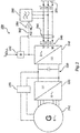
- FIG. 2 shows, in simplified form, an electrical harness 200 in FIG Fig. 1 shown, wind turbine according to the invention.
- the electrical train 200 has a 6-phase ring generator 210, which is set in rotary motion by the wind via a mechanical drive train of the wind energy installation in order to generate a 6-phase alternating current.
- the 6-phase electrical alternating current is transferred from the generator 210 to the rectifier 220, which is connected to the 3-phase inverter 240 via a DC voltage intermediate circuit 230.
- the 6-phase ring generator 210 which is designed as a synchronous generator, is electrically excited by the excitation 250 from the DC voltage intermediate circuit 230.
- the electrical phase 200 thus has a full converter concept in which the 3-phase inverter 240 is used to feed into the network 270.
- This network 270 is usually a wind farm network which feeds into an electrical supply network via a wind farm transformer. Feeding directly into the electrical supply network instead of the parking network 270 is also possible.
- a transformer can also be provided for feeding into the network 270.
- the inverter 240 In order to generate the three-phase current I 1 , I 2 , I 3 for each of the phases U, V, W, the inverter 240 is controlled with a tolerance band method. The control takes place via the controller 242 which, by means of a current detection 244, detects each of the three currents I1, I2, I3 provided or generated by the inverter 240 at the inverter output 246.
- the controller is thus set up to control each phase of the inverter individually by means of the current detection 244.
- the controller 242 can use a current setpoint value Preset Isoll as a function of which the currents I 1 , I 2 , I 3 are controlled.
- the current setpoint Isoll is preferably calculated and specified individually for each phase U, V, W in the system.
- the currents I 1 , I 2 , I 3 generated in this way are also referred to as inverter currents or inverter currents.
- the inverter 240 is further coupled at its inverter output 246 to an active filter 260 in order to filter the inverter current I 1 , I 2 , I 3 provided at the inverter output 241 and thereby a filtered alternating current I * 1 , I * 2 , I * 3 to be provided for feeding into the electrical supply network.
- the active filter 260 is controlled as a function of the detected switching operations of the switches of the inverter 240.
- the fact that the active filter 260 is controlled as a function of these switching operations is indicated by the signal line 262, which transfers the control signals from the controller 242 to the switches of the inverter 240 to the active filter 260 as well.
- a collective evaluation device 264 is provided, which is set up to record the control signals by means of the signal line 262 and other signals AS, such as the intermediate circuit voltage U DC and the current setpoint I soll , and to evaluate them.
- the collective evaluation device 264 then controls the active filter 260 as a function of the control signals detected and evaluated in this way and further signals AS.
- the active filter 260 has a low-pass behavior, the active filter 260 being controlled by means of the control signals for the switches of the inverter 240.
- Fig. 3 shows schematically the structure 300 of an inverter for providing an inverter current by means of a tolerance band method.
- Fig. 3 a part of the in Fig. 2 shown electrical strand.
- the structure 300 has a DC voltage intermediate circuit 330, which is connected to the generator of a wind energy installation via a rectifier.
- the DC voltage intermediate circuit 330 has a first potential U DC + and a second potential Udc- with a center tap M.
- a capacitor with the capacitance C 1 , C 2 is arranged between the center tap M and the two potentials U DC + , U DC , to store energy in the DC voltage intermediate circuit 330 and to smooth the DC voltage 2U DC accordingly.
- the inverter 340 which is connected to the DC voltage intermediate circuit 330, generates a separate current I 1 , I 2 , I 3 at the output 346 of the inverter 340 for each of the three phases U, V, W.
- the inverter 340 has this for each of the three phases U, V, W each have an upper switch T 1 , T 3 , T 5 and a lower switch T 2 , T 4 , T 6 , the upper and lower switches T 1 , T 2 , T 3 , T 4 , T 5 , T 6 can be controlled in particular via the controller 342 by means of a tolerance band method.
- the controller 342 itself operates with a current-controlled tolerance band method.
- the controller 342 records the currents I 1 , I 2 , I 3 generated or provided by the inverter 340 at the output 346 of the inverter 340 by means of a current recorder 344.
- the currents I 1 , I 2 , I 3 recorded in this way are compared with a target value.
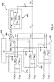
- Fig. 4 shows schematically the coupling 400 of the active filter 460 with the switches OB 11 , UB 11 , OB 21 , UB 21 , OB 31 , UB 31 of several inverter modules 410, 420, 430, whose inverter module currents I 11 , I 12 , I 13 correspond to the Superimpose inverter current I 1 on phase U.
- Fig. 4 thus shows a single-phase view of phase U of a three-phase system, comprising phases U, V and W.
- the inverter modules 410, 420, 430 are each connected on the DC side to a DC voltage intermediate circuit, which is indicated by the terminal voltage U DC + , U DC- .
- the individual inverter modules 410, 420, 430 are activated by means of the activation signals A 11 , A 21 , A 31 .
- the control signals A 11 , A 21 , A 31 give the upper switch OB 11 , OB 21 , OB 31 and the lower switches UB 11 , UB 21 , UB 31 a corresponding switching state.
- the inverter module 410 has the switching state +1, ie that the upper switch OB 11 is active and the lower switch UB 11 is inactive.
- the inverter module 420 has the switching state -1, that is, the upper switch OB 21 is inactive and the lower switch UB 21 is active.
- the inverter module 430 has the switching state -1, that is, the upper switch OB 31 is inactive and the lower switch UB 31 is active.
- control signals A 11 , A 21 , A 31 as well as the intermediate circuit voltage U DC and the current setpoint I soll for the inverter modules 410, 420 430 are fed to the collective evaluation device 464, which transfers them to the control unit 468 of the active filter 460.
- the control signals A 11 , A 21 , A 31 are transferred to the collective evaluation device 464 as switching states, namely in the current state shown as an example as the three switching states +1, -1 and -1.
- the collective evaluation 464 is preferably set up to reproduce both the individual switching states of the individual inverter modules 410, 420, 430 and a total switching state ⁇ of all inverters 410, 420, 430.
- the sum switching state is ⁇ -1.
- the controller 468 of the active filter can then determine the rise of the corresponding edges of the tolerance band method of the inverter modules 410, 420, 430 and accordingly control the switches of the active filter using the control signal S F so that the filtered alternating current I C has fewer harmonics than the inverter current I 1 .
- control unit 468 controls the switches IG 11 , IG 12 of the active filter 460 as a function of the three switching states +1, -1 and -1 as well as the intermediate circuit voltage U DC and the current setpoint Isoll using the control signal SF, which also has a switching state +1 for the switches IG 11 , IG 12 of the active filter 460 presets.
- the active filter 460 uses a DC voltage source C F to generate a filter current I F , which is superimposed with an inverter current I 1 to form a filtered alternating current I * 1 .
- the switches IG 11 , IG 12 of the active filter 460 can be controlled, for example, by means of a look-up table in which the switching states of the switches IG 11 , IG 12 of the active filter 460 are dependent on the switching states of the upper and lower switches OB 11 , OB 21 , OB 31 , UB 11 , UB 21 , UB 31 of the inverter modules 410, 420, 430 are stored.
- the look-up table can either be stored in the collective evaluation device 464 or in the controller 468 of the active filter 460. Such a look-up table that is also referred to as a control table, is below in the Figure 5 shown as an example.
- Fig. 5 shows schematically a control table 500 of a collective evaluation device according to the invention.
- Fig. 5 thereby a control table of an in Fig. 4 shown collective evaluation device.
- control signals A 11 , A 21 , A 31 of the upper and lower switches, the sum switching state ⁇ and the control signal S F of the active filter are plotted.
- the individual columns 520, 530, 540, 560 also have the corresponding switching states of the control signals A 11 , A 21 , A 31 , S F.
- Column 550 shows the corresponding sum switching state ⁇ .
- Line 570 shows the Figure 4 accordingly that the control signals A 11 , A 21 , A 31 , which include the switching states +1, -1 and -1, result in the switching state +1 being transmitted to the switches of the active filter.
Description
Die vorliegende Erfindung betrifft ein Verfahren zum Einspeisen eines elektrischen Wechselstromes in ein elektrisches Versorgungsnetz mittels einer Windenergieanlage sowie eine Windenergieanlage, die wenigstens einen Wechselrichter mit einem Wechselrichterausgang umfasst, der mit einem aktiven Filter gekoppelt ist.The present invention relates to a method for feeding an electrical alternating current into an electrical supply network by means of a wind energy installation and a wind energy installation which comprises at least one inverter with an inverter output which is coupled to an active filter.
Es ist besonders für Windenergieanlagen bekannt, elektrischen Wechselstrom unter der Verwendung von elektrischen Wechselrichtern zu erzeugen bzw. elektrischen Wechselstrom mittels elektrischer Wechselrichter in das elektrische Versorgungsnetz einzuspeisen.It is known in particular for wind power plants to generate alternating electrical current using electrical inverters or to feed alternating electrical current into the electrical supply network by means of electrical inverters.
Hierzu weisen Windenergieanlage üblicherweise wenigstens einen elektrischen Generator zum Erzeugen eines elektrischen Wechselstromes auf. Der vom Generator erzeugte elektrische Wechselstrom wird dann zum Einspeisen in das elektrische Versorgungsnetz mittels wenigstens eines Wechselrichters so gerichtet, dass der vom Generator erzeugte elektrische Wechselstrom dann den Anforderungen des elektrischen Versorgungsnetzes genügt.For this purpose, wind power plants usually have at least one electrical generator for generating an electrical alternating current. The electrical alternating current generated by the generator is then directed for feeding into the electrical supply network by means of at least one inverter so that the electrical alternating current generated by the generator then meets the requirements of the electrical supply network.
Der elektrische Wechselrichter ist dabei üblicherweise mehrphasig ausgebildet und ist zumeist in Windenergieanlagen großer Leistung modular ausgeführt, d.h. der Wechselrichter weist eine Vielzahl von Wechselrichtermodulen auf, die gemeinsam den elektrischen Wechselrichter ausbilden.The electrical inverter is usually multi-phase and is mostly designed in a modular fashion in large-capacity wind turbines, i.e. the inverter has a plurality of inverter modules which together form the electrical inverter.
Elektrische Wechselrichter weisen aber auch eine Reihe von Nachteilen auf, beispielsweise ist der von einem elektrischen Wechselrichter bereitgestellte elektrische Wechselstrom oberschwingungsbehaftet, d.h. der elektrische Wechselstrom bzw. der elektrische Wechselrichterstrom weist eine Vielzahl von Oberschwingungen verschiedenster Ordnungen auf, die seitens des elektrischen Versorgungsnetzes unerwünscht sind.However, electrical inverters also have a number of disadvantages, for example the electrical alternating current provided by an electrical inverter is subject to harmonics, ie the electrical alternating current or the electrical Inverter current has a large number of harmonics of the most varied orders, which are undesirable on the part of the electrical supply network.
Um solche, insbesondere unerwünschten, Oberschwingungen zu minimieren, können beispielsweise aktive oder passive Filter am Ausgang des elektrischen Wechselrichters vorgesehen bzw. angeordnet werden, deren Aufgabe es ist, die unerwünschten Oberschwingung heraus zu filtern bzw. den vom elektrischen Wechselrichter bereitgestellten Wechselstrom zu glätten.In order to minimize such, especially undesired, harmonics, active or passive filters, for example, can be provided or arranged at the output of the electrical inverter, the task of which is to filter out the undesired harmonics or to smooth the alternating current provided by the electrical inverter.
Passive Filter sind dabei im einfachsten Fall aus einer Kombination von Kapazitäten, Impedanzen und/oder Induktivitäten ausgebildet. Passive Filter weisen also eine Kombination von passiven Bauteilen auf, nämlich Kondensatoren, Widerständen und/oder Spulen. Üblicherweise werden solche passiven Filter ferner einmalig für ihr Einsatzgebiet konfiguriert.In the simplest case, passive filters are formed from a combination of capacitances, impedances and / or inductances. Passive filters therefore have a combination of passive components, namely capacitors, resistors and / or coils. Such passive filters are usually also configured once for their area of application.
Aktive Filter weisen zusätzlich wenigstens eine weitere aktive Komponente auf, also eine Komponente die steuerbar ist und im Falle eines aktiven Filters auch gesteuert wird. Diese aktive Komponente kann beispielsweise ein Leistungsschalter sein, also ein IGBT oder ein MOSFET. Zudem werden aktive Filter einmalig für ihr Einsatzgebiet initialisiert und im Laufe des Betriebs entsprechend nachkonfiguriert, ihre Steuerung wird also ständig ihrem Einsatzgebiet neu angepasst.Active filters additionally have at least one further active component, that is to say a component that can be controlled and, in the case of an active filter, is also controlled. This active component can be, for example, a power switch, that is to say an IGBT or a MOSFET. In addition, active filters are initialized once for their area of application and reconfigured accordingly in the course of operation, so their control is constantly adapted to their area of application.
Nachteilig bei den bisher bekannten Filtern sind insbesondere der eingeschränkte Arbeitsbereich bei passiven Filtern bzw. die hohen Signallaufzeiten bei aktiven Filtern, die dazu führen, dass der vom Generator erzeugte, vom Wechselrichter gerichtete und vom Filter gefilterte elektrische Wechselstrom trotz dieser Vorkehrungen Oberschwingungen aufweist, die den Anforderungen des elektrischen Versorgungsnetzes nicht genügen, insbesondere in Ländern mit hohen Anforderungen, die insbesondere ein schwaches elektrisches Versorgungsnetz aufweisen, wie beispielsweise Brasilien.Disadvantages of the filters known up to now are in particular the restricted working range with passive filters and the long signal propagation times with active filters, which lead to the electrical alternating current generated by the generator, directed by the inverter and filtered by the filter, having harmonics despite these precautions Requirements of the electrical supply network are not sufficient, especially in countries with high requirements, which in particular have a weak electrical supply network, such as Brazil.
Das Deutsche Patent- und Markenamt hat in der Prioritätsanmeldung zur vorliegenden Anmeldung folgenden Stand der Technik recherchiert:
Der vorliegenden Erfindung liegt somit die Aufgabe zugrunde, zumindest eines der oben genannten Probleme zu adressieren. Insbesondere soll eine Lösung vorgeschlagen werden, die ein für Windenergieanlagen geeignetes Filtern eines elektrischen Wechselstroms bzw. eines elektrischen Wechselrichterstroms ermöglicht. Zumindest soll aber zu bisher bekannten Konzepten eine alternative Lösung vorgeschlagen werden.The present invention is therefore based on the object of addressing at least one of the above-mentioned problems. In particular, a solution is to be proposed which includes filtering an electrical alternating current which is suitable for wind energy installations or an electrical inverter current allows. At least an alternative solution to previously known concepts should be proposed.
Erfindungsgemäß wird somit ein Verfahren zum Einspeisen eines elektrischen Wechselstromes in ein elektrisches Versorgungsnetz mittels einer Windenergieanlage nach Anspruch 1 vorgeschlagen. Demnach umfasst die Windenergieanlage wenigstens einen Wechselrichter mit einem Wechselrichterausgang zum Bereitstellen eines elektrischen Wechselrichterstromes und ein an den Wechselrichterausgang gekoppeltes aktives Filter.According to the invention, a method for feeding an electrical alternating current into an electrical supply network by means of a wind energy installation is proposed. Accordingly, the wind energy installation comprises at least one inverter with an inverter output for providing an electrical inverter current and an active filter coupled to the inverter output.
Der Wechselrichter ist somit dazu eingerichtet, an seinem Wechselrichterausgang einen Wechselrichterstrom, insbesondere einen mehrphasigen Wechselstrom, bereitzustellen bzw. abzugeben.The inverter is thus set up to provide or output an inverter current, in particular a polyphase alternating current, at its inverter output.
Das aktive Filter ist zudem dazu eingerichtet, den an dem Wechselrichterausgang bereitgestellten Wechselrichterstrom zu filtern, insbesondere um dadurch einen gefilterten Wechselstrom zum Einspeisen in das elektrische Versorgungsnetz bereitzustellen bzw. diesen bevorzugt mittels eines Transformators in das elektrische Versorgungsnetz einzuspeisen. Das aktive Filter ist somit bevorzugt zwischen dem wenigstens einen elektrischen Wechselrichter und dem elektrischen Versorgungsnetz angeordnet.The active filter is also designed to filter the inverter current provided at the inverter output, in particular in order to thereby provide a filtered alternating current for feeding into the electrical supply network or preferably feeding this into the electrical supply network by means of a transformer. The active filter is thus preferably arranged between the at least one electrical inverter and the electrical supply network.
Besonders bevorzugt weist die Windenergieanlage hierfür ein Vollumrichterkonzept auf, wobei unter einem Vollumrichterkonzept insbesondere zu verstehen ist, dass der gesamte von der Windenergieanlage erzeugte elektrische Strom über einen Wechselrichter oder eine Anordnung mehrerer Wechselrichter bzw. Wechselrichtermodule so geführt wird, dass der gesamte in das elektrische Versorgungsnetz eingespeiste Strom über diesen Wechselrichter bzw. diese Anordnung mehrerer Wechselrichter bzw. Wechselrichtermodule geführt wurde.The wind power plant particularly preferably has a full converter concept for this purpose, with a full converter concept being understood in particular to mean that the entire electrical current generated by the wind power plant is routed via an inverter or an arrangement of several inverters or inverter modules in such a way that the entire power is fed into the electrical supply network fed-in current was passed through this inverter or this arrangement of several inverters or inverter modules.
In einem ersten Schritt stellt der elektrische Wechselrichter nun durch Schalthandlungen wenigstens eines Schalters an seinem Ausgang einen Wechselrichterstrom bereit. Der Wechselrichter richtet somit den vom Generator erzeugten Strom oder einen Teil davon, um am Wechselrichterausgang einen Wechselstrom bereitzustellen bzw. abzugeben. Der so am Wechselrichterausgang bereitgestellte Wechselrichterstrom ist dabei insbesondere ein dreiphasiger Wechselstrom.In a first step, the electrical inverter now provides an inverter current at its output by switching operations of at least one switch. The inverter thus directs the current generated by the generator or a part thereof in order to provide or output an alternating current at the inverter output. The inverter current thus provided at the inverter output is in particular a three-phase alternating current.
Der elektrische Wechselrichter ist hierfür bevorzugt dreiphasig ausgebildet und weist zum Erzeugen des elektrischen Wechselrichterstromes wenigstens einen Ober- und einen Unterschalter für jede der Phasen auf. Die Schalter des Wechselrichters können dabei beispielsweise über ein Toleranzbandverfahren angesteuert werden, um den Wechselrichterstrom zu erzeugen bzw. diesen am Wechselrichterausgang bereitzustellen.For this purpose, the electrical inverter is preferably designed to be three-phase and has at least one upper and one upper current for generating the electrical inverter current Sub-switch for each of the phases. The switches of the inverter can, for example, be controlled using a tolerance band method in order to generate the inverter current or to make it available at the inverter output.
Unabhängig von der Art des Steuerverfahrens wird dabei die Steuerung des Wechselrichters bzw. die Steuerung der Schalter des Wechselrichters von einem Kontroller übernommen, der die Schalter des Wechselrichters mittels Ansteuerungssignale so ansteuert, dass sich am Wechselrichterausgang ein entsprechender Wechselrichterstrom einstellt.Regardless of the type of control method, the control of the inverter or the control of the switches of the inverter is taken over by a controller, which controls the switches of the inverter by means of control signals so that a corresponding inverter current is set at the inverter output.
In einem zweiten Schritt werden erfindungsgemäß die Schalthandlungen des Wechselrichters erfasst. Es werden also die Schalthandlungen der einzelnen Schalter des Wechselrichters überwacht. Dies kann beispielsweise durch ein direktes Erfassen eines Schaltzustandes des entsprechenden Schalters erfolgen oder durch einen Abgriff der Ansteuersignale die vom Kontroller an die Schalter übermittelt werden. Sendet der Kontroller beispielsweise ein Ansteuersignal an einen Schalter des Wechselrichters, so wird dieses Signal abgegriffen und insbesondere dem aktiven Filter zugeführt bzw. übermittelt. Bevorzugt erhält das aktive Filter somit dieselben Signale, wie die Schalter des elektrischen Wechselrichters.In a second step, according to the invention, the switching operations of the inverter are recorded. The switching operations of the individual switches of the inverter are therefore monitored. This can be done, for example, by directly detecting a switching state of the corresponding switch or by tapping the control signals that are transmitted from the controller to the switches. If, for example, the controller sends a control signal to a switch of the inverter, this signal is picked up and, in particular, fed to or transmitted to the active filter. The active filter thus preferably receives the same signals as the switches of the electrical inverter.
Anschließend wird das aktive Filter in Abhängigkeit der erfassten Schalthandlungen gesteuert, um den vom Wechselrichter am Wechselrichterausgang bereitgestellten Wechselrichterstrom zu filtern, insbesondere um dadurch einen gefilterten Wechselstrom zu erschaffen.The active filter is then controlled as a function of the detected switching operations in order to filter the inverter current provided by the inverter at the inverter output, in particular in order to create a filtered alternating current.
Der so erschaffene bzw. gefilterte Wechselstrom kann dann beispielsweise mit weiteren Wechselströmen überlagert und über einen Transformator in ein Windparknetz und/oder in ein elektrisches Versorgungsnetz eingespeist werden.The alternating current created or filtered in this way can then, for example, be superimposed with further alternating currents and fed into a wind farm network and / or into an electrical supply network via a transformer.
Es wird somit insbesondere vorgeschlagen, dass das aktive Filter direkt in Abhängigkeit der Ansteuersignale für die Schalter des Wechselrichters gesteuert wird. Der Wechselrichter bzw. der Kontroller des Wechselrichters teilt dem aktiven Filter also bevorzugt die Ansteuersignale für die Schalter mit, beispielsweise direkt mit demselben Signal oder weiter bevorzugt indirekt über einen Signalabgriff der Ansteuersignale. Durch ein solches Vorgehen liegen nahezu dieselben Signallaufzeiten zwischen dem Kontroller des Wechselrichters und den Schaltern des Wechselrichters sowie zwischen dem Kontroller des Wechselrichters und dem aktiven Filter vor. Ein solcher Aufbau bzw. eine solche Vorgehensweise ermöglicht insbesondere eine Möglichkeit zum Filtern eines Wechselrichterstromes, bei der keine zeitlichen Verzögerungen in den Steuersignalen zwischen dem zu filternden Wechselstrom und der aktiven Filterung vorliegen. Das aktive Filter ist somit dazu eingerichtet, einen von einem Wechselrichter bereitgestellten Wechselrichterstrom zu filtern ohne diesen messen zu müssen.It is therefore proposed in particular that the active filter be controlled directly as a function of the control signals for the switches of the inverter. The inverter or the controller of the inverter therefore preferably notifies the active filter of the control signals for the switches, for example directly with the same signal or more preferably indirectly via a signal tap of the control signals. With such a procedure, there are almost the same signal propagation times between the controller of the inverter and the switches of the inverter as well as between the controller of the inverter and the active filter. Such a structure or such a procedure enables in particular a possibility of filtering an inverter current, in which there are no time delays in the control signals between the alternating current to be filtered and the active filtering. The active filter is thus set up to filter an inverter current provided by an inverter without having to measure it.
Besonders vorteilhaft hierbei ist ferner, dass das aktive Filter nicht initialisiert und nachkonfiguriert werden muss wie bei bisher bekannten Verfahren oder der Strom laufend gemessen werden muss, um die Abweichungen von einem Soll-Wert zu erfassen.It is also particularly advantageous here that the active filter does not have to be initialized and reconfigured as in previously known methods, or the current has to be measured continuously in order to detect the deviations from a setpoint value.
Das erfindungsgemäße Verfahren ermöglicht es somit insbesondere, einen aktiven Filter so zu steuern, dass die Oberschwingungen eines Wechselrichterstromes minimiert werden, ohne dass der vom Wechselrichter bereitgestellte Wechselstrom gemessen oder der aktive Filter initialisiert und nachkonfiguriert werden muss. Das vorgeschlagene Verfahren schafft somit wenigstens eine Möglichkeit zur Filterung von Oberschwingungen, bei der der aktive Filter nur einmalig initialisiert werden muss. Unter Initialisierung ist dabei insbesondere die erstmalige Konfiguration des aktiven Filters im Zusammenspiel mit dem bzw. den entsprechenden Wechselrichtern zu verstehen.The method according to the invention thus makes it possible in particular to control an active filter in such a way that the harmonics of an inverter current are minimized without having to measure the alternating current provided by the inverter or initialize and reconfigure the active filter. The proposed method thus creates at least one possibility for filtering harmonics, in which the active filter only needs to be initialized once. Initialization is to be understood in particular as the initial configuration of the active filter in interaction with the corresponding inverter or inverters.
Vorzugsweise erfolgt das Steuern des aktiven Filters so, dass der in das elektrische Versorgungsnetz eingespeiste elektrische Wechselstrom einen verringerten Oberschwingungsanteil gegenüber dem elektrischen Wechselrichterstrom aufweist.The active filter is preferably controlled in such a way that the electrical alternating current fed into the electrical supply network has a reduced harmonic component compared to the electrical inverter current.
Das aktive Filter wird somit so gesteuert, dass der gefilterte Wechselstrom, der in das elektrische Versorgungsnetz eingespeist wird, weniger Oberschwingung aufweist, als der vom Wechselrichter bereitgestellte Wechselrichterstrom. Hierdurch können beispielsweise alle Oberschwingungen des bereitgestellten Wechselrichterstromes oder nur bestimmte Oberschwingungen des bereitgestellten Wechselrichterstromes minimiert werden.The active filter is thus controlled in such a way that the filtered alternating current that is fed into the electrical supply network has fewer harmonics than the inverter current provided by the inverter. In this way, for example, all harmonics of the inverter current provided or only certain harmonics of the inverter current provided can be minimized.
Es wird somit eine Möglichkeit bereitgestellt Oberschwingungen gezielt und nach Bedarf zu minimieren. Beispielsweise kann das aktive Filter dazu eingerichtet sein, Oberschwingungen der 3. Ordnung zu filtern, demnach die Oberschwingungen anderer Ordnungen dann gleich und/oder sogar größer sind.A possibility is thus made available to minimize harmonics in a targeted manner and as required. For example, the active filter can be set up to filter harmonics of the 3rd order, so that the harmonics of other orders are then the same and / or even greater.
Das aktive Filter ist somit bevorzugt in Abhängigkeit des elektrischen Versorgungsnetzes bzw. den Anforderungen des elektrischen Versorgungnetzes konfigurierbar und/oder initialisierbar. Dies ist besonders vorteilhaft in Hinsicht auf unterschiedliche nationale oder regionale Anforderungen, da zum Aufstellen einer Windenergieanlage an einem beliebigen Standort lediglich das aktive Filter einmalig initialisiert werden muss.The active filter can thus preferably be configured and / or initialized as a function of the electrical supply network or the requirements of the electrical supply network. This is particularly advantageous in terms of different national or regional requirements, since only the active filter has to be initialized once to set up a wind turbine at any location.
Vorzugweise weisen die Schalthandlungen des wenigstens einen Schalters eine Schaltfrequenz auf und das Erfassen der Schalthandlungen erfolgt mit einer Tastfrequenz, wobei die Tastfrequenz wenigstens doppelt so groß, insbesondere wenigstens fünfmal so groß, bevorzugt wenigstens zehnmal so groß, ist, wie die Schaltfrequenz der zu erfassenden Schalthandlung des Schalters.The switching operations of the at least one switch preferably have a switching frequency and the switching operations are detected with a scanning frequency, the scanning frequency being at least twice as high, in particular at least five times as high, preferably at least ten times as high, as the switching frequency of the switching operation to be detected of the switch.
Die Schalter des elektrischen Wechselrichters weisen beispielsweise zum Bereitstellen des elektrischen Wechselstromes am Wechselrichterausgang eine Schaltfrequenz von 2 kHz auf. Die Schalter des Wechselrichters bekommen somit wenigstens 2000 Ansteuersignale pro Sekunde von dem Kontroller des Wechselrichters übermittelt. Die Ansteuersignale selbst werden dann mittels einer Tastfrequenz abgetastet bzw. mit einer erhöhten bzw. höheren Frequenz an das aktive Filter gesendet, die wenigstens doppelt so groß ist, wie die Schaltfrequenz, bevorzugt zehnmal so groß ist, wie die Schaltfrequenz.The switches of the electrical inverter have a switching frequency of 2 kHz, for example, to provide the electrical alternating current at the inverter output. The switches of the inverter thus receive at least 2000 control signals per second from the controller of the inverter. The control signals themselves are then sampled by means of a sampling frequency or sent to the active filter with an increased or higher frequency which is at least twice as large as the switching frequency, preferably ten times as large as the switching frequency.
Vorzugsweise erfolgt das Steuern des aktiven Filters abhängig eines die Schalthandlungen des wenigstens einen Schalters auslösenden Ansteuersignals und außerdem oder alternativ erfolgt das Steuern des aktiven Filters abhängig einer die Schalthandlungen des wenigstens einen Schalters auslösenden Steuerspannung.The active filter is preferably controlled as a function of a control signal that triggers the switching operations of the at least one switch, and the active filter is also or alternatively controlled as a function of a control voltage that triggers the switching operations of the at least one switch.
Das aktive Filter erfasst somit bevorzugt die Ansteuersignale der Schalter des Wechselrichters bzw. das aktive Filter bekommt die Ansteuersignale für die Schalter des Wechselrichters durch den Kontroller des Wechselrichters direkt übermittelt. Das aktive Filter wird somit mit denselben Signalen gesteuert wie die Schalter des Wechselrichters.The active filter thus preferably detects the control signals of the switches of the inverter or the active filter receives the control signals for the switches of the inverter transmitted directly by the controller of the inverter. The active filter is thus controlled with the same signals as the switches of the inverter.
Außerdem oder alternativ kann das Steuern des aktiven Filters auch in Abhängigkeit einer Steuerspannung der Schalter erfolgen, beispielsweise kann hierfür die Gate-Spannung des Halbleiters erfasst bzw. gemessen werden.In addition or as an alternative, the active filter can also be controlled as a function of a control voltage of the switches, for example the gate voltage of the semiconductor can be detected or measured for this purpose.
Vorzugsweise wird der wenigstens eine Wechselrichter mittels eines Toleranzbandverfahrens angesteuert, um den Wechselrichterstrom am Wechselrichterausgang bereitzustellen und das aktive Filter filtert den Strom den Wechselrichterstrom abhängig der vom Toleranzbandverfahren erzeugten Schalthandlungen des wenigstens einen Schalters. Der elektrische Wechselrichter wird somit in Abhängigkeit eines Toleranzbandverfahrens angesteuert bzw. durch ein Toleranzbandverfahren gesteuert.The at least one inverter is preferably controlled by means of a tolerance band method in order to provide the inverter current at the inverter output and the active filter filters the current, the inverter current depending on the switching operations of the at least one switch generated by the tolerance band method. The electrical inverter is thus activated as a function of a tolerance band method or controlled by a tolerance band method.
Beim Toleranzbandverfahren wird um eine sinusförmige Funktion, die dem gewünschten Ausgangsstrom des Wechselrichters entspricht, ein Toleranzband gelegt, welches eine untere Bandgrenze und eine obere Bandgrenze aufweist. Zur Durchführung des Toleranzbandverfahrens wird ferner der erzeugte Ausgangsstrom erfasst und mit dem Toleranzband, also der unteren und oberen Bandgrenze, verglichen. Befindet sich der Strom in der positiven Halbwelle und erreicht die untere Bandgrenze, wird ein Schaltimpuls mittels eines Ansteuersignals ausgelöst und der entsprechende Schalter des Wechselrichters ändert den Ausgangsstrom. Erreicht der erfasste Ausgangsstrom nun die obere Bandgrenze, wird der Schaltimpuls mittels eines weiteren Ansteuersignals beendet. Befindet sich der Strom in der negativen Halbwelle und erreicht die obere Bandgrenze, wird ein Schaltimpuls mit eines weiteren Ansteuersignals ausgelöst und der entsprechende Schalter des Wechselrichters ändert den Ausgangsstrom. Erreicht der erfasste Ausgangsstrom nun die untere Bandgrenze, wird der Schaltimpuls mittels eines weiteren Ansteuersignals beendet. Im Ergebnis variiert der Strom innerhalb des Toleranzbandes um den vorgegebenen, idealisierten sinusförmigen Verlauf, wobei die Schalter des Wechselrichters ständig an- und wieder ausgehen. Die Schalter weisen dabei eine variable Schaltfrequenz auf, die im Wesentlichen von der Breite des Toleranzbands abhängt.In the tolerance band method, a tolerance band with a lower band limit and an upper band limit is placed around a sinusoidal function that corresponds to the desired output current of the inverter. To carry out the tolerance band method, the output current generated is also recorded and compared with the tolerance band, that is to say the lower and upper band limits. If the current is in the positive half-wave and reaches the lower band limit, a switching pulse is triggered by a control signal and the corresponding switch of the inverter changes the output current. If the detected output current now reaches the upper band limit, the switching pulse is terminated by means of a further control signal. If the current is in the negative half-wave and reaches the upper band limit, a switching pulse is triggered with another control signal and the corresponding switch of the inverter changes the output current. If the recorded output current now reaches the lower band limit, the switching pulse is ended by means of a further trigger signal. As a result, the current varies within the tolerance band around the specified, idealized sinusoidal curve, with the inverter switches constantly on and off again. The switches have a variable switching frequency which essentially depends on the width of the tolerance band.
Besonders vorteilhaft bei der Verwendung eines Toleranzbandverfahrens ist, dass die auftretenden Amplituden der Oberschwingungen des Wechselrichterstromes unterhalb von 1% bezogen auf den Nennstrom liegen und das aktive Filter somit deutlich weniger große Stromspitzen filtern muss als beispielsweise bei einem puls-weiten-modulierten Wechselrichterstrom.When using a tolerance band method, it is particularly advantageous that the amplitudes of the harmonics of the inverter current are below 1% in relation to the nominal current and the active filter therefore has to filter significantly fewer large current peaks than, for example, with a pulse-width modulated inverter current.
Somit ergeben sich für das erfindungsgemäße Verfahren besonders vorteilhafte Synergien in Bezug auf Wechselrichter, die mittels eines Toleranzbandverfahrens gesteuert werden. Beispielsweise kann ein aktives Filter bei gleicher Baugröße dazu verwendet werden, mehrere toleranzbandverfahren-erzeugte Wechselrichterströme zu filtern.This results in particularly advantageous synergies for the method according to the invention with regard to inverters that are controlled by means of a tolerance band method. For example, an active filter of the same size can be used to filter several inverter currents generated by tolerance band methods.
Vorzugsweise erfolgt das Steuern des aktiven Filters ohne Berücksichtigung des bereitgestellten Wechselrichterstromes.The active filter is preferably controlled without taking into account the inverter current provided.
Das aktive Filter wird somit unabhängig von dem erzeugten Wechselrichterstrom gesteuert. Das aktive Filter weist also keine primären Mittel zum Erfassen des erzeugten Wechselrichterstromes auf. Auch weist das aktive Filter bevorzugt keinen Eingang auf, dessen Eingangsgröße der erzeugte Wechselrichterstrom ist. Gleichwohl kann zur Durchführung des Toleranzbandverfahrens der erzeugte Wechselrichterstrom erfasst werden. Dieser wird dann aber nicht dem aktiven Filter zur Durchführung des erfindungsgemäßen Verfahrens übergeben.The active filter is thus controlled independently of the inverter current generated. The active filter therefore has no primary means for detecting the generated inverter current on. The active filter also preferably does not have an input whose input variable is the generated inverter current. At the same time, the inverter current generated can be recorded to carry out the tolerance band method. However, this is then not transferred to the active filter for carrying out the method according to the invention.
Vorzugsweise erfolgt das Steuern des aktiven Filters in Abhängigkeit der erfassten Schalthandlungen, um wenigstens ein Oberschwingungsanteil des ersten Wechselstromes zu reduzieren, insbesondere einen Stromoberschwingungsanteil des ersten Wechselstromes zu minimieren, bevorzugt um einen Stromoberschwingungsanteil zu reduzieren, der ausgewählt ist aus der Liste umfassend: 1. Harmonische Stromoberschwingung bis 60. Harmonische Stromoberschwingung.The active filter is preferably controlled as a function of the detected switching operations in order to reduce at least one harmonic component of the first alternating current, in particular to minimize a current harmonic component of the first alternating current, preferably to reduce a current harmonic component which is selected from the list comprising: 1st harmonic Current harmonic up to 60th harmonic current harmonic.
Das aktive Filter ist somit dazu eingerichtet, wenigstens einen Oberschwingungsanteil zu reduzieren. Zudem ist das aktive Filter derart aufgebaut, dass es Frequenzen eines bestimmten Spektrums abschwächt, insbesondere Oberschwingung bis zur 60. Harmonischen Stromoberschwingung. Bevorzugt ist das aktive Filter somit dazu eingerichtet Oberschwingung bis zu 3 kHz zu filtern, also der 60. Oberschwingung einer Grundfrequenz von 50 Hz.The active filter is thus set up to reduce at least one harmonic component. In addition, the active filter is constructed in such a way that it attenuates frequencies of a certain spectrum, in particular harmonics up to the 60th harmonic current harmonic. The active filter is thus preferably set up to filter harmonics up to 3 kHz, that is to say the 60th harmonic of a fundamental frequency of 50 Hz.
Es wurde nämlich ferner erkannt, dass das erfindungsgemäße Verfahren bzw. der erfindungsgemäße Aufbau des Filters besonders günstig ist für Oberschwingungen bis zur 60. Ordnung.It was also recognized that the method according to the invention and the structure of the filter according to the invention are particularly favorable for harmonics up to the 60th order.
Vorzugsweise umfasst der elektrische Wechselrichter mehrere Wechselrichtermodule mit einem Wechselrichtermodulausgang zum Bereitstellen eines Wechselrichtermodulstromes und die Wechselrichtermodulausgänge sind so verschaltet, dass sich ihre Wechselrichtermodulströme zu dem Wechselrichterstrom überlagern, wobei eine Sammelauswerteeinrichtung vorgesehen ist, zum Erfassen und Auswerten von Ansteuersignalen der mehreren Wechselrichtermodule, und die Sammelauswerteeinrichtung das aktive Filter zum Filtern des Wechselrichterstromes ansteuert.The electrical inverter preferably comprises a plurality of inverter modules with an inverter module output for providing an inverter module current and the inverter module outputs are connected in such a way that their inverter module currents are superimposed on the inverter current, with a collective evaluation device being provided for detecting and evaluating control signals from the plurality of inverter modules, and the collective evaluation device activates active filters for filtering the inverter current.
Der Wechselrichter ist somit aus mehreren Modulen aufgebaut. Die Module selbst wiederum können aus einem vollständigen Wechselrichter ausgebildet sein, so dass unter wenigsten einem Wechselrichter auch eine Vielzahl von Wechselrichtern zu verstehen ist. Zudem ist das aktive Filter dazu eingerichtet, einen aus mehreren Wechselrichterströmen überlagerten Wechselrichterstrom zu filtern. Hierfür ist insbesondere eine Sammelauswerteeinrichtung vorgesehen, die die Ansteuersignale aller zu filternder Wechselrichter bzw. Wechselrichtermodule empfängt. Beispielsweise werden drei Wechselrichter bzw. drei Wechselrichtermodule mit einem aktiven Filter gefiltert. Sofern jeder Wechselrichter 6 Schalter aufweist, empfängt die Sammelauswerteeinrichtung 18 Ansteuersignale. Die Ansteuersignale werden dann innerhalb der Sammelauswerteeinrichtung beispielsweise mittels eines Look-Up-Tables ausgewertet, um das aktive Filter entsprechend anzusteuern, damit dieser den Gesamtstrom filtert. Bevorzugt erfasst die Sammelauswerteeinrichtung hierzu die Schaltzustände der einzelnen Schalter der Wechselrichtermodule.The inverter is thus made up of several modules. The modules themselves can in turn be formed from a complete inverter, so that at least one inverter is also to be understood as a multiplicity of inverters. In addition, the active filter is set up to filter an inverter current that is superimposed from several inverter currents. For this purpose, a collective evaluation device is provided in particular, which receives the control signals from all inverters or inverter modules to be filtered. For example, three inverters or three inverter modules are filtered with an active filter. If each inverter has 6 switches, the collective evaluation device 18 receives control signals. The control signals are then evaluated within the collective evaluation device, for example by means of a look-up table, in order to activate the active filter accordingly so that it filters the entire current. For this purpose, the collective evaluation device preferably detects the switching states of the individual switches of the inverter modules.
Vorzugsweise wird das aktive Filter in Abhängigkeit der erfassten Schalthandlungen und wenigstens zusätzlich in Abhängigkeit einer Zwischenkreisspannung des wenigstens einen Wechselrichters und/oder eines Stromsollwertes für den wenigstens einen Wechselrichter gesteuert.The active filter is preferably controlled as a function of the detected switching operations and at least additionally as a function of an intermediate circuit voltage of the at least one inverter and / or a current setpoint value for the at least one inverter.
Das aktive Filter erfasst somit zusätzlich die Zwischenkreisspannung und bevorzugt den Stromsollwert für den wenigstens einen Wechselrichter. Hierdurch wird insbesondere ermöglicht mittels des aktiven Filters gezielter auf Rippelströme zu reagieren und/oder den aktiven Filter gezielter auf den wenigstens einen Wechselrichter abzustimmen.The active filter thus additionally detects the intermediate circuit voltage and preferably the current setpoint for the at least one inverter. This makes it possible in particular to react more specifically to ripple currents by means of the active filter and / or to adapt the active filter more specifically to the at least one inverter.
Erfindungsgemäß wird zudem eine Windenergieanlage vorgeschlagen, umfassend wenigstens einen Wechselrichter mit einem Wechselrichterausgang zum Bereitstellen eines ersten Wechselstromes und ein an den Wechselrichterausgang gekoppeltes aktives Filter zum Filtern des Wechselrichterstromes, um einen gefilterten Wechselstrom zum Einspeisen in das elektrische Versorgungsnetz zu schaffen, wobei das aktive Filter dazu eingerichtet, in Abhängigkeit einer erfassten Schalthandlung wenigstens eines Schalters des Wechselrichters gesteuert zu werden, um den ersten Wechselstrom zu filtern und dadurch den gefilterten Wechselstrom zu schaffen.According to the invention, a wind energy installation is also proposed, comprising at least one inverter with an inverter output for providing a first alternating current and an active filter coupled to the inverter output for filtering the inverter current in order to create a filtered alternating current for feeding into the electrical supply network, the active filter for this purpose configured to be controlled as a function of a detected switching operation of at least one switch of the inverter in order to filter the first alternating current and thereby create the filtered alternating current.
Die erfindungsgemäße Windenergieanlage weist somit wenigstens einen Wechselrichter auf, der einen Wechselrichterstrom bereitstellt, der beispielsweise mittels eines Toleranzbandverfahrens erzeugt wird. Am Ausgang des Wechselrichters ist zudem ein aktives Filter angeordnet, welches dazu einrichtet ist, in Abhängigkeit der Schalthandlungen der Schalter des Wechselrichters, den am Ausgang des Wechselrichters bereitgestellten Wechselstrom zu filtern.The wind energy installation according to the invention thus has at least one inverter which provides an inverter current that is generated, for example, by means of a tolerance band method. At the output of the inverter, an active filter is also arranged, which is set up to filter the alternating current provided at the output of the inverter as a function of the switching operations of the switches of the inverter.
Somit wird insbesondere eine Windenergieanlage vorgeschlagen, die dazu eingerichtet ist, ein vorstehend oder nachstehend beschriebenes Verfahren zum Einspeisen eines elektrischen Wechselstromes auszuführen.Thus, in particular, a wind energy installation is proposed which is set up to carry out a method described above or below for feeding in an electrical alternating current.
Bevorzugt weist die Windenergieanlage zudem einen Windenergieanlagentransformator auf, der dazu eingerichtet ist, den vom aktiven Filter gefilterten Wechselstrom auf eine Versorgungsnetzspannung bzw. Windparknetzspannung hoch zu transformieren. Beispielsweise weist der Wechselrichterstrom eine Spannung von 1 kV auf und die Windparknetzspannung beträgt 10 kV. Das Übertragungsverhältnis des Windenergieanlagentransformators ist dann 1:10.The wind energy installation preferably also has a wind energy installation transformer which is set up to transform the alternating current filtered by the active filter up to a supply network voltage or wind farm network voltage. For example, the inverter current has a voltage of 1 kV and the wind farm grid voltage is 10 kV. The transmission ratio of the wind turbine generator is then 1:10.
Vorzugsweise weist die Windenergieanlage einen Kontroller zum Ansteuern des Wechselrichters auf, um ein vorstehend oder nachstehend beschriebenes Verfahren durchzuführen.The wind energy installation preferably has a controller for controlling the inverter in order to carry out a method described above or below.
Die Windenergieanlage umfasst somit einen Kontroller, der dazu eingerichtet ist, die Wechselrichter und insbesondere die Schalter, bevorzugt die Ober- und Unterschalter, der Wechselrichter anzusteuern, um einen Wechselrichterstrom am Wechselrichterausgang bereitzustellen.The wind energy installation thus comprises a controller which is set up to control the inverters and in particular the switches, preferably the upper and lower switches, of the inverters in order to provide an inverter current at the inverter output.
Hierzu übermittelt der Kontroller insbesondere Ansteuersignale an den Wechselrichter bzw. die Schalter des Wechselrichters oder der Wechselrichtermodule, wobei die Ansteuersignale bevorzugt ebenfalls an das aktive Filter übermittelt werden, um den am Wechselrichteraugang bereitgestellten Wechselrichterstrom des Wechselrichters bzw. der Wechselrichtermodule zu filtern und dadurch den gefilterten Wechselstrom zu schaffenFor this purpose, the controller transmits, in particular, control signals to the inverter or the switches of the inverter or the inverter modules, the control signals preferably also being transmitted to the active filter in order to filter the inverter current of the inverter or the inverter modules provided at the inverter input and thereby the filtered alternating current to accomplish
Vorzugsweise weist der wenigstens eine Wechselrichter wenigstens 6 Schalter auf, wobei jeweils zwei Schalter, insbesondere ein Ober- und ein Unterschalter, einen Strom für jeweils eine Phase des Wechselrichterstromes bereitstellen.The at least one inverter preferably has at least 6 switches, two switches in each case, in particular an upper switch and a lower switch, providing a current for one phase of the inverter current.
Der Wechselrichter bzw. die Wechselrichtermodule sind somit dazu eingerichtet, einen dreiphasigen Wechselstrom am Ausgang bereitstellen, wobei jeweils 2 Schalter für eine Phase vorgesehen sind.The inverter or the inverter modules are thus set up to provide a three-phase alternating current at the output, with two switches being provided for each phase.
Vorzugsweise ist der wenigstens eine Schalter des Wechselrichters bzw. die Schalter des Wechselrichters als IGBTs oder MOSFETs ausgebildet.The at least one switch of the inverter or the switches of the inverter is preferably designed as IGBTs or MOSFETs.
Die Schalter des Wechselrichters sind somit dazu eingerichtet, mit besonders hohen Schaltfrequenzen zu arbeiten, um einen Wechselrichterstrom bereitzustellen, der im Wesentlichen einem idealen Sinus entspricht bzw. dessen Abweichungen von einem idealen Sinus im Mittel kleiner sind als 5 % bezogen auf den Nennstrom.The switches of the inverter are thus set up to work with particularly high switching frequencies in order to provide an inverter current that essentially corresponds to an ideal sine or whose deviations from an ideal sine are on average less than 5% based on the nominal current.
Der Wechselrichter ist somit auch dazu eingerichtet, mittels eines Toleranzbandverfahrens angesteuert zu werden, wobei die Schalter des Wechselrichters beispielsweise eine Schaltfrequenz von bis zu 20 kHz aufweisen.The inverter is thus also set up to be controlled using a tolerance band method, the switches of the inverter, for example, having a switching frequency of up to 20 kHz.
Vorzugsweise wird der wenigstens eine Wechselrichter mittels eines Toleranzbandverfahrens angesteuert und das aktive Filter filtert den Wechselrichterstrom abhängig der vom Toleranzbandverfahren erzeugten Schalthandlungen des wenigstens einen Schalters.The at least one inverter is preferably controlled by means of a tolerance band method and the active filter filters the inverter current as a function of the switching operations of the at least one switch generated by the tolerance band method.
Vorzugsweise ist der Wechselrichter ein Leistungswechselrichter, insbesondere ein Leistungswechselrichter, der dazu eingerichtet ist, in einem Vollumrichterkonzept einer Windenergieanlage verwendet zu werden.The inverter is preferably a power inverter, in particular a power inverter, which is set up to be used in a full converter concept of a wind energy installation.
Der Wechselrichter ist somit dazu eingerichtet, elektrische Leistungen besonders bis zu 8 MW zu richten. Hierfür ist der Wechselrichter beispielsweise modular aufgebaut, d.h. er weist mehrere Wechselrichtermodule auf, die bevorzugt miteinander parallel verschalten sind, um einen Wechselrichterstrom bereitzustellen. Dieser so bereitgestellte Wechselstrom wird dann mit dem aktiven Filter gefiltert. Bevorzugt weist die Windenergieanlage dabei genau einen aktiven Filter auf. Es sind aber auch mehrere aktive Filter denkbar, beispielsweise wenn die Windenergieanlage mehrere baugleiche Wechselrichter aufweist, die jeweils in einem Leistungsschrank untergebracht sind. Dann weist alternativ jeder Leistungsschrank ein aktives Filter auf. Bevorzugt wird die Anzahl der aktiven Filter so gewählt, dass der von der Windenergieanlage in das elektrische Versorgungsnetz eingespeiste Wechselstrom den Anforderungen des elektrischen Versorgungsnetzes genügt.The inverter is thus set up to direct electrical power especially up to 8 MW. For this purpose, the inverter has a modular structure, for example, i.e. it has several inverter modules, which are preferably connected to one another in parallel in order to provide an inverter current. The alternating current provided in this way is then filtered with the active filter. The wind energy installation preferably has precisely one active filter. However, several active filters are also conceivable, for example if the wind energy installation has several structurally identical inverters, which are each accommodated in a power cabinet. Then, as an alternative, each power cabinet has an active filter. The number of active filters is preferably selected such that the alternating current fed into the electrical supply network by the wind energy installation meets the requirements of the electrical supply network.
Vorzugsweise weist das aktive Filter wenigstens ein aktives Bauteil auf, insbesondere wenigstens einen IGBT oder einen MOSFET, bevorzugt wenigstens einen Siliciumcarbid-IGBT oder einen Siliciumcarbid-MOSFET, das dazu eingerichtet ist, mit einer Taktfrequenz zu arbeiten, die bevorzugt größer ist als die Schaltfrequenz des wenigstens einen Schalters bzw. die größer ist als die Schaltfrequenz der Schalter multipliziert mit der Anzahl der Wechselrichtermodule des Wechselrichters.The active filter preferably has at least one active component, in particular at least one IGBT or a MOSFET, preferably at least one silicon carbide IGBT or a silicon carbide MOSFET, which is set up to work with a clock frequency that is preferably greater than the switching frequency of the at least one switch or which is greater than the switching frequency of the switch multiplied by the number of inverter modules of the inverter.
Die Taktfrequenz des aktiven Bauteils wird somit an die Anzahl der Schalter des Wechselrichters bzw. der Wechselrichtermodule angepasst, deren Wechselrichterstrom das aktive Filter filtern soll.The clock frequency of the active component is thus adapted to the number of switches of the inverter or the inverter modules whose inverter current is to be filtered by the active filter.
Hierbei wurde erkannt, dass die Taktfrequenz sowohl mit der Schaltfrequenz des Schalters als auch mit der Anzahl der Schalter des Wechselrichters erhöht werden muss, um einen gefilterten Wechselstrom zu erzeugen, der den Anforderungen des elektrischen Versorgungsnetzes genügt.It was recognized here that the clock frequency must be increased both with the switching frequency of the switch and with the number of switches in the inverter in order to generate a filtered alternating current that meets the requirements of the electrical supply network.
Insbesondere wird hierzu vorgeschlagen, dass die Taktfrequenz des aktiven Bauteils größer sein muss, als die Schalterfrequenz der Schalter multipliziert mit der Anzahl der Wechselrichtermodule.In particular, it is proposed for this purpose that the clock frequency of the active component must be greater than the switch frequency of the switches multiplied by the number of inverter modules.
Bevorzugt ist der bzw. sind die Schalter des aktiven Filters hierzu aus Siliciumcarbid-IGBTs oder Siliciumcarbid-MOSFETs oder anderen Transistoren ausgebildet, die insbesondere mit Takt- bzw. Schaltfrequenzen über 20 kHz betrieben werden können. Wenn beispielsweise das aktive Filter für 5 Wechselrichter zuständig ist, deren Schalter jeweils mit 20 kHz betrieben werden, so weist das aktive Filter, insbesondere der Schalter des aktiven Filters, eine Takt- bzw. Schaltfrequenz von größer als 100 kHz auf. Die Schaltfrequenz des aktiven Filter entspricht somit wenigstens N mal der Schalterfrequenz der N Wechselrichter.For this purpose, the switch (s) of the active filter is / are preferably formed from silicon carbide IGBTs or silicon carbide MOSFETs or other transistors, which can in particular be operated with clock or switching frequencies above 20 kHz. If, for example, the active filter is responsible for 5 inverters whose switches are each operated at 20 kHz, the active filter, in particular the switch of the active filter, has a clock frequency or switching frequency of greater than 100 kHz. The switching frequency of the active filter thus corresponds to at least N times the switching frequency of the N inverters.
Vorzugsweise umfasst der elektrische Wechselrichter mehrere Wechselrichtermodule mit einem Wechselrichtermodulausgang zum Abgeben eines Wechselrichtermodulstromes und die Wechselrichtermodulausgänge sind so verschaltet, dass sich ihre Wechselrichtermodulströme zu dem Wechselrichterstrom überlagern, wobei eine Sammelauswerteeinrichtung vorgesehen ist, zum Erfassen und Auswerten von Ansteuersignalen der Wechselrichtermodule, und die Sammelauswerteeinrichtung das aktive Filter zum Filtern des Wechselrichterstromes ansteuert.The electrical inverter preferably comprises several inverter modules with an inverter module output for outputting an inverter module current and the inverter module outputs are interconnected in such a way that their inverter module currents are superimposed on the inverter current, with a collective evaluation device being provided for detecting and evaluating control signals from the inverter modules, and the collective evaluation device the active Filter for filtering the inverter current controls.
Die Windenergieanlage weist somit mehrere Wechselrichter bzw. mehrere Wechselrichtermodule auf, deren Ausgangsströme mittels eines aktiven Filters gefiltert werden.The wind energy installation thus has several inverters or several inverter modules, the output currents of which are filtered by means of an active filter.
Hierzu ist eine Sammelauswerteinrichtung vorgesehen, die sämtliche Ansteuersignale der entsprechenden Wechselrichter bzw. Wechselrichtermodule erfasst und auswertet. Zudem ist die Sammelauswerteeinrichtung dazu eingerichtet, das aktive Filter in Abhängigkeit der erfassten Ansteuersignale so zu steuern, dass der durch das aktive Filter gefilterte Wechselrichterstrom weniger Oberschwingungen aufweist als der vom Wechselrichter bereitgestellte Wechselrichterstrom.A collective evaluation device is provided for this purpose, which records and evaluates all control signals from the corresponding inverters or inverter modules. In addition, the collective evaluation device is set up to control the active filter as a function of the detected control signals so that the inverter current filtered by the active filter has fewer harmonics than the inverter current provided by the inverter.
Dies kann beispielsweise mittels eines Look-Up-Tables bzw. einer Steuertabelle erfolgen, die unter Berücksichtigung der Anzahl der Wechselrichter bzw. der Wechselrichtermodule einmalig initialisiert wurde.This can take place, for example, by means of a look-up table or a control table that was initialized once, taking into account the number of inverters or inverter modules.
Vorzugsweise ist das aktive Filter so parallel zum Wechselrichterausgang verschaltet, dass das aktive Filter dazu eingerichtet ist, wenigstens eine Stromoberschwingung des ersten Wechselstromes zu filtern, insbesondere zu reduzieren.The active filter is preferably connected in parallel to the inverter output in such a way that the active filter is set up to filter, in particular to reduce, at least one current harmonic of the first alternating current.
Das aktive Filter ist somit dazu eingerichtet, Stromoberschwingung zu filtern.The active filter is thus set up to filter current harmonics.
Die vorliegende Erfindung wird nun nachfolgend exemplarisch anhand von Ausführungsbeispielen unter Bezugnahme auf die begleitenden Figuren näher erläutert.
- Fig. 1
- zeigt eine schematische Ansicht einer erfindungsgemäßen Windenergieanlage gemäß einer Ausführungsform,
- Fig. 2
- zeigt einen schematischen Aufbau eines elektrischen Stranges einer erfindungsgemäßen Windenergieanlage zum Einspeisen eines elektrischen Wechselstroms gemäß einer Ausführungsform,
- Fig. 3
- zeigt schematisch den Aufbau eines Wechselrichters zum Bereitstellen eines Wechselrichterstromes mittels eines Toleranzbandverfahrens,
- Fig. 4
- zeigt schematisch die Kopplung des aktiven Filters mit den Schaltern mehrerer Wechselrichtermodule und
- Fig. 5
- zeigt schematisch eine Steuertabelle einer erfindungsgemäßen Sammelauswerteeinrichtung.
- Fig. 1
- shows a schematic view of a wind energy installation according to the invention according to an embodiment,
- Fig. 2
- shows a schematic structure of an electrical strand of a wind energy installation according to the invention for feeding in an electrical alternating current according to one embodiment,
- Fig. 3
- shows schematically the structure of an inverter for providing an inverter current by means of a tolerance band method,
- Fig. 4
- shows schematically the coupling of the active filter with the switches of several inverter modules and
- Fig. 5
- shows schematically a control table of a collective evaluation device according to the invention.
Die Windenergieanlage 100 weist hierzu einen Turm 102 und eine Gondel 104 auf. An der Gondel 104 ist ein aerodynamischer Rotor 106 mit drei Rotorblättern 108 und einem Spinner 110 angeordnet. Der Rotor 106 wird im Betrieb durch den Wind in eine Drehbewegung versetzt und treibt dadurch einen Generator in der Gondel 104 an, wobei der Generator bevorzugt als 6-phasiger Ringgenerator ausgebildet ist.For this purpose, the
Der elektrische Strang 200 weist einen 6-phasigen Ringgenerator 210 auf, der durch den Wind über einen mechanischen Antriebsstrang der Windenergieanlage in Drehbewegung versetzt wird, um einen 6-phasigen elektrischen Wechselstrom zu erzeugen.The
Der 6-phasige elektrische Wechselstrom wird vom Generator 210 an den Gleichrichter 220 übergeben, der über einen Gleichspannungszwischenkreis 230 mit dem 3-phasigen Wechselrichter 240 verschaltet ist.The 6-phase electrical alternating current is transferred from the
Der 6-phasige Ringgenerator 210, der als Synchrongenerator ausgebildet ist, wird dabei über die Erregung 250 aus dem Gleichspannungszwischenkreis 230 elektrisch erregt.The 6-
Der elektrische Strang 200 weist somit ein Vollumrichter-Konzept auf, bei dem mittels des 3-phasigen Wechselrichters 240 in das Netz 270 eingespeist wird. Üblicherweise handelt es sich bei diesem Netz 270 um ein Windparknetz, welches über einen Windparktransformator in ein elektrisches Versorgungsnetz einspeist. Es kommt aber auch eine Einspeisung direkt in das elektrische Versorgungsnetz an Stelle des Parknetzes 270 in Betracht.The
Ferner kann zum Einspeisen in das Netz 270 auch ein Transformator vorgesehen sein.Furthermore, a transformer can also be provided for feeding into the
Zum Erzeugen des dreiphasigen Stromes I1, I2, I3 für jede der Phasen U, V, W wird der Wechselrichter 240 mit einem Toleranzbandverfahren gesteuert. Die Steuerung erfolgt dabei über den Kontroller 242, der mittels einer Stromerfassung 244 jeden der drei durch den Wechselrichter 240 am Wechselrichterausgang 246 bereitgestellten bzw. erzeugten Ströme I1, I2, I3 erfasst.In order to generate the three-phase current I 1 , I 2 , I 3 for each of the phases U, V, W, the
Der Kontroller ist somit dazu eingerichtet, mittels der Stromerfassung 244 jede Phase des Wechselrichters einzeln zu steuern. Hierzu kann der Kontroller 242 einen Strom-Sollwert Isoll vorgeben, in Abhängigkeit dessen die Ströme I1, I2, I3 gesteuert werden. Der Strom-Sollwert Isoll wird bevorzugt anlagenintern für jede Phase U, V, W einzeln berechnet und vorgegeben. Die so erzeugten Ströme I1, I2, I3 werden auch als Wechselrichterstrom bzw. Wechselrichterströme bezeichnet.The controller is thus set up to control each phase of the inverter individually by means of the
Der Wechselrichter 240 ist an seinem Wechselrichterausgang 246 ferner mit einem aktiven Filter 260 gekoppelt, um den an dem Wechselrichterausgang 241 bereitgestellten Wechselrichterstrom I1, I2, I3 zu filtern und dadurch einen gefilterten Wechselstrom I*1, I*2, I*3 zum Einspeisen in das elektrische Versorgungsnetz bereitzustellen.The
Hierfür wird das aktive Filter 260 in Abhängigkeit der erfassten Schalthandlungen der Schalter des Wechselrichters 240 gesteuert. Dass das aktive Filter 260 in Abhängigkeit dieser Schalthandlungen gesteuert wird, ist durch die Signalleitung 262 angedeutet, die die Ansteuersignale des Kontrollers 242 an die Schalter des Wechselrichters 240 auch an das aktive Filter 260 übergibt.For this purpose, the
Ferner ist eine Sammelauswerteeinrichtung 264 vorgesehen, die dazu eingerichtet ist, die Ansteuersignale mittels der Signalleitung 262 und weitere Signal AS, wie beispielsweise die Zwischenkreisspannung UDC und den Stromsollwert Isoll, zu erfassen und diese auszuwerten. Die Sammelauswerteeinrichtung 264 steuert dann in Abhängigkeit der so erfassten und ausgewerteten Ansteuersignale und weiteren Signale AS das aktive Filter 260 an.Furthermore, a
Um insbesondere Stromoberwellen bis zur 60. Ordnung zu filtern, weist das aktive Filter 260 ein Tiefpassverhalten auf, wobei das aktive Filter 260 mittels der Ansteuersignale für die Schalter des Wechselrichter 240 gesteuert wird.In order to filter current harmonics up to the 60th order in particular, the
Der Aufbau 300 weist einen Gleichspannungszwischenkreis 330 auf, der über einen Gleichrichter mit dem Generator einer Windenergieanlage verbunden ist. Der Gleichspannungszwischenkreis 330 weist ein erstes Potential UDC+ und ein zweites Potential Udc- mit einem Mittenabgriff M auf. Zudem ist zwischen dem Mittenabgriff M und den beiden Potentialen UDC+, UDC jeweils ein Kondensator mit der Kapazität C1, C2 angeordnet, um Energie im Gleichspannungszwischenkreis 330 zu speichern und die Gleichspannung 2UDC entsprechend zu glätten.The
Der Wechselrichter 340, der mit dem Gleichspannungszwischenkreis 330 verschaltet ist, erzeugt für jede der drei Phasen U, V, W jeweils einen separaten Strom I1, I2, I3 am Ausgang 346 des Wechselrichters 340. Der Wechselrichter 340 weist hierfür für jede der drei Phasen U, V, W jeweils einen Oberschalter T1, T3, T5 und einen Unterschalter T2, T4, T6 auf, wobei die Ober- und Unterschalter T1, T2, T3, T4, T5, T6 insbesondere über den Kontroller 342 mittels eines Toleranzbandverfahrens angesteuert werden.The
Der Kontroller 342 selbst arbeitet mit einem stromgeführten Toleranzbandverfahren. Hierfür erfasst der Kontroller 342 die vom Wechselrichter 340 erzeugten bzw. bereitgestellten Ströme I1, I2, I3 am Ausgang 346 des Wechselrichters 340 mittels einer Stromerfassung 344. Die so erfassten Ströme I1, I2, I3 werden mit einem Soll-Wert Isoll verglichen, um die Ansteuersignale OB11, UB11, OB12, UB12, OB13, UB13 für Ober- und Unterschalter T1, T2, T3, T4, T5, T6 zu bestimmen.The
Die Wechselrichtermodule 410, 420, 430 sind gleichstromseitig jeweils mit einem Gleichspannungszwischenkreis verbunden, was durch die Klemmspannung UDC+, UDC- angedeutet ist.The
Zum Bereitstellen der Wechselrichtermodulströme I11, I12, I13 werden die einzelnen Wechselrichtermodule 410, 420, 430 mittels der Ansteuersignale A11, A21, A31 angesteuert. Die Ansteuersignale A11, A21, A31 geben dabei den Oberschalter OB11, OB21, OB31 und den Unterschaltern UB11, UB21, UB31 einen entsprechenden Schaltzustand vor.To provide the inverter module currents I 11 , I 12 , I 13 , the
Das Wechselrichtermodul 410 weist dabei den Schaltzustand +1 auf, d.h. dass der Oberschalter OB11 aktiv ist und der Unterschalter UB11 inaktiv ist.The
Das Wechselrichtermodul 420 weist dabei den Schaltzustand -1 auf, d.h. dass der Oberschalter OB21 inaktiv ist und der Unterschalter UB21 aktiv ist.The
Das Wechselrichtermodul 430 weist dabei den Schaltzustand -1 auf, d.h. dass der Oberschalter OB31 inaktiv ist und der Unterschalter UB31 aktiv ist.The
Die Ansteuersignale A11, A21, A31 sowie die Zwischenkreisspannung UDC und der Stromsollwert Isoll für die Wechselrichtermodule 410, 420 430 werden der Sammelauswerteeinrichtung 464 zugeführt, die diese der Steuereinheit 468 des aktiven Filter 460 übergibt. Die Ansteuersignale A11, A21, A31 werden der Sammelauswerteeinrichtung 464 dabei als Schaltzustände übergeben, nämlich in dem exemplarisch gezeigten momentanen Zustand als die drei Schaltzustände +1, -1 und -1.The control signals A 11 , A 21 , A 31 as well as the intermediate circuit voltage U DC and the current setpoint I soll for the
Die Sammelauswertung 464 ist bevorzugt dazu eingerichtet, sowohl die einzelnen Schaltzustände der einzelnen Wechselrichtermodule 410, 420, 430 als auch einen Summenschaltzustand Σ aller Wechselrichter 410, 420, 430 widerzugeben.The
Im vorliegenden Fall in dem exemplarisch gezeigten momentanen Zustand beträgt der Summenschaltzustand Σ -1. Anhand des Summenschaltzustandes Σ kann dann die Steuerung 468 des aktiven Filters den Anstieg der entsprechenden Flanken des Toleranzbandverfahrens der Wechselrichtermodule 410, 420, 430 ermitteln und entsprechend die Schalter des aktiven Filters mittels des Ansteuersignals SF so ansteuern, dass der gefilterte Wechselstrom IC weniger Oberschwingung aufweist, als der Wechselrichterstrom I1.In the present case, in the instantaneous state shown as an example, the sum switching state is Σ -1. Based on the sum switching state zustand, the
Die Steuereinheit 468 steuert hierfür in Abhängigkeit der drei Schaltzustände +1, -1 und - 1 sowie der Zwischenkreisspannung UDC und dem Stromsollwert Isoll die Schalter IG11, IG12 des aktiven Filters 460 durch das Ansteuersignal SF, welches ebenfalls einen Schaltzustand +1 für die Schalter IG11, IG12 des aktiven Filters 460 vorgibt. Der aktive Filter 460 erzeugt daraus mittels einer Gleichspannungsquelle CF einen Filterstrom IF, der mit Wechselrichterstrom I1 zu einem gefilterten Wechselstrom I*1 überlagert wird.For this purpose, the
Die Steuerung der Schalter IG11, IG12 des aktiven Filters 460 kann beispielsweise mittels eines Look-Up-Tables erfolgen, in dem die Schaltzustände der Schalter IG11, IG12 des aktiven Filter 460 in Abhängigkeit der Schaltzustände der Ober- und Unterschalter OB11, OB21, OB31, UB11, UB21, UB31 der Wechselrichtermodule 410, 420, 430 hinterlegt sind.The switches IG 11 , IG 12 of the
Der Look-Up-Table kann dabei entweder in der Sammelauswerteeinrichtung 464 oder in der Steuerung 468 des aktiven Filters 460 hinterlegt sein. Ein solcher Look-Up-Table, der auch als Steuertabelle bezeichnet wird, ist nachfolgend in der
In der Kopfzeile 510 sind die Ansteuersignale A11, A21, A31 der Ober- und Unterschalter, der Summenschaltzustand Σ und das Ansteuersignal SF des aktiven Filters abgetragen.In the
Die einzelnen Spalten 520, 530, 540, 560 weisen zudem die entsprechenden Schaltzustände der Ansteuersignale A11, A21, A31, SF auf. Die Spalte 550 gibt den entsprechend Summenschaltzustand Σ wieder.The
Die Zeile 570 zeigt, der
Für eine vereinfachte Darstellung wurde hierbei angenommen, dass die Zwischenkreisspannung UDC und der Stromsollwert Isoll konstant sind und keinen Einfluss auf die Werte der Tabelle haben. In einer bevorzugten Ausführungsform werden diese aber berücksichtigt, was durch SF(UDC, Isoll) angedeutet ist. Die Steuertabelle wäre dann entsprechend um die Spalten der Zwischenkreisspannung UDC und dem Stromsollwert Isoll zu ergänzen.For a simplified representation, it was assumed here that the intermediate circuit voltage U DC and the current setpoint value I soll are constant and have no influence on the values in the table. In a preferred embodiment, however, these are taken into account, which is indicated by S F (U DC , I soll ). The control table would then have to be supplemented accordingly with the columns of the intermediate circuit voltage U DC and the current setpoint value I soll .
Claims (18)
- A method for feeding an electrical alternating current (I*1, I*2, I*3) into an electrical supply grid by means of a wind power installation (100), and- the wind power installation (100) comprises at least one inverter (340) with an inverter output for providing an electrical inverter current (I1, I2, I3) and- the at least one inverter (340) is coupled at its inverter output to an active filter (460), in order to filter the inverter current (I1, I2, I3) provided at the inverter output and thereby provide a filtered alternating current (I*1, I*2, I*3) for feeding into the electrical supply grid,comprising the steps of:- providing the electrical inverter current (I1, I2, I3) at the inverter output by switching actions of at least one switch of the inverter (340),
characterized in that- sensing the switching actions of the inverter (340) by capturing of sensor signals,- controlling the active filter (460) in dependence on the sensed switching actions, in order to filter the inverter current (I1, I2, I3) provided at the inverter output and thereby create the filtered alternating current (I*1, I*2, I*3). - The method for feeding in an electrical alternating current (I*1, I*2, I*3) as claimed in claim 1, characterized in that- the control of the active filter (460) takes place in such a way that the electrical alternating current (I*1, I*2, I*3) fed into the electrical supply grid has a reduced harmonic component as compared with the electrical inverter current (I1, I2, I3).
- The method for feeding in an electrical alternating current (I*1, I*2, I*3) as claimed in claim 1 or 2,
characterized in that- the switching actions of the at least one switch have a switching frequency and- the sensing of the switching actions takes place with a sampling frequency,- the sampling frequency being at least twice, in particular at least five times, preferably at least ten times, the switching frequency of the switching action to be sensed of the switch. - The method for feeding in an electrical alternating current (I*1, I*2, I*3) as claimed in one of the preceding claims,
characterized in that- the controlling of the active filter (460) takes place depending on an activation signal initiating the switching actions of the at least one switch, and also or alternatively- the controlling of the active filter (460) takes place depending on a control voltage initiating the switching actions of the at least one switch. - The method for feeding in an electrical alternating current (I*1, I*2, I*3) as claimed in one of the preceding claims,
characterized in that- the at least one inverter (340) is activated by means of a tolerance band method, in order to provide the inverter current (I1, I2, I3) at the inverter output, and the active filter filters the inverter current (I1, I2, I3) depending on the switching actions of the at least one switch generated by the tolerance band method. - The method for feeding in an electrical alternating current (I*1, I*2, I*3) as claimed in one of the preceding claims,
characterized in that- the controlling of the active filter (460) takes place without taking into account the inverter current (I1, I2, I3) provided. - The method for feeding in an electrical alternating current (I*1, I*2, I*3) as claimed in one of the preceding claims,
characterized in that- the controlling of the active filter (460) takes place in dependence on the sensed switching actions, in order to reduce at least one harmonic component of the inverter current (I1, I2, I3), in particular to minimize a current harmonic component of the inverter current (I1, I2, I3), preferably to reduce a current harmonic component selected from the list comprising:- 1st current harmonic to- 60th current harmonic. - The method for feeding in an electrical alternating current (I*1, I*2, I*3) as claimed in one of the preceding claims,
characterized in that- the electrical inverter (340) comprises a number of inverter modules with an inverter module output for providing an inverter module current, and the inverter module outputs are interconnected in such a way that their inverter module currents are superposed to form the inverter current,- a collective evaluation device being provided, for sensing and evaluating activation signals of the inverter modules, and the collective evaluation device activating the active filter (460) for filtering the inverter current (I1, I2, I3). - The method for feeding in an electrical alternating current (I*1, I*2, I*3) as claimed in one of the preceding claims,
characterized in that- the active filter (460) is additionally controlled in dependence on at least one DC link voltage (UDC) of the at least one inverter (340) and/or a current setpoint value for the at least one inverter (340). - A wind power installation (100) comprising at least one inverter (340) with an inverter output for providing a first alternating current (I1, I2, I3) and an active filter (460) coupled to the inverter output for filtering the inverter current (I1, I2, I3), in order to create a filtered alternating current (I*1, I*2, I*3) for feeding into the electrical supply grid,
characterized in that- the active filter (460) is designed to be controlled in dependence by capturing of sensors signals on a detected sensed switching action of at least one switch of the inverter (340), in order to filter the alternating current (I1, I2, I3) and thereby create the filtered alternating current (I*1, I*2, I*3). - The wind power installation (100) as claimed in claim 10,characterized in thatthe wind power installation (100) has a controller for activating the inverter (340), in order to carry out a method as claimed in one of claims 1 to 9.
- The wind power installation (100) as claimed in claim 10 or 11,
characterized in that- the at least one inverter (340) has at least six switches, two switches, in particular an upper switch and a lower switch are formed, respectively providing a current for in each case one phase of the inverter current. - The wind power installation (100) as claimed in one of claims 10 to 12,
characterized in that- the at least one switch of the inverter (340) or the switches of the inverter (340) are formed as IGBTs or MOSFETs. - The wind power installation (100) as claimed in one of claims 10 to 13,
characterized in that- the at least one inverter (340) is designed to be controlled by means of a tolerance band method and the active filter (460) are designed to filter the inverter current (I1, I2, I3) depending on the switching actions of the at least one switch that are generated by the tolerance band method. - The wind power installation (100) as claimed in one of claims 10 to 14,
characterized in that- the inverter (340) is a power inverter, in particular a power inverter that is designed to be used in a full converter concept of a wind power installation (100). - The wind power installation (100) as claimed in one of claims 10 to 15,
characterized in that- the active filter (460) has at least one active component, in particular at least one IGBT or one MOSFET, preferably at least one silicon-carbide IGBT or one silicon-carbide MOSFET, which is designed to operate with a clocking frequency which is preferably greater than the switching frequency of the at least one switch or which is greater than the switching frequency of the switches multiplied by the number of inverter modules of the inverter. - The wind power installation (100) as claimed in one of claims 10 to 16,
characterized in that- the electrical inverter (340) comprises a number of inverter modules with an inverter module output for delivering an inverter module current, and the inverter module outputs are interconnected in such a way that their inverter module currents are superposed to form the inverter current,- a collective evaluation device being provided for sensing and evaluating activation signals of the inverter modules, and the collective evaluation device (264) is designed activating the active filter (460) for filtering the inverter current (I1, I2, I3). - The wind power installation (100) as claimed in one of claims 10 to 17,
characterized in that- the active filter (460) is interconnected with the inverter output in parallel in such a way that the active filter (460) is designed to filter, in particular to reduce, at least one current harmonic of the first alternating current.
Applications Claiming Priority (2)
| Application Number | Priority Date | Filing Date | Title |
|---|---|---|---|
| DE102017101359.8A DE102017101359A1 (en) | 2017-01-25 | 2017-01-25 | Method for feeding an alternating electrical current |
| PCT/EP2018/051777 WO2018138184A1 (en) | 2017-01-25 | 2018-01-25 | Method for feeding in an electrical alternating current |
Publications (2)
| Publication Number | Publication Date |
|---|---|
| EP3574561A1 EP3574561A1 (en) | 2019-12-04 |
| EP3574561B1 true EP3574561B1 (en) | 2020-11-18 |
Family
ID=61094477
Family Applications (1)
| Application Number | Title | Priority Date | Filing Date |
|---|---|---|---|
| EP18702193.6A Active EP3574561B1 (en) | 2017-01-25 | 2018-01-25 | Method for feeding in an electrical alternating current |
Country Status (10)
| Country | Link |
|---|---|
| US (1) | US11159083B2 (en) |
| EP (1) | EP3574561B1 (en) |
| JP (1) | JP2020505895A (en) |
| KR (1) | KR20190107124A (en) |
| BR (1) | BR112019015185B1 (en) |
| CA (1) | CA3049178C (en) |
| DE (1) | DE102017101359A1 (en) |
| DK (1) | DK3574561T3 (en) |
| RU (1) | RU2721171C1 (en) |
| WO (1) | WO2018138184A1 (en) |
Families Citing this family (3)
| Publication number | Priority date | Publication date | Assignee | Title |
|---|---|---|---|---|
| DE102017113006A1 (en) * | 2017-06-13 | 2018-12-13 | Wobben Properties Gmbh | Method for feeding electrical power into an electrical supply network by means of a converter-fed feed device |
| EP3930173A1 (en) | 2020-06-26 | 2021-12-29 | Wobben Properties GmbH | Method for controlling an inverter |
| EP3996270A1 (en) * | 2020-11-10 | 2022-05-11 | Wobben Properties GmbH | Control method for power converter |
Citations (1)
| Publication number | Priority date | Publication date | Assignee | Title |
|---|---|---|---|---|
| DE102008018497A1 (en) * | 2008-04-11 | 2009-10-22 | Siemens Aktiengesellschaft | Inverter i.e. solar inverter, for feeding multi-phase line current into mixing point of power network, has downstream line filter that is active line filter connected parallel to output of inverter |
Family Cites Families (15)
| Publication number | Priority date | Publication date | Assignee | Title |
|---|---|---|---|---|
| JP2863833B2 (en) * | 1996-09-18 | 1999-03-03 | 岡山大学長 | Active common mode canceller |
| JP2001031165A (en) | 1999-07-26 | 2001-02-06 | Asahi Chem Ind Co Ltd | Sheet glass conveying case |
| JP2003209973A (en) * | 2002-01-11 | 2003-07-25 | Meidensha Corp | Power converter |
| RU2286639C1 (en) * | 2005-05-05 | 2006-10-27 | Открытое акционерное общество "Государственное машиностроительное конструкторское бюро "Радуга" им. А.Я. Березняка" | Method for no-break power supply to users of power system operating with unstable energy sources |
| WO2010079235A2 (en) * | 2009-01-12 | 2010-07-15 | Vestas Wind Systems A/S | Load dependent converter switching frequency |
| WO2012042706A1 (en) * | 2010-09-29 | 2012-04-05 | パナソニック株式会社 | Power converting apparatus |
| US8279649B2 (en) * | 2010-10-11 | 2012-10-02 | Solarbridge Technologies, Inc. | Apparatus and method for controlling a power inverter |
| JP5333485B2 (en) * | 2011-03-04 | 2013-11-06 | 株式会社デンソー | Power converter |
| JP5646752B2 (en) | 2011-06-28 | 2014-12-24 | 京セラ株式会社 | Grid-connected inverter device and control method thereof |
| US20140203559A1 (en) | 2013-01-18 | 2014-07-24 | General Electric Company | Connection for improved current balancing between parallel bridge circuits |
| US9099936B2 (en) | 2013-03-14 | 2015-08-04 | General Electric Company | High voltage direct current (HVDC) converter system and method of operating the same |
| DE102014219052A1 (en) * | 2014-09-22 | 2016-03-24 | Wobben Properties Gmbh | Method for generating an alternating electrical current |
| AU2016235071A1 (en) * | 2015-03-25 | 2017-07-20 | Sunpower Corporation | Converter topologies and control |
| US10756546B2 (en) * | 2017-08-10 | 2020-08-25 | Bloom Energy Corporation | Methods of advanced grid and microgrid support functionalities through hybrid fuel cell systems |
| DE102018103996A1 (en) * | 2018-02-22 | 2019-08-22 | Innogy Se | Reduction of harmonics in power grids |
-
2017
- 2017-01-25 DE DE102017101359.8A patent/DE102017101359A1/en not_active Withdrawn
-
2018
- 2018-01-25 CA CA3049178A patent/CA3049178C/en active Active
- 2018-01-25 RU RU2019126460A patent/RU2721171C1/en active
- 2018-01-25 DK DK18702193.6T patent/DK3574561T3/en active
- 2018-01-25 BR BR112019015185-0A patent/BR112019015185B1/en active IP Right Grant
- 2018-01-25 JP JP2019537360A patent/JP2020505895A/en active Pending
- 2018-01-25 WO PCT/EP2018/051777 patent/WO2018138184A1/en unknown
- 2018-01-25 EP EP18702193.6A patent/EP3574561B1/en active Active
- 2018-01-25 KR KR1020197024868A patent/KR20190107124A/en not_active Application Discontinuation
-
2019
- 2019-07-22 US US16/518,747 patent/US11159083B2/en active Active
Patent Citations (1)
| Publication number | Priority date | Publication date | Assignee | Title |
|---|---|---|---|---|
| DE102008018497A1 (en) * | 2008-04-11 | 2009-10-22 | Siemens Aktiengesellschaft | Inverter i.e. solar inverter, for feeding multi-phase line current into mixing point of power network, has downstream line filter that is active line filter connected parallel to output of inverter |
Also Published As
| Publication number | Publication date |
|---|---|
| CN110249495A (en) | 2019-09-17 |
| JP2020505895A (en) | 2020-02-20 |
| WO2018138184A1 (en) | 2018-08-02 |
| US11159083B2 (en) | 2021-10-26 |
| RU2721171C1 (en) | 2020-05-18 |
| KR20190107124A (en) | 2019-09-18 |
| EP3574561A1 (en) | 2019-12-04 |
| US20190348902A1 (en) | 2019-11-14 |
| CA3049178A1 (en) | 2018-08-02 |
| CA3049178C (en) | 2021-11-23 |
| DE102017101359A1 (en) | 2018-07-26 |
| DK3574561T3 (en) | 2020-12-07 |
| BR112019015185A2 (en) | 2020-03-24 |
| BR112019015185B1 (en) | 2023-10-10 |
Similar Documents
| Publication | Publication Date | Title |
|---|---|---|
| EP2730019B1 (en) | Operating method for an inverter and network fault-tolerant inverter | |
| EP2614573B1 (en) | Method for stabilizing an electric grid | |
| EP3574561B1 (en) | Method for feeding in an electrical alternating current | |
| EP2890890A1 (en) | Wind farm with dc voltage network | |
| WO2005004317A2 (en) | Frequency converter for high-speed generators | |
| WO2010003941A2 (en) | Network connection of solar cells | |
| EP2363947A1 (en) | Inverter with onboard network with multiple supplies | |
| DE202006001063U1 (en) | Inverter for feeding electrical energy from a photovoltaic unit to a three phase mains has a DC converter with maximum power point tracking control and bridge circuit | |
| DE102011000459B4 (en) | Method for supplying reactive current with a converter and converter arrangement and energy supply system | |
| WO2012107077A1 (en) | Power supply system comprising a multiphase matrix converter and method for operating same | |
| DE19509658C2 (en) | Circuit arrangement for generating a power failure signal in a drive control device | |
| AT520392A1 (en) | Energy storage emulator and method for emulating an energy storage | |
| EP3117511A1 (en) | Method for detecting a voltage collapse | |
| EP3516763B1 (en) | Method for generating an alternating current by means of an inverter of a wind turbine | |
| EP1137149A2 (en) | Apparatus and method for supplying the power of an autonomous network | |
| EP2713494A1 (en) | Energy feed device for feeding electrical energy generated from kinetic energy into an alternating current distributor network | |
| EP3984124A1 (en) | Dual purpose converter | |
| EP3449554B1 (en) | Inverter and method for generating an alternating current | |
| EP3046204A1 (en) | Wind energy system | |
| AT402133B (en) | Control device for supplying power to a load circuit of a DC load, and a method for operating such a control device | |
| EP3008787B1 (en) | Charging system and method for charging with accumulator, use of mpp-tracking for charging of an accumulator | |
| EP3993253A1 (en) | Current hysteresis control with deadtimes for supression of oscillation induced faulty switchings in a converter | |
| DE102009008073A1 (en) | Power converter operating method for use in three-phase network, involves combining output of one regulator with output of another regulator, where measured variables are supplied to former and latter regulators | |
| DE2638547A1 (en) | Electric motor emergency supply system - is for three phase motor with cycloconverter and uses continuous triggering of rectifier unit | |
| WO2020011675A1 (en) | Method for controlling a feed arrangement |
Legal Events
| Date | Code | Title | Description |
|---|---|---|---|
| STAA | Information on the status of an ep patent application or granted ep patent |
Free format text: STATUS: UNKNOWN |
|
| STAA | Information on the status of an ep patent application or granted ep patent |
Free format text: STATUS: THE INTERNATIONAL PUBLICATION HAS BEEN MADE |
|
| PUAI | Public reference made under article 153(3) epc to a published international application that has entered the european phase |
Free format text: ORIGINAL CODE: 0009012 |
|
| STAA | Information on the status of an ep patent application or granted ep patent |
Free format text: STATUS: REQUEST FOR EXAMINATION WAS MADE |
|
| 17P | Request for examination filed |
Effective date: 20190826 |
|
| AK | Designated contracting states |
Kind code of ref document: A1 Designated state(s): AL AT BE BG CH CY CZ DE DK EE ES FI FR GB GR HR HU IE IS IT LI LT LU LV MC MK MT NL NO PL PT RO RS SE SI SK SM TR |
|
| AX | Request for extension of the european patent |
Extension state: BA ME |
|
| DAV | Request for validation of the european patent (deleted) | ||
| DAX | Request for extension of the european patent (deleted) | ||
| GRAP | Despatch of communication of intention to grant a patent |
Free format text: ORIGINAL CODE: EPIDOSNIGR1 |
|
| STAA | Information on the status of an ep patent application or granted ep patent |
Free format text: STATUS: GRANT OF PATENT IS INTENDED |
|
| INTG | Intention to grant announced |
Effective date: 20200805 |
|
| GRAS | Grant fee paid |
Free format text: ORIGINAL CODE: EPIDOSNIGR3 |
|
| GRAA | (expected) grant |
Free format text: ORIGINAL CODE: 0009210 |
|
| STAA | Information on the status of an ep patent application or granted ep patent |
Free format text: STATUS: THE PATENT HAS BEEN GRANTED |
|
| RIN1 | Information on inventor provided before grant (corrected) |
Inventor name: HEYEN, CHRISTIAN |
|
| AK | Designated contracting states |
Kind code of ref document: B1 Designated state(s): AL AT BE BG CH CY CZ DE DK EE ES FI FR GB GR HR HU IE IS IT LI LT LU LV MC MK MT NL NO PL PT RO RS SE SI SK SM TR |
|
| REG | Reference to a national code |
Ref country code: GB Ref legal event code: FG4D Free format text: NOT ENGLISH |
|
| REG | Reference to a national code |
Ref country code: CH Ref legal event code: EP |
|
| REG | Reference to a national code |
Ref country code: DK Ref legal event code: T3 Effective date: 20201203 |
|
| REG | Reference to a national code |
Ref country code: IE Ref legal event code: FG4D Free format text: LANGUAGE OF EP DOCUMENT: GERMAN |
|
| REG | Reference to a national code |
Ref country code: DE Ref legal event code: R096 Ref document number: 502018003052 Country of ref document: DE |
|
| REG | Reference to a national code |
Ref country code: AT Ref legal event code: REF Ref document number: 1336813 Country of ref document: AT Kind code of ref document: T Effective date: 20201215 |
|
| REG | Reference to a national code |
Ref country code: NL Ref legal event code: FP |
|
| PG25 | Lapsed in a contracting state [announced via postgrant information from national office to epo] |
Ref country code: GR Free format text: LAPSE BECAUSE OF FAILURE TO SUBMIT A TRANSLATION OF THE DESCRIPTION OR TO PAY THE FEE WITHIN THE PRESCRIBED TIME-LIMIT Effective date: 20210219 Ref country code: NO Free format text: LAPSE BECAUSE OF FAILURE TO SUBMIT A TRANSLATION OF THE DESCRIPTION OR TO PAY THE FEE WITHIN THE PRESCRIBED TIME-LIMIT Effective date: 20210218 Ref country code: PT Free format text: LAPSE BECAUSE OF FAILURE TO SUBMIT A TRANSLATION OF THE DESCRIPTION OR TO PAY THE FEE WITHIN THE PRESCRIBED TIME-LIMIT Effective date: 20210318 Ref country code: RS Free format text: LAPSE BECAUSE OF FAILURE TO SUBMIT A TRANSLATION OF THE DESCRIPTION OR TO PAY THE FEE WITHIN THE PRESCRIBED TIME-LIMIT Effective date: 20201118 Ref country code: FI Free format text: LAPSE BECAUSE OF FAILURE TO SUBMIT A TRANSLATION OF THE DESCRIPTION OR TO PAY THE FEE WITHIN THE PRESCRIBED TIME-LIMIT Effective date: 20201118 |
|
| PG25 | Lapsed in a contracting state [announced via postgrant information from national office to epo] |
Ref country code: BG Free format text: LAPSE BECAUSE OF FAILURE TO SUBMIT A TRANSLATION OF THE DESCRIPTION OR TO PAY THE FEE WITHIN THE PRESCRIBED TIME-LIMIT Effective date: 20210218 Ref country code: SE Free format text: LAPSE BECAUSE OF FAILURE TO SUBMIT A TRANSLATION OF THE DESCRIPTION OR TO PAY THE FEE WITHIN THE PRESCRIBED TIME-LIMIT Effective date: 20201118 Ref country code: LV Free format text: LAPSE BECAUSE OF FAILURE TO SUBMIT A TRANSLATION OF THE DESCRIPTION OR TO PAY THE FEE WITHIN THE PRESCRIBED TIME-LIMIT Effective date: 20201118 Ref country code: PL Free format text: LAPSE BECAUSE OF FAILURE TO SUBMIT A TRANSLATION OF THE DESCRIPTION OR TO PAY THE FEE WITHIN THE PRESCRIBED TIME-LIMIT Effective date: 20201118 Ref country code: IS Free format text: LAPSE BECAUSE OF FAILURE TO SUBMIT A TRANSLATION OF THE DESCRIPTION OR TO PAY THE FEE WITHIN THE PRESCRIBED TIME-LIMIT Effective date: 20210318 |
|
| REG | Reference to a national code |
Ref country code: LT Ref legal event code: MG9D |
|
| PG25 | Lapsed in a contracting state [announced via postgrant information from national office to epo] |
Ref country code: HR Free format text: LAPSE BECAUSE OF FAILURE TO SUBMIT A TRANSLATION OF THE DESCRIPTION OR TO PAY THE FEE WITHIN THE PRESCRIBED TIME-LIMIT Effective date: 20201118 |
|
| PG25 | Lapsed in a contracting state [announced via postgrant information from national office to epo] |
Ref country code: SK Free format text: LAPSE BECAUSE OF FAILURE TO SUBMIT A TRANSLATION OF THE DESCRIPTION OR TO PAY THE FEE WITHIN THE PRESCRIBED TIME-LIMIT Effective date: 20201118 Ref country code: SM Free format text: LAPSE BECAUSE OF FAILURE TO SUBMIT A TRANSLATION OF THE DESCRIPTION OR TO PAY THE FEE WITHIN THE PRESCRIBED TIME-LIMIT Effective date: 20201118 Ref country code: CZ Free format text: LAPSE BECAUSE OF FAILURE TO SUBMIT A TRANSLATION OF THE DESCRIPTION OR TO PAY THE FEE WITHIN THE PRESCRIBED TIME-LIMIT Effective date: 20201118 Ref country code: EE Free format text: LAPSE BECAUSE OF FAILURE TO SUBMIT A TRANSLATION OF THE DESCRIPTION OR TO PAY THE FEE WITHIN THE PRESCRIBED TIME-LIMIT Effective date: 20201118 Ref country code: RO Free format text: LAPSE BECAUSE OF FAILURE TO SUBMIT A TRANSLATION OF THE DESCRIPTION OR TO PAY THE FEE WITHIN THE PRESCRIBED TIME-LIMIT Effective date: 20201118 Ref country code: LT Free format text: LAPSE BECAUSE OF FAILURE TO SUBMIT A TRANSLATION OF THE DESCRIPTION OR TO PAY THE FEE WITHIN THE PRESCRIBED TIME-LIMIT Effective date: 20201118 |
|
| REG | Reference to a national code |
Ref country code: DE Ref legal event code: R097 Ref document number: 502018003052 Country of ref document: DE |
|
| PG25 | Lapsed in a contracting state [announced via postgrant information from national office to epo] |
Ref country code: MC Free format text: LAPSE BECAUSE OF FAILURE TO SUBMIT A TRANSLATION OF THE DESCRIPTION OR TO PAY THE FEE WITHIN THE PRESCRIBED TIME-LIMIT Effective date: 20201118 |
|
| REG | Reference to a national code |
Ref country code: CH Ref legal event code: PL |
|
| PLBE | No opposition filed within time limit |
Free format text: ORIGINAL CODE: 0009261 |
|
| STAA | Information on the status of an ep patent application or granted ep patent |
Free format text: STATUS: NO OPPOSITION FILED WITHIN TIME LIMIT |
|
| PG25 | Lapsed in a contracting state [announced via postgrant information from national office to epo] |
Ref country code: LU Free format text: LAPSE BECAUSE OF NON-PAYMENT OF DUE FEES Effective date: 20210125 |
|
| REG | Reference to a national code |
Ref country code: BE Ref legal event code: MM Effective date: 20210131 |
|
| 26N | No opposition filed |
Effective date: 20210819 |
|
| PG25 | Lapsed in a contracting state [announced via postgrant information from national office to epo] |
Ref country code: AL Free format text: LAPSE BECAUSE OF FAILURE TO SUBMIT A TRANSLATION OF THE DESCRIPTION OR TO PAY THE FEE WITHIN THE PRESCRIBED TIME-LIMIT Effective date: 20201118 Ref country code: IT Free format text: LAPSE BECAUSE OF FAILURE TO SUBMIT A TRANSLATION OF THE DESCRIPTION OR TO PAY THE FEE WITHIN THE PRESCRIBED TIME-LIMIT Effective date: 20201118 |
|
| PG25 | Lapsed in a contracting state [announced via postgrant information from national office to epo] |
Ref country code: CH Free format text: LAPSE BECAUSE OF NON-PAYMENT OF DUE FEES Effective date: 20210131 Ref country code: SI Free format text: LAPSE BECAUSE OF FAILURE TO SUBMIT A TRANSLATION OF THE DESCRIPTION OR TO PAY THE FEE WITHIN THE PRESCRIBED TIME-LIMIT Effective date: 20201118 Ref country code: LI Free format text: LAPSE BECAUSE OF NON-PAYMENT OF DUE FEES Effective date: 20210131 |
|
| PG25 | Lapsed in a contracting state [announced via postgrant information from national office to epo] |
Ref country code: IE Free format text: LAPSE BECAUSE OF NON-PAYMENT OF DUE FEES Effective date: 20210125 Ref country code: ES Free format text: LAPSE BECAUSE OF FAILURE TO SUBMIT A TRANSLATION OF THE DESCRIPTION OR TO PAY THE FEE WITHIN THE PRESCRIBED TIME-LIMIT Effective date: 20201118 |
|
| PG25 | Lapsed in a contracting state [announced via postgrant information from national office to epo] |
Ref country code: IS Free format text: LAPSE BECAUSE OF FAILURE TO SUBMIT A TRANSLATION OF THE DESCRIPTION OR TO PAY THE FEE WITHIN THE PRESCRIBED TIME-LIMIT Effective date: 20210318 |
|
| PG25 | Lapsed in a contracting state [announced via postgrant information from national office to epo] |
Ref country code: BE Free format text: LAPSE BECAUSE OF NON-PAYMENT OF DUE FEES Effective date: 20210131 |
|
| PGFP | Annual fee paid to national office [announced via postgrant information from national office to epo] |
Ref country code: FR Payment date: 20230123 Year of fee payment: 6 Ref country code: DK Payment date: 20230123 Year of fee payment: 6 |
|
| PG25 | Lapsed in a contracting state [announced via postgrant information from national office to epo] |
Ref country code: CY Free format text: LAPSE BECAUSE OF FAILURE TO SUBMIT A TRANSLATION OF THE DESCRIPTION OR TO PAY THE FEE WITHIN THE PRESCRIBED TIME-LIMIT Effective date: 20201118 |
|
| PG25 | Lapsed in a contracting state [announced via postgrant information from national office to epo] |
Ref country code: HU Free format text: LAPSE BECAUSE OF FAILURE TO SUBMIT A TRANSLATION OF THE DESCRIPTION OR TO PAY THE FEE WITHIN THE PRESCRIBED TIME-LIMIT; INVALID AB INITIO Effective date: 20180125 |
|
| PGFP | Annual fee paid to national office [announced via postgrant information from national office to epo] |
Ref country code: NL Payment date: 20240123 Year of fee payment: 7 |
|
| REG | Reference to a national code |
Ref country code: AT Ref legal event code: MM01 Ref document number: 1336813 Country of ref document: AT Kind code of ref document: T Effective date: 20230125 |
|
| PG25 | Lapsed in a contracting state [announced via postgrant information from national office to epo] |
Ref country code: AT Free format text: LAPSE BECAUSE OF NON-PAYMENT OF DUE FEES Effective date: 20230125 |
|
| PG25 | Lapsed in a contracting state [announced via postgrant information from national office to epo] |
Ref country code: MK Free format text: LAPSE BECAUSE OF FAILURE TO SUBMIT A TRANSLATION OF THE DESCRIPTION OR TO PAY THE FEE WITHIN THE PRESCRIBED TIME-LIMIT Effective date: 20201118 Ref country code: AT Free format text: LAPSE BECAUSE OF NON-PAYMENT OF DUE FEES Effective date: 20230125 |
|
| PGFP | Annual fee paid to national office [announced via postgrant information from national office to epo] |
Ref country code: DE Payment date: 20240212 Year of fee payment: 7 Ref country code: GB Payment date: 20240124 Year of fee payment: 7 |