EP3547481B1 - Method for monitoring an electrical grid - Google Patents
Method for monitoring an electrical grid Download PDFInfo
- Publication number
- EP3547481B1 EP3547481B1 EP18164941.9A EP18164941A EP3547481B1 EP 3547481 B1 EP3547481 B1 EP 3547481B1 EP 18164941 A EP18164941 A EP 18164941A EP 3547481 B1 EP3547481 B1 EP 3547481B1
- Authority
- EP
- European Patent Office
- Prior art keywords
- phase angle
- value
- phase
- values
- alarm threshold
- Prior art date
- Legal status (The legal status is an assumption and is not a legal conclusion. Google has not performed a legal analysis and makes no representation as to the accuracy of the status listed.)
- Active
Links
- 238000000034 method Methods 0.000 title claims description 54
- 238000012544 monitoring process Methods 0.000 title claims description 9
- 230000015572 biosynthetic process Effects 0.000 claims description 28
- 238000005259 measurement Methods 0.000 claims description 17
- 238000012806 monitoring device Methods 0.000 claims description 17
- 230000001360 synchronised effect Effects 0.000 claims description 15
- 230000001174 ascending effect Effects 0.000 claims description 5
- 239000004020 conductor Substances 0.000 claims description 3
- 238000000819 phase cycle Methods 0.000 claims description 2
- 101100520505 Saccharomyces cerevisiae (strain ATCC 204508 / S288c) PMU1 gene Proteins 0.000 description 19
- 101100519700 Candida albicans (strain SC5314 / ATCC MYA-2876) PGA12 gene Proteins 0.000 description 9
- 238000001514 detection method Methods 0.000 description 5
- 238000011156 evaluation Methods 0.000 description 5
- 230000004069 differentiation Effects 0.000 description 2
- 230000005540 biological transmission Effects 0.000 description 1
- 230000001419 dependent effect Effects 0.000 description 1
- 239000013598 vector Substances 0.000 description 1
Images
Classifications
-
- H—ELECTRICITY
- H02—GENERATION; CONVERSION OR DISTRIBUTION OF ELECTRIC POWER
- H02J—CIRCUIT ARRANGEMENTS OR SYSTEMS FOR SUPPLYING OR DISTRIBUTING ELECTRIC POWER; SYSTEMS FOR STORING ELECTRIC ENERGY
- H02J3/00—Circuit arrangements for ac mains or ac distribution networks
- H02J3/04—Circuit arrangements for ac mains or ac distribution networks for connecting networks of the same frequency but supplied from different sources
-
- G—PHYSICS
- G01—MEASURING; TESTING
- G01R—MEASURING ELECTRIC VARIABLES; MEASURING MAGNETIC VARIABLES
- G01R25/00—Arrangements for measuring phase angle between a voltage and a current or between voltages or currents
- G01R25/005—Circuits for comparing several input signals and for indicating the result of this comparison, e.g. equal, different, greater, smaller, or for passing one of the input signals as output signal
-
- G—PHYSICS
- G01—MEASURING; TESTING
- G01R—MEASURING ELECTRIC VARIABLES; MEASURING MAGNETIC VARIABLES
- G01R31/00—Arrangements for testing electric properties; Arrangements for locating electric faults; Arrangements for electrical testing characterised by what is being tested not provided for elsewhere
- G01R31/08—Locating faults in cables, transmission lines, or networks
- G01R31/081—Locating faults in cables, transmission lines, or networks according to type of conductors
- G01R31/086—Locating faults in cables, transmission lines, or networks according to type of conductors in power transmission or distribution networks, i.e. with interconnected conductors
-
- H—ELECTRICITY
- H02—GENERATION; CONVERSION OR DISTRIBUTION OF ELECTRIC POWER
- H02J—CIRCUIT ARRANGEMENTS OR SYSTEMS FOR SUPPLYING OR DISTRIBUTING ELECTRIC POWER; SYSTEMS FOR STORING ELECTRIC ENERGY
- H02J13/00—Circuit arrangements for providing remote indication of network conditions, e.g. an instantaneous record of the open or closed condition of each circuitbreaker in the network; Circuit arrangements for providing remote control of switching means in a power distribution network, e.g. switching in and out of current consumers by using a pulse code signal carried by the network
- H02J13/00002—Circuit arrangements for providing remote indication of network conditions, e.g. an instantaneous record of the open or closed condition of each circuitbreaker in the network; Circuit arrangements for providing remote control of switching means in a power distribution network, e.g. switching in and out of current consumers by using a pulse code signal carried by the network characterised by monitoring
-
- H—ELECTRICITY
- H02—GENERATION; CONVERSION OR DISTRIBUTION OF ELECTRIC POWER
- H02J—CIRCUIT ARRANGEMENTS OR SYSTEMS FOR SUPPLYING OR DISTRIBUTING ELECTRIC POWER; SYSTEMS FOR STORING ELECTRIC ENERGY
- H02J3/00—Circuit arrangements for ac mains or ac distribution networks
-
- H—ELECTRICITY
- H02—GENERATION; CONVERSION OR DISTRIBUTION OF ELECTRIC POWER
- H02J—CIRCUIT ARRANGEMENTS OR SYSTEMS FOR SUPPLYING OR DISTRIBUTING ELECTRIC POWER; SYSTEMS FOR STORING ELECTRIC ENERGY
- H02J3/00—Circuit arrangements for ac mains or ac distribution networks
- H02J3/38—Arrangements for parallely feeding a single network by two or more generators, converters or transformers
- H02J3/388—Islanding, i.e. disconnection of local power supply from the network
-
- Y—GENERAL TAGGING OF NEW TECHNOLOGICAL DEVELOPMENTS; GENERAL TAGGING OF CROSS-SECTIONAL TECHNOLOGIES SPANNING OVER SEVERAL SECTIONS OF THE IPC; TECHNICAL SUBJECTS COVERED BY FORMER USPC CROSS-REFERENCE ART COLLECTIONS [XRACs] AND DIGESTS
- Y02—TECHNOLOGIES OR APPLICATIONS FOR MITIGATION OR ADAPTATION AGAINST CLIMATE CHANGE
- Y02E—REDUCTION OF GREENHOUSE GAS [GHG] EMISSIONS, RELATED TO ENERGY GENERATION, TRANSMISSION OR DISTRIBUTION
- Y02E60/00—Enabling technologies; Technologies with a potential or indirect contribution to GHG emissions mitigation
-
- Y—GENERAL TAGGING OF NEW TECHNOLOGICAL DEVELOPMENTS; GENERAL TAGGING OF CROSS-SECTIONAL TECHNOLOGIES SPANNING OVER SEVERAL SECTIONS OF THE IPC; TECHNICAL SUBJECTS COVERED BY FORMER USPC CROSS-REFERENCE ART COLLECTIONS [XRACs] AND DIGESTS
- Y04—INFORMATION OR COMMUNICATION TECHNOLOGIES HAVING AN IMPACT ON OTHER TECHNOLOGY AREAS
- Y04S—SYSTEMS INTEGRATING TECHNOLOGIES RELATED TO POWER NETWORK OPERATION, COMMUNICATION OR INFORMATION TECHNOLOGIES FOR IMPROVING THE ELECTRICAL POWER GENERATION, TRANSMISSION, DISTRIBUTION, MANAGEMENT OR USAGE, i.e. SMART GRIDS
- Y04S10/00—Systems supporting electrical power generation, transmission or distribution
- Y04S10/30—State monitoring, e.g. fault, temperature monitoring, insulator monitoring, corona discharge
Definitions
- the invention relates to a method for monitoring an electrical energy supply network or a sub-network of the energy supply network, in particular a sub-network of the energy supply network previously determined using another method, with measured values recorded at at least two measuring points of the energy supply network or sub-network being evaluated.
- Such a method is from the US patent US 9,804,209 B2 known.
- frequency values and frequency change values are recorded and evaluated at various measuring points within an energy supply network in order to detect asynchrony within the energy supply network and the formation of sub-networks or islands that are each synchronous to a predetermined extent.
- the document EP 2 806 280 A1 suggests comparing measured values (e.g. phase angle) of several measuring devices in order to detect island formation.
- the network is already divided into subnets in advance and the measured values from measuring devices in these subnets are compared with one another in order to recognize whether there are angle differences between the previously defined subnets that indicate island formation.
- the document T. Ohno et al. "Islanding protection system based on synchronized phasor measurements and its operational experiences "discloses that for island detection the phase angles of individual busbars are compared with a main busbar and island formation is detected in the event of larger deviations.
- the invention is based on the object of specifying a method for monitoring a network which provides reliable results with a view to island formation in a particularly simple manner.
- Phase position values are evaluated or phase position values determined with the measured values are evaluated, based on the phase position values it is checked whether the power supply network or the sub-network is operating synchronously, and in the case of an asynchronicity detected on the basis of the phase position values, an island detection signal is generated.
- An essential advantage of the method according to the invention is that a reliable statement about any asynchrony within a network or sub-network and any island formation can be made based solely on phase position values and thus very quickly. Island formation can also be recognized in an advantageous manner in the case of very small frequency deviations, which in the method described at the beginning may not always be recognized on the basis of frequency values and frequency change values.
- Phase position values of measuring pointers are preferably evaluated as measured values.
- Phase position values of conductor voltage indicators or positive sequence voltage indicators are particularly preferably evaluated as measured values.
- islands that operate synchronously are preferably determined within the energy supply network or the respective sub-network.
- the phase position values are sorted by forming a sorted phase position sequence, starting from the largest or smallest phase position value - hereinafter referred to as the start phase value - the sorted phase position sequence, the difference to the phase position value following in the phase position sequence, i.e. the second largest or second smallest, is determined, the island detection signal is generated when the phase position difference between the start phase value and the subsequent phase position value exceeds a predetermined alarm threshold value exceeds, and the start phase value and the adjacent phase position value are considered to be synchronous if the phase position difference between the start phase value and the adjacent phase position value falls below the predetermined alarm threshold value in terms of amount.
- phase position values are sorted while forming a sorted phase position sequence and, according to the sorted phase position sequence, a differentiation step and a comparison step are carried out for each phase position value following the start phase value.
- phase position difference between a reference phase value, which is the starting phase value, unless it was replaced by another reference phase value in a previous comparison step, and the respective following phase position value is determined .
- the phase position difference is compared with the alarm threshold value
- the phase position values considered in the comparison are viewed as synchronous and the difference formation step for the subsequent phase position value in the phase position sequence and the same reference phase value is continued if the phase position difference
- the amount falls below the alarm threshold value
- the phase position value used in the previous difference formation step as the following phase position value is assigned to a new island and specified as the new reference phase value and the difference formation step for the following phase position value in the phase position sequence and the newly established reference phase value is continued if the phase position difference is the absolute value Alarm threshold exceeded.
- the re-sorting takes place, thus clearly described, by a re-sorting “downwards”.
- phase position values are preferably sorted according to size, forming a phase position sequence starting from the smallest phase position value in ascending order.
- the sequence direction in which the next adjacent phase position value is used is preferably the ascending direction.
- the method described above can be carried out for the entire energy supply network or any selected sub-network.
- the invention also relates to a monitoring device for monitoring an electrical energy supply network or a sub-network of the energy supply network, the monitoring device using measured values from at least two measuring points of the energy supply network or sub-network and being designed according to the features of claim 13.
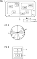
- the Figure 1 shows a schematic representation of an energy supply network 10 which is equipped with a large number of measuring devices PMU1 to PMU7.
- the measuring devices PMU1 to PMU7 are preferably pointer measuring devices that can detect electrical voltage indicators of conductor voltages and / or positive sequence voltages. Such measuring devices are also referred to in technical terms as "Phasor Measurement Units".
- the measuring devices PMU1 to PMU7 are connected to a monitoring device 20 and transmit their measured values to it.
- the measured values are preferably phase position values, which are identified by the reference symbols ⁇ 1 to ⁇ 7, and / or voltage vectors from all three phases, from which the associated positive sequence system component is determined and their respective phase position is used below as phase position value.
- the connection for the transmission of the phase position values ⁇ 1 to ⁇ 7 is for reasons of clarity in the Figure 1 not shown in detail.
- the Figure 2 shows the example of the measuring devices PMU1 to PMU7 according to FIG Figure 1 measured pointer measured values with the corresponding phase position values ⁇ 1 to ⁇ 7.
- FIG. 11 shows an exemplary embodiment for a monitoring device 20 which, in the arrangement according to FIG Figure 1 can be used to monitor the power supply network 10.
- the monitoring device 20 comprises a computer 21 and a memory 22.
- An island recognition program IP is stored in the memory 22 which, when executed by the computer 21, enables the computer 21 to operate the energy supply network 10 in accordance with Figure 1 to examine for possible island formation.
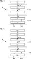
- FIG. 11 shows, in the form of a flow chart, an exemplary embodiment of an island recognition program IP that is generated by the monitoring device 20 according to FIG Figure 3 for monitoring the energy supply network 10 according to Figure 1 can be executed.
- the island detection program IP according to Figure 4 has a detection step 100 which is used to detect the data from the measuring devices PMU1 to PMU7 according to Figure 1 transmitted phase position values ⁇ 1 to ⁇ 7 is used.
- phase position values ⁇ 1 to ⁇ 7 acquired in acquisition step 100 arrive at a sorting procedure 110, which includes a presorting step 111 and a re-sorting procedure 112.
- the phase position values ⁇ 1 to ⁇ 7 are sorted according to size, forming a presorted phase position sequence VSR.
- the presorted phase position sequence VSR arrives at the re-sorting procedure 112, in which a re-sorting of the presorted phase position sequence takes place while forming a sorted phase position sequence SR.
- the alarm threshold value AS is 60 °.
- phase position sequence is rearranged by increasing the smallest phase position value (here -170 °) by 360 °.
- the increase by 360 ° now results in a phase position value of + 190 °, which is sorted accordingly in the phase position sequence.
- phase position sequence is rearranged again by increasing the phase position value ⁇ 2 by 360 ° and re-sorting it accordingly in the phase position sequence.
- a differentiation step 121 and a comparison step 122 are carried out in accordance with the sorted phase position sequence SR for each phase position value following a predetermined start phase value.
- the phase difference here is 46 °.
- step 122 it is checked whether the amount of the phase position difference exceeds or falls below the alarm threshold value AS.
- the next difference formation step 121 is carried out with the same reference phase value ⁇ 7.
- the phase position difference between the current reference phase value is now ⁇ 7 and the subsequent phase position value ⁇ 4 are formed and compared with the alarm threshold value AS.
- the difference here is 85 ° and exceeds the alarm threshold value AS. Because the alarm threshold value AS is exceeded, it is assumed that the phase position value ⁇ 4 with the two phase position values ⁇ 6 and ⁇ 7 is no longer synchronous (or sufficiently synchronous) and to a separate island within the power supply network 10 according to Figure 1 belongs.
- the phase position value ⁇ 4 is now set as the new reference phase value, and work continues with the subtraction step 121 for the next following phase position value ⁇ 5 using the now new reference phase value ⁇ 4.
- the difference between the phase position values ⁇ 5 and ⁇ 4 is subsequently formed, and in the subsequent comparison step 122 the determined difference becomes
- phase position difference between the phase position value ⁇ 3 and the reference phase value ⁇ 4 exceeds the alarm threshold value AS, so that it is now established that the phase position value ⁇ 3 belongs to a third island within the energy supply network 10.
- the phase position value ⁇ 3 is now set as the new reference phase value and the method is continued for the subsequent phase position value ⁇ 1.
- phase position value ⁇ 1 is assigned to the island of the phase position value ⁇ 3 and the method is continued with the reference phase value ⁇ 3.
- phase position difference from the current reference phase value ⁇ 3 is small enough that the phase position value ⁇ 2 is also assigned to the island with the phase position values ⁇ 1 and ⁇ 3.
- the analysis procedure 120 After the sorted phase position sequence SR has been processed, the analysis procedure 120 thus comes to the result that an island detection signal IS is to be generated, which indicates island formation within the energy supply network 10.
- the analysis procedure 120 generates an island data set IDS, which indicates that there are a total of three islands or three sub-networks within the energy supply network 10, each of which works synchronously (or sufficiently synchronously).
- the selection of the start phase value for the analysis procedure 120 is otherwise arbitrary; instead of the largest phase position value or the smallest phase position value, an average phase value can also be selected.
- FIG. 3 shows a further exemplary embodiment of an island recognition program IP which is generated by the computer 21 according to FIG Figure 1 can be used.
- a frequency and / or frequency change evaluation module 400 which is carried out before the execution of the acquisition step 100 and first carries out a preliminary check as to whether frequency values and / or frequency change values of the measuring devices PMU1 to PMU7 for asynchronicity or island formation within the energy supply network 10 according to Figure 1 indicate.
- the subsequent analysis of the phase position values of the measuring devices PMU1 to PMU7 is carried out only when it is determined in the course of the execution of the frequency and / or frequency change evaluation module 400 that islands are likely to have formed.
- the synchronous subnetworks identified by the frequency and / or frequency change evaluation module 400 are each individually further analyzed for islands within the respective subnetworks, as was done in connection with FIG Figure 4 has been explained.
- phase position values independently of the work result of the frequency and / or frequency change evaluation module 400, as was done in connection with FIG Figure 4 has been explained above. In this case, any island formation can be recognized even with very small frequency deviations.
Description
Die Erfindung bezieht sich auf ein Verfahren zum Überwachen eines elektrischen Energieversorgungsnetzes oder eines Teilnetzes des Energieversorgungsnetzes, insbesondere eines zuvor anhand eines anderen Verfahrens ermittelten Teilnetzes des Energieversorgungsnetzes, wobei an zumindest zwei Messstellen des Energieversorgungsnetzes oder Teilnetzes erfasste Messwerte ausgewertet werden.The invention relates to a method for monitoring an electrical energy supply network or a sub-network of the energy supply network, in particular a sub-network of the energy supply network previously determined using another method, with measured values recorded at at least two measuring points of the energy supply network or sub-network being evaluated.
Ein derartiges Verfahren ist aus der US-Patentschrift
Der Erfindung liegt die Aufgabe zugrunde, ein Verfahren zum Überwachen eines Netzes anzugeben, das besonders einfach zuverlässige Ergebnisse mit Blick auf eine Inselbildung liefert.The invention is based on the object of specifying a method for monitoring a network which provides reliable results with a view to island formation in a particularly simple manner.
Diese Aufgabe wird erfindungsgemäß durch ein Verfahren mit den Merkmalen gemäß Patentanspruch 1 sowie durch eine Überwachungseinrichtung gemäß den Merkmalen des Anspruchs 13 gelöst. Vorteilhafte Ausgestaltungen des erfindungsgemäßen Verfahrens sind in Unteransprüchen angegeben.According to the invention, this object is achieved by a method having the features according to patent claim 1 and by a monitoring device according to the features of
Danach ist erfindungsgemäß vorgesehen, dass als Messwerte Phasenlagenwerte ausgewertet oder mit den Messwerten ermittelte Phasenlagenwerte ausgewertet werden, anhand der Phasenlagenwerte geprüft wird, ob das Energieversorgungsnetz oder das Teilnetz synchron arbeitet, und im Falle einer anhand der Phasenlagenwerte erkannten Asynchronität ein Inselerkennungssignal erzeugt wird.According to the invention, it is then provided that the measured values Phase position values are evaluated or phase position values determined with the measured values are evaluated, based on the phase position values it is checked whether the power supply network or the sub-network is operating synchronously, and in the case of an asynchronicity detected on the basis of the phase position values, an island detection signal is generated.
Ein wesentlicher Vorteil des erfindungsgemäßen Verfahrens ist darin zu sehen, dass allein anhand von Phasenlagenwerten und damit sehr schnell eine zuverlässige Aussage über eine etwaige Asynchronität innerhalb eines Netzes oder Teilnetzes und eine etwaige Inselbildung getroffen werden kann. Auch kann in vorteilhafter Weise eine Inselbildung bei sehr geringen Frequenzabweichungen erkannt werden, die bei dem eingangs beschriebenen Verfahren auf der Basis von Frequenzwerten und Frequenzänderungswerten unter Umständen nicht immer erkannt wird.An essential advantage of the method according to the invention is that a reliable statement about any asynchrony within a network or sub-network and any island formation can be made based solely on phase position values and thus very quickly. Island formation can also be recognized in an advantageous manner in the case of very small frequency deviations, which in the method described at the beginning may not always be recognized on the basis of frequency values and frequency change values.
Als Messwerte werden vorzugsweise Phasenlagenwerte von Messzeigern, insbesondere Spannungszeigern, ausgewertet.Phase position values of measuring pointers, in particular voltage pointers, are preferably evaluated as measured values.
Besonders bevorzugt werden als Messwerte Phasenlagenwerte von Leiterspannungszeigern oder Mitsystemspannungszeigern ausgewertet.Phase position values of conductor voltage indicators or positive sequence voltage indicators are particularly preferably evaluated as measured values.
Im Falle einer anhand der Phasenlagenwerte erkannten Asynchronität werden vorzugsweise synchron arbeitende Inseln innerhalb des Energieversorgungsnetzes oder des jeweiligen Teilnetzes ermittelt.In the case of asynchronicity detected on the basis of the phase position values, islands that operate synchronously are preferably determined within the energy supply network or the respective sub-network.
Erfindungsgemäß ist außerdem vorgesehen, dass die Phasenlagenwerte unter Bildung einer sortierten Phasenlagenreihenfolge sortiert werden, ausgehend von dem größten oder kleinsten Phasenlagenwert - nachfolgend Startphasenwert genannt - der sortierten Phasenlagenreihenfolge die Differenz zu dem in der Phasenlagenreihenfolge nachfolgenden, also dem zweitgrößten oder zweitkleinsten, Phasenlagenwert ermittelt wird, das Inselerkennungssignal erzeugt wird, wenn die Phasenlagendifferenz zwischen dem Startphasenwert und dem nachfolgenden Phasenlagenwert betragsmäßig einen vorgegebenen Alarmschwellenwert überschreitet, und der Startphasenwert und der benachbarte Phasenlagenwert als synchron angesehen werden, wenn die Phasenlagendifferenz zwischen dem Startphasenwert und dem benachbarten Phasenlagenwert betragsmäßig den vorgegebenen Alarmschwellenwert unterschreitet.According to the invention, it is also provided that the phase position values are sorted by forming a sorted phase position sequence, starting from the largest or smallest phase position value - hereinafter referred to as the start phase value - the sorted phase position sequence, the difference to the phase position value following in the phase position sequence, i.e. the second largest or second smallest, is determined, the island detection signal is generated when the phase position difference between the start phase value and the subsequent phase position value exceeds a predetermined alarm threshold value exceeds, and the start phase value and the adjacent phase position value are considered to be synchronous if the phase position difference between the start phase value and the adjacent phase position value falls below the predetermined alarm threshold value in terms of amount.
Es kann in vorteilhafter Weise vorgesehen sein, dass die Phasenlagenwerte unter Bildung einer sortierten Phasenlagenreihenfolge sortiert werden und gemäß der sortierten Phasenlagenreihenfolge für jeden auf den Startphasenwert folgenden Phasenlagenwert jeweils ein Differenzbildungsschritt und ein Vergleichsschritt durchgeführt wird.It can be provided in an advantageous manner that the phase position values are sorted while forming a sorted phase position sequence and, according to the sorted phase position sequence, a differentiation step and a comparison step are carried out for each phase position value following the start phase value.
Bei der letztgenannten Ausführungsvariante ist es besonders vorteilhaft, wenn in dem Differenzbildungsschritt die Phasenlagendifferenz zwischen einem Referenzphasenwert, bei dem es sich um den Startphasenwert handelt, sofern er nicht in einem vorherigen Vergleichsschritt durch einen anderen Referenzphasenwert ersetzt worden ist, und dem jeweils folgenden Phasenlagenwert ermittelt wird.In the last-mentioned embodiment variant, it is particularly advantageous if in the difference formation step the phase position difference between a reference phase value, which is the starting phase value, unless it was replaced by another reference phase value in a previous comparison step, and the respective following phase position value is determined .
Bezüglich des Vergleichsschritts ist es besonders vorteilhaft, wenn in dem Vergleichsschritt die Phasenlagendifferenz mit dem Alarmschwellenwert verglichen wird, die bei dem Vergleich betrachteten Phasenlagenwerte als synchron angesehen werden und mit dem Differenzbildungsschritt für den nachfolgenden Phasenlagenwert in der Phasenlagenreihenfolge und demselben Referenzphasenwert fortgefahren wird, wenn die Phasenlagendifferenz betragsmäßig den Alarmschwellenwert unterschreitet, und der bei dem vorherigen Differenzbildungsschritt als folgender Phasenlagenwert herangezogene Phasenlagenwert einer neuen Insel zugeordnet und als neuer Referenzphasenwert festgelegt wird und mit dem Differenzbildungsschritt für den nachfolgenden Phasenlagenwert in der Phasenlagenreihenfolge und dem neu festgesetzten Referenzphasenwert fortgefahren wird, wenn die Phasenlagendifferenz betragsmäßig den Alarmschwellenwert überschreitet.With regard to the comparison step, it is particularly advantageous if, in the comparison step, the phase position difference is compared with the alarm threshold value, the phase position values considered in the comparison are viewed as synchronous and the difference formation step for the subsequent phase position value in the phase position sequence and the same reference phase value is continued if the phase position difference The amount falls below the alarm threshold value, and the phase position value used in the previous difference formation step as the following phase position value is assigned to a new island and specified as the new reference phase value and the difference formation step for the following phase position value in the phase position sequence and the newly established reference phase value is continued if the phase position difference is the absolute value Alarm threshold exceeded.
Das Sortieren der Phasenlagenwerte umfasst bei einer ersten besonders vorteilhaften Verfahrensvariante vorzugsweise folgende Sortierschritte:
- Vorsortieren der Phasenlagenwerte nach Größe unter Bildung einer vorsortierten Phasenlagenreihenfolge,
- Prüfen, ob die Zeigerwinkeldifferenz zwischen dem Zeigerwinkel des Messzeigers, der zu dem größten Phasenlagenwert gehört, und dem Zeigerwinkel des Messzeigers, der zu dem kleinsten Phasenlagenwert gehört, den Alarmschwellenwert über- oder unterschreitet,
- im Falle einer Unterschreitung des Alarmschwellenwerts die Phasenlagenreihenfolge umsortiert wird, indem der kleinste Phasenlagenwert um 360° erhöht wird, und
- im Falle einer Überschreitung des Alarmschwellenwerts die Phasenlagenreihenfolge unverändert bleibt und die vorsortierte Phasenlagenreihenfolge als sortierte Phasenlagenreihenfolge weiterverwendet wird.
- Pre-sorting the phase position values according to size with the formation of a pre-sorted phase position sequence,
- Check whether the pointer angle difference between the pointer angle of the measuring pointer belonging to the largest phase position value and the pointer angle of the measuring pointer belonging to the smallest phase position value exceeds or falls below the alarm threshold value,
- in the event that the alarm threshold value is not reached, the phase position sequence is rearranged by increasing the smallest phase position value by 360 °, and
- in the event that the alarm threshold is exceeded, the phase position sequence remains unchanged and the presorted phase position sequence continues to be used as the sorted phase position sequence.
Bei der letztgenannten Verfahrensvariante ist es vorteilhaft, wenn nachfolgend in weiteren Umsortierschritten jeweils geprüft wird, ob die Differenz zwischen dem - gemäß Fortschritt des Umsortierens - jeweils aktuell kleinsten Phasenlagenwert und dem vor dem letzten Umsortierschritt kleinsten Phasenlagenwert den Alarmschwellenwert überschreitet, im Falle einer Unterschreitung des Alarmschwellenwerts die umsortierte Phasenlagenreihenfolge nochmals umsortiert wird, indem der aktuell kleinste Phasenlagenwert um 360° erhöht wird, und das Umsortierverfahren mit dem nächsten Umsortierschritt fortgesetzt wird und im Falle einer Überschreitung des Alarmschwellenwerts das Umsortieren beendet wird und die bis dahin gebildete umsortierte Phasenlagenreihenfolge als sortierte Phasenlagenreihenfolge weiterverwendet wird.In the case of the last-mentioned variant of the method, it is advantageous if it is subsequently checked in further re-sorting steps whether the difference between the currently smallest phase position value and the phase position value that was the smallest before the last re-sorting step exceeds the alarm threshold value, if the value falls below the alarm threshold value the rearranged phase position sequence is re-sorted again by increasing the currently smallest phase position value by 360 °, and the re-sorting process is continued with the next re-sorting step and, if the alarm threshold is exceeded, the re-sorting is ended and the rearranged phase position sequence formed up to that point is used as the sorted phase position sequence .
Das Umsortieren erfolgt bei der obigen Verfahrensweise also anschaulich beschrieben durch ein Umsortieren "nach oben". Das Sortieren der Phasenlagenwerte umfasst bei einer zweiten besonders vorteilhaften Verfahrensvariante vorzugsweise folgende Sortierschritte:
- Vorsortieren der Phasenlagenwerte nach Größe unter Bildung einer vorsortierten Phasenlagenreihenfolge,
- Prüfen, ob die Zeigerwinkeldifferenz zwischen dem Zeigerwinkel eines Messzeigers, der zu dem größten Phasenlagenwert gehört, und dem Zeigerwinkel eines Messzeigers, der zu dem kleinsten Phasenlagenwert gehört, den Alarmschwellenwert über- oder unterschreitet,
- im Falle einer Unterschreitung des Alarmschwellenwerts die Phasenlagenreihenfolge umsortiert wird, indem der größte Phasenlagenwert um 360° reduziert wird, und
- im Falle einer Überschreitung des Alarmschwellenwerts die Phasenlagenreihenfolge unverändert bleibt und die vorsortierte Phasenlagenreihenfolge als sortierte Phasenlagenreihenfolge weiterverwendet wird.
- Pre-sorting the phase position values according to size with the formation of a pre-sorted phase position sequence,
- Check whether the pointer angle difference between the pointer angle of a measuring pointer belonging to the largest phase position value and the pointer angle of a measuring pointer belonging to the smallest phase position value exceeds or falls below the alarm threshold value,
- in the event that the alarm threshold value is not reached, the phase position sequence is rearranged by reducing the largest phase position value by 360 °, and
- in the event that the alarm threshold is exceeded, the phase position sequence remains unchanged and the presorted phase position sequence continues to be used as the sorted phase position sequence.
Bei der letztgenannten Verfahrensvariante ist es vorteilhaft, wenn nachfolgend in weiteren Umsortierschritten jeweils geprüft wird, ob die Differenz zwischen dem - gemäß Fortschritt des Umsortierens - jeweils aktuell größten Phasenlagenwert und dem vor dem letzten Umsortierschritt größten Phasenlagenwert den Alarmschwellenwert überschreitet, im Falle einer Unterschreitung des Alarmschwellenwerts die umsortierte Phasenlagenreihenfolge nochmals umsortiert wird, indem der aktuell größte Phasenlagenwert um 360° reduziert wird, und das Umsortierverfahren mit dem nächsten Umsortierschritt fortgesetzt wird und im Falle einer Überschreitung des Alarmschwellenwerts das Umsortieren beendet wird und die bis dahin gebildete umsortierte Phasenlagenreihenfolge als sortierte Phasenlagenreihenfolge weiterverwendet wird.In the case of the last-mentioned variant of the method, it is advantageous if it is subsequently checked in further re-sorting steps whether the difference between the currently largest phase position value - according to the progress of the re-sorting - and the phase position value that was largest prior to the last re-sorting step exceeds the alarm threshold value, if the value falls below the alarm threshold value the rearranged phase position sequence is rearranged again by reducing the currently largest phase position value by 360 °, and the re-sorting process is continued with the next re-sorting step and, if the alarm threshold is exceeded, the re-sorting is ended and the rearranged phase position sequence formed up to that point is used as the sorted phase position sequence .
Das Umsortieren erfolgt bei der zweiten besonders vorteilhaften Verfahrensvariante also anschaulich beschrieben durch ein Umsortieren "nach unten".In the second particularly advantageous variant of the method, the re-sorting takes place, thus clearly described, by a re-sorting “downwards”.
Die Phasenlagenwerte werden vorzugsweise nach Größe unter Bildung einer Phasenlagenreihenfolge ausgehend von dem kleinsten Phasenlagenwert in aufsteigender Reihenfolge sortiert.The phase position values are preferably sorted according to size, forming a phase position sequence starting from the smallest phase position value in ascending order.
Die Reihenfolgenrichtung, in der der jeweils nächste benachbarte Phasenlagenwert herangezogen wird, ist vorzugsweise die aufsteigende Richtung.The sequence direction in which the next adjacent phase position value is used is preferably the ascending direction.
Auch wird es als vorteilhaft angesehen, wenn anhand von Frequenzwerten oder Frequenzänderungswerten geprüft wird, ob das Energieversorgungsnetz synchron arbeitet und im Falle einer Asynchronität des Energieversorgungsnetzes das Energieversorgungsnetz in Teilnetze aufgeteilt wird, und das oben beschriebene Verfahren für zumindest eines der Teilnetze des Energieversorgungsnetzes durchgeführt wird.It is also considered to be advantageous if, on the basis of frequency values or frequency change values, it is checked whether the energy supply network is working synchronously and, in the event of asynchronicity of the energy supply network, the energy supply network is divided into sub-networks, and the method described above is carried out for at least one of the sub-networks of the energy supply network.
Falls anhand von Frequenzwerten oder Frequenzänderungswerten keine Asynchronität des Energieversorgungsnetzes festgestellt wird, kann das oben beschriebene Verfahren für das gesamte Energieversorgungsnetz oder ein beliebig ausgewähltes Teilnetz durchgeführt werden.If no asynchronicity of the energy supply network is found on the basis of frequency values or frequency change values, the method described above can be carried out for the entire energy supply network or any selected sub-network.
Die Erfindung bezieht sich darüber hinaus auf eine Überwachungseinrichtung zum Überwachen eines elektrischen Energieversorgungsnetzes oder eines Teilnetzes des Energieversorgungsnetzes, wobei die Überwachungseinrichtung Messwerte zumindest zweier Messstellen des Energieversorgungsnetzes oder Teilnetzes heranzieht und gemäß den Merkmalen des Anspruchs 13 ausgebildet ist.The invention also relates to a monitoring device for monitoring an electrical energy supply network or a sub-network of the energy supply network, the monitoring device using measured values from at least two measuring points of the energy supply network or sub-network and being designed according to the features of
Bezüglich der Vorteile der erfindungsgemäßen Überwachungseinrichtung sei auf die obigen Ausführungen im Zusammenhang mit dem erfindungsgemäßen Verfahren verwiesen.With regard to the advantages of the monitoring device according to the invention, reference is made to the above statements in connection with the method according to the invention.
Die Erfindung wird nachfolgend anhand von Ausführungsbeispielen näher erläutert; dabei zeigen beispielhaft
- Figur 1
- in einer schematischen Darstellung ein Energieversorgungsnetz, das mit einer Überwachungseinrichtung zur Erkennung einer etwaigen Inselbildung innerhalb des Energieversorgungsnetzes ausgestattet ist,
- Figur 2
- beispielhaft elektrische Spannungszeiger, die von an das Energieversorgungsnetz gemäß
Figur 1 angeschlossenen Messgeräten gemessen werden, in der komplexen Ebene, - Figur 3
- ein Ausführungsbeispiel für eine Überwachungseinrichtung, die bei der Anordnung gemäß
Figur 1 eingesetzt werden kann, - Figur 4
- in Form eines Ablaufdiagramms ein Ausführungsbeispiel für ein Inselerkennungsprogramm, das für die Überwachungseinrichtung gemäß
Figur 3 zum Überwachen des Energieversorgungsnetzes gemäßFigur 1 geeignet ist, und - Figur 5
- in Form eines Ablaufdiagramms ein weiteres Ausführungsbeispiel für ein Inselerkennungsprogramm, das für die Überwachungseinrichtung gemäß
Figur 3 zum Überwachen des Energieversorgungsnetzes gemäßFigur 1 geeignet ist.
- Figure 1
- a schematic representation of an energy supply network that is equipped with a monitoring device for detecting any island formation within the energy supply network,
- Figure 2
- for example, electrical voltage indicators that are sent from to the power supply network according to
Figure 1 connected measuring devices are measured in the complex plane, - Figure 3
- an embodiment of a monitoring device, which in the arrangement according to
Figure 1 can be used, - Figure 4
- in the form of a flowchart an exemplary embodiment of an island detection program that is used for the monitoring device according to FIG
Figure 3 for monitoring the energy supply network according toFigure 1 is suitable, and - Figure 5
- in the form of a flowchart a further exemplary embodiment for an island recognition program that is used for the monitoring device according to FIG
Figure 3 for monitoring the energy supply network according toFigure 1 suitable is.
In den Figuren werden der Übersicht halber für identische oder vergleichbare Komponenten stets dieselben Bezugszeichen verwendet.For the sake of clarity, the same reference symbols are always used in the figures for identical or comparable components.
Die
Die Messgeräte PMU1 bis PMU7 sind an eine Überwachungseinrichtung 20 angeschlossen und übertragen an diese ihre Messwerte. Bei den Messwerten handelt es sich, wie weiter unten noch näher im Detail erläutert werden wird, vorzugsweise um Phasenlagenwerte, die mit den Bezugszeichen ϕ1 bis ϕ7 gekennzeichnet sind, und/oder um Spannungszeiger von allen drei Phasen, aus denen die zugehörige Mitsystemkomponente ermittelt und deren jeweilige Phasenlage nachfolgend als Phasenlagenwert verwendet wird. Die Verbindung zur Übertragung der Phasenlagenwerte ϕ1 bis ϕ7 ist aus Gründen der Übersicht in der
Die
Die
Die Überwachungseinrichtung 20 umfasst einen Rechner 21 und einen Speicher 22. In dem Speicher 22 ist ein Inselerkennungsprogramm IP abgespeichert, das bei Ausführung durch den Rechner 21 diesen befähigt, das Energieversorgungsnetz 10 gemäß
Die
Das Inselerkennungsprogramm IP gemäß
Die im Erfassungsschritt 100 erfassten Phasenlagenwerte ϕ1 bis ϕ7 können beispielsweise folgende Werte aufweisen:
Die im Erfassungsschritt 100 erfassten Phasenlagenwerte ϕ1 bis ϕ7 gelangen zu einer Sortierprozedur 110, die einen Vorsortierschritt 111 und eine Umsortierprozedur 112 umfasst.The phase position values ϕ1 to ϕ7 acquired in
Im Rahmen des Vorsortierschritts 111 werden die Phasenlagenwerte ϕ1 bis ϕ7 nach Größe unter Bildung einer vorsortierten Phasenlagenreihenfolge VSR sortiert. Die im Rahmen des Vorsortierens gebildete vorsortierte Phasenlagenreihenfolge VSR kann beispielsweise wie folgt aussehen:
Die vorsortierte Phasenlagenreihenfolge VSR gelangt zu der Umsortierprozedur 112, in der ein Umsortieren der vorsortierten Phasenlagenreihenfolge unter Bildung einer sortierten Phasenlagenreihenfolge SR erfolgt.The presorted phase position sequence VSR arrives at the
In einem ersten Schritt der Umsortierprozedur 112 wird geprüft, ob die Zeigerwinkeldifferenz zwischen dem Zeigerwinkel des Messzeigers, der zu dem größten Phasenlagenwert (hier ϕ3 = +170°) gehört, und dem Zeigerwinkel des Messzeigers, der zu dem kleinsten Phasenlagenwert (hier ϕ1 = -170°) gehört, einen Alarmschwellenwert AS über- oder unterschreitet.In a first step of the
Nachfolgend wird beispielhaft davon ausgegangen, dass der Alarmschwellenwert AS 60° beträgt.In the following it is assumed as an example that the alarm threshold value AS is 60 °.
Im Falle einer Unterschreitung des Alarmschwellenwerts AS - wie es hier der Fall ist, weil die Zeigerwinkeldifferenz Δϕ lediglich 20° beträgt - wird die Phasenlagenreihenfolge umsortiert, indem der kleinste Phasenlagenwert (hier -170°) um 360° erhöht wird. Durch die Erhöhung um 360° ergibt sich nun ein Phasenlagenwert von +190°, der in der Phasenlagenreihenfolge entsprechend einsortiert wird. Es ergibt sich nun folgende Phasenlagenreihenfolge:
Durch das Umsortieren des Phasenlagenwerts ϕ1 ist nunmehr der Phasenlagenwert ϕ2 = -140° der kleinste Phasenlagenwert der Phasenlagenreihenfolge. In weiteren Umsortierschritten wird nun jeweils geprüft, ob die Differenz zwischen dem - gemäß Fortschritt des Umsortierens - jeweils aktuell kleinsten Phasenlagenwert und dem vor dem letzten Umsortierschritt kleinsten Phasenlagenwert den Alarmschwellenwert AS überschreitet oder nicht.By rearranging the phase position value ϕ1, the phase position value ϕ2 = -140 ° is now the smallest phase position value in the phase position sequence. In further re-sorting steps it is now checked whether the difference between the - accordingly Progress of the re-sorting - in each case the currently smallest phase position value and the phase position value that was smallest before the last re-sorting step exceeds the alarm threshold value AS or not.
Da - wie erwähnt - nun der Phasenlagenwert ϕ2 = -140° der kleinste Phasenlagenwert der Phasenlagenreihenfolge ist, wird demgemäß geprüft, ob die Differenz zwischen dem Phasenlagenwert ϕ2 und dem Phasenlagenwert ϕ1 = -170° (vor dem Erhöhen um 360°) kleiner als der Alarmschwellenwert AS ist.Since - as mentioned - the phase position value ϕ2 = -140 ° is the smallest phase position value of the phase position sequence, a check is made accordingly whether the difference between the phase position value ϕ2 and the phase position value ϕ1 = -170 ° (before increasing by 360 °) is smaller than the Alarm threshold AS is.
Da hier gilt: ![]()
![]()
Aufgrund des letzten Umsortierschritts ist nunmehr der Phasenlagenwert ϕ7 = -75° der kleinste Phasenlagenwert. Da dessen Differenz zu dem zuvor umsortierten Phasenlagenwert ϕ2 (vor dem Erhöhen -140°) 65° beträgt und größer als der Alarmschwellenwert AS ist, wird das Umsortieren bzw. die Umsortierprozedur 112 beendet und folgende sortierte Phasenlagenreihenfolge SR an eine nachgeordnete Analyseprozedur 120 übermittelt:
Im Rahmen der Analyseprozedur 120 werden gemäß der sortierten Phasenlagenreihenfolge SR für jeden auf einen vorgegebenen Startphasenwert folgenden Phasenlagenwert jeweils ein Differenzbildungsschritt 121 und ein Vergleichsschritt 122 durchgeführt.In the context of the
Nachfolgend wird beispielhaft davon ausgegangen, dass der kleinste Phasenlagenwert der sortierten Phasenlagenreihenfolge SR, hier also der Phasenlagenwert ϕ7 = -75° den Startphasenwert und damit den ersten Referenzphasenwert bildet.In the following, it is assumed by way of example that the smallest phase position value of the sorted phase position sequence SR, here the phase position value ϕ7 = -75 °, forms the start phase value and thus the first reference phase value.
In dem Differenzbildungsschritt 121 wird zunächst die Phasenlagendifferenz zwischen dem Startphasenwert ϕ7 und dem nächst größten Phasenlagenwert ϕ6 = -29° ermittelt. Die Phasenlagendifferenz beträgt hier 46°.In the
In dem nachfolgenden Vergleichsschritt 122 wird geprüft, ob die Phasenlagendifferenz betragsmäßig den Alarmschwellenwert AS über- oder unterschreitet.In the
Da im vorliegenden Fall die Differenz zwischen den beiden Phasenlagenwerten ϕ6 und ϕ7 kleiner als der Alarmschwellenwert AS ist, wird davon ausgegangen, dass die beiden Phasenlagenwerte ϕ6 und ϕ7 synchron bzw. gemäß dem in Form des Alarmschwellenwerts AS vorgegebenen Synchronitätskriterium hinreichend synchron sind. Demgemäß wird mit demselben Referenzphasenwert ϕ7 der nächste Differenzbildungsschritt 121 durchgeführt.Since in the present case the difference between the two phase position values ϕ6 and ϕ7 is smaller than the alarm threshold value AS, it is assumed that the two phase position values ϕ6 and ϕ7 are synchronous or sufficiently synchronous according to the synchronicity criterion specified in the form of the alarm threshold value AS. Accordingly, the next
In dem nächsten Differenzbildungsschritt 121 wird nun die Phasenlagendifferenz zwischen dem aktuellen Referenzphasenwert ϕ7 und dem nachfolgenden Phasenlagenwert ϕ4 gebildet und mit dem Alarmschwellenwert AS verglichen. Die Differenz beträgt hier 85° und überschreitet den Alarmschwellenwert AS. Aufgrund der Überschreitung des Alarmschwellenwerts AS wird davon ausgegangen, dass der Phasenlagenwert ϕ4 mit den beiden Phasenlagenwerten ϕ6 und ϕ7 nicht mehr synchron (bzw. hinreichend synchron) ist und zu einer eigenen Insel innerhalb des Energieversorgungsnetzes 10 gemäß
In dem Differenzbildungsschritt 121 wird nachfolgend die Differenz zwischen den Phasenlagenwerten ϕ5 und ϕ4 gebildet, und in dem nachfolgenden Vergleichsschritt 122 wird die ermittelte Differenz |ϕ5-ϕ4| betragsmäßig mit dem Alarmschwellenwert AS verglichen. Dabei wird festgestellt, dass die Phasenlagendifferenz kleiner als der Alarmschwellenwert ist, ϕ4 und ϕ5 synchron (bzw. hinreichend synchron) sind und zu derselben Insel gehören, so dass nachfolgend nun der Phasenlagenwert ϕ3 untersucht werden kann, wobei es bei dem zuvor herangezogenen Referenzphasenwert ϕ4 bleibt.In the
Die Phasenlagendifferenz zwischen dem Phasenlagenwert ϕ3 und dem Referenzphasenwert ϕ4 überschreitet den Alarmschwellenwert AS, so dass nun festgestellt wird, dass der Phasenlagenwert ϕ3 zu einer dritten Insel innerhalb des Energieversorgungsnetzes 10 gehört. Der Phasenlagenwert ϕ3 wird nun als neuer Referenzphasenwert festgelegt und das Verfahren wird für den nachfolgenden Phasenlagenwert ϕ1 fortgesetzt.The phase position difference between the phase position value ϕ3 and the reference phase value ϕ4 exceeds the alarm threshold value AS, so that it is now established that the phase position value ϕ3 belongs to a third island within the
Da die Phasenlagendifferenz zwischen ϕ1 und ϕ3 lediglich 20° beträgt, wird der Phasenlagenwert ϕ1 zur Insel des Phasenlagenwerts ϕ3 zugeordnet wird und das Verfahren wird mit dem Referenzphasenwert ϕ3 fortgesetzt.Since the phase position difference between ϕ1 and ϕ3 is only 20 °, the phase position value ϕ1 is assigned to the island of the phase position value ϕ3 and the method is continued with the reference phase value ϕ3.
Auch bei dem letzten Phasenlagenwert ϕ2 ist die Phasenlagendifferenz zum aktuellen Referenzphasenwert ϕ3 klein genug, so dass auch der Phasenlagenwert ϕ2 der Insel mit den Phasenlagenwerten ϕ1 und ϕ3 zugeordnet wird.Even with the last phase position value ϕ2, the phase position difference from the current reference phase value ϕ3 is small enough that the phase position value ϕ2 is also assigned to the island with the phase position values ϕ1 and ϕ3.
Die Analyseprozedur 120 kommt nach Abarbeitung der sortierten Phasenlagenreihenfolge SR somit zu dem Ergebnis, dass ein Inselerkennungssignal IS zu erzeugen ist, das eine Inselbildung innerhalb des Energieversorgungsnetzes 10 anzeigt.After the sorted phase position sequence SR has been processed, the
Darüber hinaus erzeugt die Analyseprozedur 120 einen Inseldatensatz IDS, der anzeigt, dass es insgesamt drei Inseln bzw. drei Teilnetze innerhalb des Energieversorgungsnetzes 10 gibt, die jeweils für sich synchron (bzw. hinreichend synchron) arbeiten.In addition, the
Die Messgeräte PMU1 bis PMU7 werden dabei folgenden Inseln bzw. Teilnetzen zugeordnet (siehe
- Insel I1: PMU7 und PMU6
- Insel I2: PMU4 und PMU5
- Insel I3: PMU3, PMU1 und PMU2.
- Island I1: PMU7 and PMU6
- Island I2: PMU4 and PMU5
- Island I3: PMU3, PMU1 and PMU2.
Die in dem Inseldatensatz IDS festgelegte Zuordnung der Messgeräte PMU1 bis PMU7 zu Inseln ist abhängig von dem Startphasenwert, mit dem die Analyseprozedur 120 begonnen wird. Bei dem obigen Ausführungsbeispiel wurde von dem Phasenlagenwert ϕ7 als Startphasenwert ausgegangen. Würde alternativ als Startphasenwert der größte Phasenlagenwert ϕ2 der sortierten Phasenlagenreihenfolge SR ausgewählt werden, so ergäbe sich folgende Zuordnung der Messgeräte PMU1 bis PMU7:
- Insel I1: PMU2, PMU1 und PMU3.
- Insel I2: PMU5, PMU4 und PMU6
- Insel I3: PMU7
- Island I1: PMU2, PMU1 and PMU3.
- Island I2: PMU5, PMU4 and PMU6
- Island I3: PMU7
Es lässt sich erkennen, dass auch im Falle dieses Startphasenwerts drei Inseln erkannt werden.It can be seen that three islands are also recognized in the case of this start phase value.
Die Auswahl des Startphasenwerts für die Analyseprozedur 120 ist im Übrigen beliebig, es kann statt des größten Phasenlagenwerts oder des kleinsten Phasenlagenwerts auch ein mittlerer Phasenwert ausgewählt werden.The selection of the start phase value for the
Die
Im Unterschied zu dem Ausführungsbeispiel gemäß
Vorteilhaft ist es, wenn die nachfolgende Analyse der Phasenlagenwerte der Messgeräte PMU1 bis PMU7 ausschließlich dann durchgeführt wird, wenn im Rahmen der Ausführung des Frequenz- und/oder Frequenzänderungsauswertmoduls 400 festgestellt wird, dass voraussichtlich eine Inselbildung erfolgt ist. In diesem Falle werden vorzugsweise die von dem Frequenz- und/oder Frequenzänderungsauswertmodul 400 identifizierten synchronen Teilnetze jeweils individuell für sich weiter auf Inseln innerhalb der jeweiligen Teilnetze analysiert, wie dies im Zusammenhang mit der
Alternativ ist es möglich, unabhängig von dem Arbeitsergebnis des Frequenz- und/oder Frequenzänderungsauswertmoduls 400 die Überprüfung der Phasenlagenwerte durchzuführen, wie dies im Zusammenhang mit der
Bei den Ausführungsbeispielen gemäß den
Obwohl die Erfindung im Detail durch bevorzugte Ausführungsbeispiele näher illustriert und beschrieben wurde, so ist die Erfindung nicht durch die offenbarten Beispiele eingeschränkt und andere Variationen können vom Fachmann hieraus abgeleitet werden.Although the invention has been illustrated and described in more detail by means of preferred exemplary embodiments, the invention is not restricted by the disclosed examples and other variations can be derived therefrom by the person skilled in the art.
- 1010
- EnergieversorgungsnetzEnergy supply network
- 2020th
- ÜberwachungseinrichtungMonitoring device
- 2121st
- Rechnercomputer
- 2222nd
- SpeicherStorage
- 100100
- ErfassungsschrittAcquisition step
- 110110
- SortierprozedurSorting procedure
- 111111
- VorsortierschrittPre-sorting step
- 112112
- UmsortierprozedurRe-sorting procedure
- 120120
- AnalyseprozedurAnalysis procedure
- 121121
- DifferenzbildungsschrittDifference formation step
- 122122
- VergleichsschrittComparison step
- 400400
- Frequenz- und/oder FrequenzänderungsauswertmodulFrequency and / or frequency change evaluation module
- ASAS
- AlarmschwellenwertAlarm threshold
- IDSIDS
- InseldatensatzIsland record
- I1-I3I1-I3
- synchrone Inselnsynchronous islands
- IPIP
- InselerkennungsprogrammIsland detection program
- PMU1-PMU7PMU1-PMU7
- MessgeräteMeasuring device
- SRSR
- sortierte Phasenlagenreihenfolgesorted phase sequence
- VSRVSR
- vorsortierte Phasenlagenreihenfolgepre-sorted phase position sequence
- ϕ1-ϕ7ϕ1-ϕ7
- PhasenlagenwertePhase position values
Claims (13)
- Method for monitoring an electrical energy supply network (10) or a subnetwork of the energy supply network (10), wherein measurement values detected at at least two measurement points of the energy supply network (10) or subnetwork are evaluated, wherein- phase angle values are evaluated as measurement values or phase angle values determined using the measurement values are evaluated,- a check is carried out based on the phase angle values to determine whether the energy supply network (10) or the subnetwork is operating synchronously, and,- in the event of an asynchronism identified based on the phase angle values, an island identification signal (IS) is generated,
characterized in that- the phase angle values are sorted so as to form a sorted phase angle order (SR),- proceeding from the largest or smallest phase angle value - subsequently referred to as starting phase value - of the sorted phase angle order (SR), a phase angle difference from the subsequent phase angle value in the phase angle order (SR), that is to say the second-largest or second-smallest phase angle value, is determined,- the island identification signal (IS) is generated when the phase angle difference between the starting phase value and the subsequent phase angle value exceeds a prescribed alarm threshold value in terms of magnitude, and- the starting phase value and the subsequent phase angle value are considered to be synchronous when the phase angle difference between the starting phase value and the subsequent phase angle value undershoots the prescribed alarm threshold value in terms of magnitude. - Method according to Claim 1,
characterized in that
phase angle values of measurement phasors, in particular voltage phasors, are evaluated as measurement values. - Method according to either of the preceding claims,
characterized in that
phase angle values of conductor voltage phasors or positive phase-sequence system voltage phasors are evaluated as measurement values. - Method according to one of the preceding claims,
characterized in that,
in the event of an asynchronism identified based on the phase angle values, synchronously operating islands within the energy supply network (10) or the respective subnetwork are determined. - Method according to one of the preceding claims,
characterized in that
a difference formation step and a comparison step are carried out in each case for each phase angle value following the starting phase value according to the sorted phase angle order (SR) . - Method according to Claim 5,
characterized in that,- in the difference formation step, the phase angle difference between a reference phase value, which is the starting phase value provided it has not been replaced by another reference phase value in a preceding comparison step, and the respectively following phase angle value is determined, and,- in the comparison step,- the phase angle difference is compared with the alarm threshold value,- the phase angle values observed during the comparison are considered to be synchronous and the method proceeds with the difference formation step for the subsequent phase angle value in the phase angle order (SR) and the same reference phase value when the phase angle difference undershoots the alarm threshold value in terms of magnitude, and- the phase angle value used as the following phase angle value in the preceding difference formation step is assigned to a new island and is stipulated as a new reference phase value and the method proceeds with the difference formation step for the subsequent phase angle value in the phase angle order (SR) and the newly set reference phase value when the phase angle difference exceeds the alarm threshold value in terms of magnitude. - Method according to one of the preceding claims,
characterized in that
the sorting of the phase angle values comprises the following sorting steps:- presorting the phase angle values according to size so as to form a presorted phase angle order (VSR),- checking to determine whether the phasor angle difference between the phasor angle of the measurement phasor belonging to the largest phase angle value and the phasor angle of the measurement phasor belonging to the smallest phase angle value exceeds or undershoots the alarm threshold value,- in the event of the alarm threshold value being undershot, the phase angle order is resorted by virtue of the smallest phase angle value being increased by 360°, and- in the event of the alarm threshold value being exceeded, the phase angle order remains unchanged and the presorted phase angle order (VSR) continues to be used as the sorted phase angle order (SR). - Method according to Claim 7,
characterized in that,- in the event of successful resorting, a check is subsequently carried out in each further resorting step to determine whether the difference between the - according to the advancement of the resorting - respectively currently smallest phase angle value and the smallest phase angle value before the last resorting step exceeds the alarm threshold value,- in the event of the alarm threshold value being undershot, the resorted phase angle order is resorted again by virtue of the currently smallest phase angle value being increased by 360°, and the resorting method is continued with the next resorting step and- in the event of the alarm threshold value being exceeded, the resorting is ended and the resorted phase angle order formed until this point continues to be used as the sorted phase angle order (SR). - Method according to one of preceding Claims 1 to 6,
characterized in that
the sorting of the phase angle values comprises the following sorting steps:- presorting the phase angle values according to size so as to form a presorted phase angle order (VSR),- checking to determine whether the phasor angle difference between the phasor angle of a measurement phasor belonging to the largest phase angle value and the phasor angle of a measurement phasor belonging to the smallest phase angle value exceeds or undershoots the alarm threshold value,- in the event of the alarm threshold value being undershot, the phase angle order is resorted by virtue of the largest phase angle value being reduced by 360°, and- in the event of the alarm threshold value being exceeded, the phase angle order remains unchanged and the presorted phase angle order (VSR) continues to be used as the sorted phase angle order (SR). - Method according to Claim 9,
characterized in that,- in the event of successful resorting, a check is subsequently carried out in each further resorting step to determine whether the difference between the - according to the advancement of the resorting - respectively currently largest phase angle value and the largest phase angle value before the last resorting step exceeds the alarm threshold value,- in the event of the alarm threshold value being undershot, the resorted phase angle order is resorted again by virtue of the currently largest phase angle value being reduced by 360° and the resorting method is continued with the next resorting step and- in the event of the alarm threshold value being exceeded, the resorting is ended and the resorted phase angle order formed until this point continues to be used as the sorted phase angle order (SR). - Method according to one of the preceding claims,
characterized in that- the phase angle values are sorted according to size so as to form a phase angle order (SR) proceeding from the smallest phase angle value in ascending order and/or- the order direction in which the respectively next adjacent phase angle value is used is the ascending direction. - Method according to one of the preceding claims,
characterized in that- a check is carried out based on frequency values or frequency change values to determine whether the energy supply network (10) is operating synchronously and, in the event of an asynchronism of the energy supply network (10), the energy supply network is divided into subnetworks, and- the method according to one of the preceding claims is carried out for at least one of the subnetworks of the energy supply network (10). - Monitoring device for monitoring an electrical energy supply network (10) or a subnetwork of the energy supply network (10), wherein the monitoring device uses measurement values of at least two measurement points of the energy supply network (10) or subnetwork, wherein
the monitoring device is designed in such a way that it evaluates phase angle values as measurement values or determines phase angle values using the measurement values itself, checks based on the phase angle values whether the energy supply network (10) or the subnetwork is operating synchronously, and, in the event of an asynchronism identified based on the phase angle values, generates an island identification signal (IS),
characterized in that
the monitoring device is designed in such a way that- the phase angle values are sorted so as to form a sorted phase angle order (SR),- proceeding from the largest or smallest phase angle value - subsequently referred to as starting phase value - of the sorted phase angle order (SR), a phase angle difference from the subsequent phase angle value in the phase angle order (SR), that is to say the second-largest or second-smallest phase angle value, is determined,- the island identification signal (IS) is generated when the phase angle difference between the starting phase value and the subsequent phase angle value exceeds a prescribed alarm threshold value in terms of magnitude, and- the starting phase value and the subsequent phase angle value are considered to be synchronous when the phase angle difference between the starting phase value and the subsequent phase angle value undershoots the prescribed alarm threshold value in terms of magnitude.
Priority Applications (4)
| Application Number | Priority Date | Filing Date | Title |
|---|---|---|---|
| PL18164941T PL3547481T3 (en) | 2018-03-29 | 2018-03-29 | Method for monitoring an electrical grid |
| EP18164941.9A EP3547481B1 (en) | 2018-03-29 | 2018-03-29 | Method for monitoring an electrical grid |
| ES18164941T ES2863376T3 (en) | 2018-03-29 | 2018-03-29 | Procedure for monitoring an electrical network |
| US16/369,230 US11002775B2 (en) | 2018-03-29 | 2019-03-29 | Method for monitoring an electrical network |
Applications Claiming Priority (1)
| Application Number | Priority Date | Filing Date | Title |
|---|---|---|---|
| EP18164941.9A EP3547481B1 (en) | 2018-03-29 | 2018-03-29 | Method for monitoring an electrical grid |
Publications (2)
| Publication Number | Publication Date |
|---|---|
| EP3547481A1 EP3547481A1 (en) | 2019-10-02 |
| EP3547481B1 true EP3547481B1 (en) | 2021-01-13 |
Family
ID=61837685
Family Applications (1)
| Application Number | Title | Priority Date | Filing Date |
|---|---|---|---|
| EP18164941.9A Active EP3547481B1 (en) | 2018-03-29 | 2018-03-29 | Method for monitoring an electrical grid |
Country Status (4)
| Country | Link |
|---|---|
| US (1) | US11002775B2 (en) |
| EP (1) | EP3547481B1 (en) |
| ES (1) | ES2863376T3 (en) |
| PL (1) | PL3547481T3 (en) |
Families Citing this family (2)
| Publication number | Priority date | Publication date | Assignee | Title |
|---|---|---|---|---|
| DE102019133405A1 (en) * | 2019-12-06 | 2021-06-10 | Sma Solar Technology Ag | Method and arrangement for determining a load flow map within an AC power supply network |
| US10942204B1 (en) * | 2020-10-27 | 2021-03-09 | North China Electric Power University | Taylor weighted least squares method for estimating synchrophasor |
Family Cites Families (11)
| Publication number | Priority date | Publication date | Assignee | Title |
|---|---|---|---|---|
| JP3029185B2 (en) * | 1994-04-12 | 2000-04-04 | キヤノン株式会社 | Islanding prevention device, distributed power generation device and power generation system using the same |
| US6429546B1 (en) * | 1998-11-20 | 2002-08-06 | Georgia Tech Research Corporation | Systems and methods for preventing islanding of grid-connected electrical power systems |
| US9077208B2 (en) * | 2011-12-30 | 2015-07-07 | Schneider Electric USA, Inc. | Method of detecting instability in islanded electrical systems |
| US9293949B2 (en) * | 2012-02-06 | 2016-03-22 | Montana Tech Of The University Of Montana | Electric power grid signal processing methods, oscillatory mode estimation methods and mode shape estimation methods |
| WO2013127447A1 (en) | 2012-02-29 | 2013-09-06 | Siemens Aktiengesellschaft | Monitoring an electrical power supply network |
| US9124095B1 (en) * | 2013-02-15 | 2015-09-01 | Ideal Power Inc. | Islanding detection in power converters |
| US9331487B2 (en) * | 2013-03-14 | 2016-05-03 | Rockwell Automation Technologies, Inc. | Method and apparatus for islanding detection for grid tie converters |
| EP2806280A1 (en) * | 2013-05-21 | 2014-11-26 | ABB Research Ltd. | Detecting electrical islands using wide-area measurements |
| US9520819B2 (en) * | 2014-02-28 | 2016-12-13 | General Electric Company | System and method for controlling a power generation system based on a detected islanding event |
| US9997920B2 (en) * | 2014-06-11 | 2018-06-12 | Sinewatts, Inc. | System and method for islanding detection and prevention in distributed generation |
| US10833507B2 (en) * | 2016-11-29 | 2020-11-10 | Schweitzer Engineering Laboratories, Inc. | Island detection and control of a microgrid |
-
2018
- 2018-03-29 EP EP18164941.9A patent/EP3547481B1/en active Active
- 2018-03-29 ES ES18164941T patent/ES2863376T3/en active Active
- 2018-03-29 PL PL18164941T patent/PL3547481T3/en unknown
-
2019
- 2019-03-29 US US16/369,230 patent/US11002775B2/en active Active
Non-Patent Citations (1)
| Title |
|---|
| None * |
Also Published As
| Publication number | Publication date |
|---|---|
| EP3547481A1 (en) | 2019-10-02 |
| US20190302158A1 (en) | 2019-10-03 |
| PL3547481T3 (en) | 2021-07-12 |
| US11002775B2 (en) | 2021-05-11 |
| ES2863376T3 (en) | 2021-10-11 |
Similar Documents
| Publication | Publication Date | Title |
|---|---|---|
| EP3379273B1 (en) | Method, device and system for determining the location a fault on a line of an electrical energy supply network | |
| DE602005005516T2 (en) | METHOD AND DEVICE FOR DETECTING ELECTRIC ARC PHENOMENON ON AT LEAST ONE ELECTRICAL CABLE | |
| EP2845286B1 (en) | Fault detection in energy supply networks | |
| DE4333257A1 (en) | Method of obtaining an error flag signal | |
| DE112007000473T5 (en) | Current differential relay device, signal processing method therefor and power transmission line protection system | |
| EP0721685B1 (en) | Method of generating a signal indicating the direction of a short-circuit | |
| EP3547481B1 (en) | Method for monitoring an electrical grid | |
| EP0025035B1 (en) | Process for determining and evaluating faults in wires | |
| EP2293089A1 (en) | String malfunction monitoring | |
| DE102016113624A1 (en) | Motor drive with function to detect circuit abnormalities due to intrusion of foreign matter before a significant abnormality occurs | |
| EP2143185A1 (en) | Method and device for capturing a fault in an electrical supply grid | |
| EP3955012A1 (en) | Method and device for determining the location of a fault on a line of an electrical energy supply network | |
| DE102018208118A1 (en) | Method and apparatus for authenticating a message transmitted over a bus | |
| EP2903112B1 (en) | Method for identifying arcing faults and circuit breaker | |
| EP3108554B1 (en) | Differential protection method and differential protection device | |
| EP0143224A2 (en) | Method of recognizing the failure of one or more transmission channels in a redundant optical transmission system | |
| WO1997020219A2 (en) | Process for producing signals identifying faulty loops in a polyphase electrical power supply network | |
| EP0917979A1 (en) | Method for monitoring the interfering current and the state of railway vehicles | |
| DE102017129168A1 (en) | Spectrum classification method, classification method and receiving device | |
| DE102021112016B3 (en) | Method and device for determining a ground fault direction | |
| EP3300201A1 (en) | Method and device for monitoring an energy transmission device | |
| DE102021128355A1 (en) | Inverter system with motor insulation test function | |
| EP1341284B1 (en) | Plausibility check for voltage transformers in power distribution substations | |
| DE102018212845B3 (en) | A diagnostic method and apparatus for verifying operability of an electromechanical load, and a computer program product and a vehicle | |
| DE102018113627B4 (en) | Method and device for fault diagnosis in an electrical network having a ring structure, and computer program product |
Legal Events
| Date | Code | Title | Description |
|---|---|---|---|
| PUAI | Public reference made under article 153(3) epc to a published international application that has entered the european phase |
Free format text: ORIGINAL CODE: 0009012 |
|
| STAA | Information on the status of an ep patent application or granted ep patent |
Free format text: STATUS: THE APPLICATION HAS BEEN PUBLISHED |
|
| AK | Designated contracting states |
Kind code of ref document: A1 Designated state(s): AL AT BE BG CH CY CZ DE DK EE ES FI FR GB GR HR HU IE IS IT LI LT LU LV MC MK MT NL NO PL PT RO RS SE SI SK SM TR |
|
| AX | Request for extension of the european patent |
Extension state: BA ME |
|
| STAA | Information on the status of an ep patent application or granted ep patent |
Free format text: STATUS: REQUEST FOR EXAMINATION WAS MADE |
|
| 17P | Request for examination filed |
Effective date: 20200330 |
|
| RBV | Designated contracting states (corrected) |
Designated state(s): AL AT BE BG CH CY CZ DE DK EE ES FI FR GB GR HR HU IE IS IT LI LT LU LV MC MK MT NL NO PL PT RO RS SE SI SK SM TR |
|
| GRAP | Despatch of communication of intention to grant a patent |
Free format text: ORIGINAL CODE: EPIDOSNIGR1 |
|
| STAA | Information on the status of an ep patent application or granted ep patent |
Free format text: STATUS: GRANT OF PATENT IS INTENDED |
|
| INTG | Intention to grant announced |
Effective date: 20200910 |
|
| GRAS | Grant fee paid |
Free format text: ORIGINAL CODE: EPIDOSNIGR3 |
|
| GRAA | (expected) grant |
Free format text: ORIGINAL CODE: 0009210 |
|
| STAA | Information on the status of an ep patent application or granted ep patent |
Free format text: STATUS: THE PATENT HAS BEEN GRANTED |
|
| AK | Designated contracting states |
Kind code of ref document: B1 Designated state(s): AL AT BE BG CH CY CZ DE DK EE ES FI FR GB GR HR HU IE IS IT LI LT LU LV MC MK MT NL NO PL PT RO RS SE SI SK SM TR |
|
| REG | Reference to a national code |
Ref country code: GB Ref legal event code: FG4D Free format text: NOT ENGLISH |
|
| REG | Reference to a national code |
Ref country code: CH Ref legal event code: EP |
|
| REG | Reference to a national code |
Ref country code: DE Ref legal event code: R096 Ref document number: 502018003621 Country of ref document: DE |
|
| REG | Reference to a national code |
Ref country code: IE Ref legal event code: FG4D Free format text: LANGUAGE OF EP DOCUMENT: GERMAN |
|
| REG | Reference to a national code |
Ref country code: AT Ref legal event code: REF Ref document number: 1355267 Country of ref document: AT Kind code of ref document: T Effective date: 20210215 |
|
| REG | Reference to a national code |
Ref country code: NL Ref legal event code: FP |
|
| REG | Reference to a national code |
Ref country code: LT Ref legal event code: MG9D |
|
| PG25 | Lapsed in a contracting state [announced via postgrant information from national office to epo] |
Ref country code: BG Free format text: LAPSE BECAUSE OF FAILURE TO SUBMIT A TRANSLATION OF THE DESCRIPTION OR TO PAY THE FEE WITHIN THE PRESCRIBED TIME-LIMIT Effective date: 20210413 Ref country code: GR Free format text: LAPSE BECAUSE OF FAILURE TO SUBMIT A TRANSLATION OF THE DESCRIPTION OR TO PAY THE FEE WITHIN THE PRESCRIBED TIME-LIMIT Effective date: 20210414 Ref country code: HR Free format text: LAPSE BECAUSE OF FAILURE TO SUBMIT A TRANSLATION OF THE DESCRIPTION OR TO PAY THE FEE WITHIN THE PRESCRIBED TIME-LIMIT Effective date: 20210113 Ref country code: FI Free format text: LAPSE BECAUSE OF FAILURE TO SUBMIT A TRANSLATION OF THE DESCRIPTION OR TO PAY THE FEE WITHIN THE PRESCRIBED TIME-LIMIT Effective date: 20210113 Ref country code: PT Free format text: LAPSE BECAUSE OF FAILURE TO SUBMIT A TRANSLATION OF THE DESCRIPTION OR TO PAY THE FEE WITHIN THE PRESCRIBED TIME-LIMIT Effective date: 20210513 Ref country code: NO Free format text: LAPSE BECAUSE OF FAILURE TO SUBMIT A TRANSLATION OF THE DESCRIPTION OR TO PAY THE FEE WITHIN THE PRESCRIBED TIME-LIMIT Effective date: 20210413 Ref country code: LT Free format text: LAPSE BECAUSE OF FAILURE TO SUBMIT A TRANSLATION OF THE DESCRIPTION OR TO PAY THE FEE WITHIN THE PRESCRIBED TIME-LIMIT Effective date: 20210113 |
|
| PG25 | Lapsed in a contracting state [announced via postgrant information from national office to epo] |
Ref country code: RS Free format text: LAPSE BECAUSE OF FAILURE TO SUBMIT A TRANSLATION OF THE DESCRIPTION OR TO PAY THE FEE WITHIN THE PRESCRIBED TIME-LIMIT Effective date: 20210113 Ref country code: LV Free format text: LAPSE BECAUSE OF FAILURE TO SUBMIT A TRANSLATION OF THE DESCRIPTION OR TO PAY THE FEE WITHIN THE PRESCRIBED TIME-LIMIT Effective date: 20210113 Ref country code: SE Free format text: LAPSE BECAUSE OF FAILURE TO SUBMIT A TRANSLATION OF THE DESCRIPTION OR TO PAY THE FEE WITHIN THE PRESCRIBED TIME-LIMIT Effective date: 20210113 |
|
| PG25 | Lapsed in a contracting state [announced via postgrant information from national office to epo] |
Ref country code: IS Free format text: LAPSE BECAUSE OF FAILURE TO SUBMIT A TRANSLATION OF THE DESCRIPTION OR TO PAY THE FEE WITHIN THE PRESCRIBED TIME-LIMIT Effective date: 20210513 |
|
| REG | Reference to a national code |
Ref country code: ES Ref legal event code: FG2A Ref document number: 2863376 Country of ref document: ES Kind code of ref document: T3 Effective date: 20211011 |
|
| REG | Reference to a national code |
Ref country code: DE Ref legal event code: R097 Ref document number: 502018003621 Country of ref document: DE |
|
| PG25 | Lapsed in a contracting state [announced via postgrant information from national office to epo] |
Ref country code: MC Free format text: LAPSE BECAUSE OF FAILURE TO SUBMIT A TRANSLATION OF THE DESCRIPTION OR TO PAY THE FEE WITHIN THE PRESCRIBED TIME-LIMIT Effective date: 20210113 Ref country code: EE Free format text: LAPSE BECAUSE OF FAILURE TO SUBMIT A TRANSLATION OF THE DESCRIPTION OR TO PAY THE FEE WITHIN THE PRESCRIBED TIME-LIMIT Effective date: 20210113 Ref country code: CZ Free format text: LAPSE BECAUSE OF FAILURE TO SUBMIT A TRANSLATION OF THE DESCRIPTION OR TO PAY THE FEE WITHIN THE PRESCRIBED TIME-LIMIT Effective date: 20210113 Ref country code: SM Free format text: LAPSE BECAUSE OF FAILURE TO SUBMIT A TRANSLATION OF THE DESCRIPTION OR TO PAY THE FEE WITHIN THE PRESCRIBED TIME-LIMIT Effective date: 20210113 |
|
| REG | Reference to a national code |
Ref country code: CH Ref legal event code: PL |
|
| PLBE | No opposition filed within time limit |
Free format text: ORIGINAL CODE: 0009261 |
|
| STAA | Information on the status of an ep patent application or granted ep patent |
Free format text: STATUS: NO OPPOSITION FILED WITHIN TIME LIMIT |
|
| PG25 | Lapsed in a contracting state [announced via postgrant information from national office to epo] |
Ref country code: DK Free format text: LAPSE BECAUSE OF FAILURE TO SUBMIT A TRANSLATION OF THE DESCRIPTION OR TO PAY THE FEE WITHIN THE PRESCRIBED TIME-LIMIT Effective date: 20210113 Ref country code: SK Free format text: LAPSE BECAUSE OF FAILURE TO SUBMIT A TRANSLATION OF THE DESCRIPTION OR TO PAY THE FEE WITHIN THE PRESCRIBED TIME-LIMIT Effective date: 20210113 Ref country code: RO Free format text: LAPSE BECAUSE OF FAILURE TO SUBMIT A TRANSLATION OF THE DESCRIPTION OR TO PAY THE FEE WITHIN THE PRESCRIBED TIME-LIMIT Effective date: 20210113 |
|
| REG | Reference to a national code |
Ref country code: BE Ref legal event code: MM Effective date: 20210331 |
|
| 26N | No opposition filed |
Effective date: 20211014 |
|
| PG25 | Lapsed in a contracting state [announced via postgrant information from national office to epo] |
Ref country code: LU Free format text: LAPSE BECAUSE OF NON-PAYMENT OF DUE FEES Effective date: 20210329 Ref country code: LI Free format text: LAPSE BECAUSE OF NON-PAYMENT OF DUE FEES Effective date: 20210331 Ref country code: IE Free format text: LAPSE BECAUSE OF NON-PAYMENT OF DUE FEES Effective date: 20210329 Ref country code: CH Free format text: LAPSE BECAUSE OF NON-PAYMENT OF DUE FEES Effective date: 20210331 Ref country code: AL Free format text: LAPSE BECAUSE OF FAILURE TO SUBMIT A TRANSLATION OF THE DESCRIPTION OR TO PAY THE FEE WITHIN THE PRESCRIBED TIME-LIMIT Effective date: 20210113 Ref country code: FR Free format text: LAPSE BECAUSE OF NON-PAYMENT OF DUE FEES Effective date: 20210331 |
|
| PG25 | Lapsed in a contracting state [announced via postgrant information from national office to epo] |
Ref country code: SI Free format text: LAPSE BECAUSE OF FAILURE TO SUBMIT A TRANSLATION OF THE DESCRIPTION OR TO PAY THE FEE WITHIN THE PRESCRIBED TIME-LIMIT Effective date: 20210113 |
|
| PG25 | Lapsed in a contracting state [announced via postgrant information from national office to epo] |
Ref country code: IT Free format text: LAPSE BECAUSE OF FAILURE TO SUBMIT A TRANSLATION OF THE DESCRIPTION OR TO PAY THE FEE WITHIN THE PRESCRIBED TIME-LIMIT Effective date: 20210113 |
|
| PG25 | Lapsed in a contracting state [announced via postgrant information from national office to epo] |
Ref country code: IS Free format text: LAPSE BECAUSE OF FAILURE TO SUBMIT A TRANSLATION OF THE DESCRIPTION OR TO PAY THE FEE WITHIN THE PRESCRIBED TIME-LIMIT Effective date: 20210513 |
|
| PG25 | Lapsed in a contracting state [announced via postgrant information from national office to epo] |
Ref country code: BE Free format text: LAPSE BECAUSE OF NON-PAYMENT OF DUE FEES Effective date: 20210331 |
|
| GBPC | Gb: european patent ceased through non-payment of renewal fee |
Effective date: 20220329 |
|
| PG25 | Lapsed in a contracting state [announced via postgrant information from national office to epo] |
Ref country code: GB Free format text: LAPSE BECAUSE OF NON-PAYMENT OF DUE FEES Effective date: 20220329 |
|
| PGFP | Annual fee paid to national office [announced via postgrant information from national office to epo] |
Ref country code: PL Payment date: 20230317 Year of fee payment: 6 Ref country code: DE Payment date: 20220620 Year of fee payment: 6 |
|
| PG25 | Lapsed in a contracting state [announced via postgrant information from national office to epo] |
Ref country code: CY Free format text: LAPSE BECAUSE OF FAILURE TO SUBMIT A TRANSLATION OF THE DESCRIPTION OR TO PAY THE FEE WITHIN THE PRESCRIBED TIME-LIMIT Effective date: 20210113 |
|
| PG25 | Lapsed in a contracting state [announced via postgrant information from national office to epo] |
Ref country code: HU Free format text: LAPSE BECAUSE OF FAILURE TO SUBMIT A TRANSLATION OF THE DESCRIPTION OR TO PAY THE FEE WITHIN THE PRESCRIBED TIME-LIMIT; INVALID AB INITIO Effective date: 20180329 |
|
| PGFP | Annual fee paid to national office [announced via postgrant information from national office to epo] |
Ref country code: ES Payment date: 20230621 Year of fee payment: 6 |
|
| PGFP | Annual fee paid to national office [announced via postgrant information from national office to epo] |
Ref country code: NL Payment date: 20240304 Year of fee payment: 7 |
|
| PG25 | Lapsed in a contracting state [announced via postgrant information from national office to epo] |
Ref country code: MK Free format text: LAPSE BECAUSE OF FAILURE TO SUBMIT A TRANSLATION OF THE DESCRIPTION OR TO PAY THE FEE WITHIN THE PRESCRIBED TIME-LIMIT Effective date: 20210113 |