EP3479455B1 - Energy storage device for a motor vehicle - Google Patents
Energy storage device for a motor vehicle Download PDFInfo
- Publication number
- EP3479455B1 EP3479455B1 EP17729356.0A EP17729356A EP3479455B1 EP 3479455 B1 EP3479455 B1 EP 3479455B1 EP 17729356 A EP17729356 A EP 17729356A EP 3479455 B1 EP3479455 B1 EP 3479455B1
- Authority
- EP
- European Patent Office
- Prior art keywords
- switching element
- energy
- negative pole
- connection
- energy store
- Prior art date
- Legal status (The legal status is an assumption and is not a legal conclusion. Google has not performed a legal analysis and makes no representation as to the accuracy of the status listed.)
- Active
Links
- 238000004146 energy storage Methods 0.000 title claims description 74
- 239000004065 semiconductor Substances 0.000 claims description 7
- 238000010586 diagram Methods 0.000 description 6
- 238000000926 separation method Methods 0.000 description 4
- 230000004913 activation Effects 0.000 description 3
- 230000008878 coupling Effects 0.000 description 3
- 238000010168 coupling process Methods 0.000 description 3
- 238000005859 coupling reaction Methods 0.000 description 3
- 230000000694 effects Effects 0.000 description 3
- 239000003990 capacitor Substances 0.000 description 1
- 230000001419 dependent effect Effects 0.000 description 1
- 238000000034 method Methods 0.000 description 1
Images
Classifications
-
- H—ELECTRICITY
- H02—GENERATION; CONVERSION OR DISTRIBUTION OF ELECTRIC POWER
- H02J—CIRCUIT ARRANGEMENTS OR SYSTEMS FOR SUPPLYING OR DISTRIBUTING ELECTRIC POWER; SYSTEMS FOR STORING ELECTRIC ENERGY
- H02J7/00—Circuit arrangements for charging or depolarising batteries or for supplying loads from batteries
- H02J7/0013—Circuit arrangements for charging or depolarising batteries or for supplying loads from batteries acting upon several batteries simultaneously or sequentially
- H02J7/0024—Parallel/serial switching of connection of batteries to charge or load circuit
-
- B—PERFORMING OPERATIONS; TRANSPORTING
- B60—VEHICLES IN GENERAL
- B60L—PROPULSION OF ELECTRICALLY-PROPELLED VEHICLES; SUPPLYING ELECTRIC POWER FOR AUXILIARY EQUIPMENT OF ELECTRICALLY-PROPELLED VEHICLES; ELECTRODYNAMIC BRAKE SYSTEMS FOR VEHICLES IN GENERAL; MAGNETIC SUSPENSION OR LEVITATION FOR VEHICLES; MONITORING OPERATING VARIABLES OF ELECTRICALLY-PROPELLED VEHICLES; ELECTRIC SAFETY DEVICES FOR ELECTRICALLY-PROPELLED VEHICLES
- B60L58/00—Methods or circuit arrangements for monitoring or controlling batteries or fuel cells, specially adapted for electric vehicles
- B60L58/10—Methods or circuit arrangements for monitoring or controlling batteries or fuel cells, specially adapted for electric vehicles for monitoring or controlling batteries
- B60L58/18—Methods or circuit arrangements for monitoring or controlling batteries or fuel cells, specially adapted for electric vehicles for monitoring or controlling batteries of two or more battery modules
- B60L58/19—Switching between serial connection and parallel connection of battery modules
-
- B—PERFORMING OPERATIONS; TRANSPORTING
- B60—VEHICLES IN GENERAL
- B60L—PROPULSION OF ELECTRICALLY-PROPELLED VEHICLES; SUPPLYING ELECTRIC POWER FOR AUXILIARY EQUIPMENT OF ELECTRICALLY-PROPELLED VEHICLES; ELECTRODYNAMIC BRAKE SYSTEMS FOR VEHICLES IN GENERAL; MAGNETIC SUSPENSION OR LEVITATION FOR VEHICLES; MONITORING OPERATING VARIABLES OF ELECTRICALLY-PROPELLED VEHICLES; ELECTRIC SAFETY DEVICES FOR ELECTRICALLY-PROPELLED VEHICLES
- B60L58/00—Methods or circuit arrangements for monitoring or controlling batteries or fuel cells, specially adapted for electric vehicles
- B60L58/10—Methods or circuit arrangements for monitoring or controlling batteries or fuel cells, specially adapted for electric vehicles for monitoring or controlling batteries
- B60L58/18—Methods or circuit arrangements for monitoring or controlling batteries or fuel cells, specially adapted for electric vehicles for monitoring or controlling batteries of two or more battery modules
- B60L58/20—Methods or circuit arrangements for monitoring or controlling batteries or fuel cells, specially adapted for electric vehicles for monitoring or controlling batteries of two or more battery modules having different nominal voltages
-
- H—ELECTRICITY
- H01—ELECTRIC ELEMENTS
- H01M—PROCESSES OR MEANS, e.g. BATTERIES, FOR THE DIRECT CONVERSION OF CHEMICAL ENERGY INTO ELECTRICAL ENERGY
- H01M2220/00—Batteries for particular applications
- H01M2220/20—Batteries in motive systems, e.g. vehicle, ship, plane
-
- H—ELECTRICITY
- H02—GENERATION; CONVERSION OR DISTRIBUTION OF ELECTRIC POWER
- H02J—CIRCUIT ARRANGEMENTS OR SYSTEMS FOR SUPPLYING OR DISTRIBUTING ELECTRIC POWER; SYSTEMS FOR STORING ELECTRIC ENERGY
- H02J2310/00—The network for supplying or distributing electric power characterised by its spatial reach or by the load
- H02J2310/40—The network being an on-board power network, i.e. within a vehicle
- H02J2310/48—The network being an on-board power network, i.e. within a vehicle for electric vehicles [EV] or hybrid vehicles [HEV]
-
- Y—GENERAL TAGGING OF NEW TECHNOLOGICAL DEVELOPMENTS; GENERAL TAGGING OF CROSS-SECTIONAL TECHNOLOGIES SPANNING OVER SEVERAL SECTIONS OF THE IPC; TECHNICAL SUBJECTS COVERED BY FORMER USPC CROSS-REFERENCE ART COLLECTIONS [XRACs] AND DIGESTS
- Y02—TECHNOLOGIES OR APPLICATIONS FOR MITIGATION OR ADAPTATION AGAINST CLIMATE CHANGE
- Y02E—REDUCTION OF GREENHOUSE GAS [GHG] EMISSIONS, RELATED TO ENERGY GENERATION, TRANSMISSION OR DISTRIBUTION
- Y02E60/00—Enabling technologies; Technologies with a potential or indirect contribution to GHG emissions mitigation
- Y02E60/10—Energy storage using batteries
-
- Y—GENERAL TAGGING OF NEW TECHNOLOGICAL DEVELOPMENTS; GENERAL TAGGING OF CROSS-SECTIONAL TECHNOLOGIES SPANNING OVER SEVERAL SECTIONS OF THE IPC; TECHNICAL SUBJECTS COVERED BY FORMER USPC CROSS-REFERENCE ART COLLECTIONS [XRACs] AND DIGESTS
- Y02—TECHNOLOGIES OR APPLICATIONS FOR MITIGATION OR ADAPTATION AGAINST CLIMATE CHANGE
- Y02T—CLIMATE CHANGE MITIGATION TECHNOLOGIES RELATED TO TRANSPORTATION
- Y02T10/00—Road transport of goods or passengers
- Y02T10/60—Other road transportation technologies with climate change mitigation effect
- Y02T10/70—Energy storage systems for electromobility, e.g. batteries
Definitions
- the invention relates to an energy storage device for a motor vehicle according to the preamble of patent claim 1.
- an energy storage device or a battery arrangement is often used, which are operated with a higher voltage than the conventional 12 or 24 volts.
- voltages of several 100 volts can be provided as the nominal or operating voltage.
- Such energy storage devices are typically charged by a charging device external to the motor vehicle, which is part of a charging infrastructure. If a motor vehicle is now designed for a higher voltage or has an energy storage device with a higher nominal voltage than the charging infrastructure provides, the energy storage device or the battery arrangement cannot readily be charged by the charging infrastructure. This problem is usually solved by a power electronic circuit that is large, expensive and heavy.
- the DE 10 2015 006 208 A1 a theoretical concept, by means of which a charging configuration for a battery arrangement at a charging connection enables the nominal voltage of the battery arrangement to be doubled or halved.
- the DE 10 2014 004790 A1 a method for operating an energy storage device with at least one first energy storage element and at least one second energy storage element connected in parallel to the first energy storage element in a motor vehicle. Through a switching device to charge the energy storage device by a vehicle-external energy source, the first and the second energy storage element are connected in series.
- the object is to provide a battery arrangement or energy storage device in a motor vehicle, with which the problem described is solved in an efficient manner and, in particular, relevant safety regulations for the operation of an energy storage device in a motor vehicle are fulfilled.
- the invention relates to an energy storage device or a battery arrangement for a motor vehicle.
- the energy storage device has a first and a second energy store for storing electrical energy. It can also have more than two energy stores.
- the energy stores can include batteries or capacitors, for example.
- the energy storage devices can have a common housing.
- the energy stores or partial batteries can provide the same voltage and / or the same maximum amount or capacity of energy.
- the energy storage device can thus be referred to as a switchable and / or divisible energy storage device.
- the energy storage device also has two connections, a charging connection for charging the energy stores via a charging infrastructure external to the motor vehicle, and an operating connection for connecting and operating a consumer or generator inside the motor vehicle to the energy storage device.
- the energy storage device has a switching device which has a plurality of, for example three, five or seven, switching elements and by means of which the energy stores can be connected either in series or in parallel.
- the switching elements can be simple switches by means of which an electrical line can be produced or separated between two connections. This can be achieved, for example, by a complete separation or a complete coupling (digital "0-1 principle").
- a switching element which is referred to below as the fifth switching element, of the switching device is permanently electrically coupled to the electrical poles of opposite polarity from the energy stores.
- the fifth switching element thus serves for the electrical coupling of the positive and negative pole or the negative and positive pole of the two energy stores and their switching in series.
- the energy stores can be connected in series independently of the further switching elements of the switching device or from a switching state of the further switching elements of the switching device.
- the switching device can be implemented in a housing with the energy storage device, so that the control of the switching elements is implemented in a compact manner in the motor vehicle.
- the fifth switching element has no further functions, in particular is not used for a correct all-pole separation of the energy storage device or the energy storage device, it can also be implemented as a semiconductor switching element, for example as a diode or transistor, without corresponding relevant safety regulations for high-voltage batteries, which have an all-pole voltage shutdown of Prescribe energy storage in a motor vehicle to meet.
- a high-voltage battery can be understood here to mean a battery with a nominal voltage of more than 60V.
- the fifth switching element thus makes it possible for the switching device to bring the energy storage device into four different operating states and for charging to an infrastructure with a lower voltage.
- the four possible operating states relate to a first operating state for driving with a normal battery voltage, which corresponds to the energy storage devices connected in series, a second operating state for charging with half a battery voltage, i.e. a battery voltage, which, in the case of voltage-equal energy stores, is one of the two energy stores and thus the Energy storage connected in parallel corresponds to a third operating state for charging at normal battery voltage, and a fourth operating state with an all-pole voltage shutdown and separation of the energy storage from the charging connection and / or operating connection.
- the positive pole of the second The energy storage device can be electrically decoupled from the operating connection and, in some inventive designs, can also be decoupled from the charging connection.
- the negative pole of the first energy store can be electrically decoupled from the operating connection by means of a second switching element coupled to the negative pole of the first energy store, and can also be decoupled from the charging connection in some inventive embodiments.
- a positive pole of the charging connection can be electrically decoupled from the positive poles of the energy stores by means of a third switching element and that a negative pole of the charging connection can be electrically decoupled from the negative poles of the energy stores by means of a fourth switching element, the third and / or fourth switching element being in particular as Battery and / or charging contactors are designed.
- the positive pole of the first energy store can be electrically decoupled from the operating connection and from the charging connection.
- the negative pole of the second energy store can be electrically decoupled from the operating connection and also from the store connection.
- the pole of a first polarity was designated as the negative pole and the pole of a second electrical polarity of an energy store as the positive pole. Since this is a mere convention, the negative pole can also relate to poles of an electrical polarity within the scope of this disclosure, which are referred to in other documents as positive poles. It is crucial that the negative pole in the context of this invention relates to a first pole and the positive pole to a second pole with opposite polarity.
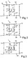
- Fig. 1 shows the circuit diagram of an energy storage device 1 for a motor vehicle with a first energy store 2 and a second energy store 3 with a first plus pole 4 of the first energy store 2 and a second plus pole 5 of the second energy store 3 and a first minus pole 6 of the first energy store 2 and a second minus pole 7 of the second energy store 3.
- the Energy storage device 1 also has a charging connection 8 for charging the energy stores 2, 3 and an operating connection 9 for supplying one or more consumers through the energy storage device 1.
- the energy storage device 1 here comprises a switching device which comprises a plurality of, in the example shown, seven switching elements S1 to S7. By means of these switching elements S1 to S7, the energy stores 2, 3 can optionally be connected in series and in parallel.
- the switching elements are simple switches which can either switch an electrical connection on or off according to the digital principle.
- the fifth switching element S5 is now permanently coupled to the first positive pole 4 and the second negative pole 7. Conversely, it could also be electrically coupled to the first negative pole 6 and the second positive pole 5 in the same way, in which case the switching device or the energy storage device would have the same effect, since the positive and negative poles would also have to be interchanged for the circuits mentioned below.
- the fifth switching element S5 is coupled to the electrical poles of opposite polarity of the two energy stores 2, 3 and to the fifth switching element S5 the energy stores 2, 3 independently of the further switching elements S1 to S4 and S6, S7 or a state of the same can be connected in series. Of course this is done in such a way that short circuits are avoided. This can be implemented or taken into account, for example, in control electronics of the switching device.
- the fifth switching element S5 thus enables a series connection of the two energy stores 2, 3 or partial batteries. Since the switching element S5 is not responsible for the activation, and thus not for an all-pole disconnection or decoupling of the energy stores 2, 3 from the charging and / or operating connection 8, 9, the fifth switching element S5 can also be implemented as a semiconductor component without any relevant Violate safety regulations in high-voltage batteries.
- the first switching element S1 is now arranged electrically between the positive poles 4, 5 of the energy stores 2, 3 and the positive pole 10 of the operating connection.
- the second switching element S2 is here arranged electrically between the negative poles 6, 7 of the energy stores 2, 3 and the negative pole 11 of the operating connection 9.
- the two switching elements S1, S2 can thus be used to completely separate the operating connection 9, that is to say all-pole, from the energy stores 2, 3.
- the third switching element S3 is arranged between the electrical positive poles 4, 5 of the energy stores 2, 3 and the positive pole 12 of the charging connection 8.
- the fourth switching element S4 is accordingly arranged between the negative poles 6, 7 of the energy stores 2, 3 and a negative pole 13 of the charging connector 8.
- the two switching elements S3, S4 can be used in this way to decouple the charging connection 8 from the energy stores 2, 3 and to switch them off in all poles.
- the third and fourth switching elements S3, S4 can act as charging contactors at the same time.
- the sixth switching element S6 is now arranged electrically between the first electrical positive pole 4 on the one hand and the first switching element S1 and the second positive pole 5 on the other hand.
- the seventh switching element S7 is arranged between the second electrical negative pole 7 on the one hand and the first electrical negative pole 6 and the fourth switching element S4 on the other hand.
- the coupling of the energy stores 2, 3 to the charging or operating connection 8, 9, and accordingly do not have to meet the relevant safety requirements for all-pole separation they can also be used, for example, as a semiconductor switching element , for example as a transistor or as a diode.
- a first operating state for example normal driving operation, in which the energy stores 2, 3 are connected in series, can now be achieved by switching elements S1, S2 and S5 being closed, but switching elements S3, S4, S6 and S7 being open .
- a second operating state for example for charging at half the battery voltage, in which the energy stores 2, 3 are connected in parallel and in which the operating connection is switched on, that is to say electrically coupled to the energy stores 2, 3, can be achieved here by the switching elements S1 to S4 are closed, the switching element S5 is open and the switching elements S6 and S7 are in turn closed.
- An alternative second operating state which also enables charging at half the battery voltage, but with the operating connection switched off, can be achieved here by switches S1 and S2 being open, switching elements S3 and S4 closed, switching element S5 open and switching elements S6 and S7 are closed.
- a third operating state for example for Charging at full battery voltage, in which, in the present example, the operating connection is switched on and the energy stores 2, 3 are connected in series, can be achieved by switching elements S1 to S5 being closed, but switching elements S6 and S7 being open.
- the third operating state for example for charging at full battery voltage, can be set when the operating connection is switched off by switching elements S1 and S2 being open, switching elements S3 to S5 being closed and switching elements S6 and S7 being open.
- a fourth operating state for example for all-pole disconnection, can be achieved here by switching elements S1 to S4 being open. The switching state of the other switching elements S5 to S7 is then irrelevant.
- Fig. 2 shows the circuit diagram of an energy storage device 1 for a motor vehicle with a first energy store 2 and a second energy store 3 with a first plus pole 4 of the first energy store 2 and a second plus pole 5 of the second energy store 3 and a first minus pole 6 of the first energy store 2 and a second minus pole 7 of the second energy store 3.
- the energy storage device 1 also has a charging connection 8 for charging the energy stores 2, 3 and an operating connection 9 for supplying one or more consumers through the energy storage device 1.
- the energy storage device 1 here comprises a switching device which comprises a plurality of, in the example shown, seven switching elements S1 to S7. By means of these switching elements S1 to S7, the energy stores 2, 3 can optionally be connected in series and in parallel.
- the switching elements are simple switches which can either switch an electrical connection on or off according to the digital principle.
- the fifth switching element S5 is now permanently coupled to the first positive pole 4 and the second negative pole 7. Conversely, it could also be electrically coupled to the first negative pole 6 and the second positive pole 5 in the same way, in which case the switching device or the energy storage device would have the same effect, since the positive and negative poles would also have to be interchanged for the circuits mentioned below.
- the fifth switching element S5 is coupled to the electrical poles of opposite polarity of the two energy stores 2, 3 and to the fifth switching element S5 the energy stores 2, 3 independently of the further switching elements S1 to S4 and S6, S7 or a state of the same can be connected in series. Of course this is done in such a way that short circuits are avoided. This can be implemented or taken into account, for example, in control electronics of the switching device.
- the first switching element S1 is now arranged between the second positive pole 5 on the one hand and the positive pole of the operating connection 9, the third switching element S3 and the sixth switching element S6 on the other hand.
- the second switching element S2 is arranged or electrically connected between the first negative pole 6 on the one hand and the negative pole 11 of the operating connection 9 and the fourth switching element S4 or the negative pole 13 of the charging connection 8 and the seventh switching element S7 or the second negative pole 7 on the other.
- the third switching element S3 is here arranged between the positive pole 12 of the charging connection 8 and the remaining components, in particular the first and the sixth switching element S1, S6 and the positive poles 4, 5 of the energy stores 2, 3 and the positive pole 10 of the operating connection.
- the fourth switching element S4 is accordingly arranged between the negative pole 13 of the charging connection 8 with the remaining components of the energy storage device 1, in particular the second switching element S2 and the seventh switching element S7 or the first negative pole 6 and the second negative pole 7 and the negative pole 11 of the operating connection.
- the all-pole disconnection of the charging connection 8 can be achieved by means of the switching elements S3, S4.
- the switching elements S3, S4 can also function as charging contactors.
- the sixth switching element S6 is here arranged between the first positive pole 4 on the one hand and the positive pole 10 of the operating connection 9 and the switching elements S1 and S3 or the second positive pole 5 and the positive pole 12 of the charging connection 8 on the other hand.
- the switching element S7 is arranged electrically between the second negative pole 7 on the one hand and the negative pole 7 of the operating connection 9 on the one hand and the switching elements S2 and S4 or the first electrical negative pole 6 and the electrical negative pole 13 of the charging connection 8 on the other hand. All-pole disconnection can thus be achieved by means of the switching elements S1, S2, S6 and S7, in particular from the operating connection 9.
- the two energy stores 2, 3 can be connected in parallel by the switching elements S1, S2, S6 and S7.
- the first operating state for example normal driving operation with energy storage devices 2, 3 connected in series
- switching elements S1, S2 and S5 being closed and switching elements S3, S4, S6 and S7 open.
- the second state for example for charging at half the battery voltage, with energy stores 2, 3 connected in parallel, can be achieved here by switching elements S1 to S4 being closed, switching element S5 being open and switching elements S6 and S7 being closed.
- the third operating state for example for charging at full battery voltage, with energy stores 2, 3 connected in series can be achieved by switching elements S1 to S5 being closed, but switching elements S6 and S7 being open.
- the fourth state for example for all-pole disconnection, can be achieved by switching elements S1, S2, S6 and S7 being open. In this case, the switching state of the switching elements S3, S4 and S5 is not important.
- Fig. 3 shows the circuit diagram of an energy storage device 1 for a motor vehicle with a first energy store 2 and a second energy store 3 with a first plus pole 4 of the first energy store 2 and a second plus pole 5 of the second energy store 3 and a first minus pole 6 of the first energy store 2 and a second minus pole 7 of the second energy store 3.
- the energy storage device 1 also has a charging connection 8 for charging the energy stores 2, 3 and an operating connection 9 for supplying one or more consumers through the energy storage device 1.
- the energy storage device 1 here comprises a switching device which comprises a plurality of, in the example shown, seven switching elements S1 to S7. By means of these switching elements S1 to S7, the energy stores 2, 3 can optionally be connected in series and in parallel.
- the switching elements are simple switches which can either switch an electrical connection on or off according to the digital principle.
- the fifth switching element S5 is now permanently coupled to the first positive pole 4 and the second negative pole 7. Conversely, it could also be electrically coupled to the first negative pole 6 and the second positive pole 5 in the same way, in which case the switching device or the energy storage device would have the same effect, since the positive and negative poles would also have to be interchanged for the circuits mentioned below.
- the fifth switching element S5 is coupled to the electrical poles of opposite polarity of the two energy stores 2, 3 and to the fifth switching element S5 Energy stores 2, 3 can be connected in series independently of the further switching elements S1 to S4 and S6, S7 or a state thereof. Of course, this is done in such a way that short circuits are avoided. This can be implemented or taken into account, for example, in control electronics of the switching device.
- the third switching element S3 is arranged between the positive pole 12 of the charging connection 8 on the one hand and the first switching element S1 and the positive pole 10 of the operating connection 9.
- the fourth switching element S4 is accordingly arranged between the negative pole 13 of the charging connection 8 on the one hand and the negative pole 11 of the operating connection 9 and the second switching element S2.
- the two switching elements S3, S4 can be used in this way to decouple the charging connection 8 from the energy stores 2, 3 and to switch them off in all poles.
- the third and fourth switching elements S3, S4 can thus act as charging contactors.
- the first switching element S1 is arranged between the second positive pole 5 on the one hand and the positive pole 10 of the operating connection 9 and the third switching element S3 or the positive pole 12 of the charging connection 8 on the other hand.
- the second switching element S2 is arranged electrically between the first negative pole 6 on the one hand and the negative pole 11 of the operating connection 9 and the fourth switching element S4 or the negative pole 13 of the shop connection 8 on the other hand.
- the two switching elements S1 and S2 accordingly ensure that the all-pole disconnection of the energy stores 2, 3 opposite or from the operating connection 9 is ensured.
- the switching elements S1 and S2 the all-pole disconnection mentioned can also be implemented with respect to the charging connection 8.
- the sixth switching element S6 is arranged between the first positive pole 4 and the second positive pole 5.
- the seventh switching element S7 is arranged electrically between the first negative pole 6 and the second negative pole 7.
- a parallel connection of the energy stores 2, 3 can thus be switched by means of the switching elements S6 and S7. Since the switching elements S6 and S7 here are not responsible for the activation or all-pole disconnection of the energy stores 2, 3 or must be used, a design as a semiconductor switching element is also possible. For example, transistors or diodes can be used here.
- the first operating state for example normal driving, with energy storage devices 2, 3 connected in series
- the second operating state for example for charging at half the operating voltage, with energy stores 2, 3 connected in parallel
- the third state for example for charging at full battery voltage, with energy stores 2, 3 connected in series
- the fourth state for example all-pole disconnection, can be achieved here by switching elements S1 and S2 being open and the remaining switching elements S3 to S7 having any state between open or closed.
- a flexible interconnection concept that allows four different operating states is thus integrated in an elegant manner, using the switching elements that are already partly due to the relevant safety regulations for high-voltage batteries with voltages above 60 volts, and thus charging the corresponding energy stores 2, 3 at one Charging infrastructure with a charging voltage falling below the operating voltages provided by the energy storage device 1 in comparison with driving operation is possible with little effort and little space requirement.
Landscapes
- Engineering & Computer Science (AREA)
- Power Engineering (AREA)
- Life Sciences & Earth Sciences (AREA)
- Sustainable Development (AREA)
- Sustainable Energy (AREA)
- Transportation (AREA)
- Mechanical Engineering (AREA)
- Charge And Discharge Circuits For Batteries Or The Like (AREA)
- Electric Propulsion And Braking For Vehicles (AREA)
- Secondary Cells (AREA)
Description
Die Erfindung betrifft eine Energiespeichereinrichtung für einen Kraftwagen gemäß dem Oberbegriff von Patentanspruch 1.The invention relates to an energy storage device for a motor vehicle according to the preamble of
In modernen Kraftwagen kommt oftmals eine Energiespeichereinrichtung oder eine Batterieanordnung zum Einsatz, welche mit einer höheren Spannung als die konventionellen 12 oder 24 Volt betrieben werden. Gerade bei Kraftwagen, welche auch über einen elektrischen Antriebsmotor verfügen, können Spannungen von mehreren 100 Volt als Nenn- oder Betriebsspannung vorgesehen sein. Derartige Energiespeichereinrichtungen werden typischerweise von einer kraftwagenexternen Ladeeinrichtung, welche Teil einer Ladeinfrastruktur ist, geladen. Ist nun ein Kraftwagen auf eine höhere Spannung ausgelegt beziehungsweise weist eine Energiespeichereinrichtung mit einer höheren Nominalspannung auf, als die Ladeinfrastruktur sie bereitstellt, kann die Energiespeichereinrichtung beziehungsweise die Batterieanordnung nicht ohne Weiteres durch die Ladeinfrastruktur geladen werden. Üblicherweise wird dieses Problem durch eine leistungselektronische Schaltung gelöst, welche groß, teuer und schwer ist.In modern motor vehicles, an energy storage device or a battery arrangement is often used, which are operated with a higher voltage than the conventional 12 or 24 volts. In the case of motor vehicles which also have an electric drive motor, voltages of several 100 volts can be provided as the nominal or operating voltage. Such energy storage devices are typically charged by a charging device external to the motor vehicle, which is part of a charging infrastructure. If a motor vehicle is now designed for a higher voltage or has an energy storage device with a higher nominal voltage than the charging infrastructure provides, the energy storage device or the battery arrangement cannot readily be charged by the charging infrastructure. This problem is usually solved by a power electronic circuit that is large, expensive and heavy.
In diesem Zusammenhang offenbart die
Des Weiteren offenbart die
In der
Es stellt sich die Aufgabe, eine Batterieanordnung oder Energiespeichereinrichtung in einem Kraftwagen bereitzustellen, mit der das beschriebene Problem auf effiziente Weise gelöst wird und insbesondere einschlägige Sicherheitsvorschriften für den Betrieb einer Energiespeichereinrichtung in einem Kraftwagen erfüllt werden.The object is to provide a battery arrangement or energy storage device in a motor vehicle, with which the problem described is solved in an efficient manner and, in particular, relevant safety regulations for the operation of an energy storage device in a motor vehicle are fulfilled.
Diese Aufgabe wird durch den Gegenstand der unabhängigen Patentansprüche gelöst. Vorteilhafte Ausführungsformen ergeben sich aus den abhängigen Patentansprüchen, der Beschreibung und den Figuren.This object is achieved by the subject matter of the independent claims. Advantageous embodiments result from the dependent claims, the description and the figures.
Die Erfindung betrifft eine Energiespeichereinrichtung oder eine Batterieanordnung für einen Kraftwagen. Die Energiespeichereinrichtung weist einen ersten und einen zweiten Energiespeicher zum Speichern elektrischer Energie auf. Sie kann auch mehr als zwei Energiespeicher aufweisen. Die Energiespeicher können beispielsweise Batterien oder Kondensatoren umfassen. Die Energiespeicher können dabei ein gemeinsames Gehäuse aufweisen. Die Energiespeicher oder Teilbatterien können dabei eine gleiche Spannung und/oder eine gleiche maximale Energiemenge oder -kapazität bereitstellen. Die Energiespeichereinrichtung kann somit als eine umschaltbare und/oder teilbare Energiespeichereinrichtung bezeichnet werden. Die Energiespeichereinrichtung weist außerdem zwei Anschlüsse auf, einen Ladeanschluss zum Laden der Energiespeicher über eine kraftwagenexterne Ladeinfrastruktur, sowie einen Betriebsanschluss zum Anschließen und Betrieb eines kraftwageninternen Verbrauchers oder Generators an der Energiespeichereinrichtung. Überdies weist die Energiespeichereinrichtung eine Schalteinrichtung auf, die mehrere, also beispielsweise drei, fünf oder sieben Schaltelemente aufweist, und mittels welcher die Energiespeicher wahlweise in Serie oder parallel schaltbar sind. Bei den Schaltelementen kann es sich um einfache Schalter handeln, mittels welchen eine elektrische Leitung zwischen zwei Anschlüssen herstellbar oder trennbar ist. Das kann beispielsweise durch eine vollständige Trennung oder eine vollständige Kopplung (digitales "0-1-Prinzip") realisiert sein.The invention relates to an energy storage device or a battery arrangement for a motor vehicle. The energy storage device has a first and a second energy store for storing electrical energy. It can also have more than two energy stores. The energy stores can include batteries or capacitors, for example. The energy storage devices can have a common housing. The energy stores or partial batteries can provide the same voltage and / or the same maximum amount or capacity of energy. The energy storage device can thus be referred to as a switchable and / or divisible energy storage device. The energy storage device also has two connections, a charging connection for charging the energy stores via a charging infrastructure external to the motor vehicle, and an operating connection for connecting and operating a consumer or generator inside the motor vehicle to the energy storage device. In addition, the energy storage device has a switching device which has a plurality of, for example three, five or seven, switching elements and by means of which the energy stores can be connected either in series or in parallel. The switching elements can be simple switches by means of which an electrical line can be produced or separated between two connections. This can be achieved, for example, by a complete separation or a complete coupling (digital "0-1 principle").
Wesentlich ist hier, dass ein Schaltelement, welches im Folgenden als fünftes Schaltelement bezeichnet wird, der Schalteinrichtung dauerhaft mit den elektrischen Polen entgegengesetzter Polarität von den Energiespeichern elektrisch gekoppelt ist. Das fünfte Schaltelement dient somit der elektrischen Kopplung von Plus- und Minuspol beziehungsweise Minus- und Pluspol der beiden Energiespeicher und ihrem Schalten in Serie. Mit dem fünften Schaltelement sind die Energiespeicher unabhängig von den weiteren Schaltelementen der Schalteinrichtung oder von einem Schaltzustand der weiteren Schaltelemente der Schalteinrichtung in Serie schaltbar.It is essential here that a switching element, which is referred to below as the fifth switching element, of the switching device is permanently electrically coupled to the electrical poles of opposite polarity from the energy stores. The fifth switching element thus serves for the electrical coupling of the positive and negative pole or the negative and positive pole of the two energy stores and their switching in series. With the fifth switching element, the energy stores can be connected in series independently of the further switching elements of the switching device or from a switching state of the further switching elements of the switching device.
Das hat den Vorteil, dass die beiden Energiespeicher mit geringem Aufwand in Serie oder parallel geschaltet werden können. Überdies kann die Schalteinrichtung in einem Gehäuse mit der Energiespeichereinrichtung realisiert werden, so dass die Steuerung der Schaltelemente kompakt im Kraftwagen realisiert ist. Da das fünfte Schaltelement keine weiteren Funktionen hat, insbesondere nicht für eine vorschriftsmäßige allpolige Trennung der Energiespeichereinrichtung bzw. der Energiespeicher dient, kann es auch als Halbleiterschaltelement, beispielsweise als Diode oder Transistor realisiert werden, ohne entsprechende einschlägige Sicherheitsvorschriften für Hochvoltbatterien, welche eine allpolige Spannungsabschaltung von Energiespeichern in einem Kraftfahrzeug vorschreiben, zu erfüllen. Unter einer Hochvoltbatterie kann hier eine Batterie mit mehr als 60V Nominalspannung verstanden werden.This has the advantage that the two energy stores can be connected in series or in parallel with little effort. In addition, the switching device can be implemented in a housing with the energy storage device, so that the control of the switching elements is implemented in a compact manner in the motor vehicle. Since the fifth switching element has no further functions, in particular is not used for a correct all-pole separation of the energy storage device or the energy storage device, it can also be implemented as a semiconductor switching element, for example as a diode or transistor, without corresponding relevant safety regulations for high-voltage batteries, which have an all-pole voltage shutdown of Prescribe energy storage in a motor vehicle to meet. A high-voltage battery can be understood here to mean a battery with a nominal voltage of more than 60V.
Somit wird durch das fünfte Schaltelement ermöglicht, dass durch die Schalteinrichtung die Energiespeichereinrichtung in vier unterschiedliche Betriebszustände gebracht wird und ein Laden an einer Infrastruktur mit geringerer Spannung realisiert werden kann. Die vier möglichen Betriebszustände betreffen dabei einen ersten Betriebszustand zum Fahren bei einer normalen Batteriespannung, die den in Serie geschalteten Energiespeichereinrichtungen entspricht, einen zweiten Betriebszustand für ein Laden bei einer halben Batteriespannung, also einer Batteriespannung, welcher bei spannungsgleichen Energiespeichern einem der beiden Energiespeicher und somit den parallel geschalteten Energiespeichern entspricht, einen dritten Betriebszustand für ein Laden bei der normalen Batteriespannung, und einen vierten Betriebszustand mit einer allpoligen Spannungsabschaltung und Trennung der Energiespeicher von Ladeanschluss-und/oder Betriebsanschluss.The fifth switching element thus makes it possible for the switching device to bring the energy storage device into four different operating states and for charging to an infrastructure with a lower voltage. The four possible operating states relate to a first operating state for driving with a normal battery voltage, which corresponds to the energy storage devices connected in series, a second operating state for charging with half a battery voltage, i.e. a battery voltage, which, in the case of voltage-equal energy stores, is one of the two energy stores and thus the Energy storage connected in parallel corresponds to a third operating state for charging at normal battery voltage, and a fourth operating state with an all-pole voltage shutdown and separation of the energy storage from the charging connection and / or operating connection.
Auch ist erfindungsgemäß vorgesehen, dass mittels eines mit dem Pluspol des zweiten Energiespeichers gekoppelten ersten Schaltelements der Pluspol des zweiten
Energiespeichers elektrisch von dem Betriebsanschluss entkoppelbar ist und in manchen erfinderischen Ausführungen auch von dem Ladeanschluss entkoppelbar ist.It is also provided according to the invention that by means of a first switching element coupled to the positive pole of the second energy store, the positive pole of the second
The energy storage device can be electrically decoupled from the operating connection and, in some inventive designs, can also be decoupled from the charging connection.
Erfindungsgemäß ist in der Ausführungsform vorgesehen, dass mittels eines mit dem Minuspol des ersten Energiespeichers gekoppelten zweiten Schaltelements der Minuspol des ersten Energiespeichers elektrisch von dem Betriebsanschluss entkoppelbar ist und in manchen erfinderischen Ausführungen auch von dem Ladeanschluss entkoppelbar ist.According to the invention, it is provided in the embodiment that the negative pole of the first energy store can be electrically decoupled from the operating connection by means of a second switching element coupled to the negative pole of the first energy store, and can also be decoupled from the charging connection in some inventive embodiments.
Des Weiteren ist erfindungsgemäß vorgesehen, dass mittels eines dritten Schaltelements ein Pluspol des Ladeanschlusses elektrisch von den Pluspolen der Energiespeicher entkoppelbar ist und mittels eines vierten Schaltelements ein Minuspol des Ladeanschlusses elektrisch von den Minuspolen der Energiespeicher entkoppelbar ist, wobei drittes und/oder viertes Schaltelement insbesondere als Batterie- und/oder Ladeschütze ausgeführt sind.Furthermore, it is provided according to the invention that a positive pole of the charging connection can be electrically decoupled from the positive poles of the energy stores by means of a third switching element and that a negative pole of the charging connection can be electrically decoupled from the negative poles of the energy stores by means of a fourth switching element, the third and / or fourth switching element being in particular as Battery and / or charging contactors are designed.
Das hat den Vorteil, dass die Batterie- beziehungsweise Ladeschütze nicht nur für ihre herkömmliche Funktion genutzt werden, sondern in die für die unterschiedlichen Betriebszustände erforderliche Verschaltung mit einbezogen werden, was die Anzahl der Bauteile gering hält. Überdies werden so keine zusätzlichen Ladeschützen zum Gleichstromladen über den Ladeanschluss benötigt.This has the advantage that the battery or charging contactors are not only used for their conventional function, but are also included in the interconnection required for the different operating states, which keeps the number of components low. In addition, no additional charging contactors are required for DC charging via the charging connection.
In einer vorteilhaften Ausführungsform ist vorgesehen, dass mittels eines mit dem Pluspol des ersten Energiespeichers gekoppelten sechsten Schaltelements der Pluspol des ersten Energiespeichers elektrisch von dem Betriebsanschluss und von dem Ladeanschluss entkoppelbar ist.In an advantageous embodiment it is provided that by means of a sixth switching element coupled to the positive pole of the first energy store, the positive pole of the first energy store can be electrically decoupled from the operating connection and from the charging connection.
In einer weiteren bevorzugten Ausführungsform ist vorgesehen, dass mittels eines mit dem Minuspol des zweiten Energiespeichers gekoppelten siebten Schaltelements der Minuspol des zweiten Energiespeichers elektrisch von dem Betriebsanschluss und auch von dem Ladenanschluss entkoppelbar ist.In a further preferred embodiment it is provided that by means of a seventh switching element coupled to the negative pole of the second energy store, the negative pole of the second energy store can be electrically decoupled from the operating connection and also from the store connection.
Im Rahmen dieser Erfindung wurde zur besseren Lesbarkeit der Pol einer ersten Polarität als Minuspol bezeichnet und der Pol einer zweiten elektrischen Polarität eines Energiespeichers als Pluspol. Da dies eine bloße Konvention ist, kann der Minuspol im Rahmen dieser Offenbarung auch Pole einer elektrischen Polarität betreffen, welche in anderen Dokumenten als Pluspole bezeichnet sind. Entscheidend ist, dass der Minuspol im Rahmen dieser Erfindung einen ersten Pol und der Pluspol einen zweiten Pol mit entgegengesetzter Polarität betrifft.In the context of this invention, for better readability, the pole of a first polarity was designated as the negative pole and the pole of a second electrical polarity of an energy store as the positive pole. Since this is a mere convention, the negative pole can also relate to poles of an electrical polarity within the scope of this disclosure, which are referred to in other documents as positive poles. It is crucial that the negative pole in the context of this invention relates to a first pole and the positive pole to a second pole with opposite polarity.
Die vorstehend in der Beschreibung genannten Merkmale und Merkmalskombinationen, sowie die nachfolgend in der Figurenbeschreibung genannten und/oder in den Figuren alleine gezeigten Merkmale und Merkmalskombinationen sind nicht nur in der jeweils angegebenen Kombination, sondern auch in anderen Kombinationen verwendbar, ohne den Rahmen der Erfindung zu verlassen. Es sind somit auch Ausführungen von der Erfindung als umfasst und offenbart anzusehen, die in den Figuren nicht explizit gezeigt und erläutert sind, jedoch durch separierte Merkmalskombinationen aus den erläuterten Ausführungen hervorgehen und erzeugbar sind. Es sind auch Ausführungen und Merkmalskombinationen als offenbart anzusehen, die somit nicht alle Merkmale eines ursprünglich formulierten unabhängigen Anspruchs aufweisen. Es sind darüber hinaus Ausführungen und Merkmalskombinationen, insbesondere durch die oben dargelegten Ausführungen, als offenbart anzusehen, die über die in den Rückbezügen der Ansprüche dargelegten Merkmalskombinationen hinausgehen oder von diesen abweichen.The features and combinations of features mentioned above in the description, as well as the features and combinations of features mentioned below in the description of the figures and / or shown alone in the figures, can be used not only in the respectively specified combination, but also in other combinations, without the scope of the invention leave. Embodiments of the invention are thus also to be regarded as encompassed and disclosed, which are not explicitly shown and explained in the figures, but can be derived from the explanations explained and can be generated by separate combinations of features. Designs and combinations of features are also to be regarded as disclosed, which therefore do not have all the features of an originally formulated independent claim. In addition, versions and combinations of features, in particular those explained above, are to be regarded as disclosed which go beyond or differ from the combinations of features set out in the references of the claims.
Ausführungsbeispiele der Erfindung werden nachfolgend anhand schematischer Zeichnungen näher erläutert. Dabei zeigen:
- Fig. 1
- ein Schaltbild einer ersten beispielhaften Ausführungsform einer Energiespeichereinrichtung;
- Fig. 2
- ein Schaltbild einer zweiten beispielhaften Ausführungsform einer Energiespeichereinrichtung; und
- Fig. 3
- ein Schaltbild einer dritten beispielhaften Ausführungsform einer Energiespeichereinrichtung.
- Fig. 1
- a circuit diagram of a first exemplary embodiment of an energy storage device;
- Fig. 2
- a circuit diagram of a second exemplary embodiment of an energy storage device; and
- Fig. 3
- a circuit diagram of a third exemplary embodiment of an energy storage device.
In den Figuren werden dabei gleiche oder funktionsgleiche Elemente mit den gleichen Bezugszeichen versehen.In the figures, elements that are the same or have the same function are provided with the same reference symbols.
Im gezeigten Beispiel ist nun das fünfte Schaltelement S5 dauerhaft mit dem ersten Pluspol 4 und dem zweiten Minuspol 7 gekoppelt. Es könnte auch genauso umgekehrt mit dem ersten Minuspol 6 und dem zweiten Pluspol 5 elektrisch gekoppelt sein, dann würde eine gleiche Wirkung der Schalteinrichtung beziehungsweise der Energiespeichereinrichtung bewirkt, indem auch für die im Folgenden genannten Verschaltungen jeweils Plus- und Minuspole vertauscht werden müssten. Aus Gründen der besseren Lesbarkeit wird hier darauf verzichtet, wesentlich ist, dass das fünfte Schaltelement S5 mit den elektrischen Polen entgegengesetzter Polarität der beiden Energiespeicher 2, 3 gekoppelt ist und mit dem fünften Schaltelement S5 die Energiespeicher 2, 3 unabhängig von den weiteren Schaltelementen S1 bis S4 und S6, S7 beziehungsweise einem Zustand Derselben in Serie schaltbar sind. Selbstverständlich erfolgt dies derart, dass Kurzschlüsse vermieden werden. Dies kann beispielsweise in einer Steuerelektronik der Schalteinrichtung realisiert sein beziehungsweise berücksichtigt werden.In the example shown, the fifth switching element S5 is now permanently coupled to the first
Mittels des fünften Schaltelements S5 wird somit eine Serienschaltung der beiden Energiespeicher 2, 3 oder Teilbatterien ermöglicht. Da das Schaltelement S5 nicht für die Freischaltung zuständig ist, und somit nicht für eine allpolige Abschaltung oder Entkopplung der Energiespeicher 2, 3 von Lade- und/oder Betriebsanschluss 8, 9, kann das fünfte Schaltelement S5 auch als Halbleiterbauteil ausgeführt werden, ohne dabei einschlägige Vorschriften bezüglich der Sicherheit in Hochvoltbatterien zu verletzen.The fifth switching element S5 thus enables a series connection of the two
Im gezeigten Beispiel ist nun das erste Schaltelement S1 elektrisch zwischen den Pluspolen 4, 5 der Energiespeicher 2, 3 und dem Pluspol 10 des Betriebsanschlusses angeordnet. Das zweite Schaltelement S2 ist hier elektrisch zwischen den Minuspolen 6, 7 der Energiespeicher 2, 3 und dem Minuspol 11 des Betriebsanschlusses 9 angeordnet. Die beiden Schaltelemente S1, S2 können somit genutzt werden, um den Betriebsanschluss 9 vollständig, also allpolig von den Energiespeichern 2, 3 abzutrennen.In the example shown, the first switching element S1 is now arranged electrically between the
Das dritte Schaltelement S3 ist vorliegend zwischen den elektrischen Pluspolen 4, 5 der Energiespeicher 2, 3 und dem Pluspol 12 des Ladeanschlusses 8 angeordnet. Das vierte Schaltelement S4 ist entsprechend zwischen den Minuspolen 6, 7 der Energiespeicher 2, 3 und einem Minuspol 13 des Ladeanschlusses 8 angeordnet. Die beiden Schaltelemente S3, S4 können so genutzt werden, um den Ladeanschluss 8 von den Energiespeichern 2, 3 zu entkoppeln und diesen so allpolig abzuschalten. Das dritte und das vierte Schaltelement S3, S4 können gleichzeitig als Ladeschütze fungieren.In the present case, the third switching element S3 is arranged between the electrical
Vorliegend ist nun das sechste Schaltelement S6 elektrisch zwischen dem ersten elektrischen Pluspol 4 einerseits und dem ersten Schaltelement S1 sowie dem zweiten Pluspol 5 andererseits angeordnet. Analog dazu ist das siebte Schaltelement S7 zwischen dem zweiten elektrischen Minuspol 7 einerseits und dem ersten elektrischen Minuspol 6 sowie dem vierten Schaltelement S4 andererseits angeordnet. Mittels des sechsten und des siebten Schaltelements S6, S7 wird so eine Parallelschaltung der beiden Energiespeicher 2, 3, die beispielsweise jeweils Teilbatterien sein können, ermöglicht. Da die beiden Schaltelemente S6 und S7 nicht für die Freischaltung, also die Kopplung der Energiespeicher 2, 3 mit Lade- oder Betriebsanschluss 8, 9 zuständig sind, und entsprechend nicht den einschlägigen Sicherheitsanforderungen für eine allpolige Trennung genügen müssen, können sie beispielsweise auch als Halbleiterschaltelement, zum Beispiel als Transistor oder als Diode, ausgeführt sein.In the present case, the sixth switching element S6 is now arranged electrically between the first electrical
Ein erster Betriebszustand, zum Beispiel ein normaler Fahrbetrieb, in welchem die Energiespeicher 2, 3 in Serie geschaltet sind, kann nun erzielt werden, indem die Schaltelemente S1, S2 und S5 geschlossen sind, die Schaltelemente S3, S4, S6 und S7 jedoch offen sind. Ein zweiter Betriebszustand, zum Beispiel zum Laden bei halber Batteriespannung, in welchem die Energiespeicher 2, 3 parallel geschaltet sind, und in welchem der Betriebsanschluss zugeschaltet, also mit den Energiespeichern 2, 3 elektrisch gekoppelt ist, kann hier erreicht werden, indem die Schaltelemente S1 bis S4 geschlossen sind, das Schaltelement S5 offen ist und die Schaltelemente S6 und S7 wiederum geschlossen sind. Ein alternativer zweiter Betriebszustand, welcher ebenfalls ein Laden bei halber Batteriespannung ermöglicht, jedoch bei abgeschaltetem Betriebsanschluss, kann hier erreicht werden, indem die Schalter S1 und S2 offen sind, die Schaltelemente S3 und S4 geschlossen, das Schaltelement S5 offen und die Schaltelemente S6 und S7 geschlossen sind. Ein dritter Betriebszustand, zum Beispiel für ein Laden bei voller Batteriespannung, bei welchem im vorliegenden Beispiel der Betriebsanschluss zugeschaltet ist und die Energiespeicher 2, 3 in Serie geschaltet sind, kann erreicht werden, indem die Schaltelemente S1 bis S5 geschlossen, die Schaltelemente S6 und S7 jedoch offen sind. Alternativ kann der dritte Betriebszustand, zum Beispiel zum Laden bei voller Batteriespannung, bei einem abgeschalteten Betriebsanschluss eingestellt werden, indem die Schaltelemente S1 und S2 offen, die Schaltelemente S3 bis S5 geschlossen und die Schaltelemente S6 und S7 offen sind. Ein vierter Betriebszustand, zum Beispiel zur allpoligen Abschaltung, kann hier erreicht werden, indem die Schaltelemente S1 bis S4 offen sind. Dabei kommt es auf den Schaltzustand der weiteren Schaltelemente S5 bis S7 dann nicht an.A first operating state, for example normal driving operation, in which the
Im gezeigten Beispiel ist nun das fünfte Schaltelement S5 dauerhaft mit dem ersten Pluspol 4 und dem zweiten Minuspol 7 gekoppelt. Es könnte auch genauso umgekehrt mit dem ersten Minuspol 6 und dem zweiten Pluspol 5 elektrisch gekoppelt sein, dann würde eine gleiche Wirkung der Schalteinrichtung beziehungsweise der Energiespeichereinrichtung bewirkt, indem auch für die im Folgenden genannten Verschaltungen jeweils Plus- und Minuspole vertauscht werden müssten. Aus Gründen der besseren Lesbarkeit wird hier darauf verzichtet, wesentlich ist, dass das fünfte Schaltelement S5 mit den elektrischen Polen entgegengesetzter Polarität der beiden Energiespeicher 2, 3 gekoppelt ist und mit dem fünften Schaltelement S5 die Energiespeicher 2, 3 unabhängig von den weiteren Schaltelementen S1 bis S4 und S6, S7 beziehungsweise einem Zustand Derselben in Serie schaltbar sind. Selbstverständlich erfolgt dies derart, dass Kurzschlüsse vermieden werden. Dies kann beispielsweise in einer Steuerelektronik der Schalteinrichtung realisiert sein beziehungsweise berücksichtigt werden.In the example shown, the fifth switching element S5 is now permanently coupled to the first
Im gezeigten Beispiel ist nun das erste Schaltelement S1 zwischen dem zweiten Pluspol 5 einerseits und dem Pluspol des Betriebsanschlusses 9, dem dritten Schaltelement S3 und dem sechsten Schaltelement S6 andererseits angeordnet. Analog ist das zweite Schaltelement S2 zwischen dem ersten Minuspol 6 einerseits und dem Minuspol 11 des Betriebsanschlusses 9 sowie dem vierten Schaltelement S4 beziehungsweise dem Minuspol 13 des Ladeanschlusses 8 sowie dem siebten Schaltelement S7 beziehungsweise dem zweiten Minuspol 7 andererseits angeordnet beziehungsweise elektrisch verschaltet.In the example shown, the first switching element S1 is now arranged between the second
Das dritte Schaltelement S3 ist hier zwischen dem Pluspol 12 des Ladeanschlusses 8 sowie den restlichen Komponenten, insbesondere dem ersten und dem sechsten Schaltelement S1, S6 sowie den Pluspolen 4, 5 der Energiespeicher 2, 3 und dem Pluspol 10 des Betriebsanschlusses angeordnet. Das vierte Schaltelement S4 ist entsprechend zwischen dem Minuspol 13 des Ladeanschlusses 8 mit den restlichen Komponenten der Energiespeichereinrichtung 1, insbesondere dem zweiten Schaltelement S2 und dem siebten Schaltelement S7 beziehungsweise dem ersten Minuspol 6 und dem zweiten Minuspol 7 sowie dem Minuspol 11 des Betriebsanschlusses angeordnet. Mittels der Schaltelemente S3, S4 kann die allpolige Abschaltung des Ladeanschlusses 8 erreicht werden. Optional können die Schaltelemente S3, S4 auch als Ladeschütze fungieren.The third switching element S3 is here arranged between the
Das sechste Schaltelement S6 ist hier zwischen dem ersten Pluspol 4 einerseits sowie dem Pluspol 10 des Betriebsanschlusses 9 und den Schaltelementen S1 und S3 beziehungsweise dem zweiten Pluspol 5 und dem Pluspol 12 des Ladeanschlusses 8 andererseits angeordnet. Entsprechend ist das Schaltelement S7 elektrisch zwischen dem zweiten Minuspol 7 einerseits und dem Minuspol 7 des Betriebsanschlusses 9 einerseits sowie den Schaltelementen S2 und S4 beziehungsweise ersten elektrischen Minuspol 6 und dem elektrischen Minuspol 13 des Ladeanschlusses 8 andererseits angeordnet. Mittels der Schaltelemente S1, S2, S6 und S7 kann so eine allpolige Abschaltung erreicht werden, insbesondere von dem Betriebsanschluss 9. Zugleich ist durch die Schaltelemente S1, S2, S6 und S7 eine Parallelschaltung der beiden Energiespeicher 2, 3 realisierbar.The sixth switching element S6 is here arranged between the first
Der erste Betriebszustand, zum Beispiel ein normaler Fahrbetrieb mit seriell geschalteten Energiespeichern 2, 3 kann hier realisiert werden, indem die Schaltelemente S1, S2 und S5 geschlossen sind sowie die Schaltelemente S3, S4, S6 und S7 offen. Der zweite Zustand, zum Beispiel zum Laden bei halber Batteriespannung, mit parallel geschalteten Energiespeichern 2, 3, kann hier erreicht werden, indem die Schaltelemente S1 bis S4 geschlossen, das Schaltelement S5 offen und die Schaltelemente S6 und S7 geschlossen sind. Der dritte Betriebszustand, zum Beispiel zum Laden bei voller Batteriespannung, mit in Serie geschalteten Energiespeichern 2, 3 kann erreicht werden, indem die Schaltelemente S1 bis S5 geschlossen, die Schaltelemente S6 und S7 jedoch offen sind. Der vierte Zustand, zum Beispiel zur allpoligen Abschaltung, kann erreicht werden, indem die Schaltelemente S1, S2, S6 und S7 offen sind. Auf den Schaltzustand der Schaltelemente S3, S4 und S5 kommt es in diesem Fall nicht an.The first operating state, for example normal driving operation with
Im gezeigten Beispiel ist nun das fünfte Schaltelement S5 dauerhaft mit dem ersten Pluspol 4 und dem zweiten Minuspol 7 gekoppelt. Es könnte auch genauso umgekehrt mit dem ersten Minuspol 6 und dem zweiten Pluspol 5 elektrisch gekoppelt sein, dann würde eine gleiche Wirkung der Schalteinrichtung beziehungsweise der Energiespeichereinrichtung bewirkt, indem auch für die im Folgenden genannten Verschaltungen jeweils Plus- und Minuspole vertauscht werden müssten. Aus Gründen der besseren Lesbarkeit wird hier darauf verzichtet, wesentlich ist, dass das fünfte Schaltelement S5 mit den elektrischen Polen entgegengesetzter Polarität der beiden Energiespeicher 2, 3 gekoppelt ist und mit dem fünften Schaltelement S5 die Energiespeicher 2, 3 unabhängig von den weiteren Schaltelementen S1 bis S4 und S6, S7 beziehungsweise einem Zustand Derselben in Serie schaltbar sind. Selbstverständlich erfolgt dies derart, dass Kurzschlüsse vermieden werden. Dies kann beispielsweise in einer Steuerelektronik der Schalteinrichtung realisiert sein beziehungsweise berücksichtigt werden.In the example shown, the fifth switching element S5 is now permanently coupled to the first
Das dritte Schaltelement S3 ist vorliegend zwischen dem Pluspol 12 des Ladeanschlusses 8 einerseits und dem ersten Schaltelement S1 und dem Pluspol 10 des Betriebsanschlusses 9 angeordnet. Das vierte Schaltelement S4 ist entsprechend zwischen dem Minuspol 13 des Ladeanschlusses 8 einerseits und dem Minuspol 11 des Betriebsanschlusses 9 und dem zweiten Schaltelement S2 angeordnet. Die beiden Schaltelemente S3, S4 können so genutzt werden, um den Ladeanschluss 8 von den Energiespeichern 2, 3 zu entkoppeln und diesen so allpolig abzuschalten. Das dritte und das vierte Schaltelement S3, S4 können somit als Ladeschütze fungieren.In the present case, the third switching element S3 is arranged between the
Das erste Schaltelement S1 ist vorliegend zwischen dem zweiten Pluspol 5 einerseits und dem Pluspol 10 des Betriebsanschlusses 9 sowie dem dritten Schaltelement S3 beziehungsweise dem Pluspol 12 des Ladeanschlusses 8 andererseits angeordnet. Entsprechend ist das zweite Schaltelement S2 elektrisch zwischen dem ersten Minuspol 6 einerseits und dem Minuspol 11 des Betriebsanschlusses 9 sowie dem vierten Schaltelement S4 beziehungsweise dem Minuspol 13 des Ladenanschlusses 8 andererseits angeordnet. Die beiden Schaltelemente S1 und S2 stellen entsprechend die allpolige Abschaltung der Energiespeicher 2, 3 gegenüber beziehungsweise von dem Betriebsanschluss 9 sicher. Mittels der Schaltelemente S1 und S2 ist die genannte allpolige Abschaltung auch gegenüber dem Ladeanschluss 8 umsetzbar.In the present case, the first switching element S1 is arranged between the second
Zwischen dem ersten Pluspol 4 und dem zweiten Pluspol 5 ist vorliegend das sechste Schaltelement S6 angeordnet. Entsprechend ist elektrisch zwischen dem ersten Minuspol 6 und dem zweiten Minuspol 7 das siebte Schaltelement S7 angeordnet. Somit ist mittels der Schaltelemente S6 und S7 eine Parallelschaltung der Energiespeicher 2, 3 schaltbar. Da die Schaltelemente S6 und S7 hier nicht für die Freischaltung beziehungsweise allpolige Abschaltung der Energiespeicher 2, 3 zuständig sind beziehungsweise genutzt werden müssen, ist auch eine Ausführung als Halbleiterschaltelement möglich. Zum Beispiel können hier Transistoren oder Dioden verwendet werden.In the present case, the sixth switching element S6 is arranged between the first
Der erste Betriebszustand, zum Beispiel der normale Fahrbetrieb, mit seriell geschalteten Energiespeichern 2, 3, kann hier zum Beispiel erreicht werden, indem die Schaltelemente S1, S2 und S5 geschlossen sind, und die Schaltelemente S3, S4 sowie S6 und S7 offen bleiben. Der zweite Betriebszustand, zum Beispiel für ein Laden bei halber Betriebsspannung, mit parallel geschalteten Energiespeichern 2, 3, kann hier erreicht werden, indem die Schaltelemente S1 bis S4 geschlossen sind, das Schaltelement S5 offen und die Schaltelemente S6 und S7 geschlossen sind. Der dritte Zustand, zum Beispiel zum Laden bei voller Batteriespannung, mit seriell geschalteten Energiespeichern 2, 3, kann hier erreicht werden, indem die Schaltelemente S1 bis S5 geschlossen sind, die Schaltelemente S6 und S7 jedoch offen bleiben. Der vierte Zustand, zum Beispiel die allpolige Abschaltung, kann hier erreicht werden, indem die Schaltelemente S1 und S2 offen sind und die restlichen Schaltelemente S3 bis S7 einen beliebigen Zustand zwischen offen oder geschlossen haben.The first operating state, for example normal driving, with
In allen genannten Ausführungsbeispielen wird somit auf eine elegante Weise unter Nutzung der teilweise bereits aufgrund einschlägiger Sicherheitsvorschriften für Hochvoltbatterien mit Spannungen über 60 Volt vorhandenen Schaltelementen ein flexibles Verschaltungskonzept integriert, welches vier unterschiedliche Betriebszustände erlaubt, und so ein Laden der entsprechenden Energiespeicher 2, 3 an einer Ladeinfrastruktur mit einer im Vergleich zum Fahrbetrieb durch die Energiespeichereinrichtung 1 bereitgestellten Betriebsspannungen unterschreitenden Ladespannung mit wenig Aufwand und geringem Platzbedarf ermöglicht.In all of the above-mentioned exemplary embodiments, a flexible interconnection concept that allows four different operating states is thus integrated in an elegant manner, using the switching elements that are already partly due to the relevant safety regulations for high-voltage batteries with voltages above 60 volts, and thus charging the corresponding
- 11
- EnergiespeichereinrichtungEnergy storage device
- 22nd
- Erster EnergiespeicherFirst energy storage
- 33rd
- Zweiter EnergiespeicherSecond energy storage
- 44th
- Erster PluspolFirst positive pole
- 55
- Zweiter PluspolSecond positive pole
- 66
- Erster MinuspolFirst negative pole
- 77
- Zweiter MinuspolSecond negative pole
- 88th
- LadeanschlussCharging port
- 99
- BetriebsanschlussOperating connection
- 1010th
- PluspolPositive pole
- 1111
- MinuspolNegative pole
- 1212th
- PluspolPositive pole
- 1313
- MinuspolNegative pole
- S1-S7S1-S7
- Erstes bis siebtes SchaltelementFirst to seventh switching element
Claims (15)
- Energy storage device (1) for a motor vehicle, comprising- a first energy store (2) having a first electric positive pole (4) and a first electric negative pole (6) and a second energy store (3) having a second electric positive pole (5) and a second electric negative pole (6) for storing electric energy;- a charging connection (8) for charging the energy stores (2, 3);- an operating connection (9) for the operation of a load at the energy storage device (1); and- a switching device which comprises a plurality of switching elements (S1-S7) and by means of which the energy stores (2, 3) can optionally be connected in series or in parallel, wherein a fifth switching element (S5) of the switching device is permanently connected electrically to the electric poles (4, 5, 6, 7) of opposite polarity of the energy stores (2, 3) and the energy stores (2, 3) can be connected in series with the fifth switching element (S5),
characterised in that- by means of a first switching element (S1) a positive pole (10) of the operating connection (9) can be electrically decoupled from the positive poles (4, 5) of the energy stores (2, 3), and- by means of a second switching element (S2) a negative pole (11) of the operating connection (9) can be electrically decoupled from the negative poles (6, 7) of the energy stores (2, 3), and- by means of a third switching element (S3) a positive pole (12) of the charging connection (8) can be electrically decoupled from the positive poles (4, 5) of the energy stores (2, 3), and- by means of a fourth switching element (S4) a negative pole (13) of the charging connection (8) can be electrically decoupled from the negative poles (6, 7) of the energy stores (2, 3), wherein the third and/or the fourth switching element (S3, S4) are designed as battery contactors or charging contactors, and wherein a sixth switching element (S6) is electrically located between the first positive pole (4) of the first energy store (2) on the one hand and the first switching element (S1) and the third switching element (S3) as well as the second positive pole (5) of the second energy store (3) on the other hand, and a seventh switching element (S7) is electrically located between the second negative pole (7) of the second energy store (3) on the one hand and the first negative pole (6) of the first energy store (2) as well as the second switching element (S2) and the fourth switching element (S4) on the other hand,
so that the fifth, sixth and seventh switching elements (S4, S6, S7) facilitate a parallel or series connection of the two energy stores (2, 3),
by providing that the two energy stores (2, 3) are connected in series if the fifth switching element (S5) is closed and the sixth and seventh switching elements (S6, S7) are open, and
that the two energy stores (2, 3) are connected in parallel if the sixth and seventh switching elements (S6, S7) are closed and the fifth switching element (S5) is open. - Energy storage device (1) according to claim 1,
characterised in that
by means of the sixth switching element (S6) coupled to the first positive pole (4) of the first energy store (2), the first positive pole (4) of the first energy store (2) can be electrically decoupled from the operating connection (9) and the charging connection (8). - Energy storage device (1) according to claim 1 or 2,
characterised in that
by means of the seventh switching element (S7) coupled to the second negative pole (7) of the second energy store (3), the second negative pole (7) of the second energy store (3) can be electrically decoupled from the operating connection (9) and also from the charging connection (8). - Energy storage device (1) according to any of the preceding claims, characterised in that
the first switching element (S1) and/or the second switching element (S2) is/are designed as battery contactor. - Energy storage device (1) according to any of the preceding claims, characterised in that
the fifth switching element (S5) and/or the sixth switching element (S6) and/or the seventh switching element (S7) is/are designed as semiconductor switching element. - Energy storage device (1) for a motor vehicle, comprising- a first energy store (2) having a first electric positive pole (4) and a first electric negative pole (6) and a second energy store (3) having a second electric positive pole (5) and a second electric negative pole (6) for storing electric energy;- a charging connection (8) for charging the energy stores (2, 3);- an operating connection (9) for the operation of a load at the energy storage device (1); and- a switching device which comprises a plurality of switching elements (S1-S7) and by means of which the energy stores (2, 3) can optionally be connected in series or in parallel, wherein a fifth switching element (S5) of the switching device is permanently connected electrically to the electric poles (4, 5, 6, 7) of opposite polarity of the energy stores (2, 3) and the energy stores (2, 3) can be connected in series with the fifth switching element (S5),
characterised in that- by means of a first switching element (S1) the second positive pole (5) of the second energy store (3) can be electrically decoupled from a positive pole (10) of the operating connection (9) and from a positive pole (12) of the charging connection (8), and- by means of a second switching element (S2) the first negative pole (6) of the first energy store (2) can be electrically decoupled from a negative pole (11) of the operating connection (9) and from a negative pole (13) of the charging connection (8), and- by means of a third switching element (S3) the positive pole (12) of the charging connection (8) can be electrically decoupled from the positive poles (4, 5) of the energy stores (2, 3), and- by means of a fourth switching element (S4) the negative pole (13) of the charging connection (8) can be electrically decoupled from the negative poles (6, 7) of the energy stores (2, 3), wherein the third and/or the fourth switching element (S3, S4) is/are designed as battery contactors or charging contactors, and wherein a sixth switching element (S6) is electrically located between the first positive pole (4) of the first energy store (2) on the one hand and the first switching element (S1) and the third switching element (S3) as well as the positive pole (10) of the operating connection (9) on the other hand, and a seventh switching element (S7) is electrically located between the second negative pole (7) of the second energy store (3) on the one hand and the second switching element (S2) and the fourth switching element (S4) as well as the negative pole (11) of the operating connection (9) on the other hand,
so that a parallel connection or series connection of the two energy stores (2, 3) is facilitated by the first, second, fifth, sixth and seventh switching element (S1, S2, S5, S6, S7),
by providing that the two energy stores (2, 3) are connected in series if the first, second and fifth switching elements (S1, S2, S5) are closed and the sixth and seventh switching elements (S6, S7) are open, and
that the two energy stores (2, 3) are connected in parallel if the first, second, sixth and seventh switching elements (S1, S2, S6, S7) are closed and the fifth switching element (S5) is open. - Energy storage device (1) according to claim 6,
characterised in that
by means of the first switching element (S1) coupled to the second positive pole (5) of the second energy store (3), the second positive pole (5) of the second energy store (3) can be electrically decoupled from the operating connection (9) and the charging connection (8), and
by means of the sixth switching element (S6) coupled to the first positive pole (4) of the first energy store (2), the first positive pole (4) of the first energy store (2) can be electrically decoupled from the operating connection (9) and the charging connection (8). - Energy storage device (1) according to claim 6 or 7,
characterised in that
by means of the second switching element (S2) coupled to the negative pole (6) of the first energy store (2), the negative pole (6) of the first energy store (2) can be electrically decoupled from operating connection (9) and the charging connection (8), and
by means of the seventh switching element (S7) coupled to the second negative pole (7) of the second energy store (3), the second negative pole (7) of the second energy store (3) can be electrically decoupled from operating connection (9) and also from the charging connection (8). - Energy storage device (1) according to any of claims 6 to 8,
characterised in that
the first switching element (S1) and/or the second switching element (S2) and/or the sixth switching element (S6) and/or the seventh switching element (S7) is/are designed as battery contactor. - Energy storage device (1) according to any of claims 6 to 9,
characterised in that
the fifth switching element (S5) is designed as semiconductor switching element. - Energy storage device (1) for a motor vehicle, comprising- a first energy store (2) having a first electric positive pole (4) and a first electric negative pole (6) and a second energy store (3) having a second electric positive pole (5) and a second electric negative pole (6) for storing electric energy;- a charging connection (8) for charging the energy stores (2, 3);- an operating connection (9) for the operation of a load at the energy storage device (1); and- a switching device which comprises a plurality of switching elements (S1-S7) and by means of which the energy stores (2, 3) can optionally be connected in series or in parallel, wherein a fifth switching element (S5) of the switching device is permanently connected electrically to the electric poles (4, 5, 6, 7) of opposite polarity of the energy stores (2, 3) and the energy stores (2, 3) can be connected in series with the fifth switching element (S5),
characterised in that- by means of a first switching element (S1) the first positive pole (4) of the first energy store (2) and the second positive pole (5) of the second energy store (3) can be electrically decoupled from a positive pole (10) of the operating connection (9) and from a positive pole (12) of the charging connection (8), and- by means of a second switching element (S2) the first negative pole (6) of the first energy store (2) and the second negative pole (7) of the second energy store (3) can be electrically decoupled from a negative pole (11) of the operating connection (9) and from a negative pole (13) of the charging connection (8), and- by means of a third switching element (S3) the positive pole (12) of the charging connection (8) can be electrically decoupled from the positive poles (4, 5) of the energy stores (2, 3), and- by means of a fourth switching element (S4) the negative pole (13) of the charging connection (8) can be electrically decoupled from the negative poles (6, 7) of the energy stores (2, 3), wherein the third and/or the fourth switching element (S3, S4) is/are designed as battery contactors or charging contactors, and wherein a sixth switching element (S6) is electrically located between the first positive pole (4) of the first energy store (2) on the one hand and the second positive pole (5) of the second energy store (3) on the other hand, and a seventh switching element (S7) is electrically located between the second negative pole (7) of the second energy store (3) on the one hand and the first negative pole (6) of the first energy store (2) as well as the second switching element (S2) on the other hand,
so that a parallel connection or series connection of the two energy stores (2, 3) is facilitated by the fifth, sixth and seventh switching elements (S5, S6, S7),
by providing that the two energy stores (2, 3) are connected in series if the fifth switching element (S5) is closed and the sixth and the seventh switching elements S6, S7) are open, and
that the two energy stores (2, 3) are connected in parallel if the sixth and seventh switching elements (S6, S7) are closed and the fifth switching element (S5) is open. - Energy storage device (1) according to claim 11,
characterised in that
by means of the first switching element (S1) electrically coupled to the second positive pole (5) of the second energy store (3) and, by way of the sixth switching element (S6), to the first positive pole (4) of the first energy store (2), both the second positive pole (5) of the second energy store (3) and the first positive pole (4) of the first energy store (2) can be electrically decoupled from the operating connection (9) and also from the charging connection (8). - Energy storage device (1) according to claim 11 or 12,
characterised in that
by means of the second switching element (S2) electrically coupled to the first negative pole (6) of the first energy store (2) and, by way of the seventh switching element (S7), to the second negative pole (7) of the second energy store (3), both the first negative pole (6) of the first energy store (2) and the second negative pole (7) of the second energy store (3) can be electrically decoupled from the operating connection (9) and also from the charging connection (8). - Energy storage device (1) according to any of claims 11 to 13,
characterised in that
the first switching element (S1) and/or the second switching element (S2) is/are designed as battery contactors. - Energy storage device (1) according to any of claims 11 to 14,
characterised in that
the fifth switching element (S5) and/or the sixth switching element (S6) and/or the seventh switching element (S7) is/are designed as semiconductor switching element.
Applications Claiming Priority (2)
| Application Number | Priority Date | Filing Date | Title |
|---|---|---|---|
| DE102016008052.3A DE102016008052A1 (en) | 2016-07-01 | 2016-07-01 | Energy storage device for a motor vehicle |
| PCT/EP2017/000676 WO2018001544A1 (en) | 2016-07-01 | 2017-06-09 | Energy storage device for a motor vehicle |
Publications (2)
| Publication Number | Publication Date |
|---|---|
| EP3479455A1 EP3479455A1 (en) | 2019-05-08 |
| EP3479455B1 true EP3479455B1 (en) | 2020-08-05 |
Family
ID=57907827
Family Applications (1)
| Application Number | Title | Priority Date | Filing Date |
|---|---|---|---|
| EP17729356.0A Active EP3479455B1 (en) | 2016-07-01 | 2017-06-09 | Energy storage device for a motor vehicle |
Country Status (5)
| Country | Link |
|---|---|
| US (1) | US10800286B2 (en) |
| EP (1) | EP3479455B1 (en) |
| CN (1) | CN109417299A (en) |
| DE (1) | DE102016008052A1 (en) |
| WO (1) | WO2018001544A1 (en) |
Families Citing this family (34)
| Publication number | Priority date | Publication date | Assignee | Title |
|---|---|---|---|---|
| DE102016008263A1 (en) * | 2016-07-08 | 2017-02-16 | Daimler Ag | Battery arrangement for a motor vehicle |
| GB2556914A (en) | 2016-11-25 | 2018-06-13 | Dyson Technology Ltd | Battery system |
| US10236802B2 (en) | 2017-02-08 | 2019-03-19 | Premergy, Inc. | Adaptive regeneration systems for electric vehicles |
| DE102017106017A1 (en) | 2017-03-21 | 2018-09-27 | HELLA GmbH & Co. KGaA | Two voltage battery |
| DE102017206834A1 (en) | 2017-04-24 | 2018-10-25 | Robert Bosch Gmbh | Circuit arrangement and charging method for an electrical energy storage system |
| KR20180133018A (en) * | 2017-06-02 | 2018-12-13 | 현대자동차주식회사 | Battery system for vehicle and controlling method |
| KR102478091B1 (en) | 2017-06-13 | 2022-12-16 | 현대자동차주식회사 | Battery charge controlling system and method for vehicle |
| DE102017114988A1 (en) * | 2017-07-05 | 2019-01-10 | Dr. Ing. H.C. F. Porsche Aktiengesellschaft | High-voltage battery splitting for charging station connection |
| DE102017212496B4 (en) * | 2017-07-20 | 2023-06-22 | Vitesco Technologies GmbH | High-voltage rechargeable battery device and method for operating a high-voltage rechargeable battery device |
| DE102017124122A1 (en) * | 2017-10-17 | 2019-04-18 | Dr. Ing. H.C. F. Porsche Aktiengesellschaft | Method and device for charging an energy store |
| DE102017222192A1 (en) * | 2017-12-07 | 2019-06-13 | Audi Ag | HV battery assembly for a motor vehicle, electrical system, motor vehicle and method for controlling a HV battery assembly |
| DE102018000490A1 (en) | 2018-01-22 | 2018-07-12 | Daimler Ag | Storage device for a motor vehicle, in particular for an electric vehicle |
| DE102018000491A1 (en) | 2018-01-22 | 2018-07-12 | Daimler Ag | Storage device for a motor vehicle, in particular for an electric vehicle |
| DE102018001719A1 (en) | 2018-03-06 | 2018-10-18 | Daimler Ag | Vehicle external adapter for voltage doubling |
| US10500980B2 (en) * | 2018-03-14 | 2019-12-10 | GM Global Technology Operations LLC | Modular battery pack system with series and parallel charging and propulsion modes |
| DE102018207263A1 (en) * | 2018-05-09 | 2019-11-14 | Ford Global Technologies, Llc | Electric vehicle on-board system with two subnetworks operating at different voltages |
| DE102018216238A1 (en) * | 2018-09-24 | 2020-03-26 | Continental Automotive Gmbh | Energy storage device and high-voltage vehicle electrical system |
| GB2580373B (en) * | 2019-01-07 | 2021-04-28 | Tanktwo Oy | Modular battery system |
| DE102019204173A1 (en) * | 2019-03-26 | 2020-10-01 | Vitesco Technologies GmbH | Battery device for an electrically powered vehicle, vehicle with a battery device |
| CN110316008B (en) * | 2019-06-03 | 2021-12-21 | 武汉路特斯汽车有限公司 | Battery system of vehicle and charging and discharging method thereof |
| JP7344435B2 (en) * | 2019-06-03 | 2023-09-14 | マツダ株式会社 | vehicle drive system |
| JP7254270B2 (en) * | 2019-06-03 | 2023-04-10 | マツダ株式会社 | vehicle drive |
| GB2584829B (en) * | 2019-06-04 | 2023-01-11 | Jaguar Land Rover Ltd | Vehicle traction battery circuit and control system |
| JP7034560B2 (en) * | 2019-07-11 | 2022-03-14 | 矢崎総業株式会社 | Power supply |
| EP3960532A1 (en) * | 2020-08-27 | 2022-03-02 | Ningbo Geely Automobile Research & Development Co. Ltd. | A power supply system for an electric vehicle drivetrain |
| DE102021201760A1 (en) | 2021-02-25 | 2022-08-25 | Volkswagen Aktiengesellschaft | Motor vehicle electrical system and motor vehicle |
| DE102021203352A1 (en) | 2021-04-01 | 2022-10-06 | Robert Bosch Gesellschaft mit beschränkter Haftung | Circuit arrangement and charging method for an electrical energy storage system |
| DE102021112268A1 (en) | 2021-05-11 | 2022-11-17 | Bayerische Motoren Werke Aktiengesellschaft | Switching device for a multi-pole high-voltage vehicle electrical system of an electrically driven motor vehicle, electronic control unit and motor vehicle |
| DE102022201067A1 (en) | 2022-02-01 | 2023-08-03 | Robert Bosch Gesellschaft mit beschränkter Haftung | Electrical circuit for a high-voltage network of a vehicle |
| DE102022201066A1 (en) | 2022-02-01 | 2023-08-03 | Robert Bosch Gesellschaft mit beschränkter Haftung | Electrical circuit for a high-voltage network of a vehicle |
| DE102022201065A1 (en) | 2022-02-01 | 2023-08-03 | Robert Bosch Gesellschaft mit beschränkter Haftung | Electrical circuit for a high-voltage network of a vehicle |
| DE102022000595A1 (en) | 2022-02-17 | 2022-04-07 | Mercedes-Benz Group AG | Energy storage device for a vehicle and method for operating a converter device in a vehicle |
| DE102022000676A1 (en) | 2022-02-24 | 2022-04-21 | Mercedes-Benz Group AG | Energy storage device for an electrically powered vehicle |
| DE102022002515A1 (en) | 2022-07-11 | 2024-01-11 | Mercedes-Benz Group AG | Switching device for an electrical energy storage of an at least partially electrically operated motor vehicle and electrical energy storage |
Citations (1)
| Publication number | Priority date | Publication date | Assignee | Title |
|---|---|---|---|---|
| EP3358701A2 (en) * | 2017-02-01 | 2018-08-08 | Robert Bosch GmbH | Charging circuit with a dc converter and charging method for an electrical energy storage system |
Family Cites Families (12)
| Publication number | Priority date | Publication date | Assignee | Title |
|---|---|---|---|---|
| JP2002112463A (en) * | 2000-09-27 | 2002-04-12 | Nec Mobile Energy Kk | Charging control circuit |
| CN2560143Y (en) * | 2001-08-07 | 2003-07-09 | 王强 | Chargeable rubber tapping lamp |
| US20060092583A1 (en) * | 2004-10-01 | 2006-05-04 | Alahmad Mahmoud A | Switch array and power management system for batteries and other energy storage elements |
| CN2888720Y (en) * | 2006-08-02 | 2007-04-11 | 徐敖奎 | Charging/discharging connection converting device for lithium ion battery |
| US8907523B2 (en) * | 2008-12-08 | 2014-12-09 | Tvl International Llc | Intuitive electronic circuit |
| US8957610B2 (en) * | 2009-07-02 | 2015-02-17 | Chong Uk Lee | Multi-port reconfigurable battery |
| JP5691981B2 (en) * | 2011-10-04 | 2015-04-01 | トヨタ自動車株式会社 | Charge control device for series-parallel battery system |
| JP2014057398A (en) | 2012-09-11 | 2014-03-27 | Panasonic Corp | Storage battery management apparatus and storage battery management method |
| CN102916467A (en) * | 2012-10-12 | 2013-02-06 | 刘宗锋 | Parallel connection converting switch of lithium-ion battery pack |
| DE102013212682B4 (en) * | 2013-06-28 | 2017-03-02 | Robert Bosch Gmbh | Energy storage device with DC power supply circuit and method for providing a DC voltage from an energy storage device |
| DE102014004790B4 (en) | 2014-04-02 | 2021-02-04 | Audi Ag | Method for operating an energy storage device in a motor vehicle and motor vehicle |
| DE102015006208A1 (en) | 2015-05-13 | 2015-12-03 | Daimler Ag | Battery arrangement for a motor vehicle with electrical disconnect device and method for operating a battery assembly |
-
2016
- 2016-07-01 DE DE102016008052.3A patent/DE102016008052A1/en not_active Withdrawn
-
2017
- 2017-06-09 EP EP17729356.0A patent/EP3479455B1/en active Active
- 2017-06-09 US US16/314,068 patent/US10800286B2/en active Active
- 2017-06-09 CN CN201780040331.XA patent/CN109417299A/en active Pending
- 2017-06-09 WO PCT/EP2017/000676 patent/WO2018001544A1/en unknown
Patent Citations (1)
| Publication number | Priority date | Publication date | Assignee | Title |
|---|---|---|---|---|
| EP3358701A2 (en) * | 2017-02-01 | 2018-08-08 | Robert Bosch GmbH | Charging circuit with a dc converter and charging method for an electrical energy storage system |
Also Published As
| Publication number | Publication date |
|---|---|
| US20200180470A1 (en) | 2020-06-11 |
| WO2018001544A1 (en) | 2018-01-04 |
| DE102016008052A1 (en) | 2017-02-16 |
| EP3479455A1 (en) | 2019-05-08 |
| US10800286B2 (en) | 2020-10-13 |
| CN109417299A (en) | 2019-03-01 |
Similar Documents
| Publication | Publication Date | Title |
|---|---|---|
| EP3479455B1 (en) | Energy storage device for a motor vehicle | |
| EP3481675B1 (en) | Battery arrangement for a motor vehicle | |
| EP2501588B1 (en) | Electric power network, method and device for controlling the electric power network | |
| DE102017222192A1 (en) | HV battery assembly for a motor vehicle, electrical system, motor vehicle and method for controlling a HV battery assembly | |
| WO2002087068A1 (en) | Device for power supply in a multi-voltage electric system of a motor vehicle | |
| EP1562252A1 (en) | Power supply system | |
| DE10057259A1 (en) | Motor vehicle multiple voltage power supply, has a series connection of batteries and a switch arrangement that allows the voltage supply to be easily changed over | |
| EP3600949B1 (en) | Two voltage battery | |
| WO2012107145A1 (en) | Device and method for discharging an energy accumulator in a high-voltage grid | |
| DE102021005548A1 (en) | DC voltage converter and component arrangement for a high-voltage electrical system of a vehicle | |
| EP2877366A2 (en) | Electrical circuit arrangement for an electrically driven vehicle, vehicle and corresponding method | |
| DE102012007225A1 (en) | Power supply system for motor vehicle, has diode element that connects second voltage tap to battery units, such that power flows to output terminal, if electrical output voltage of voltage converting unit drops below specific value | |
| DE102017208030B4 (en) | On-board network for a motor vehicle for providing a redundant power supply for safety consumers and motor vehicles | |
| DE102016208148A1 (en) | Energy storage system for an electrically powered vehicle | |
| EP3173280B1 (en) | Battery, vehicle with such a battery and use of such a battery | |
| WO2021078441A1 (en) | Electronic voltage supply system | |
| DE102012003023A1 (en) | Power supply unit for supplying electric power to vehicle e.g. electric vehicle, has two battery sections which are electrically connected with each other in parallel through a switching unit | |
| DE102019003542A1 (en) | Power supply device for an at least partially electrically operable motor vehicle, a first electrical and a second electrical energy store being coupled directly to a charging connection, and method | |
| DE102021101600A1 (en) | Electrical system for a motor vehicle, motor vehicle and method for operating an electrical system | |
| WO2021197991A1 (en) | High-voltage charging circuit in a vehicle, and on-board vehicle electrical system | |
| DE102021003852A1 (en) | Electric drive system for a vehicle and method for operating a corresponding electric drive system | |
| DE102020007869A1 (en) | On-board electrical system for an electrically powered vehicle and the associated process | |
| DE102019125293A1 (en) | DC voltage conversion in an on-board network | |
| DE102013008737A1 (en) | Circuit device has high-voltage direct-current (DC) circuit and low-voltage DC circuit that are connected to electrical loads, and three-phase arrangement that is formed for converting voltage between DC circuits | |
| DE102016010839A1 (en) | High-voltage battery system for a motor vehicle and method for producing a plurality of operating states |
Legal Events
| Date | Code | Title | Description |
|---|---|---|---|
| STAA | Information on the status of an ep patent application or granted ep patent |
Free format text: STATUS: UNKNOWN |
|
| STAA | Information on the status of an ep patent application or granted ep patent |
Free format text: STATUS: THE INTERNATIONAL PUBLICATION HAS BEEN MADE |
|
| PUAI | Public reference made under article 153(3) epc to a published international application that has entered the european phase |
Free format text: ORIGINAL CODE: 0009012 |
|
| STAA | Information on the status of an ep patent application or granted ep patent |
Free format text: STATUS: REQUEST FOR EXAMINATION WAS MADE |
|
| 17P | Request for examination filed |
Effective date: 20190125 |
|
| AK | Designated contracting states |
Kind code of ref document: A1 Designated state(s): AL AT BE BG CH CY CZ DE DK EE ES FI FR GB GR HR HU IE IS IT LI LT LU LV MC MK MT NL NO PL PT RO RS SE SI SK SM TR |
|
| AX | Request for extension of the european patent |
Extension state: BA ME |
|
| STAA | Information on the status of an ep patent application or granted ep patent |
Free format text: STATUS: EXAMINATION IS IN PROGRESS |
|
| 17Q | First examination report despatched |
Effective date: 20190726 |
|
| DAV | Request for validation of the european patent (deleted) | ||
| DAX | Request for extension of the european patent (deleted) | ||
| RAP1 | Party data changed (applicant data changed or rights of an application transferred) |
Owner name: DAIMLER AG |
|
| GRAP | Despatch of communication of intention to grant a patent |
Free format text: ORIGINAL CODE: EPIDOSNIGR1 |
|
| STAA | Information on the status of an ep patent application or granted ep patent |
Free format text: STATUS: GRANT OF PATENT IS INTENDED |
|
| INTG | Intention to grant announced |
Effective date: 20200224 |
|
| GRAS | Grant fee paid |
Free format text: ORIGINAL CODE: EPIDOSNIGR3 |
|
| GRAA | (expected) grant |
Free format text: ORIGINAL CODE: 0009210 |
|
| STAA | Information on the status of an ep patent application or granted ep patent |
Free format text: STATUS: THE PATENT HAS BEEN GRANTED |
|
| AK | Designated contracting states |
Kind code of ref document: B1 Designated state(s): AL AT BE BG CH CY CZ DE DK EE ES FI FR GB GR HR HU IE IS IT LI LT LU LV MC MK MT NL NO PL PT RO RS SE SI SK SM TR |
|
| REG | Reference to a national code |
Ref country code: GB Ref legal event code: FG4D Free format text: NOT ENGLISH |
|
| REG | Reference to a national code |
Ref country code: CH Ref legal event code: EP |
|
| REG | Reference to a national code |
Ref country code: AT Ref legal event code: REF Ref document number: 1300081 Country of ref document: AT Kind code of ref document: T Effective date: 20200815 |
|
| REG | Reference to a national code |
Ref country code: DE Ref legal event code: R096 Ref document number: 502017006584 Country of ref document: DE |
|
| REG | Reference to a national code |
Ref country code: IE Ref legal event code: FG4D Free format text: LANGUAGE OF EP DOCUMENT: GERMAN |
|
| REG | Reference to a national code |
Ref country code: DE Ref legal event code: R081 Ref document number: 502017006584 Country of ref document: DE Owner name: MERCEDES-BENZ GROUP AG, DE Free format text: FORMER OWNER: DAIMLER AG, 70372 STUTTGART, DE Ref country code: DE Ref legal event code: R082 Ref document number: 502017006584 Country of ref document: DE Representative=s name: JENSEN & SON, GB Ref country code: DE Ref legal event code: R081 Ref document number: 502017006584 Country of ref document: DE Owner name: DAIMLER AG, DE Free format text: FORMER OWNER: DAIMLER AG, 70372 STUTTGART, DE Ref country code: DE Ref legal event code: R082 Ref document number: 502017006584 Country of ref document: DE Representative=s name: JENSENS IP LIMITED, IE |
|
| REG | Reference to a national code |
Ref country code: LT Ref legal event code: MG4D |
|
| REG | Reference to a national code |
Ref country code: NL Ref legal event code: MP Effective date: 20200805 |
|
| PG25 | Lapsed in a contracting state [announced via postgrant information from national office to epo] |
Ref country code: FI Free format text: LAPSE BECAUSE OF FAILURE TO SUBMIT A TRANSLATION OF THE DESCRIPTION OR TO PAY THE FEE WITHIN THE PRESCRIBED TIME-LIMIT Effective date: 20200805 Ref country code: GR Free format text: LAPSE BECAUSE OF FAILURE TO SUBMIT A TRANSLATION OF THE DESCRIPTION OR TO PAY THE FEE WITHIN THE PRESCRIBED TIME-LIMIT Effective date: 20201106 Ref country code: SE Free format text: LAPSE BECAUSE OF FAILURE TO SUBMIT A TRANSLATION OF THE DESCRIPTION OR TO PAY THE FEE WITHIN THE PRESCRIBED TIME-LIMIT Effective date: 20200805 Ref country code: BG Free format text: LAPSE BECAUSE OF FAILURE TO SUBMIT A TRANSLATION OF THE DESCRIPTION OR TO PAY THE FEE WITHIN THE PRESCRIBED TIME-LIMIT Effective date: 20201105 Ref country code: NO Free format text: LAPSE BECAUSE OF FAILURE TO SUBMIT A TRANSLATION OF THE DESCRIPTION OR TO PAY THE FEE WITHIN THE PRESCRIBED TIME-LIMIT Effective date: 20201105 Ref country code: ES Free format text: LAPSE BECAUSE OF FAILURE TO SUBMIT A TRANSLATION OF THE DESCRIPTION OR TO PAY THE FEE WITHIN THE PRESCRIBED TIME-LIMIT Effective date: 20200805 Ref country code: LT Free format text: LAPSE BECAUSE OF FAILURE TO SUBMIT A TRANSLATION OF THE DESCRIPTION OR TO PAY THE FEE WITHIN THE PRESCRIBED TIME-LIMIT Effective date: 20200805 Ref country code: PT Free format text: LAPSE BECAUSE OF FAILURE TO SUBMIT A TRANSLATION OF THE DESCRIPTION OR TO PAY THE FEE WITHIN THE PRESCRIBED TIME-LIMIT Effective date: 20201207 Ref country code: HR Free format text: LAPSE BECAUSE OF FAILURE TO SUBMIT A TRANSLATION OF THE DESCRIPTION OR TO PAY THE FEE WITHIN THE PRESCRIBED TIME-LIMIT Effective date: 20200805 |
|
| PG25 | Lapsed in a contracting state [announced via postgrant information from national office to epo] |
Ref country code: PL Free format text: LAPSE BECAUSE OF FAILURE TO SUBMIT A TRANSLATION OF THE DESCRIPTION OR TO PAY THE FEE WITHIN THE PRESCRIBED TIME-LIMIT Effective date: 20200805 Ref country code: RS Free format text: LAPSE BECAUSE OF FAILURE TO SUBMIT A TRANSLATION OF THE DESCRIPTION OR TO PAY THE FEE WITHIN THE PRESCRIBED TIME-LIMIT Effective date: 20200805 Ref country code: LV Free format text: LAPSE BECAUSE OF FAILURE TO SUBMIT A TRANSLATION OF THE DESCRIPTION OR TO PAY THE FEE WITHIN THE PRESCRIBED TIME-LIMIT Effective date: 20200805 Ref country code: NL Free format text: LAPSE BECAUSE OF FAILURE TO SUBMIT A TRANSLATION OF THE DESCRIPTION OR TO PAY THE FEE WITHIN THE PRESCRIBED TIME-LIMIT Effective date: 20200805 Ref country code: IS Free format text: LAPSE BECAUSE OF FAILURE TO SUBMIT A TRANSLATION OF THE DESCRIPTION OR TO PAY THE FEE WITHIN THE PRESCRIBED TIME-LIMIT Effective date: 20201205 |
|
| REG | Reference to a national code |
Ref country code: DE Ref legal event code: R082 Ref document number: 502017006584 Country of ref document: DE Representative=s name: JENSENS IP LIMITED, IE |
|
| PG25 | Lapsed in a contracting state [announced via postgrant information from national office to epo] |
Ref country code: DK Free format text: LAPSE BECAUSE OF FAILURE TO SUBMIT A TRANSLATION OF THE DESCRIPTION OR TO PAY THE FEE WITHIN THE PRESCRIBED TIME-LIMIT Effective date: 20200805 Ref country code: CZ Free format text: LAPSE BECAUSE OF FAILURE TO SUBMIT A TRANSLATION OF THE DESCRIPTION OR TO PAY THE FEE WITHIN THE PRESCRIBED TIME-LIMIT Effective date: 20200805 Ref country code: RO Free format text: LAPSE BECAUSE OF FAILURE TO SUBMIT A TRANSLATION OF THE DESCRIPTION OR TO PAY THE FEE WITHIN THE PRESCRIBED TIME-LIMIT Effective date: 20200805 Ref country code: EE Free format text: LAPSE BECAUSE OF FAILURE TO SUBMIT A TRANSLATION OF THE DESCRIPTION OR TO PAY THE FEE WITHIN THE PRESCRIBED TIME-LIMIT Effective date: 20200805 Ref country code: SM Free format text: LAPSE BECAUSE OF FAILURE TO SUBMIT A TRANSLATION OF THE DESCRIPTION OR TO PAY THE FEE WITHIN THE PRESCRIBED TIME-LIMIT Effective date: 20200805 |
|
| REG | Reference to a national code |
Ref country code: DE Ref legal event code: R097 Ref document number: 502017006584 Country of ref document: DE |
|
| PG25 | Lapsed in a contracting state [announced via postgrant information from national office to epo] |
Ref country code: AL Free format text: LAPSE BECAUSE OF FAILURE TO SUBMIT A TRANSLATION OF THE DESCRIPTION OR TO PAY THE FEE WITHIN THE PRESCRIBED TIME-LIMIT Effective date: 20200805 |
|
| PLBE | No opposition filed within time limit |
Free format text: ORIGINAL CODE: 0009261 |
|
| STAA | Information on the status of an ep patent application or granted ep patent |
Free format text: STATUS: NO OPPOSITION FILED WITHIN TIME LIMIT |
|
| PG25 | Lapsed in a contracting state [announced via postgrant information from national office to epo] |
Ref country code: SK Free format text: LAPSE BECAUSE OF FAILURE TO SUBMIT A TRANSLATION OF THE DESCRIPTION OR TO PAY THE FEE WITHIN THE PRESCRIBED TIME-LIMIT Effective date: 20200805 |
|
| 26N | No opposition filed |
Effective date: 20210507 |
|
| PG25 | Lapsed in a contracting state [announced via postgrant information from national office to epo] |
Ref country code: IT Free format text: LAPSE BECAUSE OF FAILURE TO SUBMIT A TRANSLATION OF THE DESCRIPTION OR TO PAY THE FEE WITHIN THE PRESCRIBED TIME-LIMIT Effective date: 20200805 |
|
| PG25 | Lapsed in a contracting state [announced via postgrant information from national office to epo] |
Ref country code: SI Free format text: LAPSE BECAUSE OF FAILURE TO SUBMIT A TRANSLATION OF THE DESCRIPTION OR TO PAY THE FEE WITHIN THE PRESCRIBED TIME-LIMIT Effective date: 20200805 |
|
| PG25 | Lapsed in a contracting state [announced via postgrant information from national office to epo] |
Ref country code: MC Free format text: LAPSE BECAUSE OF FAILURE TO SUBMIT A TRANSLATION OF THE DESCRIPTION OR TO PAY THE FEE WITHIN THE PRESCRIBED TIME-LIMIT Effective date: 20200805 |
|
| REG | Reference to a national code |
Ref country code: CH Ref legal event code: PL |
|
| GBPC | Gb: european patent ceased through non-payment of renewal fee |
Effective date: 20210609 |
|
| REG | Reference to a national code |
Ref country code: BE Ref legal event code: MM Effective date: 20210630 |
|
| REG | Reference to a national code |
Ref country code: DE Ref legal event code: R081 Ref document number: 502017006584 Country of ref document: DE Owner name: MERCEDES-BENZ GROUP AG, DE Free format text: FORMER OWNER: DAIMLER AG, STUTTGART, DE Ref country code: DE Ref legal event code: R082 Ref document number: 502017006584 Country of ref document: DE |
|
| PG25 | Lapsed in a contracting state [announced via postgrant information from national office to epo] |
Ref country code: LU Free format text: LAPSE BECAUSE OF NON-PAYMENT OF DUE FEES Effective date: 20210609 |
|
| PG25 | Lapsed in a contracting state [announced via postgrant information from national office to epo] |
Ref country code: LI Free format text: LAPSE BECAUSE OF NON-PAYMENT OF DUE FEES Effective date: 20210630 Ref country code: IE Free format text: LAPSE BECAUSE OF NON-PAYMENT OF DUE FEES Effective date: 20210609 Ref country code: GB Free format text: LAPSE BECAUSE OF NON-PAYMENT OF DUE FEES Effective date: 20210609 Ref country code: CH Free format text: LAPSE BECAUSE OF NON-PAYMENT OF DUE FEES Effective date: 20210630 |
|
| PG25 | Lapsed in a contracting state [announced via postgrant information from national office to epo] |
Ref country code: FR Free format text: LAPSE BECAUSE OF NON-PAYMENT OF DUE FEES Effective date: 20210630 |
|
| PG25 | Lapsed in a contracting state [announced via postgrant information from national office to epo] |
Ref country code: BE Free format text: LAPSE BECAUSE OF NON-PAYMENT OF DUE FEES Effective date: 20210630 |
|
| PG25 | Lapsed in a contracting state [announced via postgrant information from national office to epo] |
Ref country code: CY Free format text: LAPSE BECAUSE OF FAILURE TO SUBMIT A TRANSLATION OF THE DESCRIPTION OR TO PAY THE FEE WITHIN THE PRESCRIBED TIME-LIMIT Effective date: 20200805 |
|
| PG25 | Lapsed in a contracting state [announced via postgrant information from national office to epo] |
Ref country code: HU Free format text: LAPSE BECAUSE OF FAILURE TO SUBMIT A TRANSLATION OF THE DESCRIPTION OR TO PAY THE FEE WITHIN THE PRESCRIBED TIME-LIMIT; INVALID AB INITIO Effective date: 20170609 |
|
| PGFP | Annual fee paid to national office [announced via postgrant information from national office to epo] |
Ref country code: DE Payment date: 20230627 Year of fee payment: 7 |
|
| REG | Reference to a national code |
Ref country code: AT Ref legal event code: MM01 Ref document number: 1300081 Country of ref document: AT Kind code of ref document: T Effective date: 20220609 |
|
| PG25 | Lapsed in a contracting state [announced via postgrant information from national office to epo] |
Ref country code: AT Free format text: LAPSE BECAUSE OF NON-PAYMENT OF DUE FEES Effective date: 20220609 |
|
| PG25 | Lapsed in a contracting state [announced via postgrant information from national office to epo] |
Ref country code: MK Free format text: LAPSE BECAUSE OF FAILURE TO SUBMIT A TRANSLATION OF THE DESCRIPTION OR TO PAY THE FEE WITHIN THE PRESCRIBED TIME-LIMIT Effective date: 20200805 |