EP3406273B1 - A surgical drain - Google Patents
A surgical drain Download PDFInfo
- Publication number
- EP3406273B1 EP3406273B1 EP17305602.9A EP17305602A EP3406273B1 EP 3406273 B1 EP3406273 B1 EP 3406273B1 EP 17305602 A EP17305602 A EP 17305602A EP 3406273 B1 EP3406273 B1 EP 3406273B1
- Authority
- EP
- European Patent Office
- Prior art keywords
- branch
- exudate
- flow
- branches
- drain
- Prior art date
- Legal status (The legal status is an assumption and is not a legal conclusion. Google has not performed a legal analysis and makes no representation as to the accuracy of the status listed.)
- Active
Links
- 210000000416 exudates and transudate Anatomy 0.000 claims description 38
- 238000000034 method Methods 0.000 claims description 16
- 238000003780 insertion Methods 0.000 claims description 3
- 230000037431 insertion Effects 0.000 claims description 3
- 239000012530 fluid Substances 0.000 description 6
- 239000000463 material Substances 0.000 description 6
- 230000035876 healing Effects 0.000 description 4
- 208000015181 infectious disease Diseases 0.000 description 3
- 239000008280 blood Substances 0.000 description 2
- 210000004369 blood Anatomy 0.000 description 2
- 238000007689 inspection Methods 0.000 description 2
- 238000005259 measurement Methods 0.000 description 2
- 238000012544 monitoring process Methods 0.000 description 2
- 230000000474 nursing effect Effects 0.000 description 2
- 230000003287 optical effect Effects 0.000 description 2
- 238000012545 processing Methods 0.000 description 2
- 230000000246 remedial effect Effects 0.000 description 2
- 230000001360 synchronised effect Effects 0.000 description 2
- 230000000007 visual effect Effects 0.000 description 2
- 208000032843 Hemorrhage Diseases 0.000 description 1
- 206010040047 Sepsis Diseases 0.000 description 1
- 238000003491 array Methods 0.000 description 1
- 230000003111 delayed effect Effects 0.000 description 1
- 238000000151 deposition Methods 0.000 description 1
- 238000010586 diagram Methods 0.000 description 1
- 229920001971 elastomer Polymers 0.000 description 1
- 230000006870 function Effects 0.000 description 1
- 230000005484 gravity Effects 0.000 description 1
- 238000004519 manufacturing process Methods 0.000 description 1
- 229920002529 medical grade silicone Polymers 0.000 description 1
- 239000004033 plastic Substances 0.000 description 1
- 229920003023 plastic Polymers 0.000 description 1
- 229920001296 polysiloxane Polymers 0.000 description 1
- 229920000915 polyvinyl chloride Polymers 0.000 description 1
- 230000002980 postoperative effect Effects 0.000 description 1
- 238000011084 recovery Methods 0.000 description 1
- 230000000717 retained effect Effects 0.000 description 1
- 238000003860 storage Methods 0.000 description 1
- 238000001356 surgical procedure Methods 0.000 description 1
Images


Classifications
-
- A—HUMAN NECESSITIES
- A61—MEDICAL OR VETERINARY SCIENCE; HYGIENE
- A61M—DEVICES FOR INTRODUCING MEDIA INTO, OR ONTO, THE BODY; DEVICES FOR TRANSDUCING BODY MEDIA OR FOR TAKING MEDIA FROM THE BODY; DEVICES FOR PRODUCING OR ENDING SLEEP OR STUPOR
- A61M1/00—Suction or pumping devices for medical purposes; Devices for carrying-off, for treatment of, or for carrying-over, body-liquids; Drainage systems
- A61M1/84—Drainage tubes; Aspiration tips
-
- A—HUMAN NECESSITIES
- A61—MEDICAL OR VETERINARY SCIENCE; HYGIENE
- A61M—DEVICES FOR INTRODUCING MEDIA INTO, OR ONTO, THE BODY; DEVICES FOR TRANSDUCING BODY MEDIA OR FOR TAKING MEDIA FROM THE BODY; DEVICES FOR PRODUCING OR ENDING SLEEP OR STUPOR
- A61M1/00—Suction or pumping devices for medical purposes; Devices for carrying-off, for treatment of, or for carrying-over, body-liquids; Drainage systems
- A61M1/90—Negative pressure wound therapy devices, i.e. devices for applying suction to a wound to promote healing, e.g. including a vacuum dressing
-
- A—HUMAN NECESSITIES
- A61—MEDICAL OR VETERINARY SCIENCE; HYGIENE
- A61M—DEVICES FOR INTRODUCING MEDIA INTO, OR ONTO, THE BODY; DEVICES FOR TRANSDUCING BODY MEDIA OR FOR TAKING MEDIA FROM THE BODY; DEVICES FOR PRODUCING OR ENDING SLEEP OR STUPOR
- A61M27/00—Drainage appliance for wounds or the like, i.e. wound drains, implanted drains
-
- A—HUMAN NECESSITIES
- A61—MEDICAL OR VETERINARY SCIENCE; HYGIENE
- A61M—DEVICES FOR INTRODUCING MEDIA INTO, OR ONTO, THE BODY; DEVICES FOR TRANSDUCING BODY MEDIA OR FOR TAKING MEDIA FROM THE BODY; DEVICES FOR PRODUCING OR ENDING SLEEP OR STUPOR
- A61M2205/00—General characteristics of the apparatus
- A61M2205/18—General characteristics of the apparatus with alarm
-
- A—HUMAN NECESSITIES
- A61—MEDICAL OR VETERINARY SCIENCE; HYGIENE
- A61M—DEVICES FOR INTRODUCING MEDIA INTO, OR ONTO, THE BODY; DEVICES FOR TRANSDUCING BODY MEDIA OR FOR TAKING MEDIA FROM THE BODY; DEVICES FOR PRODUCING OR ENDING SLEEP OR STUPOR
- A61M2205/00—General characteristics of the apparatus
- A61M2205/33—Controlling, regulating or measuring
- A61M2205/3303—Using a biosensor
-
- A—HUMAN NECESSITIES
- A61—MEDICAL OR VETERINARY SCIENCE; HYGIENE
- A61M—DEVICES FOR INTRODUCING MEDIA INTO, OR ONTO, THE BODY; DEVICES FOR TRANSDUCING BODY MEDIA OR FOR TAKING MEDIA FROM THE BODY; DEVICES FOR PRODUCING OR ENDING SLEEP OR STUPOR
- A61M2205/00—General characteristics of the apparatus
- A61M2205/33—Controlling, regulating or measuring
- A61M2205/3331—Pressure; Flow
- A61M2205/3334—Measuring or controlling the flow rate
-
- A—HUMAN NECESSITIES
- A61—MEDICAL OR VETERINARY SCIENCE; HYGIENE
- A61M—DEVICES FOR INTRODUCING MEDIA INTO, OR ONTO, THE BODY; DEVICES FOR TRANSDUCING BODY MEDIA OR FOR TAKING MEDIA FROM THE BODY; DEVICES FOR PRODUCING OR ENDING SLEEP OR STUPOR
- A61M2205/00—General characteristics of the apparatus
- A61M2205/33—Controlling, regulating or measuring
- A61M2205/3379—Masses, volumes, levels of fluids in reservoirs, flow rates
- A61M2205/3389—Continuous level detection
-
- A—HUMAN NECESSITIES
- A61—MEDICAL OR VETERINARY SCIENCE; HYGIENE
- A61M—DEVICES FOR INTRODUCING MEDIA INTO, OR ONTO, THE BODY; DEVICES FOR TRANSDUCING BODY MEDIA OR FOR TAKING MEDIA FROM THE BODY; DEVICES FOR PRODUCING OR ENDING SLEEP OR STUPOR
- A61M2205/00—General characteristics of the apparatus
- A61M2205/50—General characteristics of the apparatus with microprocessors or computers
- A61M2205/52—General characteristics of the apparatus with microprocessors or computers with memories providing a history of measured variating parameters of apparatus or patient
-
- A—HUMAN NECESSITIES
- A61—MEDICAL OR VETERINARY SCIENCE; HYGIENE
- A61M—DEVICES FOR INTRODUCING MEDIA INTO, OR ONTO, THE BODY; DEVICES FOR TRANSDUCING BODY MEDIA OR FOR TAKING MEDIA FROM THE BODY; DEVICES FOR PRODUCING OR ENDING SLEEP OR STUPOR
- A61M2205/00—General characteristics of the apparatus
- A61M2205/58—Means for facilitating use, e.g. by people with impaired vision
- A61M2205/581—Means for facilitating use, e.g. by people with impaired vision by audible feedback
-
- A—HUMAN NECESSITIES
- A61—MEDICAL OR VETERINARY SCIENCE; HYGIENE
- A61M—DEVICES FOR INTRODUCING MEDIA INTO, OR ONTO, THE BODY; DEVICES FOR TRANSDUCING BODY MEDIA OR FOR TAKING MEDIA FROM THE BODY; DEVICES FOR PRODUCING OR ENDING SLEEP OR STUPOR
- A61M2205/00—General characteristics of the apparatus
- A61M2205/58—Means for facilitating use, e.g. by people with impaired vision
- A61M2205/583—Means for facilitating use, e.g. by people with impaired vision by visual feedback
Definitions
- This invention relates to a surgical drain for use in medical applications and a method.
- Surgical drains are medical devices used to provide a connection to a body cavity to allow fluids to flow out of the patient to a collection vessel.
- the drained fluids can include pus, blood or other fluids which gather at a wound site and could become a focus for infection or retained blood complications.
- the drained fluid is sometimes referred to as "exudate".
- the drain remains in place until the exudate flow has stopped, or has become less than a predetermined volume, for example, 25ml per day.
- the fluid may be drawn from the wound by gravity or assisted by use of an active surgical drain utilising a vacuum pump.
- Surgical drains may be made from a variety of materials to cater for a range of procedures. Typically, these are PVC, rubber or silicone formed into a tube of a diameter of 2 to 6 mm and may range in length from 50 to 100 cm.
- the form of the exudate provides a useful indication of the healing process.
- the exudate is monitored as to its colour and consistency since that may indicate a change in the patient's condition. For example, a sudden change in the colour of the exudate to be more "bloody" and more profuse may indicate a haemorrhage. A change from thin and pink to thick and brown could indicate faecal material leaking into the wound and a colour change to green may indicate infection and the potential for sepsis.
- the present invention arose in an attempt by the inventors' to alleviate the problems associated with blockage or obstruction of a surgical drain.
- a surgical/medical drain comprising at least a first branch and a second branch; a flow controller operative to in use control flow through the branches and means to monitor the rate of flow therethrough; a comparator to compare the respective rates of flow through the first and the second branch and to provide an output representative thereof.
- the flows may be compared to determine the presence of a blockage downstream of the branches.
- a first branch is filling at a rate faster than the other branch is emptying then the downstream section is blocked.
- the rate of difference between filling and emptying of the branches will depend on the severity of the blockage.
- More than one branch is required but more than two branches, three or more, may also be utilised to provide some element of redundancy, for example, to cater for one branch or its associated sensors and flow control failing.
- Two branches are provided in the described embodiment.
- an alarm device is provided which is responsive to the output to provide an alarm.
- the alarm may be an audible alarm, a visual alarm or combination of the two which may be presented to a user of the system or provided to another system.
- respective input and output valves are provided to control the flow through the branch under the control of the flow controller.
- valves control input and output from the branches.
- the valve action may be provided by a magneto-strictive element operable to reduce the diameter of the branch.
- a magneto-strictive element operable to reduce the diameter of the branch.
- Such an element may be provided about a wall defining the branch to constrict the branch or integrally formed within the branch.
- an inlet valve is opened and an outlet valve is closed to allow the branch to fill.
- the other branch is opened at the same time to allow it to empty. This is done by closing the inlet valve to prevent exudate flowing into that branch and the outlet valve is opened to allow the branch to empty into the next section of the drain.
- the valves open and close in a binary fully open fully closed manner but in alternative embodiments the valves may open proportionally, that is to say, partly opened and partly closed.
- the sensors may be resistive sensors, capacitive sensors, reactive sensors, or optical or other sensors or combinations of these.
- the sensors may be formed on arrays attached to an outer or inner surface of the branches.
- the sensors may also be integrally formed with the branch by fabrication and deposition techniques.
- the sensors comprise level sensors within the branches to provide an output indicative of the level of exudate within the branch.
- the branch may be made transparent to allow the sensing of the level from a position exterior of the branch.
- the drain further comprises logic means to determine an alarm condition when one of the branches fills more quickly than the other empties.
- This may be formed from discrete logic devices or application specific integrated circuits, ASICs, or by provision of a suitably programmed microprocessor configured to follow a software program provided as a set of machine code language instructions held in memory.
- the program may be provided in preloaded read only memory (ROM) or downloadable from a network or storage device such as a USB or disc.
- ROM read only memory
- a number of processing functions are described as separate blocks but it will be appreciated by the person skilled in the art that these may be provided on one or more processors. That is to say, one processor may be programmed to provide more than one of the blocks of functionality.
- the branches are described as "tanks". They are broader than the remaining sections of the drain in order to accommodate a plurality of level sensors and to provide a larger volume to accept the exudate flow but need not be so. That is to say, the tanks may have the nominally same diameter as the adjacent part of the drain. The tanks may be provided joined or formed together or as separate components.
- the branches or tanks are of a known ratio of volumes but, most preferably, the tanks are nominally identical volume. This is preferred as it will simplify the processing in determine the respective rates of filling and emptying.
- One end of the drain will be configured to facilitate insertion into a patient and the other end may be configured for connection to a receptacle for the drained fluids.
- a vacuum may be applied to the receptacle to encourage the exudate flow along the drain.
- additional sensors may be provided to monitor the flow from the patient and at intermediate positions before the branches of the drain. This will enable the flow to be monitored at those positions to determine blockages prior to the branches or tanks.
- the additional sensors are provided at that part of the drain to be inserted into the patient and at a position intermediate that part and the branches. This will allow the inflow from the patient to be monitored and to be compared to the flow present at the intermediate part. This may be used to determine a blockage being present before the branches.
- the invention provides in a further aspect a method of determining the presence of a blockage in a surgical drain in accordance with the first aspect of the invention comprising the steps of, directing an exudate flow away from a first branch to a second branch in the drain to fill the second branch, directing an exudate flow from the first branch to an output from the drain to empty that branch, comparing the rate of filling of the second branch with the rate of emptying of the first branch to determine a blockage condition.
- the method further comprises the step of providing an alarm when a blockage is determined.
- the step of directing flow includes opening inlet and outlet valves controlling the flow within respective branches. Then the rate of filling and emptying is determined by reading level sensors determining the level of exudate in respective branches for a given time interval.
- a data carrier such as a computer disc, memory stick or memory card may store a set of computer implementable instructions for carrying out the method. This may be used to program the system to perform the method by connection via a suitable port such as a USB port or from a drive or over a network.
- a drain system 1 in accordance with an embodiment of the invention comprises three distinct parts, A, B and C.
- Part A is that part of the drain which interfaces with the patient body by insertion into the body. This part may be several millimetres to a few centimetres long.
- Part B is the length of drain tube intermediate the patient's body and a flow meter provided as part C.
- the drain tube 2 is of a familiar type being formed from a medical grade silicone material having a diameter of 5 mm. Exudate is conducted from the patient by the drain to pass through part A, B and then through part C to be deposited into a collection vessel or bag 2.
- Part A is shown in greater detail in figure 2 . It includes a number of sensors SA1 to SAn located within a section of the drain tube 2.
- the drain tube containing the sensors is shown having a greater diameter than the inlet and outlet part of the tube but it will be appreciated that the diameter of the drain tube may, in alternative embodiments, be substantially the same.
- the sensors are connected to a sensor bus 3 and from there to a processor.
- Part B also includes a similar arrangement of sensors SB1 to SBn again connected to a sensor bus 3 and to the processor.
- the outputs from the sensors from parts A and B can be used to determine if there is a blockage along these sections of the drain by comparison of the respective flow rates as will be appreciated by a person skilled in the art without further elaboration.
- Part C is formed of two or more tanks arranged in parallel and a valve arrangement for controlling the filling of the tanks as is shown in figure 4 . They form branches in the drain though which the exudate may flow.
- the tanks 40, 41 are formed of plastics material to have matching volumes. In this particular embodiment, the tanks have a volume of 2ml although other volumes may be used or ratios of volumes. This particular volume is useful as it allows a measurement to be taken of the exudate level every 15 minutes for a flow rate of 100ml per 24 hour period with each measurement being of approximately 1 ml per 15 minute period.
- each tank Located at the entrance and exit of each tank is an inlet valve 42, 43 and an outlet valve 44, 45.
- the valves 42 to 45 are motorised valves operated by a control system 46.
- the control system 46 is microprocessor based operating in accordance with machine executable code stored in local memory. Its structure and method of operation will be later described.
- Each of the tanks 40, 41 is provided with a plurality of sensors 40a and 41a mounted to the internal wall as shown in figure 1 .
- Each sensor can provide an output of the level of exudate within the tank as the exudate builds up (level increases).
- the sensors are connected to the control system 46 over the sensor bus 3.
- the flow control system 46 monitors each of the sensors and determines if there is an abrupt change in flow conditions. If such is detected, a downstream flow obstruction check process is performed. In this, the valves 42 to 45 are selectively opened and closed in a synchronised manner under the control of the flow control system 46 to determine the presence of an obstruction. This will be more fully described later after an overview of the system is given.
- the control system 46 includes a processor 50, a comparator 51, a flow controller 52, a memory 53 and an alarm 54.
- the memory 53 is provided as a combination of Read Only Memory (ROM) and Random Access Memory (RAM) to hold data and a program as a set of executable code instructions to govern the system operation under the processor 50.
- ROM Read Only Memory
- RAM Random Access Memory
- the comparator 51 is connected to the sensor bus 3. It reads each of the sensors and performs a comparison to determine the respective flow rates throughout the parts A, B and C, and to deduce therefrom if there are any blockages. In the event that a blockage is determined then an output is provided to the processor 50 which instructs the alarm 54 to give an audible and visual alarm signal to warn nursing staff.
- the flow controller 52 is connected to a valve control bus 55 to provide control output to each of the valves 42 to 45.
- the bus also allows status information for the valves to be passed back to the flow controller.
- the flow controller 52 operates as instructed by the processor 50 to control the selection of the tanks to fill or empty in accordance with the predetermined scheme as referred to earlier by opening and closing valves in a synchronised manner. That is to say, valves 42 and 44 are operated at the same time such that when valve 42 is opened valve 44 is instructed to close and when valve 42 is instructed to close, valve 44 is instructed to open. Similarly, when valve 43 is instructed to open, valve 45 is instructed to close and when valve 43 is instructed to close, valve 45 is instructed to open.
- valves 42, 43 are opened and valves 44 and 45 are closed when their respective tanks are to be filled.
- valves 42, 43 are closed and valves 44, 45 are opened.
- tank 40 In normal operation the tanks are opened and allowed to fill or closed and allowed to empty in an alternating manner. That is to say, when tank 40 is to be filled tank 41 is to be emptied and vice versa.
- tank 40 is filled. To do this valve 45 is opened, valve 44 is closed and valve 42 opened and valve 43 closed. This is depicted in figure 4 .
- tank 40 is full, and is to be emptied, and tank 41 is empty and is to be filled.
- the control system 46 signals valve 45 to close and valve 44 to open.
- valve 42 is instructed to close and valve 43 to open.
- control system monitors the signals of the tank sensors. In the event that the tanks do not empty or empty more slowly than the tank being filled then the control system 46 determines that there is an obstruction downstream of the tanks.
- a first step 60 the system initialises. This is carried out when the drain is inserted into the patient and the system is switched on by the medical staff. In this step the system "boots up” and performs checks on the various sensors and valves in the system to ensure that they are operational. The status of the system and its components may be indicated on a display to the staff.
- the tank to be filled and the tank to be emptied are selected.
- tank 40 is selected to be filled first and the tank 41 selected to be emptied.
- the flow controller 52 is instructed by the processor 50 to set the valves to the correct states.
- Valve 42 is opened to the forward part of the drain, valve 44 is closed and valve 43 is closed to the forward part of the drain (but opened to atmosphere) and valve 45 opened.
- Tank 40 then fills as the exudate is drained and tank 41 empties.
- step 62 a period of time is allowed to elapse to allow the exudate flow to be established.
- step 63 the fill level of the tank being filled is determined by the comparator 51 polling the sensors within the tank.
- the sensor determines the level of the exudate in the tank. This is compared with a predetermined threshold held in memory in step 64 and the comparison repeated. If the threshold is reached, then the tank is considered to be full and the process progresses to step 65.
- step 65 the tanks are switched to the alternative state. That is to say, the tank being filled is selected to be emptied and the tank being emptied is selected to be filled.
- tank 40 is selected to be emptied and tank 41 is selected to be filled.
- flow controller 52 is instructed by the processor 50 to switch the valve states. That is to say, valve 42 is closed to the section B (but opened to atmosphere), valve 44 is opened to allow the exudate to flow out of the tank 40.
- the valve 43 of tank 41 is opened to section B (and closed to atmosphere) and valve 45 is closed. Tank 41 then proceeds to fill.
- the tank fill and emptying rates are then determined and stored in memory 53 in steps 66 and 67 by the processor 50 instructing the comparator 51 to provide the outputs of the tank sensors.
- the exudate levels are checked in the tanks at respective time intervals determined by a system clock (not shown).
- the stored states at the particular time intervals provide a rate of filling or emptying of the tanks.
- the processor 50 accesses the stored data from memory 53 in step 71. It then compares the fill levels at the time intervals in step 71, and in step 72, determines the rate of filling and the rate of emptying of the tanks. The average difference in the rate is determined in step 73.
- step 74 the difference in the rate is compared with a predetermined threshold value held in memory 53. If the threshold is not exceeded then the processor accesses the data from memory for the next tank state switching and repeats steps 71 to 74. If the threshold is exceeded, then an alarm is issued in step 75 by suitable instruction from the processor 50 to the alarm device 54.
- the medical staff will then be aware of the blockage and may take remedial action by replacing the drain, or parts of it, as required to clear or remove the blockage.
Description
- This invention relates to a surgical drain for use in medical applications and a method.
- A number of surgical procedures require a patient to be provided with a surgical/medical drain to aid recovery. Surgical drains are medical devices used to provide a connection to a body cavity to allow fluids to flow out of the patient to a collection vessel. The drained fluids can include pus, blood or other fluids which gather at a wound site and could become a focus for infection or retained blood complications. The drained fluid is sometimes referred to as "exudate". The drain remains in place until the exudate flow has stopped, or has become less than a predetermined volume, for example, 25ml per day. In order to assist the healing process, it is also known to gradually withdraw the drain from the wound by 2cm per day, thus facilitating healing whilst maintaining the draining of the wound.
- The fluid may be drawn from the wound by gravity or assisted by use of an active surgical drain utilising a vacuum pump.
- Surgical drains may be made from a variety of materials to cater for a range of procedures. Typically, these are PVC, rubber or silicone formed into a tube of a diameter of 2 to 6 mm and may range in length from 50 to 100 cm.
- The form of the exudate provides a useful indication of the healing process. The exudate is monitored as to its colour and consistency since that may indicate a change in the patient's condition. For example, a sudden change in the colour of the exudate to be more "bloody" and more profuse may indicate a haemorrhage. A change from thin and pink to thick and brown could indicate faecal material leaking into the wound and a colour change to green may indicate infection and the potential for sepsis.
- Monitoring the exudate is therefore very important but it will also be appreciated that monitoring by nursing staff is time consuming and, between inspections, it is possible for conditions to arise which are not discovered for many hours until the next scheduled inspection takes place. This delay may have serious consequences for the patient, as remedial treatment to correct a post-operative condition, such as an infection, is delayed. Another issue experienced, is that the exudate flow may drop for reasons not associated with there being less material in the wound to be drained. For example, the drain may become clogged, and the flow reduced, even though the wound itself still needs draining. This can lead to the drain being removed too early from the patient in the false belief that the wound is healing.
- It has been proposed to provide drains with sensors to monitor the exudate flow. However, such sensors are sometimes inaccurate as a result becoming "fouled" by materials in the exudate or by blockage of the drain.
- Document
US-A-2013/150813 shows a surgical drain according to the preamble ofclaim 1. - The present invention arose in an attempt by the inventors' to alleviate the problems associated with blockage or obstruction of a surgical drain.
- According to the invention there is provided, a surgical/medical drain comprising at least a first branch and a second branch; a flow controller operative to in use control flow through the branches and means to monitor the rate of flow therethrough; a comparator to compare the respective rates of flow through the first and the second branch and to provide an output representative thereof.
- By providing at least a first and second branch and controlling the flow therethrough, the flows may be compared to determine the presence of a blockage downstream of the branches. In particular, if a first branch is filling at a rate faster than the other branch is emptying then the downstream section is blocked. The rate of difference between filling and emptying of the branches will depend on the severity of the blockage. More than one branch is required but more than two branches, three or more, may also be utilised to provide some element of redundancy, for example, to cater for one branch or its associated sensors and flow control failing. Two branches are provided in the described embodiment. Preferably, an alarm device is provided which is responsive to the output to provide an alarm. The alarm may be an audible alarm, a visual alarm or combination of the two which may be presented to a user of the system or provided to another system.
- Acconding to the invention, respective input and output valves are provided to control the flow through the branch under the control of the flow controller.
- In the described embodiment, which is preferred, the valves control input and output from the branches. But other means are envisioned. For example, the valve action may be provided by a magneto-strictive element operable to reduce the diameter of the branch. Such an element may be provided about a wall defining the branch to constrict the branch or integrally formed within the branch. In the described embodiment, an inlet valve is opened and an outlet valve is closed to allow the branch to fill. The other branch is opened at the same time to allow it to empty. This is done by closing the inlet valve to prevent exudate flowing into that branch and the outlet valve is opened to allow the branch to empty into the next section of the drain. In the described embodiment, which is preferred, the valves open and close in a binary fully open fully closed manner but in alternative embodiments the valves may open proportionally, that is to say, partly opened and partly closed.
- There will be many ways in which the state of fill of the branches may be sensed. The sensors may be resistive sensors, capacitive sensors, reactive sensors, or optical or other sensors or combinations of these. The sensors may be formed on arrays attached to an outer or inner surface of the branches. The sensors may also be integrally formed with the branch by fabrication and deposition techniques. Preferably, the sensors comprise level sensors within the branches to provide an output indicative of the level of exudate within the branch. For certain sensors such as optical sensors the branch may be made transparent to allow the sensing of the level from a position exterior of the branch.
- In order to determine the exudate flow conditions, the drain further comprises logic means to determine an alarm condition when one of the branches fills more quickly than the other empties. This may be formed from discrete logic devices or application specific integrated circuits, ASICs, or by provision of a suitably programmed microprocessor configured to follow a software program provided as a set of machine code language instructions held in memory.
- The program may be provided in preloaded read only memory (ROM) or downloadable from a network or storage device such as a USB or disc. In the described embodiment, a number of processing functions are described as separate blocks but it will be appreciated by the person skilled in the art that these may be provided on one or more processors. That is to say, one processor may be programmed to provide more than one of the blocks of functionality.
- In the described embodiment, the branches are described as "tanks". They are broader than the remaining sections of the drain in order to accommodate a plurality of level sensors and to provide a larger volume to accept the exudate flow but need not be so. That is to say, the tanks may have the nominally same diameter as the adjacent part of the drain. The tanks may be provided joined or formed together or as separate components.
- Preferably, the branches or tanks are of a known ratio of volumes but, most preferably, the tanks are nominally identical volume. This is preferred as it will simplify the processing in determine the respective rates of filling and emptying.
- One end of the drain will be configured to facilitate insertion into a patient and the other end may be configured for connection to a receptacle for the drained fluids. A vacuum may be applied to the receptacle to encourage the exudate flow along the drain.
- Advantageously, additional sensors may be provided to monitor the flow from the patient and at intermediate positions before the branches of the drain. This will enable the flow to be monitored at those positions to determine blockages prior to the branches or tanks. In the described embodiment the additional sensors are provided at that part of the drain to be inserted into the patient and at a position intermediate that part and the branches. This will allow the inflow from the patient to be monitored and to be compared to the flow present at the intermediate part. This may be used to determine a blockage being present before the branches.
- The invention provides in a further aspect a method of determining the presence of a blockage in a surgical drain in accordance with the first aspect of the invention comprising the steps of, directing an exudate flow away from a first branch to a second branch in the drain to fill the second branch, directing an exudate flow from the first branch to an output from the drain to empty that branch, comparing the rate of filling of the second branch with the rate of emptying of the first branch to determine a blockage condition.
- Preferably, the method further comprises the step of providing an alarm when a blockage is determined. The step of directing flow includes opening inlet and outlet valves controlling the flow within respective branches. Then the rate of filling and emptying is determined by reading level sensors determining the level of exudate in respective branches for a given time interval.
- A data carrier such as a computer disc, memory stick or memory card may store a set of computer implementable instructions for carrying out the method. This may be used to program the system to perform the method by connection via a suitable port such as a USB port or from a drive or over a network.
- Specific embodiments of the invention will now be described with reference to the drawings of which:
-
Figure 1 shows a drain system in accordance with an embodiment of the invention inserted into a patient having a wound requiring draining; -
Figure 2 shows in greater detail a first part of the drain system shown infigure 1 with further detail of a sensor arrangement; -
Figure 3 shows in greater detail an intermediate part of the drain system shown infigure 1 with further detail of a sensor arrangement; -
Figures 4 and5 show branches formed by tanks of the drain system as seen infigure 1 with respective flow control valves for controlling the flow of exudate into and out of the tanks; and -
Figures 6 and7 are explanatory diagrams showing the steps performed by the system to determine the presence of a blockage. - As is shown schematically in
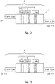
figure 1 , adrain system 1 in accordance with an embodiment of the invention comprises three distinct parts, A, B and C. Part A is that part of the drain which interfaces with the patient body by insertion into the body. This part may be several millimetres to a few centimetres long. Part B is the length of drain tube intermediate the patient's body and a flow meter provided as part C. Thedrain tube 2 is of a familiar type being formed from a medical grade silicone material having a diameter of 5 mm. Exudate is conducted from the patient by the drain to pass through part A, B and then through part C to be deposited into a collection vessel orbag 2. - Part A is shown in greater detail in
figure 2 . It includes a number of sensors SA1 to SAn located within a section of thedrain tube 2. In the figure, the drain tube containing the sensors is shown having a greater diameter than the inlet and outlet part of the tube but it will be appreciated that the diameter of the drain tube may, in alternative embodiments, be substantially the same. The sensors are connected to asensor bus 3 and from there to a processor. - Part B also includes a similar arrangement of sensors SB1 to SBn again connected to a
sensor bus 3 and to the processor. - The outputs from the sensors from parts A and B can be used to determine if there is a blockage along these sections of the drain by comparison of the respective flow rates as will be appreciated by a person skilled in the art without further elaboration.
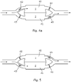
- Part C is formed of two or more tanks arranged in parallel and a valve arrangement for controlling the filling of the tanks as is shown in
figure 4 . They form branches in the drain though which the exudate may flow. Thetanks - Located at the entrance and exit of each tank is an
inlet valve outlet valve valves 42 to 45 are motorised valves operated by acontrol system 46. Thecontrol system 46 is microprocessor based operating in accordance with machine executable code stored in local memory. Its structure and method of operation will be later described. - Each of the
tanks sensors figure 1 . Each sensor can provide an output of the level of exudate within the tank as the exudate builds up (level increases). The sensors are connected to thecontrol system 46 over thesensor bus 3. - The
flow control system 46 monitors each of the sensors and determines if there is an abrupt change in flow conditions. If such is detected, a downstream flow obstruction check process is performed. In this, thevalves 42 to 45 are selectively opened and closed in a synchronised manner under the control of theflow control system 46 to determine the presence of an obstruction. This will be more fully described later after an overview of the system is given. - Reverting now to
figure 1 , thecontrol system 46 includes aprocessor 50, acomparator 51, aflow controller 52, amemory 53 and analarm 54. Thememory 53 is provided as a combination of Read Only Memory (ROM) and Random Access Memory (RAM) to hold data and a program as a set of executable code instructions to govern the system operation under theprocessor 50. - The
comparator 51 is connected to thesensor bus 3. It reads each of the sensors and performs a comparison to determine the respective flow rates throughout the parts A, B and C, and to deduce therefrom if there are any blockages. In the event that a blockage is determined then an output is provided to theprocessor 50 which instructs thealarm 54 to give an audible and visual alarm signal to warn nursing staff. - The
flow controller 52 is connected to avalve control bus 55 to provide control output to each of thevalves 42 to 45. The bus also allows status information for the valves to be passed back to the flow controller. Theflow controller 52 operates as instructed by theprocessor 50 to control the selection of the tanks to fill or empty in accordance with the predetermined scheme as referred to earlier by opening and closing valves in a synchronised manner. That is to say,valves valve 42 is openedvalve 44 is instructed to close and whenvalve 42 is instructed to close,valve 44 is instructed to open. Similarly, whenvalve 43 is instructed to open,valve 45 is instructed to close and whenvalve 43 is instructed to close,valve 45 is instructed to open. To fill a tank, the inlet valve is opened and the outlet valve is closed, that is to say,valves valves valves valves - In normal operation the tanks are opened and allowed to fill or closed and allowed to empty in an alternating manner. That is to say, when
tank 40 is to be filledtank 41 is to be emptied and vice versa. - In a first phase,
tank 40 is filled. To do thisvalve 45 is opened,valve 44 is closed andvalve 42 opened andvalve 43 closed. This is depicted infigure 4 . This causestank 40 to fill andtank 41 to empty. To allow this to occur a vent "V" is located in an upper position in the dividing wall "W" between the tanks to allow for air to flow between one tank and the other that would otherwise be trapped as is shown infigure 4b . - In a second phase, as depicted in
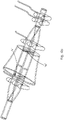
figure 5 ,tank 40 is full, and is to be emptied, andtank 41 is empty and is to be filled. Thecontrol system 46signals valve 45 to close andvalve 44 to open. At the same time,valve 42 is instructed to close andvalve 43 to open. - During this process, the control system monitors the signals of the tank sensors. In the event that the tanks do not empty or empty more slowly than the tank being filled then the
control system 46 determines that there is an obstruction downstream of the tanks. - The way in which the system operates will now be described with reference to
figures 6 and7 . - In a
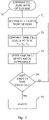
first step 60, the system initialises. This is carried out when the drain is inserted into the patient and the system is switched on by the medical staff. In this step the system "boots up" and performs checks on the various sensors and valves in the system to ensure that they are operational. The status of the system and its components may be indicated on a display to the staff. - In the
next step 61, the tank to be filled and the tank to be emptied are selected. In thiscase tank 40 is selected to be filled first and thetank 41 selected to be emptied. Accordingly, theflow controller 52 is instructed by theprocessor 50 to set the valves to the correct states.Valve 42 is opened to the forward part of the drain,valve 44 is closed andvalve 43 is closed to the forward part of the drain (but opened to atmosphere) andvalve 45 opened.Tank 40 then fills as the exudate is drained andtank 41 empties. - In
step 62, a period of time is allowed to elapse to allow the exudate flow to be established. - In
step 63, the fill level of the tank being filled is determined by thecomparator 51 polling the sensors within the tank. The sensor determines the level of the exudate in the tank. This is compared with a predetermined threshold held in memory instep 64 and the comparison repeated. If the threshold is reached, then the tank is considered to be full and the process progresses to step 65. - In
step 65 the tanks are switched to the alternative state. That is to say, the tank being filled is selected to be emptied and the tank being emptied is selected to be filled. Following the above,tank 40 is selected to be emptied andtank 41 is selected to be filled. To do this, flowcontroller 52 is instructed by theprocessor 50 to switch the valve states. That is to say,valve 42 is closed to the section B (but opened to atmosphere),valve 44 is opened to allow the exudate to flow out of thetank 40. Thevalve 43 oftank 41 is opened to section B (and closed to atmosphere) andvalve 45 is closed.Tank 41 then proceeds to fill. - The tank fill and emptying rates are then determined and stored in
memory 53 insteps processor 50 instructing thecomparator 51 to provide the outputs of the tank sensors. In this, the exudate levels are checked in the tanks at respective time intervals determined by a system clock (not shown). Thus, the stored states at the particular time intervals provide a rate of filling or emptying of the tanks. - In a
process 70 shown infigure 7 , theprocessor 50 accesses the stored data frommemory 53 instep 71. It then compares the fill levels at the time intervals instep 71, and instep 72, determines the rate of filling and the rate of emptying of the tanks. The average difference in the rate is determined instep 73. - In
step 74, the difference in the rate is compared with a predetermined threshold value held inmemory 53. If the threshold is not exceeded then the processor accesses the data from memory for the next tank state switching and repeatssteps 71 to 74. If the threshold is exceeded, then an alarm is issued instep 75 by suitable instruction from theprocessor 50 to thealarm device 54. - The medical staff will then be aware of the blockage and may take remedial action by replacing the drain, or parts of it, as required to clear or remove the blockage.
- As will be appreciated there will be a number of variations and combinations of features disclosed in the application which will fall within the scope of the recited claims.
Claims (13)
- A surgical drain for, in use, conducting exudate from a patient wound comprising a first branch (40) and a second branch (41); a flow controller (52) configured to, in use, control flow of the exudate through the branches and means to monitor the rate of flow therethrough; a comparator (51) to compare the respective rates of flow through the first and the second branch and to provide an output representative thereof, characterised in that the first and second branches are provided with respective input and output valves (42,43,44,45) to control the flow therethrough under the control of the flow controller, further comprising logic means to determine an alarm condition when one of the first or the second branch fills more quickly than the other of the first or second branch empties.
- A surgical drain as claimed in claim 1 comprising an alarm device responsive to the alarm condition.
- A surgical drain as claimed in anyone of claims 1 or 2 comprising level sensors within the branches to provide an output indicative of the level of exudate within the branch.
- A surgical drain as claimed in any preceding claim wherein the branches comprise tanks.
- A surgical drain as claimed in claim 4 wherein each tank has a nominally identical volume.
- A surgical drain as claimed in any preceding claim comprising an inlet section including exudate sensors for determining an exudate flow therethrough which inlet section including a portion configured for insertion, in use, into a patient.
- A surgical drain as claimed in claim 6 further comprising an intermediate portion connecting the inlet section to the first and second branches.
- A surgical drain as claimed in claim 7 further comprising sensors located in the intermediate portion to determine an exudate flow therethrough.
- A method of determining the presence of a blockage in a surgical drain having two or more branches comprising the steps of:filling a first branch with exudate to be drained;directing an exudate flow away from an input to the first branch to an input of a second branch in the drain to fill the second branch;directing an exudate flow from the first branch to an output from the drain to empty that branch;comparing the rate of filling of the second branch with the rate of emptying of the first branch to determine a blockage condition.
- A method as claimed in claim 9 comprising the step of providing an alarm when a blockage condition is determined.
- A method as claimed in claim 9 or 10 wherein the step of directing flow includes opening inlet and outlet valves controlling the flow within respective branches.
- A method as claimed in claim 9, 10 or 11 wherein the rate of filling and emptying is determine by reading level sensors determining the level of exudate in respective branches.
- A data carrier storing a set of computer implementable instructions for carrying out the method as claimed in any one of claims 9 to 12.
Priority Applications (3)
| Application Number | Priority Date | Filing Date | Title |
|---|---|---|---|
| EP17305602.9A EP3406273B1 (en) | 2017-05-23 | 2017-05-23 | A surgical drain |
| US15/968,028 US10953207B2 (en) | 2017-05-23 | 2018-05-01 | Surgical drain |
| US17/180,347 US20210178131A1 (en) | 2017-05-23 | 2021-02-19 | Surgical drain |
Applications Claiming Priority (1)
| Application Number | Priority Date | Filing Date | Title |
|---|---|---|---|
| EP17305602.9A EP3406273B1 (en) | 2017-05-23 | 2017-05-23 | A surgical drain |
Publications (2)
| Publication Number | Publication Date |
|---|---|
| EP3406273A1 EP3406273A1 (en) | 2018-11-28 |
| EP3406273B1 true EP3406273B1 (en) | 2022-03-30 |
Family
ID=59034666
Family Applications (1)
| Application Number | Title | Priority Date | Filing Date |
|---|---|---|---|
| EP17305602.9A Active EP3406273B1 (en) | 2017-05-23 | 2017-05-23 | A surgical drain |
Country Status (2)
| Country | Link |
|---|---|
| US (2) | US10953207B2 (en) |
| EP (1) | EP3406273B1 (en) |
Family Cites Families (5)
| Publication number | Priority date | Publication date | Assignee | Title |
|---|---|---|---|---|
| US7947033B2 (en) * | 1999-04-06 | 2011-05-24 | Kci Licensing Inc. | Systems and methods for detection of wound fluid blood and application of phototherapy in conjunction with reduced pressure wound treatment system |
| US9408954B2 (en) * | 2007-07-02 | 2016-08-09 | Smith & Nephew Plc | Systems and methods for controlling operation of negative pressure wound therapy apparatus |
| GB0723876D0 (en) * | 2007-12-06 | 2008-01-16 | Smith & Nephew | Apparatus and method for topical negative pressure therapy |
| WO2012078781A1 (en) * | 2010-12-08 | 2012-06-14 | Convatec Technologies Inc. | Integrated system for assessing wound exudates |
| TWI641397B (en) * | 2015-12-15 | 2018-11-21 | 雃博股份有限公司 | Pressure control method and system |
-
2017
- 2017-05-23 EP EP17305602.9A patent/EP3406273B1/en active Active
-
2018
- 2018-05-01 US US15/968,028 patent/US10953207B2/en active Active
-
2021
- 2021-02-19 US US17/180,347 patent/US20210178131A1/en active Pending
Also Published As
| Publication number | Publication date |
|---|---|
| US20180339140A1 (en) | 2018-11-29 |
| EP3406273A1 (en) | 2018-11-28 |
| US20210178131A1 (en) | 2021-06-17 |
| US10953207B2 (en) | 2021-03-23 |
Similar Documents
| Publication | Publication Date | Title |
|---|---|---|
| CA1057149A (en) | Apparatus for peritoneal dialysis | |
| TR201906109T4 (en) | Sensor system for detecting phases and / or phase transitions in peritoneal dialysis treatment. | |
| AU2019261792B2 (en) | Devices and methods for managing chest drainage | |
| JP6634661B2 (en) | Systems, instruments and methods for draining and analyzing body fluids | |
| EP2192937B1 (en) | An infusion apparatus | |
| CA2495561C (en) | Blood purifying device and method of operating the same | |
| JP4274699B2 (en) | Tubes and applications for extracorporeal blood purification | |
| EP2291207B1 (en) | A medical fluid circuit comprising a low level detector | |
| US8157775B2 (en) | Postoperative fluid monitoring and alert system | |
| EP2190497B1 (en) | Automated body fluid drain control apparatus | |
| US11420031B2 (en) | System and method for draining cerebrospinal fluid in hydrocephalus patients | |
| US11478751B2 (en) | Automated single-use filtering apparatus, and method for controlling an automated single-use filtering apparatus | |
| CN108778361A (en) | The method and system of the obstruction in blood circuit for detecting dialysis system | |
| EP3406273B1 (en) | A surgical drain | |
| EP2737918B1 (en) | Hemodialysis on-line port leak detection | |
| CN106267426A (en) | A kind of centrifugal separation sampled plasma device | |
| US20220370698A1 (en) | Autonomous dialysis control | |
| US11305043B2 (en) | Method for regulating a heating device for heating a fluid for a dialysis fluid circuity, control device and blood treatment apparatus | |
| CN117159836A (en) | Full lung lavage system | |
| JPS63222769A (en) | Body fluid control apparatus |
Legal Events
| Date | Code | Title | Description |
|---|---|---|---|
| PUAI | Public reference made under article 153(3) epc to a published international application that has entered the european phase |
Free format text: ORIGINAL CODE: 0009012 |
|
| STAA | Information on the status of an ep patent application or granted ep patent |
Free format text: STATUS: THE APPLICATION HAS BEEN PUBLISHED |
|
| AK | Designated contracting states |
Kind code of ref document: A1 Designated state(s): AL AT BE BG CH CY CZ DE DK EE ES FI FR GB GR HR HU IE IS IT LI LT LU LV MC MK MT NL NO PL PT RO RS SE SI SK SM TR |
|
| AX | Request for extension of the european patent |
Extension state: BA ME |
|
| STAA | Information on the status of an ep patent application or granted ep patent |
Free format text: STATUS: REQUEST FOR EXAMINATION WAS MADE |
|
| 17P | Request for examination filed |
Effective date: 20190521 |
|
| RBV | Designated contracting states (corrected) |
Designated state(s): AL AT BE BG CH CY CZ DE DK EE ES FI FR GB GR HR HU IE IS IT LI LT LU LV MC MK MT NL NO PL PT RO RS SE SI SK SM TR |
|
| GRAP | Despatch of communication of intention to grant a patent |
Free format text: ORIGINAL CODE: EPIDOSNIGR1 |
|
| STAA | Information on the status of an ep patent application or granted ep patent |
Free format text: STATUS: GRANT OF PATENT IS INTENDED |
|
| INTG | Intention to grant announced |
Effective date: 20211021 |
|
| GRAS | Grant fee paid |
Free format text: ORIGINAL CODE: EPIDOSNIGR3 |
|
| GRAA | (expected) grant |
Free format text: ORIGINAL CODE: 0009210 |
|
| STAA | Information on the status of an ep patent application or granted ep patent |
Free format text: STATUS: THE PATENT HAS BEEN GRANTED |
|
| AK | Designated contracting states |
Kind code of ref document: B1 Designated state(s): AL AT BE BG CH CY CZ DE DK EE ES FI FR GB GR HR HU IE IS IT LI LT LU LV MC MK MT NL NO PL PT RO RS SE SI SK SM TR |
|
| REG | Reference to a national code |
Ref country code: GB Ref legal event code: FG4D |
|
| REG | Reference to a national code |
Ref country code: CH Ref legal event code: EP |
|
| REG | Reference to a national code |
Ref country code: AT Ref legal event code: REF Ref document number: 1478577 Country of ref document: AT Kind code of ref document: T Effective date: 20220415 |
|
| REG | Reference to a national code |
Ref country code: DE Ref legal event code: R096 Ref document number: 602017055154 Country of ref document: DE |
|
| REG | Reference to a national code |
Ref country code: IE Ref legal event code: FG4D |
|
| REG | Reference to a national code |
Ref country code: LT Ref legal event code: MG9D |
|
| PG25 | Lapsed in a contracting state [announced via postgrant information from national office to epo] |
Ref country code: SE Free format text: LAPSE BECAUSE OF FAILURE TO SUBMIT A TRANSLATION OF THE DESCRIPTION OR TO PAY THE FEE WITHIN THE PRESCRIBED TIME-LIMIT Effective date: 20220330 Ref country code: RS Free format text: LAPSE BECAUSE OF FAILURE TO SUBMIT A TRANSLATION OF THE DESCRIPTION OR TO PAY THE FEE WITHIN THE PRESCRIBED TIME-LIMIT Effective date: 20220330 Ref country code: NO Free format text: LAPSE BECAUSE OF FAILURE TO SUBMIT A TRANSLATION OF THE DESCRIPTION OR TO PAY THE FEE WITHIN THE PRESCRIBED TIME-LIMIT Effective date: 20220630 Ref country code: LT Free format text: LAPSE BECAUSE OF FAILURE TO SUBMIT A TRANSLATION OF THE DESCRIPTION OR TO PAY THE FEE WITHIN THE PRESCRIBED TIME-LIMIT Effective date: 20220330 Ref country code: HR Free format text: LAPSE BECAUSE OF FAILURE TO SUBMIT A TRANSLATION OF THE DESCRIPTION OR TO PAY THE FEE WITHIN THE PRESCRIBED TIME-LIMIT Effective date: 20220330 Ref country code: BG Free format text: LAPSE BECAUSE OF FAILURE TO SUBMIT A TRANSLATION OF THE DESCRIPTION OR TO PAY THE FEE WITHIN THE PRESCRIBED TIME-LIMIT Effective date: 20220630 |
|
| REG | Reference to a national code |
Ref country code: NL Ref legal event code: MP Effective date: 20220330 |
|
| REG | Reference to a national code |
Ref country code: AT Ref legal event code: MK05 Ref document number: 1478577 Country of ref document: AT Kind code of ref document: T Effective date: 20220330 |
|
| PG25 | Lapsed in a contracting state [announced via postgrant information from national office to epo] |
Ref country code: LV Free format text: LAPSE BECAUSE OF FAILURE TO SUBMIT A TRANSLATION OF THE DESCRIPTION OR TO PAY THE FEE WITHIN THE PRESCRIBED TIME-LIMIT Effective date: 20220330 Ref country code: GR Free format text: LAPSE BECAUSE OF FAILURE TO SUBMIT A TRANSLATION OF THE DESCRIPTION OR TO PAY THE FEE WITHIN THE PRESCRIBED TIME-LIMIT Effective date: 20220701 Ref country code: FI Free format text: LAPSE BECAUSE OF FAILURE TO SUBMIT A TRANSLATION OF THE DESCRIPTION OR TO PAY THE FEE WITHIN THE PRESCRIBED TIME-LIMIT Effective date: 20220330 |
|
| PG25 | Lapsed in a contracting state [announced via postgrant information from national office to epo] |
Ref country code: NL Free format text: LAPSE BECAUSE OF FAILURE TO SUBMIT A TRANSLATION OF THE DESCRIPTION OR TO PAY THE FEE WITHIN THE PRESCRIBED TIME-LIMIT Effective date: 20220330 |
|
| PG25 | Lapsed in a contracting state [announced via postgrant information from national office to epo] |
Ref country code: SM Free format text: LAPSE BECAUSE OF FAILURE TO SUBMIT A TRANSLATION OF THE DESCRIPTION OR TO PAY THE FEE WITHIN THE PRESCRIBED TIME-LIMIT Effective date: 20220330 Ref country code: SK Free format text: LAPSE BECAUSE OF FAILURE TO SUBMIT A TRANSLATION OF THE DESCRIPTION OR TO PAY THE FEE WITHIN THE PRESCRIBED TIME-LIMIT Effective date: 20220330 Ref country code: RO Free format text: LAPSE BECAUSE OF FAILURE TO SUBMIT A TRANSLATION OF THE DESCRIPTION OR TO PAY THE FEE WITHIN THE PRESCRIBED TIME-LIMIT Effective date: 20220330 Ref country code: PT Free format text: LAPSE BECAUSE OF FAILURE TO SUBMIT A TRANSLATION OF THE DESCRIPTION OR TO PAY THE FEE WITHIN THE PRESCRIBED TIME-LIMIT Effective date: 20220801 Ref country code: ES Free format text: LAPSE BECAUSE OF FAILURE TO SUBMIT A TRANSLATION OF THE DESCRIPTION OR TO PAY THE FEE WITHIN THE PRESCRIBED TIME-LIMIT Effective date: 20220330 Ref country code: EE Free format text: LAPSE BECAUSE OF FAILURE TO SUBMIT A TRANSLATION OF THE DESCRIPTION OR TO PAY THE FEE WITHIN THE PRESCRIBED TIME-LIMIT Effective date: 20220330 Ref country code: CZ Free format text: LAPSE BECAUSE OF FAILURE TO SUBMIT A TRANSLATION OF THE DESCRIPTION OR TO PAY THE FEE WITHIN THE PRESCRIBED TIME-LIMIT Effective date: 20220330 Ref country code: AT Free format text: LAPSE BECAUSE OF FAILURE TO SUBMIT A TRANSLATION OF THE DESCRIPTION OR TO PAY THE FEE WITHIN THE PRESCRIBED TIME-LIMIT Effective date: 20220330 |
|
| PG25 | Lapsed in a contracting state [announced via postgrant information from national office to epo] |
Ref country code: PL Free format text: LAPSE BECAUSE OF FAILURE TO SUBMIT A TRANSLATION OF THE DESCRIPTION OR TO PAY THE FEE WITHIN THE PRESCRIBED TIME-LIMIT Effective date: 20220330 Ref country code: IS Free format text: LAPSE BECAUSE OF FAILURE TO SUBMIT A TRANSLATION OF THE DESCRIPTION OR TO PAY THE FEE WITHIN THE PRESCRIBED TIME-LIMIT Effective date: 20220730 Ref country code: AL Free format text: LAPSE BECAUSE OF FAILURE TO SUBMIT A TRANSLATION OF THE DESCRIPTION OR TO PAY THE FEE WITHIN THE PRESCRIBED TIME-LIMIT Effective date: 20220330 |
|
| REG | Reference to a national code |
Ref country code: CH Ref legal event code: PL |
|
| REG | Reference to a national code |
Ref country code: DE Ref legal event code: R097 Ref document number: 602017055154 Country of ref document: DE |
|
| REG | Reference to a national code |
Ref country code: BE Ref legal event code: MM Effective date: 20220531 |
|
| PG25 | Lapsed in a contracting state [announced via postgrant information from national office to epo] |
Ref country code: MC Free format text: LAPSE BECAUSE OF FAILURE TO SUBMIT A TRANSLATION OF THE DESCRIPTION OR TO PAY THE FEE WITHIN THE PRESCRIBED TIME-LIMIT Effective date: 20220330 Ref country code: LU Free format text: LAPSE BECAUSE OF NON-PAYMENT OF DUE FEES Effective date: 20220523 Ref country code: LI Free format text: LAPSE BECAUSE OF NON-PAYMENT OF DUE FEES Effective date: 20220531 Ref country code: DK Free format text: LAPSE BECAUSE OF FAILURE TO SUBMIT A TRANSLATION OF THE DESCRIPTION OR TO PAY THE FEE WITHIN THE PRESCRIBED TIME-LIMIT Effective date: 20220330 Ref country code: CH Free format text: LAPSE BECAUSE OF NON-PAYMENT OF DUE FEES Effective date: 20220531 |
|
| PLBE | No opposition filed within time limit |
Free format text: ORIGINAL CODE: 0009261 |
|
| STAA | Information on the status of an ep patent application or granted ep patent |
Free format text: STATUS: NO OPPOSITION FILED WITHIN TIME LIMIT |
|
| 26N | No opposition filed |
Effective date: 20230103 |
|
| PG25 | Lapsed in a contracting state [announced via postgrant information from national office to epo] |
Ref country code: IE Free format text: LAPSE BECAUSE OF NON-PAYMENT OF DUE FEES Effective date: 20220523 |
|
| PG25 | Lapsed in a contracting state [announced via postgrant information from national office to epo] |
Ref country code: SI Free format text: LAPSE BECAUSE OF FAILURE TO SUBMIT A TRANSLATION OF THE DESCRIPTION OR TO PAY THE FEE WITHIN THE PRESCRIBED TIME-LIMIT Effective date: 20220330 Ref country code: BE Free format text: LAPSE BECAUSE OF NON-PAYMENT OF DUE FEES Effective date: 20220531 |
|
| PG25 | Lapsed in a contracting state [announced via postgrant information from national office to epo] |
Ref country code: IT Free format text: LAPSE BECAUSE OF FAILURE TO SUBMIT A TRANSLATION OF THE DESCRIPTION OR TO PAY THE FEE WITHIN THE PRESCRIBED TIME-LIMIT Effective date: 20220330 |
|
| PGFP | Annual fee paid to national office [announced via postgrant information from national office to epo] |
Ref country code: FR Payment date: 20230420 Year of fee payment: 7 Ref country code: DE Payment date: 20230419 Year of fee payment: 7 |
|
| PGFP | Annual fee paid to national office [announced via postgrant information from national office to epo] |
Ref country code: GB Payment date: 20230420 Year of fee payment: 7 |
|
| PG25 | Lapsed in a contracting state [announced via postgrant information from national office to epo] |
Ref country code: HU Free format text: LAPSE BECAUSE OF FAILURE TO SUBMIT A TRANSLATION OF THE DESCRIPTION OR TO PAY THE FEE WITHIN THE PRESCRIBED TIME-LIMIT; INVALID AB INITIO Effective date: 20170523 |
|
| PG25 | Lapsed in a contracting state [announced via postgrant information from national office to epo] |
Ref country code: MK Free format text: LAPSE BECAUSE OF FAILURE TO SUBMIT A TRANSLATION OF THE DESCRIPTION OR TO PAY THE FEE WITHIN THE PRESCRIBED TIME-LIMIT Effective date: 20220330 Ref country code: CY Free format text: LAPSE BECAUSE OF FAILURE TO SUBMIT A TRANSLATION OF THE DESCRIPTION OR TO PAY THE FEE WITHIN THE PRESCRIBED TIME-LIMIT Effective date: 20220330 |