EP3373433B1 - A photovoltaic power plant system - Google Patents
A photovoltaic power plant system Download PDFInfo
- Publication number
- EP3373433B1 EP3373433B1 EP17159484.9A EP17159484A EP3373433B1 EP 3373433 B1 EP3373433 B1 EP 3373433B1 EP 17159484 A EP17159484 A EP 17159484A EP 3373433 B1 EP3373433 B1 EP 3373433B1
- Authority
- EP
- European Patent Office
- Prior art keywords
- converter
- power plant
- photovoltaic
- converters
- plant system
- Prior art date
- Legal status (The legal status is an assumption and is not a legal conclusion. Google has not performed a legal analysis and makes no representation as to the accuracy of the status listed.)
- Active
Links
- 230000005540 biological transmission Effects 0.000 claims description 13
- 238000010248 power generation Methods 0.000 claims description 5
- 238000000034 method Methods 0.000 description 9
- 238000003491 array Methods 0.000 description 7
- 238000013461 design Methods 0.000 description 7
- 230000002776 aggregation Effects 0.000 description 6
- 238000004220 aggregation Methods 0.000 description 6
- 238000011161 development Methods 0.000 description 4
- 230000018109 developmental process Effects 0.000 description 4
- 239000004020 conductor Substances 0.000 description 2
- 238000010586 diagram Methods 0.000 description 2
- 238000005516 engineering process Methods 0.000 description 2
- 238000012423 maintenance Methods 0.000 description 2
- 238000012544 monitoring process Methods 0.000 description 2
- 230000033228 biological regulation Effects 0.000 description 1
- 239000003990 capacitor Substances 0.000 description 1
- 238000006243 chemical reaction Methods 0.000 description 1
- 230000007423 decrease Effects 0.000 description 1
- 230000003247 decreasing effect Effects 0.000 description 1
- 230000001419 dependent effect Effects 0.000 description 1
- 230000005611 electricity Effects 0.000 description 1
- 230000007613 environmental effect Effects 0.000 description 1
- 239000000446 fuel Substances 0.000 description 1
- 238000002955 isolation Methods 0.000 description 1
- 230000001105 regulatory effect Effects 0.000 description 1
- 230000009466 transformation Effects 0.000 description 1
Images

Classifications
-
- H—ELECTRICITY
- H02—GENERATION; CONVERSION OR DISTRIBUTION OF ELECTRIC POWER
- H02M—APPARATUS FOR CONVERSION BETWEEN AC AND AC, BETWEEN AC AND DC, OR BETWEEN DC AND DC, AND FOR USE WITH MAINS OR SIMILAR POWER SUPPLY SYSTEMS; CONVERSION OF DC OR AC INPUT POWER INTO SURGE OUTPUT POWER; CONTROL OR REGULATION THEREOF
- H02M3/00—Conversion of dc power input into dc power output
- H02M3/02—Conversion of dc power input into dc power output without intermediate conversion into ac
- H02M3/04—Conversion of dc power input into dc power output without intermediate conversion into ac by static converters
- H02M3/10—Conversion of dc power input into dc power output without intermediate conversion into ac by static converters using discharge tubes with control electrode or semiconductor devices with control electrode
- H02M3/145—Conversion of dc power input into dc power output without intermediate conversion into ac by static converters using discharge tubes with control electrode or semiconductor devices with control electrode using devices of a triode or transistor type requiring continuous application of a control signal
- H02M3/155—Conversion of dc power input into dc power output without intermediate conversion into ac by static converters using discharge tubes with control electrode or semiconductor devices with control electrode using devices of a triode or transistor type requiring continuous application of a control signal using semiconductor devices only
- H02M3/156—Conversion of dc power input into dc power output without intermediate conversion into ac by static converters using discharge tubes with control electrode or semiconductor devices with control electrode using devices of a triode or transistor type requiring continuous application of a control signal using semiconductor devices only with automatic control of output voltage or current, e.g. switching regulators
- H02M3/158—Conversion of dc power input into dc power output without intermediate conversion into ac by static converters using discharge tubes with control electrode or semiconductor devices with control electrode using devices of a triode or transistor type requiring continuous application of a control signal using semiconductor devices only with automatic control of output voltage or current, e.g. switching regulators including plural semiconductor devices as final control devices for a single load
- H02M3/1584—Conversion of dc power input into dc power output without intermediate conversion into ac by static converters using discharge tubes with control electrode or semiconductor devices with control electrode using devices of a triode or transistor type requiring continuous application of a control signal using semiconductor devices only with automatic control of output voltage or current, e.g. switching regulators including plural semiconductor devices as final control devices for a single load with a plurality of power processing stages connected in parallel
-
- H—ELECTRICITY
- H02—GENERATION; CONVERSION OR DISTRIBUTION OF ELECTRIC POWER
- H02J—CIRCUIT ARRANGEMENTS OR SYSTEMS FOR SUPPLYING OR DISTRIBUTING ELECTRIC POWER; SYSTEMS FOR STORING ELECTRIC ENERGY
- H02J3/00—Circuit arrangements for ac mains or ac distribution networks
- H02J3/38—Arrangements for parallely feeding a single network by two or more generators, converters or transformers
- H02J3/381—Dispersed generators
-
- H—ELECTRICITY
- H02—GENERATION; CONVERSION OR DISTRIBUTION OF ELECTRIC POWER
- H02J—CIRCUIT ARRANGEMENTS OR SYSTEMS FOR SUPPLYING OR DISTRIBUTING ELECTRIC POWER; SYSTEMS FOR STORING ELECTRIC ENERGY
- H02J3/00—Circuit arrangements for ac mains or ac distribution networks
- H02J3/38—Arrangements for parallely feeding a single network by two or more generators, converters or transformers
- H02J3/46—Controlling of the sharing of output between the generators, converters, or transformers
-
- H—ELECTRICITY
- H02—GENERATION; CONVERSION OR DISTRIBUTION OF ELECTRIC POWER
- H02M—APPARATUS FOR CONVERSION BETWEEN AC AND AC, BETWEEN AC AND DC, OR BETWEEN DC AND DC, AND FOR USE WITH MAINS OR SIMILAR POWER SUPPLY SYSTEMS; CONVERSION OF DC OR AC INPUT POWER INTO SURGE OUTPUT POWER; CONTROL OR REGULATION THEREOF
- H02M7/00—Conversion of ac power input into dc power output; Conversion of dc power input into ac power output
- H02M7/42—Conversion of dc power input into ac power output without possibility of reversal
- H02M7/44—Conversion of dc power input into ac power output without possibility of reversal by static converters
- H02M7/48—Conversion of dc power input into ac power output without possibility of reversal by static converters using discharge tubes with control electrode or semiconductor devices with control electrode
- H02M7/483—Converters with outputs that each can have more than two voltages levels
- H02M7/4835—Converters with outputs that each can have more than two voltages levels comprising two or more cells, each including a switchable capacitor, the capacitors having a nominal charge voltage which corresponds to a given fraction of the input voltage, and the capacitors being selectively connected in series to determine the instantaneous output voltage
-
- H—ELECTRICITY
- H02—GENERATION; CONVERSION OR DISTRIBUTION OF ELECTRIC POWER
- H02S—GENERATION OF ELECTRIC POWER BY CONVERSION OF INFRARED RADIATION, VISIBLE LIGHT OR ULTRAVIOLET LIGHT, e.g. USING PHOTOVOLTAIC [PV] MODULES
- H02S40/00—Components or accessories in combination with PV modules, not provided for in groups H02S10/00 - H02S30/00
- H02S40/30—Electrical components
- H02S40/32—Electrical components comprising DC/AC inverter means associated with the PV module itself, e.g. AC modules
-
- H—ELECTRICITY
- H02—GENERATION; CONVERSION OR DISTRIBUTION OF ELECTRIC POWER
- H02J—CIRCUIT ARRANGEMENTS OR SYSTEMS FOR SUPPLYING OR DISTRIBUTING ELECTRIC POWER; SYSTEMS FOR STORING ELECTRIC ENERGY
- H02J2300/00—Systems for supplying or distributing electric power characterised by decentralized, dispersed, or local generation
- H02J2300/20—The dispersed energy generation being of renewable origin
- H02J2300/22—The renewable source being solar energy
- H02J2300/24—The renewable source being solar energy of photovoltaic origin
- H02J2300/26—The renewable source being solar energy of photovoltaic origin involving maximum power point tracking control for photovoltaic sources
-
- H—ELECTRICITY
- H02—GENERATION; CONVERSION OR DISTRIBUTION OF ELECTRIC POWER
- H02M—APPARATUS FOR CONVERSION BETWEEN AC AND AC, BETWEEN AC AND DC, OR BETWEEN DC AND DC, AND FOR USE WITH MAINS OR SIMILAR POWER SUPPLY SYSTEMS; CONVERSION OF DC OR AC INPUT POWER INTO SURGE OUTPUT POWER; CONTROL OR REGULATION THEREOF
- H02M7/00—Conversion of ac power input into dc power output; Conversion of dc power input into ac power output
- H02M7/42—Conversion of dc power input into ac power output without possibility of reversal
- H02M7/44—Conversion of dc power input into ac power output without possibility of reversal by static converters
Definitions
- the technology disclosed herein relates generally to the field of solar power generation, and in particular to a photovoltaic power plant system for power generation.
- PV photovoltaic
- PV power systems as with other renewables, are that they have low operating cost owing to free "fuel”.
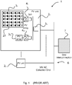
- FIG. 1 illustrates a simplified typical configuration for a PV power plant 1.
- a number of PV units 2 1 ,..., 2 n are grouped together.
- the size of a PV unit 2 1 ,..., 2 n as shown in figure 1 is up to 5 MW.
- Each PV unit 2 1 ,..., 2 n comprises a number of PV arrays 3 1 ,..., 3 m , each such array comprising a number of PV cells.
- Each PV array 3 1 ,..., 3 m is connected to a respective of direct current/alternating current (DC/AC) inverter 4 1 ,..., 4 m .
- DC/AC direct current/alternating current
- the DC/AC inverters 4 1 ,..., 4 m convert the DC electric power to an AC power, which is then stepped up by step-up transformers 5 k .
- the output from the step-up transformers 5 k is applied to a medium voltage AC collection grid 6, which may connect directly to a power substation 7 which in turn connects to a utility grid.
- the voltage of the AC collection grid 6 is usually at standardized Medium Voltage (MV) levels, for instance, 20 kV or 33 kV.
- MV Medium Voltage
- CN 104 113 082 A discloses a modular full direct current photovoltaic system and a control method thereof.
- the system comprises n DC-DC converter modules and an MMC centralized inverter, and every DC-DC converter module is connected with an independent control loop and a maximum power tracking control function so as to ensure that a photovoltaic battery pack connected with every DC-DC converter works on the highest point of the output power.
- EP 2 089 913 A2 discloses monitoring system and method for monitoring performance of individual powers sources in a distributed power source system.
- US 2016/099572 A1 discloses a system for extracting a medium DC voltage from a plurality of PV modules arranged in an array and supplying the medium DC voltage to inverters located outside the array near a point of interconnection with a utility grid.
- EP 2 533 412 A2 discloses a solar power conversion apparatus which includes at least one solar array receiving light and generating a DC power, a converter unit converting amplitude of the generated DC power, a multilevel inverter unit receiving the DC power from the converter unit to output AC power with multi levels and comprising a plurality of multilevel inverters, an AC filter insulating the inverter unit from a power grid, and a control unit applying a control signal to the converter unit and the multilevel inverter.
- US 2014/265584 A1 discloses a method and apparatus that can monitor the solar power inverters in real-time both day and night, and generate surveillance alarms and actions when a solar power inverter is removed or disconnected from the AC powerline for unknown reasons. It offers a low cost and reliable surveillance means to help guard a residential-scale, commercial-scale, or utility-scale solar power system in real-time at all times.
- US 2016/172838 A1 discloses a distribution manager for a power microgrid system includes a main bus, and a circuit breaker coupled to the main bus and to one of a load and an inter-microgrid connection system of the power microgrid system, the circuit breaker being structured to operate based on a set of functional trip settings.
- WO2016/009047 A1 discloses converter system for interconnecting renewable energy sources with a DC distribution bus comprises a converter unit which comprises an isolated DC-to-DC converter connectable to the renewable energy source, and a non-isolated DC-to-DC converter connectable to the DC distribution bus, which is cascade connected with the isolated DC-to-DC converter.
- EP 2 518 855 A2 discloses a distributed photovoltaic power plant which includes a plurality of distributed dc-dc converters.
- the dc-dc converters are configured to switch in coordination with one another such that at least one dc-dc converter transfers power to a common dc-bus based upon the total system power available from one or more corresponding strings of PV modules. Due to the coordinated switching of the dc-dc converters, each dc-dc converter transferring power to the common dc-bus continues to operate within its optimal efficiency range as well as to optimize the maximum power point tracking in order to increase the energy yield of the PV power plant.
- US 9 136 710 B1 discloses a method for converting power from a photovoltaic panel having substrings of PV cells. The method includes converting power from a first substring of the PV panel to generate a first DC output having a fixed portion and a variable portion, converting power from a second substring of the PV panel to generate a second DC output having a fixed portion and a variable portion, and combining the first and second DC outputs to generate a combined DC output.
- An objective of the present invention is to provide a photovoltaic power plant system for which the total cost can be reduced compared to prior art.
- a particular objective is to reduce the amount of cables.
- Another particular objective is to reduce the losses of the total photovoltaic power plant system.
- the objective is according to an aspect achieved by a photovoltaic power plant system for power generation.
- the photovoltaic power plant system comprises one or more photovoltaic clusters and one or more modular multilevel converters (MMC).
- MMC modular multilevel converters
- Each of the one or more photovoltaic clusters comprises a number of photovoltaic strings connected to one or more maximum power point tracking (MPPT) direct current/direct current (DC/DC) converters via a combiner box.
- MPPT maximum power point tracking
- DC/DC direct current/direct current
- the combiner box electrically combines the output from the photovoltaic strings.
- the one or more MPPT DC/DC converters comprises one or more inputs at low voltage level connected to the photovoltaic strings via the combiner box, and an output connected to a common DC low voltage (LV) bus.
- LV DC low voltage
- Each of the one or more photovoltaic clusters comprises a DC/DC converter comprising an input connected to the LVDC bus, and an output connected to a medium voltage DC (MVDC) collection grid.
- Each of the one or more MMCs comprises an input connected to the one or more photovoltaic clusters via the MVDC collection grid and an output connected to a transmission grid.
- the photovoltaic power plant system provides a number of advantages. For instance, from the low voltage DC level of the PV panel cabling the voltage is raised directly to MV level using a DC/DC converter station (comprising the MPPT DC/DC converters and the DC/DC converter) having multiple inputs from combiner boxes. Each DC/DC converter can then be connected in parallel with other DC/DC converters using the MVDC collection grid in different possible configurations.
- the use of DC/DC converters obviates the need for small distribution transformers, hence reducing cost and footprint. Further, no primary AC cabling at all is needed in the photovoltaic power plant system according to the invention, which enables a cost saving at deployment and also maintenance costs.
- an MMC provides the advantage of being fully controllable, and may thus be used to control the voltage at the MV collection grid.
- the MMC may also be used in fault handling of faults occurring in the photovoltaic clusters.
- the MMC enables the use of more cost-efficient disconnectors instead of DC breakers that have to be used in known photovoltaic power plant systems.
- the one or more MMCs are connected to the transmission grid via one or more parallel connected transformers for raising the output alternating current (AC) voltage to a level of the transmission grid.
- AC alternating current
- the DC/DC converter comprises a number of galvanically isolated converter cells connected in parallel at their input to the common LVDC bus, and in series at their output for increasing the output voltage to a MV level.
- the converter cells are unidirectional, allowing power flow only in the direction from the PV strings to the MVDC collection grid in a fixed voltage ratio, using a medium frequency transformer. Medium frequency transformers may be used to obtain galvanic isolation of the DC/DC converter cells.
- the rectifier part of the DC/DC converter cell comprises a diode rectifier.
- the DC/DC converter used in the photovoltaic power plant system is passive and the voltage of the MVDC collection grid is controlled entirely by the modular multilevel converter.
- the DC voltage is raised by the DC/DC converter cells of the DC/DC converter being series-connected.
- the medium frequency transformer may thereby have a voltage ratio close to 1:1 that makes the design more effective.
- the one or more DC/DC converters of the MVDC collection grid are arranged in a ring-bus configuration.
- the one or more DC/DC converters of the MVDC collection grid are arranged in a daisy-chain bus configuration.
- the above two sets of embodiments provide different advantages.
- the ring-bus configuration has a higher reliability compared to the daisy-chain bus configuration, but the daisy-chain configuration has reduced costs compared to the ring-bus configuration.
- the one or more MMCs are arranged at a common location.
- the placement of the one or more MMCs at a single location, at the point of interconnection (POI) to the transmission grid, enables an easier fulfillment of grid code requirements than for systems having many dispersed central inverters.
- the use of MMC may be used for providing reactive power to the grid, hence still further facilitating fulfilment of the grid code requirements, e.g. in case of grid faults.
- the one or more MMCs comprises full-bridge converter cells.
- the one or more MMCs comprises a mix of full-bridge converter cells and half-bridge converter cells. Such embodiments reduce the cost of the photovoltaic plant system since half-bridges cost less than full-bridge converter cells. In order to be able to properly handle faults on the AC bus and on the DC bus, approximately 1 ⁇ 4 of the full-bridges may be replaced by half-bridges in each of the MMC arms.
- the invention gives reduced costs for the complete photovoltaic power plant system. For instance, no bulky low-frequency transformers are needed, since they are replaced with much smaller medium frequency transformers in the DC/DC converters. Fewer cables at MV level are needed, and no reactive power compensation is needed since a DC collection grid is used. Further, the invention enables potential for higher efficiencies owing to the MVDC collection grid, which entails lower losses. This gives a flexible and modular design. Further still, AC cables have three conductors, while DC cables have two, and the use of a DC collection grid thereby also reduces the cost of cabling compared to the use of AC collection grid.
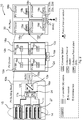
- FIG. 2 illustrates a general design of a photovoltaic (PV) power plant according to the invention, showing three main stages 12a, 18a, 20 of power aggregation therein.
- PV photovoltaic
- a number of PV modules 27 are interconnected (in particular connected in series) in order to reach a desired voltage level, for instance up to about 1.5kV.
- Each PV module 27 comprises a number of series- and/or parallel-connected solar cells (also denoted photovoltaic cells) for converting energy of light into electricity.
- the PV modules 27 form a number of PV strings 14 and groups of PV strings 14 are then interconnected to a respective combiner box 11.
- Several such combiner boxes may be provided, each electrically combining the output from PV strings 14 of a group.
- the PV strings 14 are shown to be connected in parallel. From the combiner boxes 11 the power is fed to a converter station (CS) 16a with one pair of cables, in contrast to the prior art solution illustrated in figure 1 , where the power is fed to a central inverter.
- CS converter station
- the PV strings 14 form a PV array 15, the combiner boxes 11 and the converter station 16a together form a PV Building Block (BB) 12a, i.e. the first power aggregation stage 12a.
- the converter station 16a may comprise a number of maximum power point tracking (MPPT) DC/DC converters 17a and a DC/DC converter 13a.
- MPPT maximum power point tracking
- the converter station 16a has one or multiple inputs (left hand side in the figure 2 ) at low voltage (LV) level in order to connect to the PV arrays 14 via the combiner boxes 11, and one output at MV level (right hand side in the figure 2 ) in order to connect to a MVDC collection grid (as part of a second power aggregation stage, described later), which has a collection point 19a for PV clusters 18a, 18b, 18c, 18d.
- the DC/DC converter 13a of the converter station 16a may comprise a number of galvanically isolated converter cells connected in parallel at their input, i.e. at the common LVDC bus 24, and in series at their output in order to increase the voltage to the required MV level. In the specific example illustrated in figure 2 , these converter cells are unidirectional, allowing power flow only in the direction from the PV arrays 15 to the MVDC collection grid in a fixed voltage ratio.
- the MPPT DC/DC converter 17a may comprise one large or several smaller MPPT converters. In case of several smaller MPPT converters each of them is connected to one or more PV strings 14 via the combiner boxes 11.
- the MPPT converter 17a may be a simple boost converter that controls the input DC current from the combiner box 11 to obtain the maximum energy from the PV modules. Its output is connected to a common LVDC voltage bus that is varied according to the MVDC voltage in order to inject the available generation power coming from the PV arrays 15.
- the voltage of the LVDC bus is a bit higher than the voltage at the PV arrays 15.
- a number of PV BBs 12a, 12b, 12c, 12d are, as indicated above, connected in series and form a PV cluster 18a.
- Each PV cluster 18a, 18b, 18c, 18d is then connected to a dedicated DC/AC inverter 22a, 22b, 22c, 22d.
- the DC/AC inverter 22a, 22b, 22c, 22d may, for instance, comprise a modular multilevel converter (MMC, described more in detail later e.g. in relation to figure 6 ).
- MMC modular multilevel converter
- the dedicated DC/AC inverter 22a, 22b, 22c, 22d for each PV cluster 18a, 18b, 18c, 18d, but a single MMC 22a, 22b, 22c, 22d may be used in some embodiments.
- the dedicated DC/AC inverter 22a, 22b, 22c, 22d in the following exemplified by the MMC 22; 22a, 22b, 22c, 22d, is situated at a collection point of plant (CPP) 21.
- the MVDC collection grid can be configured in various different ways, for example as a star (daisy-chain) or a ring configuration (for increased availability), as described more in detail later with reference to figures 5a and 5b .
- the voltage can be in the range of ⁇ 5kV to ⁇ 30kV.
- the MMCs 22a, 22b, 22c, 22d are parallelized in their output, reaching the power of the total PV power plant system 10.
- Main components of the collection point of the plant are the DC/AC inverters 22a, 22b, 22c, 22d, preferably (as mentioned) one for each PV cluster 18a, 18b, 18c, 18d.
- one single DC/AC inverter 22a, 22b, 22c, 22d may take care of the energy generated by more than one PV cluster 18a, 18b, 18c, 18d.
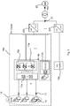
- Figure 3 is a simplified single line diagram of high-level PV power plant system 10 according to the present invention.
- the converter station 16a is a key component of the solar PV power plant system 10 and comprises one or more MPPT DC/DC converters 17a, a number of inputs for the various PV strings 14, the DC/DC converter 13a that will raise the voltage from LV to MV level. Further, there may additionally also be protection devices, LV and MV switchgear and other auxiliaries. At its output (i.e. the output from the DC/DC converter 13a) the converter station 16a has four terminals, two at negative potential (e.g. -10kV) and two at positive potential (e.g. +10kV) for connecting to the MVDC bus.
- MPPT DC/DC converters 17a a number of inputs for the various PV strings 14, the DC/DC converter 13a that will raise the voltage from LV to MV level. Further, there may additionally also be protection devices, LV and MV switchgear and other auxiliaries.
- the converter station 16a At its output (i.e. the output from the DC/DC converter 13a) the converter station 16a
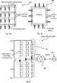
- FIG. 4 illustrates an embodiment of a converter station for use in the PV power plant according to the invention.
- a MPPT converter block 25 comprises four MPPT DC/DC converters 17a, 17b, 17c, 17d.
- the number of MPPT DC/DC converters 17a, 17b, 17c, 17d may be adapted: more converters will extract more energy from the PV arrays but will also increase the total cost.
- the input voltage may, for instance, be below 1.5kV (from the PV array) and the common LVDC bus 24 at the output of the MVDC converter block 25 may be at least 1.5kV.
- the DC/DC converter 13a may comprise a number of DC/DC converter cells that are connected at their input in parallel to the LVDC bus 24 and at their output in series raising the voltage to MV level.
- the MV bus in this embodiment is ⁇ 10kV, although this value may vary depending on the transformation ratio of a medium frequency transformer (MFT) in the DC/DC converter cells and on the number of such cells connected in series.
- MFT medium frequency transformer
- the converter station 16a may also comprise LV breakers at the input of the MPPT block, as well as a number of MV AC disconnectors at the output.
- the MPPT converter block 25 is a part of the converter station 16a that comprises one or more MPPT DC/DC converters 17a, 17b, 17c, 17d.
- the MPPT DC/DC converter 17a, 17b, 17c, 17d may be a boost converter, which regulates the current in its input, i.e. the output of one or more PV strings, in order to extract maximum power at each time interval.
- the input voltage may, for instance, be between 850-1500V and the output maximum voltage may be at least 1.5kV.
- the power rating of the MPPT converter 17a, 17b, 17c, 17d may vary from some tenths of kW up to the full power rating of the whole converter station 16a.
- the operation may be coordinated. They could, for instance, be controlled such as to get a maximum power from the PV strings 14. However, the maximum power might not always be required, so the power flow (the voltage) through each MPPT converter 17a, 17b, 17c, 17d may be controlled in order to obtain the desired power output.
- the DC/DC converter 13a comprises a number of DC/DC converter cells connected in parallel at their input and in series at their output in order to increase the DC voltage to MV level.
- it comprises six DC/DC converter cells raising the voltage from, for instance, 1.5kV to ⁇ 10kV.
- Each converter cell comprises in general an inverter which transforms the LVDC to medium frequency AC voltage.
- an MFT galvanically isolates the input from the output, with a fixed voltage. In general the frequency may vary in the kHz range.
- a rectifier transforms the voltage back to DC with normally a higher magnitude than the LVDC bus, although the voltage ratio should be kept relatively low.
- the converter cell comprises a full-bridge IGBT module, an MFT and a diode module. In the general case an extra converter cell and a bypass switch at the output of each cell can be added for redundancy.
- FIGS 5a and 5b illustrate two exemplary configurations of an MVDC collection grid 29a, 29b.
- the MVDC collection grid 29a, 29b can be configured in many different ways, optimized in view of one or more of: cost, flexibility in operation, reliability/availability.
- FIG 5a a radial configuration of the MVDC collection grid 29a is shown.
- the PV Building Blocks 12a, 12a, 12b, 12c, 12d are connected in daisy-chain configuration with a pair of cables, which are then connected in parallel with other groups of PV BBs (star configuration) to a common MV bus for the PV Cluster at the input of the DC/AC inverter.
- FIG 5b a ring configuration of the MVDC collection grid 29b is shown.
- the power from the PV BBs 12a, 12b, 12c, 12d is collected in a common MVDC ring bus for each PV Cluster 18a, which is then connected to the DC/AC inverter.
- the MVDC cables should be able to carry the current from the daisy-chain connected PV BBs, although for reducing the cable cross-section there is also the possibility to use different cables in different segments of the daisy-chain.
- the MVDC cables should handle the current of the whole PV Cluster. Parallel cables might be needed to reach this high current level.
- FIG. 6 illustrates an embodiment of an MMC for use as the interconnecting DC/AC inverter in the PV power plant system 10 according to the invention. It is noted that the specific values illustrated ( ⁇ 10 kV) are given purely as an example.
- this inverter is an MMC.
- the MMC 22a, 22b, 22c, 22d (only one MMC shown in figure 6 ) is based on full-bridge cells and has a dedicated transformer, which is not necessary in the general case.
- the MMC 22a, 22b, 22c, 22d can control the voltage at the MVDC collection grid.
- a number of cells are connected in series in each arm 28, which can include one or more redundant cells for enhanced reliability.
- the PV array 15 is feeding the power to the converter station 16a and the MPPT converters 17a, 17b, 17c, 17d regulate the current at their input, in order to extract the maximum power from the one or more respective PV strings 14 connected to each MPPT converter.
- the MPPT converters 17a, 17b, 17c, 17d boost the voltage pushing the extracted power towards the DC/DC converter cells. Since the outputs of all MPPT converters 17a, 17b, 17c, 17d are connected to a common LVDC bus, coordinated operation may be needed (as mentioned and exemplified earlier).
- the converter cells of the DC/DC converter 13a are connected in parallel at their input and in series at their output to increase the voltage to MV level.
- these cells are unidirectional and "passive", i.e. they do not control the voltage in either their input or their output, but are operated at a fixed frequency and duty cycle, thus just transferring the power that is pushed to them from the MPPT converters 17a, 17b, 17c, 17d towards the MVDC collection grid.
- the DC/DC converter 13a could also be bi-directional, or have some control on the switching frequency and/or duty cycle, as well for instance for protection purposes.
- the MVDC voltage of the DC collection grid is regulated by the MMC 22. In case of more than one PV clusters, each cluster or set of clusters might has its own MMC, which are then paralleled to the common AC bus.
- the final connection to e.g. a HVAC transmission grid 23 is done by a MV/HV transformer.
- the protection devices at the MVDC bus can be simple disconnectors, instead of DC circuit breakers, which are conventionally used. This is because in case of a fault at the MVDC bus, the MMC can, when implemented as a full-bridge converter, block the fault current coming from the AC grid.
- the MPPT converter block 25 and the DC/DC converter cells can be controlled such as to simply stop switching and open the circuit to stop feeding the MVDC collection grid. It is also noted that the PV modules do not have high short-circuit current, unlike other types of power generation, wherein rotating masses are included.
- the present invention provides a PV power plant system 10, which introduces the use of a DC collection grid instead of the conventional AC MV collection grid.
- the losses in AC are higher than in DC, due to the reactive current.
- DC only two cable conductors are needed instead of three for the three-phase AC collection grid, which reduces the costs.
- AC cabling is not used at all in the PV power plant system 10.
- the DC/DC converter stations comprises multiple MPPT inputs, connected to a common LVDC bus. Each DC/DC converter can then be connected in parallel with other DC/DC converters using a MV collection grid in different possible configurations.
- an MMC For the connection to the AC (sub-) transmission grid an MMC is used.
- This converter is fully controllable, and it is used to control the voltage at the MV collection grid, thus simplifying the energization procedure of the PV power plant and the protection strategy against faults.
- the MMC offers an improved way of fulfilling the grid codes requirements at one point at PV power plant level, which is in contrast to the state-of-the-art of using the central inverter at PV unit level.
- there is only a small number of MMCs e.g. only 2 for a 100MW PV plant with 50MW MMCs, in contrast to 50 conventional DC/AC-inverters with 2MW each
- MMC(s) 22; 22a, 22b, 22c, 22d are located at the POI and can provide reactive power, additional capacitor banks are not required, reducing the complexity of a conventional PV power plant.
- An important advantage of the herein described photovoltaic power plant system 10 is that there is only one DC/AC inverter (or a few in case of more PV clusters) that needs to fulfill the requirements of grid interconnection codes and it is situated near the Point Of Interconnection (POI).
- POI Point Of Interconnection
- a typical MW-scale PV power plant has tens of central inverters that need to control power flow and voltage, etc. in order to fulfill the requirements.
- these requirements need to be guaranteed at the POI, while the central inverters can be located hundreds of meters away connected to the POI through long AC cables.
- the handling of reactive power and losses as well as the coordination of so many inverters is a big challenge, which can be avoided using the proposed MVDC collection grid and the MMC.
- the photovoltaic power plant system 10 comprises, in various embodiments:
- the photovoltaic power plant system 10 provides a flexible and modular system design:
Landscapes
- Engineering & Computer Science (AREA)
- Power Engineering (AREA)
- Inverter Devices (AREA)
- Supply And Distribution Of Alternating Current (AREA)
Description
- The technology disclosed herein relates generally to the field of solar power generation, and in particular to a photovoltaic power plant system for power generation.
- During the last decade the price of photovoltaic (PV) cells has decreased substantially, which has led to a boom in the development of photovoltaic power plants. These PV power plants were initially in small and medium scale, i.e. up to some few megawatts (MW). A continued price decline, global pressure for environmental friendly energy sources and regulations and policies that have facilitated developments on PV power systems have led to the development of large and very-large scale PV power plants in the last 4-5 years. A very-large scale PV power plants is in the scale from 100 MW up to 500 MW, and there are plans for even larger plants up to 1 GW.
- A main advantage of PV power systems, as with other renewables, is that they have low operating cost owing to free "fuel". An additional advantage of PV power system, in contrast to wind turbines for example, is the absence of moving mechanical parts, which leads to reduced maintenance costs.
- Despite the huge drop in PV cell prices, the cost of the remaining equipment of a PV power plant, i.e. the Balance of Systems cost, has not dropped as much. Basically, the technology and the configuration of PV plants have not changed, besides scaling up the power of the components. These components mainly comprise central PV inverters, protection devices, transformers, and cables. In order to continue the development by reducing the price of a complete system, the total cost of these components should also be reduced.
-
Figure 1 illustrates a simplified typical configuration for aPV power plant 1. A number of PV units 21,..., 2n are grouped together. Currently, the size of a PV unit 21,..., 2n as shown infigure 1 is up to 5 MW. Each PV unit 21,..., 2n comprises a number of PV arrays 31,..., 3m, each such array comprising a number of PV cells. Each PV array 31,..., 3m is connected to a respective of direct current/alternating current (DC/AC) inverter 41,..., 4m. The DC/AC inverters 41,..., 4m convert the DC electric power to an AC power, which is then stepped up by step-up transformers 5k. The output from the step-up transformers 5k is applied to a medium voltageAC collection grid 6, which may connect directly to apower substation 7 which in turn connects to a utility grid. - The voltage of the
AC collection grid 6 is usually at standardized Medium Voltage (MV) levels, for instance, 20 kV or 33 kV. - One issue with increasing the size of such a
PV power plant 1 is that the MV AC cabling increases a lot, but not directly in proportion to the installed power capacity. This is because there is only one collection point for the PV power plant 1: the location of thegrid connecting substation 7, which is usually at the edge of the plant. Thus, more MV cables will in general be required for a 50 MW PV plant than for five 10 MW plants. For a typical 100 MW PV plant the length of MV cabling can be around few tens of km. This entails disadvantages such as such reactive power transportation, voltage drop and losses. -
CN 104 113 082 A discloses a modular full direct current photovoltaic system and a control method thereof. The system comprises n DC-DC converter modules and an MMC centralized inverter, and every DC-DC converter module is connected with an independent control loop and a maximum power tracking control function so as to ensure that a photovoltaic battery pack connected with every DC-DC converter works on the highest point of the output power. -
EP 2 089 913 A2 discloses monitoring system and method for monitoring performance of individual powers sources in a distributed power source system. -
US 2016/099572 A1 discloses a system for extracting a medium DC voltage from a plurality of PV modules arranged in an array and supplying the medium DC voltage to inverters located outside the array near a point of interconnection with a utility grid. -
EP 2 533 412 A2 discloses a solar power conversion apparatus which includes at least one solar array receiving light and generating a DC power, a converter unit converting amplitude of the generated DC power, a multilevel inverter unit receiving the DC power from the converter unit to output AC power with multi levels and comprising a plurality of multilevel inverters, an AC filter insulating the inverter unit from a power grid, and a control unit applying a control signal to the converter unit and the multilevel inverter. -
US 2014/265584 A1 discloses a method and apparatus that can monitor the solar power inverters in real-time both day and night, and generate surveillance alarms and actions when a solar power inverter is removed or disconnected from the AC powerline for unknown reasons. It offers a low cost and reliable surveillance means to help guard a residential-scale, commercial-scale, or utility-scale solar power system in real-time at all times. -
US 2016/172838 A1 discloses a distribution manager for a power microgrid system includes a main bus, and a circuit breaker coupled to the main bus and to one of a load and an inter-microgrid connection system of the power microgrid system, the circuit breaker being structured to operate based on a set of functional trip settings. -
WO2016/009047 A1 discloses converter system for interconnecting renewable energy sources with a DC distribution bus comprises a converter unit which comprises an isolated DC-to-DC converter connectable to the renewable energy source, and a non-isolated DC-to-DC converter connectable to the DC distribution bus, which is cascade connected with the isolated DC-to-DC converter. -
EP 2 518 855 A2 discloses a distributed photovoltaic power plant which includes a plurality of distributed dc-dc converters. The dc-dc converters are configured to switch in coordination with one another such that at least one dc-dc converter transfers power to a common dc-bus based upon the total system power available from one or more corresponding strings of PV modules. Due to the coordinated switching of the dc-dc converters, each dc-dc converter transferring power to the common dc-bus continues to operate within its optimal efficiency range as well as to optimize the maximum power point tracking in order to increase the energy yield of the PV power plant. -
US 9 136 710 B1 - An objective of the present invention is to provide a photovoltaic power plant system for which the total cost can be reduced compared to prior art. A particular objective is to reduce the amount of cables. Another particular objective is to reduce the losses of the total photovoltaic power plant system. These objectives and others are achieved by the system as defined in the appended independent claim and by the embodiments according to the dependent claims.
- The objective is according to an aspect achieved by a photovoltaic power plant system for power generation. The photovoltaic power plant system comprises one or more photovoltaic clusters and one or more modular multilevel converters (MMC). Each of the one or more photovoltaic clusters comprises a number of photovoltaic strings connected to one or more maximum power point tracking (MPPT) direct current/direct current (DC/DC) converters via a combiner box. The combiner box electrically combines the output from the photovoltaic strings. The one or more MPPT DC/DC converters comprises one or more inputs at low voltage level connected to the photovoltaic strings via the combiner box, and an output connected to a common DC low voltage (LV) bus. Each of the one or more photovoltaic clusters comprises a DC/DC converter comprising an input connected to the LVDC bus, and an output connected to a medium voltage DC (MVDC) collection grid. Each of the one or more MMCs comprises an input connected to the one or more photovoltaic clusters via the MVDC collection grid and an output connected to a transmission grid.
- The photovoltaic power plant system provides a number of advantages. For instance, from the low voltage DC level of the PV panel cabling the voltage is raised directly to MV level using a DC/DC converter station (comprising the MPPT DC/DC converters and the DC/DC converter) having multiple inputs from combiner boxes. Each DC/DC converter can then be connected in parallel with other DC/DC converters using the MVDC collection grid in different possible configurations. The use of DC/DC converters obviates the need for small distribution transformers, hence reducing cost and footprint. Further, no primary AC cabling at all is needed in the photovoltaic power plant system according to the invention, which enables a cost saving at deployment and also maintenance costs. The use of an MMC provides the advantage of being fully controllable, and may thus be used to control the voltage at the MV collection grid. The MMC may also be used in fault handling of faults occurring in the photovoltaic clusters. The MMC enables the use of more cost-efficient disconnectors instead of DC breakers that have to be used in known photovoltaic power plant systems.
- In an embodiment, the one or more MMCs are connected to the transmission grid via one or more parallel connected transformers for raising the output alternating current (AC) voltage to a level of the transmission grid.
- In various embodiments, the DC/DC converter comprises a number of galvanically isolated converter cells connected in parallel at their input to the common LVDC bus, and in series at their output for increasing the output voltage to a MV level. In some embodiments, the converter cells are unidirectional, allowing power flow only in the direction from the PV strings to the MVDC collection grid in a fixed voltage ratio, using a medium frequency transformer. Medium frequency transformers may be used to obtain galvanic isolation of the DC/DC converter cells.
- In various embodiments, the rectifier part of the DC/DC converter cell comprises a diode rectifier. The DC/DC converter used in the photovoltaic power plant system is passive and the voltage of the MVDC collection grid is controlled entirely by the modular multilevel converter. The DC voltage is raised by the DC/DC converter cells of the DC/DC converter being series-connected. The medium frequency transformer may thereby have a voltage ratio close to 1:1 that makes the design more effective.
- In various embodiments, the one or more DC/DC converters of the MVDC collection grid are arranged in a ring-bus configuration.
- In various embodiments, the one or more DC/DC converters of the MVDC collection grid are arranged in a daisy-chain bus configuration.
- The above two sets of embodiments provide different advantages. The ring-bus configuration has a higher reliability compared to the daisy-chain bus configuration, but the daisy-chain configuration has reduced costs compared to the ring-bus configuration. In various embodiments, the one or more MMCs are arranged at a common location. The placement of the one or more MMCs at a single location, at the point of interconnection (POI) to the transmission grid, enables an easier fulfillment of grid code requirements than for systems having many dispersed central inverters. Further, the use of MMC may be used for providing reactive power to the grid, hence still further facilitating fulfilment of the grid code requirements, e.g. in case of grid faults.
- In various embodiments, the one or more MMCs comprises full-bridge converter cells.
- In various embodiments, the one or more MMCs comprises a mix of full-bridge converter cells and half-bridge converter cells. Such embodiments reduce the cost of the photovoltaic plant system since half-bridges cost less than full-bridge converter cells. In order to be able to properly handle faults on the AC bus and on the DC bus, approximately ¼ of the full-bridges may be replaced by half-bridges in each of the MMC arms.
- The invention gives reduced costs for the complete photovoltaic power plant system. For instance, no bulky low-frequency transformers are needed, since they are replaced with much smaller medium frequency transformers in the DC/DC converters. Fewer cables at MV level are needed, and no reactive power compensation is needed since a DC collection grid is used. Further, the invention enables potential for higher efficiencies owing to the MVDC collection grid, which entails lower losses. This gives a flexible and modular design. Further still, AC cables have three conductors, while DC cables have two, and the use of a DC collection grid thereby also reduces the cost of cabling compared to the use of AC collection grid.
- When using the PV power plant according to the invention, one or only very few converters are needed at the POI to take care of the grid code requirements, instead of tens of central inverters as today. The invention thereby makes it easier to fulfill today's and tomorrow's grid code while also reducing the costs.
- The use of MVDC makes it possible to have long distance cables between the collection grid and the point of connection to the transmission grid without reactive power compensation and with lower losses.
- Further features and advantages of the embodiments of the present invention will become clear upon reading the following description and the accompanying drawings.
-
-
Figure 1 illustrates a known PV power plant. -
Figure 2 illustrates a general design of the PV power plant according to the invention. -
Figure 3 is a simplified single line diagram of high-level PV power plant design. -
Figure 4 illustrates an embodiment of a converter station for use in the PV power plant according to the invention. -
Figures 5a and 5b illustrate two exemplary configurations of a MVDC collection grid. -
Figure 6 illustrates an embodiment of an MMC for use in the PV power plant according to the invention. - In the following description, for purposes of explanation and not limitation, specific details are set forth such as particular architectures, interfaces, techniques, etc. in order to provide a thorough understanding. In other instances, detailed descriptions of well-known devices, circuits, and methods are omitted so as not to obscure the description with unnecessary detail. Same reference numerals refer to same or similar elements throughout the description.
-
Figure 2 illustrates a general design of a photovoltaic (PV) power plant according to the invention, showing threemain stages - In a first
power aggregation stage 12a, a number ofPV modules 27 are interconnected (in particular connected in series) in order to reach a desired voltage level, for instance up to about 1.5kV. EachPV module 27 comprises a number of series- and/or parallel-connected solar cells (also denoted photovoltaic cells) for converting energy of light into electricity. ThePV modules 27 form a number of PV strings 14 and groups of PV strings 14 are then interconnected to arespective combiner box 11. Several such combiner boxes may be provided, each electrically combining the output fromPV strings 14 of a group. In the figure, the PV strings 14 are shown to be connected in parallel. From thecombiner boxes 11 the power is fed to a converter station (CS) 16a with one pair of cables, in contrast to the prior art solution illustrated infigure 1 , where the power is fed to a central inverter. - The PV strings 14 form a
PV array 15, thecombiner boxes 11 and theconverter station 16a together form a PV Building Block (BB) 12a, i.e. the firstpower aggregation stage 12a. Theconverter station 16a may comprise a number of maximum power point tracking (MPPT) DC/DC converters 17a and a DC/DC converter 13a. Theconverter station 16a has one or multiple inputs (left hand side in thefigure 2 ) at low voltage (LV) level in order to connect to thePV arrays 14 via thecombiner boxes 11, and one output at MV level (right hand side in thefigure 2 ) in order to connect to a MVDC collection grid (as part of a second power aggregation stage, described later), which has acollection point 19a forPV clusters DC converter 13a of theconverter station 16a may comprise a number of galvanically isolated converter cells connected in parallel at their input, i.e. at thecommon LVDC bus 24, and in series at their output in order to increase the voltage to the required MV level. In the specific example illustrated infigure 2 , these converter cells are unidirectional, allowing power flow only in the direction from thePV arrays 15 to the MVDC collection grid in a fixed voltage ratio. - The MPPT DC/
DC converter 17a may comprise one large or several smaller MPPT converters. In case of several smaller MPPT converters each of them is connected to one or more PV strings 14 via thecombiner boxes 11. TheMPPT converter 17a may be a simple boost converter that controls the input DC current from thecombiner box 11 to obtain the maximum energy from the PV modules. Its output is connected to a common LVDC voltage bus that is varied according to the MVDC voltage in order to inject the available generation power coming from thePV arrays 15. The voltage of the LVDC bus is a bit higher than the voltage at thePV arrays 15. - In a second
power aggregation stage 18a, a number ofPV BBs PV cluster 18a. EachPV cluster AC inverter AC inverter figure 6 ). Typically, there should be one dedicated DC/AC inverter PV cluster single MMC AC inverter figures 5a and 5b . Depending inter alia on the installed power capacity the voltage can be in the range of ±5kV to ±30kV. - In a final
power aggregation stage 20, theMMCs power plant system 10. Main components of the collection point of the plant (CPP) are the DC/AC inverters PV cluster AC inverter PV cluster -
Figure 3 is a simplified single line diagram of high-level PVpower plant system 10 according to the present invention. - The
converter station 16a is a key component of the solar PVpower plant system 10 and comprises one or more MPPT DC/DC converters 17a, a number of inputs for thevarious PV strings 14, the DC/DC converter 13a that will raise the voltage from LV to MV level. Further, there may additionally also be protection devices, LV and MV switchgear and other auxiliaries. At its output (i.e. the output from the DC/DC converter 13a) theconverter station 16a has four terminals, two at negative potential (e.g. -10kV) and two at positive potential (e.g. +10kV) for connecting to the MVDC bus. -
Figure 4 illustrates an embodiment of a converter station for use in the PV power plant according to the invention. In the illustrated embodiment of theconverter station 16a, aMPPT converter block 25 comprises four MPPT DC/DC converters DC converters common LVDC bus 24 at the output of theMVDC converter block 25 may be at least 1.5kV. The DC/DC converter 13a may comprise a number of DC/DC converter cells that are connected at their input in parallel to theLVDC bus 24 and at their output in series raising the voltage to MV level. The MV bus in this embodiment is ±10kV, although this value may vary depending on the transformation ratio of a medium frequency transformer (MFT) in the DC/DC converter cells and on the number of such cells connected in series. - The
converter station 16a may also comprise LV breakers at the input of the MPPT block, as well as a number of MV AC disconnectors at the output. - The
MPPT converter block 25 is a part of theconverter station 16a that comprises one or more MPPT DC/DC converters DC converter figure 4 the input voltage may, for instance, be between 850-1500V and the output maximum voltage may be at least 1.5kV. The power rating of theMPPT converter whole converter station 16a. - In case more than one
MPPT converters MPPT converter - The DC/
DC converter 13a comprises a number of DC/DC converter cells connected in parallel at their input and in series at their output in order to increase the DC voltage to MV level. In the specific embodiment infigure 4 , it comprises six DC/DC converter cells raising the voltage from, for instance, 1.5kV to ±10kV. Each converter cell comprises in general an inverter which transforms the LVDC to medium frequency AC voltage. Then an MFT galvanically isolates the input from the output, with a fixed voltage. In general the frequency may vary in the kHz range. Finally, a rectifier transforms the voltage back to DC with normally a higher magnitude than the LVDC bus, although the voltage ratio should be kept relatively low. In the specific embodiment shown infigure 4 the converter cell comprises a full-bridge IGBT module, an MFT and a diode module. In the general case an extra converter cell and a bypass switch at the output of each cell can be added for redundancy. -
Figures 5a and 5b illustrate two exemplary configurations of anMVDC collection grid MVDC collection grid - In
figure 5a , a radial configuration of theMVDC collection grid 29a is shown. ThePV Building Blocks - In
figure 5b , a ring configuration of theMVDC collection grid 29b is shown. The power from thePV BBs PV Cluster 18a, which is then connected to the DC/AC inverter. For the first configuration the MVDC cables should be able to carry the current from the daisy-chain connected PV BBs, although for reducing the cable cross-section there is also the possibility to use different cables in different segments of the daisy-chain. For the ring configuration the MVDC cables should handle the current of the whole PV Cluster. Parallel cables might be needed to reach this high current level. -
Figure 6 illustrates an embodiment of an MMC for use as the interconnecting DC/AC inverter in the PVpower plant system 10 according to the invention. It is noted that the specific values illustrated (±10 kV) are given purely as an example. - As described earlier, at the CPP 21 a number of DC/
AC inverters more PV clusters MVDC collection grid transmission grid 23 via atransformer 26. In preferred embodiments according to the invention, this inverter is an MMC. In one embodiment, as illustrated infigure 6 , theMMC figure 6 ) is based on full-bridge cells and has a dedicated transformer, which is not necessary in the general case. By using full-bridges, theMMC MMC arm 28, which can include one or more redundant cells for enhanced reliability. - In this context it is noted that it is possible to reduce the cost in the MMC by introducing a mix of half-bridges and full-bridges. From a theoretical point of view, the DC voltage and the current can be controlled by using 50 % half-bridges and 50 % full-bridges. However, in order to be able to handle faults on the AC bus and on the DC bus, approximately ¼ of the full-bridges can be replaced by half-bridges in each of the MMC arms.
- Next, a brief description of control, operation and protection methods related to the provided PV power system design is given.
- With reference again to
figure 4 , thePV array 15 is feeding the power to theconverter station 16a and theMPPT converters MPPT converters MPPT converters - The converter cells of the DC/
DC converter 13a are connected in parallel at their input and in series at their output to increase the voltage to MV level. In the specific embodiment shown infigure 4 , these cells are unidirectional and "passive", i.e. they do not control the voltage in either their input or their output, but are operated at a fixed frequency and duty cycle, thus just transferring the power that is pushed to them from theMPPT converters DC converter 13a could also be bi-directional, or have some control on the switching frequency and/or duty cycle, as well for instance for protection purposes. The MVDC voltage of the DC collection grid is regulated by the MMC 22. In case of more than one PV clusters, each cluster or set of clusters might has its own MMC, which are then paralleled to the common AC bus. The final connection to e.g. aHVAC transmission grid 23 is done by a MV/HV transformer. - For protection against faults in the
PV array 15 and theMMC figure 4 , the protection devices at the MVDC bus (shown at the right-hand side of the figure) can be simple disconnectors, instead of DC circuit breakers, which are conventionally used. This is because in case of a fault at the MVDC bus, the MMC can, when implemented as a full-bridge converter, block the fault current coming from the AC grid. As for any fault currents from thePV arrays 15, besides the protection LV breakers, theMPPT converter block 25 and the DC/DC converter cells can be controlled such as to simply stop switching and open the circuit to stop feeding the MVDC collection grid. It is also noted that the PV modules do not have high short-circuit current, unlike other types of power generation, wherein rotating masses are included. - As has been described, the present invention provides a PV
power plant system 10, which introduces the use of a DC collection grid instead of the conventional AC MV collection grid. The losses in AC are higher than in DC, due to the reactive current. Further, in the case of DC only two cable conductors are needed instead of three for the three-phase AC collection grid, which reduces the costs. According to the invention, AC cabling is not used at all in the PVpower plant system 10. - From the low voltage DC level of the PV panel cabling the voltage is raised directly to MV level using a DC/DC converter station.
- In some embodiments, the DC/DC converter stations comprises multiple MPPT inputs, connected to a common LVDC bus. Each DC/DC converter can then be connected in parallel with other DC/DC converters using a MV collection grid in different possible configurations.
- For the connection to the AC (sub-) transmission grid an MMC is used. This converter is fully controllable, and it is used to control the voltage at the MV collection grid, thus simplifying the energization procedure of the PV power plant and the protection strategy against faults. Additionally, the MMC offers an improved way of fulfilling the grid codes requirements at one point at PV power plant level, which is in contrast to the state-of-the-art of using the central inverter at PV unit level. In other words, there is only a small number of MMCs (e.g. only 2 for a 100MW PV plant with 50MW MMCs, in contrast to 50 conventional DC/AC-inverters with 2MW each) which need to be controlled in accordance with each other and the grid, simplifying control issues significantly.
- Further, since the MMC(s) 22; 22a, 22b, 22c, 22d are located at the POI and can provide reactive power, additional capacitor banks are not required, reducing the complexity of a conventional PV power plant.
- An important advantage of the herein described photovoltaic
power plant system 10 is that there is only one DC/AC inverter (or a few in case of more PV clusters) that needs to fulfill the requirements of grid interconnection codes and it is situated near the Point Of Interconnection (POI). In contrast, using the state-of-the-art a typical MW-scale PV power plant has tens of central inverters that need to control power flow and voltage, etc. in order to fulfill the requirements. However, these requirements need to be guaranteed at the POI, while the central inverters can be located hundreds of meters away connected to the POI through long AC cables. Thus, the handling of reactive power and losses as well as the coordination of so many inverters is a big challenge, which can be avoided using the proposed MVDC collection grid and the MMC. - In summary, the photovoltaic
power plant system 10 according to the invention comprises, in various embodiments: - Flexible DC/
DC converter 13a for raising the voltage from LVDC to MVDC, with one ormore MPPT converters 17a, thus making small distribution transformers unnecessary. - A
MVDC collection grid - A PV power plant distribution grid without need for reactive power compensation (as a DC collection grid is used instead of the conventional AC collection grids).
- A transmission grid connection using one (or only few) DC/AC inverters (in particular MMCs) at one single location, whereby the grid code requirements can be fulfill easier than many dispersed central inverters would, and also enabling provision of reactive power to the transmission grid.
- The photovoltaic
power plant system 10 according to the invention provides a flexible and modular system design: - MVDC voltage is optimized according to PV plant size (in terms of power).
- DC/DC converter is also optimally sized in terms of power.
- System can be optimized for lowest costs or highest reliability.
- DC current and DC voltage control of MVDC collection grid by using full-bridge cell equipped modular multilevel converters.
- The invention has mainly been described herein with reference to a few embodiments. However, as is appreciated by a person skilled in the art, other embodiments than the particular ones disclosed herein are equally possible within the scope of the invention, as defined by the appended patent claims.
Claims (9)
- A photovoltaic power plant system (10) for power generation, the photovoltaic power plant system (10) comprising one or more photovoltaic clusters (18a, 18b, 18c, 18d) and one or more modular multilevel converters (22a, 22b, 22c, 22d), wherein:- each of the one or more photovoltaic clusters (18a, 18b, 18c, 18d) comprises a number of photovoltaic strings (14) connected to one or more MPPT DC/DC converters (17a) via a combiner box (11), the combiner box (11) electrically combining the outputs from the photovoltaic strings (14), wherein the one or more MPPT DC/DC converters (17a) comprise one or more inputs connected to the photovoltaic strings (14) via the combiner box (11), and an output connected to a common LVDC bus (24),- each of the one or more photovoltaic clusters (18a, 18b, 18c, 18d) comprises one or more DC/DC converters (13a) comprising an input connected to the LVDC bus (24), and an output connected to an MVDC collection grid (29a, 29b), wherein the DC/DC converter (13a) comprises a number of galvanically isolated converter cells connected in parallel at their input to the common LVDC bus (24), and in series at their output for increasing the output voltage to a MV level, each converter cell comprising at its output an extra converter cell and a bypass switch for redundancy, and- each of the one or more modular multilevel converters (22) comprises an input connected to the one or more photovoltaic clusters (18a, 18b, 18c, 18d) via the MVDC collection grid (29a, 29b) and an output connected to a transmission grid (23).
- The photovoltaic power plant system (10) as claimed in claim 1, wherein the one or more modular multilevel converters (22a, 22b, 22c, 22d) are connected to the transmission grid (23) via one or more parallel connected transformers for raising the output AC voltage to a level of the transmission grid (23).
- The photovoltaic power plant system (10) as claimed in any of the preceding claims, wherein a rectifier part of the DC/DC converter (13a) comprises a diode rectifier.
- The photovoltaic power plant system (10) as claimed in any of the preceding claims, wherein the one or more DC/DC converters (13a) of the MVDC collection grid (29a, 29b) are arranged in a ring-bus configuration.
- The photovoltaic power plant system (10) as claimed in any of claims 1-3, wherein the one or more DC/DC converters (13a) of the MVDC collection grid (29a, 29b) are arranged in a daisy-chain bus configuration.
- The photovoltaic power plant system (10) as claimed in any of the preceding claims, wherein the one or more modular multilevel converters (22a, 22b, 22c, 22d) are arranged at a common location.
- The photovoltaic power plant system (10) as claimed in any of the preceding claims, wherein the one or more modular multilevel converters (22a, 22b, 22c, 22d) comprises full-bridge converter cells.
- The photovoltaic power plant system (10) as claimed in any of the preceding claims, wherein the one or more modular multilevel converters (22a, 22b, 22c, 22d) comprises a mix of full-bridge converter cells and half-bridge converter cells.
- The photovoltaic power plant system (10) as claimed in any of the preceding claims, wherein the DC/DC converter station which comprises the MPPT DC/DC converter (17a) and the DC/DC converter (13a) comprises multiple MPPT inputs, connected to the LVDC bus (24).
Priority Applications (4)
| Application Number | Priority Date | Filing Date | Title |
|---|---|---|---|
| EP17159484.9A EP3373433B1 (en) | 2017-03-07 | 2017-03-07 | A photovoltaic power plant system |
| ES17159484T ES2804248T3 (en) | 2017-03-07 | 2017-03-07 | Photovoltaic Power Plant System |
| PCT/EP2018/054062 WO2018162215A1 (en) | 2017-03-07 | 2018-02-20 | A photovoltaic power plant system |
| US16/492,313 US11228178B2 (en) | 2017-03-07 | 2018-02-28 | Photovoltaic power plant system |
Applications Claiming Priority (1)
| Application Number | Priority Date | Filing Date | Title |
|---|---|---|---|
| EP17159484.9A EP3373433B1 (en) | 2017-03-07 | 2017-03-07 | A photovoltaic power plant system |
Publications (2)
| Publication Number | Publication Date |
|---|---|
| EP3373433A1 EP3373433A1 (en) | 2018-09-12 |
| EP3373433B1 true EP3373433B1 (en) | 2020-04-29 |
Family
ID=58264434
Family Applications (1)
| Application Number | Title | Priority Date | Filing Date |
|---|---|---|---|
| EP17159484.9A Active EP3373433B1 (en) | 2017-03-07 | 2017-03-07 | A photovoltaic power plant system |
Country Status (4)
| Country | Link |
|---|---|
| US (1) | US11228178B2 (en) |
| EP (1) | EP3373433B1 (en) |
| ES (1) | ES2804248T3 (en) |
| WO (1) | WO2018162215A1 (en) |
Families Citing this family (9)
| Publication number | Priority date | Publication date | Assignee | Title |
|---|---|---|---|---|
| US20190173419A1 (en) * | 2017-12-05 | 2019-06-06 | General Electric Company | Systems and method for electrical power distribution in solar power plants |
| CN109586589B (en) * | 2018-11-19 | 2020-07-21 | 许继集团有限公司 | MMC and submodule investment number calculation method, investment method and device |
| CN111756232B (en) | 2019-03-27 | 2022-10-18 | 台达电子企业管理(上海)有限公司 | Power unit |
| CN111756229B (en) * | 2019-03-27 | 2022-05-24 | 台达电子企业管理(上海)有限公司 | Conversion system with high-voltage side connected in series and low-voltage side connected in parallel |
| CN114223127B (en) * | 2020-07-07 | 2024-04-09 | 华为数字能源技术有限公司 | Power supply system |
| WO2023050215A1 (en) * | 2021-09-29 | 2023-04-06 | 西门子(中国)有限公司 | Hydrogen production system |
| WO2023050223A1 (en) * | 2021-09-29 | 2023-04-06 | 西门子(中国)有限公司 | Hydrogen production system and control method therefor |
| FR3131116A1 (en) * | 2021-12-20 | 2023-06-23 | Commissariat A L'energie Atomique Et Aux Energies Alternatives | Electrical architecture comprising a linear photovoltaic installation made up of several groups of photovoltaic panels and a direct current (DC) network, connected to an alternating (AC) transport and/or distribution network with possible transport of power from the AC network by the DC network. |
| CN115117937B (en) * | 2022-08-09 | 2023-12-15 | 南京工业大学 | Highway roadside grid-connected type optical storage micro-grid system and power supply method |
Citations (6)
| Publication number | Priority date | Publication date | Assignee | Title |
|---|---|---|---|---|
| EP2518855A2 (en) * | 2011-04-29 | 2012-10-31 | General Electric Company | Switching coordination of distributed DC-DC converters for highly efficient photovoltaic power plants |
| CN204103855U (en) * | 2014-07-05 | 2015-01-14 | 北京科诺伟业科技股份有限公司 | Tandem photovoltaic square formation |
| CN103368201B (en) * | 2013-06-25 | 2015-02-25 | 南车株洲电力机车研究所有限公司 | High-voltage direct current transmission type grid-tied photovoltaic power generation system |
| US9136710B1 (en) * | 2011-03-08 | 2015-09-15 | Sunpower Corporation | Multi-path converters for PV substrings |
| WO2016009047A1 (en) * | 2014-07-17 | 2016-01-21 | Abb Technology Ag | Power converter system for renewable energy sources |
| CN105305407A (en) * | 2015-10-23 | 2016-02-03 | 中国科学院电工研究所 | Photovoltaic high-voltage DC transmission system |
Family Cites Families (11)
| Publication number | Priority date | Publication date | Assignee | Title |
|---|---|---|---|---|
| EP3288165B1 (en) * | 2006-12-06 | 2021-10-13 | Solaredge Technologies Ltd. | Removable component cartridge for increasing reliability in power harvesting systems |
| US20110115300A1 (en) * | 2009-11-18 | 2011-05-19 | Du Pont Apollo Ltd. | Converting device with multiple input terminals and two output terminals and photovoltaic system employing the same |
| WO2012048012A2 (en) * | 2010-10-05 | 2012-04-12 | Alencon Systems, Inc. | High voltage energy harvesting and conversion renewable energy utility size electric power systems and visual monitoring and control systems for said systems |
| KR101906895B1 (en) * | 2011-06-08 | 2018-10-11 | 엘에스산전 주식회사 | Photovoltaic power conversion apparatus |
| US10203735B2 (en) * | 2012-03-21 | 2019-02-12 | Bloom Energy Corporation | Systems and methods for providing fuel cell power to a data center |
| US9240112B2 (en) * | 2013-03-15 | 2016-01-19 | Cyboenergy, Inc. | Online surveillance system to protect solar power plants |
| US9682671B2 (en) * | 2014-06-10 | 2017-06-20 | Ford Global Technologies, Llc | Vehicle system with battery boost and bypass control |
| CN104113082B (en) * | 2014-07-17 | 2016-11-23 | 西安交通大学 | A kind of modularity full direct current photovoltaic system and control method thereof |
| US9929662B2 (en) * | 2014-09-08 | 2018-03-27 | Infineon Technologies Austria Ag | Alternating average power in a multi-cell power converter |
| EP3202007A1 (en) * | 2014-10-02 | 2017-08-09 | First Solar, Inc | System for operation of photovoltaic power plant and dc power collection within |
| US9787080B2 (en) * | 2014-12-16 | 2017-10-10 | Eaton Corporation | Microgrid distribution manager with dynamically adjustable trip curves for multi-source microgrids |
-
2017
- 2017-03-07 ES ES17159484T patent/ES2804248T3/en active Active
- 2017-03-07 EP EP17159484.9A patent/EP3373433B1/en active Active
-
2018
- 2018-02-20 WO PCT/EP2018/054062 patent/WO2018162215A1/en active Application Filing
- 2018-02-28 US US16/492,313 patent/US11228178B2/en active Active
Patent Citations (6)
| Publication number | Priority date | Publication date | Assignee | Title |
|---|---|---|---|---|
| US9136710B1 (en) * | 2011-03-08 | 2015-09-15 | Sunpower Corporation | Multi-path converters for PV substrings |
| EP2518855A2 (en) * | 2011-04-29 | 2012-10-31 | General Electric Company | Switching coordination of distributed DC-DC converters for highly efficient photovoltaic power plants |
| CN103368201B (en) * | 2013-06-25 | 2015-02-25 | 南车株洲电力机车研究所有限公司 | High-voltage direct current transmission type grid-tied photovoltaic power generation system |
| CN204103855U (en) * | 2014-07-05 | 2015-01-14 | 北京科诺伟业科技股份有限公司 | Tandem photovoltaic square formation |
| WO2016009047A1 (en) * | 2014-07-17 | 2016-01-21 | Abb Technology Ag | Power converter system for renewable energy sources |
| CN105305407A (en) * | 2015-10-23 | 2016-02-03 | 中国科学院电工研究所 | Photovoltaic high-voltage DC transmission system |
Also Published As
| Publication number | Publication date |
|---|---|
| EP3373433A1 (en) | 2018-09-12 |
| US11228178B2 (en) | 2022-01-18 |
| WO2018162215A1 (en) | 2018-09-13 |
| US20210135455A1 (en) | 2021-05-06 |
| ES2804248T3 (en) | 2021-02-05 |
Similar Documents
| Publication | Publication Date | Title |
|---|---|---|
| EP3373433B1 (en) | A photovoltaic power plant system | |
| EP2810353B1 (en) | Dc connection scheme for windfarm with internal mvdc collection grid | |
| US11532947B2 (en) | Combination wind/solar DC power system | |
| US9525284B2 (en) | Medium voltage DC collection system with power electronics | |
| US20120175962A1 (en) | Power Collection and Transmission Systems | |
| US20120187768A1 (en) | Low filter capacitance power systems, structures, and processes for solar plants | |
| US8648498B1 (en) | Photovoltaic power system with distributed photovoltaic string to polyphase AC power converters | |
| WO2014121826A1 (en) | Solar power plant, method of controlling a solar power plant and a dc/dc conversion system | |
| AU2019262602B2 (en) | Systems and methods of DC power conversion and transmission for solar fields | |
| Choi et al. | Power electronics for renewable energy systems: Wind turbine and photovoltaic systems | |
| CN102142688B (en) | Electric power grid connecting system as well as electric power transmission system and method | |
| EP3985823A1 (en) | Power grid | |
| KR20160129266A (en) | Grid connected power apparatus using solar converter, energy storage converter and wind converter | |
| WO2023133501A2 (en) | Dispatchable decentralized scalable solar generation systems | |
| Venkatesan et al. | A survey of single phase grid connected photovoltaic system | |
| US20230318435A1 (en) | Power Grid | |
| Panigrahi et al. | Current trends in power electronics for wind and solar energy conversion systems | |
| Modi et al. | Microgrid control: A comparative study on control strategies for controlling the circulating current | |
| Komilov | Power of network photoelectric power stations | |
| CN117318160B (en) | Photovoltaic inversion power supply control system, method and device and storage medium | |
| US20190173419A1 (en) | Systems and method for electrical power distribution in solar power plants | |
| Chand et al. | Ac/dc microgrids | |
| RU2785256C1 (en) | Wind power plant | |
| CN217693099U (en) | Group cascade modular distributed inverter structure | |
| CN112688361B (en) | EPS energy storage system and electricity generation energy storage system |
Legal Events
| Date | Code | Title | Description |
|---|---|---|---|
| PUAI | Public reference made under article 153(3) epc to a published international application that has entered the european phase |
Free format text: ORIGINAL CODE: 0009012 |
|
| STAA | Information on the status of an ep patent application or granted ep patent |
Free format text: STATUS: THE APPLICATION HAS BEEN PUBLISHED |
|
| AK | Designated contracting states |
Kind code of ref document: A1 Designated state(s): AL AT BE BG CH CY CZ DE DK EE ES FI FR GB GR HR HU IE IS IT LI LT LU LV MC MK MT NL NO PL PT RO RS SE SI SK SM TR |
|
| AX | Request for extension of the european patent |
Extension state: BA ME |
|
| STAA | Information on the status of an ep patent application or granted ep patent |
Free format text: STATUS: REQUEST FOR EXAMINATION WAS MADE |
|
| 17P | Request for examination filed |
Effective date: 20190312 |
|
| RBV | Designated contracting states (corrected) |
Designated state(s): AL AT BE BG CH CY CZ DE DK EE ES FI FR GB GR HR HU IE IS IT LI LT LU LV MC MK MT NL NO PL PT RO RS SE SI SK SM TR |
|
| STAA | Information on the status of an ep patent application or granted ep patent |
Free format text: STATUS: EXAMINATION IS IN PROGRESS |
|
| 17Q | First examination report despatched |
Effective date: 20190523 |
|
| GRAP | Despatch of communication of intention to grant a patent |
Free format text: ORIGINAL CODE: EPIDOSNIGR1 |
|
| STAA | Information on the status of an ep patent application or granted ep patent |
Free format text: STATUS: GRANT OF PATENT IS INTENDED |
|
| INTG | Intention to grant announced |
Effective date: 20191024 |
|
| GRAS | Grant fee paid |
Free format text: ORIGINAL CODE: EPIDOSNIGR3 |
|
| RAP1 | Party data changed (applicant data changed or rights of an application transferred) |
Owner name: ABB SCHWEIZ AG |
|
| GRAA | (expected) grant |
Free format text: ORIGINAL CODE: 0009210 |
|
| STAA | Information on the status of an ep patent application or granted ep patent |
Free format text: STATUS: THE PATENT HAS BEEN GRANTED |
|
| AK | Designated contracting states |
Kind code of ref document: B1 Designated state(s): AL AT BE BG CH CY CZ DE DK EE ES FI FR GB GR HR HU IE IS IT LI LT LU LV MC MK MT NL NO PL PT RO RS SE SI SK SM TR |
|
| REG | Reference to a national code |
Ref country code: GB Ref legal event code: FG4D |
|
| REG | Reference to a national code |
Ref country code: CH Ref legal event code: EP |
|
| REG | Reference to a national code |
Ref country code: DE Ref legal event code: R096 Ref document number: 602017015469 Country of ref document: DE |
|
| REG | Reference to a national code |
Ref country code: AT Ref legal event code: REF Ref document number: 1264814 Country of ref document: AT Kind code of ref document: T Effective date: 20200515 |
|
| REG | Reference to a national code |
Ref country code: IE Ref legal event code: FG4D |
|
| REG | Reference to a national code |
Ref country code: NL Ref legal event code: MP Effective date: 20200429 |
|
| REG | Reference to a national code |
Ref country code: LT Ref legal event code: MG4D |
|
| REG | Reference to a national code |
Ref country code: DE Ref legal event code: R081 Ref document number: 602017015469 Country of ref document: DE Owner name: MARICI HOLDINGS THE NETHERLANDS B.V., NL Free format text: FORMER OWNER: ABB SCHWEIZ AG, BADEN, CH |
|
| PG25 | Lapsed in a contracting state [announced via postgrant information from national office to epo] |
Ref country code: LT Free format text: LAPSE BECAUSE OF FAILURE TO SUBMIT A TRANSLATION OF THE DESCRIPTION OR TO PAY THE FEE WITHIN THE PRESCRIBED TIME-LIMIT Effective date: 20200429 Ref country code: SE Free format text: LAPSE BECAUSE OF FAILURE TO SUBMIT A TRANSLATION OF THE DESCRIPTION OR TO PAY THE FEE WITHIN THE PRESCRIBED TIME-LIMIT Effective date: 20200429 Ref country code: IS Free format text: LAPSE BECAUSE OF FAILURE TO SUBMIT A TRANSLATION OF THE DESCRIPTION OR TO PAY THE FEE WITHIN THE PRESCRIBED TIME-LIMIT Effective date: 20200829 Ref country code: NO Free format text: LAPSE BECAUSE OF FAILURE TO SUBMIT A TRANSLATION OF THE DESCRIPTION OR TO PAY THE FEE WITHIN THE PRESCRIBED TIME-LIMIT Effective date: 20200729 Ref country code: FI Free format text: LAPSE BECAUSE OF FAILURE TO SUBMIT A TRANSLATION OF THE DESCRIPTION OR TO PAY THE FEE WITHIN THE PRESCRIBED TIME-LIMIT Effective date: 20200429 Ref country code: PT Free format text: LAPSE BECAUSE OF FAILURE TO SUBMIT A TRANSLATION OF THE DESCRIPTION OR TO PAY THE FEE WITHIN THE PRESCRIBED TIME-LIMIT Effective date: 20200831 Ref country code: GR Free format text: LAPSE BECAUSE OF FAILURE TO SUBMIT A TRANSLATION OF THE DESCRIPTION OR TO PAY THE FEE WITHIN THE PRESCRIBED TIME-LIMIT Effective date: 20200730 |
|
| REG | Reference to a national code |
Ref country code: ES Ref legal event code: PC2A Owner name: MARICI HOLDINGS THE NETHERLANDS B.V. Effective date: 20201030 |
|
| REG | Reference to a national code |
Ref country code: AT Ref legal event code: MK05 Ref document number: 1264814 Country of ref document: AT Kind code of ref document: T Effective date: 20200429 |
|
| PG25 | Lapsed in a contracting state [announced via postgrant information from national office to epo] |
Ref country code: RS Free format text: LAPSE BECAUSE OF FAILURE TO SUBMIT A TRANSLATION OF THE DESCRIPTION OR TO PAY THE FEE WITHIN THE PRESCRIBED TIME-LIMIT Effective date: 20200429 Ref country code: LV Free format text: LAPSE BECAUSE OF FAILURE TO SUBMIT A TRANSLATION OF THE DESCRIPTION OR TO PAY THE FEE WITHIN THE PRESCRIBED TIME-LIMIT Effective date: 20200429 Ref country code: HR Free format text: LAPSE BECAUSE OF FAILURE TO SUBMIT A TRANSLATION OF THE DESCRIPTION OR TO PAY THE FEE WITHIN THE PRESCRIBED TIME-LIMIT Effective date: 20200429 Ref country code: BG Free format text: LAPSE BECAUSE OF FAILURE TO SUBMIT A TRANSLATION OF THE DESCRIPTION OR TO PAY THE FEE WITHIN THE PRESCRIBED TIME-LIMIT Effective date: 20200729 |
|
| RAP2 | Party data changed (patent owner data changed or rights of a patent transferred) |
Owner name: MARICI HOLDINGS THE NETHERLANDS B.V. |
|
| PG25 | Lapsed in a contracting state [announced via postgrant information from national office to epo] |
Ref country code: NL Free format text: LAPSE BECAUSE OF FAILURE TO SUBMIT A TRANSLATION OF THE DESCRIPTION OR TO PAY THE FEE WITHIN THE PRESCRIBED TIME-LIMIT Effective date: 20200429 Ref country code: AL Free format text: LAPSE BECAUSE OF FAILURE TO SUBMIT A TRANSLATION OF THE DESCRIPTION OR TO PAY THE FEE WITHIN THE PRESCRIBED TIME-LIMIT Effective date: 20200429 |
|
| PG25 | Lapsed in a contracting state [announced via postgrant information from national office to epo] |
Ref country code: DK Free format text: LAPSE BECAUSE OF FAILURE TO SUBMIT A TRANSLATION OF THE DESCRIPTION OR TO PAY THE FEE WITHIN THE PRESCRIBED TIME-LIMIT Effective date: 20200429 Ref country code: EE Free format text: LAPSE BECAUSE OF FAILURE TO SUBMIT A TRANSLATION OF THE DESCRIPTION OR TO PAY THE FEE WITHIN THE PRESCRIBED TIME-LIMIT Effective date: 20200429 Ref country code: SM Free format text: LAPSE BECAUSE OF FAILURE TO SUBMIT A TRANSLATION OF THE DESCRIPTION OR TO PAY THE FEE WITHIN THE PRESCRIBED TIME-LIMIT Effective date: 20200429 Ref country code: AT Free format text: LAPSE BECAUSE OF FAILURE TO SUBMIT A TRANSLATION OF THE DESCRIPTION OR TO PAY THE FEE WITHIN THE PRESCRIBED TIME-LIMIT Effective date: 20200429 Ref country code: RO Free format text: LAPSE BECAUSE OF FAILURE TO SUBMIT A TRANSLATION OF THE DESCRIPTION OR TO PAY THE FEE WITHIN THE PRESCRIBED TIME-LIMIT Effective date: 20200429 Ref country code: CZ Free format text: LAPSE BECAUSE OF FAILURE TO SUBMIT A TRANSLATION OF THE DESCRIPTION OR TO PAY THE FEE WITHIN THE PRESCRIBED TIME-LIMIT Effective date: 20200429 |
|
| REG | Reference to a national code |
Ref country code: DE Ref legal event code: R097 Ref document number: 602017015469 Country of ref document: DE |
|
| REG | Reference to a national code |
Ref country code: ES Ref legal event code: FG2A Ref document number: 2804248 Country of ref document: ES Kind code of ref document: T3 Effective date: 20210205 |
|
| PG25 | Lapsed in a contracting state [announced via postgrant information from national office to epo] |
Ref country code: SK Free format text: LAPSE BECAUSE OF FAILURE TO SUBMIT A TRANSLATION OF THE DESCRIPTION OR TO PAY THE FEE WITHIN THE PRESCRIBED TIME-LIMIT Effective date: 20200429 Ref country code: PL Free format text: LAPSE BECAUSE OF FAILURE TO SUBMIT A TRANSLATION OF THE DESCRIPTION OR TO PAY THE FEE WITHIN THE PRESCRIBED TIME-LIMIT Effective date: 20200429 |
|
| PLBE | No opposition filed within time limit |
Free format text: ORIGINAL CODE: 0009261 |
|
| STAA | Information on the status of an ep patent application or granted ep patent |
Free format text: STATUS: NO OPPOSITION FILED WITHIN TIME LIMIT |
|
| 26N | No opposition filed |
Effective date: 20210201 |
|
| PGFP | Annual fee paid to national office [announced via postgrant information from national office to epo] |
Ref country code: IT Payment date: 20210329 Year of fee payment: 5 |
|
| PG25 | Lapsed in a contracting state [announced via postgrant information from national office to epo] |
Ref country code: SI Free format text: LAPSE BECAUSE OF FAILURE TO SUBMIT A TRANSLATION OF THE DESCRIPTION OR TO PAY THE FEE WITHIN THE PRESCRIBED TIME-LIMIT Effective date: 20200429 |
|
| PGFP | Annual fee paid to national office [announced via postgrant information from national office to epo] |
Ref country code: DE Payment date: 20210319 Year of fee payment: 5 |
|
| PGFP | Annual fee paid to national office [announced via postgrant information from national office to epo] |
Ref country code: ES Payment date: 20210525 Year of fee payment: 5 |
|
| PG25 | Lapsed in a contracting state [announced via postgrant information from national office to epo] |
Ref country code: MC Free format text: LAPSE BECAUSE OF FAILURE TO SUBMIT A TRANSLATION OF THE DESCRIPTION OR TO PAY THE FEE WITHIN THE PRESCRIBED TIME-LIMIT Effective date: 20200429 |
|
| REG | Reference to a national code |
Ref country code: CH Ref legal event code: PL |
|
| GBPC | Gb: european patent ceased through non-payment of renewal fee |
Effective date: 20210307 |
|
| REG | Reference to a national code |
Ref country code: BE Ref legal event code: MM Effective date: 20210331 |
|
| PG25 | Lapsed in a contracting state [announced via postgrant information from national office to epo] |
Ref country code: LI Free format text: LAPSE BECAUSE OF NON-PAYMENT OF DUE FEES Effective date: 20210331 Ref country code: LU Free format text: LAPSE BECAUSE OF NON-PAYMENT OF DUE FEES Effective date: 20210307 Ref country code: IE Free format text: LAPSE BECAUSE OF NON-PAYMENT OF DUE FEES Effective date: 20210307 Ref country code: GB Free format text: LAPSE BECAUSE OF NON-PAYMENT OF DUE FEES Effective date: 20210307 Ref country code: FR Free format text: LAPSE BECAUSE OF NON-PAYMENT OF DUE FEES Effective date: 20210331 Ref country code: CH Free format text: LAPSE BECAUSE OF NON-PAYMENT OF DUE FEES Effective date: 20210331 |
|
| PG25 | Lapsed in a contracting state [announced via postgrant information from national office to epo] |
Ref country code: BE Free format text: LAPSE BECAUSE OF NON-PAYMENT OF DUE FEES Effective date: 20210331 |
|
| REG | Reference to a national code |
Ref country code: DE Ref legal event code: R119 Ref document number: 602017015469 Country of ref document: DE |
|
| PG25 | Lapsed in a contracting state [announced via postgrant information from national office to epo] |
Ref country code: DE Free format text: LAPSE BECAUSE OF NON-PAYMENT OF DUE FEES Effective date: 20221001 |
|
| REG | Reference to a national code |
Ref country code: ES Ref legal event code: FD2A Effective date: 20230427 |
|
| PG25 | Lapsed in a contracting state [announced via postgrant information from national office to epo] |
Ref country code: IT Free format text: LAPSE BECAUSE OF NON-PAYMENT OF DUE FEES Effective date: 20220307 |
|
| PG25 | Lapsed in a contracting state [announced via postgrant information from national office to epo] |
Ref country code: CY Free format text: LAPSE BECAUSE OF FAILURE TO SUBMIT A TRANSLATION OF THE DESCRIPTION OR TO PAY THE FEE WITHIN THE PRESCRIBED TIME-LIMIT Effective date: 20200429 |
|
| PG25 | Lapsed in a contracting state [announced via postgrant information from national office to epo] |
Ref country code: HU Free format text: LAPSE BECAUSE OF FAILURE TO SUBMIT A TRANSLATION OF THE DESCRIPTION OR TO PAY THE FEE WITHIN THE PRESCRIBED TIME-LIMIT; INVALID AB INITIO Effective date: 20170307 Ref country code: ES Free format text: LAPSE BECAUSE OF NON-PAYMENT OF DUE FEES Effective date: 20220308 |
|
| PG25 | Lapsed in a contracting state [announced via postgrant information from national office to epo] |
Ref country code: MK Free format text: LAPSE BECAUSE OF FAILURE TO SUBMIT A TRANSLATION OF THE DESCRIPTION OR TO PAY THE FEE WITHIN THE PRESCRIBED TIME-LIMIT Effective date: 20200429 |