EP3310308B1 - Eyelid supporters - Google Patents
Eyelid supporters Download PDFInfo
- Publication number
- EP3310308B1 EP3310308B1 EP16812428.7A EP16812428A EP3310308B1 EP 3310308 B1 EP3310308 B1 EP 3310308B1 EP 16812428 A EP16812428 A EP 16812428A EP 3310308 B1 EP3310308 B1 EP 3310308B1
- Authority
- EP
- European Patent Office
- Prior art keywords
- mounting plate
- elongate shaft
- eyelid
- assembly
- eyelid support
- Prior art date
- Legal status (The legal status is an assumption and is not a legal conclusion. Google has not performed a legal analysis and makes no representation as to the accuracy of the status listed.)
- Active
Links
- 210000000744 eyelid Anatomy 0.000 title claims description 207
- 210000003054 facial bone Anatomy 0.000 claims description 32
- 210000000457 tarsus Anatomy 0.000 claims description 25
- 239000000853 adhesive Substances 0.000 claims description 18
- 230000001070 adhesive effect Effects 0.000 claims description 18
- 230000006835 compression Effects 0.000 claims description 16
- 238000007906 compression Methods 0.000 claims description 16
- 239000000463 material Substances 0.000 claims description 15
- 230000008878 coupling Effects 0.000 claims description 14
- 238000010168 coupling process Methods 0.000 claims description 14
- 238000005859 coupling reaction Methods 0.000 claims description 14
- 238000002788 crimping Methods 0.000 claims description 13
- 239000011324 bead Substances 0.000 claims description 12
- 238000002513 implantation Methods 0.000 claims description 2
- 210000000988 bone and bone Anatomy 0.000 description 23
- 238000000034 method Methods 0.000 description 12
- RTAQQCXQSZGOHL-UHFFFAOYSA-N Titanium Chemical compound [Ti] RTAQQCXQSZGOHL-UHFFFAOYSA-N 0.000 description 9
- 229910052719 titanium Inorganic materials 0.000 description 8
- 239000010936 titanium Substances 0.000 description 8
- 229920001651 Cyanoacrylate Polymers 0.000 description 6
- MWCLLHOVUTZFKS-UHFFFAOYSA-N Methyl cyanoacrylate Chemical compound COC(=O)C(=C)C#N MWCLLHOVUTZFKS-UHFFFAOYSA-N 0.000 description 5
- 206010033799 Paralysis Diseases 0.000 description 5
- 239000003292 glue Substances 0.000 description 5
- 238000003780 insertion Methods 0.000 description 4
- 230000037431 insertion Effects 0.000 description 4
- 238000012360 testing method Methods 0.000 description 4
- 208000028006 Corneal injury Diseases 0.000 description 3
- 239000004699 Ultra-high molecular weight polyethylene Substances 0.000 description 3
- 230000000712 assembly Effects 0.000 description 3
- 238000000429 assembly Methods 0.000 description 3
- 229920000249 biocompatible polymer Polymers 0.000 description 3
- 230000003993 interaction Effects 0.000 description 3
- 210000004279 orbit Anatomy 0.000 description 3
- 230000001769 paralizing effect Effects 0.000 description 3
- 210000001519 tissue Anatomy 0.000 description 3
- 229920000785 ultra high molecular weight polyethylene Polymers 0.000 description 3
- 241000909851 Epiphora Species 0.000 description 2
- 241000124008 Mammalia Species 0.000 description 2
- 230000037182 bone density Effects 0.000 description 2
- 239000002537 cosmetic Substances 0.000 description 2
- 201000003079 ectropion Diseases 0.000 description 2
- 229920001903 high density polyethylene Polymers 0.000 description 2
- 239000004700 high-density polyethylene Substances 0.000 description 2
- 208000016747 lacrimal apparatus disease Diseases 0.000 description 2
- 206010023683 lagophthalmos Diseases 0.000 description 2
- 210000002050 maxilla Anatomy 0.000 description 2
- 239000000203 mixture Substances 0.000 description 2
- 229920001169 thermoplastic Polymers 0.000 description 2
- 239000004416 thermosoftening plastic Substances 0.000 description 2
- 108010023728 Alloderm Proteins 0.000 description 1
- 241000282472 Canis lupus familiaris Species 0.000 description 1
- 108010035532 Collagen Proteins 0.000 description 1
- 102000008186 Collagen Human genes 0.000 description 1
- 241000282412 Homo Species 0.000 description 1
- 210000003484 anatomy Anatomy 0.000 description 1
- 230000008468 bone growth Effects 0.000 description 1
- 230000010261 cell growth Effects 0.000 description 1
- 239000011248 coating agent Substances 0.000 description 1
- 238000000576 coating method Methods 0.000 description 1
- 229920001436 collagen Polymers 0.000 description 1
- 230000007423 decrease Effects 0.000 description 1
- 230000001419 dependent effect Effects 0.000 description 1
- 238000006073 displacement reaction Methods 0.000 description 1
- 230000001815 facial effect Effects 0.000 description 1
- 239000012530 fluid Substances 0.000 description 1
- 230000012010 growth Effects 0.000 description 1
- 208000015181 infectious disease Diseases 0.000 description 1
- 230000007794 irritation Effects 0.000 description 1
- 239000011159 matrix material Substances 0.000 description 1
- 230000000284 resting effect Effects 0.000 description 1
- 238000010079 rubber tapping Methods 0.000 description 1
- 210000004872 soft tissue Anatomy 0.000 description 1
- 125000006850 spacer group Chemical group 0.000 description 1
- 238000004544 sputter deposition Methods 0.000 description 1
- 239000003206 sterilizing agent Substances 0.000 description 1
- 238000003466 welding Methods 0.000 description 1
Images


Classifications
-
- A—HUMAN NECESSITIES
- A61—MEDICAL OR VETERINARY SCIENCE; HYGIENE
- A61F—FILTERS IMPLANTABLE INTO BLOOD VESSELS; PROSTHESES; DEVICES PROVIDING PATENCY TO, OR PREVENTING COLLAPSING OF, TUBULAR STRUCTURES OF THE BODY, e.g. STENTS; ORTHOPAEDIC, NURSING OR CONTRACEPTIVE DEVICES; FOMENTATION; TREATMENT OR PROTECTION OF EYES OR EARS; BANDAGES, DRESSINGS OR ABSORBENT PADS; FIRST-AID KITS
- A61F2/00—Filters implantable into blood vessels; Prostheses, i.e. artificial substitutes or replacements for parts of the body; Appliances for connecting them with the body; Devices providing patency to, or preventing collapsing of, tubular structures of the body, e.g. stents
- A61F2/02—Prostheses implantable into the body
- A61F2/14—Eye parts, e.g. lenses, corneal implants; Implanting instruments specially adapted therefor; Artificial eyes
-
- A—HUMAN NECESSITIES
- A61—MEDICAL OR VETERINARY SCIENCE; HYGIENE
- A61F—FILTERS IMPLANTABLE INTO BLOOD VESSELS; PROSTHESES; DEVICES PROVIDING PATENCY TO, OR PREVENTING COLLAPSING OF, TUBULAR STRUCTURES OF THE BODY, e.g. STENTS; ORTHOPAEDIC, NURSING OR CONTRACEPTIVE DEVICES; FOMENTATION; TREATMENT OR PROTECTION OF EYES OR EARS; BANDAGES, DRESSINGS OR ABSORBENT PADS; FIRST-AID KITS
- A61F9/00—Methods or devices for treatment of the eyes; Devices for putting-in contact lenses; Devices to correct squinting; Apparatus to guide the blind; Protective devices for the eyes, carried on the body or in the hand
- A61F9/007—Methods or devices for eye surgery
- A61F9/00718—Restoration of lid function
-
- A—HUMAN NECESSITIES
- A61—MEDICAL OR VETERINARY SCIENCE; HYGIENE
- A61F—FILTERS IMPLANTABLE INTO BLOOD VESSELS; PROSTHESES; DEVICES PROVIDING PATENCY TO, OR PREVENTING COLLAPSING OF, TUBULAR STRUCTURES OF THE BODY, e.g. STENTS; ORTHOPAEDIC, NURSING OR CONTRACEPTIVE DEVICES; FOMENTATION; TREATMENT OR PROTECTION OF EYES OR EARS; BANDAGES, DRESSINGS OR ABSORBENT PADS; FIRST-AID KITS
- A61F2/00—Filters implantable into blood vessels; Prostheses, i.e. artificial substitutes or replacements for parts of the body; Appliances for connecting them with the body; Devices providing patency to, or preventing collapsing of, tubular structures of the body, e.g. stents
- A61F2/0059—Cosmetic or alloplastic implants
-
- A—HUMAN NECESSITIES
- A61—MEDICAL OR VETERINARY SCIENCE; HYGIENE
- A61F—FILTERS IMPLANTABLE INTO BLOOD VESSELS; PROSTHESES; DEVICES PROVIDING PATENCY TO, OR PREVENTING COLLAPSING OF, TUBULAR STRUCTURES OF THE BODY, e.g. STENTS; ORTHOPAEDIC, NURSING OR CONTRACEPTIVE DEVICES; FOMENTATION; TREATMENT OR PROTECTION OF EYES OR EARS; BANDAGES, DRESSINGS OR ABSORBENT PADS; FIRST-AID KITS
- A61F2250/00—Special features of prostheses classified in groups A61F2/00 - A61F2/26 or A61F2/82 or A61F9/00 or A61F11/00 or subgroups thereof
- A61F2250/0004—Special features of prostheses classified in groups A61F2/00 - A61F2/26 or A61F2/82 or A61F9/00 or A61F11/00 or subgroups thereof adjustable
- A61F2250/0007—Special features of prostheses classified in groups A61F2/00 - A61F2/26 or A61F2/82 or A61F9/00 or A61F11/00 or subgroups thereof adjustable for adjusting length
Definitions
- the present disclosure relates generally to the field of medical devices, such as medical devices for supporting a lower eyelid.
- Lower eyelid paralysis affects tens of thousands of people worldwide. Similar conditions may also affect other mammals, such as dogs. Paralysis of the lower eyelid may result in ectropion, lid laxity, epiphora, lagophthalmos, and/or corneal damage. Corrective measures for lower eyelid paralysis include surgical reconstruction and/or implantation of lower eyelid spacers to stabilize and support lower eyelids. Eyelid support devices are known from US 2015/105858 and DE 431950 C ; general soft-tissue lifting devices are also known, for example US 2008/200993 . However, existing devices and methods for treating lower eyelid paralysis suffer from one or more drawbacks or may perform less than optimally in one or more respects. Certain embodiments disclosed herein can address one or more of these issues.
- the phrases “connected to” and “coupled to” are used in their ordinary sense, and are broad enough to refer to any suitable coupling or other form of interaction between two or more entities, including mechanical, frictional, compression, fluid and thermal interaction.
- Two components may be coupled to each other even though they are not in direct contact with each other.
- a first component may be coupled to a second component through a third component.
- the phrases “attached to” or “attached directly to” refer to interaction between two or more entities which are in direct contact with each other and/or are separated from each other only by a fastener of any suitable variety (e.g., screws, compression screws, compression bars, clamps, crimping beads, or an adhesive).
- a fastener of any suitable variety (e.g., screws, compression screws, compression bars, clamps, crimping beads, or an adhesive).
- patient is broad enough to include both human and other non-human mammalian patients.
- an eyelid support assembly can be used to lift or otherwise support a lower eyelid.
- an eyelid support assembly includes a mounting plate, an elongate shaft, and an eyelid support member.
- the mounting plate may be attached or otherwise coupled to a facial bone (e.g., a zygomatic bone, maxilla, or other facial bone above the lower jaw) to function as a scaffold to which one or more other elements of the eyelid support assembly may be attached.
- the elongate shaft may include a first end that is attached to a mounting plate and a second end that is attached to an eyelid support member. Stated differently, the elongate shaft may extend between and couple the mounting plate to the eyelid support member.
- the eyelid support member is attached (e.g., sutured) to an inferior tarsus of a patient's lower eyelid.
- the eyelid support member may be disposed beneath, attached to, and in contact with the inferior tarsus along the entire length of the inferior tarsus. Due to the attachment of the eyelid support assembly to both facial bone (through the mounting plate) and the inferior tarsus (through the eyelid support member), the eyelid support member may exert an upward and/or inward force that lifts or otherwise displaces the patient's eyelid. Such displacement may improve the position of the lower eyelid.
- the eyelid support assembly is integrally formed, while in other embodiments the eyelid support assembly is assembled by coupling the component parts of the eyelid support assembly to one another.
- a kit such as a surgical kit, may be supplied for supporting a lower eyelid.
- the kit may include one or more of the following: a mounting plate, an eyelid support member, an elongate shaft, a fastener (e.g., a screw) for coupling a mounting plate to a facial bone, a fastener (e.g., a screw or crimping bead) for coupling the elongate shaft to the mounting plate, a sterilizing agent, an alignment jig, a screwdriver, a crimping tool, an adhesive, an adhesive dispenser, a box, etc.
- the adhesive is a cyanoacrylate glue or a thermoplastic (e.g., HDPE).
- the adhesive dispenser is a cyanoacrylate glue dispenser or a dispenser for delivering a thermoplastic (e.g., HDPE) at an elevated temperature.
- an eyelid support assembly may be implanted into a patient.
- Implanting an eyelid support assembly may involve coupling the eyelid support member to a facial bone of a patient such that the eyelid support member is positioned to lift up the inferior tarsus.
- implanting an eyelid support assembly may involve one or more of the following steps: coupling a mounting plate to a facial bone; inserting an elongate shaft through a channel of the mounting plate; securing the elongate shaft relative to the mounting plate; attaching (e.g., suturing) an eyelid support member to an inferior tarsus (e.g., a lower portion of the inferior tarsus); etc.
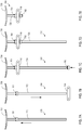
- FIGS. 1A-1B provide alternative views of an eyelid support assembly 100 (i.e., an assembly for lifting an eyelid, such as a lower eyelid). More particularly, FIG. 1A provides a front view of the eyelid support assembly 100. FIG. 1B provides a side view of the eyelid support assembly 100.
- the eyelid support assembly 100 includes a mounting plate 110, an elongate shaft 120, and an eyelid support member 130.
- the mounting plate 110 is configured for coupling to a facial bone, such as a zygomatic bone.
- the mounting plate 110 may be attached to a zygomatic bone via one or more fasteners 112 (e.g., bone screws).
- the mounting plate 110 may function as a scaffold to which one or more other elements of the eyelid support assembly 100 may be attached.
- the elongate shaft 120 is configured to extend between and couple the mounting plate 110 to the eyelid support member 130.
- the elongate shaft 120 is attached to both the mounting plate 110 and the eyelid support member 130, thereby coupling the mounting plate 110 to the eyelid support member 130.
- the elongate shaft 120 may be formed from flexible material that enables the elongate shaft 120 to follow a tortuous path, such as the path shown in FIG. 1B (see also FIG. 9 ).
- the elongate shaft 120, the mounting plate 110, and/or the eyelid support member 130 are integrally formed.
- one or more of these components are manufactured separately and subsequently attached to the remaining components via a fastener (e.g., an adhesive, welding, compressions bars, crimping beads, screws, etc.).
- a fastener e.g., an adhesive, welding, compressions bars, crimping beads, screws, etc.
- the elongate shaft and the eyelid support member are integrally formed and attached to the mounting plate via a fastener.
- the length of the elongate shaft 120 of the eyelid support assembly 100 may be selected to match the anatomical architecture of the patient. For example, in some patients, the distance from the zygomatic bone to the location where the bottom edge of the inferior tarsus should be located may be relatively long. In other patients, the distance from the zygomatic bone to the proper location of the inferior tarsus is relatively short. Accordingly, in some embodiments, a practitioner may select, from a variety of eyelid support assemblies of different lengths, an eyelid support assembly 100 that has an elongate shaft 120 of appropriate length to provide the proper amount of lift to an eyelid when the mounting plate 110 is secured to a facial bone of the patient.
- the eyelid support member 130 may be configured to contact eyelid tissue, thereby providing lift to a paralytic eyelid.
- the eyelid support member 130 contacts and/or couples to (e.g., via sutures that wrap around or go through) a lower portion of the inferior tarsus of the patient, thereby lifting the inferior tarsus (and the lower eyelid of the patient).
- the eyelid support member 130 may be configured to extend horizontally to approximate the width of the lower eyelid (i.e., the full length of the inferior tarsus).
- the eyelid support member 130 is curved (e.g., banana-shaped to follow the contour of the lower eyelid/inferior tarsus). In other embodiments, the eyelid support member may adopt a different shape.
- the components of the eyelid support assembly 100 may be made from any suitable material.
- one or more of the mounting plate 110, elongate shaft 120, and eyelid support member 130 comprise or consist essentially of a biocompatible polymer, such as ultra-high molecular weight polyethylene. More particularly, in some embodiments, the mounting plate comprises or consists essentially of ultra-high molecular weight polyethylene.
- one or more components, such as a mounting plate comprise or consist essentially of titanium.
- one or more of the mounting plate, the elongate shaft 120, and the eyelid support member 130 are formed from two or more different biocompatible polymers. For example, a component may be made by injecting different biocompatible polymers into a mold.
- the eyelid support assembly 100 may be used to support an eyelid, such as a paralytic lower eyelid.
- a paralytic eyelid may tend to droop, causing the eyelid to be disposed at a relatively low position.
- the eyelid support member 130 may act on eyelid tissue, such as the inferior tarsus, thereby lifting the eyelid to a desired position. Stated differently, the eyelid support member 130 may exert a force that causes the eyelid to be disposed higher than it would be in the absence of the eyelid support assembly 100.
- the lifting of the lower eyelid in this manner may (1) facilitate complete (or more complete) closure of the eyelids, (2) improve the cosmetic appearance of the eye region, and/or (3) reduce the risk and/or occurrence of ectropion, lid laxity, epiphora, lagophthalmos, and/or corneal damage.
- FIGS. 2A-2D depict an embodiment of an eyelid support assembly 200 that resembles the eyelid support assembly 100 described above in certain respects. Accordingly, like features are designated with like reference numerals, with the leading digits incremented to "2."
- the embodiment depicted in FIGS. 2A-2D includes an eyelid support member 230 that may, in some respects, resemble the eyelid support member 130 of FIGS. 1A and 1B .
- Relevant disclosure set forth above regarding similarly identified features thus may not be repeated hereafter.
- specific features of eyelid support assemblies and related components shown in FIGS. 1A and 1B may not be shown or identified by a reference numeral in the drawings or specifically discussed in the written description that follows.
- FIGS. 2A-2D depict an adjustable-length eyelid support assembly 200 (i.e., an eyelid support assembly 200 having a length that may be adjusted by a practitioner). More particularly, FIG. 2A provides a front view of the eyelid support assembly 200 with a mounting plate 210 that is attached to a facial bone 50 of the patient. FIG. 2B provides a front view of the same eyelid support assembly 200, showing the cutting off of a portion of the elongate shaft 220. FIG. 2C provides a cross-sectional view of the eyelid support assembly 200 through line 2C-2C of FIG. 2A . FIG. 2D provides a perspective view of a portion of the eyelid support assembly 200.
- FIG. 2A provides a front view of the eyelid support assembly 200 with a mounting plate 210 that is attached to a facial bone 50 of the patient.
- FIG. 2B provides a front view of the same eyelid support assembly 200, showing the cutting off of a portion of the elongate shaft 220.
- FIG. 2C provides
- eyelid support assembly 200 is shown with reference to the exterior of a patient's face (i.e., is shown outward relative to the patient's flesh), one of ordinary skill in the art, with the benefit of this disclosure, will recognize that the eyelid support assembly 200 is generally implanted below the skin of a patient.
- the eyelid support assembly 200 includes a mounting plate 210, an elongate shaft 220, and an eyelid support member 230.
- the elongate shaft 220 and the eyelid support member 230 constitute a single inseparable unit.
- the mounting plate 210 is configured for coupling to a facial bone 50.
- the mounting plate 210 is attached or otherwise coupled to a zygomatic bone of a patient via one or more fasteners 212.
- fasteners 212 such as bone screws, may extend through the mounting plate 210 and sink into facial bone 50, thereby securing the mounting plate 210 relative to the bone structure of the patient.
- the mounting plate 210 is contoured to match the surface of the patient's facial bone 50.
- the facial bone 50 is shaved to receive the profile of a mounting plate 210. In some embodiments, such as that depicted in FIG.
- the mounting plate 210 is attached to the facial bone 50 such that mounting plate 210 is disposed directly below the center of the orbit.
- the mounting plate is disposed at a position lateral to a center of the patient's eye socket, having an elongate shaft that extends medially from the mounting plate toward the sagittal plane of the patient such that the eyelid support member is disposed directly below the center of the orbit to support the lower eyelid of the patient.
- the mounting plate 210 (e.g., a mounting plate principally made from ultra-high molecular weight polyetheylene) includes a sheet 240 or layer that is configured for contacting facial bone. Stated differently, the sheet 240 may be disposed between a facial bone 50 and the remaining portions of the mounting plate 210. In some embodiments, the sheet 240 is attached (e.g., via an adhesive) to the remaining portion of the mounting plate. In other or further embodiments, the sheet 240 is held against the remaining portion of mounting plate 210 via one or more fasteners 212. In some embodiments, the sheet 240 is a mesh layer or a layer formed by sputter coating. In other or further embodiments, the sheet 240 comprises and/or consists essentially of titanium.
- an uneven (rough) titanium layer e.g., a titanium mesh sheet or applied coating of titanium
- Other embodiments e.g,. embodiments in which a titanium mounting plate includes a textured lower surface
- the mounting plate 210 comprises a channel 214.
- the channel 214 may run perpendicular to a longitudinal axis of the mounting plate 210.
- the channel 214 may also be sized and shaped to receive a bottom portion of the elongate shaft 220.
- the channel 214 may be configured to allow a bottom portion of the elongate shaft 220 to pass through the channel 214.
- the channel 214 and the elongate shaft 220 both include cross-sections that are substantially oval in shape.
- the oblong cross-sectional shapes of the channel 214 and the elongate shaft 220 prevent the elongate shaft 220 from rotating within the channel 214.
- channels and elongate shafts of different shapes and sizes are also suitable for use and within the scope of this disclosure.
- the practitioner may first secure the mounting plate 210 by attaching or otherwise coupling the mounting plate 210 to a facial bone 50 of the patient. For example, in some circumstances, the practitioner may attach the mounting plate 210 to a zygomatic bone of the patient. The practitioner may then thread the bottom portion of the elongate shaft 220 through the channel 214 of the mounting plate 210. As a first (i.e., bottom) end of the elongate shaft 220 is advanced (e.g., slid) through the channel 214, the distance between the mounting plate 210 and a second end of the elongate shaft 220 decreases.
- the practitioner can adjust the distance between the mounting plate 210 and the second end of the elongate shaft 220. Such adjustment may be accomplished while implanting the eyelid support assembly 200 in a patient. In this manner, a practitioner can adjust the position of an eyelid support member 230 that is coupled to the elongate shaft 220 relative to the mounting plate 210. Stated differently, the adjustable eyelid support assembly 200 may be adjusted to ensure that an eyelid support member 230 is properly positioned to support an eyelid in a manner that takes into account the specific structure of the patient's face.
- an elongate shaft 220 with a second end that is coupled to an eyelid support member 230 may be inserted through a channel 214 of the mounting plate 210 until the eyelid support member 230 is disposed adjacent (e.g., directly below) the inferior tarsus of the patient.
- the practitioner may then suture or otherwise couple the eyelid support member 230 to the inferior tarsus.
- the practitioner may then adjust the position of the eyelid support member 230 (e.g., to lift the eyelid) by moving the elongate shaft 220 relative to the mounting plate 210.
- the elongate shaft 220 may be secured relative to the mounting plate 210.
- an adhesive 5 e.g., cyanoacrylate glue
- a port 216 of the mounting plate 210 see FIG. 2D to secure the elongate shaft 220 relative to the mounting plate.
- an adhesive 5 to secure the elongate shaft 220 relative to the mounting plate 210 may be facilitated by one or more grooves of the elongate shaft 220.
- the elongate shaft 220 may comprise one or more grooves 222 that run perpendicular to the longitudinal axis of the elongate shaft 220.
- the adhesive 5 may flow around the grooves 220.
- the adhesive 5 may thus extend around the perimeter (e.g., circumference) of the elongate shaft 220 and permanently bond the elongate shaft 220 to the mounting plate 210.
- any portion of the elongate shaft 220 that has passed through the entire mounting plate 210 may be cut off and discarded (see FIG. 2B ).
- the elongate shaft 220 When the elongate shaft 220 is positioned within and bonded to (or otherwise fixedly coupled to) the mounting plate 210, the elongate shaft 220 may extend along a path that is substantially equidistant from the sagittal plane of the patient at all points along the path. Stated differently, the elongate shaft 220 may run substantially parallel to the sagittal plane of the patient.
- FIGS. 3A-3C depict an eyelid support assembly 300 or components thereof according to another embodiment. More particularly, FIG. 3A provides a cross-sectional view of the eyelid support assembly 300.
- FIG. 3B provides a bottom view of a first portion 311 of the mounting plate 310 shown in FIG. 3A .
- FIG. 3C provides a top view of a second portion 319 of the same mounting plate 310.
- the first portion 311 is disposed generally above the second portion 319 when the mounting plate 310 is viewed as shown in FIG. 3A .
- the second portion 319 of the mounting plate 310 may be disposed closer to the facial bone 50 than the first portion 311 of the mounting plate 310.
- the distance between the first portion 311 of the mounting plate 310 and the facial bone 50 may be greater than the distance between the second portion 319 of the mounting plate 310 and the facial bone 50.
- the eyelid support assembly 300 includes a mounting plate 310, an elongate shaft 320, and an eyelid support member 330 (not shown).
- the mounting plate 310 of the eyelid support assembly 300 includes two distinct components: a first portion 311 and a second portion 319.
- one or more of the first portion 311 and the second portion 319 comprise or consist essentially of titanium.
- the second portion 319 of the mounting plate 310 includes an aperture 360 that runs adjacent to and along a portion of the length of an elongate shaft 320 that is disposed within the second portion 319 of the mounting plate 310.
- the first portion 311 of the mounting plate 310 may include a compression bar 350 that extends from the remainder of the first portion 311 (see FIGS. 3A and 3B ).
- the compression bar 350 may comprise or consist essentially of titanium. Further, in some embodiments, the compression bar 350 includes a plurality of grooves. The compression bar 350 may be sized and shaped to extend through the aperture 360 of the second portion 319 of the mounting plate 310 to engage with the elongate shaft 320.
- the fasteners 312 may draw the first portion 311 of the mounting plate 310 toward the patient's facial bone 50.
- the compression bar 350 may extend through the aperture 360 to engage with and/or compress the elongate shaft 320. Engagement with and/or compression of the elongate shaft 320 by the compression bar 350 may restrict movement of the elongate shaft 320 within the channel 314.
- advancement of the fasteners 312 into the facial bone may promote frictional engagement of the compression bar 350 with the elongate shaft 320, thereby preventing movement of the elongate shaft 320 through the channel 314.
- While the depicted embodiment includes only a single compression bar 350, other embodiments may include a plurality of compression bars that are configured to extend through one or more apertures of a lower plate to engage with the elongate shaft.
- FIGS. 4A and 4B provide cross-sectional views of an elongate shaft 420 and a mounting plate 410 of another eyelid support assembly. More particularly, FIG. 4A depicts the insertion of an elongate shaft 420 into mounting plate 410. FIG. 4B depicts the same eyelid support assembly components after the elongate shaft 420 has been properly inserted and adhesive has been added to fixedly secure the elongate shaft 420 relative to the mounting plate 410.
- the elongate shaft 420 comprises a plurality of protrusions 424 that extend away from the longitudinal axis of the elongate shaft 420. These protrusions 424 form grooves that extend around the elongate shaft 420.
- the mounting plate 410 also includes a plurality of protrusions 418 that extend into the channel 414 of the mounting plate 410.
- the elongate shaft 420 may be inserted into the mounting plate 410.
- the protrusions 418 of the mounting plate 410 may deflect as the elongate shaft 420 is advanced within the mounting plate 410, thereby permitting the elongate shaft 420 to advance within the channel 414.
- the protrusions 424 of the elongate shaft 420 may contact and deflect the protrusions 418 of the mounting plate 410.
- the protrusions 418 of the mounting plate 410 may be configured to deflect in one direction to allow the elongate shaft 420 to enter, yet nonetheless prevent deflection in the opposite direction.
- the protrusions 418 may allow insertion of the elongate shaft 420 into the mounting plate 410, but not withdrawal of the elongate shaft 420 from the mounting plate 410.
- the protrusions 418 may be made from a material that differs from that of the rest of the mounting plate 410.
- the protrusions 418 may be made from or comprise a material that is more flexible than the material from which the rest of the mounting plate 410 is made.
- the protrusions 418 of the mounting plate 410 may interlock with the protrusions 424 of the elongate shaft 420, thereby preventing (or otherwise impeding) withdrawal of the elongate shaft 420 from the mounting plate 410.
- the elongate shaft 420 may be fixedly secured to the mounting plate 410 to prevent both further insertion and withdrawal of the elongate shaft 420.
- an adhesive 5 may be delivered through a port 416 of the mounting plate 410. The adhesive may flow around the elongate shaft 420 and fill any voids between the elongate shaft 420 and the mounting plate 410, thereby fixedly bonding the elongate shaft 420 to the mounting plate 410.
- protrusions 418 of FIGS. 4A and 4B are described as permitting only insertion (and not withdrawal) of the elongate shaft 420 from the mounting plate, in other embodiments, the protrusions do not prevent withdrawal of the elongate shaft 420 from the mounting plate 410. In other words, in some embodiments, the protrusions 418 allow the elongate shaft 420 to move in both directions.
- FIGS. 5A and 5B depict an eyelid support assembly 500 according to another embodiment. More particularly, FIG. 5A provides a front view of the eyelid support assembly 500, while FIG. 5B provides a cross-sectional view of the eyelid support assembly 500 through line 5B-5B of FIG. 5A .
- the eyelid support assembly 500 may comprise a mounting plate 510, an elongate shaft 520, and an eyelid support member 530.
- the mounting plate 510 is configured for coupling to facial bone 50 of the patient.
- the mounting plate 510 may be attached to a zygomatic bone, maxilla, or other facial bone of a patient via one or more fasteners 512, such as bone screws.
- the mounting plate 510 may also comprise a channel 514.
- the channel 514 may be sized and shaped to receive the elongate shaft 520 of the eyelid support assembly 500.
- the mounting plate 510 may also comprise a hole 517 for facilitating coupling of the elongate shaft 520 to the mounting plate 510.
- the hole 517 may be sized and shaped to receive a fastener 513, such as a self-tapping bone screw.
- the elongate shaft 520 includes a plurality of holes 526.
- the plurality of holes 526 may be aligned along a longitudinal axis of the elongate shaft 520.
- the elongate shaft 520 may be inserted into the channel 514 of the mounting plate 510 until the elongate shaft 520 is properly positioned for facilitating the support of a lower eyelid.
- the elongate shaft 520 may be inserted such that an eyelid support member 530 disposed at the second end of the elongate shaft 520 (i.e., the end of the elongate shaft 520 that is not inserted into the channel 514) is positioned to properly lift the lower eyelid of the patient.
- a hole 517 of the mounting plate 510 may be aligned with one of the plurality of holes 526 of the elongate shaft 520.
- a fastener 513 such as a bonescrew, may be inserted through both the hole 517 and one of the plurality of holes 526 of the elongate shaft 520, thereby fixing the distance between the mounting plate 510 and the eyelid support member 530.
- the inserted fastener 513 may fixedly attach the mounting plate 510 to the elongate shaft 520, thereby defining the distance from the mounting plate 510 to an eyelid support member 530 that is coupled to the second end of the elongate shaft 520.
- FIG. 6 provides a cross-sectional view of an eyelid support assembly 600 according to another embodiment.
- the eyelid support assembly 600 includes a mounting plate 610, an elongate shaft 620, and an eyelid support member (not shown).
- the mounting plate 610 comprises a channel 614 with a cross-section that is rectangular in shape.
- the embodiment depicted in FIG. 6 is analogous to the embodiment depicted in FIGS. 5A and 5B , except that the elongate shaft 620 does not include a plurality of holes.
- the elongate shaft 620 may be inserted into the channel 614 of the mounting plate until the elongate shaft 620 has been inserted to the proper extent.
- a fastener 613 such as a compression screw, may be used to press the elongate shaft 620 against the channel 614 to secure the elongate shaft 620 relative to the mounting plate 610.
- FIGS. 7A-7E depict various states of an eyelid support assembly 700, according to another embodiment.
- the eyelid support assembly 700 is configured for securing an elongate shaft 720 to a mounting plate 710 via crimping beads 701, 702.
- the crimping beads 701, 702 may be bands or rings of circular, oval, rectangular, or some other shape that may be compressed to clamp around the elongate shaft 720.
- a first crimping bead 701 may initially be slipped around a first (i.e., bottom) end of the elongate shaft 720. Then, as shown in FIG.
- the bottom end of the elongate shaft 720 may be inserted through a channel of a mounting plate 710 that has been mounted to a facial (e.g., zygomatic) bone of the patient until an eyelid support member 730 that is attached to a second (i.e., top) end of the elongate shaft is disposed adjacent (e.g., directly below) the inferior tarsus of the patient.
- the eyelid support member 730 may then be attached (e.g., sutured) to the inferior tarsus.
- the first crimping bead 701 may be compressed at a position that is just above the mounting plate 710. Then, as shown in FIGS. 7C and 7D , a second crimping bead 702 may be placed over the bottom end of the elongate shaft 720 and pushed upward until the second crimping bead 702 is disposed immediately below the mounting plate 710. The second crimping bead 702 may then be compressed, thereby securing the elongate shaft 720 to the mounting plate 710.
- the tail of the elongate shaft 720 may be cut off and discarded as shown in FIG. 7E .
- the crimping beads 701, 702 may be used in connection with one or more other fasteners.
- a set screw may also be used to lock the position of the elongate shaft 720 relative to the mounting plate 710.
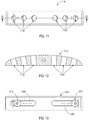
- FIGS. 8A and 8B provide alternative views of a mounting plate 810 for an eyelid support assembly, according to another embodiment. More particularly, FIG. 8A provides a side view of the mounting plate 810, while FIG. 8B provides a top view of the mounting plate 810.
- the mounting plate 810 is configured for coupling to facial bone, such as the zygomatic bone.
- the mounting plate 810 may be attached to a zygomatic bone via one or more fasteners that are inserted through apertures 803 in the mounting plate 810.
- the mounting plate 810 may function as a scaffold to which one or more other elements of an eyelid support assembly may be attached.
- the mounting plate 810 includes a central region 804 and a pair of lateral regions 806, where the central region 804 is thicker than the lateral regions 806. In some embodiments, the central region 804 gradually rises from the lateral regions 806 to form a relatively smooth hump.
- the central region 804 may include a channel 814 that is designed to accommodate an elongate shaft.
- a mounting plate 810 that is designed to have relatively thin lateral regions 806 and a thicker central region 804 may allow for sufficient structure to accommodate an elongate shaft while minimizing the amount of unnecessarily implanted material.
- the mounting plate 810 may be made from any suitable material (e.g., titanium).
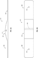
- FIG. 9 provides a partially cut-away side view of an eyelid support assembly 900 that is positioned to lift a lower eyelid of a patient.
- the eyelid support assembly 900 includes a mounting plate 910, an elongate shaft 920, and an eyelid support member 930.
- the mounting plate 910 is attached to facial bone 50 (e.g., the zygomatic bone) of the patient via one or more fasteners 912.
- the elongate shaft 920 extends in a generally upward direction from the mounting plate 910.
- the elongate shaft 920 may extend upward from the mounting plate 910 along the orbital septum 55 or nearby anatomy.
- the eyelid support member 930 may be attached or otherwise coupled to the second (i.e., top) end of the elongate shaft 920.
- the support member 930 and elongate shaft 920 may be integrally formed.
- the elongate shaft 920 may be adjusted by the practitioner to position the eyelid support member 930 such that the eyelid support member 930 lifts the inferior tarsus 70 of the patient.
- the eyelid support member 930 may be sutured or otherwise attached to the inferior tarsus 70. Accordingly, as the elongate shaft 920 is displaced in a manner that results in lifting the eyelid support member 930, the eyelid support member 930 may lift the inferior tarsus 70 of the patient, thereby providing support to a lower eyelid.
- Such support may both lift a lower eyelid and/or draw the eyelid toward the patient's eye.
- the force supplied by the eyelid support assembly 900 may push the patient's eyelid both upward and inward (i.e., toward the patient's eye).
- FIG. 10 provides a perspective view of a portion of an eyelid support assembly, according to another embodiment. More specifically, FIG. 10 depicts an elongate shaft 1020 that is attached to an eyelid support member 1030.
- the eyelid support member 1030 includes a mesh exterior 1032.
- the mesh exterior 1032 may substantially define the shape of the eyelid support member 1030.
- the mesh exterior of the eyelid support member 1030 is curved in shape.
- the mesh exterior 1032 may be formed from ultra-high molecular weight polyethylene or any other suitable material.
- the eyelid support member 1030 may also include a core interior region 1034.
- the core interior region 1034 may comprise and/or be filled with biocompatible acellular material derived from skin, such as Alloderm® or other similar materials. Stated differently, the core interior region 1034 may comprise and/or be filled with a collagen-rich matrix. Such material may serve as a scaffold on which living cells of the patient may grow. The use of such material may improve the biocompatibility of the eyelid support assembly. Additionally or alternatively, the use of such material may promote the growth of cells onto the implanted eyelid support member 1030. Such improved growth may promote improved bonding between the eyelid support member 1030 and tissue adjacent the lower eyelid.
- FIG. 11 provides a front view of a mounting plate 1110 of an eyelid support assembly according to another embodiment.
- FIG. 12 provides a cross-sectional view of the mounting plate 1110 through the line 12-12 of FIG. 11 .
- the mounting plate 1110 includes a plurality of apertures 1103 that may be used when fastening the mounting plate 1110 to bone of the patient.
- the mounting plate 1110 includes one, two, three, four, five, six, or more apertures 1103.
- Some mounting plates that include a plurality of apertures, such as the mounting plate 1110, may allow a practitioner to select where to place fastener(s) among multiple options.
- the mounting plate 1110 may be secured to the zygomatic bone of a patient via two screws, one of which is placed in any of the three apertures 1103 on a first side of the center of the mounting plate 1110.
- the second screw may be placed in any of the three apertures 1103 on the second (i.e., opposite) side of the center of the mounting plate 1110.
- the practitioner may select where to place each fastener based on the bone density of the patient. For example, the practitioner may choose to place a screw through a hole that is positioned adjacent to bone of sufficient density.
- screws placed adjacent the lateral edges of the mounting plate 1110 may extend further into the bone of the patient than screws that are placed adjacent the center of the mounting plate 1110.
- more than two fasteners may be used in connecting with mounting plates 1110 that have a plurality of apertures 1103.
- FIG. 13 provides a front view of a mounting plate 1210 according to another embodiment.
- the mounting plate 1210 includes at least one lateral channel 1209 that allows for adjustable placement of fastener(s) 1212.
- the mounting plate 1210 includes two lateral channels 1209.
- a first fastener 1212 e.g., a screw
- a second fastener 1212 e.g., a screw
- the practitioner may determine placement of the fasteners 1212 based on the bone density of the patient. Stated differently, the practitioner may place the fasteners 1212 at positions along the lateral channel 1209 where the bone of the patient is sufficiently dense.
- the upper surface of the mounting plate 1210 may taper laterally from the center of the mounting plate 1210.
- fasteners 1212 placed adjacent the lateral edges of the mounting plate 1210 may extend further into the bone of the patient than fasteners 1212 that are placed adjacent the center of the mounting plate 1210.
- more than two fasteners 1212 may be used in connection with mounting plates 1210 that have lateral channels 1209.
- a 3 ⁇ 1 ⁇ 25 mm elongate shaft was attached to a 4 ⁇ 4 ⁇ 3 mm mounting plate using a cyanoacrylate glue which was delivered through a 1 ⁇ 3 mm port of the mounting plate. After the cyanoacrylate glue had dried, the mounting plate was immobilized. The end of the elongate shaft disposed opposite the immobilized mounting plate was then deflected laterally from the resting position a distance of 4 mm in both directions at a rate of 30 cycles/minute.
- the mounting plate, the elongate shaft, and the connection between the mounting plate and the elongate shaft were examined at 8 (14,400 cycles), 16 (28,800 cycles), 24 (43,200 cycles), and 48 hours (86,400 cycles). Both the mounting plate and the elongate shaft survived the entire testing period without noticeable damage. The cyanoacrylate bond between the elongate shaft and the mounting plate likewise survived the entire testing period. There was no observable damage to the glued joint.
- Any methods disclosed herein include one or more steps or actions for performing the described method.
- the method steps and/or actions may be interchanged with one another.
- the order and/or use of specific steps and/or actions may be modified.
- sub-routines or only a portion of a method described herein may be a separate method within the scope of this disclosure. Stated otherwise, some methods may include only a portion of the steps described in a more detailed method.
Landscapes
- Health & Medical Sciences (AREA)
- Ophthalmology & Optometry (AREA)
- Engineering & Computer Science (AREA)
- Biomedical Technology (AREA)
- Heart & Thoracic Surgery (AREA)
- Vascular Medicine (AREA)
- Life Sciences & Earth Sciences (AREA)
- Animal Behavior & Ethology (AREA)
- General Health & Medical Sciences (AREA)
- Public Health (AREA)
- Veterinary Medicine (AREA)
- Plastic & Reconstructive Surgery (AREA)
- Nuclear Medicine, Radiotherapy & Molecular Imaging (AREA)
- Surgery (AREA)
- Cardiology (AREA)
- Oral & Maxillofacial Surgery (AREA)
- Transplantation (AREA)
- Prostheses (AREA)
Description
- This application claims priority to United States Provisional Application No.
62/181,383 - The present disclosure relates generally to the field of medical devices, such as medical devices for supporting a lower eyelid.
- Lower eyelid paralysis affects tens of thousands of people worldwide. Similar conditions may also affect other mammals, such as dogs. Paralysis of the lower eyelid may result in ectropion, lid laxity, epiphora, lagophthalmos, and/or corneal damage. Corrective measures for lower eyelid paralysis include surgical reconstruction and/or implantation of lower eyelid spacers to stabilize and support lower eyelids. Eyelid support devices are known from
US 2015/105858 andDE 431950 C ; general soft-tissue lifting devices are also known, for exampleUS 2008/200993 . However, existing devices and methods for treating lower eyelid paralysis suffer from one or more drawbacks or may perform less than optimally in one or more respects. Certain embodiments disclosed herein can address one or more of these issues. - The written disclosure herein describes illustrative embodiments that are non-limiting and non-exhaustive. Reference is made to certain of such illustrative embodiments that are depicted in the figures, in which:
-
FIG. 1A is a front view of an eyelid support assembly. -
FIG. 1B is a side view of the eyelid support assembly ofFIG. 1 . -
FIG. 2A is a front view of an eyelid support assembly that is configured for adjusting the distance between the mounting plate and the eyelid support member. -
FIG. 2B is a front view of the eyelid support assembly ofFIG. 2A , depicting the cutting off of a bottom portion of the elongate shaft. -
FIG. 2C is a cross-sectional view of the eyelid support assembly ofFIG. 2A throughline 2C-2C ofFIG. 2A . -
FIG. 2D is a perspective view of a portion of the eyelid support assembly ofFIG. 2A , depicting delivery of an adhesive to fasten the elongate shaft to the mounting plate. -
FIG. 3A is a cross-sectional view of an eyelid support assembly with a mounting plate that has a first portion and a second portion. -
FIG. 3B is a bottom view of the first portion of the mounting plate ofFIG. 3A . -
FIG. 3C is a top view of the second portion of the mounting plate ofFIG. 3A . -
FIG. 4A is a cross-sectional view of an eyelid support assembly wherein the elongate shaft is being inserted into the mounting plate. -
FIG. 4B is a cross-sectional view of the eyelid support assembly ofFIG. 4A , depicting the delivery of an adhesive to fasten the elongate shaft to the mounting plate. -
FIG. 5A is a front view of an eyelid support assembly according to another embodiment. -
FIG. 5B is a cross-sectional view of the eyelid support assembly ofFIG. 5A throughline 5B-5B. -
FIG. 6 is a cross-sectional view of an eyelid support assembly according to another embodiment. -
FIG. 7A is a front view of components of an eyelid support assembly in a first configuration. -
FIG. 7B is a front view of components of the eyelid support assembly ofFIG. 7A in a second configuration. -
FIG. 7C is a front view of components of the eyelid support assembly ofFIG. 7A-7B in a third configuration. -
FIG. 7D is a front view of components of the eyelid support assembly ofFIG. 7A-7C in a fourth configuration. -
FIG. 7E is a front view of components of the eyelid support assembly ofFIG. 7A-7D in a fifth configuration. -
FIG. 8A is a side view of mounting plate. -
FIG. 8B is a top view of the mounting plate ofFIG. 8A . -
FIG. 9 is partially cut-away side view of an eyelid support member positioned to support an inferior tarsus of a lower eyelid. -
FIG. 10 is a perspective view of an eyelid support member and an elongate shaft of an eyelid support assembly. -
FIG. 11 is a front view of a mounting plate of an eyelid support member according to another embodiment. -
FIG. 12 is a cross-sectional view of the mounting ofFIG. 11 through line 12-12. -
FIG. 13 is a font view of a mounting plate of any eyelid support member according to another embodiment. - The components of the embodiments as generally described and illustrated in the figures herein can be arranged and designed in a wide variety of different configurations. Thus, the following more detailed description of various embodiments, as represented in the figures, is not intended to limit the scope of the present disclosure, but is merely representative of various embodiments. While various aspects of the embodiments are presented in the drawings, the drawings are not necessarily drawn to scale unless specifically indicated.
- The phrases "connected to" and "coupled to" are used in their ordinary sense, and are broad enough to refer to any suitable coupling or other form of interaction between two or more entities, including mechanical, frictional, compression, fluid and thermal interaction. Two components may be coupled to each other even though they are not in direct contact with each other. For example, a first component may be coupled to a second component through a third component. The phrases "attached to" or "attached directly to" refer to interaction between two or more entities which are in direct contact with each other and/or are separated from each other only by a fastener of any suitable variety (e.g., screws, compression screws, compression bars, clamps, crimping beads, or an adhesive). The term patient is broad enough to include both human and other non-human mammalian patients.
- Many humans and other mammals suffer from lower eyelid paralysis or other conditions that afflict a lower eyelid. Such conditions may, among other things, cause the lower eyelid to turn outward, increase the laxity of the lower eyelid, and/or impede the complete closure of the eyelids. Lower eyelid problems can also promote irritation, discomfort, infection, and/or corneal damage. Such problems may also negatively affect the cosmetic appearance of the eye region.
- Eyelid support assemblies can be used to lift or otherwise support a lower eyelid. For example, in some embodiments disclosed herein, an eyelid support assembly includes a mounting plate, an elongate shaft, and an eyelid support member. The mounting plate may be attached or otherwise coupled to a facial bone (e.g., a zygomatic bone, maxilla, or other facial bone above the lower jaw) to function as a scaffold to which one or more other elements of the eyelid support assembly may be attached. For example, the elongate shaft may include a first end that is attached to a mounting plate and a second end that is attached to an eyelid support member. Stated differently, the elongate shaft may extend between and couple the mounting plate to the eyelid support member. In some embodiments, the eyelid support member is attached (e.g., sutured) to an inferior tarsus of a patient's lower eyelid. For example, the eyelid support member may be disposed beneath, attached to, and in contact with the inferior tarsus along the entire length of the inferior tarsus. Due to the attachment of the eyelid support assembly to both facial bone (through the mounting plate) and the inferior tarsus (through the eyelid support member), the eyelid support member may exert an upward and/or inward force that lifts or otherwise displaces the patient's eyelid. Such displacement may improve the position of the lower eyelid.
- In some embodiments, the eyelid support assembly is integrally formed, while in other embodiments the eyelid support assembly is assembled by coupling the component parts of the eyelid support assembly to one another.
- In some embodiments, a kit, such as a surgical kit, may be supplied for supporting a lower eyelid. The kit may include one or more of the following: a mounting plate, an eyelid support member, an elongate shaft, a fastener (e.g., a screw) for coupling a mounting plate to a facial bone, a fastener (e.g., a screw or crimping bead) for coupling the elongate shaft to the mounting plate, a sterilizing agent, an alignment jig, a screwdriver, a crimping tool, an adhesive, an adhesive dispenser, a box, etc. In some embodiments, the adhesive is a cyanoacrylate glue or a thermoplastic (e.g., HDPE). In some embodiments, the adhesive dispenser is a cyanoacrylate glue dispenser or a dispenser for delivering a thermoplastic (e.g., HDPE) at an elevated temperature.
- In some examples an eyelid support assembly may be implanted into a patient. Implanting an eyelid support assembly may involve coupling the eyelid support member to a facial bone of a patient such that the eyelid support member is positioned to lift up the inferior tarsus. For example, implanting an eyelid support assembly may involve one or more of the following steps: coupling a mounting plate to a facial bone; inserting an elongate shaft through a channel of the mounting plate; securing the elongate shaft relative to the mounting plate; attaching (e.g., suturing) an eyelid support member to an inferior tarsus (e.g., a lower portion of the inferior tarsus); etc.
-
FIGS. 1A-1B provide alternative views of an eyelid support assembly 100 (i.e., an assembly for lifting an eyelid, such as a lower eyelid). More particularly,FIG. 1A provides a front view of theeyelid support assembly 100.FIG. 1B provides a side view of theeyelid support assembly 100. Theeyelid support assembly 100 includes a mountingplate 110, anelongate shaft 120, and aneyelid support member 130. - In the embodiment depicted in
FIGS. 1A and1B , the mountingplate 110 is configured for coupling to a facial bone, such as a zygomatic bone. For example, the mountingplate 110 may be attached to a zygomatic bone via one or more fasteners 112 (e.g., bone screws). The mountingplate 110 may function as a scaffold to which one or more other elements of theeyelid support assembly 100 may be attached. - The
elongate shaft 120 is configured to extend between and couple the mountingplate 110 to theeyelid support member 130. For example, inFIGS. 1A and1B , theelongate shaft 120 is attached to both the mountingplate 110 and theeyelid support member 130, thereby coupling the mountingplate 110 to theeyelid support member 130. Theelongate shaft 120 may be formed from flexible material that enables theelongate shaft 120 to follow a tortuous path, such as the path shown inFIG. 1B (see alsoFIG. 9 ). In the embodiment depicted inFIGS. 1A and1B , theelongate shaft 120, the mountingplate 110, and/or theeyelid support member 130 are integrally formed. In other embodiments, one or more of these components are manufactured separately and subsequently attached to the remaining components via a fastener (e.g., an adhesive, welding, compressions bars, crimping beads, screws, etc.). For example, in some embodiments, the elongate shaft and the eyelid support member are integrally formed and attached to the mounting plate via a fastener. - The length of the
elongate shaft 120 of theeyelid support assembly 100 may be selected to match the anatomical architecture of the patient. For example, in some patients, the distance from the zygomatic bone to the location where the bottom edge of the inferior tarsus should be located may be relatively long. In other patients, the distance from the zygomatic bone to the proper location of the inferior tarsus is relatively short. Accordingly, in some embodiments, a practitioner may select, from a variety of eyelid support assemblies of different lengths, aneyelid support assembly 100 that has anelongate shaft 120 of appropriate length to provide the proper amount of lift to an eyelid when the mountingplate 110 is secured to a facial bone of the patient. - The
eyelid support member 130 may be configured to contact eyelid tissue, thereby providing lift to a paralytic eyelid. For example, in some embodiments, theeyelid support member 130 contacts and/or couples to (e.g., via sutures that wrap around or go through) a lower portion of the inferior tarsus of the patient, thereby lifting the inferior tarsus (and the lower eyelid of the patient). Theeyelid support member 130 may be configured to extend horizontally to approximate the width of the lower eyelid (i.e., the full length of the inferior tarsus). In some embodiments, theeyelid support member 130 is curved (e.g., banana-shaped to follow the contour of the lower eyelid/inferior tarsus). In other embodiments, the eyelid support member may adopt a different shape. - The components of the
eyelid support assembly 100 may be made from any suitable material. For example, in some embodiments, one or more of the mountingplate 110,elongate shaft 120, andeyelid support member 130 comprise or consist essentially of a biocompatible polymer, such as ultra-high molecular weight polyethylene. More particularly, in some embodiments, the mounting plate comprises or consists essentially of ultra-high molecular weight polyethylene. In some embodiments, one or more components, such as a mounting plate, comprise or consist essentially of titanium. In some embodiments, one or more of the mounting plate, theelongate shaft 120, and theeyelid support member 130 are formed from two or more different biocompatible polymers. For example, a component may be made by injecting different biocompatible polymers into a mold. - The
eyelid support assembly 100 may be used to support an eyelid, such as a paralytic lower eyelid. For example, in the absence of corrective measures, a paralytic eyelid may tend to droop, causing the eyelid to be disposed at a relatively low position. Theeyelid support member 130 may act on eyelid tissue, such as the inferior tarsus, thereby lifting the eyelid to a desired position. Stated differently, theeyelid support member 130 may exert a force that causes the eyelid to be disposed higher than it would be in the absence of theeyelid support assembly 100. The lifting of the lower eyelid in this manner may (1) facilitate complete (or more complete) closure of the eyelids, (2) improve the cosmetic appearance of the eye region, and/or (3) reduce the risk and/or occurrence of ectropion, lid laxity, epiphora, lagophthalmos, and/or corneal damage. -
FIGS. 2A-2D depict an embodiment of an eyelid support assembly 200 that resembles theeyelid support assembly 100 described above in certain respects. Accordingly, like features are designated with like reference numerals, with the leading digits incremented to "2." For example, the embodiment depicted inFIGS. 2A-2D includes aneyelid support member 230 that may, in some respects, resemble theeyelid support member 130 ofFIGS. 1A and1B . Relevant disclosure set forth above regarding similarly identified features thus may not be repeated hereafter. Moreover, specific features of eyelid support assemblies and related components shown inFIGS. 1A and1B may not be shown or identified by a reference numeral in the drawings or specifically discussed in the written description that follows. However, such features may clearly be the same, or substantially the same, as features depicted in other embodiments and/or described with respect to such embodiments. Accordingly, the relevant descriptions of such features apply equally to the features of the eyelid support assembly 200 and related components depicted inFIGS. 2A-2D . Any suitable combination of the features, and variations of the same, described with respect to theeyelid support assembly 100 and related components illustrated inFIGS. 1A and1B can be employed with the eyelid support assembly 200 and related components ofFIGS. 2A-2D , and vice versa. This pattern of disclosure applies equally to further embodiments depicted in subsequent figures and described hereafter, wherein the leading digits may be further incremented. -
FIGS. 2A-2D depict an adjustable-length eyelid support assembly 200 (i.e., an eyelid support assembly 200 having a length that may be adjusted by a practitioner). More particularly,FIG. 2A provides a front view of the eyelid support assembly 200 with a mountingplate 210 that is attached to afacial bone 50 of the patient.FIG. 2B provides a front view of the same eyelid support assembly 200, showing the cutting off of a portion of theelongate shaft 220.FIG. 2C provides a cross-sectional view of the eyelid support assembly 200 throughline 2C-2C ofFIG. 2A .FIG. 2D provides a perspective view of a portion of the eyelid support assembly 200. While the eyelid support assembly 200 is shown with reference to the exterior of a patient's face (i.e., is shown outward relative to the patient's flesh), one of ordinary skill in the art, with the benefit of this disclosure, will recognize that the eyelid support assembly 200 is generally implanted below the skin of a patient. - As depicted in these figures, the eyelid support assembly 200 includes a mounting
plate 210, anelongate shaft 220, and aneyelid support member 230. In the depicted embodiment, theelongate shaft 220 and theeyelid support member 230 constitute a single inseparable unit. - In the embodiment depicted in
FIGS. 2A-2D , the mountingplate 210 is configured for coupling to afacial bone 50. For instance, in some embodiments, the mountingplate 210 is attached or otherwise coupled to a zygomatic bone of a patient via one ormore fasteners 212. Stated differently,fasteners 212, such as bone screws, may extend through the mountingplate 210 and sink intofacial bone 50, thereby securing the mountingplate 210 relative to the bone structure of the patient. In some embodiments, the mountingplate 210 is contoured to match the surface of the patient'sfacial bone 50. In other or further embodiments, thefacial bone 50 is shaved to receive the profile of a mountingplate 210. In some embodiments, such as that depicted inFIG. 2A , the mountingplate 210 is attached to thefacial bone 50 such that mountingplate 210 is disposed directly below the center of the orbit. In other or further embodiments, the mounting plate is disposed at a position lateral to a center of the patient's eye socket, having an elongate shaft that extends medially from the mounting plate toward the sagittal plane of the patient such that the eyelid support member is disposed directly below the center of the orbit to support the lower eyelid of the patient. - In some embodiments, the mounting plate 210 (e.g., a mounting plate principally made from ultra-high molecular weight polyetheylene) includes a
sheet 240 or layer that is configured for contacting facial bone. Stated differently, thesheet 240 may be disposed between afacial bone 50 and the remaining portions of the mountingplate 210. In some embodiments, thesheet 240 is attached (e.g., via an adhesive) to the remaining portion of the mounting plate. In other or further embodiments, thesheet 240 is held against the remaining portion of mountingplate 210 via one ormore fasteners 212. In some embodiments, thesheet 240 is a mesh layer or a layer formed by sputter coating. In other or further embodiments, thesheet 240 comprises and/or consists essentially of titanium. For example, in some embodiments, an uneven (rough) titanium layer (e.g., a titanium mesh sheet or applied coating of titanium) may contactfacial bone 50 to facilitate bone growth and/or bonding to thesheet 240. Other embodiments (e.g,. embodiments in which a titanium mounting plate includes a textured lower surface) may lack a sheet analogous to thesheet 240. - In the depicted embodiment, the mounting
plate 210 comprises achannel 214. Thechannel 214 may run perpendicular to a longitudinal axis of the mountingplate 210. Thechannel 214 may also be sized and shaped to receive a bottom portion of theelongate shaft 220. Stated differently, thechannel 214 may be configured to allow a bottom portion of theelongate shaft 220 to pass through thechannel 214. In the depicted embodiment, thechannel 214 and theelongate shaft 220 both include cross-sections that are substantially oval in shape. The oblong cross-sectional shapes of thechannel 214 and theelongate shaft 220 prevent theelongate shaft 220 from rotating within thechannel 214. One of ordinary skill in the art, with the benefit of this disclosure, will recognize that channels and elongate shafts of different shapes and sizes (e.g., channels and shafts with circular or rectangular cross sections) are also suitable for use and within the scope of this disclosure. - When implanting the eyelid support assembly 200, the practitioner may first secure the mounting
plate 210 by attaching or otherwise coupling the mountingplate 210 to afacial bone 50 of the patient. For example, in some circumstances, the practitioner may attach the mountingplate 210 to a zygomatic bone of the patient. The practitioner may then thread the bottom portion of theelongate shaft 220 through thechannel 214 of the mountingplate 210. As a first (i.e., bottom) end of theelongate shaft 220 is advanced (e.g., slid) through thechannel 214, the distance between the mountingplate 210 and a second end of theelongate shaft 220 decreases. Thus, by varying the degree to which theelongate shaft 220 is advanced through thechannel 214, the practitioner can adjust the distance between the mountingplate 210 and the second end of theelongate shaft 220. Such adjustment may be accomplished while implanting the eyelid support assembly 200 in a patient. In this manner, a practitioner can adjust the position of aneyelid support member 230 that is coupled to theelongate shaft 220 relative to the mountingplate 210. Stated differently, the adjustable eyelid support assembly 200 may be adjusted to ensure that aneyelid support member 230 is properly positioned to support an eyelid in a manner that takes into account the specific structure of the patient's face. - For instance, an
elongate shaft 220 with a second end that is coupled to aneyelid support member 230 may be inserted through achannel 214 of the mountingplate 210 until theeyelid support member 230 is disposed adjacent (e.g., directly below) the inferior tarsus of the patient. In some circumstances, the practitioner may then suture or otherwise couple theeyelid support member 230 to the inferior tarsus. The practitioner may then adjust the position of the eyelid support member 230 (e.g., to lift the eyelid) by moving theelongate shaft 220 relative to the mountingplate 210. Once theelongate shaft 220 has been positioned within the mountingplate 210 such that the second end of theelongate shaft 220 is placed a proper distance from the mountingplate 210, theelongate shaft 220 may be secured relative to the mountingplate 210. For example, an adhesive 5 (e.g., cyanoacrylate glue) may be delivered through aport 216 of the mounting plate 210 (seeFIG. 2D ) to secure theelongate shaft 220 relative to the mounting plate. - Delivery of an adhesive 5 to secure the
elongate shaft 220 relative to the mountingplate 210 may be facilitated by one or more grooves of theelongate shaft 220. For example, in some embodiments, theelongate shaft 220 may comprise one ormore grooves 222 that run perpendicular to the longitudinal axis of theelongate shaft 220. Upon delivery of an adhesive 5 through theport 216, the adhesive 5 may flow around thegrooves 220. By flowing around thegrooves 220, the adhesive 5 may thus extend around the perimeter (e.g., circumference) of theelongate shaft 220 and permanently bond theelongate shaft 220 to the mountingplate 210. - Once the
elongate shaft 220 has been properly positioned relative to the mountingplate 210 and secured to the mountingplate 210, any portion of theelongate shaft 220 that has passed through the entire mounting plate 210 (e.g., the first end of the elongate shaft 220) may be cut off and discarded (seeFIG. 2B ). - When the
elongate shaft 220 is positioned within and bonded to (or otherwise fixedly coupled to) the mountingplate 210, theelongate shaft 220 may extend along a path that is substantially equidistant from the sagittal plane of the patient at all points along the path. Stated differently, theelongate shaft 220 may run substantially parallel to the sagittal plane of the patient. -
FIGS. 3A-3C depict aneyelid support assembly 300 or components thereof according to another embodiment. More particularly,FIG. 3A provides a cross-sectional view of theeyelid support assembly 300.FIG. 3B provides a bottom view of afirst portion 311 of the mountingplate 310 shown inFIG. 3A . AndFIG. 3C provides a top view of asecond portion 319 of the same mountingplate 310. In the depicted embodiment, thefirst portion 311 is disposed generally above thesecond portion 319 when the mountingplate 310 is viewed as shown inFIG. 3A . Stated differently, when the mountingplate 310 is coupled to thefacial bone 50, thesecond portion 319 of the mountingplate 310 may be disposed closer to thefacial bone 50 than thefirst portion 311 of the mountingplate 310. In other words, when the mountingplate 310 is coupled to thefacial bone 50, the distance between thefirst portion 311 of the mountingplate 310 and thefacial bone 50 may be greater than the distance between thesecond portion 319 of the mountingplate 310 and thefacial bone 50. - The
eyelid support assembly 300 includes a mountingplate 310, anelongate shaft 320, and an eyelid support member 330 (not shown). As noted above, the mountingplate 310 of theeyelid support assembly 300 includes two distinct components: afirst portion 311 and asecond portion 319. In some embodiments, one or more of thefirst portion 311 and thesecond portion 319 comprise or consist essentially of titanium. - In the depicted embodiment, the
second portion 319 of the mountingplate 310 includes anaperture 360 that runs adjacent to and along a portion of the length of anelongate shaft 320 that is disposed within thesecond portion 319 of the mountingplate 310. - The
first portion 311 of the mountingplate 310 may include acompression bar 350 that extends from the remainder of the first portion 311 (seeFIGS. 3A and3B ). Thecompression bar 350 may comprise or consist essentially of titanium. Further, in some embodiments, thecompression bar 350 includes a plurality of grooves. Thecompression bar 350 may be sized and shaped to extend through theaperture 360 of thesecond portion 319 of the mountingplate 310 to engage with theelongate shaft 320. - For instance, as the
fasteners 312 are advanced into thefacial bone 50, the fasteners may draw thefirst portion 311 of the mountingplate 310 toward the patient'sfacial bone 50. By drawing thefirst portion 311 of the mountingplate 310 toward the patient'sfacial bone 50, thecompression bar 350 may extend through theaperture 360 to engage with and/or compress theelongate shaft 320. Engagement with and/or compression of theelongate shaft 320 by thecompression bar 350 may restrict movement of theelongate shaft 320 within thechannel 314. Stated differently, advancement of thefasteners 312 into the facial bone may promote frictional engagement of thecompression bar 350 with theelongate shaft 320, thereby preventing movement of theelongate shaft 320 through thechannel 314. - While the depicted embodiment includes only a
single compression bar 350, other embodiments may include a plurality of compression bars that are configured to extend through one or more apertures of a lower plate to engage with the elongate shaft. -
FIGS. 4A and4B provide cross-sectional views of anelongate shaft 420 and a mountingplate 410 of another eyelid support assembly. More particularly,FIG. 4A depicts the insertion of anelongate shaft 420 into mountingplate 410.FIG. 4B depicts the same eyelid support assembly components after theelongate shaft 420 has been properly inserted and adhesive has been added to fixedly secure theelongate shaft 420 relative to the mountingplate 410. - In
FIGS. 4A and4B , theelongate shaft 420 comprises a plurality ofprotrusions 424 that extend away from the longitudinal axis of theelongate shaft 420. Theseprotrusions 424 form grooves that extend around theelongate shaft 420. The mountingplate 410 also includes a plurality ofprotrusions 418 that extend into thechannel 414 of the mountingplate 410. - As depicted in
FIG. 4A , theelongate shaft 420 may be inserted into the mountingplate 410. Theprotrusions 418 of the mountingplate 410 may deflect as theelongate shaft 420 is advanced within the mountingplate 410, thereby permitting theelongate shaft 420 to advance within thechannel 414. Stated differently, as theelongate shaft 420 is inserted into the mountingplate 410, theprotrusions 424 of theelongate shaft 420 may contact and deflect theprotrusions 418 of the mountingplate 410. Theprotrusions 418 of the mountingplate 410 may be configured to deflect in one direction to allow theelongate shaft 420 to enter, yet nonetheless prevent deflection in the opposite direction. In other words, theprotrusions 418 may allow insertion of theelongate shaft 420 into the mountingplate 410, but not withdrawal of theelongate shaft 420 from the mountingplate 410. Theprotrusions 418 may be made from a material that differs from that of the rest of the mountingplate 410. For example, theprotrusions 418 may be made from or comprise a material that is more flexible than the material from which the rest of the mountingplate 410 is made. - Once the
elongate shaft 420 has been inserted such that the second end of the elongate shaft 420 (i.e., the end of theelongate shaft 420 that is not inserted into the mounting plate 410) is disposed a proper distance from the mountingplate 410, theprotrusions 418 of the mountingplate 410 may interlock with theprotrusions 424 of theelongate shaft 420, thereby preventing (or otherwise impeding) withdrawal of theelongate shaft 420 from the mountingplate 410. - The
elongate shaft 420 may be fixedly secured to the mountingplate 410 to prevent both further insertion and withdrawal of theelongate shaft 420. For example, as depicted inFIG. 4B , an adhesive 5 may be delivered through aport 416 of the mountingplate 410. The adhesive may flow around theelongate shaft 420 and fill any voids between theelongate shaft 420 and the mountingplate 410, thereby fixedly bonding theelongate shaft 420 to the mountingplate 410. - While the
protrusions 418 ofFIGS. 4A and4B are described as permitting only insertion (and not withdrawal) of theelongate shaft 420 from the mounting plate, in other embodiments, the protrusions do not prevent withdrawal of theelongate shaft 420 from the mountingplate 410. In other words, in some embodiments, theprotrusions 418 allow theelongate shaft 420 to move in both directions. -
FIGS. 5A and5B depict aneyelid support assembly 500 according to another embodiment. More particularly,FIG. 5A provides a front view of theeyelid support assembly 500, whileFIG. 5B provides a cross-sectional view of theeyelid support assembly 500 throughline 5B-5B ofFIG. 5A . With reference toFIGS. 5A and5B , theeyelid support assembly 500 may comprise a mountingplate 510, anelongate shaft 520, and aneyelid support member 530. - In the depicted embodiment, the mounting
plate 510 is configured for coupling tofacial bone 50 of the patient. For example, the mountingplate 510 may be attached to a zygomatic bone, maxilla, or other facial bone of a patient via one ormore fasteners 512, such as bone screws. The mountingplate 510 may also comprise achannel 514. Thechannel 514 may be sized and shaped to receive theelongate shaft 520 of theeyelid support assembly 500. The mountingplate 510 may also comprise ahole 517 for facilitating coupling of theelongate shaft 520 to the mountingplate 510. Thehole 517 may be sized and shaped to receive afastener 513, such as a self-tapping bone screw. - As shown in the depicted embodiment, the
elongate shaft 520 includes a plurality ofholes 526. The plurality ofholes 526 may be aligned along a longitudinal axis of theelongate shaft 520. Theelongate shaft 520 may be inserted into thechannel 514 of the mountingplate 510 until theelongate shaft 520 is properly positioned for facilitating the support of a lower eyelid. For example, theelongate shaft 520 may be inserted such that aneyelid support member 530 disposed at the second end of the elongate shaft 520 (i.e., the end of theelongate shaft 520 that is not inserted into the channel 514) is positioned to properly lift the lower eyelid of the patient. - Once the
elongate shaft 520 has been properly positioned relative to the mounting plate, ahole 517 of the mountingplate 510 may be aligned with one of the plurality ofholes 526 of theelongate shaft 520. When these holes are properly aligned, afastener 513, such as a bonescrew, may be inserted through both thehole 517 and one of the plurality ofholes 526 of theelongate shaft 520, thereby fixing the distance between the mountingplate 510 and theeyelid support member 530. Stated differently, the insertedfastener 513 may fixedly attach the mountingplate 510 to theelongate shaft 520, thereby defining the distance from the mountingplate 510 to aneyelid support member 530 that is coupled to the second end of theelongate shaft 520. -
FIG. 6 provides a cross-sectional view of aneyelid support assembly 600 according to another embodiment. Theeyelid support assembly 600 includes a mountingplate 610, anelongate shaft 620, and an eyelid support member (not shown). In the depicted embodiment, the mountingplate 610 comprises achannel 614 with a cross-section that is rectangular in shape. - The embodiment depicted in
FIG. 6 is analogous to the embodiment depicted inFIGS. 5A and5B , except that theelongate shaft 620 does not include a plurality of holes. Theelongate shaft 620 may be inserted into thechannel 614 of the mounting plate until theelongate shaft 620 has been inserted to the proper extent. Then afastener 613, such as a compression screw, may be used to press theelongate shaft 620 against thechannel 614 to secure theelongate shaft 620 relative to the mountingplate 610. -
FIGS. 7A-7E depict various states of aneyelid support assembly 700, according to another embodiment. As shown inFIGS. 7A-7E , theeyelid support assembly 700 is configured for securing anelongate shaft 720 to a mountingplate 710 via crimpingbeads beads elongate shaft 720. For example, as shown inFIG. 7A , a first crimpingbead 701 may initially be slipped around a first (i.e., bottom) end of theelongate shaft 720. Then, as shown inFIG. 7B , the bottom end of theelongate shaft 720 may be inserted through a channel of a mountingplate 710 that has been mounted to a facial (e.g., zygomatic) bone of the patient until aneyelid support member 730 that is attached to a second (i.e., top) end of the elongate shaft is disposed adjacent (e.g., directly below) the inferior tarsus of the patient. In some circumstances, theeyelid support member 730 may then be attached (e.g., sutured) to the inferior tarsus. Once theelongate shaft 720 is positioned within the mountingplate 710 such that theeyelid support member 730 is placed a proper distance from the mountingplate 710, the first crimpingbead 701 may be compressed at a position that is just above the mountingplate 710. Then, as shown inFIGS. 7C and 7D , a second crimpingbead 702 may be placed over the bottom end of theelongate shaft 720 and pushed upward until the second crimpingbead 702 is disposed immediately below the mountingplate 710. The second crimpingbead 702 may then be compressed, thereby securing theelongate shaft 720 to the mountingplate 710. Once theelongate shaft 720 is secured to the mountingplate 710, the tail of theelongate shaft 720 may be cut off and discarded as shown inFIG. 7E . In some embodiments, the crimpingbeads elongate shaft 720 relative to the mountingplate 710. -
FIGS. 8A and 8B provide alternative views of a mountingplate 810 for an eyelid support assembly, according to another embodiment. More particularly,FIG. 8A provides a side view of the mountingplate 810, whileFIG. 8B provides a top view of the mountingplate 810. The mountingplate 810 is configured for coupling to facial bone, such as the zygomatic bone. For example, the mountingplate 810 may be attached to a zygomatic bone via one or more fasteners that are inserted throughapertures 803 in the mountingplate 810. The mountingplate 810 may function as a scaffold to which one or more other elements of an eyelid support assembly may be attached. - In the embodiment depicted in
FIGS. 8A and 8B , the mountingplate 810 includes acentral region 804 and a pair oflateral regions 806, where thecentral region 804 is thicker than thelateral regions 806. In some embodiments, thecentral region 804 gradually rises from thelateral regions 806 to form a relatively smooth hump. Thecentral region 804 may include achannel 814 that is designed to accommodate an elongate shaft. A mountingplate 810 that is designed to have relatively thinlateral regions 806 and a thickercentral region 804 may allow for sufficient structure to accommodate an elongate shaft while minimizing the amount of unnecessarily implanted material. The mountingplate 810 may be made from any suitable material (e.g., titanium). -
FIG. 9 provides a partially cut-away side view of aneyelid support assembly 900 that is positioned to lift a lower eyelid of a patient. Theeyelid support assembly 900 includes a mountingplate 910, anelongate shaft 920, and aneyelid support member 930. - As depicted in
FIG. 9 , the mountingplate 910 is attached to facial bone 50 (e.g., the zygomatic bone) of the patient via one ormore fasteners 912. Theelongate shaft 920 extends in a generally upward direction from the mountingplate 910. For instance, in some embodiments, theelongate shaft 920 may extend upward from the mountingplate 910 along the orbital septum 55 or nearby anatomy. - The
eyelid support member 930 may be attached or otherwise coupled to the second (i.e., top) end of theelongate shaft 920. For example, thesupport member 930 andelongate shaft 920 may be integrally formed. Theelongate shaft 920 may be adjusted by the practitioner to position theeyelid support member 930 such that theeyelid support member 930 lifts theinferior tarsus 70 of the patient. For example, theeyelid support member 930 may be sutured or otherwise attached to theinferior tarsus 70. Accordingly, as theelongate shaft 920 is displaced in a manner that results in lifting theeyelid support member 930, theeyelid support member 930 may lift theinferior tarsus 70 of the patient, thereby providing support to a lower eyelid. Such support may both lift a lower eyelid and/or draw the eyelid toward the patient's eye. In other words, the force supplied by theeyelid support assembly 900 may push the patient's eyelid both upward and inward (i.e., toward the patient's eye). -
FIG. 10 provides a perspective view of a portion of an eyelid support assembly, according to another embodiment. More specifically,FIG. 10 depicts anelongate shaft 1020 that is attached to aneyelid support member 1030. - In the depicted embodiment, the
eyelid support member 1030 includes amesh exterior 1032. Themesh exterior 1032 may substantially define the shape of theeyelid support member 1030. For example, in the depicted embodiment, the mesh exterior of theeyelid support member 1030 is curved in shape. Themesh exterior 1032 may be formed from ultra-high molecular weight polyethylene or any other suitable material. - The
eyelid support member 1030 may also include a coreinterior region 1034. The coreinterior region 1034 may comprise and/or be filled with biocompatible acellular material derived from skin, such as Alloderm® or other similar materials. Stated differently, the coreinterior region 1034 may comprise and/or be filled with a collagen-rich matrix. Such material may serve as a scaffold on which living cells of the patient may grow. The use of such material may improve the biocompatibility of the eyelid support assembly. Additionally or alternatively, the use of such material may promote the growth of cells onto the implantedeyelid support member 1030. Such improved growth may promote improved bonding between theeyelid support member 1030 and tissue adjacent the lower eyelid. -
FIG. 11 provides a front view of a mountingplate 1110 of an eyelid support assembly according to another embodiment.FIG. 12 provides a cross-sectional view of the mountingplate 1110 through the line 12-12 ofFIG. 11 . The mountingplate 1110 includes a plurality ofapertures 1103 that may be used when fastening the mountingplate 1110 to bone of the patient. In some embodiments, the mountingplate 1110 includes one, two, three, four, five, six, ormore apertures 1103. Some mounting plates that include a plurality of apertures, such as the mountingplate 1110, may allow a practitioner to select where to place fastener(s) among multiple options. For example, the mountingplate 1110 may be secured to the zygomatic bone of a patient via two screws, one of which is placed in any of the threeapertures 1103 on a first side of the center of the mountingplate 1110. The second screw may be placed in any of the threeapertures 1103 on the second (i.e., opposite) side of the center of the mountingplate 1110. The practitioner may select where to place each fastener based on the bone density of the patient. For example, the practitioner may choose to place a screw through a hole that is positioned adjacent to bone of sufficient density. As the upper surface of the mountingplate 1110 tapers laterally from the center of the mountingplate 1110, screws placed adjacent the lateral edges of the mountingplate 1110 may extend further into the bone of the patient than screws that are placed adjacent the center of the mountingplate 1110. In some circumstances, more than two fasteners may be used in connecting with mountingplates 1110 that have a plurality ofapertures 1103. -
FIG. 13 provides a front view of a mountingplate 1210 according to another embodiment. The mountingplate 1210 includes at least onelateral channel 1209 that allows for adjustable placement of fastener(s) 1212. For example, the mountingplate 1210 includes twolateral channels 1209. A first fastener 1212 (e.g., a screw) may be placed at any position along the length of one of thelateral channels 1209. A second fastener 1212 (e.g., a screw) may be placed at any position along the length of the otherlateral channel 1209. The practitioner may determine placement of thefasteners 1212 based on the bone density of the patient. Stated differently, the practitioner may place thefasteners 1212 at positions along thelateral channel 1209 where the bone of the patient is sufficiently dense. In some embodiments, the upper surface of the mountingplate 1210 may taper laterally from the center of the mountingplate 1210. Thus,fasteners 1212 placed adjacent the lateral edges of the mountingplate 1210 may extend further into the bone of the patient thanfasteners 1212 that are placed adjacent the center of the mountingplate 1210. In some embodiments and/or circumstances, more than twofasteners 1212 may be used in connection with mountingplates 1210 that havelateral channels 1209. - The following example is illustrative of disclosed methods and compositions. In light of this disclosure, those of skill in the art will recognize that variations of this example and other examples of the disclosed methods and compositions would be possible without undue experimentation.
- To test the stability of eyelid support assembly components, along with the connections between these components, a 3 × 1 × 25 mm elongate shaft was attached to a 4 × 4 × 3 mm mounting plate using a cyanoacrylate glue which was delivered through a 1 × 3 mm port of the mounting plate. After the cyanoacrylate glue had dried, the mounting plate was immobilized. The end of the elongate shaft disposed opposite the immobilized mounting plate was then deflected laterally from the resting position a distance of 4 mm in both directions at a rate of 30 cycles/minute. The mounting plate, the elongate shaft, and the connection between the mounting plate and the elongate shaft were examined at 8 (14,400 cycles), 16 (28,800 cycles), 24 (43,200 cycles), and 48 hours (86,400 cycles). Both the mounting plate and the elongate shaft survived the entire testing period without noticeable damage. The cyanoacrylate bond between the elongate shaft and the mounting plate likewise survived the entire testing period. There was no observable damage to the glued joint.
- Any methods disclosed herein include one or more steps or actions for performing the described method. The method steps and/or actions may be interchanged with one another. In other words, unless a specific order of steps or actions is required for proper operation of the embodiment, the order and/or use of specific steps and/or actions may be modified. Moreover, sub-routines or only a portion of a method described herein may be a separate method within the scope of this disclosure. Stated otherwise, some methods may include only a portion of the steps described in a more detailed method.
- Reference throughout this specification to "an embodiment" or "the embodiment" means that a particular feature, structure, or characteristic described in connection with that embodiment is included in at least one embodiment. Thus, the quoted phrases, or variations thereof, as recited throughout this specification are not necessarily all referring to the same embodiment.
- Similarly, it should be appreciated by one of skill in the art with the benefit of this disclosure that in the above description of embodiments, various features are sometimes grouped together in a single embodiment, figure, or description thereof for the purpose of streamlining the disclosure. This method of disclosure, however, is not to be interpreted as reflecting an intention that any claim requires more features than those expressly recited in that claim. Rather, as the following claims reflect, inventive aspects lie in a combination of fewer than all features of any single foregoing disclosed embodiment. Thus, the claims following this Detailed Description are hereby expressly incorporated into this Detailed Description, with each claim standing on its own as a separate embodiment. This disclosure includes all permutations of the independent claims with their dependent claims.
- Recitation in the claims of the term "first" with respect to a feature or element does not necessarily imply the existence of a second or additional such feature or element. It will be apparent to those having skill in the art that changes may be made to the details of the above-described embodiments without departing from the underlying principles of the present disclosure.
Claims (15)
- An assembly for lifting a lower eyelid, characterised by the assembly comprising:a mounting plate configured for coupling to a facial bone;an eyelid support member; andan elongate shaft configured to extend between and couple the mounting plate to the eyelid support member.
- The assembly of claim 1, wherein the elongate shaft is formed from flexible material.
- The assembly of any of claims 1 to 2, wherein the assembly is configured for implantation.
- The assembly of any of claims 1 to 3, wherein the eyelid support member is configured to contact and lift up an inferior tarsus.
- The assembly of any of claims 1 to 4, wherein the elongate shaft is attached to the mounting plate.
- The assembly of any of claims 1 to 5, wherein the mounting plate, the eyelid support member, and the elongate shaft are integrally formed.
- The assembly of any of claims 1 to 6, wherein the assembly is configured to allow adjustment of a distance between the mounting plate and the eyelid support member as the assembly is implanted into a patient.
- The assembly of any of claims 1 to 7, wherein prior to securement of the elongate shaft relative to the mounting plate, the elongate shaft is configured to slide within a channel of the mounting plate.
- The assembly of any of claims 1 to 8, wherein:the eyelid support member and the mounting plate are both coupled to the elongate shaft; andthe elongate shaft, when the assembly is implanted into the patient, extends along a path that is substantially equidistant from the sagittal plane of the patient at all points along the path.
- The assembly of any of claims 1 to 9, wherein the mounting plate comprises a port for receiving an adhesive.
- The assembly of any of claims 1 to 10, wherein the elongate shaft is coupled to the mounting plate via one or more of a compression screw and crimping beads.
- The assembly of claim 4, wherein the eyelid support member is attached to the inferior tarsus.
- The assembly of claim 12, wherein the eyelid support member is attached to the inferior tarsus via one or more sutures.
- The assembly of claim 1 to 13, wherein the eyelid support member comprises a core interior region.
- The assembly of claim 14, wherein the core interior region comprises biocompatible acellular material.
Applications Claiming Priority (2)
| Application Number | Priority Date | Filing Date | Title |
|---|---|---|---|
| US201562181383P | 2015-06-18 | 2015-06-18 | |
| PCT/US2016/037852 WO2016205499A1 (en) | 2015-06-18 | 2016-06-16 | Eyelid supporters and related methods |
Publications (3)
| Publication Number | Publication Date |
|---|---|
| EP3310308A1 EP3310308A1 (en) | 2018-04-25 |
| EP3310308A4 EP3310308A4 (en) | 2019-04-10 |
| EP3310308B1 true EP3310308B1 (en) | 2020-09-02 |
Family
ID=57546144
Family Applications (1)
| Application Number | Title | Priority Date | Filing Date |
|---|---|---|---|
| EP16812428.7A Active EP3310308B1 (en) | 2015-06-18 | 2016-06-16 | Eyelid supporters |
Country Status (5)
| Country | Link |
|---|---|
| US (1) | US11266493B2 (en) |
| EP (1) | EP3310308B1 (en) |
| JP (1) | JP6930968B2 (en) |
| CA (1) | CA3026068A1 (en) |
| WO (1) | WO2016205499A1 (en) |
Families Citing this family (2)
| Publication number | Priority date | Publication date | Assignee | Title |
|---|---|---|---|---|
| CN112587299B (en) * | 2020-12-17 | 2022-11-18 | 广西中医药大学第一附属医院 | Combined device for cataract operation |
| CN113425424B (en) * | 2021-08-05 | 2022-06-03 | 樊涛 | A design measuring tool for double-edged eyelid operation |
Family Cites Families (19)
| Publication number | Priority date | Publication date | Assignee | Title |
|---|---|---|---|---|
| DE431950C (en) * | 1925-11-06 | 1926-07-27 | Inst Kuenstliche Augen | Device for lifting paralyzed eyelids |
| US3710788A (en) | 1971-07-23 | 1973-01-16 | W Reeves | Eyelid support for invalids |
| US5522889A (en) * | 1995-01-13 | 1996-06-04 | University Of Kentucky Research Foundation | Apparatus and method for restoring eyelid function |
| US5843147A (en) | 1996-04-30 | 1998-12-01 | Medtronic, Inc. | Implantable eyelid electrode and method of implanting same |
| ATE420599T1 (en) | 2000-05-19 | 2009-01-15 | Coapt Systems Inc | FABRIC ADJUSTMENT DEVICE |
| WO2002022001A2 (en) | 2000-09-15 | 2002-03-21 | Macropore, Inc. | Cranial flap fixation device |
| AR033840A1 (en) * | 2000-10-04 | 2004-01-07 | Synthes Ag | AN ORTHOPEDIC DEVICE TO MODIFY THE DISTANCE BETWEEN THE MAXILAR AND THE CIGOMA OF A PATIENT |
| JP2005040250A (en) | 2003-07-25 | 2005-02-17 | Mizuho Co Ltd | Orthopaedic implant |
| US7686836B2 (en) * | 2004-05-13 | 2010-03-30 | Kls-Martin, L.P. | Bone distractor and method |
| US20070037120A1 (en) | 2005-07-29 | 2007-02-15 | Kurt Ritter | Facial support device |
| WO2007025290A2 (en) * | 2005-08-26 | 2007-03-01 | Isto Technologies, Inc. | Implants and methods for repair, replacement and treatment of joint disease |
| US7819899B2 (en) | 2006-01-03 | 2010-10-26 | Zimmer Spine, Inc. | Instrument for pedicle screw adhesive materials |
| US20080200993A1 (en) | 2007-02-15 | 2008-08-21 | Jenifer Lee Henderson | Temporal Brow Lifting and Fixation Device |
| US8449581B2 (en) | 2007-05-07 | 2013-05-28 | Stryker Trauma Gmbh | Sliding plate with reinforced slot |
| US20080288081A1 (en) * | 2007-05-16 | 2008-11-20 | Joel Scrafton | Implant articular surface wear reduction system |
| US8403968B2 (en) | 2007-12-26 | 2013-03-26 | Illuminoss Medical, Inc. | Apparatus and methods for repairing craniomaxillofacial bones using customized bone plates |
| WO2009091802A2 (en) | 2008-01-14 | 2009-07-23 | Zimmer, Inc. | A knee system and method of making same |
| US8097041B2 (en) | 2008-01-31 | 2012-01-17 | Epitera Solutions, Inc. | Infra-orbital implant |
| US10052186B2 (en) | 2013-10-10 | 2018-08-21 | Osteosymbionics Llc | Prosthetic implants |
-
2016
- 2016-06-16 EP EP16812428.7A patent/EP3310308B1/en active Active
- 2016-06-16 WO PCT/US2016/037852 patent/WO2016205499A1/en unknown
- 2016-06-16 JP JP2018517673A patent/JP6930968B2/en active Active
- 2016-06-16 US US15/737,056 patent/US11266493B2/en active Active
- 2016-06-16 CA CA3026068A patent/CA3026068A1/en active Pending
Non-Patent Citations (1)
| Title |
|---|
| None * |
Also Published As
| Publication number | Publication date |
|---|---|
| CA3026068A1 (en) | 2016-12-22 |
| US20180168799A1 (en) | 2018-06-21 |
| JP6930968B2 (en) | 2021-09-01 |
| US11266493B2 (en) | 2022-03-08 |
| EP3310308A4 (en) | 2019-04-10 |
| WO2016205499A1 (en) | 2016-12-22 |
| EP3310308A1 (en) | 2018-04-25 |
| JP2018518346A (en) | 2018-07-12 |
Similar Documents
| Publication | Publication Date | Title |
|---|---|---|
| US10327774B2 (en) | Force modulating tissue bridge | |
| US9649212B2 (en) | Release device for releasing a medical implant from a catheter and catheter comprising a release device | |
| AU2013329411B2 (en) | Surgical staple insertion device | |
| US10350332B2 (en) | Fixation of orthopaedic devices | |
| US10792141B2 (en) | Soft tissue implant and method of using same | |
| US20160000536A1 (en) | Removable system and method for dentures and surgical guides | |
| US9956072B2 (en) | Surgical template and delivery device | |
| JP2014516286A (en) | Fasteners, installation systems, and methods for ocular tissue closure and ocular artificial tissue fixation and other uses | |
| KR20160098105A (en) | Membrane for implant operation | |
| US9211190B2 (en) | Flex anchor for attaching a prosthesis to bone | |
| EP3310308B1 (en) | Eyelid supporters | |
| CN217851757U (en) | Sock cover and external member | |
| US20170281150A1 (en) | Bone and joint stabilization device features | |
| AU2016214148A1 (en) | Skin expansion system | |
| US20200253654A1 (en) | Bone and joint stabilization device features and delivery systems | |
| KR20150133671A (en) | Membrane for implant operation | |
| CN115553898B (en) | Module combined type internal fixation device suitable for anterior atlas internal fixation | |
| CN211796797U (en) | Centrum fixing device for dentata | |
| WO2016178869A1 (en) | Tendon fixation device | |
| DE202016004945U1 (en) | Universal magnetic implant for bone conduction hearing aids | |
| CA3149638A1 (en) | Dynamic bone plate and method of use | |
| CN112914788A (en) | Device and method for lifting skin tissue | |
| KR20070017315A (en) | Resorbable surgical fixation device |
Legal Events
| Date | Code | Title | Description |
|---|---|---|---|
| STAA | Information on the status of an ep patent application or granted ep patent |
Free format text: STATUS: THE INTERNATIONAL PUBLICATION HAS BEEN MADE |
|
| PUAI | Public reference made under article 153(3) epc to a published international application that has entered the european phase |
Free format text: ORIGINAL CODE: 0009012 |
|
| STAA | Information on the status of an ep patent application or granted ep patent |
Free format text: STATUS: REQUEST FOR EXAMINATION WAS MADE |
|
| 17P | Request for examination filed |
Effective date: 20180110 |
|
| AK | Designated contracting states |
Kind code of ref document: A1 Designated state(s): AL AT BE BG CH CY CZ DE DK EE ES FI FR GB GR HR HU IE IS IT LI LT LU LV MC MK MT NL NO PL PT RO RS SE SI SK SM TR |
|
| AX | Request for extension of the european patent |
Extension state: BA ME |
|
| DAV | Request for validation of the european patent (deleted) | ||
| DAX | Request for extension of the european patent (deleted) | ||
| A4 | Supplementary search report drawn up and despatched |
Effective date: 20190314 |
|
| RIC1 | Information provided on ipc code assigned before grant |
Ipc: A61F 9/007 20060101ALI20190307BHEP Ipc: A45D 44/22 20060101ALI20190307BHEP Ipc: A61F 9/00 20060101AFI20190307BHEP |
|
| GRAP | Despatch of communication of intention to grant a patent |
Free format text: ORIGINAL CODE: EPIDOSNIGR1 |
|
| STAA | Information on the status of an ep patent application or granted ep patent |
Free format text: STATUS: GRANT OF PATENT IS INTENDED |
|
| INTG | Intention to grant announced |
Effective date: 20200316 |
|
| GRAS | Grant fee paid |
Free format text: ORIGINAL CODE: EPIDOSNIGR3 |
|
| GRAA | (expected) grant |
Free format text: ORIGINAL CODE: 0009210 |
|
| STAA | Information on the status of an ep patent application or granted ep patent |
Free format text: STATUS: THE PATENT HAS BEEN GRANTED |
|
| AK | Designated contracting states |
Kind code of ref document: B1 Designated state(s): AL AT BE BG CH CY CZ DE DK EE ES FI FR GB GR HR HU IE IS IT LI LT LU LV MC MK MT NL NO PL PT RO RS SE SI SK SM TR |
|
| REG | Reference to a national code |
Ref country code: GB Ref legal event code: FG4D |
|
| REG | Reference to a national code |
Ref country code: AT Ref legal event code: REF Ref document number: 1307945 Country of ref document: AT Kind code of ref document: T Effective date: 20200915 Ref country code: CH Ref legal event code: EP |
|
| REG | Reference to a national code |
Ref country code: DE Ref legal event code: R096 Ref document number: 602016043367 Country of ref document: DE |
|
| REG | Reference to a national code |
Ref country code: IE Ref legal event code: FG4D |
|
| REG | Reference to a national code |
Ref country code: LT Ref legal event code: MG4D |
|
| PG25 | Lapsed in a contracting state [announced via postgrant information from national office to epo] |
Ref country code: SE Free format text: LAPSE BECAUSE OF FAILURE TO SUBMIT A TRANSLATION OF THE DESCRIPTION OR TO PAY THE FEE WITHIN THE PRESCRIBED TIME-LIMIT Effective date: 20200902 Ref country code: BG Free format text: LAPSE BECAUSE OF FAILURE TO SUBMIT A TRANSLATION OF THE DESCRIPTION OR TO PAY THE FEE WITHIN THE PRESCRIBED TIME-LIMIT Effective date: 20201202 Ref country code: LT Free format text: LAPSE BECAUSE OF FAILURE TO SUBMIT A TRANSLATION OF THE DESCRIPTION OR TO PAY THE FEE WITHIN THE PRESCRIBED TIME-LIMIT Effective date: 20200902 Ref country code: GR Free format text: LAPSE BECAUSE OF FAILURE TO SUBMIT A TRANSLATION OF THE DESCRIPTION OR TO PAY THE FEE WITHIN THE PRESCRIBED TIME-LIMIT Effective date: 20201203 Ref country code: NO Free format text: LAPSE BECAUSE OF FAILURE TO SUBMIT A TRANSLATION OF THE DESCRIPTION OR TO PAY THE FEE WITHIN THE PRESCRIBED TIME-LIMIT Effective date: 20201202 Ref country code: HR Free format text: LAPSE BECAUSE OF FAILURE TO SUBMIT A TRANSLATION OF THE DESCRIPTION OR TO PAY THE FEE WITHIN THE PRESCRIBED TIME-LIMIT Effective date: 20200902 Ref country code: FI Free format text: LAPSE BECAUSE OF FAILURE TO SUBMIT A TRANSLATION OF THE DESCRIPTION OR TO PAY THE FEE WITHIN THE PRESCRIBED TIME-LIMIT Effective date: 20200902 |
|
| REG | Reference to a national code |
Ref country code: NL Ref legal event code: MP Effective date: 20200902 |
|
| REG | Reference to a national code |
Ref country code: AT Ref legal event code: MK05 Ref document number: 1307945 Country of ref document: AT Kind code of ref document: T Effective date: 20200902 |
|
| PG25 | Lapsed in a contracting state [announced via postgrant information from national office to epo] |
Ref country code: LV Free format text: LAPSE BECAUSE OF FAILURE TO SUBMIT A TRANSLATION OF THE DESCRIPTION OR TO PAY THE FEE WITHIN THE PRESCRIBED TIME-LIMIT Effective date: 20200902 Ref country code: PL Free format text: LAPSE BECAUSE OF FAILURE TO SUBMIT A TRANSLATION OF THE DESCRIPTION OR TO PAY THE FEE WITHIN THE PRESCRIBED TIME-LIMIT Effective date: 20200902 Ref country code: RS Free format text: LAPSE BECAUSE OF FAILURE TO SUBMIT A TRANSLATION OF THE DESCRIPTION OR TO PAY THE FEE WITHIN THE PRESCRIBED TIME-LIMIT Effective date: 20200902 |
|
| PG25 | Lapsed in a contracting state [announced via postgrant information from national office to epo] |
Ref country code: EE Free format text: LAPSE BECAUSE OF FAILURE TO SUBMIT A TRANSLATION OF THE DESCRIPTION OR TO PAY THE FEE WITHIN THE PRESCRIBED TIME-LIMIT Effective date: 20200902 Ref country code: SM Free format text: LAPSE BECAUSE OF FAILURE TO SUBMIT A TRANSLATION OF THE DESCRIPTION OR TO PAY THE FEE WITHIN THE PRESCRIBED TIME-LIMIT Effective date: 20200902 Ref country code: CZ Free format text: LAPSE BECAUSE OF FAILURE TO SUBMIT A TRANSLATION OF THE DESCRIPTION OR TO PAY THE FEE WITHIN THE PRESCRIBED TIME-LIMIT Effective date: 20200902 Ref country code: RO Free format text: LAPSE BECAUSE OF FAILURE TO SUBMIT A TRANSLATION OF THE DESCRIPTION OR TO PAY THE FEE WITHIN THE PRESCRIBED TIME-LIMIT Effective date: 20200902 Ref country code: PT Free format text: LAPSE BECAUSE OF FAILURE TO SUBMIT A TRANSLATION OF THE DESCRIPTION OR TO PAY THE FEE WITHIN THE PRESCRIBED TIME-LIMIT Effective date: 20210104 |
|
| PG25 | Lapsed in a contracting state [announced via postgrant information from national office to epo] |
Ref country code: AT Free format text: LAPSE BECAUSE OF FAILURE TO SUBMIT A TRANSLATION OF THE DESCRIPTION OR TO PAY THE FEE WITHIN THE PRESCRIBED TIME-LIMIT Effective date: 20200902 Ref country code: AL Free format text: LAPSE BECAUSE OF FAILURE TO SUBMIT A TRANSLATION OF THE DESCRIPTION OR TO PAY THE FEE WITHIN THE PRESCRIBED TIME-LIMIT Effective date: 20200902 Ref country code: ES Free format text: LAPSE BECAUSE OF FAILURE TO SUBMIT A TRANSLATION OF THE DESCRIPTION OR TO PAY THE FEE WITHIN THE PRESCRIBED TIME-LIMIT Effective date: 20200902 Ref country code: IS Free format text: LAPSE BECAUSE OF FAILURE TO SUBMIT A TRANSLATION OF THE DESCRIPTION OR TO PAY THE FEE WITHIN THE PRESCRIBED TIME-LIMIT Effective date: 20210102 |
|
| REG | Reference to a national code |
Ref country code: DE Ref legal event code: R097 Ref document number: 602016043367 Country of ref document: DE |
|
| PG25 | Lapsed in a contracting state [announced via postgrant information from national office to epo] |
Ref country code: SK Free format text: LAPSE BECAUSE OF FAILURE TO SUBMIT A TRANSLATION OF THE DESCRIPTION OR TO PAY THE FEE WITHIN THE PRESCRIBED TIME-LIMIT Effective date: 20200902 |
|
| PLBE | No opposition filed within time limit |
Free format text: ORIGINAL CODE: 0009261 |
|
| STAA | Information on the status of an ep patent application or granted ep patent |
Free format text: STATUS: NO OPPOSITION FILED WITHIN TIME LIMIT |
|
| 26N | No opposition filed |
Effective date: 20210603 |
|
| PG25 | Lapsed in a contracting state [announced via postgrant information from national office to epo] |
Ref country code: DK Free format text: LAPSE BECAUSE OF FAILURE TO SUBMIT A TRANSLATION OF THE DESCRIPTION OR TO PAY THE FEE WITHIN THE PRESCRIBED TIME-LIMIT Effective date: 20200902 Ref country code: SI Free format text: LAPSE BECAUSE OF FAILURE TO SUBMIT A TRANSLATION OF THE DESCRIPTION OR TO PAY THE FEE WITHIN THE PRESCRIBED TIME-LIMIT Effective date: 20200902 |
|
| PG25 | Lapsed in a contracting state [announced via postgrant information from national office to epo] |
Ref country code: IT Free format text: LAPSE BECAUSE OF FAILURE TO SUBMIT A TRANSLATION OF THE DESCRIPTION OR TO PAY THE FEE WITHIN THE PRESCRIBED TIME-LIMIT Effective date: 20200902 |
|
| PG25 | Lapsed in a contracting state [announced via postgrant information from national office to epo] |
Ref country code: MC Free format text: LAPSE BECAUSE OF FAILURE TO SUBMIT A TRANSLATION OF THE DESCRIPTION OR TO PAY THE FEE WITHIN THE PRESCRIBED TIME-LIMIT Effective date: 20200902 |
|
| REG | Reference to a national code |
Ref country code: CH Ref legal event code: PL |
|
| REG | Reference to a national code |
Ref country code: BE Ref legal event code: MM Effective date: 20210630 |
|
| PG25 | Lapsed in a contracting state [announced via postgrant information from national office to epo] |
Ref country code: LU Free format text: LAPSE BECAUSE OF NON-PAYMENT OF DUE FEES Effective date: 20210616 |
|
| PG25 | Lapsed in a contracting state [announced via postgrant information from national office to epo] |
Ref country code: LI Free format text: LAPSE BECAUSE OF NON-PAYMENT OF DUE FEES Effective date: 20210630 Ref country code: IE Free format text: LAPSE BECAUSE OF NON-PAYMENT OF DUE FEES Effective date: 20210616 Ref country code: CH Free format text: LAPSE BECAUSE OF NON-PAYMENT OF DUE FEES Effective date: 20210630 |
|
| PG25 | Lapsed in a contracting state [announced via postgrant information from national office to epo] |
Ref country code: BE Free format text: LAPSE BECAUSE OF NON-PAYMENT OF DUE FEES Effective date: 20210630 |
|
| PG25 | Lapsed in a contracting state [announced via postgrant information from national office to epo] |
Ref country code: NL Free format text: LAPSE BECAUSE OF NON-PAYMENT OF DUE FEES Effective date: 20200923 Ref country code: CY Free format text: LAPSE BECAUSE OF FAILURE TO SUBMIT A TRANSLATION OF THE DESCRIPTION OR TO PAY THE FEE WITHIN THE PRESCRIBED TIME-LIMIT Effective date: 20200902 |
|
| P01 | Opt-out of the competence of the unified patent court (upc) registered |
Effective date: 20230527 |
|
| PG25 | Lapsed in a contracting state [announced via postgrant information from national office to epo] |
Ref country code: HU Free format text: LAPSE BECAUSE OF FAILURE TO SUBMIT A TRANSLATION OF THE DESCRIPTION OR TO PAY THE FEE WITHIN THE PRESCRIBED TIME-LIMIT; INVALID AB INITIO Effective date: 20160616 |
|
| PGFP | Annual fee paid to national office [announced via postgrant information from national office to epo] |
Ref country code: FR Payment date: 20230622 Year of fee payment: 8 Ref country code: DE Payment date: 20230626 Year of fee payment: 8 |
|
| PGFP | Annual fee paid to national office [announced via postgrant information from national office to epo] |
Ref country code: GB Payment date: 20230630 Year of fee payment: 8 |
|
| PG25 | Lapsed in a contracting state [announced via postgrant information from national office to epo] |
Ref country code: MK Free format text: LAPSE BECAUSE OF FAILURE TO SUBMIT A TRANSLATION OF THE DESCRIPTION OR TO PAY THE FEE WITHIN THE PRESCRIBED TIME-LIMIT Effective date: 20200902 |