EP3281820B1 - Station building power supply device - Google Patents
Station building power supply device Download PDFInfo
- Publication number
- EP3281820B1 EP3281820B1 EP17193969.7A EP17193969A EP3281820B1 EP 3281820 B1 EP3281820 B1 EP 3281820B1 EP 17193969 A EP17193969 A EP 17193969A EP 3281820 B1 EP3281820 B1 EP 3281820B1
- Authority
- EP
- European Patent Office
- Prior art keywords
- power
- capacitor unit
- soc
- unit
- station
- Prior art date
- Legal status (The legal status is an assumption and is not a legal conclusion. Google has not performed a legal analysis and makes no representation as to the accuracy of the status listed.)
- Active
Links
- 239000003990 capacitor Substances 0.000 claims description 111
- 238000006243 chemical reaction Methods 0.000 claims description 46
- 230000001172 regenerating effect Effects 0.000 claims description 39
- 238000001514 detection method Methods 0.000 claims description 9
- 238000007599 discharging Methods 0.000 description 18
- 230000009466 transformation Effects 0.000 description 17
- 238000000034 method Methods 0.000 description 9
- 230000007423 decrease Effects 0.000 description 7
- 238000010586 diagram Methods 0.000 description 6
- 230000007704 transition Effects 0.000 description 4
- 230000002457 bidirectional effect Effects 0.000 description 3
- 238000004378 air conditioning Methods 0.000 description 2
- 238000007796 conventional method Methods 0.000 description 2
- 239000013589 supplement Substances 0.000 description 2
- 230000009469 supplementation Effects 0.000 description 2
- 230000003247 decreasing effect Effects 0.000 description 1
- 230000000694 effects Effects 0.000 description 1
- 230000000087 stabilizing effect Effects 0.000 description 1
Images


Classifications
-
- H—ELECTRICITY
- H02—GENERATION; CONVERSION OR DISTRIBUTION OF ELECTRIC POWER
- H02J—CIRCUIT ARRANGEMENTS OR SYSTEMS FOR SUPPLYING OR DISTRIBUTING ELECTRIC POWER; SYSTEMS FOR STORING ELECTRIC ENERGY
- H02J3/00—Circuit arrangements for ac mains or ac distribution networks
-
- B—PERFORMING OPERATIONS; TRANSPORTING
- B60—VEHICLES IN GENERAL
- B60M—POWER SUPPLY LINES, AND DEVICES ALONG RAILS, FOR ELECTRICALLY- PROPELLED VEHICLES
- B60M3/00—Feeding power to supply lines in contact with collector on vehicles; Arrangements for consuming regenerative power
- B60M3/06—Arrangements for consuming regenerative power
-
- H—ELECTRICITY
- H02—GENERATION; CONVERSION OR DISTRIBUTION OF ELECTRIC POWER
- H02M—APPARATUS FOR CONVERSION BETWEEN AC AND AC, BETWEEN AC AND DC, OR BETWEEN DC AND DC, AND FOR USE WITH MAINS OR SIMILAR POWER SUPPLY SYSTEMS; CONVERSION OF DC OR AC INPUT POWER INTO SURGE OUTPUT POWER; CONTROL OR REGULATION THEREOF
- H02M3/00—Conversion of dc power input into dc power output
- H02M3/02—Conversion of dc power input into dc power output without intermediate conversion into ac
- H02M3/04—Conversion of dc power input into dc power output without intermediate conversion into ac by static converters
-
- H—ELECTRICITY
- H02—GENERATION; CONVERSION OR DISTRIBUTION OF ELECTRIC POWER
- H02M—APPARATUS FOR CONVERSION BETWEEN AC AND AC, BETWEEN AC AND DC, OR BETWEEN DC AND DC, AND FOR USE WITH MAINS OR SIMILAR POWER SUPPLY SYSTEMS; CONVERSION OF DC OR AC INPUT POWER INTO SURGE OUTPUT POWER; CONTROL OR REGULATION THEREOF
- H02M7/00—Conversion of ac power input into dc power output; Conversion of dc power input into ac power output
- H02M7/42—Conversion of dc power input into ac power output without possibility of reversal
- H02M7/44—Conversion of dc power input into ac power output without possibility of reversal by static converters
Description
- The present invention relates to a station-building power supply device that supplies power to electrical facilities (hereinafter, "station load") such as an air-conditioning system, a lighting system, and an elevator in a station yard using both AC power supplied from an AC system and the surplus regenerative power of trains.
- In recent years, regenerative power generated by regenerative brakes of trains is used as running power for other trains via a feeder in a DC feeding network. In such a DC feeding network, a feeding voltage increases when the regenerative power exceeds the running power in the same transformation zone, and the feeding voltage decreases when the regenerative power falls below the running power. For example, a conventional technique has been disclosed in which the surplus regenerative power occurring when regenerative power exceeds running power is transformed into AC power to be supplied to a station load via an AC system, the power that exceeds the consumption power for the station load is stored in a secondary battery, and the secondary battery is discharged when a feeding voltage is decreased to supply DC power to a feeder, thereby stabilizing the feeding voltage and also effectively using the surplus regenerative power to an extent that prevents a reverse power from flowing to the AC system (for example, Patent Literature 1).
Patent Literature 2 shows a control system of a power storage device for direct current electric railway.
Patent Literature 3 shows a control device and a control method.
Patent Literature 4 shows a railway feeding system. -
- Patent Literature 1: Japanese Patent No.
4432675 - Patent Literature 2:
JP 2013-095265 A - Patent Literature 3:
EP 2 426 570 A1 - Patent Literature 4:
JP 2013-023074 A - However, in the conventional technique listed above, power is regenerated to send to the AC system connected to the station load when surplus regenerative power occurs. Therefore, there is a problem in that a power amount of the AC system fluctuates intermittently and is destabilized.
- The present invention has been achieved in view of the above problem, and an objective of the present invention is to provide a station-building power supply device that can effectively use surplus regenerative power while suppressing fluctuations in the power amount of an AC system that supplies AC power to a station load.
- In order to solve the problem and achieve the objective, there is provided a station-building power supply device according to
claim 1. According to an example of the disclosure, there is provided a station-building power supply device that supplies power to a station load using both AC power supplied from an AC system and surplus regenerative power generated by trains. The station-building power supply device includes a feeding-voltage detection unit that detects a feeding voltage; a capacitor unit that stores therein the surplus regenerative power; an SOC (State Of Charge) detection unit that detects an SOC of the capacitor unit; a first power conversion unit that performs DC/DC power conversion in both directions between a feeder and the capacitor unit; a second power conversion unit that converts DC power supplied from the capacitor unit to AC power and supplies the AC power to the station load; and a control unit that controls the first power conversion unit and the second power conversion unit on the basis of the feeding voltage and the SOC. The control unit controls the first power conversion unit such that power is supplied from the feeder to the capacitor unit when the feeding voltage exceeds a predetermined first voltage threshold, and controls the second power conversion unit such that power is supplied from the capacitor unit to the station load when the SOC exceeds a predetermined first SOC threshold. - According to the present invention, surplus regenerative power can be effectively used while suppressing fluctuations in the power amount of an AC system that supplies AC power to a station load.
-
-
FIG. 1 is a diagram illustrating an example configuration of a station-building power supply device according to an embodiment. -
FIGS. 2 are diagrams illustrating an example of time charts of the station-building power supply device according to the embodiment. -
FIGS. 3 are diagrams illustrating an example of time charts of a conventional station-building power supply device not including a capacitor unit that stores therein surplus regenerative power. - Exemplary embodiments of a station-building power supply device according to the present invention will be explained below in detail with reference to the accompanying drawings. The present invention is not limited to the embodiments.
-
FIG. 1 is a diagram illustrating an example configuration of a station-building power supply device according to an embodiment of the present invention. In astation building 2, a transformer 3 that transforms high-voltage AC power supplied from an AC system 1 (an AC6600 V system in this example) into low-voltage AC power (an AC210 V system in this example) is provided in a station electrical room (not illustrated) or the like, and power is supplied to electrical facilities 4-1, 4-2, ··· and 4-n (hereinafter, "station loads 4") such as an air-conditioning system, a lighting system, and an elevator in the station yard. A station-buildingpower supply device 100 according to the present embodiment is configured to transform surplus regenerative power that has not been consumed in an electrical transformation zone in which trains 5 run into low-voltage AC power and to supply the AC power to thestation loads 4. That is, thestation loads 4 are supplied with both the AC power supplied from theAC system 1 and the surplus regenerative power in the electrical transformation zone. - As illustrated in
FIG. 1 , the station-buildingpower supply device 100 according to the present embodiment includes a feeding-voltage detection unit 8 that detects a feeding voltage (a DC1500 V system, in this example) between afeeder 6 and arail 7; acapacitor unit 9 that stores therein the surplus regenerative power generated in the electrical transformation zone in which the trains 5 run; anSOC detection unit 10 that detects an SOC (State Of Charge) of thecapacitor unit 9; a firstpower conversion unit 11 including a bidirectional DC/DC converter 21 that performs DC/DC power conversion in both directions between thefeeder 6 and thecapacitor unit 9; a secondpower conversion unit 12 including aninverter 22 that converts DC power supplied from thecapacitor unit 9 to AC power and atransformer 23 that converts an output from theinverter 22 into AC power (the AC210 V system in this example) to be supplied to thestation loads 4; and acontrol unit 13 that controls the firstpower conversion unit 11 and the secondpower conversion unit 12 on the basis of the feeding voltage and the SOC of thecapacitor unit 9. A known method can be used by theSOC detection unit 10 as a method of detecting the SOC, and the present invention is not limited by the method of detecting the SOC. In addition, the present invention is not limited by the circuit configuration of the bidirectional DC/DC converter 21 that constitutes the firstpower conversion unit 11 nor by the circuit configuration of theinverter 22 that constitutes the secondpower conversion unit 12. - The operational concept of the station-building
power supply device 100 according to the present embodiment is described next with reference toFIG. 1 . In the present embodiment, a voltage threshold (a first voltage threshold) for the feeding voltage and an SOC (State Of Charge) threshold (a first SOC threshold) for the SOC of thecapacitor unit 9 are set. - A value that indicates the occurrence of surplus regenerative power in the electrical transformation zone is set as the first voltage threshold and, when the feeding voltage exceeds the first voltage threshold, the
control unit 13 controls the firstpower conversion unit 11 such that power is supplied from thefeeder 6 to thecapacitor unit 9, thereby charging thecapacitor unit 9. - A value for indicating whether the
capacitor unit 9 can discharge is set as the first SOC threshold, and when the SOC of thecapacitor unit 9 exceeds the first SOC threshold, thecontrol unit 13 controls the secondpower conversion unit 12 such that it supplies power from thecapacitor unit 9 to thestation loads 4. - By performing such control as mentioned above, each time generation of surplus regenerative power in the electrical transformation zone occurs, the
capacitor unit 9 is charged with the surplus regenerative power, and power supplied continuously from theAC system 1 to thestation loads 4 can be supplemented with the surplus regenerative power charged in thecapacitor unit 9, while thecapacitor unit 9 maintains an SOC that enables discharging. Thus, the surplus regenerative power can be effectively used while fluctuations in the voltage of thefeeder 6 and fluctuations in the amount of power supplied from theAC system 1 are reduced. - The second
power conversion unit 12 is also controlled so as to cause the amount of power supplied from thecapacitor unit 9 to thestation loads 4 to be substantially constant and accordingly the amount of power supplied from theAC system 1 can be more stable. - Furthermore, a second voltage threshold smaller than the first voltage threshold can be provided for the feeding voltage, and a second SOC threshold larger than the first SOC threshold can be provided for the SOC of the
capacitor unit 9. A value for indicating a shortage of power in the electrical transformation zone is set as the second voltage threshold and a value for indicating whether thecapacitor unit 9 can supplement a power shortage in the electrical transformation zone is set as the second SOC threshold. In this case, when the feeding voltage falls below the second voltage threshold and the SOC of thecapacitor unit 9 exceeds the second SOC threshold, thecontrol unit 13 can control the first power conversion unit such that it supplies power from thecapacitor unit 9 to thefeeder 6. - With such control, during a period in which the
capacitor unit 9 maintains an SOC that enables supplementation of a power shortage in the electrical transformation zone, the power shortage in the electrical transformation zone can be supplemented with the surplus regenerative power with which thecapacitor unit 9 has been charged. Accordingly, fluctuations in the voltage of thefeeder 6 can be more stable. - A specific operation example of the station-building
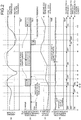
power supply device 100 according to the present embodiment is described next with reference toFIGS. 2. FIGS. 2 are diagrams illustrating an example of time charts of the station-building power supply device according to the present embodiment. -
FIG. 2(a) illustrates transition of the feeding voltage andFIG. 2(b) illustrates transition of charge/discharge power of thecapacitor unit 9.FIG. 2(c) illustrates transition of the SOC of thecapacitor unit 9, andFIG. 2(d) illustrates power consumption by thestation loads 4. The example illustrated inFIGS. 2 is an example in which a constant power charging method is used as a method of charging thecapacitor unit 9. In the illustrated example, discharging from thecapacitor unit 9 to thefeeder 6 is also performed at a constant power. The present invention is not limited by the method of charging thecapacitor unit 9 or the method of discharging from thecapacitor unit 9 to thefeeder 6. - In the period from a time t1 to a time t2, the feeding voltage is within a range from the second voltage threshold to the first voltage threshold (
FIG. 2(a) ) and the SOC of thecapacitor unit 9 is above the first SOC threshold (FIG. 2(c) ). Therefore, thecontrol unit 13 operates the secondpower conversion unit 12 such that it turns ON discharging from thecapacitor unit 9 to thestation loads 4. At that time, thecontrol unit 13 controls the secondpower conversion unit 12 such that it causes the amount of power supplied from thecapacitor unit 9 to thestation loads 4 to be substantially constant (FIG. 2(b) ). - When the SOC of the
capacitor unit 9 gradually decreases and the SOC of thecapacitor unit 9 falls below the first SOC threshold at the time t2 (FIG. 2(c) ), thecontrol unit 13 gradually decreases the amount of power supplied from thecapacitor unit 9 to thestation loads 4, causing the power amount supplied from thecapacitor unit 9 to thestation loads 4 to be substantially zero at a time t2', and stops the operation of the secondpower conversion unit 12 such that the discharging from thecapacitor unit 9 to thestation loads 4 is turned off. - When the feeding voltage exceeds the first voltage threshold at a time t3 (
FIG. 2(a) ), thecontrol unit 13 operates the firstpower conversion unit 11 such that it turns ON charging from thefeeder 6 to thecapacitor unit 9. When the SOC of thecapacitor unit 9 thereafter exceeds the first SOC threshold at a time t3', thecontrol unit 13 operates the secondpower conversion unit 12 such that it turns ON discharging from thecapacitor unit 9 to the station loads 4 to gradually increase the power amount supplied from thecapacitor unit 9 to the station loads 4 and controls the secondpower conversion unit 12 such that it causes the power amount supplied from thecapacitor unit 9 to the station loads 4 to be substantially constant after a time t3" (FIG. 2(b) ). - In the period from the time t3 to time t4, the SOC of the
capacitor unit 9 increases due to charging from thefeeder 6 to the capacitor unit 9 (FIG. 2(c) ). Meanwhile, the feeding value becomes lower (indicated by a solid line inFIG. 2(a) ) than that in a case where the charging to thecapacitor unit 9 is not performed (indicated by a dashed line inFIG. 2(a) ). - When the feeding voltage falls below the first voltage threshold at the time t4 (
FIG. 2(a) ), thecontrol unit 13 stops the operation of the firstpower conversion unit 11 so as to turn OFF the charging from thefeeder 6 to thecapacitor unit 9. - In the period from a time t5 to time t6, while the feeding voltage is below the first voltage threshold, discharging from the
capacitor unit 9 to thefeeder 6 is not performed because the SOC of thecapacitor unit 9 is below the second SOC threshold. That is, in the period from the time t4 to time t7, only discharging from thecapacitor unit 9 to the station loads 4 is performed and thus the SOC of thecapacitor unit 9 gradually decreases (FIG. 2(c) ). - When the feeding voltage exceeds the first voltage threshold at the time t7 (
FIG. 2(a) ), thecontrol unit 13 operates the firstpower conversion unit 11 such that it turns ON charging from thefeeder 6 to thecapacitor unit 9. - In the period from the time t7 to time t8, the charging from the
feeder 6 to thecapacitor unit 9 is performed similar to in the period from the time t3 to the time t4 and thus the SOC of thecapacitor unit 9 increases (FIG. 2(c) ). The feeding voltage accordingly becomes lower (indicated by a solid line inFIG. 2(a) ) than that in a case where the charging of thecapacitor unit 9 is not performed (indicated by a dashed line inFIG. 2(a) ). - When the feeding voltage falls below the first voltage threshold at the time t8 (
FIG. 2(a) ), thecontrol unit 13 stops the operation of the firstpower conversion unit 11 such that it turns OFF the charging from thefeeder 6 to thecapacitor unit 9. - In the period from the time t8 to a time t9, the feeding voltage is within the range from the second voltage threshold to the first voltage threshold (
FIG. 2(a) ) and the SOC of thecapacitor unit 9 is above the first SOC threshold (FIG. 2(c) ). Therefore, only discharging from thecapacitor unit 9 to the station loads 4 is performed and thus the SOC of thecapacitor unit 9 gradually decreases (FIG. 2(c) ). - When the feeding voltage falls below the second voltage threshold at the time t9 (
FIG. 2(a) ), thecontrol unit 13 operates the firstpower conversion unit 11 to turn ON discharging from thecapacitor unit 9 to thefeeder 6. - In the period from the time t9 to time t10, the feeding voltage is below the second voltage threshold (
FIG. 2(a) ) and the SOC of thecapacitor unit 9 is above the second SOC threshold (FIG. 2(c) ) unlike in the period from the time t5 to the time t6. Therefore, the discharging from thecapacitor unit 9 to the station loads 4 and discharging from thecapacitor unit 9 to thefeeder 6 are performed simultaneously, so that the SOC of thecapacitor unit 9 decreases more (FIG. 2(c) ) and the feeding voltage becomes higher (indicated by a solid line inFIG. 2(a) ) than that in a case where discharging to thecapacitor unit 9 is not performed (indicated by a dashed line inFIG. 2(a) ). - When the SOC of the
capacitor unit 9 falls below the second SOC threshold at the time t10 (FIG. 2(c) ), thecontrol unit 13 stops the operation of the firstpower conversion unit 11 to turn OFF the discharging from thecapacitor unit 9 to thefeeder 6. - In the period from the time t10 to a time t11, while the feeding voltage is below the first voltage threshold (
FIG. 2(a) ), discharging from thecapacitor unit 9 to thefeeder 6 is not performed because the SOC of thecapacitor unit 9 is below the second SOC threshold (FIG. 2(C) ). That is, in the period from the time t10 to a time t12, only the discharging from thecapacitor unit 9 to the station loads 4 is performed similar to in the period from the time t4 to the time t7 and thus the SOC of thecapacitor unit 9 gradually decreases (FIG. 2(c) ). - When the feeding voltage exceeds the first voltage threshold at the time t12 (
FIG. 2(a) ), thecontrol unit 13 operates the firstpower conversion unit 11 to turn ON charging from thefeeder 6 to thecapacitor unit 9. - After the time t12, charging from the
feeder 6 to thecapacitor unit 9 is performed similar to in the period from the time t3 to the time t4, so that the SOC of thecapacitor unit 9 increases (FIG. 2(c) ) and the feeding voltage becomes lower (indicated by a solid line inFIG. 2(a) ) than that in a case where the charging to thecapacitor unit 9 is not performed (indicated by a dashed line inFIG. 2(a) ). - In this way, in the example illustrated in
FIGS. 2 , surplus regenerative power, which has been charge in thecapacitor unit 9 in a period in which the feeding voltage is above the first voltage threshold, is supplied to the station loads 4 at a substantially constant power amount, except for a period in which the SOC of thecapacitor unit 9 is below the first SOC threshold. - A conventional configuration not including a capacitor unit that stores therein surplus regenerative power is described next.
FIGS. 3 are diagrams illustrating an example of time charts of a conventional station-building power supply device not including a capacitor unit that stores therein surplus regenerative power.FIG. 3(a) illustrates transition of a feeding voltage andFIG. 3(b) illustrates power consumption of station loads. - In the conventional configuration illustrated in
FIGS. 3 , only when the feeding voltage exceeds a voltage threshold, that is, only when surplus regenerative power occurs, the power from a feeder is supplied to the station loads and thus the amount of power supplied from an AC system fluctuates intermittently. Accordingly, even when the power supplied from the feeder is equal to or below the power consumption amount of the station loads, the total power amount of the AC system fluctuates intermittently, which may cause fluctuations in the AC system voltage. - In the configuration according to the present embodiment, the surplus regenerative power occurring intermittently is stored in the
capacitor unit 9 and power supplied continuously from theAC system 1 to the station loads 4 is supplemented with the surplus regenerative power stored in thecapacitor unit 9, in a period in which thecapacitor unit 9 maintains an SOC that enables discharging. Therefore, the surplus regenerative power can be effectively used while fluctuations in the total power amount of theAC system 1 are suppressed. - As described above, the station-building power supply device according to the present embodiment includes the capacitor unit that stores therein surplus regenerative power in an electrical transformation zone; the first power conversion unit that performs DC/DC power conversion in both directions between the feeder and the capacitor unit; and the second power conversion unit that converts DC power supplied from the capacitor unit to AC power to be supplied to the station loads. A voltage threshold (a first voltage threshold) for the feeding voltage and an SOC threshold (a first SOC threshold) for the SOC of the capacitor unit are set; a value that indicates occurrence of surplus regenerative power in the electrical transformation zone is set as the first voltage threshold; and a value that indicates whether the capacitor unit can discharge is set as the first SOC threshold. The first power conversion unit is controlled so as to supply power from the feeder to the capacitor unit to perform charging of the capacitor unit when the feeding voltage exceeds the first voltage threshold; and the second power conversion unit is controlled so as to supply power from the capacitor unit to the station loads when the SOC of the capacitor unit exceeds the first SOC threshold. Therefore, each time generation of surplus regenerative power in the electrical transformation zone occurs, the capacitor unit is charged with the surplus regenerative power, and power supplied continuously from the AC system to the station loads can be supplemented with the surplus regenerative power with which the capacitor unit has been charged in a period in which the capacitor unit maintains an SOC that enables discharging. Accordingly, the surplus regenerative power can be effectively used while fluctuations in the voltage of the feeder and fluctuations in the amount of power supplied from the AC system are suppressed.
- The second power conversion unit is controlled so as to cause the amount of power supplied from the capacitor unit to the station loads to be substantially constant. Accordingly, the amount of power supplied from the AC system can be more stable.
- Furthermore, the second voltage threshold smaller than the first voltage threshold is provided for the feeding voltage, and the second SOC threshold larger than the first SOC threshold is provided for the SOC of the capacitor unit. A value that indicates a shortage of power in the electrical transformation zone is set as the second voltage threshold, and a value that indicates whether the capacitor unit can supplement a power shortage in the electrical transformation zone is set as the second SOC threshold. When the feeding voltage falls below the second voltage threshold and the SOC of the capacitor unit exceeds the second SOC threshold, the first power conversion unit is controlled such that the power is supplied from the capacitor unit to the feeder. Therefore, in a period in which the capacitor unit maintains an SOC that enables supplementation of a power shortage in the electrical transformation zone, the power shortage in the electrical transformation zone can be supplemented with surplus regenerative power with which the capacitor unit has been charged. Accordingly, voltage fluctuations of the feeder can be more stable.
- The configuration described in the above embodiment is only an example of the contents of the present invention. The configuration can be combined with other well-known techniques, and it is needless to mention that the present invention can be configured while modifying it without departing from the scope of the invention.
- 1 AC system, 2 station building, 3 transformer, 4, 4-1, 4-2, ..., 4-n station load, 5 train, 6 feeder, 7 rail, 8 feeding-voltage detection unit, 9 capacitor unit, 10 SOC detection unit, 11 first power conversion unit, 12 second power conversion unit, 13 control unit, 21 bidirectional DC/DC converter, 22 inverter, 23 transformer, 100 station-building power supply device.
Claims (1)
- A station-building power supply device (100) that supplies power to a station load (4) using both AC power supplied from an AC system(1) and surplus regenerative power generated by trains (5), the station-building power supply device(100) comprising:a feeding-voltage detection unit (8) that detects a feeding voltage;an SOC (State Of Charge) detection unit (10) that detects an SOC of a capacitor unit (9) that stores therein the surplus regenerative power;a first power conversion unit (11) that performs DC/DC power conversion in both directions between a feeder (6) and the capacitor unit (9) ;a second power conversion unit (12) that converts DC power supplied from the capacitor unit (9) to AC power and supplies the AC power to the station load(4); anda control unit (13) that controls the first power conversion unit (11) and the second power conversion unit (12) on the basis of the feeding voltage and the SOC, whereinthe control unit (13) controls, when the SOC exceeds a predetermined first SOC threshold, the second power conversion unit (12) such that power is supplied from the capacitor unit (9) to the station load (4), andcontrols, when the SOC exceeds a second SOC threshold that is larger than the first SOC threshold, the first power conversion unit (11) such that power is supplied from the capacitor unit (9) to the feeder (6).
Priority Applications (1)
| Application Number | Priority Date | Filing Date | Title |
|---|---|---|---|
| EP17193969.7A EP3281820B1 (en) | 2013-11-28 | 2013-11-28 | Station building power supply device |
Applications Claiming Priority (3)
| Application Number | Priority Date | Filing Date | Title |
|---|---|---|---|
| EP17193969.7A EP3281820B1 (en) | 2013-11-28 | 2013-11-28 | Station building power supply device |
| EP13898230.1A EP3075596B1 (en) | 2013-11-28 | 2013-11-28 | Station building power supply device |
| PCT/JP2013/082109 WO2015079544A1 (en) | 2013-11-28 | 2013-11-28 | Station building power supply device |
Related Parent Applications (2)
| Application Number | Title | Priority Date | Filing Date |
|---|---|---|---|
| EP13898230.1A Division EP3075596B1 (en) | 2013-11-28 | 2013-11-28 | Station building power supply device |
| EP13898230.1A Division-Into EP3075596B1 (en) | 2013-11-28 | 2013-11-28 | Station building power supply device |
Publications (2)
| Publication Number | Publication Date |
|---|---|
| EP3281820A1 EP3281820A1 (en) | 2018-02-14 |
| EP3281820B1 true EP3281820B1 (en) | 2020-03-04 |
Family
ID=53198533
Family Applications (3)
| Application Number | Title | Priority Date | Filing Date |
|---|---|---|---|
| EP17193969.7A Active EP3281820B1 (en) | 2013-11-28 | 2013-11-28 | Station building power supply device |
| EP19179076.5A Active EP3556604B1 (en) | 2013-11-28 | 2013-11-28 | Station building power supply device |
| EP13898230.1A Active EP3075596B1 (en) | 2013-11-28 | 2013-11-28 | Station building power supply device |
Family Applications After (2)
| Application Number | Title | Priority Date | Filing Date |
|---|---|---|---|
| EP19179076.5A Active EP3556604B1 (en) | 2013-11-28 | 2013-11-28 | Station building power supply device |
| EP13898230.1A Active EP3075596B1 (en) | 2013-11-28 | 2013-11-28 | Station building power supply device |
Country Status (5)
| Country | Link |
|---|---|
| US (1) | US10020653B2 (en) |
| EP (3) | EP3281820B1 (en) |
| CN (1) | CN105764743B (en) |
| AU (1) | AU2013406324B2 (en) |
| WO (1) | WO2015079544A1 (en) |
Families Citing this family (5)
| Publication number | Priority date | Publication date | Assignee | Title |
|---|---|---|---|---|
| FR3031849B1 (en) | 2015-01-16 | 2017-02-17 | Alstom Transp Tech | POWER SUPPLY CONVERTER AND / OR SUBSTATION FOR RECOVERING BRAKING ENERGY |
| WO2017060444A1 (en) * | 2015-10-07 | 2017-04-13 | Abb Schweiz Ag | Arrangement and method for transforming a voltage |
| JP6501976B2 (en) * | 2016-07-04 | 2019-04-17 | 三菱電機株式会社 | Station building power supply device and charge detection method |
| DE102017105728A1 (en) * | 2017-03-16 | 2018-09-20 | Fraunhofer-Gesellschaft zur Förderung der angewandten Forschung e.V. | Device for supplying energy to an electrical network |
| WO2020194697A1 (en) * | 2019-03-28 | 2020-10-01 | 三菱電機株式会社 | Station building auxiliary power supply device |
Citations (1)
| Publication number | Priority date | Publication date | Assignee | Title |
|---|---|---|---|---|
| JP2013023074A (en) * | 2011-07-21 | 2013-02-04 | Hitachi Ltd | Railway feeding system |
Family Cites Families (18)
| Publication number | Priority date | Publication date | Assignee | Title |
|---|---|---|---|---|
| JP2001347857A (en) * | 2000-06-08 | 2001-12-18 | Fuji Electric Co Ltd | Inverter for electric power regeneration and its starting method |
| JP3964857B2 (en) | 2003-12-04 | 2007-08-22 | 株式会社日立製作所 | Regenerative power absorption control method for electric railways |
| JP4432675B2 (en) | 2004-08-25 | 2010-03-17 | 株式会社日立製作所 | Power converter |
| DE102006062424B4 (en) * | 2006-12-27 | 2009-02-12 | Siemens Ag | Method for regenerating electrical energy of rail vehicles |
| FR2915435B1 (en) | 2007-04-25 | 2009-08-07 | Alstom Transport Sa | SYSTEM, SUBSTATION AND METHOD FOR RECOVERING THE BRAKING ENERGY OF RAILWAY VEHICLES, RAILWAY VEHICLES FOR THIS SYSTEM. |
| RU2465157C2 (en) | 2008-02-29 | 2012-10-27 | Кавасаки Дзукогио Кабусики Кайся | Electric supply system for electric railway |
| JP2009241677A (en) * | 2008-03-31 | 2009-10-22 | Railway Technical Res Inst | Control system of power storage device of dc electric railroad vehicle |
| JP2010000810A (en) | 2008-06-18 | 2010-01-07 | Meidensha Corp | Feeder system of dc feeding network |
| JP5187624B2 (en) | 2008-06-30 | 2013-04-24 | 川崎重工業株式会社 | Microgrid using electric railway system |
| JP2010098866A (en) | 2008-10-17 | 2010-04-30 | Panasonic Corp | Imbalance determination circuit, imbalance reduction circuit, battery power supply, and imbalance evaluation method |
| US20120047386A1 (en) * | 2009-04-30 | 2012-02-23 | Ryoji Matsui | Control apparatus and control method |
| JP2011126370A (en) | 2009-12-16 | 2011-06-30 | Kawasaki Heavy Ind Ltd | Power supply system and power supply method |
| JP5377538B2 (en) * | 2011-02-14 | 2013-12-25 | 株式会社東芝 | Power storage device and its installation / operation method |
| US20140055080A1 (en) * | 2011-04-22 | 2014-02-27 | Mitsubishi Electric Corporation | Charging apparatus |
| CN102267405B (en) * | 2011-05-09 | 2013-11-06 | 株洲变流技术国家工程研究中心有限公司 | Energy feeding type dragging power supply device and control method thereof |
| JP5752562B2 (en) * | 2011-11-01 | 2015-07-22 | 公益財団法人鉄道総合技術研究所 | Control system for power storage device for DC electric railway |
| CN104584378B (en) * | 2012-08-29 | 2017-12-05 | 三菱电机株式会社 | Station supply unit and its control method |
| WO2014038020A1 (en) * | 2012-09-05 | 2014-03-13 | 三菱電機株式会社 | Station building power supply device |
-
2013
- 2013-11-28 EP EP17193969.7A patent/EP3281820B1/en active Active
- 2013-11-28 US US15/032,429 patent/US10020653B2/en active Active
- 2013-11-28 EP EP19179076.5A patent/EP3556604B1/en active Active
- 2013-11-28 EP EP13898230.1A patent/EP3075596B1/en active Active
- 2013-11-28 WO PCT/JP2013/082109 patent/WO2015079544A1/en active Application Filing
- 2013-11-28 AU AU2013406324A patent/AU2013406324B2/en active Active
- 2013-11-28 CN CN201380081218.8A patent/CN105764743B/en active Active
Patent Citations (1)
| Publication number | Priority date | Publication date | Assignee | Title |
|---|---|---|---|---|
| JP2013023074A (en) * | 2011-07-21 | 2013-02-04 | Hitachi Ltd | Railway feeding system |
Also Published As
| Publication number | Publication date |
|---|---|
| AU2013406324B2 (en) | 2016-12-15 |
| EP3556604A1 (en) | 2019-10-23 |
| CN105764743B (en) | 2018-11-09 |
| AU2013406324A1 (en) | 2016-05-19 |
| US10020653B2 (en) | 2018-07-10 |
| EP3075596B1 (en) | 2020-04-01 |
| WO2015079544A1 (en) | 2015-06-04 |
| EP3075596A4 (en) | 2017-06-21 |
| CN105764743A (en) | 2016-07-13 |
| US20160268803A1 (en) | 2016-09-15 |
| EP3075596A1 (en) | 2016-10-05 |
| EP3556604B1 (en) | 2021-07-28 |
| EP3281820A1 (en) | 2018-02-14 |
Similar Documents
| Publication | Publication Date | Title |
|---|---|---|
| JP6004833B2 (en) | Station building power supply | |
| EP3281820B1 (en) | Station building power supply device | |
| US9873335B2 (en) | Electric railcar power feeding system, power feeding device, and power storage device | |
| CN103874649B (en) | The regeneration storage battery control setup of elevator | |
| JP5752562B2 (en) | Control system for power storage device for DC electric railway | |
| KR20160038348A (en) | Device for low voltage dc-dc converter-integrated charger | |
| CN206807115U (en) | A kind of data center's electric power system based on super capacitor energy-storage | |
| CN103010868A (en) | Elevator energy-saving system and control method thereof | |
| EP3246195B1 (en) | Charge/discharge control device | |
| US10372101B2 (en) | Station auxiliary power source apparatus | |
| JP6870678B2 (en) | Power storage system | |
| JP2006062427A (en) | Power converter, power conversion system, and its controlling method | |
| EP3088241B1 (en) | Regeneration inverter device for electric railroad | |
| JP5509442B2 (en) | Power converter and electric railway system | |
| JP6504789B2 (en) | Power converter | |
| JP2015167466A (en) | Driving device for railway vehicle | |
| JP2015107766A (en) | Station power supply | |
| CN111231669A (en) | Vehicle-mounted charger, power supply system of electric vehicle and electric vehicle | |
| CN210053247U (en) | Elevator emergency power supply system adopting bidirectional DC/AC | |
| CN110140273A (en) | DC power-supply system | |
| JP5069363B1 (en) | Charger | |
| JP6539174B2 (en) | Railway train system | |
| CN116111818A (en) | High-voltage bus capacitor discharging device and vehicle | |
| WO2016139812A1 (en) | Station power-source device | |
| JP2017077857A (en) | Method and device for controlling electric railroad regenerative inverter |
Legal Events
| Date | Code | Title | Description |
|---|---|---|---|
| PUAI | Public reference made under article 153(3) epc to a published international application that has entered the european phase |
Free format text: ORIGINAL CODE: 0009012 |
|
| STAA | Information on the status of an ep patent application or granted ep patent |
Free format text: STATUS: THE APPLICATION HAS BEEN PUBLISHED |
|
| AC | Divisional application: reference to earlier application |
Ref document number: 3075596 Country of ref document: EP Kind code of ref document: P |
|
| AK | Designated contracting states |
Kind code of ref document: A1 Designated state(s): AL AT BE BG CH CY CZ DE DK EE ES FI FR GB GR HR HU IE IS IT LI LT LU LV MC MK MT NL NO PL PT RO RS SE SI SK SM TR |
|
| STAA | Information on the status of an ep patent application or granted ep patent |
Free format text: STATUS: REQUEST FOR EXAMINATION WAS MADE |
|
| 17P | Request for examination filed |
Effective date: 20180614 |
|
| RBV | Designated contracting states (corrected) |
Designated state(s): AL AT BE BG CH CY CZ DE DK EE ES FI FR GB GR HR HU IE IS IT LI LT LU LV MC MK MT NL NO PL PT RO RS SE SI SK SM TR |
|
| STAA | Information on the status of an ep patent application or granted ep patent |
Free format text: STATUS: EXAMINATION IS IN PROGRESS |
|
| 17Q | First examination report despatched |
Effective date: 20190130 |
|
| GRAP | Despatch of communication of intention to grant a patent |
Free format text: ORIGINAL CODE: EPIDOSNIGR1 |
|
| STAA | Information on the status of an ep patent application or granted ep patent |
Free format text: STATUS: GRANT OF PATENT IS INTENDED |
|
| INTG | Intention to grant announced |
Effective date: 20190913 |
|
| GRAS | Grant fee paid |
Free format text: ORIGINAL CODE: EPIDOSNIGR3 |
|
| GRAA | (expected) grant |
Free format text: ORIGINAL CODE: 0009210 |
|
| STAA | Information on the status of an ep patent application or granted ep patent |
Free format text: STATUS: THE PATENT HAS BEEN GRANTED |
|
| AC | Divisional application: reference to earlier application |
Ref document number: 3075596 Country of ref document: EP Kind code of ref document: P |
|
| AK | Designated contracting states |
Kind code of ref document: B1 Designated state(s): AL AT BE BG CH CY CZ DE DK EE ES FI FR GB GR HR HU IE IS IT LI LT LU LV MC MK MT NL NO PL PT RO RS SE SI SK SM TR |
|
| REG | Reference to a national code |
Ref country code: GB Ref legal event code: FG4D |
|
| REG | Reference to a national code |
Ref country code: CH Ref legal event code: EP |
|
| REG | Reference to a national code |
Ref country code: AT Ref legal event code: REF Ref document number: 1239987 Country of ref document: AT Kind code of ref document: T Effective date: 20200315 |
|
| REG | Reference to a national code |
Ref country code: DE Ref legal event code: R096 Ref document number: 602013066584 Country of ref document: DE |
|
| REG | Reference to a national code |
Ref country code: IE Ref legal event code: FG4D |
|
| PG25 | Lapsed in a contracting state [announced via postgrant information from national office to epo] |
Ref country code: NO Free format text: LAPSE BECAUSE OF FAILURE TO SUBMIT A TRANSLATION OF THE DESCRIPTION OR TO PAY THE FEE WITHIN THE PRESCRIBED TIME-LIMIT Effective date: 20200604 Ref country code: FI Free format text: LAPSE BECAUSE OF FAILURE TO SUBMIT A TRANSLATION OF THE DESCRIPTION OR TO PAY THE FEE WITHIN THE PRESCRIBED TIME-LIMIT Effective date: 20200304 Ref country code: RS Free format text: LAPSE BECAUSE OF FAILURE TO SUBMIT A TRANSLATION OF THE DESCRIPTION OR TO PAY THE FEE WITHIN THE PRESCRIBED TIME-LIMIT Effective date: 20200304 |
|
| REG | Reference to a national code |
Ref country code: NL Ref legal event code: MP Effective date: 20200304 |
|
| PG25 | Lapsed in a contracting state [announced via postgrant information from national office to epo] |
Ref country code: BG Free format text: LAPSE BECAUSE OF FAILURE TO SUBMIT A TRANSLATION OF THE DESCRIPTION OR TO PAY THE FEE WITHIN THE PRESCRIBED TIME-LIMIT Effective date: 20200604 Ref country code: LV Free format text: LAPSE BECAUSE OF FAILURE TO SUBMIT A TRANSLATION OF THE DESCRIPTION OR TO PAY THE FEE WITHIN THE PRESCRIBED TIME-LIMIT Effective date: 20200304 Ref country code: SE Free format text: LAPSE BECAUSE OF FAILURE TO SUBMIT A TRANSLATION OF THE DESCRIPTION OR TO PAY THE FEE WITHIN THE PRESCRIBED TIME-LIMIT Effective date: 20200304 Ref country code: HR Free format text: LAPSE BECAUSE OF FAILURE TO SUBMIT A TRANSLATION OF THE DESCRIPTION OR TO PAY THE FEE WITHIN THE PRESCRIBED TIME-LIMIT Effective date: 20200304 Ref country code: GR Free format text: LAPSE BECAUSE OF FAILURE TO SUBMIT A TRANSLATION OF THE DESCRIPTION OR TO PAY THE FEE WITHIN THE PRESCRIBED TIME-LIMIT Effective date: 20200605 |
|
| REG | Reference to a national code |
Ref country code: LT Ref legal event code: MG4D |
|
| PG25 | Lapsed in a contracting state [announced via postgrant information from national office to epo] |
Ref country code: NL Free format text: LAPSE BECAUSE OF FAILURE TO SUBMIT A TRANSLATION OF THE DESCRIPTION OR TO PAY THE FEE WITHIN THE PRESCRIBED TIME-LIMIT Effective date: 20200304 |
|
| PG25 | Lapsed in a contracting state [announced via postgrant information from national office to epo] |
Ref country code: CZ Free format text: LAPSE BECAUSE OF FAILURE TO SUBMIT A TRANSLATION OF THE DESCRIPTION OR TO PAY THE FEE WITHIN THE PRESCRIBED TIME-LIMIT Effective date: 20200304 Ref country code: IS Free format text: LAPSE BECAUSE OF FAILURE TO SUBMIT A TRANSLATION OF THE DESCRIPTION OR TO PAY THE FEE WITHIN THE PRESCRIBED TIME-LIMIT Effective date: 20200704 Ref country code: RO Free format text: LAPSE BECAUSE OF FAILURE TO SUBMIT A TRANSLATION OF THE DESCRIPTION OR TO PAY THE FEE WITHIN THE PRESCRIBED TIME-LIMIT Effective date: 20200304 Ref country code: SK Free format text: LAPSE BECAUSE OF FAILURE TO SUBMIT A TRANSLATION OF THE DESCRIPTION OR TO PAY THE FEE WITHIN THE PRESCRIBED TIME-LIMIT Effective date: 20200304 Ref country code: PT Free format text: LAPSE BECAUSE OF FAILURE TO SUBMIT A TRANSLATION OF THE DESCRIPTION OR TO PAY THE FEE WITHIN THE PRESCRIBED TIME-LIMIT Effective date: 20200729 Ref country code: LT Free format text: LAPSE BECAUSE OF FAILURE TO SUBMIT A TRANSLATION OF THE DESCRIPTION OR TO PAY THE FEE WITHIN THE PRESCRIBED TIME-LIMIT Effective date: 20200304 Ref country code: SM Free format text: LAPSE BECAUSE OF FAILURE TO SUBMIT A TRANSLATION OF THE DESCRIPTION OR TO PAY THE FEE WITHIN THE PRESCRIBED TIME-LIMIT Effective date: 20200304 Ref country code: EE Free format text: LAPSE BECAUSE OF FAILURE TO SUBMIT A TRANSLATION OF THE DESCRIPTION OR TO PAY THE FEE WITHIN THE PRESCRIBED TIME-LIMIT Effective date: 20200304 Ref country code: ES Free format text: LAPSE BECAUSE OF FAILURE TO SUBMIT A TRANSLATION OF THE DESCRIPTION OR TO PAY THE FEE WITHIN THE PRESCRIBED TIME-LIMIT Effective date: 20200304 |
|
| REG | Reference to a national code |
Ref country code: AT Ref legal event code: MK05 Ref document number: 1239987 Country of ref document: AT Kind code of ref document: T Effective date: 20200304 |
|
| REG | Reference to a national code |
Ref country code: DE Ref legal event code: R097 Ref document number: 602013066584 Country of ref document: DE |
|
| PLBE | No opposition filed within time limit |
Free format text: ORIGINAL CODE: 0009261 |
|
| STAA | Information on the status of an ep patent application or granted ep patent |
Free format text: STATUS: NO OPPOSITION FILED WITHIN TIME LIMIT |
|
| PG25 | Lapsed in a contracting state [announced via postgrant information from national office to epo] |
Ref country code: DK Free format text: LAPSE BECAUSE OF FAILURE TO SUBMIT A TRANSLATION OF THE DESCRIPTION OR TO PAY THE FEE WITHIN THE PRESCRIBED TIME-LIMIT Effective date: 20200304 Ref country code: AT Free format text: LAPSE BECAUSE OF FAILURE TO SUBMIT A TRANSLATION OF THE DESCRIPTION OR TO PAY THE FEE WITHIN THE PRESCRIBED TIME-LIMIT Effective date: 20200304 Ref country code: IT Free format text: LAPSE BECAUSE OF FAILURE TO SUBMIT A TRANSLATION OF THE DESCRIPTION OR TO PAY THE FEE WITHIN THE PRESCRIBED TIME-LIMIT Effective date: 20200304 |
|
| 26N | No opposition filed |
Effective date: 20201207 |
|
| PG25 | Lapsed in a contracting state [announced via postgrant information from national office to epo] |
Ref country code: PL Free format text: LAPSE BECAUSE OF FAILURE TO SUBMIT A TRANSLATION OF THE DESCRIPTION OR TO PAY THE FEE WITHIN THE PRESCRIBED TIME-LIMIT Effective date: 20200304 Ref country code: SI Free format text: LAPSE BECAUSE OF FAILURE TO SUBMIT A TRANSLATION OF THE DESCRIPTION OR TO PAY THE FEE WITHIN THE PRESCRIBED TIME-LIMIT Effective date: 20200304 |
|
| PG25 | Lapsed in a contracting state [announced via postgrant information from national office to epo] |
Ref country code: MC Free format text: LAPSE BECAUSE OF FAILURE TO SUBMIT A TRANSLATION OF THE DESCRIPTION OR TO PAY THE FEE WITHIN THE PRESCRIBED TIME-LIMIT Effective date: 20200304 |
|
| REG | Reference to a national code |
Ref country code: CH Ref legal event code: PL |
|
| GBPC | Gb: european patent ceased through non-payment of renewal fee |
Effective date: 20201128 |
|
| PG25 | Lapsed in a contracting state [announced via postgrant information from national office to epo] |
Ref country code: LU Free format text: LAPSE BECAUSE OF NON-PAYMENT OF DUE FEES Effective date: 20201128 |
|
| REG | Reference to a national code |
Ref country code: BE Ref legal event code: MM Effective date: 20201130 |
|
| PG25 | Lapsed in a contracting state [announced via postgrant information from national office to epo] |
Ref country code: LI Free format text: LAPSE BECAUSE OF NON-PAYMENT OF DUE FEES Effective date: 20201130 Ref country code: CH Free format text: LAPSE BECAUSE OF NON-PAYMENT OF DUE FEES Effective date: 20201130 |
|
| PG25 | Lapsed in a contracting state [announced via postgrant information from national office to epo] |
Ref country code: IE Free format text: LAPSE BECAUSE OF NON-PAYMENT OF DUE FEES Effective date: 20201128 |
|
| PG25 | Lapsed in a contracting state [announced via postgrant information from national office to epo] |
Ref country code: GB Free format text: LAPSE BECAUSE OF NON-PAYMENT OF DUE FEES Effective date: 20201128 |
|
| PG25 | Lapsed in a contracting state [announced via postgrant information from national office to epo] |
Ref country code: MT Free format text: LAPSE BECAUSE OF FAILURE TO SUBMIT A TRANSLATION OF THE DESCRIPTION OR TO PAY THE FEE WITHIN THE PRESCRIBED TIME-LIMIT Effective date: 20200304 Ref country code: CY Free format text: LAPSE BECAUSE OF FAILURE TO SUBMIT A TRANSLATION OF THE DESCRIPTION OR TO PAY THE FEE WITHIN THE PRESCRIBED TIME-LIMIT Effective date: 20200304 |
|
| PG25 | Lapsed in a contracting state [announced via postgrant information from national office to epo] |
Ref country code: MK Free format text: LAPSE BECAUSE OF FAILURE TO SUBMIT A TRANSLATION OF THE DESCRIPTION OR TO PAY THE FEE WITHIN THE PRESCRIBED TIME-LIMIT Effective date: 20200304 Ref country code: AL Free format text: LAPSE BECAUSE OF FAILURE TO SUBMIT A TRANSLATION OF THE DESCRIPTION OR TO PAY THE FEE WITHIN THE PRESCRIBED TIME-LIMIT Effective date: 20200304 |
|
| PG25 | Lapsed in a contracting state [announced via postgrant information from national office to epo] |
Ref country code: BE Free format text: LAPSE BECAUSE OF NON-PAYMENT OF DUE FEES Effective date: 20201130 |
|
| REG | Reference to a national code |
Ref country code: DE Ref legal event code: R084 Ref document number: 602013066584 Country of ref document: DE |
|
| P01 | Opt-out of the competence of the unified patent court (upc) registered |
Effective date: 20230512 |
|
| PGFP | Annual fee paid to national office [announced via postgrant information from national office to epo] |
Ref country code: FR Payment date: 20230929 Year of fee payment: 11 |
|
| PGFP | Annual fee paid to national office [announced via postgrant information from national office to epo] |
Ref country code: TR Payment date: 20231124 Year of fee payment: 11 Ref country code: DE Payment date: 20231003 Year of fee payment: 11 |