EP3280676B1 - Leveling system for lift device - Google Patents
Leveling system for lift device Download PDFInfo
- Publication number
- EP3280676B1 EP3280676B1 EP17718462.9A EP17718462A EP3280676B1 EP 3280676 B1 EP3280676 B1 EP 3280676B1 EP 17718462 A EP17718462 A EP 17718462A EP 3280676 B1 EP3280676 B1 EP 3280676B1
- Authority
- EP
- European Patent Office
- Prior art keywords
- actuator
- lift device
- axle
- leveling assembly
- chassis
- Prior art date
- Legal status (The legal status is an assumption and is not a legal conclusion. Google has not performed a legal analysis and makes no representation as to the accuracy of the status listed.)
- Active
Links
Images


Classifications
-
- B—PERFORMING OPERATIONS; TRANSPORTING
- B66—HOISTING; LIFTING; HAULING
- B66F—HOISTING, LIFTING, HAULING OR PUSHING, NOT OTHERWISE PROVIDED FOR, e.g. DEVICES WHICH APPLY A LIFTING OR PUSHING FORCE DIRECTLY TO THE SURFACE OF A LOAD
- B66F9/00—Devices for lifting or lowering bulky or heavy goods for loading or unloading purposes
-
- B—PERFORMING OPERATIONS; TRANSPORTING
- B60—VEHICLES IN GENERAL
- B60G—VEHICLE SUSPENSION ARRANGEMENTS
- B60G17/00—Resilient suspensions having means for adjusting the spring or vibration-damper characteristics, for regulating the distance between a supporting surface and a sprung part of vehicle or for locking suspension during use to meet varying vehicular or surface conditions, e.g. due to speed or load
- B60G17/015—Resilient suspensions having means for adjusting the spring or vibration-damper characteristics, for regulating the distance between a supporting surface and a sprung part of vehicle or for locking suspension during use to meet varying vehicular or surface conditions, e.g. due to speed or load the regulating means comprising electric or electronic elements
- B60G17/016—Resilient suspensions having means for adjusting the spring or vibration-damper characteristics, for regulating the distance between a supporting surface and a sprung part of vehicle or for locking suspension during use to meet varying vehicular or surface conditions, e.g. due to speed or load the regulating means comprising electric or electronic elements characterised by their responsiveness, when the vehicle is travelling, to specific motion, a specific condition, or driver input
-
- B—PERFORMING OPERATIONS; TRANSPORTING
- B60—VEHICLES IN GENERAL
- B60G—VEHICLE SUSPENSION ARRANGEMENTS
- B60G21/00—Interconnection systems for two or more resiliently-suspended wheels, e.g. for stabilising a vehicle body with respect to acceleration, deceleration or centrifugal forces
- B60G21/007—Interconnection systems for two or more resiliently-suspended wheels, e.g. for stabilising a vehicle body with respect to acceleration, deceleration or centrifugal forces means for adjusting the wheel inclination
-
- B—PERFORMING OPERATIONS; TRANSPORTING
- B60—VEHICLES IN GENERAL
- B60G—VEHICLE SUSPENSION ARRANGEMENTS
- B60G9/00—Resilient suspensions of a rigid axle or axle housing for two or more wheels
- B60G9/02—Resilient suspensions of a rigid axle or axle housing for two or more wheels the axle or housing being pivotally mounted on the vehicle, e.g. the pivotal axis being parallel to the longitudinal axis of the vehicle
-
- B—PERFORMING OPERATIONS; TRANSPORTING
- B60—VEHICLES IN GENERAL
- B60P—VEHICLES ADAPTED FOR LOAD TRANSPORTATION OR TO TRANSPORT, TO CARRY, OR TO COMPRISE SPECIAL LOADS OR OBJECTS
- B60P1/00—Vehicles predominantly for transporting loads and modified to facilitate loading, consolidating the load, or unloading
- B60P1/04—Vehicles predominantly for transporting loads and modified to facilitate loading, consolidating the load, or unloading with a tipping movement of load-transporting element
- B60P1/30—Vehicles predominantly for transporting loads and modified to facilitate loading, consolidating the load, or unloading with a tipping movement of load-transporting element in combination with another movement of the element
- B60P1/34—Vehicles predominantly for transporting loads and modified to facilitate loading, consolidating the load, or unloading with a tipping movement of load-transporting element in combination with another movement of the element the other movement being raising or lowering
-
- B—PERFORMING OPERATIONS; TRANSPORTING
- B66—HOISTING; LIFTING; HAULING
- B66C—CRANES; LOAD-ENGAGING ELEMENTS OR DEVICES FOR CRANES, CAPSTANS, WINCHES, OR TACKLES
- B66C9/00—Travelling gear incorporated in or fitted to trolleys or cranes
-
- B—PERFORMING OPERATIONS; TRANSPORTING
- B66—HOISTING; LIFTING; HAULING
- B66F—HOISTING, LIFTING, HAULING OR PUSHING, NOT OTHERWISE PROVIDED FOR, e.g. DEVICES WHICH APPLY A LIFTING OR PUSHING FORCE DIRECTLY TO THE SURFACE OF A LOAD
- B66F11/00—Lifting devices specially adapted for particular uses not otherwise provided for
- B66F11/04—Lifting devices specially adapted for particular uses not otherwise provided for for movable platforms or cabins, e.g. on vehicles, permitting workmen to place themselves in any desired position for carrying out required operations
- B66F11/044—Working platforms suspended from booms
-
- B—PERFORMING OPERATIONS; TRANSPORTING
- B66—HOISTING; LIFTING; HAULING
- B66F—HOISTING, LIFTING, HAULING OR PUSHING, NOT OTHERWISE PROVIDED FOR, e.g. DEVICES WHICH APPLY A LIFTING OR PUSHING FORCE DIRECTLY TO THE SURFACE OF A LOAD
- B66F13/00—Common constructional features or accessories
-
- B—PERFORMING OPERATIONS; TRANSPORTING
- B66—HOISTING; LIFTING; HAULING
- B66F—HOISTING, LIFTING, HAULING OR PUSHING, NOT OTHERWISE PROVIDED FOR, e.g. DEVICES WHICH APPLY A LIFTING OR PUSHING FORCE DIRECTLY TO THE SURFACE OF A LOAD
- B66F5/00—Mobile jacks of the garage type mounted on wheels or rollers
- B66F5/04—Mobile jacks of the garage type mounted on wheels or rollers with fluid-pressure-operated lifting gear
-
- B—PERFORMING OPERATIONS; TRANSPORTING
- B66—HOISTING; LIFTING; HAULING
- B66F—HOISTING, LIFTING, HAULING OR PUSHING, NOT OTHERWISE PROVIDED FOR, e.g. DEVICES WHICH APPLY A LIFTING OR PUSHING FORCE DIRECTLY TO THE SURFACE OF A LOAD
- B66F9/00—Devices for lifting or lowering bulky or heavy goods for loading or unloading purposes
- B66F9/06—Devices for lifting or lowering bulky or heavy goods for loading or unloading purposes movable, with their loads, on wheels or the like, e.g. fork-lift trucks
- B66F9/065—Devices for lifting or lowering bulky or heavy goods for loading or unloading purposes movable, with their loads, on wheels or the like, e.g. fork-lift trucks non-masted
-
- B—PERFORMING OPERATIONS; TRANSPORTING
- B66—HOISTING; LIFTING; HAULING
- B66F—HOISTING, LIFTING, HAULING OR PUSHING, NOT OTHERWISE PROVIDED FOR, e.g. DEVICES WHICH APPLY A LIFTING OR PUSHING FORCE DIRECTLY TO THE SURFACE OF A LOAD
- B66F9/00—Devices for lifting or lowering bulky or heavy goods for loading or unloading purposes
- B66F9/06—Devices for lifting or lowering bulky or heavy goods for loading or unloading purposes movable, with their loads, on wheels or the like, e.g. fork-lift trucks
- B66F9/075—Constructional features or details
- B66F9/07586—Suspension or mounting of wheels on chassis
-
- E—FIXED CONSTRUCTIONS
- E01—CONSTRUCTION OF ROADS, RAILWAYS, OR BRIDGES
- E01B—PERMANENT WAY; PERMANENT-WAY TOOLS; MACHINES FOR MAKING RAILWAYS OF ALL KINDS
- E01B27/00—Placing, renewing, working, cleaning, or taking-up the ballast, with or without concurrent work on the track; Devices therefor; Packing sleepers
- E01B27/12—Packing sleepers, with or without concurrent work on the track; Compacting track-carrying ballast
- E01B27/13—Packing sleepers, with or without concurrent work on the track
- E01B27/16—Sleeper-tamping machines
- E01B27/17—Sleeper-tamping machines combined with means for lifting, levelling or slewing the track
-
- E—FIXED CONSTRUCTIONS
- E02—HYDRAULIC ENGINEERING; FOUNDATIONS; SOIL SHIFTING
- E02F—DREDGING; SOIL-SHIFTING
- E02F9/00—Component parts of dredgers or soil-shifting machines, not restricted to one of the kinds covered by groups E02F3/00 - E02F7/00
- E02F9/02—Travelling-gear, e.g. associated with slewing gears
-
- B—PERFORMING OPERATIONS; TRANSPORTING
- B60—VEHICLES IN GENERAL
- B60G—VEHICLE SUSPENSION ARRANGEMENTS
- B60G2202/00—Indexing codes relating to the type of spring, damper or actuator
- B60G2202/40—Type of actuator
- B60G2202/41—Fluid actuator
- B60G2202/413—Hydraulic actuator
-
- B—PERFORMING OPERATIONS; TRANSPORTING
- B60—VEHICLES IN GENERAL
- B60G—VEHICLE SUSPENSION ARRANGEMENTS
- B60G2300/00—Indexing codes relating to the type of vehicle
- B60G2300/02—Trucks; Load vehicles
- B60G2300/022—Fork lift trucks, Clark
-
- B—PERFORMING OPERATIONS; TRANSPORTING
- B60—VEHICLES IN GENERAL
- B60G—VEHICLE SUSPENSION ARRANGEMENTS
- B60G2400/00—Indexing codes relating to detected, measured or calculated conditions or factors
- B60G2400/05—Attitude
- B60G2400/051—Angle
- B60G2400/0511—Roll angle
-
- B—PERFORMING OPERATIONS; TRANSPORTING
- B60—VEHICLES IN GENERAL
- B60G—VEHICLE SUSPENSION ARRANGEMENTS
- B60G2400/00—Indexing codes relating to detected, measured or calculated conditions or factors
- B60G2400/05—Attitude
- B60G2400/051—Angle
- B60G2400/0512—Pitch angle
-
- B—PERFORMING OPERATIONS; TRANSPORTING
- B60—VEHICLES IN GENERAL
- B60G—VEHICLE SUSPENSION ARRANGEMENTS
- B60G2400/00—Indexing codes relating to detected, measured or calculated conditions or factors
- B60G2400/25—Stroke; Height; Displacement
- B60G2400/252—Stroke; Height; Displacement vertical
-
- B—PERFORMING OPERATIONS; TRANSPORTING
- B60—VEHICLES IN GENERAL
- B60G—VEHICLE SUSPENSION ARRANGEMENTS
- B60G2400/00—Indexing codes relating to detected, measured or calculated conditions or factors
- B60G2400/60—Load
-
- B—PERFORMING OPERATIONS; TRANSPORTING
- B60—VEHICLES IN GENERAL
- B60G—VEHICLE SUSPENSION ARRANGEMENTS
- B60G2500/00—Indexing codes relating to the regulated action or device
- B60G2500/30—Height or ground clearance
-
- B—PERFORMING OPERATIONS; TRANSPORTING
- B60—VEHICLES IN GENERAL
- B60G—VEHICLE SUSPENSION ARRANGEMENTS
- B60G2800/00—Indexing codes relating to the type of movement or to the condition of the vehicle and to the end result to be achieved by the control action
- B60G2800/01—Attitude or posture control
- B60G2800/012—Rolling condition
-
- B—PERFORMING OPERATIONS; TRANSPORTING
- B60—VEHICLES IN GENERAL
- B60G—VEHICLE SUSPENSION ARRANGEMENTS
- B60G2800/00—Indexing codes relating to the type of movement or to the condition of the vehicle and to the end result to be achieved by the control action
- B60G2800/01—Attitude or posture control
- B60G2800/014—Pitch; Nose dive
-
- B—PERFORMING OPERATIONS; TRANSPORTING
- B60—VEHICLES IN GENERAL
- B60P—VEHICLES ADAPTED FOR LOAD TRANSPORTATION OR TO TRANSPORT, TO CARRY, OR TO COMPRISE SPECIAL LOADS OR OBJECTS
- B60P3/00—Vehicles adapted to transport, to carry or to comprise special loads or objects
- B60P3/12—Vehicles adapted to transport, to carry or to comprise special loads or objects for salvaging damaged vehicles
- B60P3/125—Vehicles adapted to transport, to carry or to comprise special loads or objects for salvaging damaged vehicles by supporting only part of the vehicle, e.g. front- or rear-axle
-
- B—PERFORMING OPERATIONS; TRANSPORTING
- B66—HOISTING; LIFTING; HAULING
- B66C—CRANES; LOAD-ENGAGING ELEMENTS OR DEVICES FOR CRANES, CAPSTANS, WINCHES, OR TACKLES
- B66C23/00—Cranes comprising essentially a beam, boom, or triangular structure acting as a cantilever and mounted for translatory of swinging movements in vertical or horizontal planes or a combination of such movements, e.g. jib-cranes, derricks, tower cranes
- B66C23/54—Cranes comprising essentially a beam, boom, or triangular structure acting as a cantilever and mounted for translatory of swinging movements in vertical or horizontal planes or a combination of such movements, e.g. jib-cranes, derricks, tower cranes with pneumatic or hydraulic motors, e.g. for actuating jib-cranes on tractors
-
- B—PERFORMING OPERATIONS; TRANSPORTING
- B66—HOISTING; LIFTING; HAULING
- B66F—HOISTING, LIFTING, HAULING OR PUSHING, NOT OTHERWISE PROVIDED FOR, e.g. DEVICES WHICH APPLY A LIFTING OR PUSHING FORCE DIRECTLY TO THE SURFACE OF A LOAD
- B66F17/00—Safety devices, e.g. for limiting or indicating lifting force
- B66F17/006—Safety devices, e.g. for limiting or indicating lifting force for working platforms
-
- B—PERFORMING OPERATIONS; TRANSPORTING
- B66—HOISTING; LIFTING; HAULING
- B66F—HOISTING, LIFTING, HAULING OR PUSHING, NOT OTHERWISE PROVIDED FOR, e.g. DEVICES WHICH APPLY A LIFTING OR PUSHING FORCE DIRECTLY TO THE SURFACE OF A LOAD
- B66F9/00—Devices for lifting or lowering bulky or heavy goods for loading or unloading purposes
- B66F9/06—Devices for lifting or lowering bulky or heavy goods for loading or unloading purposes movable, with their loads, on wheels or the like, e.g. fork-lift trucks
- B66F9/065—Devices for lifting or lowering bulky or heavy goods for loading or unloading purposes movable, with their loads, on wheels or the like, e.g. fork-lift trucks non-masted
- B66F9/0655—Devices for lifting or lowering bulky or heavy goods for loading or unloading purposes movable, with their loads, on wheels or the like, e.g. fork-lift trucks non-masted with a telescopic boom
Definitions
- Traditional boom lifts may include a chassis, a turntable coupled to the chassis, and a boom assembly.
- the boom assembly may include one or more boom sections that are pivotally connected.
- a lift cylinder elevates one of the boom sections relative to the turntable and/or another one of the boom sections, thereby elevating an implement (e.g., work platform, forks, etc.) that is coupled to the boom assembly.
- an implement e.g., work platform, forks, etc.
- US 2008/231011 A1 and US 2008/231012 A1 each disclose a suspension system for a rigid beam tractor axle in which the axle is connected to the chassis by two orthogonally oriented pivot points and axle movement is controlled by double-acting hydraulic cylinders managed by a control system to improve the ride and handling characteristics of the tractor.
- GB 2 389 828 A discloses a control system for an automotive vehicle having a vehicle body.
- the control system includes a first angular rate sensor generating a first angular rate signal corresponding to a first angular motion of the vehicle a second angular rate sensor generating a second motion signal corresponding to a second angular motion of the vehicle body and a lateral acceleration sensor generating a lateral acceleration signal corresponding to a lateral acceleration of a centre of gravity of the vehicle body.
- the control system also includes a longitudinal acceleration sensor generating a longitudinal acceleration signal corresponding to the longitudinal acceleration of the centre of gravity of the vehicle body, a wheel speed sensor generating a wheel speed signal corresponding to a wheel speed of the vehicle and a controller coupled to the first angular rate sensor, the second angular rate sensor, the lateral acceleration sensor, the longitudinal acceleration sensor and the wheel speed sensor.
- the controller is operable to determine a first flatness index and a second flatness index from the first angular rate signal, the second angular rate signal, the lateral acceleration signal, the longitudinal acceleration signal and the speed signal.
- the controller is also operable to determine a road slope or pitch angle and a road bank angle in response to the first flatness index and the second flatness index.
- An object of the control system is to accurately detect the road side bank and the road longitudinal slope or pitch and to properly activate the vehicle control systems.
- the lift device includes a chassis having a front end and a rear end, a boom pivotally coupled to the chassis, a rear leveling assembly, and a front leveling assembly.
- the rear leveling assembly includes a rear carrier arm, a rear axle, a first rear actuator, and a second rear actuator.
- the rear carrier arm is pivotally coupled to the rear end of the chassis to facilitate a rear pitch adjustment of the rear leveling assembly.
- the rear axle is pivotally coupled to the rear carrier arm to facilitate a rear roll adjustment of the rear leveling assembly.
- the rear axle has a first lateral end and an opposing second lateral end.
- the first rear actuator is pivotally coupled to the rear end of the chassis and the first lateral end of the rear axle.
- the second rear actuator is pivotally coupled to the rear end of the chassis and the opposing second lateral end of the rear axle.
- the first rear actuator and the second rear actuator facilitate providing active control of the rear pitch adjustment and the rear roll adjustment.
- the front leveling assembly includes a front carrier arm, a front axle, a first front actuator, and second front actuator.
- the front carrier arm is pivotally coupled to the front end of the chassis to facilitate a front pitch adjustment of the front leveling assembly.
- the front axle is pivotally coupled to the front carrier arm to facilitate a front roll adjustment of the front leveling assembly.
- the front axle has a first lateral end and an opposing second lateral end.
- the first front actuator is pivotally coupled to the front end of the chassis and the first lateral end of the front axle.
- the second front actuator is pivotally coupled to the front end of the chassis and the opposing second lateral end of the front axle.
- the first front actuator and the second front actuator are configured to be (i) selectively fluidly coupled to facilitate providing passive control of the front pitch adjustment and the front roll adjustment based on a mode of operation of the lift device and (ii) selectively fluidly decoupled to facilitate providing active control of the front pitch adjustment and the front roll adjustment based on the mode of operation of the lift device.
- the leveling assembly includes a first carrier arm, a first axle, a first actuator, and a second actuator.
- the first carrier arm includes a base, a projection, and a transition.
- the base defines a first interface configured to pivotally couple the carrier arm to a chassis of the lift device to facilitate a pitch adjustment of the leveling assembly.
- the projection defines a second interface.
- the transition extends between the base and the projection at an angle such that the projection is elevated relative to the base.
- the first axle defines a third interface positioned to engage with the second interface of the first carrier arm to pivotally couple the axle to the first carrier arm to facilitate a roll adjustment of the leveling assembly.
- the first axle has a first lateral end and an opposing second lateral end.
- the first actuator is pivotally coupled to the chassis and the first lateral end of the axle.
- the second actuator is pivotally coupled to the chassis and the opposing second lateral end of the axle.
- the levelling assembly also includes a second carrier arm, a second axle, a third actuator and a fourth actuator.
- the second carrier arm is pivotally coupled to an opposing side of the chassis.
- the second axle is pivotally coupled to the second carrier arm, the second axle having a first lateral end and an opposing second lateral end.
- the third actuator is pivotally coupled to the opposing side of the chassis and the first lateral end of the second axle.
- the fourth actuator is pivotally coupled to the opposing side of the chassis and the opposing second lateral end of the second axle.
- the first actuator and the second actuator are configured to be passively controlled during a first mode of operation of the lift device and the first actuator and the second actuator are configured to be actively controlled during a second mode of operation of the lift device.
- the first actuator and second actuator are (i) fluidly coupled to each other during the first mode of operation and (ii) fluidly decoupled from each other during the second mode of operation.
- the third actuator and the fourth actuator are configured to be actively controlled during the first mode of operation and the second mode of operation of the lift device.
- yet another embodiment relates to a vehicle.
- the vehicle includes a chassis having a first end and an opposing second end, a first leveling assembly pivotally coupled to the first end of the chassis, and a second leveling assembly pivotally coupled to the opposing second end of the chassis.
- the first leveling assembly is configured to be actively controlled to provide an active pitch adjustment and an active roll adjustment of the first leveling assembly during a first mode of operation and a second mode of operation.
- the second leveling assembly is configured to be passively controlled to provide a passive pitch adjustment and a passive roll adjustment of the second leveling assembly during the first mode of operation.
- the second leveling assembly is further configured to be actively controlled to provide an active pitch adjustment and an active roll adjustment of the second leveling assembly during the second mode of operation.
- the lift device includes a chassis having a first end and an opposing second end, a boom pivotally coupled to the chassis, a first leveling assembly pivotally coupled to the first end of the chassis, a second leveling assembly pivotally coupled to the opposing second end of the chassis, and a control system.
- the first leveling assembly includes a first pair of actuators positioned to facilitate a first pitch adjustment and a first roll adjustment of the first end of the chassis.
- the second leveling assembly includes a second pair of actuators positioned to facilitate a second pitch adjustment and a second roll adjustment of the opposing second end of the chassis.
- the control system is configured to (i) actively control the first pair of actuators and the second pair of actuators during a first mode of operation of the lift device, and (ii) actively control the first pair of actuators and passively control the second pair of actuators during a second mode of operation of the lift device.
- the method includes providing a lift device including a chassis having a first end and an opposing second end, a first leveling assembly coupled to the first end of the chassis, and a second leveling assembly coupled to the opposing second end of the chassis.
- the first leveling assembly and the second leveling assembly are configured to facilitate a roll adjustment and a pitch adjustment of the first end and the opposing second end of the chassis, respectively.
- the lift device is operable in a first mode and a second mode.
- the method further includes actively controlling the first leveling assembly and the second leveling assembly during the first made, and actively controlling the first leveling assembly and passively controlling the second leveling assembly during the second mode such that the second leveling assembly freely floats.
- the vehicle includes a chassis having a first end an opposing second end, a boom pivotally coupled to the chassis, a first leveling assembly pivotally coupled to the first end of the chassis, a second leveling assembly pivotally coupled to the opposing second end of the chassis, a sensor, and a control system.
- the first leveling assembly is configured to facilitate a first pitch adjustment and a first roll adjustment of the first end of the chassis.
- the second leveling assembly is configured to facilitate a second pitch adjustment and a second roll adjustment of the opposing second end of the chassis.
- the sensor is positioned to acquire operation data regarding at least one of a roll angle of the chassis, a pitch angle of the chassis, a displacement of an actuator of the first leveling assembly, a displacement of an actuator of the second leveling assembly, a load on one or more tractive elements of the vehicle, and a position of the boom.
- the control system is configured to (i) actively control the first leveling assembly and the second leveling assembly to modulate the first pitch adjustment, the first roll adjustment, the second pitch adjustment, and the second roll adjustment based on the operation data during a boom operation mode to maintain the chassis level, (ii) actively control the first leveling assembly to modulate the first pitch adjustment and the first roll adjustment based on the operation data during a driving mode, and passively control the second leveling assembly during the driving mode such that the second leveling assembly freely floats.
- a lift device includes a leveling system configured to maintain a chassis of the lift device level relative to gravity (e.g., flat, horizontal, etc.) while stationary and/or while moving (e.g., being driven, etc.).
- the leveling system operates as a semi-independent suspension system for the lift device.
- the leveling system may include a front leveling assembly pivotally coupled to a front end of the chassis and a rear leveling assembly pivotally coupled to a rear end of the chassis.
- the leveling system improves the traction capabilities of the lift device by distributing loads between the tractive elements of the lift device while on uneven and/or sloped terrain.
- the leveling system may facilitate operating the lift device on larger slopes more effectively than traditional lift devices.
- the front leveling assembly and the rear leveling assembly are configured to facilitate providing two degrees of movement (e.g., pitch and roll, etc.).
- the lift device is configured to operate in various modes of operation (e.g., a boom operation mode, a transport mode, a driving mode, a calibration mode, etc.), according to an exemplary embodiment. At least one of the front leveling assembly and the rear leveling assembly may be actively controlled by a controller based on the mode of operation of the lift device.
- the rear leveling assembly may be actively controlled by the controller and the front leveling assembly may by passively operated during a first mode of operation (e.g., a driving mode, etc.) of the lift device.
- a first mode of operation e.g., a driving mode, etc.
- the front leveling assembly and the rear leveling assembly may both be actively controlled by the controller during a second mode of operation (e.g., a boom operation mode, etc.) of the lift device.
- Active control refers to engaging valves, pumps, etc. with a processing circuit or controller to selectively vary the extension, retraction, etc. of an actuator (e.g., a hydraulic cylinder, etc.).
- Passive control refers to actuator extension, retraction, etc. that is permitted but not regulated using a processing circuit or controller.
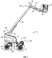
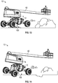
- a lift device e.g., an aerial work platform, a telehandler, a boom lift, a scissor lift, etc.
- lift device 10 includes a chassis, shown as lift base 12.
- the lift device 10 is another type of vehicle (e.g., a fire apparatus, a military vehicle, an airport rescue fire fighting ("ARFF") truck, a boom truck, a refuse vehicle, a fork lift, etc.).
- ARFF airport rescue fire fighting
- the lift base 12 supports a rotatable structure, shown as turntable 14, and a boom assembly, shown as boom 40.
- the turntable 14 is rotatable relative to the lift base 12.
- the turntable 14 includes a counterweight positioned at a rear of the turntable 14.
- the counterweight is otherwise positioned and/or at least a portion of the weight thereof is otherwise distributed throughout the lift device 10 (e.g., on the lift base 12, on a portion of the boom 40, etc.).
- a first end, shown as front end 20, of the lift base 12 is supported by a first plurality of tractive elements, shown as front tractive elements 16, and an opposing second end, shown as rear end 30, of the lift base 12 is supported by a second plurality of tractive elements, shown as rear tractive elements 18.
- the front tractive elements 16 and the rear tractive elements 18 include wheels.
- the front tractive elements 16 and/or the rear tractive elements 18 include a track element.
- the boom 40 includes a first boom section, shown as lower boom 50, and a second boom section, shown as upper boom 70.
- the boom 40 includes a different number and/or arrangement of boom sections (e.g., one, three, etc.).
- the boom 40 is an articulating boom assembly.
- the upper boom 70 is shorter in length than lower boom 50.
- the upper boom 70 is longer in length than the lower boom 50.
- the boom 40 is a telescopic, articulating boom assembly.
- the upper boom 70 and/or the lower boom 50 may include a plurality of telescoping boom sections that are configured to extend and retract along a longitudinal centerline thereof to selectively increase and decrease a length of the boom 40.
- the lower boom 50 has a first end (e.g., lower end, etc.), shown as base end 52, and an opposing second end, shown as intermediate end 54.
- the base end 52 of the lower boom 50 is pivotally coupled (e.g., pinned, etc.) to the turntable 14 at a joint, shown as lower boom pivot 56.
- the boom 40 includes a first actuator (e.g., pneumatic cylinder, electric actuator, hydraulic cylinder, etc.), shown as lower lift cylinder 60.
- the lower lift cylinder 60 has a first end coupled to the turntable 14 and an opposing second end coupled to the lower boom 50.
- the lower lift cylinder 60 is positioned to raise and lower the lower boom 50 relative to the turntable 14 about the lower boom pivot 56.
- the upper boom 70 has a first end, shown as intermediate end 72, and an opposing second end, shown as implement end 74.
- the intermediate end 72 of the upper boom 70 is pivotally coupled (e.g., pinned, etc.) to the intermediate end 54 of the lower boom 50 at a joint, shown as upper boom pivot 76.
- the boom 40 includes an implement, shown as platform assembly 92, coupled to the implement end 74 of the upper boom 70 with an extension arm, shown as jib arm 90.
- the jib arm 90 is configured to facilitate pivoting the platform assembly 92 about a lateral axis (e.g., pivot the platform assembly 92 up and down, etc.).
- the jib arm 90 is configured to facilitate pivoting the platform assembly 92 about a vertical axis (e.g., pivot the platform assembly 92 left and right, etc.). In some embodiments, the jib arm 90 is configured to facilitate extending and retracting the platform assembly 92 relative to the implement end 74 of the upper boom 70.
- the boom 40 includes a second actuator (e.g., pneumatic cylinder, electric actuator, hydraulic cylinder, etc.), shown as upper lift cylinder 80.
- the upper lift cylinder 80 is positioned to actuate (e.g., lift, rotate, elevate, etc.) the upper boom 70 and the platform assembly 92 relative to the lower boom 50 about the upper boom pivot 76.
- the platform assembly 92 is a structure that is particularly configured to support one or more workers.
- the platform assembly 92 includes an accessory or tool configured for use by a worker.
- Such tools may include pneumatic tools (e.g., impact wrench, airbrush, nail gun, ratchet, etc.), plasma cutters, welders, spotlights, etc.
- the platform assembly 92 includes a control panel to control operation of the lift device 10 (e.g., the turntable 14, the boom 40, etc.) from the platform assembly 92.
- the platform assembly 92 includes or is replaced with an accessory and/or tool (e.g., forklift forks, etc.).
- the lift device 10 includes a chassis leveling assembly, shown as leveling system 100.
- the leveling system 100 is configured to facilitate maintaining the lift base 12, the turntable 14, and/or the platform assembly 92 of the lift device 10 level relative to gravity (e.g., while stationary, while being driven on uneven and/or sloped ground, while operating the boom 40, etc.).
- the leveling system 100 includes a first leveling assembly, shown as front leveling assembly 110, pivotally coupled to the front end 20 of the lift base 12 and a second leveling assembly, shown as rear leveling assembly 120, pivotally coupled to the rear end 30 of the lift base 12.
- the front leveling assembly 110 and the rear leveling assembly 120 operate as a semi-independent suspension system for the lift device 10.
- a semi-independent suspension operation may facilitate providing two degrees of movement (e.g., pitch and roll, etc.) with each of the front leveling assembly 110 and the rear leveling assembly 120.
- the lift device 10 may provide various features and/or performance characteristics that are advantageous for lift device operation. Such advantages may include: (i) providing a platform capacity of up to 600 pounds or more, (ii) providing a platform height of up to 46.5 feet or more, (iii) providing a horizontal reach of up to 39 feet or more, (iv) providing a platform rotation of up to 180 degrees or more, (v) providing a boom swing of up to 360 degrees, (vi) providing a drive speed of up to 4.5 miles per hour or more, (vii) providing a gradeability of up to 45 degrees or more, (viii) providing a turning radius of 16 feet or less, (ix) providing a variable ground clearance between less than 6 inches to more than 22 inches, and/or (x) providing up to +/- 10 degrees or more of chassis pitch and roll, among still other advantages.
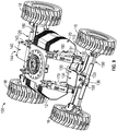
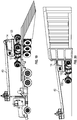
- the front leveling assembly 110 includes a first carrier arm, shown as front trailing arm 130; a first axle, shown as front axle 150; a first front actuator, shown as front right actuator 170; and a second front actuator, shown as front left actuator 180.
- the front right actuator 170 and the front left actuator 180 each include a hydraulic cylinder.
- the front right actuator 170 and/or the front left actuator 180 include another type of actuator (e.g., a pneumatic cylinder, an electric actuator, etc.).
- a pneumatic cylinder e.g., an electric actuator, etc.
- the front trailing arm 130 has a first portion, shown as base 131, positioned at a first end, shown as chassis end 132, of the front trailing arm 130.
- the front trailing arm 130 has a second portion, shown as projection 133, positioned at an opposing second end, shown as axle end 134, of the front trailing arm 130.
- the front trailing arm 130 has a third portion, shown as transition 135, extending between the base 131 and the projection 133. As shown in FIGS.
- the base 131 defines a pivot interface at the chassis end 132 of the front trailing arm 130 that pivotally couples to the front end 20 of the lift base 12 at a pair of pivot points positioned at a bottom end of the front end 20 of the lift base 12, shown as lower right pivot 26 and lower left pivot 28.
- a pivotal coupling between the front end 20 of the lift base 12 and the front trailing arm 130 may facilitate a pitch adjustment operation of the front leveling assembly 110 (e.g., pivoting of the front trailing arm 130 about a lateral axis extending through the lower right pivot 26 and the lower left pivot 28, etc.).
- the transition 135 extends from the base 131 to the projection 133 at an angle such that the projection 133 is elevated relative to the base 131.
- the front trailing arm 130 may thereby have a ramped or sloped profile (e.g., an elongated S-shape, an elongated Z-shape, etc.).
- the base 131 and the projection 133 are parallel with each other (e.g., planes defined by the base 131 and the projection 133 may be parallel, etc.). As shown in FIG.
- the front trailing arm 130 has a dual-plate construction such that the front trailing arm 130 includes a first, upper plate and a second, lower plate spaced from the first, upper plate (e.g., a space or gap is formed therebetween, etc.).
- the front trailing arm 130 has a single plate construction and/or has a solid structure.
- the front axle 150 has a first end, shown as right end 152, and an opposing second end, shown as left end 154.
- a first front tractive element 16 is coupled to the right end 152 of the front axle 150
- a second front tractive element 16 is coupled to the left end 154 of the front axle 150.
- the front axle 150 includes a coupler, shown as front axle pivot interface 156, positioned to engage a corresponding coupler, shown as front trailing arm pivot interface 136, defined by the projection 133 and positioned at the axle end 134 of the front trailing arm 130.
- FIG. 1 the front axle 150 includes a coupler, shown as front axle pivot interface 156, positioned to engage a corresponding coupler, shown as front trailing arm pivot interface 136, defined by the projection 133 and positioned at the axle end 134 of the front trailing arm 130.
- the front axle pivot interface 156 and the front trailing arm pivot interface 136 are configured to interengage and cooperatively receive a fastener, shown as pin 158.
- the pin 158 pivotally couples the front axle 150 to the axle end 134 of the front trailing arm 130.
- the pivotal joint between the front trailing arm 130 and the front axle 150 may facilitate a roll adjustment operation of the front leveling assembly 110 about the pin 158 (e.g., pivoting of the front axle 150 about a central longitudinal axis of the lift device 10, etc.).
- a first end (e.g., an upper end, etc.) of the front right actuator 170 is pivotally coupled to the front end 20 of the lift base 12 at a pivot point, shown as upper right pivot 22.
- an opposing second end (e.g., a lower end, etc.) of the front right actuator 170 is pivotally coupled to a corresponding pivot point positioned along the front axle 150 (e.g., proximate the right end 152 thereof, etc.).
- a first end (e.g., an upper end, etc.) of the front left actuator 180 is pivotally coupled to the front end 20 of the lift base 12 at a pivot point, shown as upper left pivot 24.
- an opposing second end (e.g., a lower end, etc.) of the front left actuator 180 is pivotally coupled to a corresponding pivot point positioned along the front axle 150 (e.g., proximate the left end 154 thereof, etc.).
- Such a pivotal coupling of (i) the front right actuator 170 between the front end 20 of the lift base 12 and the front axle 150 and (ii) the front left actuator 180 between the front end 20 of the lift base 12 and the front axle 150 may facilitate actively and/or passively providing the pitch and/or roll adjustment operations of the front leveling assembly 110 (e.g., pivoting of the front trailing arm 130 about a lateral axis extending through the lower right pivot 26 and the lower left pivot 28, pivoting of the front axle 150 about a central longitudinal axis of the lift device 10, etc.).
- the front leveling assembly 110 e.g., pivoting of the front trailing arm 130 about a lateral axis extending through the lower right pivot 26 and the lower left pivot 28, pivoting of the front axle 150 about a central longitudinal axis of the lift device 10, etc.
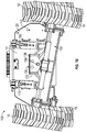
- the rear leveling assembly 120 includes a second carrier arm, shown as rear trailing arm 140; a second axle, shown as rear axle 160; a first rear actuator, shown as rear right actuator 190; and a second rear actuator, shown as rear left actuator 200.
- the rear right actuator 190 and the rear left actuator 200 each include a hydraulic cylinder.
- the rear right actuator 190 and/or the rear left actuator 200 include another type of actuator (e.g., a pneumatic cylinder, an electric actuator, etc.). As shown in FIGS.
- the rear trailing arm 140 has a first portion, shown as base 141, positioned at a first end, shown as chassis end 142, of the rear trailing arm 140. As shown in FIGS. 2-4 , 8 , and 9 , the rear trailing arm 140 has a second portion, shown as projection 143, positioned at an opposing second end, shown as axle end 144, of the rear trailing arm 140. As shown in FIGS. 2 and 3 , the rear trailing arm 140 has a third portion, shown as transition 145, extending between the base 141 and the projection 143.
- the base 141 defines a pivot interface at the chassis end 142 of the rear trailing arm 140 that pivotally couples to the rear end 30 of the lift base 12 at a pair of lower pivot points positioned at a bottom end of the rear end 30 of the lift base 12 (e.g., similar to the base 131 of the front trailing arm 130 at the lower right pivot 26 and the lower left pivot 28, etc.).
- a pivotal coupling between the rear end 30 of the lift base 12 and the rear trailing arm 140 may facilitate a pitch adjustment operation of the rear leveling assembly 120 (e.g., pivoting of the rear trailing arm 140 about a lateral axis extending through the pair of lower pivot points of the rear end 30 of the lift base 12, etc.).
- the transition 145 extends from the base 141 to the projection 143 at an angle such that the projection 143 is elevated relative to the base 141.
- the rear trailing arm 140 may thereby have a ramped or sloped profile (e.g., an elongated S-shape, an elongated Z-shape, etc.).
- the base 141 and the projection 143 are parallel with each other (e.g., planes defined by the base 141 and the projection 143 may be parallel, etc.).
- the rear trailing arm 140 has a dual-plate construction such that the rear trailing arm 140 includes a first, upper plate and a second, lower plate spaced from the first, upper plate (e.g., a space or gap is formed therebetween, etc.).
- the rear trailing arm 140 has a single plate construction and/or has a solid structure.
- the rear axle 160 has a first end, shown as right end 162, and an opposing second end, shown as left end 164.
- a first rear tractive element 18 is coupled to the right end 162 of the rear axle 160 and a second rear tractive element 18 is coupled to the left end 164 of the rear axle 160.
- the rear axle 160 includes a rear axle pivot interface (e.g., similar to the front axle pivot interface 156 of the front axle 150, etc.) positioned to engage a corresponding rear trailing arm pivot interface defined by the projection 143 and positioned at the axle end 144 of the rear trailing arm 140 (e.g., similar to the front trailing arm pivot interface 136 of the front trailing arm 130, etc.).
- the rear axle pivot interface and the rear trailing arm pivot interface are configured to interengage and cooperatively receive a fastener (e.g., similar to the pin 158, etc.) to pivotally couple the rear axle 160 to the rear trailing arm 140, according to an exemplary embodiment.
- the pivotal joint between the rear trailing arm 140 and the rear axle 160 may facilitate a roll adjustment operation of the rear leveling assembly 120 (e.g., pivoting of the rear axle 160 about a central longitudinal axis of the lift device 10, etc.).
- a first end (e.g., an upper end, etc.) of the rear right actuator 190 is pivotally coupled to the rear end 30 of the lift base 12 at a pivot point, shown as upper right pivot 32.
- an opposing second end (e.g., a lower end, etc.) of the rear right actuator 190 is pivotally coupled to a corresponding pivot point positioned along the rear axle 160 (e.g., proximate the right end 162 thereof, etc.).
- a first end (e.g., an upper end, etc.) of the rear left actuator 200 is pivotally coupled to the rear end 30 of the lift base 12 at a pivot point, shown as upper left pivot 34.
- an opposing second end (e.g., a lower end, etc.) of the rear left actuator 200 is pivotally coupled to a corresponding pivot point positioned along the rear axle 160 (e.g., proximate the left end 164 thereof, etc.).
- Such a pivotal coupling of (i) the rear right actuator 190 between the rear end 30 of the lift base 12 and the rear axle 160 and (ii) the rear left actuator 200 between the rear end 30 of the lift base 12 and the rear axle 160 may facilitate actively and/or passively providing the pitch and/or roll adjustment operations of the rear leveling assembly 120 (e.g., pivoting of the rear trailing arm 140 about a lateral axis extending through the pair of lower pivot points of the rear end 30 of the lift base 12, pivoting of the rear axle 160 about a central longitudinal axis of the lift device 10, etc.).
- the front axle 150 and the rear axle 160 include a drive system, shown as drive system 220.
- the drive system 220 includes actuators (e.g., pneumatic cylinders, electric actuators, hydraulic cylinders, etc.), shown as steering actuators 222, and drivers (e.g., electric actuators, motors, etc.), shown as drive actuators 224.
- the front axle 150 includes a pair of steering actuators 222. Each steering actuator 222 may be positioned to facilitate steering one of the front tractive elements 16 (e.g., independent steering of each of the front tractive elements 16, etc.).
- the rear axle 160 includes a pair of steering actuators 222.
- Each steering actuator 222 may be positioned to facilitate steering one of the rear tractive elements 18 (e.g., independent steering of each of the rear tractive elements 18, etc.).
- the front axle 150 and/or the rear axle 160 include a single steering actuator 222 positioned to facilitate steering both of the front tractive elements 16 and/or both of the rear tractive elements 18, respectively.
- the front axle 150 includes a pair of drive actuators 224.
- Each drive actuator 224 may be positioned to facilitate driving one of the front tractive elements 16.
- the rear axle 160 includes a pair of drive actuators 224.
- Each drive actuator 224 may be positioned to facilitate driving one of the rear tractive elements 18.
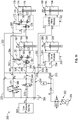
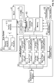
- the lift device 10 includes an actuator circuit, shown as actuator circuit 300, and a control system, shown as lift device control system 400.
- the actuator circuit 300 includes a hydraulic circuit configured to facilitate operating (e.g., driving the extension and/or retraction of, etc.) the front right actuator 170, the front left actuator 180, the rear right actuator 190, the rear left actuator 200, the steering actuators 222, and/or the drive actuators 224 (e.g., in embodiments where the actuators include hydraulic cylinders, etc.).
- the actuator circuit 300 includes an electric circuit (e.g., in embodiments where the actuators include electric actuators, etc.) and/or a pneumatic circuit (e.g., in embodiment where the actuators include pneumatic cylinders, etc.).
- the lift device control system 400 is configured to control the operation of the actuator circuit 300 and thereby the front right actuator 170, the front left actuator 180, the rear right actuator 190, the rear left actuator 200, the steering actuators 222, and/or the drive actuators 224 (e.g., the extension and/or retraction thereof, the relative motion between the front axle 150 and/or the rear axle 160 and the lift base 12, the pitch and/or roll adjustment operations of the front axle 150 and/or the rear axle 160, etc.).
- the actuator circuit 300 and thereby the front right actuator 170, the front left actuator 180, the rear right actuator 190, the rear left actuator 200, the steering actuators 222, and/or the drive actuators 224 (e.g., the extension and/or retraction thereof, the relative motion between the front axle 150 and/or the rear axle 160 and the lift base 12, the pitch and/or roll adjustment operations of the front axle 150 and/or the rear axle 160, etc.).
- the actuator circuit 300 includes a pump, shown as pump 302, a fluid reservoir, shown as tank 304, and a low pressure source, shown as low pressure source 306.
- the tank 304 is configured to supply the pump 302 with a fluid (e.g., hydraulic fluid, compressed air, etc.), which the pump 302 provides at a high pressure throughout the actuator circuit 300.
- the actuator circuit 300 includes a high pressure line, shown as high pressure line 310, that includes a first high pressure line, shown as front high pressure line 320, and a second high pressure line, shown as rear high pressure line 330.
- the front high pressure line 320 includes a first front high pressure line, shown as front right high pressure line 322, and a second front high pressure line, shown as front left high pressure line 324.
- the front right high pressure line 322 fluidly couples the pump 302 to a first front leveling module, shown as front right leveling module 172, associated with the front right actuator 170 and configured to facilitate an extension and retraction operation of the front right actuator 170.
- the front left high pressure line 324 fluidly couples the pump 302 to a second front leveling module, shown as front left leveling module 182, associated with the front left actuator 180 and configured to facilitate an extension and retraction operation of the front left actuator 180.
- the rear high pressure line 330 includes a first rear high pressure line, shown as rear right high pressure line 332, and a second rear high pressure line, shown as rear left high pressure line 334.
- the rear right high pressure line 332 fluidly couples the pump 302 to a first rear leveling module, shown as rear right leveling module 192, associated with the rear right actuator 190 and configured to facilitate an extension and retraction operation of the rear right actuator 190.
- the rear left high pressure line 334 fluidly couples the pump 302 to a second rear leveling module, shown as rear left leveling module 202, associated with the rear left actuator 200 and configured to facilitate an extension and retraction operation of the rear left actuator 200.
- the high pressure line 310 is positioned to facilitate providing high pressure fluid to a first chamber, shown as first chamber 174, first chamber 184, first chamber 194, and first chamber 204, of the front right actuator 170, the front left actuator 180, the rear right actuator 190, and the rear left actuator 200, respectively, to facilitate an extension operation thereof.
- the actuator circuit 300 includes a low pressure line including a first low pressure line, shown as front low pressure line 340, and a second low pressure line, shown as rear low pressure line 350.
- the front low pressure line 340 includes a first front low pressure line, shown as front right low pressure line 342, and a second front low pressure line, shown as front left low pressure line 344.
- the front right low pressure line 342 and the front left low pressure line 344 are fluidly coupled to a third low pressure line, shown as third low pressure line 346.
- the third low pressure line 346 fluidly couples the front right leveling module 172 and the front left leveling module 182 to a valve block, shown as valve block 370.
- the valve block 370 includes a valve, shown as valve 376, positioned to selectively fluidly couple the front low pressure line 340 to the low pressure source 306 and/or a reservoir, shown as tank 308 (e.g., based on a mode of operation of the lift device 10, etc.).
- the rear low pressure line 350 includes a first rear low pressure line, shown as rear right low pressure line 352, and a second rear low pressure line, shown as rear left low pressure line 354.
- the rear right low pressure line 352 and the rear left low pressure line 354 are fluidly coupled to a third low pressure line, shown as third low pressure line 356.
- the third low pressure line 356 fluidly couples the rear right leveling module 192 and the rear left leveling module 202 to the tank 308.
- the front low pressure line 340 is positioned to facilitate providing low pressure fluid to a second chamber, shown as second chamber 176 and second chamber 186, of the front right actuator 170 and the front left actuator 180, respectively, to facilitate a retraction operation thereof.
- rear low pressure line 350 is positioned to facilitate providing low pressure fluid to a second chamber, show as second chamber 196 and second chamber 206, of the rear right actuator 190 and the rear left actuator 200, respectively, to facilitate a retraction operation thereof.
- the actuator circuit 300 includes an auxiliary line, shown as auxiliary line 360.
- the auxiliary line 360 includes a first auxiliary line, shown as front right auxiliary line 362, and a second auxiliary line, shown as front left auxiliary line 364.
- the front right auxiliary line 362 and the front left auxiliary line 364 are fluidly coupled to a third auxiliary line, shown as third auxiliary line 366.
- the third auxiliary line 366 fluidly couples the front right leveling module 172 and the front left leveling module 182 to the valve block 370.
- the front low pressure line 340, the auxiliary line 360, and/or the valve block 370 are cooperatively engaged to operate the front right actuator 170 and the front left actuator 180 according to a passive mode of operation (e.g., based on the mode of operation of the lift device 10, a front leveling assembly free oscillation mode, etc.).
- a passive mode of operation e.g., based on the mode of operation of the lift device 10, a front leveling assembly free oscillation mode, etc.
- the passive mode of operation may be facilitated by activating (e.g., energizing, switching, opening, closing, etc.) valves (e.g., proportional valves, load holding valves, electro-magnetic valves, etc.) of the valve block 370, shown as valve 372 and valve 374.
- Such activation may include opening or closing one or more valves of the front right leveling module 172, shown as actuator valves 178, and the front left leveling module 182, shown as actuator valves 188.
- Such an operation may additionally or alternatively include activating (e.g., energizing, switching, opening, closing, etc.) a valve of the valve block 370, shown as valve 376, a valve of the front right leveling module 172, shown as actuator valve 179, and/or a valve of the front left leveling module 182, shown as actuator valve 189.
- Such activation may thereby fluidly couple the first chamber 174 and/or the second chamber 176 of the front right actuator 170 to the first chamber 184 and/or the second chamber 186 of the front left actuator 180 to facilitate a fluid flow (e.g., a free fluid flow, etc.) therebetween (e.g., between the first chamber 174 and the second chamber 186, between the second chamber 176 and the first chamber 184, etc.), as well as isolate the front right actuator 170 and the front left actuator 180 from the pump 302 (e.g., the front right actuator 170 and the front left actuator 180 do not receive high pressure fluid from the pump 302 such that they are not actively controlled, but passively controlled, etc.).
- the pressure from the low pressure source 306 is configured to ensure that the front low pressure line 340 remains pressurized (e.g., account for losses, etc.) through a valve, shown as check valve 378.
- the lift device control system 400 for the lift device 10 includes a controller 410.
- the controller 410 is configured to selectively engage, selectively disengage, control, and/or otherwise communicate with components of the lift device 10 (e.g., actively control the components thereof, etc.).
- the controller 410 is configured to facilitate passively controlling at least some of the components to the lift device 10 (e.g., based on the mode of operation of the lift device 10, the front leveling assembly 110, etc.). As shown in FIG.
- the controller 410 is coupled to the turntable 14, the boom 40, the leveling system 100 (e.g., the leveling modules thereof, etc.), the drive system 220 (e.g., the steering actuators 222, the drive actuators 224, etc.), the actuator circuit 300, various sensors including displacement sensors 402, roll sensors 404, pitch sensors 406, and load sensors 408, and a user interface 440.
- the controller 410 is coupled to more or fewer components.
- the controller 410 may be configured to actively control the pitch adjustment and/or the roll adjustment of at least the one of (i) the front leveling assembly 110 (e.g., through the extension and/or retraction of the front right actuator 170 and/or the front left actuator 180, etc.) and (ii) the rear leveling assembly 120 (e.g., through the extension and/or retraction of the rear right actuator 190 and/or the rear left actuator 200, etc.) to at least improve the orientation of the lift base 12, the turntable 14, and/or the boom 40 relative to gravity (e.g., while driving the lift device 10, while operating the boom 40, in a longitudinal direction, in lateral direction, etc.).
- the front leveling assembly 110 e.g., through the extension and/or retraction of the front right actuator 170 and/or the front left actuator 180, etc.
- the rear leveling assembly 120 e.g., through the extension and/or retraction of the rear right actuator 190 and/or the rear left actuator 200, etc.
- the controller 410 may maintain the lift base 12, the turntable 14 and/or the boom 40 level relative to gravity. Such control of the front leveling assembly 110 and/or the rear leveling assembly 120 may be based on a mode of operation of the lift device 10.
- the controller 410 may send and receive signals with the turntable 14, the boom 40, the leveling system 100, the drive system 220, the actuator circuit 300, the displacement sensors 402, the roll sensors 404, the pitch sensors 406, the load sensors 408, and/or the user interface 440.
- the controller 410 may be implemented as a general-purpose processor, an application specific integrated circuit (ASIC), one or more field programmable gate arrays (FPGAs), a digital-signal-processor (DSP), circuits containing one or more processing components, circuitry for supporting a microprocessor, a group of processing components, or other suitable electronic processing components.
- the controller 410 includes a processing circuit 412 and a memory 414.
- the processing circuit 412 may include an ASIC, one or more FPGAs, a DSP, circuits containing one or more processing components, circuitry for supporting a microprocessor, a group of processing components, or other suitable electronic processing components.
- the processing circuit 412 is configured to execute computer code stored in the memory 414 to facilitate the activities described herein.
- the memory 414 may be any volatile or non-volatile computer-readable storage medium capable of storing data or computer code relating to the activities described herein.
- the memory 414 includes computer code modules (e.g., executable code, object code, source code, script code, machine code, etc.) configured for execution by the processing circuit 412.
- the memory 414 includes various actuation profiles corresponding to loading conditions experienced by the leveling system 100 and/or corresponding to modes of operation of the lift device 10, according to an exemplary embodiment.
- controller 410 represents a collection of processing devices (e.g., servers, data centers, etc.). In such cases, the processing circuit 412 represents the collective processors of the devices, and the memory 414 represents the collective storage devices of the devices.
- the user interface 440 includes a display and an operator input.
- the display may be configured to display a graphical user interface, an image, an icon, and/or still other information.
- the display includes a graphical user interface configured to provide general information about the left device (e.g., vehicle speed, fuel level, warning lights, battery level, etc.).
- the graphical user interface may also be configured to display a current position of the leveling system 100, a current position of the boom 40, a current position of the turntable 14, an orientation of the lift base 12 (e.g., angle relative to a ground surface, etc.), and/or still other information relating to the lift device 10 and/or the leveling system 100.
- the operator input may be used by an operator to provide commands to at least one of the turntable 14, the boom 40, the leveling system 100, the drive system 220, and the actuator circuit 300.
- the operator input may include one or more buttons, knobs, touchscreens, switches, levers, joysticks, pedals, a steering wheel, or handles.
- the operator input may facilitate manual control of some or all aspects of the operation of the lift device 10. It should be understood that any type of display or input controls may be implemented with the systems and methods described herein.
- the controller 410 is configured to send and receive displacement data from the displacement sensors 402, roll data from the roll sensors 404, pitch data from the pitch sensors 406, and/or load data from the load sensors 408.
- the displacement sensors 402 may be positioned to acquire the displacement data regarding the front right actuator 170, the front left actuator 180, the rear right actuator 190, and/or the rear left actuator 200.
- the displacement data may be indicative of an amount of displacement and/or a position (e.g., extension, retraction, etc.) of the front right actuator 170, the front left actuator 180, the rear right actuator 190, and/or the rear left actuator 200 (e.g., relative to a neutral position, a nominal position, etc.).
- the roll sensors 404 may be positioned to acquire the roll data regarding the front leveling assembly 110, the rear leveling assembly 120, the front axle 150, and/or the rear axle 160.
- the roll data may be indicative of a roll angle and/or a rate of change of the roll angle of the front axle 150 about the pin 158 and/or the rear axle 160 about the corresponding pin thereof (e.g., relative to a horizontal roll alignment, a zero roll angle, etc.).
- the pitch sensors 406 may be positioned to acquire the pitch data regarding the front leveling assembly 110, the rear leveling assembly 120, the front axle 150, and/or the rear axle 160.
- the pitch data may be indicative of a pitch angle and/or a rate of change of the pitch angle of the front axle 150 about the coupling between the chassis end 132 of the front trailing arm 130 and the front end 20 of the lift base 12 and/or the rear axle 160 about the coupling between the chassis end 142 of the rear trailing arm 140 and the rear end 30 of the lift base 12 (e.g., relative to a horizontal pitch alignment, a zero pitch angle, etc.).
- the load sensors 408 may be positioned to acquire the load data regarding the front tractive elements 16 and/or the rear tractive elements 18.
- the load data may be indicative of a loading experienced by each of the front tractive elements 16 and/or each of the rear tractive elements 18.
- the controller 410 monitors the leveling status, the ground following status, and/or the height of the lift base 12 of the lift device 10 using the displacement data, the roll data, the pitch data, and/or the load data.
- the controller 410 is configured to facilitate operating the lift device in various modes of operation.
- the modes of operation of the lift device may include a transportation or stowed mode, a driving mode, a boom operation mode, and/or a calibration mode.
- the various modes of operation may be selected by an operator of the lift device 10 and/or automatically activated by the controller 410 based on the current operation of the lift device 10 (e.g., driving, operating the turntable 14, operating the boom 40, etc.).
- the controller 410 may actively control at least one of the front leveling assembly 110 and the rear leveling assembly 120 based on the mode of operation of the lift device 10.
- the controller 410 is configured to control operation of the front right actuator 170, the front left actuator 180, the rear right actuator 190, and/or the rear left actuator 200 based on at least one of the displacement data, the roll data, the pitch data, the load data, the mode of operation of the lift device 10, the operation of the turntable 14, and/or the operation of the boom 40.
- the controller 410 is configured to provide a command to the leveling system 100 (e.g., the leveling modules 172, 182, 192, and 202, etc.) to reduce the overall height of the lift base 12 to a target height (e.g., a minimum height, a stowed height, a shipping height, etc.) in response to the lift device 10 being switched into the transportation or stowed mode (e.g., to provide a squatting capability, etc.).
- a target height e.g., a minimum height, a stowed height, a shipping height, etc.
- Such a reduction in the overall height of the lift device 10 may facilitate storing the lift device within an ISO container (e.g., containerization, etc.) and/or provide greater stability and clearance during transportation (e.g., by lowering the center of gravity thereof, etc.).
- the controller 410 is configured to limit the speed of the lift device 10 and/or the operation of the turntable 14 and/or the boom 40 during the
- the controller 410 is configured to provide a command to the leveling system 100 to calibrate the displacement sensors 402, the roll sensors 404, the pitch sensors 406, and/or the load sensors 408 when the lift device 10 is in the calibration mode.
- the calibration mode may be activated each time the lift device 10 is turned on, on a periodic basis, in response to an operator command, and/or in response to the various data indicating potential miscalibration.
- the calibration mode may include the leveling system 100, the turntable 14, and/or the boom 40 returning to a nominal position (e.g., fully extended, fully retracted, etc.) such that the sensors may be zeroed out.
- the controller 410 is configured to actively control the rear leveling assembly 120 (e.g., based on the pitch data, the roll data, the displacement data, and/or the load data, etc.) and passively control the front leveling assembly 110 (e.g., as depicted in FIG. 11 , etc.) in response to the lift device 10 being operated in the driving mode.
- the front leveling assembly 110 is actively controlled, while the rear leveling assembly 120 is passively controlled when the lift device 10 is in the driving mode.
- the passive control of the front leveling assembly 110 may allow the front axle 150 to freely float and/or oscillate as the front tractive elements 16 encounter various terrain (e.g., slopes, pot holes, rocks, etc.) with the front right actuator 170 and the front left actuator 180 fluidly coupled (e.g., by the front low pressure line 340 and the auxiliary line 360, etc.).
- the front axle 150 is allowed to freely float in the roll direction.
- the front axle 150 is allowed to freely float in the roll direction and/or the pitch direction.
- the active control of the rear leveling assembly 120 e.g., the rear right actuator 190, the rear left actuator 200, etc.
- operation of the turntable 14 and/or the boom 40 are limited and/or disabled by the controller 410 during the driving mode.
- limiting the use of the turntable 14 and/or the boom 40 may maintain a lower center of gravity of the lift device 10 such that the lift device 10 may operate at higher speeds with improved stability.
- the controller 410 actively controlling of the rear leveling assembly 120 and passively controlling the front leveling assembly 110 provides a smooth ground following capability and increased terrainability (e.g., terrain negotiation, etc.).
- the actuator circuit 300 may also require less power (e.g., requires less hydraulic flow from the pump 302, since only the two rear actuators are actively controlled, compared to actively controlling all four actuators, etc.) during the driving mode of the lift device 10.
- the controller 410 is configured to actively control the front leveling assembly 110 and the rear leveling assembly 120 in response to the lift device 10 being operated in the boom operation mode (e.g., the turntable 14 and/or the boom 40 being operated, etc.).
- the active control of the rear leveling assembly 120 e.g., the rear right actuator 190, the rear left actuator 200, etc.
- the front leveling assembly 110 e.g., the front right actuator 170, the front left actuator 180, etc.
- the controller 410 limits the speed of the lift device 10 during the boom operation mode.
- operating the turntable 14 and/or the boom 40 may raise the center of gravity of the lift device 10 such that limiting the speed to lower operating speeds may facilitate increased stability.
- the controller 410 is configured to control operation of the front right actuator 170, the front left actuator 180, the rear right actuator 190, and the rear left actuator 200 based on at least one of the displacement data, the roll data, the pitch data, the load data, the position of the turntable 14, and/or the position of the boom 40 (e.g., the platform assembly 92, etc.) while the lift device 10 is in the boom operation mode.
- the boom operation mode may be used while the lift device 10 is stationary and/or moving (e.g., at a reduced speed, a governed speed, a creep speed, etc.).
- the various data may be used to maintain the lift base 12 level relative to gravity and/or maintain the front tractive elements 16 and the rear tractive elements 18 in contact with the ground as the center of gravity of the lift device 10 varies while in the boom operation mode (e.g., as the platform assembly 92 is selectively raised, lowered, extended, retracted, etc.).
- the lift device 10 is configured to operate (e.g., as controlled by the controller 410, etc.) in various modes (e.g., to negotiate various terrain or obstacles, facilitate transportation, etc.).
- the leveling system 100 of the lift device 10 is configured to increase the terrainability by increasing the capabilities of the lift device 10 to negotiate obstacles (e.g., pot holes, bumps, rocks, etc.), while maintaining the lift base 12, the turntable 14, and the boom 40 level relative to gravity (e.g., while operating in the driving mode, the boom operation mode, etc.).
- obstacles e.g., pot holes, bumps, rocks, etc.
- the leveling system 100 may additionally improve traction capabilities of the lift device 10 by distributing loads throughout the rear tractive elements 18 and/or the front tractive elements 16 while on and/or driving along uneven and/or sloped terrain.
- the leveling system 100 is configured to facilitate negotiation of and self-leveling on inclines or slopes, while maintaining the lift base 12, the turntable 14, and the boom 40 level relative to gravity (e.g., while operating in the driving mode, the boom operation mode, etc.).
- Such self-leveling may ease the loading of the lift device 10 onto a truck bed and/or increase the stability of the lift device 10 during operation of the boom 40 and/or the turntable 14 while on an incline or slope.
- the leveling system 100 is configured to facilitate a squatting capability such that the height of the lift base 12 is reduced.
- the squatting capability may provide greater stability and clearance while the lift device 10 is transported (e.g., via a truck, etc.) and/or facilitate containerization of the lift device 10 for shipping (e.g., by reducing the overall height of the lift device 10 such that the lift device 10 fits within an ISO container, etc.).
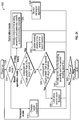
- the lift device 10 is powered on (e.g., in response to receiving a power on command from an operator, etc.).
- the controller 410 determines a mode of operation of the lift device 10 (e.g., transportation mode, calibration mode, driving mode, boom operation mode, etc.).
- the mode of operation may be manually operator selected, automatically initiated at power on, automatically initiated at power off, and/or automatically initiated in response to an operator input to drive the lift device 10, operate the turntable 14, and/or operate the boom 40.
- the controller 410 is configured to provide a command to the leveling system 100 to adjust the height of the lift base 12 to a target height (e.g., a transportation height, a stowed height, etc.) in response to the initiation of a transport mode of operation.
- the transport mode of operation may be initiated in response to an operator selection and/or in response to the lift device 10 being powered off.
- the controller 410 is configured to limit the speed of the lift device 10 and/or the operation of the turntable 14 and/or the boom 40 during the transportation mode of operation.
- the controller 410 is configured to provide a command to the leveling system 100 to run a sensor calibration algorithm to facilitate calibrating one or more sensors of the lift device 10 (e.g., the displacement sensors 402, the roll sensors 404, the pitch sensors 406, the load sensors 408, etc.) in response to the initiation of a calibration mode of operation.
- the calibration mode of operation may be initiated each time the lift device 10 is turned on, on a periodic basis, in response to an operator command, and/or in response to the various data indicating potential miscalibration.
- the sensor calibration algorithm may include the leveling system 100, the turntable 14, and/or the boom 40 returning to a nominal position (e.g., fully extended, fully retracted, etc.) such that the sensors may be zeroed out.
- the controller 410 is configured to actively control a first leveling assembly (e.g., the rear leveling assembly 120, etc.) and passively control a second leveling assembly (e.g., the front leveling assembly 110, etc.) of the leveling system 100 in response to initiation of the driving mode of operation.
- the driving mode may be initiated in response to an operator providing a command to drive the lift device 10 while the boom 40 is in a stowed position and/or a boom operation mode.
- the controller 410 is configured to control the first leveling assembly based on data (e.g., pitch data, roll data, the displacement data, the load data, etc.) received from the one or more sensors (e.g., the displacement sensors 402, the roll sensors 404, the pitch sensors 406, the load sensors 408, etc.).
- the controller 410 is configured to limit and/or disable operation of the turntable 14 and/or the boom 40 while the lift device 10 is in the driving mode.
- the controller 410 is configured to determine a compound tilt angle (e.g., a combination of the roll angle and the pitch angle, etc.) of the lift device 10 and compare the compound tilt angle to a first tilt angle threshold in response to the initiation of a boom operation mode.
- the boom operation mode may be initiated in response to an operator providing a command to operate the turntable 14 and/or the boom 40 of the lift device 10.
- the first tilt angle threshold is five degrees. In other embodiments, the first tilt angle threshold is less than or greater than five degrees (e.g., four degrees, six degrees, seven degrees, etc.).
- the controller 410 is configured to disable the leveling function, disable the drive function, and/or limit boom function (step 542). If the compound tilt angle is less than the first tilt angle threshold, the controller 410 is configured to compare the compound tilt angle to a second tilt angle threshold (step 544).
- the second tilt angle threshold is three degrees. In other embodiments, the second tilt angle threshold is less than or greater than three degrees (e.g., four degrees, two degrees, five degrees, etc.).
- the controller 410 is configured to limit drive function (e.g., to a creep speed, a reduced speed, etc.) and/or limit boom function (step 546). If the compound tilt angle is less than the second tilt angle threshold, the controller 410 is configured to provide a command to actively control the first leveling assembly (e.g., the rear leveling assembly 120, etc.) and the second leveling assembly (e.g., the front leveling assembly 110, etc.) of the leveling system 100 (step 548).
- first leveling assembly e.g., the rear leveling assembly 120, etc.
- the second leveling assembly e.g., the front leveling assembly 110, etc.
- the controller 410 is configured to control the first leveling assembly and the second leveling assembly based on (i) data (e.g., pitch data, roll data, load data, displacement data etc.) received from the one or more sensors (e.g., the displacement sensors 402, the roll sensors 404, the pitch sensors 406, the load sensors 408, etc.), (ii) the operation of the boom 40 (e.g., the position of the platform assembly 92 relative to the lift base 12, etc.), and/or (iii) the operation of the turntable 14 (e.g., rotation thereof, etc.).
- the controller 410 is configured to power off the lift device 10 (e.g., in response to receiving a power off command from an operator, etc.).
- the method 500 is concluded until a subsequent power on command is received (step 502).
- Coupled means the joining of two members directly or indirectly to one another. Such joining may be stationary (e.g., permanent) or moveable (e.g., removable, releasable, etc.). Such joining may be achieved with the two members or the two members and any additional intermediate members being integrally formed as a single unitary body with one another or with the two members or the two members and any additional intermediate members being attached to one another.
- the term "or” is used in its inclusive sense (and not in its exclusive sense) so that when used, for example, to connect a list of elements, the term “or” means one, some, or all of the elements in the list.
- Conjunctive language such as the phrase "at least one of X, Y, and Z," unless specifically stated otherwise, is otherwise understood with the context as used in general to convey that an item, term, etc. may be either X, Y, Z, X and Y, X and Z, Y and Z, or X, Y, and Z (i.e., any combination of X, Y, and Z).
- Conjunctive language is not generally intended to imply that certain embodiments require at least one of X, at least one of Y, and at least one of Z to each be present, unless otherwise indicated.
Landscapes
- Engineering & Computer Science (AREA)
- Structural Engineering (AREA)
- Mechanical Engineering (AREA)
- Life Sciences & Earth Sciences (AREA)
- Geology (AREA)
- Transportation (AREA)
- Civil Engineering (AREA)
- Architecture (AREA)
- Mining & Mineral Resources (AREA)
- General Engineering & Computer Science (AREA)
- Soil Working Implements (AREA)
- Operation Control Of Excavators (AREA)
- Forklifts And Lifting Vehicles (AREA)
- Vehicle Body Suspensions (AREA)
- Catching Or Destruction (AREA)
- Lifting Devices For Agricultural Implements (AREA)
Description
- Traditional boom lifts may include a chassis, a turntable coupled to the chassis, and a boom assembly. The boom assembly may include one or more boom sections that are pivotally connected. A lift cylinder elevates one of the boom sections relative to the turntable and/or another one of the boom sections, thereby elevating an implement (e.g., work platform, forks, etc.) that is coupled to the boom assembly.
-
US 2008/231011 A1 andUS 2008/231012 A1 each disclose a suspension system for a rigid beam tractor axle in which the axle is connected to the chassis by two orthogonally oriented pivot points and axle movement is controlled by double-acting hydraulic cylinders managed by a control system to improve the ride and handling characteristics of the tractor. -
GB 2 389 828 A - According to claim 1, one embodiment relates to a lift device. The lift device includes a chassis having a front end and a rear end, a boom pivotally coupled to the chassis, a rear leveling assembly, and a front leveling assembly. The rear leveling assembly includes a rear carrier arm, a rear axle, a first rear actuator, and a second rear actuator. The rear carrier arm is pivotally coupled to the rear end of the chassis to facilitate a rear pitch adjustment of the rear leveling assembly. The rear axle is pivotally coupled to the rear carrier arm to facilitate a rear roll adjustment of the rear leveling assembly. The rear axle has a first lateral end and an opposing second lateral end. The first rear actuator is pivotally coupled to the rear end of the chassis and the first lateral end of the rear axle. The second rear actuator is pivotally coupled to the rear end of the chassis and the opposing second lateral end of the rear axle. The first rear actuator and the second rear actuator facilitate providing active control of the rear pitch adjustment and the rear roll adjustment. The front leveling assembly includes a front carrier arm, a front axle, a first front actuator, and second front actuator. The front carrier arm is pivotally coupled to the front end of the chassis to facilitate a front pitch adjustment of the front leveling assembly. The front axle is pivotally coupled to the front carrier arm to facilitate a front roll adjustment of the front leveling assembly. The front axle has a first lateral end and an opposing second lateral end. The first front actuator is pivotally coupled to the front end of the chassis and the first lateral end of the front axle. The second front actuator is pivotally coupled to the front end of the chassis and the opposing second lateral end of the front axle. The first front actuator and the second front actuator are configured to be (i) selectively fluidly coupled to facilitate providing passive control of the front pitch adjustment and the front roll adjustment based on a mode of operation of the lift device and (ii) selectively fluidly decoupled to facilitate providing active control of the front pitch adjustment and the front roll adjustment based on the mode of operation of the lift device.
- According to claim 17, another embodiment relates to a leveling assembly for a lift device. The leveling assembly includes a first carrier arm, a first axle, a first actuator, and a second actuator. The first carrier arm includes a base, a projection, and a transition. The base defines a first interface configured to pivotally couple the carrier arm to a chassis of the lift device to facilitate a pitch adjustment of the leveling assembly. The projection defines a second interface. The transition extends between the base and the projection at an angle such that the projection is elevated relative to the base. The first axle defines a third interface positioned to engage with the second interface of the first carrier arm to pivotally couple the axle to the first carrier arm to facilitate a roll adjustment of the leveling assembly. The first axle has a first lateral end and an opposing second lateral end. The first actuator is pivotally coupled to the chassis and the first lateral end of the axle. The second actuator is pivotally coupled to the chassis and the opposing second lateral end of the axle. The levelling assembly also includes a second carrier arm, a second axle, a third actuator and a fourth actuator. The second carrier arm is pivotally coupled to an opposing side of the chassis. The second axle is pivotally coupled to the second carrier arm, the second axle having a first lateral end and an opposing second lateral end. The third actuator is pivotally coupled to the opposing side of the chassis and the first lateral end of the second axle. The fourth actuator is pivotally coupled to the opposing side of the chassis and the opposing second lateral end of the second axle. The first actuator and the second actuator are configured to be passively controlled during a first mode of operation of the lift device and the first actuator and the second actuator are configured to be actively controlled during a second mode of operation of the lift device. The first actuator and second actuator are (i) fluidly coupled to each other during the first mode of operation and (ii) fluidly decoupled from each other during the second mode of operation. The third actuator and the fourth actuator are configured to be actively controlled during the first mode of operation and the second mode of operation of the lift device.
- According to
claim 18, yet another embodiment relates to a vehicle. The vehicle includes a chassis having a first end and an opposing second end, a first leveling assembly pivotally coupled to the first end of the chassis, and a second leveling assembly pivotally coupled to the opposing second end of the chassis. The first leveling assembly is configured to be actively controlled to provide an active pitch adjustment and an active roll adjustment of the first leveling assembly during a first mode of operation and a second mode of operation. The second leveling assembly is configured to be passively controlled to provide a passive pitch adjustment and a passive roll adjustment of the second leveling assembly during the first mode of operation. The second leveling assembly is further configured to be actively controlled to provide an active pitch adjustment and an active roll adjustment of the second leveling assembly during the second mode of operation. - Another arrangement not forming part of the invention relates to a lift device. The lift device includes a chassis having a first end and an opposing second end, a boom pivotally coupled to the chassis, a first leveling assembly pivotally coupled to the first end of the chassis, a second leveling assembly pivotally coupled to the opposing second end of the chassis, and a control system. The first leveling assembly includes a first pair of actuators positioned to facilitate a first pitch adjustment and a first roll adjustment of the first end of the chassis. The second leveling assembly includes a second pair of actuators positioned to facilitate a second pitch adjustment and a second roll adjustment of the opposing second end of the chassis. The control system is configured to (i) actively control the first pair of actuators and the second pair of actuators during a first mode of operation of the lift device, and (ii) actively control the first pair of actuators and passively control the second pair of actuators during a second mode of operation of the lift device.
- Another arrangement not forming part of the invention relates to a method for controlling a leveling system of a lift device. The method includes providing a lift device including a chassis having a first end and an opposing second end, a first leveling assembly coupled to the first end of the chassis, and a second leveling assembly coupled to the opposing second end of the chassis. The first leveling assembly and the second leveling assembly are configured to facilitate a roll adjustment and a pitch adjustment of the first end and the opposing second end of the chassis, respectively. The lift device is operable in a first mode and a second mode. The method further includes actively controlling the first leveling assembly and the second leveling assembly during the first made, and actively controlling the first leveling assembly and passively controlling the second leveling assembly during the second mode such that the second leveling assembly freely floats.
- Another arrangement not forming part of the invention relates to a vehicle. The vehicle includes a chassis having a first end an opposing second end, a boom pivotally coupled to the chassis, a first leveling assembly pivotally coupled to the first end of the chassis, a second leveling assembly pivotally coupled to the opposing second end of the chassis, a sensor, and a control system. The first leveling assembly is configured to facilitate a first pitch adjustment and a first roll adjustment of the first end of the chassis. The second leveling assembly is configured to facilitate a second pitch adjustment and a second roll adjustment of the opposing second end of the chassis. The sensor is positioned to acquire operation
data regarding at least one of a roll angle of the chassis, a pitch angle of the chassis, a displacement of an actuator of the first leveling assembly, a displacement of an actuator of the second leveling assembly, a load on one or more tractive elements of the vehicle, and a position of the boom. The control system is configured to (i) actively control the first leveling assembly and the second leveling assembly to modulate the first pitch adjustment, the first roll adjustment, the second pitch adjustment, and the second roll adjustment based on the operation data during a boom operation mode to maintain the chassis level, (ii) actively control the first leveling assembly to modulate the first pitch adjustment and the first roll adjustment based on the operation data during a driving mode, and passively control the second leveling assembly during the driving mode such that the second leveling assembly freely floats. - The invention is capable of other embodiments and of being carried out in various ways. Alternative exemplary embodiments relate to other features and combinations of features as may be generally recited in the claims.
- The invention will become more fully understood from the following detailed description taken in conjunction with the accompanying drawings wherein like reference numerals refer to like elements, in which:
-
FIG. 1 is a perspective view of a lift device having a chassis, a leveling system, and a turntable, according to an exemplary embodiment; -
FIG. 2 is a detailed perspective view of the chassis and the turntable of the lift device ofFIG. 1 , according to an exemplary embodiment; -
FIGS. 3 and4 are detailed perspective views of the chassis and the leveling system of the lift device ofFIG. 1 , according to an exemplary embodiment; -
FIG. 5 is a side view of the chassis and the leveling system of the lift device ofFIG. 1 , according to an exemplary embodiment; -
FIG. 6 is a front view of the chassis and the leveling system of the lift device ofFIG. 1 , according to an exemplary embodiment; -
FIG. 7 is a perspective cross-sectional view of the leveling system and a steering system of the lift device ofFIG. 1 , according to an exemplary embodiment; -
FIGS. 8-10 are various views of the chassis and the leveling system of the lift device ofFIG. 1 in a pivoted orientation, according to an exemplary embodiment; -
FIG. 11 is a schematic diagram of an actuator circuit for the leveling system of the lift device ofFIG. 1 , according to an exemplary embodiment; -
FIG. 12 is a schematic block diagram of a control system of the lift device ofFIG. 1 , according to an exemplary embodiment; -
FIGS. 13-20 are illustrations of various modes of operation of the lift device ofFIG. 1 , according to various exemplary embodiments; and -
FIG. 21 is a flow diagram of a method for controlling a lift device according to various modes of operation, according to an exemplary embodiment. - Before turning to the figures, which illustrate the exemplary embodiments in detail, it should be understood that the present application is not limited to the details or methodology set forth in the description or illustrated in the figures. It should also be understood that the terminology is for the purpose of description only and should not be regarded as limiting.
- According to an exemplary embodiment, a lift device includes a leveling system configured to maintain a chassis of the lift device level relative to gravity (e.g., flat, horizontal, etc.) while stationary and/or while moving (e.g., being driven, etc.). According to an exemplary embodiment, the leveling system operates as a semi-independent suspension system for the lift device. The leveling system may include a front leveling assembly pivotally coupled to a front end of the chassis and a rear leveling assembly pivotally coupled to a rear end of the chassis. The terms "front," "rear," "left," and "right" as used herein are relative terms to provide reference and not necessarily intended to be limiting. According to an exemplary embodiment, the leveling system improves the traction capabilities of the lift device by distributing loads between the tractive elements of the lift device while on uneven and/or sloped terrain. The leveling system may facilitate operating the lift device on larger slopes more effectively than traditional lift devices. According to an exemplary embodiment, the front leveling assembly and the rear leveling assembly are configured to facilitate providing two degrees of movement (e.g., pitch and roll, etc.). The lift device is configured to operate in various modes of operation (e.g., a boom operation mode, a transport mode, a driving mode, a calibration mode, etc.), according to an exemplary embodiment. At least one of the front leveling assembly and the rear leveling assembly may be actively controlled by a controller based on the mode of operation of the lift device. By way of example, the rear leveling assembly may be actively controlled by the controller and the front leveling assembly may by passively operated during a first mode of operation (e.g., a driving mode, etc.) of the lift device. By way of another example, the front leveling assembly and the rear leveling assembly may both be actively controlled by the controller during a second mode of operation (e.g., a boom operation mode, etc.) of the lift device. "Active control" refers to engaging valves, pumps, etc. with a processing circuit or controller to selectively vary the extension, retraction, etc. of an actuator (e.g., a hydraulic cylinder, etc.). "Passive control" refers to actuator extension, retraction, etc. that is permitted but not regulated using a processing circuit or controller.
- According to the exemplary embodiment shown in
FIGS. 1-10 , a lift device (e.g., an aerial work platform, a telehandler, a boom lift, a scissor lift, etc.), shown aslift device 10, includes a chassis, shown aslift base 12. In other embodiments, thelift device 10 is another type of vehicle (e.g., a fire apparatus, a military vehicle, an airport rescue fire fighting ("ARFF") truck, a boom truck, a refuse vehicle, a fork lift, etc.). As shown inFIGS. 1 and2 , thelift base 12 supports a rotatable structure, shown asturntable 14, and a boom assembly, shown asboom 40. According to an exemplary embodiment, theturntable 14 is rotatable relative to thelift base 12. According to an exemplary embodiment, theturntable 14 includes a counterweight positioned at a rear of theturntable 14. In other embodiments, the counterweight is otherwise positioned and/or at least a portion of the weight thereof is otherwise distributed throughout the lift device 10 (e.g., on thelift base 12, on a portion of theboom 40, etc.). As shown inFIGS. 1-10 , a first end, shown asfront end 20, of thelift base 12 is supported by a first plurality of tractive elements, shown as fronttractive elements 16, and an opposing second end, shown asrear end 30, of thelift base 12 is supported by a second plurality of tractive elements, shown as reartractive elements 18. According to the exemplary embodiment shown inFIGS. 1-10 , the fronttractive elements 16 and the reartractive elements 18 include wheels. In other embodiments, the fronttractive elements 16 and/or the reartractive elements 18 include a track element. - As shown in
FIG. 1 , theboom 40 includes a first boom section, shown aslower boom 50, and a second boom section, shown asupper boom 70. In other embodiments, theboom 40 includes a different number and/or arrangement of boom sections (e.g., one, three, etc.). According to an exemplary embodiment, theboom 40 is an articulating boom assembly. In one embodiment, theupper boom 70 is shorter in length thanlower boom 50. In other embodiments, theupper boom 70 is longer in length than thelower boom 50. According to another exemplary embodiment, theboom 40 is a telescopic, articulating boom assembly. By way of example, theupper boom 70 and/or thelower boom 50 may include a plurality of telescoping boom sections that are configured to extend and retract along a longitudinal centerline thereof to selectively increase and decrease a length of theboom 40. - As shown in
FIG. 1 , thelower boom 50 has a first end (e.g., lower end, etc.), shown asbase end 52, and an opposing second end, shown asintermediate end 54. According to an exemplary embodiment, thebase end 52 of thelower boom 50 is pivotally coupled (e.g., pinned, etc.) to theturntable 14 at a joint, shown aslower boom pivot 56. As shown inFIG. 1 , theboom 40 includes a first actuator (e.g., pneumatic cylinder, electric actuator, hydraulic cylinder, etc.), shown aslower lift cylinder 60. Thelower lift cylinder 60 has a first end coupled to theturntable 14 and an opposing second end coupled to thelower boom 50. According to an exemplary embodiment, thelower lift cylinder 60 is positioned to raise and lower thelower boom 50 relative to theturntable 14 about thelower boom pivot 56. - As shown in
FIG. 1 , theupper boom 70 has a first end, shown asintermediate end 72, and an opposing second end, shown as implementend 74. According to an exemplary embodiment, theintermediate end 72 of theupper boom 70 is pivotally coupled (e.g., pinned, etc.) to theintermediate end 54 of thelower boom 50 at a joint, shown as upper boom pivot 76. As shown inFIG. 1 , theboom 40 includes an implement, shown asplatform assembly 92, coupled to the implementend 74 of theupper boom 70 with an extension arm, shown asjib arm 90. In some embodiments, thejib arm 90 is configured to facilitate pivoting theplatform assembly 92 about a lateral axis (e.g., pivot theplatform assembly 92 up and down, etc.). In some embodiments, thejib arm 90 is configured to facilitate pivoting theplatform assembly 92 about a vertical axis (e.g., pivot theplatform assembly 92 left and right, etc.). In some embodiments, thejib arm 90 is configured to facilitate extending and retracting theplatform assembly 92 relative to the implementend 74 of theupper boom 70. As shown inFIG. 1 , theboom 40 includes a second actuator (e.g., pneumatic cylinder, electric actuator, hydraulic cylinder, etc.), shown asupper lift cylinder 80. According to an exemplary embodiment, theupper lift cylinder 80 is positioned to actuate (e.g., lift, rotate, elevate, etc.) theupper boom 70 and theplatform assembly 92 relative to thelower boom 50 about the upper boom pivot 76. - According to an exemplary embodiment, the
platform assembly 92 is a structure that is particularly configured to support one or more workers. In some embodiments, theplatform assembly 92 includes an accessory or tool configured for use by a worker. Such tools may include pneumatic tools (e.g., impact wrench, airbrush, nail gun, ratchet, etc.), plasma cutters, welders, spotlights, etc. In some embodiments, theplatform assembly 92 includes a control panel to control operation of the lift device 10 (e.g., theturntable 14, theboom 40, etc.) from theplatform assembly 92. In other embodiments, theplatform assembly 92 includes or is replaced with an accessory and/or tool (e.g., forklift forks, etc.). - As shown in
FIGS. 1-10 , thelift device 10 includes a chassis leveling assembly, shown as levelingsystem 100. According to an exemplary embodiment, theleveling system 100 is configured to facilitate maintaining thelift base 12, theturntable 14, and/or theplatform assembly 92 of thelift device 10 level relative to gravity (e.g., while stationary, while being driven on uneven and/or sloped ground, while operating theboom 40, etc.). As shown inFIGS. 1-10 , theleveling system 100 includes a first leveling assembly, shown as front levelingassembly 110, pivotally coupled to thefront end 20 of thelift base 12 and a second leveling assembly, shown asrear leveling assembly 120, pivotally coupled to therear end 30 of thelift base 12. According to an exemplary embodiment, thefront leveling assembly 110 and therear leveling assembly 120 operate as a semi-independent suspension system for thelift device 10. Such a semi-independent suspension operation may facilitate providing two degrees of movement (e.g., pitch and roll, etc.) with each of thefront leveling assembly 110 and therear leveling assembly 120. - The
lift device 10 may provide various features and/or performance characteristics that are advantageous for lift device operation. Such advantages may include: (i) providing a platform capacity of up to 600 pounds or more, (ii) providing a platform height of up to 46.5 feet or more, (iii) providing a horizontal reach of up to 39 feet or more, (iv) providing a platform rotation of up to 180 degrees or more, (v) providing a boom swing of up to 360 degrees, (vi) providing a drive speed of up to 4.5 miles per hour or more, (vii) providing a gradeability of up to 45 degrees or more, (viii) providing a turning radius of 16 feet or less, (ix) providing a variable ground clearance between less than 6 inches to more than 22 inches, and/or (x) providing up to +/- 10 degrees or more of chassis pitch and roll, among still other advantages. - As shown in
FIGS. 2-10 , thefront leveling assembly 110 includes a first carrier arm, shown asfront trailing arm 130; a first axle, shown asfront axle 150; a first front actuator, shown as frontright actuator 170; and a second front actuator, shown as frontleft actuator 180. According to an exemplary embodiment, the frontright actuator 170 and the frontleft actuator 180 each include a hydraulic cylinder. In other embodiments, the frontright actuator 170 and/or the frontleft actuator 180 include another type of actuator (e.g., a pneumatic cylinder, an electric actuator, etc.). As shown inFIGS. 3 ,5 ,7 , and9 , thefront trailing arm 130 has a first portion, shown asbase 131, positioned at a first end, shown aschassis end 132, of the front trailingarm 130. As shown inFIGS. 2-4 and6-10 , thefront trailing arm 130 has a second portion, shown asprojection 133, positioned at an opposing second end, shown asaxle end 134, of the front trailingarm 130. As shown inFIGS. 3 ,4 , and7-9 , thefront trailing arm 130 has a third portion, shown astransition 135, extending between the base 131 and theprojection 133. As shown inFIGS. 3 ,5 , and7 , thebase 131 defines a pivot interface at thechassis end 132 of the front trailingarm 130 that pivotally couples to thefront end 20 of thelift base 12 at a pair of pivot points positioned at a bottom end of thefront end 20 of thelift base 12, shown as lowerright pivot 26 and lowerleft pivot 28. Such a pivotal coupling between thefront end 20 of thelift base 12 and the front trailingarm 130 may facilitate a pitch adjustment operation of the front leveling assembly 110 (e.g., pivoting of the front trailingarm 130 about a lateral axis extending through the lowerright pivot 26 and the lowerleft pivot 28, etc.). - According to the exemplary embodiment shown in
FIGS. 3 ,4 , and7-9 , thetransition 135 extends from the base 131 to theprojection 133 at an angle such that theprojection 133 is elevated relative to thebase 131. Thefront trailing arm 130 may thereby have a ramped or sloped profile (e.g., an elongated S-shape, an elongated Z-shape, etc.). In some embodiments, thebase 131 and theprojection 133 are parallel with each other (e.g., planes defined by thebase 131 and theprojection 133 may be parallel, etc.). As shown inFIG. 7 , thefront trailing arm 130 has a dual-plate construction such that the front trailingarm 130 includes a first, upper plate and a second, lower plate spaced from the first, upper plate (e.g., a space or gap is formed therebetween, etc.). In other embodiments, thefront trailing arm 130 has a single plate construction and/or has a solid structure. - As shown in
FIGS. 3-7 , thefront axle 150 has a first end, shown asright end 152, and an opposing second end, shown asleft end 154. A first fronttractive element 16 is coupled to theright end 152 of thefront axle 150, and a second fronttractive element 16 is coupled to theleft end 154 of thefront axle 150. As shown inFIG. 7 , thefront axle 150 includes a coupler, shown as frontaxle pivot interface 156, positioned to engage a corresponding coupler, shown as front trailingarm pivot interface 136, defined by theprojection 133 and positioned at theaxle end 134 of the front trailingarm 130. As shown inFIG. 7 , the frontaxle pivot interface 156 and the front trailingarm pivot interface 136 are configured to interengage and cooperatively receive a fastener, shown aspin 158. According to an exemplary embodiment, thepin 158 pivotally couples thefront axle 150 to theaxle end 134 of the front trailingarm 130. The pivotal joint between the front trailingarm 130 and thefront axle 150 may facilitate a roll adjustment operation of thefront leveling assembly 110 about the pin 158 (e.g., pivoting of thefront axle 150 about a central longitudinal axis of thelift device 10, etc.). - As shown in
FIGS. 2-4 and6 , a first end (e.g., an upper end, etc.) of the frontright actuator 170 is pivotally coupled to thefront end 20 of thelift base 12 at a pivot point, shown as upperright pivot 22. According to an exemplary embodiment, an opposing second end (e.g., a lower end, etc.) of the frontright actuator 170 is pivotally coupled to a corresponding pivot point positioned along the front axle 150 (e.g., proximate theright end 152 thereof, etc.). As shown inFIGS. 2-6 , a first end (e.g., an upper end, etc.) of the frontleft actuator 180 is pivotally coupled to thefront end 20 of thelift base 12 at a pivot point, shown as upperleft pivot 24. According to an exemplary embodiment, an opposing second end (e.g., a lower end, etc.) of the frontleft actuator 180 is pivotally coupled to a corresponding pivot point positioned along the front axle 150 (e.g., proximate theleft end 154 thereof, etc.). Such a pivotal coupling of (i) the frontright actuator 170 between thefront end 20 of thelift base 12 and thefront axle 150 and (ii) the frontleft actuator 180 between thefront end 20 of thelift base 12 and thefront axle 150 may facilitate actively and/or passively providing the pitch and/or roll adjustment operations of the front leveling assembly 110 (e.g., pivoting of the front trailingarm 130 about a lateral axis extending through the lowerright pivot 26 and the lowerleft pivot 28, pivoting of thefront axle 150 about a central longitudinal axis of thelift device 10, etc.). - As shown in
FIGS. 2-5 ,8 , and9 , therear leveling assembly 120 includes a second carrier arm, shown as rear trailingarm 140; a second axle, shown asrear axle 160; a first rear actuator, shown as rearright actuator 190; and a second rear actuator, shown as rearleft actuator 200. According to an exemplary embodiment, the rearright actuator 190 and the rearleft actuator 200 each include a hydraulic cylinder. In other embodiments, the rearright actuator 190 and/or the rearleft actuator 200 include another type of actuator (e.g., a pneumatic cylinder, an electric actuator, etc.). As shown inFIGS. 2 ,3 , and5 , therear trailing arm 140 has a first portion, shown asbase 141, positioned at a first end, shown aschassis end 142, of therear trailing arm 140. As shown inFIGS. 2-4 ,8 , and9 , therear trailing arm 140 has a second portion, shown asprojection 143, positioned at an opposing second end, shown asaxle end 144, of therear trailing arm 140. As shown inFIGS. 2 and3 , therear trailing arm 140 has a third portion, shown astransition 145, extending between the base 141 and theprojection 143. According to an exemplary embodiment, thebase 141 defines a pivot interface at thechassis end 142 of therear trailing arm 140 that pivotally couples to therear end 30 of thelift base 12 at a pair of lower pivot points positioned at a bottom end of therear end 30 of the lift base 12 (e.g., similar to thebase 131 of the front trailingarm 130 at the lowerright pivot 26 and the lowerleft pivot 28, etc.). Such a pivotal coupling between therear end 30 of thelift base 12 and therear trailing arm 140 may facilitate a pitch adjustment operation of the rear leveling assembly 120 (e.g., pivoting of therear trailing arm 140 about a lateral axis extending through the pair of lower pivot points of therear end 30 of thelift base 12, etc.). - According to the exemplary embodiment shown in
FIGS. 2 and3 , thetransition 145 extends from the base 141 to theprojection 143 at an angle such that theprojection 143 is elevated relative to thebase 141. Therear trailing arm 140 may thereby have a ramped or sloped profile (e.g., an elongated S-shape, an elongated Z-shape, etc.). In some embodiments, thebase 141 and theprojection 143 are parallel with each other (e.g., planes defined by thebase 141 and theprojection 143 may be parallel, etc.). According to an exemplary embodiment, therear trailing arm 140 has a dual-plate construction such that therear trailing arm 140 includes a first, upper plate and a second, lower plate spaced from the first, upper plate (e.g., a space or gap is formed therebetween, etc.). In other embodiments, therear trailing arm 140 has a single plate construction and/or has a solid structure. - As shown in
FIGS. 3-5 , therear axle 160 has a first end, shown asright end 162, and an opposing second end, shown asleft end 164. A first reartractive element 18 is coupled to theright end 162 of therear axle 160 and a second reartractive element 18 is coupled to theleft end 164 of therear axle 160. According to an exemplary embodiment, therear axle 160 includes a rear axle pivot interface (e.g., similar to the frontaxle pivot interface 156 of thefront axle 150, etc.) positioned to engage a corresponding rear trailing arm pivot interface defined by theprojection 143 and positioned at theaxle end 144 of the rear trailing arm 140 (e.g., similar to the front trailingarm pivot interface 136 of the front trailingarm 130, etc.). The rear axle pivot interface and the rear trailing arm pivot interface are configured to interengage and cooperatively receive a fastener (e.g., similar to thepin 158, etc.) to pivotally couple therear axle 160 to therear trailing arm 140, according to an exemplary embodiment. The pivotal joint between the rear trailingarm 140 and therear axle 160 may facilitate a roll adjustment operation of the rear leveling assembly 120 (e.g., pivoting of therear axle 160 about a central longitudinal axis of thelift device 10, etc.). - As shown in
FIGS. 2 and3 , a first end (e.g., an upper end, etc.) of the rearright actuator 190 is pivotally coupled to therear end 30 of thelift base 12 at a pivot point, shown as upperright pivot 32. According to an exemplary embodiment, an opposing second end (e.g., a lower end, etc.) of the rearright actuator 190 is pivotally coupled to a corresponding pivot point positioned along the rear axle 160 (e.g., proximate theright end 162 thereof, etc.). As shown inFIGS. 3-5 , a first end (e.g., an upper end, etc.) of the rearleft actuator 200 is pivotally coupled to therear end 30 of thelift base 12 at a pivot point, shown as upperleft pivot 34. According to an exemplary embodiment, an opposing second end (e.g., a lower end, etc.) of the rearleft actuator 200 is pivotally coupled to a corresponding pivot point positioned along the rear axle 160 (e.g., proximate theleft end 164 thereof, etc.). Such a pivotal coupling of (i) the rearright actuator 190 between therear end 30 of thelift base 12 and therear axle 160 and (ii) the rearleft actuator 200 between therear end 30 of thelift base 12 and therear axle 160 may facilitate actively and/or passively providing the pitch and/or roll adjustment operations of the rear leveling assembly 120 (e.g., pivoting of therear trailing arm 140 about a lateral axis extending through the pair of lower pivot points of therear end 30 of thelift base 12, pivoting of therear axle 160 about a central longitudinal axis of thelift device 10, etc.). - As shown in
FIGS. 3 ,4 ,6 , and7 , thefront axle 150 and therear axle 160 include a drive system, shown asdrive system 220. Thedrive system 220 includes actuators (e.g., pneumatic cylinders, electric actuators, hydraulic cylinders, etc.), shown assteering actuators 222, and drivers (e.g., electric actuators, motors, etc.), shown asdrive actuators 224. As shown inFIGS. 3 ,4 , and6 , thefront axle 150 includes a pair ofsteering actuators 222. Eachsteering actuator 222 may be positioned to facilitate steering one of the front tractive elements 16 (e.g., independent steering of each of the fronttractive elements 16, etc.). According to an exemplary embodiment, therear axle 160 includes a pair ofsteering actuators 222. Eachsteering actuator 222 may be positioned to facilitate steering one of the rear tractive elements 18 (e.g., independent steering of each of the reartractive elements 18, etc.). In other embodiments, thefront axle 150 and/or therear axle 160 include asingle steering actuator 222 positioned to facilitate steering both of the fronttractive elements 16 and/or both of the reartractive elements 18, respectively. As shown inFIGS. 3 ,4 , and7 , thefront axle 150 includes a pair ofdrive actuators 224. Eachdrive actuator 224 may be positioned to facilitate driving one of the fronttractive elements 16. According to an exemplary embodiment, therear axle 160 includes a pair ofdrive actuators 224. Eachdrive actuator 224 may be positioned to facilitate driving one of the reartractive elements 18. - As shown in
FIGS. 1 and2 , thelift device 10 includes an actuator circuit, shown asactuator circuit 300, and a control system, shown as liftdevice control system 400. According to an exemplary embodiment, theactuator circuit 300 includes a hydraulic circuit configured to facilitate operating (e.g., driving the extension and/or retraction of, etc.) the frontright actuator 170, the frontleft actuator 180, the rearright actuator 190, the rearleft actuator 200, thesteering actuators 222, and/or the drive actuators 224 (e.g., in embodiments where the actuators include hydraulic cylinders, etc.). In other embodiments, theactuator circuit 300 includes an electric circuit (e.g., in embodiments where the actuators include electric actuators, etc.) and/or a pneumatic circuit (e.g., in embodiment where the actuators include pneumatic cylinders, etc.). According to an exemplary embodiment, the liftdevice control system 400 is configured to control the operation of theactuator circuit 300 and thereby the frontright actuator 170, the frontleft actuator 180, the rearright actuator 190, the rearleft actuator 200, thesteering actuators 222, and/or the drive actuators 224 (e.g., the extension and/or retraction thereof, the relative motion between thefront axle 150 and/or therear axle 160 and thelift base 12, the pitch and/or roll adjustment operations of thefront axle 150 and/or therear axle 160, etc.). - According to the exemplary embodiment shown in
FIG. 11 , theactuator circuit 300 includes a pump, shown aspump 302, a fluid reservoir, shown astank 304, and a low pressure source, shown aslow pressure source 306. Thetank 304 is configured to supply thepump 302 with a fluid (e.g., hydraulic fluid, compressed air, etc.), which thepump 302 provides at a high pressure throughout theactuator circuit 300. As shown inFIG. 11 , theactuator circuit 300 includes a high pressure line, shown ashigh pressure line 310, that includes a first high pressure line, shown as fronthigh pressure line 320, and a second high pressure line, shown as rearhigh pressure line 330. The fronthigh pressure line 320 includes a first front high pressure line, shown as front righthigh pressure line 322, and a second front high pressure line, shown as front lefthigh pressure line 324. As shown inFIG. 11 , the front righthigh pressure line 322 fluidly couples thepump 302 to a first front leveling module, shown as frontright leveling module 172, associated with the frontright actuator 170 and configured to facilitate an extension and retraction operation of the frontright actuator 170. The front lefthigh pressure line 324 fluidly couples thepump 302 to a second front leveling module, shown as frontleft leveling module 182, associated with the frontleft actuator 180 and configured to facilitate an extension and retraction operation of the frontleft actuator 180. - As shown in
FIG. 11 , the rearhigh pressure line 330 includes a first rear high pressure line, shown as rear righthigh pressure line 332, and a second rear high pressure line, shown as rear lefthigh pressure line 334. The rear righthigh pressure line 332 fluidly couples thepump 302 to a first rear leveling module, shown as rearright leveling module 192, associated with the rearright actuator 190 and configured to facilitate an extension and retraction operation of the rearright actuator 190. The rear lefthigh pressure line 334 fluidly couples thepump 302 to a second rear leveling module, shown as rearleft leveling module 202, associated with the rearleft actuator 200 and configured to facilitate an extension and retraction operation of the rearleft actuator 200. According to an exemplary embodiment, thehigh pressure line 310 is positioned to facilitate providing high pressure fluid to a first chamber, shown asfirst chamber 174,first chamber 184,first chamber 194, andfirst chamber 204, of the frontright actuator 170, the frontleft actuator 180, the rearright actuator 190, and the rearleft actuator 200, respectively, to facilitate an extension operation thereof. - As shown in
FIG. 11 , theactuator circuit 300 includes a low pressure line including a first low pressure line, shown as front low pressure line 340, and a second low pressure line, shown as rearlow pressure line 350. The front low pressure line 340 includes a first front low pressure line, shown as front rightlow pressure line 342, and a second front low pressure line, shown as front leftlow pressure line 344. As shown inFIG. 11 , the front rightlow pressure line 342 and the front leftlow pressure line 344 are fluidly coupled to a third low pressure line, shown as thirdlow pressure line 346. The thirdlow pressure line 346 fluidly couples the frontright leveling module 172 and the frontleft leveling module 182 to a valve block, shown asvalve block 370. Thevalve block 370 includes a valve, shown as valve 376, positioned to selectively fluidly couple the front low pressure line 340 to thelow pressure source 306 and/or a reservoir, shown as tank 308 (e.g., based on a mode of operation of thelift device 10, etc.). - As shown in
FIG. 11 , the rearlow pressure line 350 includes a first rear low pressure line, shown as rear rightlow pressure line 352, and a second rear low pressure line, shown as rear leftlow pressure line 354. As shown inFIG. 11 , the rear rightlow pressure line 352 and the rear leftlow pressure line 354 are fluidly coupled to a third low pressure line, shown as thirdlow pressure line 356. The thirdlow pressure line 356 fluidly couples the rearright leveling module 192 and the rearleft leveling module 202 to thetank 308. According to an exemplary embodiment, the front low pressure line 340 is positioned to facilitate providing low pressure fluid to a second chamber, shown assecond chamber 176 andsecond chamber 186, of the frontright actuator 170 and the frontleft actuator 180, respectively, to facilitate a retraction operation thereof. According to an exemplary embodiment, rearlow pressure line 350 is positioned to facilitate providing low pressure fluid to a second chamber, show assecond chamber 196 andsecond chamber 206, of the rearright actuator 190 and the rearleft actuator 200, respectively, to facilitate a retraction operation thereof. - As shown in
FIG. 11 , theactuator circuit 300 includes an auxiliary line, shown asauxiliary line 360. Theauxiliary line 360 includes a first auxiliary line, shown as front rightauxiliary line 362, and a second auxiliary line, shown as front leftauxiliary line 364. The front rightauxiliary line 362 and the front leftauxiliary line 364 are fluidly coupled to a third auxiliary line, shown as thirdauxiliary line 366. The thirdauxiliary line 366 fluidly couples the frontright leveling module 172 and the frontleft leveling module 182 to thevalve block 370. According to an exemplary embodiment, the front low pressure line 340, theauxiliary line 360, and/or thevalve block 370 are cooperatively engaged to operate the frontright actuator 170 and the frontleft actuator 180 according to a passive mode of operation (e.g., based on the mode of operation of thelift device 10, a front leveling assembly free oscillation mode, etc.). By way of example, the passive mode of operation may be facilitated by activating (e.g., energizing, switching, opening, closing, etc.) valves (e.g., proportional valves, load holding valves, electro-magnetic valves, etc.) of thevalve block 370, shown as valve 372 andvalve 374. Such activation may include opening or closing one or more valves of the frontright leveling module 172, shown asactuator valves 178, and the frontleft leveling module 182, shown asactuator valves 188. Such an operation may additionally or alternatively include activating (e.g., energizing, switching, opening, closing, etc.) a valve of thevalve block 370, shown as valve 376, a valve of the frontright leveling module 172, shown asactuator valve 179, and/or a valve of the frontleft leveling module 182, shown asactuator valve 189. Such activation may thereby fluidly couple thefirst chamber 174 and/or thesecond chamber 176 of the frontright actuator 170 to thefirst chamber 184 and/or thesecond chamber 186 of the frontleft actuator 180 to facilitate a fluid flow (e.g., a free fluid flow, etc.) therebetween (e.g., between thefirst chamber 174 and thesecond chamber 186, between thesecond chamber 176 and thefirst chamber 184, etc.), as well as isolate the frontright actuator 170 and the frontleft actuator 180 from the pump 302 (e.g., the frontright actuator 170 and the frontleft actuator 180 do not receive high pressure fluid from thepump 302 such that they are not actively controlled, but passively controlled, etc.). According to an exemplary embodiment, the pressure from thelow pressure source 306 is configured to ensure that the front low pressure line 340 remains pressurized (e.g., account for losses, etc.) through a valve, shown ascheck valve 378. - According to the exemplary embodiment shown in
FIG. 12 , the liftdevice control system 400 for thelift device 10 includes acontroller 410. In one embodiment, thecontroller 410 is configured to selectively engage, selectively disengage, control, and/or otherwise communicate with components of the lift device 10 (e.g., actively control the components thereof, etc.). In some embodiments, thecontroller 410 is configured to facilitate passively controlling at least some of the components to the lift device 10 (e.g., based on the mode of operation of thelift device 10, thefront leveling assembly 110, etc.). As shown inFIG. 12 , thecontroller 410 is coupled to theturntable 14, theboom 40, the leveling system 100 (e.g., the leveling modules thereof, etc.), the drive system 220 (e.g., thesteering actuators 222, thedrive actuators 224, etc.), theactuator circuit 300, various sensors includingdisplacement sensors 402, rollsensors 404,pitch sensors 406, andload sensors 408, and auser interface 440. In other embodiments, thecontroller 410 is coupled to more or fewer components. Thecontroller 410 may be configured to actively control the pitch adjustment and/or the roll adjustment of at least the one of (i) the front leveling assembly 110 (e.g., through the extension and/or retraction of the frontright actuator 170 and/or the frontleft actuator 180, etc.) and (ii) the rear leveling assembly 120 (e.g., through the extension and/or retraction of the rearright actuator 190 and/or the rearleft actuator 200, etc.) to at least improve the orientation of thelift base 12, theturntable 14, and/or theboom 40 relative to gravity (e.g., while driving thelift device 10, while operating theboom 40, in a longitudinal direction, in lateral direction, etc.). By way of example, thecontroller 410 may maintain thelift base 12, theturntable 14 and/or theboom 40 level relative to gravity. Such control of thefront leveling assembly 110 and/or therear leveling assembly 120 may be based on a mode of operation of thelift device 10. By way of example, thecontroller 410 may send and receive signals with theturntable 14, theboom 40, theleveling system 100, thedrive system 220, theactuator circuit 300, thedisplacement sensors 402, theroll sensors 404, thepitch sensors 406, theload sensors 408, and/or theuser interface 440. - The
controller 410 may be implemented as a general-purpose processor, an application specific integrated circuit (ASIC), one or more field programmable gate arrays (FPGAs), a digital-signal-processor (DSP), circuits containing one or more processing components, circuitry for supporting a microprocessor, a group of processing components, or other suitable electronic processing components. According to the exemplary embodiment shown inFIG. 4 , thecontroller 410 includes aprocessing circuit 412 and amemory 414. Theprocessing circuit 412 may include an ASIC, one or more FPGAs, a DSP, circuits containing one or more processing components, circuitry for supporting a microprocessor, a group of processing components, or other suitable electronic processing components. In some embodiments, theprocessing circuit 412 is configured to execute computer code stored in thememory 414 to facilitate the activities described herein. Thememory 414 may be any volatile or non-volatile computer-readable storage medium capable of storing data or computer code relating to the activities described herein. According to an exemplary embodiment, thememory 414 includes computer code modules (e.g., executable code, object code, source code, script code, machine code, etc.) configured for execution by theprocessing circuit 412. Thememory 414 includes various actuation profiles corresponding to loading conditions experienced by theleveling system 100 and/or corresponding to modes of operation of thelift device 10, according to an exemplary embodiment. In some embodiments,controller 410 represents a collection of processing devices (e.g., servers, data centers, etc.). In such cases, theprocessing circuit 412 represents the collective processors of the devices, and thememory 414 represents the collective storage devices of the devices. - In one embodiment, the
user interface 440 includes a display and an operator input. The display may be configured to display a graphical user interface, an image, an icon, and/or still other information. In one embodiment, the display includes a graphical user interface configured to provide general information about the left device (e.g., vehicle speed, fuel level, warning lights, battery level, etc.). The graphical user interface may also be configured to display a current position of theleveling system 100, a current position of theboom 40, a current position of theturntable 14, an orientation of the lift base 12 (e.g., angle relative to a ground surface, etc.), and/or still other information relating to thelift device 10 and/or theleveling system 100. - The operator input may be used by an operator to provide commands to at least one of the
turntable 14, theboom 40, theleveling system 100, thedrive system 220, and theactuator circuit 300. The operator input may include one or more buttons, knobs, touchscreens, switches, levers, joysticks, pedals, a steering wheel, or handles. The operator input may facilitate manual control of some or all aspects of the operation of thelift device 10. It should be understood that any type of display or input controls may be implemented with the systems and methods described herein. - According to an exemplary embodiment, the
controller 410 is configured to send and receive displacement data from thedisplacement sensors 402, roll data from theroll sensors 404, pitch data from thepitch sensors 406, and/or load data from theload sensors 408. Thedisplacement sensors 402 may be positioned to acquire the displacement data regarding the frontright actuator 170, the frontleft actuator 180, the rearright actuator 190, and/or the rearleft actuator 200. The displacement data may be indicative of an amount of displacement and/or a position (e.g., extension, retraction, etc.) of the frontright actuator 170, the frontleft actuator 180, the rearright actuator 190, and/or the rear left actuator 200 (e.g., relative to a neutral position, a nominal position, etc.). Theroll sensors 404 may be positioned to acquire the roll data regarding thefront leveling assembly 110, therear leveling assembly 120, thefront axle 150, and/or therear axle 160. The roll data may be indicative of a roll angle and/or a rate of change of the roll angle of thefront axle 150 about thepin 158 and/or therear axle 160 about the corresponding pin thereof (e.g., relative to a horizontal roll alignment, a zero roll angle, etc.). Thepitch sensors 406 may be positioned to acquire the pitch data regarding thefront leveling assembly 110, therear leveling assembly 120, thefront axle 150, and/or therear axle 160. The pitch data may be indicative of a pitch angle and/or a rate of change of the pitch angle of thefront axle 150 about the coupling between thechassis end 132 of the front trailingarm 130 and thefront end 20 of thelift base 12 and/or therear axle 160 about the coupling between thechassis end 142 of therear trailing arm 140 and therear end 30 of the lift base 12 (e.g., relative to a horizontal pitch alignment, a zero pitch angle, etc.). Theload sensors 408 may be positioned to acquire the load data regarding the fronttractive elements 16 and/or the reartractive elements 18. The load data may be indicative of a loading experienced by each of the fronttractive elements 16 and/or each of the reartractive elements 18. According to an exemplary embodiment, thecontroller 410 monitors the leveling status, the ground following status, and/or the height of thelift base 12 of thelift device 10 using the displacement data, the roll data, the pitch data, and/or the load data. - According to an exemplary embodiment, the
controller 410 is configured to facilitate operating the lift device in various modes of operation. The modes of operation of the lift device may include a transportation or stowed mode, a driving mode, a boom operation mode, and/or a calibration mode. The various modes of operation may be selected by an operator of thelift device 10 and/or automatically activated by thecontroller 410 based on the current operation of the lift device 10 (e.g., driving, operating theturntable 14, operating theboom 40, etc.). Thecontroller 410 may actively control at least one of thefront leveling assembly 110 and therear leveling assembly 120 based on the mode of operation of thelift device 10. According to an exemplary embodiment, thecontroller 410 is configured to control operation of the frontright actuator 170, the frontleft actuator 180, the rearright actuator 190, and/or the rearleft actuator 200 based on at least one of the displacement data, the roll data, the pitch data, the load data, the mode of operation of thelift device 10, the operation of theturntable 14, and/or the operation of theboom 40. - According to an exemplary embodiment, the
controller 410 is configured to provide a command to the leveling system 100 (e.g., the levelingmodules lift base 12 to a target height (e.g., a minimum height, a stowed height, a shipping height, etc.) in response to thelift device 10 being switched into the transportation or stowed mode (e.g., to provide a squatting capability, etc.). Such a reduction in the overall height of thelift device 10 may facilitate storing the lift device within an ISO container (e.g., containerization, etc.) and/or provide greater stability and clearance during transportation (e.g., by lowering the center of gravity thereof, etc.). In some embodiments, thecontroller 410 is configured to limit the speed of thelift device 10 and/or the operation of theturntable 14 and/or theboom 40 during the transportation mode. - According to an exemplary embodiment, the
controller 410 is configured to provide a command to theleveling system 100 to calibrate thedisplacement sensors 402, theroll sensors 404, thepitch sensors 406, and/or theload sensors 408 when thelift device 10 is in the calibration mode. The calibration mode may be activated each time thelift device 10 is turned on, on a periodic basis, in response to an operator command, and/or in response to the various data indicating potential miscalibration. The calibration mode may include theleveling system 100, theturntable 14, and/or theboom 40 returning to a nominal position (e.g., fully extended, fully retracted, etc.) such that the sensors may be zeroed out. - According to an exemplary embodiment, the
controller 410 is configured to actively control the rear leveling assembly 120 (e.g., based on the pitch data, the roll data, the displacement data, and/or the load data, etc.) and passively control the front leveling assembly 110 (e.g., as depicted inFIG. 11 , etc.) in response to thelift device 10 being operated in the driving mode. In other embodiments, thefront leveling assembly 110 is actively controlled, while therear leveling assembly 120 is passively controlled when thelift device 10 is in the driving mode. The passive control of thefront leveling assembly 110 may allow thefront axle 150 to freely float and/or oscillate as the fronttractive elements 16 encounter various terrain (e.g., slopes, pot holes, rocks, etc.) with the frontright actuator 170 and the frontleft actuator 180 fluidly coupled (e.g., by the front low pressure line 340 and theauxiliary line 360, etc.). In one embodiment, thefront axle 150 is allowed to freely float in the roll direction. In some embodiments, thefront axle 150 is allowed to freely float in the roll direction and/or the pitch direction. The active control of the rear leveling assembly 120 (e.g., the rearright actuator 190, the rearleft actuator 200, etc.) may facilitate thecontroller 410 in maintaining thelift base 12 level relative to gravity. In some embodiments, operation of theturntable 14 and/or theboom 40 are limited and/or disabled by thecontroller 410 during the driving mode. By way of example, limiting the use of theturntable 14 and/or theboom 40 may maintain a lower center of gravity of thelift device 10 such that thelift device 10 may operate at higher speeds with improved stability. According to an exemplary embodiment, thecontroller 410 actively controlling of therear leveling assembly 120 and passively controlling thefront leveling assembly 110 provides a smooth ground following capability and increased terrainability (e.g., terrain negotiation, etc.). Theactuator circuit 300 may also require less power (e.g., requires less hydraulic flow from thepump 302, since only the two rear actuators are actively controlled, compared to actively controlling all four actuators, etc.) during the driving mode of thelift device 10. - According to an exemplary embodiment, the
controller 410 is configured to actively control thefront leveling assembly 110 and therear leveling assembly 120 in response to thelift device 10 being operated in the boom operation mode (e.g., theturntable 14 and/or theboom 40 being operated, etc.). The active control of the rear leveling assembly 120 (e.g., the rearright actuator 190, the rearleft actuator 200, etc.) and the front leveling assembly 110 (e.g., the frontright actuator 170, the frontleft actuator 180, etc.) may facilitate thecontroller 410 in maintaining thelift base 12 level (e.g., move level, completely level, etc.) relative to gravity. In some embodiments, thecontroller 410 limits the speed of thelift device 10 during the boom operation mode. By way of example, operating theturntable 14 and/or theboom 40 may raise the center of gravity of thelift device 10 such that limiting the speed to lower operating speeds may facilitate increased stability. According to an exemplary embodiment, thecontroller 410 is configured to control operation of the frontright actuator 170, the frontleft actuator 180, the rearright actuator 190, and the rearleft actuator 200 based on at least one of the displacement data, the roll data, the pitch data, the load data, the position of theturntable 14, and/or the position of the boom 40 (e.g., theplatform assembly 92, etc.) while thelift device 10 is in the boom operation mode. The boom operation mode may be used while thelift device 10 is stationary and/or moving (e.g., at a reduced speed, a governed speed, a creep speed, etc.). The various data may be used to maintain thelift base 12 level relative to gravity and/or maintain the fronttractive elements 16 and the reartractive elements 18 in contact with the ground as the center of gravity of thelift device 10 varies while in the boom operation mode (e.g., as theplatform assembly 92 is selectively raised, lowered, extended, retracted, etc.). - According to the exemplary embodiment shown in
FIGS. 13-20 , thelift device 10 is configured to operate (e.g., as controlled by thecontroller 410, etc.) in various modes (e.g., to negotiate various terrain or obstacles, facilitate transportation, etc.). As shown inFIGS. 13 and 14 , theleveling system 100 of thelift device 10 is configured to increase the terrainability by increasing the capabilities of thelift device 10 to negotiate obstacles (e.g., pot holes, bumps, rocks, etc.), while maintaining thelift base 12, theturntable 14, and theboom 40 level relative to gravity (e.g., while operating in the driving mode, the boom operation mode, etc.). Theleveling system 100 may additionally improve traction capabilities of thelift device 10 by distributing loads throughout the reartractive elements 18 and/or the fronttractive elements 16 while on and/or driving along uneven and/or sloped terrain. As shown inFIGS. 15-18 , theleveling system 100 is configured to facilitate negotiation of and self-leveling on inclines or slopes, while maintaining thelift base 12, theturntable 14, and theboom 40 level relative to gravity (e.g., while operating in the driving mode, the boom operation mode, etc.). Such self-leveling may ease the loading of thelift device 10 onto a truck bed and/or increase the stability of thelift device 10 during operation of theboom 40 and/or theturntable 14 while on an incline or slope. As shown inFIGS. 19 and 20 , theleveling system 100 is configured to facilitate a squatting capability such that the height of thelift base 12 is reduced. The squatting capability may provide greater stability and clearance while thelift device 10 is transported (e.g., via a truck, etc.) and/or facilitate containerization of thelift device 10 for shipping (e.g., by reducing the overall height of thelift device 10 such that thelift device 10 fits within an ISO container, etc.). - Referring now to
FIG. 21 , a method for controlling thelift device 10 according to various modes of operation is shown according to an exemplary embodiment. Atstep 502, thelift device 10 is powered on (e.g., in response to receiving a power on command from an operator, etc.). Atstep 504, thecontroller 410 determines a mode of operation of the lift device 10 (e.g., transportation mode, calibration mode, driving mode, boom operation mode, etc.). The mode of operation may be manually operator selected, automatically initiated at power on, automatically initiated at power off, and/or automatically initiated in response to an operator input to drive thelift device 10, operate theturntable 14, and/or operate theboom 40. Atstep 510, thecontroller 410 is configured to provide a command to theleveling system 100 to adjust the height of thelift base 12 to a target height (e.g., a transportation height, a stowed height, etc.) in response to the initiation of a transport mode of operation. The transport mode of operation may be initiated in response to an operator selection and/or in response to thelift device 10 being powered off. In some embodiments, thecontroller 410 is configured to limit the speed of thelift device 10 and/or the operation of theturntable 14 and/or theboom 40 during the transportation mode of operation. Atstep 520, thecontroller 410 is configured to provide a command to theleveling system 100 to run a sensor calibration algorithm to facilitate calibrating one or more sensors of the lift device 10 (e.g., thedisplacement sensors 402, theroll sensors 404, thepitch sensors 406, theload sensors 408, etc.) in response to the initiation of a calibration mode of operation. The calibration mode of operation may be initiated each time thelift device 10 is turned on, on a periodic basis, in response to an operator command, and/or in response to the various data indicating potential miscalibration. The sensor calibration algorithm may include theleveling system 100, theturntable 14, and/or theboom 40 returning to a nominal position (e.g., fully extended, fully retracted, etc.) such that the sensors may be zeroed out. - At
step 530, thecontroller 410 is configured to actively control a first leveling assembly (e.g., therear leveling assembly 120, etc.) and passively control a second leveling assembly (e.g., thefront leveling assembly 110, etc.) of theleveling system 100 in response to initiation of the driving mode of operation. The driving mode may be initiated in response to an operator providing a command to drive thelift device 10 while theboom 40 is in a stowed position and/or a boom operation mode. According to an exemplary embodiment, thecontroller 410 is configured to control the first leveling assembly based on data (e.g., pitch data, roll data, the displacement data, the load data, etc.) received from the one or more sensors (e.g., thedisplacement sensors 402, theroll sensors 404, thepitch sensors 406, theload sensors 408, etc.). In some embodiments, thecontroller 410 is configured to limit and/or disable operation of theturntable 14 and/or theboom 40 while thelift device 10 is in the driving mode. - At
step 540, thecontroller 410 is configured to determine a compound tilt angle (e.g., a combination of the roll angle and the pitch angle, etc.) of thelift device 10 and compare the compound tilt angle to a first tilt angle threshold in response to the initiation of a boom operation mode. The boom operation mode may be initiated in response to an operator providing a command to operate theturntable 14 and/or theboom 40 of thelift device 10. According to an exemplary embodiment, the first tilt angle threshold is five degrees. In other embodiments, the first tilt angle threshold is less than or greater than five degrees (e.g., four degrees, six degrees, seven degrees, etc.). If the compound tilt angle is greater than the first tilt angle threshold, thecontroller 410 is configured to disable the leveling function, disable the drive function, and/or limit boom function (step 542). If the compound tilt angle is less than the first tilt angle threshold, thecontroller 410 is configured to compare the compound tilt angle to a second tilt angle threshold (step 544). According to an exemplary embodiment, the second tilt angle threshold is three degrees. In other embodiments, the second tilt angle threshold is less than or greater than three degrees (e.g., four degrees, two degrees, five degrees, etc.). If the compound tilt angle is greater than the second tilt angle threshold, but less than the first tilt angle threshold, thecontroller 410 is configured to limit drive function (e.g., to a creep speed, a reduced speed, etc.) and/or limit boom function (step 546). If the compound tilt angle is less than the second tilt angle threshold, thecontroller 410 is configured to provide a command to actively control the first leveling assembly (e.g., therear leveling assembly 120, etc.) and the second leveling assembly (e.g., thefront leveling assembly 110, etc.) of the leveling system 100 (step 548). According to an exemplary embodiment, thecontroller 410 is configured to control the first leveling assembly and the second leveling assembly based on (i) data (e.g., pitch data, roll data, load data, displacement data etc.) received from the one or more sensors (e.g., thedisplacement sensors 402, theroll sensors 404, thepitch sensors 406, theload sensors 408, etc.), (ii) the operation of the boom 40 (e.g., the position of theplatform assembly 92 relative to thelift base 12, etc.), and/or (iii) the operation of the turntable 14 (e.g., rotation thereof, etc.). Atstep 550, thecontroller 410 is configured to power off the lift device 10 (e.g., in response to receiving a power off command from an operator, etc.). Atstep 552, themethod 500 is concluded until a subsequent power on command is received (step 502). - As utilized herein, the terms "approximately", "about", "substantially", and similar terms are intended to have a broad meaning in harmony with the common and accepted usage by those of ordinary skill in the art to which the subject matter of this disclosure pertains. It should be understood by those of skill in the art who review this disclosure that these terms are intended to allow a description of certain features described and claimed without restricting the scope of these features to the precise numerical ranges provided. Accordingly, these terms should be interpreted as indicating that insubstantial or inconsequential modifications or alterations of the subject matter described and claimed are considered to be within the scope of the invention as recited in the appended claims.
- It should be noted that the term "exemplary" as used herein to describe various embodiments is intended to indicate that such embodiments are possible examples, representations, and/or illustrations of possible embodiments (and such term is not intended to connote that such embodiments are necessarily extraordinary or superlative examples).
- The terms "coupled," "connected," and the like, as used herein, mean the joining of two members directly or indirectly to one another. Such joining may be stationary (e.g., permanent) or moveable (e.g., removable, releasable, etc.). Such joining may be achieved with the two members or the two members and any additional intermediate members being integrally formed as a single unitary body with one another or with the two members or the two members and any additional intermediate members being attached to one another.
- References herein to the positions of elements (e.g., "top," "bottom," "above," "below," etc.) are merely used to describe the orientation of various elements in the figures. It should be noted that the orientation of various elements may differ according to other exemplary embodiments, and that such variations are intended to be encompassed by the present disclosure.
- Also, the term "or" is used in its inclusive sense (and not in its exclusive sense) so that when used, for example, to connect a list of elements, the term "or" means one, some, or all of the elements in the list. Conjunctive language such as the phrase "at least one of X, Y, and Z," unless specifically stated otherwise, is otherwise understood with the context as used in general to convey that an item, term, etc. may be either X, Y, Z, X and Y, X and Z, Y and Z, or X, Y, and Z (i.e., any combination of X, Y, and Z). Thus, such conjunctive language is not generally intended to imply that certain embodiments require at least one of X, at least one of Y, and at least one of Z to each be present, unless otherwise indicated.
- It is important to note that the construction and arrangement of the elements of the systems and methods as shown in the exemplary embodiments are illustrative only. Although only a few embodiments of the present disclosure have been described in detail, those skilled in the art who review this disclosure will readily appreciate that many modifications are possible (e.g., variations in sizes, dimensions, structures, shapes and proportions of the various elements, values of parameters, mounting arrangements, use of materials, colors, orientations, etc.) without materially departing from the novel teachings and advantages of the subject matter recited. For example, elements shown as integrally formed may be constructed of multiple parts or elements. It should be noted that the elements and/or assemblies of the components described herein may be constructed from any of a wide variety of materials that provide sufficient strength or durability, in any of a wide variety of colors, textures, and combinations. All the modifications are to be included within the scope of the invention, as defined in the appended claims.
Claims (18)
- A lift device (10), comprising:a chassis (12) having a front end (20) and a rear end (30); anda front leveling assembly (110), the front leveling assembly (110) including:a front carrier arm (130) pivotally coupled to the front end (20) of the chassis (12) to facilitate a front pitch adjustment of the front leveling assembly (110);a front axle (150) pivotally coupled to the front carrier arm (130) to facilitate a front roll adjustment of the front leveling assembly (110), the front axle (150) having a first lateral end (132) and an opposing second lateral end (134);a first front actuator (170) pivotally coupled to the front end (20) of the chassis (12) and the first lateral end (132) of the front axle (150); anda second front actuator (180) pivotally coupled to the front end (20) of the chassis (12) and the opposing second lateral end (134) of the front axle (150);the lift device being characterized in that it further includes:a boom (40) pivotally coupled to the chassis (12); anda rear leveling assembly (120), the rear leveling assembly (120) including:a rear carrier arm (140) pivotally coupled to the rear end (30) of the chassis (12) to facilitate a rear pitch adjustment of the rear leveling assembly (120);a rear axle (160) pivotally coupled to the rear carrier arm (140) to facilitate a rear roll adjustment of the rear leveling assembly (120), the rear axle (160) having a first lateral end (142) and an opposing second lateral end (144);a first rear actuator (190) pivotally coupled to the rear end (30) of the chassis (12) and the first lateral end (142) of the rear axle (160); anda second rear actuator (200) pivotally coupled to the rear end (30) of the chassis (12) and the opposing second lateral end (144) of the rear axle (160),wherein the first front actuator (170) and the second front actuator (180) are configured to be selectively fluidly coupled to facilitate providing passive control and selectively fluidly decoupled to facilitate providing active control of the front pitch adjustment and the front roll adjustment based on a mode of operation of the lift device (10), andwherein the first rear actuator (190) and the second rear actuator (200) facilitate providing active control of the rear pitch adjustment and the rear roll adjustment.
- The lift device (10) of Claim 1, wherein the front carrier arm (130) defines a front carrier arm pivot interface (136) and the front axle (150) defines a front axle pivot interface (156) positioned to engage with the front carrier arm pivot interface (136), the front carrier arm pivot interface (136) and the front axle pivot interface (156) configured to cooperatively receive a fastener (158) to pivotally couple the front axle (150) to the front carrier arm (130).
- The lift device (10) of Claim 2, wherein the rear carrier arm (140) defines a rear carrier arm pivot interface and the rear axle (160) defines a rear axle pivot interface positioned to engage with the rear carrier arm pivot interface, the rear carrier arm pivot interface and the rear axle pivot interface configured to cooperatively receive a second fastener to pivotally couple the rear axle (160) to the rear carrier arm (140).
- The lift device (10) of Claim 2, wherein the front carrier arm (130) has:a base (131) defining a chassis pivot interface that pivotally couples the front carrier arm (130) to a lower end of the front end (20) of the chassis (12);a projection (133) defining the front carrier arm pivot interface (136) that pivotally receives the front axle pivot interface (156) ; anda transition (135) extending between the base (131) and the projection (133) at an angle such that the projection (133) is elevated relative to the base (131).
- The lift device (10) of Claim 1, wherein the front leveling assembly (110) further includes one or more valves positioned to facilitate at least one of (i) selectively isolating the first front actuator (170) and the second front actuator (180) from a high pressure fluid source and (ii) selectively fluidly coupling the first front actuator (170) to the second front actuator (180).
- The lift device (10) of Claim 1, further comprising:a plurality of tractive elements (16,18), one of the plurality of tractive elements (16,18) coupled to each end of the front axle (150) and the rear axle (160); anda drive system (220) configured to facilitate at least one of driving and steering each of the plurality of tractive elements (16,18) independently.
- The lift device (10) of Claim 1, wherein the first front actuator (170) and the second front actuator (180) are configured to be selectively fluidly decoupled during a transport mode such that the front leveling assembly (110) is configured to be actively controlled to provide the front pitch adjustment and the front roll adjustment.
- The lift device (10) of Claim 7, wherein the first front actuator (170), the second front actuator (180), the first rear actuator (190), and the second rear actuator (200) are configured to facilitate reducing an overall height of the lift device (10) to a target height in the transport mode.
- The lift device (10) of Claim 1, wherein the first front actuator (170) and the second front actuator (180) are configured to be selectively fluidly decoupled during a calibration mode such that the front leveling assembly (110) is configured to be actively controlled to provide the front pitch adjustment and the front roll adjustment.
- The lift device (10) of Claim 9, wherein the first front actuator (170), the second front actuator (180), the first rear actuator (190), the second rear actuator (200), and the boom (40) are configured to be returned to a nominal position to facilitate zeroing out a sensor of the lift device (10) in the calibration mode.
- The lift device (10) of Claim 10, wherein the sensor includes at least one of a displacement sensor (402), a roll sensor (404), a pitch sensor (406), and a load sensor (408).
- The lift device (10) of Claim 1, wherein the first front actuator (170) and the second front actuator (180) are configured to be selectively fluidly decoupled during a boom operation mode such that the front leveling assembly (110) is configured to be actively controlled to provide the front pitch adjustment and the front roll adjustment.
- The lift device (10) of Claim 12, wherein a speed of the lift device (10) is limited during the boom operation mode.
- The lift device (10) of Claim 12, wherein the first front actuator (170), the second front actuator (180), the first rear actuator (190), and the second rear actuator (200) are configured to be actively controlled while the boom (40) is in use in the boom operation mode.
- The lift device (10) of Claim 1, wherein the first front actuator (170) and the second front actuator (180) are configured to be selectively fluidly coupled during a driving mode such that the front leveling assembly (110) provides passive control of the front pitch adjustment and the front roll adjustment.
- The lift device (10) of Claim 15, wherein operation of the boom (40) is limited during the driving mode.
- A leveling assembly (110,120) for a lift device (10), comprising:a first carrier arm (130) including:a base (131) defining a first interface configured to pivotally couple the first carrier arm (130) to a chassis (12) of the lift device (10) to facilitate a pitch adjustment of the leveling assembly (110,120);a projection (133) defining a second interface (136); anda transition (135) extending between the base (131) and the projection (133) at an angle such that the projection (133) is elevated relative to the base (131);a first axle (150) defining a third interface (156) positioned to engage with the second interface (136) of the first carrier arm (130) to pivotally couple the first axle (150) to the first carrier arm (130) to facilitate a roll adjustment of the leveling assembly (110,120), the first axle (150) having a first lateral end (132) and an opposing second lateral end (134);a first actuator (170) pivotally coupled to the chassis (12) and the first lateral end (132) of the first axle (150); anda second actuator (180) pivotally coupled to the chassis (12) and the opposing second lateral (134) end of the first axle (150);the leveling assembly (110,120) being characterized in that it further includes:a second carrier arm (140) pivotally coupled to an opposing side of the chassis (12);a second axle (160) pivotally coupled to the second carrier arm (140), the second axle (160) having a first lateral end (142) and an opposing second lateral end (144);a third actuator (190) pivotally coupled to the opposing side of the chassis (12) and the first lateral end (142) of the second axle (160); anda fourth actuator (200) pivotally coupled to the opposing side of the chassis (12) and the opposing second lateral end (144) of the second axle (160);wherein the first actuator (170) and the second actuator (180) are configured to be passively controlled during a first mode of operation of the lift device (10), wherein the first actuator (170) and the second actuator (180) are configured to be actively controlled during a second mode of operation of the lift device (10), and wherein the first actuator (170) and the second actuator (180) are (i) fluidly coupled to each other during the first mode of operation and (ii) fluidly decoupled from each other during the second mode of operation,wherein the third actuator (190) and the fourth actuator (200) are configured to be actively controlled during the first mode of operation and the second mode of operation of the lift device (10).
- A vehicle (10), comprising:a chassis (12) having a first end (30) and an opposing second end (20);a first leveling assembly (120) pivotally coupled to the first end (30) of the chassis (12) wherein the first leveling assembly (120) is configured to be actively controlled to provide an active pitch adjustment and an active roll adjustment of the first leveling assembly (120), anda second leveling assembly (110) pivotally coupled to the opposing second end (20) of the chassis (12) wherein the second leveling assembly (110) is configured to be actively controlled to provide an active pitch adjustment and an active roll adjustment of the second leveling assembly (110),the vehicle being characterized in that:the first leveling assembly (120) is configured to be actively controlled to provide the active pitch adjustment and the active roll adjustment of the first leveling assembly (120) during a first mode of operation and a second mode of operation; andthe second leveling assembly (110) is configured to be passively controlled to provide a passive pitch adjustment and a passive roll adjustment of the second leveling assembly (110) during the first mode of operation, and wherein the second leveling assembly (110) is configured to be actively controlled to provide the active pitch adjustment and the active roll adjustment of the second leveling assembly (110) during the second mode of operation.
Applications Claiming Priority (2)
| Application Number | Priority Date | Filing Date | Title |
|---|---|---|---|
| US201662320280P | 2016-04-08 | 2016-04-08 | |
| PCT/US2017/026668 WO2017177174A1 (en) | 2016-04-08 | 2017-04-07 | Leveling system for lift device |
Publications (2)
| Publication Number | Publication Date |
|---|---|
| EP3280676A1 EP3280676A1 (en) | 2018-02-14 |
| EP3280676B1 true EP3280676B1 (en) | 2018-11-07 |
Family
ID=58578995
Family Applications (1)
| Application Number | Title | Priority Date | Filing Date |
|---|---|---|---|
| EP17718462.9A Active EP3280676B1 (en) | 2016-04-08 | 2017-04-07 | Leveling system for lift device |
Country Status (7)
| Country | Link |
|---|---|
| US (8) | US9890024B2 (en) |
| EP (1) | EP3280676B1 (en) |
| JP (1) | JP6817326B2 (en) |
| CN (1) | CN109071193B (en) |
| AU (1) | AU2017248349B2 (en) |
| CA (1) | CA3017940A1 (en) |
| WO (1) | WO2017177174A1 (en) |
Families Citing this family (75)
| Publication number | Priority date | Publication date | Assignee | Title |
|---|---|---|---|---|
| US10647560B1 (en) * | 2011-05-05 | 2020-05-12 | Enovation Controls, Llc | Boom lift cartesian control systems and methods |
| USD966958S1 (en) | 2011-09-27 | 2022-10-18 | Oshkosh Corporation | Grille element |
| US9045014B1 (en) | 2012-03-26 | 2015-06-02 | Oshkosh Defense, Llc | Military vehicle |
| US10632805B1 (en) | 2017-04-27 | 2020-04-28 | Oshkosh Defense, Llc | Suspension element systems and methods |
| US11199239B2 (en) | 2013-03-10 | 2021-12-14 | Oshkosh Defense, Llc | Suspension element systems and methods |
| US9303715B2 (en) | 2013-03-10 | 2016-04-05 | Oshkosh Defense, Llc | Limiting system for a vehicle suspension component |
| CA2955645C (en) * | 2014-08-04 | 2022-06-07 | Almac S.R.L. | A levelling group for aerial work platforms |
| FR3029514B1 (en) * | 2014-12-04 | 2017-01-13 | Haulotte Group | COMPACT DEVICE FOR LIFTING A SECURE LOAD FOR TRANSPORT ON FORKS |
| EP3386784B1 (en) * | 2015-12-07 | 2023-08-02 | Multihog R&D Limited | A wheeled work vehicle and a suspension unit for a wheeled work vehicle |
| AU2017248349B2 (en) * | 2016-04-08 | 2021-11-11 | Oshkosh Corporation | Leveling system for lift device |
| JP6756517B2 (en) * | 2016-05-09 | 2020-09-16 | ヨネックス株式会社 | Artificial blades for shuttlecocks and shuttlecocks |
| ITUA20163367A1 (en) * | 2016-05-12 | 2017-11-12 | Jacques Tranchero | Cranes for lifting and transporting loads with a traction system. |
| WO2018009981A1 (en) * | 2016-07-15 | 2018-01-18 | Fastbrick Ip Pty Ltd | Brick/block laying machine incorporated in a vehicle |
| CN110337417B (en) * | 2017-01-31 | 2021-12-10 | Jlg工业公司 | Hollow protection mechanism for elevator |
| USD823904S1 (en) * | 2017-03-07 | 2018-07-24 | Jcb Access Limited | Canopy for an aerial work platform |
| USD823354S1 (en) * | 2017-03-07 | 2018-07-17 | Jcb Access Limited | Canopy for an aerial work platform |
| USD823351S1 (en) * | 2017-03-07 | 2018-07-17 | Jcb Access Limited | Canopy for an aerial work platform |
| USD823352S1 (en) * | 2017-03-07 | 2018-07-17 | Jcb Access Limited | Canopy for an aerial work platform |
| USD824431S1 (en) * | 2017-03-07 | 2018-07-31 | Jcb Access Limited | Canopy for an aerial work platform |
| USD823350S1 (en) * | 2017-03-07 | 2018-07-17 | Jcb Access Limited | Canopy for an aerial platform |
| GB2560328B (en) * | 2017-03-07 | 2021-12-15 | Niftylift Ltd | Base unit for a vehicle |
| USD823355S1 (en) * | 2017-03-07 | 2018-07-17 | Jcb Access Limited | Canopy for an aerial work platform |
| USD823353S1 (en) * | 2017-03-07 | 2018-07-17 | Jcb Access Limited | Canopy for an aerial work platform |
| GB2562539A (en) * | 2017-05-19 | 2018-11-21 | Bamford Excavators Ltd | Working machine |
| EP3649616A4 (en) | 2017-07-05 | 2021-04-07 | Fastbrick IP Pty Ltd | Real time position and orientation tracker |
| WO2019018850A1 (en) * | 2017-07-21 | 2019-01-24 | Tulsa Winch, Inc. | Personal lift device |
| WO2019033166A1 (en) | 2017-08-17 | 2019-02-21 | Fastbrick Ip Pty Ltd | Communication system for an interaction system |
| US11656357B2 (en) | 2017-08-17 | 2023-05-23 | Fastbrick Ip Pty Ltd | Laser tracker with improved roll angle measurement |
| WO2019046780A1 (en) | 2017-09-01 | 2019-03-07 | Oshkosh Corporation | Articulated boom telehandler |
| GB2566545B (en) * | 2017-09-19 | 2020-01-01 | Jaguar Land Rover Ltd | An actuator system |
| FR3071565B1 (en) * | 2017-09-27 | 2019-10-25 | Eliatis | STABILIZATION SYSTEM FOR A WHEEL EQUIPPED WITH A LOADING ARM, AND WHEEL EQUIPPED WITH A LOADING ARM, INCLUDING THE STABILIZATION SYSTEM |
| US10336596B2 (en) | 2017-10-20 | 2019-07-02 | Oshkosh Corporation | Scissor deck access arrangement |
| US10124773B1 (en) * | 2017-12-22 | 2018-11-13 | Altec Industries, Inc. | Chassis-stabilizing system |
| SE541628C2 (en) * | 2018-03-06 | 2019-11-19 | Scania Cv Ab | A drive module for a vehicle and a vehicle assembled from a set of modules |
| US10953939B2 (en) | 2018-03-08 | 2021-03-23 | Oshkosh Corporation | Load span tag axle system |
| US10807847B2 (en) * | 2018-03-14 | 2020-10-20 | Teletrax Equipment, Llc | All terrain versatile telescopic fork lift |
| US11042745B2 (en) | 2018-04-23 | 2021-06-22 | Oshkosh Corporation | Refuse vehicle control system |
| CN108944612A (en) * | 2018-05-30 | 2018-12-07 | 苏州工业园区职业技术学院 | A kind of tipper lifting mechanism intelligence control system |
| US10435283B1 (en) * | 2018-09-26 | 2019-10-08 | Altec Industries, Inc. | Turntable leveling system |
| US11259463B1 (en) * | 2018-10-04 | 2022-03-01 | Harper Industries, Inc. | Slope mower with automatic leveling suspension and system for maintaining vertical orientation of mower body |
| CN113272242A (en) | 2018-11-05 | 2021-08-17 | 奥斯克什公司 | Leveling system for a lifting device |
| US11884525B2 (en) * | 2019-04-05 | 2024-01-30 | Oshkosh Corporation | Systems and methods for limiting operation of a lift device |
| US11492239B2 (en) | 2019-04-05 | 2022-11-08 | Oshkosh Corporation | Electric boom |
| CN113905944A (en) | 2019-04-05 | 2022-01-07 | 奥斯克什公司 | Lift steering system and method |
| CN113905974B (en) * | 2019-04-05 | 2024-05-14 | 奥斯克什公司 | Full-electric scissor type elevator |
| US11511642B2 (en) | 2019-04-05 | 2022-11-29 | Oshkosh Corporation | Electric concrete vehicle systems and methods |
| AU2020253749A1 (en) | 2019-04-05 | 2021-11-18 | Oshkosh Corporation | Battery management systems and methods |
| EP3946988B1 (en) * | 2019-04-05 | 2023-06-14 | Oshkosh Corporation | Oscillating axle for lift device |
| US11351825B2 (en) | 2019-06-10 | 2022-06-07 | Oshkosh Corporation | Stabilization system for a vehicle |
| US11807151B2 (en) | 2019-07-24 | 2023-11-07 | James Larry Jester | Vehicle configured to assist with crane relocation |
| WO2021072087A1 (en) | 2019-10-11 | 2021-04-15 | Oshkosh Corporation | Vehicle with accessory drive |
| CN110953200B (en) * | 2019-12-12 | 2021-10-19 | 长安大学 | Hydraulic leveling system and leveling device of crawler carrier |
| US11549241B2 (en) * | 2019-12-23 | 2023-01-10 | Caterpillar Paving Products Inc. | Machine slope and pitch control based on dynamic center of gravity |
| US11608126B2 (en) * | 2020-01-16 | 2023-03-21 | Xtreme Manufacturing, Llc | Expendable wheel base chassis |
| US11919756B2 (en) * | 2020-02-04 | 2024-03-05 | Xtreme Manufacturing, Llc | Aerial work vehicle boom auxiliary control panel |
| US11787674B2 (en) | 2020-03-06 | 2023-10-17 | Oshkosh Corporation | Mobility base |
| US11230463B2 (en) | 2020-03-06 | 2022-01-25 | Oshkosh Corporation | Lift device with split battery pack |
| US11465698B2 (en) | 2020-03-09 | 2022-10-11 | Oshkosh Corporation | Stabilizer bar for a load span tag axle |
| GB2593723A (en) | 2020-03-31 | 2021-10-06 | Bamford Excavators Ltd | A controller |
| US11077896B1 (en) | 2020-06-04 | 2021-08-03 | Teletrax Equipment, Llc | Oscillating track system |
| US11975956B1 (en) | 2020-09-15 | 2024-05-07 | Teletrax Equipment, Llc | System and method for a multifunctional, intelligent telescoping boom |
| US11091358B1 (en) | 2020-09-18 | 2021-08-17 | Teletrax Equipment, Llc | Method and system for providing an improved all-terrain telehandler |
| ZA202110395B (en) * | 2020-12-30 | 2023-11-29 | Manitou Italia Srl | Telehandler with facilitated alignment adjustment |
| EP4278589A1 (en) * | 2021-01-15 | 2023-11-22 | Oshkosh Corporation | Machine-to-machine communication system |
| US11965313B2 (en) * | 2021-01-20 | 2024-04-23 | Cnh Industrial America Llc | System and method for determining parallel lift feedforward control for a wheel loader |
| US11795664B2 (en) * | 2021-02-16 | 2023-10-24 | Caterpillar Paving Products, Inc. | Four-legged construction machine having slope stability system with locking valves |
| US11932327B2 (en) | 2021-02-16 | 2024-03-19 | Caterpillar Paving Products Inc. | Four-legged construction machine having slope stability system with relief valves |
| EP4089046A1 (en) * | 2021-05-11 | 2022-11-16 | Mecaplus SL. | Self-levelling chassis |
| GB2609250A (en) | 2021-07-27 | 2023-02-01 | Caterpillar Inc | Telehandler and method |
| US11383694B1 (en) | 2021-08-13 | 2022-07-12 | Oshkosh Defense, Llc | Electrified military vehicle |
| US11498409B1 (en) | 2021-08-13 | 2022-11-15 | Oshkosh Defense, Llc | Electrified military vehicle |
| CN113511286A (en) * | 2021-08-28 | 2021-10-19 | 郑贤哲 | Multifunctional road emergency rescue automobile |
| GB2614737A (en) * | 2022-01-17 | 2023-07-19 | Bamford Excavators Ltd | A Working Machine |
| WO2023200589A1 (en) * | 2022-04-11 | 2023-10-19 | Oshkosh Corporation | Systems and methods for leveling and oscillation control of a lift device |
| CN115057391B (en) * | 2022-05-30 | 2023-10-17 | 山东大学 | Working bucket vibration reduction system and method and aerial working platform |
Family Cites Families (592)
| Publication number | Priority date | Publication date | Assignee | Title |
|---|---|---|---|---|
| US1463569A (en) | 1923-07-31 | Unitary transmission and pump for motor-driven fire engines | ||
| US2736332A (en) | 1956-02-28 | simmons | ||
| US1409849A (en) | 1922-03-14 | Check valve fob dashpots and the like | ||
| US1001863A (en) | 1906-08-06 | 1911-08-29 | Robert G Kirkwood | Oil-burner stand. |
| US1117057A (en) | 1913-09-27 | 1914-11-10 | John Kohner | Air-spring and shock-absorber. |
| US1376467A (en) | 1917-09-28 | 1921-05-03 | Westinghouse Electric & Mfg Co | Compressor system |
| US1278460A (en) | 1918-02-05 | 1918-09-10 | Christian F Hanger | Dumping-truck. |
| US1560477A (en) | 1923-06-23 | 1925-11-03 | John W Kessler | Shock absorber |
| US1835132A (en) | 1929-04-22 | 1931-12-08 | Max Rosenthal | Fire apparatus |
| US2254261A (en) | 1939-06-07 | 1941-09-02 | Packard Motor Car Co | Motor vehicle |
| US2332161A (en) | 1941-11-26 | 1943-10-19 | Monroe Auto Equipment Co | Variable control shock absorber |
| US2526245A (en) | 1945-11-16 | 1950-10-17 | Lathrop Paulson Co | Support apparatus |
| US2600462A (en) | 1947-02-24 | 1952-06-17 | Ralph C Bateman | Torsional equalizer suspension device |
| US2613954A (en) | 1947-08-30 | 1952-10-14 | Int Harvester Co | Torsion-type axle suspension for tandem axle vehicles |
| US2632577A (en) | 1948-10-11 | 1953-03-24 | Sacco James | Metal tank |
| US2662478A (en) | 1950-01-31 | 1953-12-15 | Surre Francois Eugene | Diaphragm pump and compressor |
| US2628127A (en) | 1950-02-23 | 1953-02-10 | Merlin E Palsgrove | Tiltable dump bed construction for wagons and trailer vehicles |
| US2828969A (en) | 1954-03-17 | 1958-04-01 | Roscoe C Hoffman | Vehicle suspension with interconnected steering and camber adjusting means |
| US2840368A (en) | 1954-12-27 | 1958-06-24 | Gen Motors Corp | Torsion spring rear suspension |
| US2811347A (en) | 1955-09-12 | 1957-10-29 | Thompson Prod Inc | Variable rate torsion spring |
| US2916997A (en) | 1956-04-09 | 1959-12-15 | Sarl Johannes Freres | Double-outlet centrifugal pump |
| US2997242A (en) | 1956-08-23 | 1961-08-22 | Air Shields | Therapeutic fog generator |
| US2948549A (en) | 1957-10-11 | 1960-08-09 | Midland Ross Corp | Fluid suspension system for vehicles |
| US2907575A (en) | 1958-02-27 | 1959-10-06 | Fruehauf Trailer Co | Vertically adjustable torsion wheel suspension for trailers and the like |
| US3010533A (en) | 1959-04-28 | 1961-11-28 | Albert A Ross | Aerial protecting cab for firemen |
| CH373967A (en) | 1959-06-30 | 1963-12-15 | Fischer Ag Georg | Method and device for stabilizing trailer vehicles with trailing arms and air suspension |
| DE1186334B (en) | 1959-09-24 | 1965-01-28 | Rheinstahl Hanomag Ag | Fire extinguisher |
| US3039788A (en) | 1959-09-30 | 1962-06-19 | Farago Paul | Steerable wheel vehicle suspension arrangement |
| US3053270A (en) | 1960-02-09 | 1962-09-11 | Chrysler Corp | High pressure ball relief valve |
| US3241620A (en) | 1960-12-19 | 1966-03-22 | Int Harvester Co | Torsion bar spring draft sensing means for implement hitch mechanism |
| GB1013341A (en) | 1961-02-02 | 1965-12-15 | Tetmark Patents Ltd | Improvements in volute pumps, turbines and the like |
| US3083790A (en) | 1961-06-15 | 1963-04-02 | Int Harvester Co | Lubricating means for a power transmission |
| US3131963A (en) | 1961-12-15 | 1964-05-05 | Smith Corp A O | Construction for motor vehicle stub frame |
| GB1050526A (en) | 1962-07-02 | |||
| US3150778A (en) | 1963-02-20 | 1964-09-29 | 1001 Fabrics Inc | Display rack |
| US3146839A (en) | 1963-03-05 | 1964-09-01 | Bernard E Carlson | Electronic load indicating device for vehicles with floating body mounting |
| DE1428756A1 (en) | 1964-10-02 | 1969-07-31 | Ruf Dipl Ing Walter | Armored rifle vehicle |
| US3315815A (en) | 1965-05-19 | 1967-04-25 | Wittek Golf Range Supply Co In | Golf club display fixtures |
| DE1505522B1 (en) | 1966-01-08 | 1970-04-30 | Bilstein August Fa | Hydropneumatic single-tube telescopic shock absorber with independent, parallel-connected gas spring and automatically controllable degree of damping, especially for motor vehicles |
| US3397897A (en) | 1966-02-01 | 1968-08-20 | Gen Motors Corp | Combination spring and shock absorbing suspension unit |
| FR1471914A (en) | 1966-03-23 | 1967-03-03 | Daimler Benz Ag | Automobile car with special equipment for disasters |
| FR1539129A (en) | 1967-08-01 | 1968-09-13 | Citroen Sa Andre | Improvements to automotive vehicle suspensions |
| FR1552305A (en) | 1967-12-15 | 1969-01-03 | ||
| US3500961A (en) | 1968-01-16 | 1970-03-17 | Hale Fire Pump Co | Pressure balanced bearing lubrication system |
| US3603613A (en) | 1968-07-26 | 1971-09-07 | Itt | Vehicle level control |
| FR1591438A (en) | 1968-11-13 | 1970-04-27 | ||
| US3574435A (en) | 1968-11-29 | 1971-04-13 | Louis F Barroero | Removable shelf-supporting post |
| US3590948A (en) | 1970-02-10 | 1971-07-06 | Baker Equipment Eng Co | Basket-leveling system for boom structures |
| US3614125A (en) | 1970-03-31 | 1971-10-19 | Us Army | Unitized high-mobility suspension and drive system for track vehicles |
| US3692295A (en) | 1970-05-25 | 1972-09-19 | Trw Inc | Torsion bar wheel suspension |
| US3668978A (en) | 1970-06-03 | 1972-06-13 | Duriron Co | Diaphragms for high pressure compressors and pumps |
| US3620603A (en) | 1970-07-06 | 1971-11-16 | Xerox Corp | Offcenter focusing system |
| US3661060A (en) | 1970-08-05 | 1972-05-09 | Duriron Co | Diaphragms for high pressure compressors and pumps |
| US3715174A (en) | 1970-08-31 | 1973-02-06 | Wooster Brush Co | Diaphragm pump |
| US3664704A (en) | 1970-12-15 | 1972-05-23 | Clarence E Ellis | Integrated accessory group for pick-up trucks |
| JPS4837572A (en) | 1971-09-17 | 1973-06-02 | ||
| FR2154297B1 (en) | 1971-09-27 | 1975-02-21 | Citroen Sa | |
| US3727385A (en) | 1971-11-26 | 1973-04-17 | Massey Ferguson Ind Ltd | Agricultural vehicle |
| US3726308A (en) | 1971-12-09 | 1973-04-10 | Hale Fire Pump Co | Suction check valve for pumps |
| JPS5225864B2 (en) | 1972-03-10 | 1977-07-11 | ||
| US4056194A (en) | 1972-03-31 | 1977-11-01 | Ready Metal Manufacturing Company | Combination service truck and dispensing equipment |
| US3807788A (en) | 1972-03-31 | 1974-04-30 | Ready Metal Mfg Co | Combination service truck and dispensing equipment |
| GB1422960A (en) | 1972-12-18 | 1976-01-28 | St John Rumble C | Display units |
| US3913939A (en) | 1973-07-02 | 1975-10-21 | Us Army | Variable height and variable spring rate suspension system |
| US3848758A (en) | 1973-08-30 | 1974-11-19 | J Carter | Hydraulic truck bed |
| US3881767A (en) | 1973-09-12 | 1975-05-06 | Gen Motors Corp | Vehicle impact energy absorption and suspension system |
| JPS50125418A (en) | 1974-03-19 | 1975-10-02 | ||
| US3917307A (en) * | 1974-06-03 | 1975-11-04 | Ati Ind | Vehicle leveling and stabilizing system |
| US3981405A (en) | 1975-06-16 | 1976-09-21 | World Carpets | Rotatable display and storage stand for floor coverings |
| US4084522A (en) | 1975-10-03 | 1978-04-18 | Lloyd Younger | Apparatus and method for sowing second crop in standing crop |
| US4037664A (en) | 1975-11-10 | 1977-07-26 | Gibson Motor And Machine Service, Inc. | Fire fighting-foam producing module |
| US4059170A (en) | 1976-04-01 | 1977-11-22 | Young Fire Equipment Corporation | Fire engine construction |
| US4153237A (en) | 1976-11-01 | 1979-05-08 | Supalla Steven A | Hydrapneumatic suspension unit and valving structure |
| DE2705849C2 (en) | 1977-02-11 | 1985-11-14 | Karl Kässbohrer Fahrzeugwerke GmbH, 7900 Ulm | Front area of a vehicle with a bumper |
| US4094532A (en) | 1977-05-16 | 1978-06-13 | Sway-A-Way Corporation | Torsion bar adjusting device |
| FR2393690A1 (en) | 1977-06-10 | 1979-01-05 | Citroen Sa | SUSPENSION FOR WHEELS OF INDEPENDENT VEHICLES |
| US4103757A (en) | 1977-06-30 | 1978-08-01 | Mcvaugh Arthur K | Tripod aerial lift |
| US4157733A (en) | 1977-08-01 | 1979-06-12 | Emergency One, Inc. | Dual pump system for fire fighting vehicles |
| US4160492A (en) | 1977-10-06 | 1979-07-10 | Simon-Krause, Inc. | Control system for mobile self-propelled aerial lift |
| JPS5475719A (en) | 1977-11-25 | 1979-06-16 | Nissan Motor Co Ltd | Hidro-pneumatic suspension |
| US4159105A (en) | 1978-02-21 | 1979-06-26 | Bouvier Robert A | Shock absorber with adjustable spring load |
| DE2807518C3 (en) | 1978-02-22 | 1981-09-24 | Habegger, Willy, Hünibach | Wheel suspension for a traveling and walking gear |
| US4172591A (en) | 1978-02-27 | 1979-10-30 | Fmc Corporation | Trunnion assembly |
| US4337830A (en) | 1978-05-03 | 1982-07-06 | Hale Fire Pump Company | Pump assembly |
| US4185924A (en) | 1978-08-28 | 1980-01-29 | Solarcrete Corporation | Flowable material pump apparatus |
| AT375703B (en) * | 1979-12-24 | 1984-09-10 | Kaiser Josef | EXCAVATOR |
| US4326445A (en) | 1980-03-19 | 1982-04-27 | Cadillac Gage Company | Armored underbody for road vehicle |
| US4373600A (en) | 1980-07-18 | 1983-02-15 | Veda, Inc. | Three wheel drive vehicle |
| US4492282A (en) | 1980-08-28 | 1985-01-08 | Cadillac Gage Company | Six-wheel armored vehicle |
| ATE10670T1 (en) | 1980-12-29 | 1984-12-15 | Lewa Herbert Ott Gmbh + Co. | DIAPHRAGM PUMP WITH RELIEVED CLAMPED DIAPHRAGM. |
| US4456093A (en) * | 1981-06-16 | 1984-06-26 | Interstate Electronics Corp. | Control system for aerial work platform machine and method of controlling an aerial work platform machine |
| US4447073A (en) | 1982-03-25 | 1984-05-08 | Ex-Cell-O Corporation | Road wheel suspension |
| FR2528365A1 (en) | 1982-06-15 | 1983-12-16 | Aerospatiale | SUSPENSION WITH SWING ARMS FOR A TWO WHEEL TRAIN OF A VEHICLE AND AN ELASTIC RECALL AND ANTIROULIS COUPLING SYSTEM FOR SUCH A SUSPENSION |
| DE3246137C2 (en) * | 1982-12-14 | 1985-02-14 | Danfoss A/S, Nordborg | Hydrostatic steering device |
| JPS59140115A (en) | 1983-02-01 | 1984-08-11 | Honda Motor Co Ltd | Trailing link type beam suspension |
| US4587862A (en) | 1983-07-10 | 1986-05-13 | Hale Fire Pump Company | Transmission for pumps |
| AU553238B2 (en) | 1983-09-26 | 1986-07-10 | Nhk Spring Co. Ltd. | Vehicle hydropneumatic suspension |
| US4735402A (en) | 1983-11-09 | 1988-04-05 | Liquid Spring Investors, Ltd. | Fluid suspension spring and dampener for vehicle suspension system |
| US4558758A (en) | 1983-12-02 | 1985-12-17 | Erwin Littman | Prime mover |
| GB2151997B (en) | 1983-12-23 | 1987-09-03 | Honda Motor Co Ltd | Steering system for vehicles |
| HU191747B (en) | 1983-12-30 | 1987-04-28 | Autoipari Kutato Fejlesztoe | Stabilizer arrangement for vehicle carriage |
| US4563124A (en) | 1984-02-24 | 1986-01-07 | Figgie International Inc. | Double suction, single stage volute pump |
| FR2560828B1 (en) | 1984-03-08 | 1988-08-05 | Aerospatiale | SUSPENSION WITH OSCILLATING ARMS FOR A TWO-WHEEL TRAIN OF A VEHICLE AND A SET OF PARALLEL TUBES FOR SUCH A SUSPENSION |
| AT394979B (en) | 1984-12-06 | 1992-08-10 | Rosenbauer Int Gmbh | DRIVE ARRANGEMENT FOR A FIREFIGHTER VEHICLE |
| US4586743A (en) | 1984-09-24 | 1986-05-06 | Intelledex Incorporated | Robotic gripper for disk-shaped objects |
| JPH06450B2 (en) | 1984-12-20 | 1994-01-05 | 日産自動車株式会社 | Vehicle height adjustment device |
| JPS61163011A (en) | 1985-01-14 | 1986-07-23 | Nissan Motor Co Ltd | Electronic control shock absorber |
| US4616810A (en) | 1985-03-28 | 1986-10-14 | Richardson Wayne U | Liquid cooled shock absorber |
| JPS61235275A (en) | 1985-04-10 | 1986-10-20 | Honda Motor Co Ltd | Method of controlling rear wheel steering operation of front and rear wheel steering type vehicle |
| DE3524863A1 (en) | 1985-04-12 | 1986-10-30 | Robert Bosch Gmbh, 7000 Stuttgart | METHOD AND DEVICE FOR CONTROLLING THE SUSPENSION, IN PARTICULAR FOR VEHICLES |
| US4655307A (en) | 1985-05-06 | 1987-04-07 | Robert Lamoureux | Belly pan for four wheel all terrain vehicles |
| AT391083B (en) | 1985-06-26 | 1990-08-10 | Rosenbauer Int Gmbh | METHOD FOR ADJUSTING A REMOTE CONTROLLED INSERT DEVICE |
| US4705295A (en) | 1985-12-11 | 1987-11-10 | The Gradall Company | Material handling vehicle stabilizer |
| DE3609862A1 (en) | 1986-03-22 | 1987-10-01 | Boge Gmbh | ADJUSTABLE SHOCK ABSORBER |
| US4811804A (en) | 1986-12-08 | 1989-03-14 | Emergency One, Inc. | Fire truck with rear-mounted engine |
| US4733876A (en) | 1986-12-17 | 1988-03-29 | Heider Merle J | Suspension and leveling system for a vehicle |
| US4732420A (en) | 1987-03-31 | 1988-03-22 | Neil Lorraine B O | Combined headache rack and storage compartment for trucks |
| US4834418A (en) | 1987-04-20 | 1989-05-30 | Toyota Jidosha Kabushiki Kaisha | Electronic controlled gas suspension system |
| US4826141A (en) | 1987-04-20 | 1989-05-02 | Toyota Jidosha Kabushiki Kaisha | Electronic controlled air suspension system |
| JPH078652B2 (en) | 1987-09-16 | 1995-02-01 | 本田技研工業株式会社 | Rear wheel steering angle control method for front and rear wheel steering vehicle |
| IN171681B (en) | 1987-10-05 | 1992-12-05 | Thor Sa | |
| FR2621626B1 (en) | 1987-10-09 | 1992-02-07 | Gerard Montanier | WASHING DEVICE EQUIPPED WITH A MOTOR VEHICLE, AND COMPRISING A ROTARY WASHING ARM WHICH DELIVERS JETS OF PRESSURIZED HOT WATER TO CLEAN VARIOUS SURFACES |
| US4781535A (en) | 1987-11-13 | 1988-11-01 | Pulsafeeder, Inc. | Apparatus and method for sensing diaphragm failures in reciprocating pumps |
| FR2624922B1 (en) | 1987-12-17 | 1990-04-27 | Milton Roy Dosapro | DEVICE FOR DETECTING THE BREAKAGE OF A MEMBRANE OF A MEMBRANE PUMP |
| US4958850A (en) | 1988-03-03 | 1990-09-25 | Toyota Jidosha Kabushiki Kaisha | Hydraulic circuit system for a vehicle height control device |
| DE3819162A1 (en) | 1988-06-04 | 1989-12-07 | Pietzsch Ibp Gmbh | TORSION SPRING |
| DE3831718C2 (en) | 1988-09-17 | 1997-02-27 | Fichtel & Sachs Ag | Damping force adjustable single-tube vibration damper |
| GB2224982B (en) | 1988-11-17 | 1992-09-09 | Bamford Excavators Ltd | Vehicle |
| JPH02175310A (en) * | 1988-12-27 | 1990-07-06 | Mazda Motor Corp | Suspension device for vehicle |
| US4945780A (en) | 1989-04-10 | 1990-08-07 | Bosma Machine And Tool Corporation | Drive unit for a monorail carrier |
| US5501288A (en) | 1989-04-13 | 1996-03-26 | Ducote; Edgar A, | Remote steering of on-highway motor vehicles |
| US5161653A (en) | 1989-04-18 | 1992-11-10 | Hare Sr Nicholas S | Electro-rheological shock absorber |
| US5112183A (en) * | 1989-04-25 | 1992-05-12 | Howard G. Nusbaum | Side-loading fork lift vehicle |
| DE3914297A1 (en) | 1989-04-29 | 1990-10-31 | Boge Ag | ADJUSTABLE VIBRATION DAMPER FOR MOTOR VEHICLES |
| WO1990014528A1 (en) | 1989-05-26 | 1990-11-29 | Regal International, Inc. | Double piston load cell |
| JP3179079B2 (en) * | 1989-06-22 | 2001-06-25 | 富士重工業株式会社 | Active suspension control method for vehicle |
| US5217083A (en) | 1989-08-08 | 1993-06-08 | Oshkosh Truck Corporation | All wheel steering system |
| US5111901A (en) | 1989-08-08 | 1992-05-12 | Oshkosh Truck Company | All wheel steering system |
| US5040823A (en) | 1989-08-23 | 1991-08-20 | Tilt Limitation Control, Inc. | Anti-roll system with tilt limitation |
| US5071158A (en) | 1989-08-28 | 1991-12-10 | Toyota Jidosha Kabushiki Kaisha | Fluid pressure type active suspension responsive to change of rate of change of vehicle height or change of acceleration of vehicle body |
| DE4028773C2 (en) | 1989-09-28 | 1994-11-10 | Schaeff Karl Gmbh & Co | Walking vehicle |
| SE464777B (en) | 1989-10-03 | 1991-06-10 | Be Ge Ind Ab | PROGRESSIVE AIR SPRING |
| DE3938801C1 (en) | 1989-11-23 | 1991-03-21 | Mercedes-Benz Aktiengesellschaft, 7000 Stuttgart, De | |
| US5076597A (en) | 1989-12-21 | 1991-12-31 | Daihatsu Motor Co., Ltd. | Four-wheel steering system for vehicle |
| US5021917A (en) | 1990-01-29 | 1991-06-04 | Kidde Industries, Inc. | Control panel power enabling and disabling system for aerial work platforms |
| US5080392A (en) | 1990-04-26 | 1992-01-14 | Cb Auto Design Inc. | Suspension unit |
| FR2661387B1 (en) | 1990-04-27 | 1992-07-03 | Renault Vehicules Ind | DEVICE FOR SUSPENSION OF A DRIVING CABIN WITH RESPECT TO A CHASSIS. |
| DE4018464A1 (en) | 1990-06-08 | 1991-12-12 | Ott Kg Lewa | DIAPHRAGM FOR A HYDRAULICALLY DRIVED DIAPHRAGM PUMP |
| US5028088A (en) | 1990-06-25 | 1991-07-02 | Don Del Monico | Collapsible mobility shelter for mounting on a vehicle |
| WO1992001840A1 (en) | 1990-07-24 | 1992-02-06 | Sunearth Co., Ltd. | Apparatus for injecting soil conditioning fluid |
| US5145014A (en) | 1990-12-28 | 1992-09-08 | Hale Fire Pump Company | Air supply system for firefighting apparatus |
| JP3137343B2 (en) | 1990-12-29 | 2001-02-19 | マツダ株式会社 | Vehicle fuel tank support structure and assembly method |
| US5113946A (en) | 1991-01-02 | 1992-05-19 | Cooper Grant S | Fire-fighting system |
| JPH04290570A (en) | 1991-01-08 | 1992-10-15 | Kansai Paint Co Ltd | Vertical reciprocating coating apparatus |
| JPH04266511A (en) * | 1991-02-21 | 1992-09-22 | Nissan Motor Co Ltd | Active suspension |
| US5327989A (en) | 1991-03-20 | 1994-07-12 | Honda Giken Kogyo Kabushiki Kaisha | Four-wheeled buggy |
| US5165707A (en) | 1991-04-16 | 1992-11-24 | Morimanno Sr John P | Vertically adjustable rollbar mechanism |
| GB9112179D0 (en) | 1991-06-06 | 1991-07-24 | York Trailer Co Ltd | Improvements in and relating to vehicle suspensions |
| US5195772A (en) * | 1991-06-18 | 1993-03-23 | Ford Motor Company | Valve configuration for converting an active suspension system into a passive suspension system |
| US5211245A (en) | 1991-07-01 | 1993-05-18 | Crash Rescue Equipment Service, Inc. | Vehicle mounted aerial lift |
| US5209003A (en) | 1991-07-18 | 1993-05-11 | Oshkosh Truck Corporation | Snow blower augers and impellers |
| US5163701A (en) | 1991-09-09 | 1992-11-17 | Csn Manufacturing, Inc. | Torsion spring vehicle suspension |
| US5326128A (en) | 1991-09-09 | 1994-07-05 | Csn Manufacturing, Inc. | Variable-width torsion spring axle |
| US5159989A (en) * | 1991-10-09 | 1992-11-03 | Up-Right International Manufacturing, Ltd. | Automatic hydraulic leveling system |
| US5370035A (en) | 1991-11-15 | 1994-12-06 | Madden, Jr.; James R. | Removable bulletproof apparatus for vehicles |
| US5188390A (en) | 1991-12-16 | 1993-02-23 | Ford Motor Company | Suspension system having active and passive modes |
| US5409254A (en) | 1992-05-11 | 1995-04-25 | A. O. Smith Corporation | Rear suspension with aligned coil springs and twist beam axle |
| US5538185A (en) | 1992-05-29 | 1996-07-23 | Rabitsch; Benjamin F. | Vehicle mounted liquid spray apparatus |
| JPH0637090A (en) | 1992-07-20 | 1994-02-10 | Fuji Film Micro Device Kk | Manufacture of semiconductor device |
| US5328004A (en) | 1992-08-21 | 1994-07-12 | General Motors Corporation | Bypass valve assembly for a hydraulic damper |
| JP3155621B2 (en) * | 1992-09-03 | 2001-04-16 | 日立建機株式会社 | Work vehicle controller |
| US5378010A (en) | 1992-09-23 | 1995-01-03 | Oshkosh Truck Corporation | Suspension system for trailer |
| GB9223414D0 (en) | 1992-11-07 | 1992-12-23 | Air Log Ltd | Variable ride height vehicle suspension system |
| USRE39477E1 (en) | 1992-12-04 | 2007-01-23 | Jlg Omniquip, Inc. | Forklift stabilizing apparatus |
| US5639119A (en) * | 1992-12-04 | 1997-06-17 | Trak International, Inc. | Forklift stabilizing apparatus |
| JP2540427B2 (en) | 1992-12-09 | 1996-10-02 | 株式会社荏原製作所 | Plunger pump device with shuttle valve |
| US5258893A (en) | 1992-12-11 | 1993-11-02 | Finneyfrock David N | Rigidly mounted cab guard with lights adapted with shock absorbing light cavity cups |
| US5322321A (en) | 1992-12-28 | 1994-06-21 | Ford Motor Company | Vehicle active suspension system |
| US5368317A (en) | 1993-01-15 | 1994-11-29 | Emergency One, Inc. | Fire truck torque box chassis frame |
| FI930233A0 (en) | 1993-01-21 | 1993-01-21 | Goeran Sundholm | SYSTEM FOER BEKAEMPNING AV BRAENDER |
| US5421645A (en) | 1993-02-16 | 1995-06-06 | Young; Richard E. | Modular compartments for utility vehicle |
| US5295563A (en) | 1993-03-01 | 1994-03-22 | General Motors Corporation | Active suspension actuator with control flow through the piston rod |
| US5397005A (en) | 1993-03-15 | 1995-03-14 | Crown Bolt, Inc. | Steel merchandising system |
| US6516914B1 (en) | 1993-04-14 | 2003-02-11 | Oshkosh Truck Corporation | Integrated vehicle suspension, axle and frame assembly |
| US5820150A (en) | 1993-04-14 | 1998-10-13 | Oshkosh Truck Corporation | Independent suspensions for lowering height of vehicle frame |
| US5586627A (en) | 1993-05-20 | 1996-12-24 | Tokico, Ltd. | Hydraulic shock absorber of damping force adjustable type |
| US5326229A (en) | 1993-06-28 | 1994-07-05 | Ford Motor Company | Integral air suspension compressor and engine air pump |
| US5467827A (en) | 1993-09-20 | 1995-11-21 | Mcloughlin; John E. | Modular fire truck |
| FR2711407B1 (en) | 1993-10-19 | 1996-01-26 | Allevard Sa | Improvements to metal torsion bars. |
| US5390945A (en) | 1993-11-23 | 1995-02-21 | Paccar Inc. | Low-speed maneuverability enhancement for long single-unit vehicles |
| US5417299A (en) | 1993-11-29 | 1995-05-23 | Oshkosh Truck Corporation | All-wheel steering systems |
| US5400880A (en) | 1994-01-27 | 1995-03-28 | Competition Tire East | Bi-linear platform reactive damper |
| US5553673A (en) | 1994-03-22 | 1996-09-10 | Simon Ladder Towers, Inc. | Modular self-contained pump unit for vehicle mounting |
| AT406573B (en) | 1994-04-13 | 2000-06-26 | Rosenbauer Int Ag | SELF-SUPPORTING BOX ASSEMBLY FOR REPLACEMENT VEHICLES, IN PARTICULAR FIREFIGHTER VEHICLES |
| NL9400891A (en) | 1994-06-01 | 1996-01-02 | Plastisol Nv | Motor vehicle. |
| US5533781A (en) | 1994-06-20 | 1996-07-09 | O'gara-Hess & Eisenhardt Armoring Co., Inc. | Armoring assembly |
| WO1996005996A1 (en) | 1994-08-22 | 1996-02-29 | Ani Mining Services Pty. Ltd. | Vehicle for underground mine shafts |
| US5670734A (en) | 1994-10-05 | 1997-09-23 | United Defense, L.P. | Modular armor mounting system |
| US5746396A (en) | 1994-10-21 | 1998-05-05 | Baltab Holdings, Ltd. | Deicer |
| US5813697A (en) | 1994-12-05 | 1998-09-29 | Trak International, Inc. | Forklift stabilizing apparatus |
| US5487323A (en) | 1995-01-20 | 1996-01-30 | Madden, Jr.; James R. | Removable bullet resistant apparatus for vehicles |
| US5919240A (en) | 1995-03-28 | 1999-07-06 | Automobiles Peugeot | Control device for a suspension such as hydropneumatic suspension for a motor vehicle |
| US6155351A (en) | 1995-05-24 | 2000-12-05 | Intelagard, Inc. | Foam based product solution delivery apparatus |
| GB2301276B (en) | 1995-05-30 | 1997-11-26 | Brian Don Fairweather | Display |
| IT1290424B1 (en) | 1995-10-25 | 1998-12-03 | Denel Pty Ltd | OVERLOCK KIT TO BE USED IN PROTECTING A PROTECTED AREA. |
| US6315515B1 (en) | 1995-11-07 | 2001-11-13 | Jerr-Dan Corporation | Over-center towing locking mechanism for tow truck wheel lift or the like |
| US6086074A (en) | 1995-11-15 | 2000-07-11 | Oshkosh Truck Corporation | Steering lock system |
| JP3351233B2 (en) | 1995-12-27 | 2002-11-25 | トヨタ自動車株式会社 | Powertrain support device |
| US5794966A (en) | 1996-02-05 | 1998-08-18 | Macleod; Kenneth J. | Vehicular suspension system |
| JP3829264B2 (en) | 1996-03-19 | 2006-10-04 | 株式会社日立製作所 | Damping force adjustable hydraulic shock absorber |
| US5711139A (en) | 1996-04-04 | 1998-01-27 | Swanson; Floyd R. | Self-leveling hillside mower with remote control |
| US5687960A (en) | 1996-04-12 | 1997-11-18 | Hyundai Motor Company | Torsion bar assembly for vehicle suspension system |
| US5836657A (en) | 1996-05-01 | 1998-11-17 | Omaha Standard, Inc. | Detachable stabilized intermodal container dumping apparatus |
| GB9611119D0 (en) | 1996-05-29 | 1996-07-31 | Rover Group | Motor vehicle suspension system |
| US5663520A (en) | 1996-06-04 | 1997-09-02 | O'gara-Hess & Eisenhardt Armoring Co. | Vehicle mine protection structure |
| SE9602507L (en) | 1996-06-25 | 1997-12-26 | Oehlins Racing Ab | Shock |
| US5839664A (en) | 1996-07-31 | 1998-11-24 | Crash Rescue Equipment Service, Inc, | Fluid discharge nozzle assembly |
| US5788158A (en) | 1996-07-31 | 1998-08-04 | Crash Rescue Equipment Service, Inc. | Automatic levelling fluid nozzle for aerial boom |
| US5957252A (en) | 1996-08-02 | 1999-09-28 | Berthold; Brian D. | Hydraulic suspension unit |
| US5951235A (en) | 1996-08-08 | 1999-09-14 | Jerr-Dan Corporation | Advanced rollback wheel-lift |
| ZA978309B (en) | 1996-09-17 | 1998-09-03 | Raceco International Inc | Space frame for vehicle |
| US5807056A (en) | 1996-09-23 | 1998-09-15 | Qwik-Tip, Inc. | Residential conversion device for a waste collection vehicle |
| US5752862A (en) | 1996-09-25 | 1998-05-19 | United Defense, L.P. | Power train layout for an amphibious vehicle |
| US6270098B1 (en) | 1996-10-31 | 2001-08-07 | Kinetic Limited | Load distribution unit for vehicle suspension system |
| CA2271060C (en) | 1996-11-27 | 2003-04-29 | Interbold | Method of making secure enclosure for automated banking machine |
| US5679918A (en) | 1997-02-03 | 1997-10-21 | The United States Of America As Represented By The Secretary Of The Army | Interior armor for passenger vehicles |
| US5915775A (en) | 1997-02-10 | 1999-06-29 | Chrysler Corporation | Method and apparatus to reduce side impact forces |
| US5924528A (en) | 1997-02-21 | 1999-07-20 | Tenneco Automotive Inc. | Load depending damping assembly |
| US6009953A (en) | 1997-02-25 | 2000-01-04 | Hale Products, Inc. | Foam pump system for firefighting apparatus |
| US6234739B1 (en) | 1997-05-16 | 2001-05-22 | Wayne Engineering Corporation | Compaction mechanism for refuse and recyclables collection vehicles |
| US6443687B1 (en) | 1997-05-23 | 2002-09-03 | Kaiser Aktiengesellschaft | Excavator-hoist |
| US5915728A (en) | 1997-07-14 | 1999-06-29 | Blackburn; Clyde | Guard for vehicles |
| US6220613B1 (en) | 1997-07-25 | 2001-04-24 | Actuant Corporation | Hydro-pneumatic vehicle suspension system |
| US5934696A (en) | 1997-08-08 | 1999-08-10 | Chrysler Corporation | Variable rate anti-roll bar end link |
| US5899276A (en) | 1997-09-10 | 1999-05-04 | Crash Rescue Equipment Service, Inc. | Bumper-mounted extensible turret |
| JP4055023B2 (en) | 1997-09-24 | 2008-03-05 | 株式会社日立製作所 | Damping force adjustable hydraulic shock absorber |
| JP3385940B2 (en) | 1997-10-13 | 2003-03-10 | トヨタ自動車株式会社 | Height adjustment device |
| AU8071498A (en) | 1997-10-31 | 1999-05-24 | Constant Velocity | Independent rear suspension system |
| US6036201A (en) | 1998-02-23 | 2000-03-14 | General Dynamics Land Systems | Adjustable vehicle suspension |
| WO1999046143A1 (en) | 1998-03-13 | 1999-09-16 | Jerr-Dan Corporation | Independent wheel-lift having a chassis mounted pivot point |
| US6109684A (en) | 1998-03-16 | 2000-08-29 | Reitnouer; Miles A. | Unitized flatbed trailer structure and container truck floor structure |
| US6120009A (en) | 1998-04-16 | 2000-09-19 | The Boeing Company | Shock strut with managed damping and force characteristics |
| US6264212B1 (en) | 1998-08-20 | 2001-07-24 | Technology Investments Limited | Vehicle suspension system |
| CA2350624A1 (en) | 1998-11-11 | 2000-05-18 | Kenmar Company Trust | Enhanced computer optimized adaptive suspension system and method |
| US6435298B1 (en) | 1998-12-22 | 2002-08-20 | Nissan Motor Co., Ltd. | Vehicle rear underside structure |
| JP4081589B2 (en) | 1998-12-24 | 2008-04-30 | 株式会社日立製作所 | Damping force adjustable hydraulic shock absorber |
| JP3972276B2 (en) | 1998-12-28 | 2007-09-05 | 株式会社日立製作所 | Damping force adjustable hydraulic shock absorber |
| DE19901893C1 (en) | 1999-01-19 | 2000-06-15 | Ott Kg Lewa | Hydraulically-driven membrane pump has membrane with concentric waves preventing localized bulging and damage, whilst assuring maximum volumetric efficiency |
| JP3357006B2 (en) | 1999-02-19 | 2002-12-16 | 本田技研工業株式会社 | Vehicle body structure |
| US6161662A (en) | 1999-03-16 | 2000-12-19 | Delphi Technologies, Inc. | Suspension damper for motor vehicle |
| US6267400B1 (en) | 1999-04-06 | 2001-07-31 | Specialized Bicycle Components, Inc. | Bicycle damping enhancement system |
| DE10020778B4 (en) | 1999-04-28 | 2005-01-13 | Tokico Ltd., Kawasaki | Hydraulic shock absorber with damping force control |
| JP3603672B2 (en) | 1999-06-11 | 2004-12-22 | 日産自動車株式会社 | Suspension member structure |
| US6398236B1 (en) | 1999-07-16 | 2002-06-04 | Holland Neway International, Inc. | Lift axle suspension with axle reservoir |
| SE520522C2 (en) | 1999-07-27 | 2003-07-22 | Zf Sachs Ag | Pressure-dependent reacting valve, especially for a vibration damper |
| US6553290B1 (en) | 2000-02-09 | 2003-04-22 | Oshkosh Truck Corporation | Equipment service vehicle having on-board diagnostic system |
| US6922615B2 (en) | 1999-07-30 | 2005-07-26 | Oshkosh Truck Corporation | Turret envelope control system and method for a fire fighting vehicle |
| US7162332B2 (en) | 1999-07-30 | 2007-01-09 | Oshkosh Truck Corporation | Turret deployment system and method for a fire fighting vehicle |
| US7024296B2 (en) | 1999-07-30 | 2006-04-04 | Oshkosh Truck Corporation | Control system and method for an equipment service vehicle |
| US6757597B2 (en) | 2001-01-31 | 2004-06-29 | Oshkosh Truck | A/C bus assembly for electronic traction vehicle |
| US7184862B2 (en) | 1999-07-30 | 2007-02-27 | Oshkosh Truck Corporation | Turret targeting system and method for a fire fighting vehicle |
| US7107129B2 (en) | 2002-02-28 | 2006-09-12 | Oshkosh Truck Corporation | Turret positioning system and method for a fire fighting vehicle |
| US6909944B2 (en) | 1999-07-30 | 2005-06-21 | Oshkosh Truck Corporation | Vehicle control system and method |
| US6421593B1 (en) | 1999-07-30 | 2002-07-16 | Pierce Manufacturing Inc. | Military vehicle having cooperative control network with distributed I/O interfacing |
| US7127331B2 (en) | 1999-07-30 | 2006-10-24 | Oshkosh Truck Corporation | Turret operator interface system and method for a fire fighting vehicle |
| US7729831B2 (en) | 1999-07-30 | 2010-06-01 | Oshkosh Corporation | Concrete placement vehicle control system and method |
| US6993421B2 (en) | 1999-07-30 | 2006-01-31 | Oshkosh Truck Corporation | Equipment service vehicle with network-assisted vehicle service and repair |
| US7184866B2 (en) | 1999-07-30 | 2007-02-27 | Oshkosh Truck Corporation | Equipment service vehicle with remote monitoring |
| US7072745B2 (en) | 1999-07-30 | 2006-07-04 | Oshkosh Truck Corporation | Refuse vehicle control system and method |
| US6885920B2 (en) | 1999-07-30 | 2005-04-26 | Oshkosh Truck Corporation | Control system and method for electric vehicle |
| US6254067B1 (en) | 1999-08-02 | 2001-07-03 | Giant Manufacturing Co., Ltd. | Fluid regulating device for use with a hydraulic cylinder to obtain a variable shock absorbing effect |
| DE19940198C1 (en) | 1999-08-25 | 2001-02-01 | Continental Ag | Regulation method for suspension system for road vehicle involves adjustment of throttle between pneumatic spring and parallel shock absorber before independent adjustment of shock absorber |
| SE516470C2 (en) | 1999-09-29 | 2002-01-15 | Scania Cv Ab | Front axle assembly for a heavy vehicle |
| US6584385B1 (en) * | 1999-10-01 | 2003-06-24 | Innovative Design Solutions, Inc. | Vehicle leveling assembly |
| WO2001033615A2 (en) | 1999-11-02 | 2001-05-10 | Tokyo Electron Limited | Method and apparatus for supercritical processing of multiple workpieces |
| US6289995B1 (en) | 1999-12-01 | 2001-09-18 | Homer M. Fuller | Rough terrain, large water volume, track driven firefighting vehicle and its method of operation |
| US6206391B1 (en) | 1999-12-17 | 2001-03-27 | Daimlerchrysler Corporation | Rear suspension using a torsional spring integral with trailing arm |
| DE19961719A1 (en) | 1999-12-21 | 2001-07-05 | Daimler Chrysler Ag | Spring damper system with hose bellows |
| US6220532B1 (en) | 1999-12-21 | 2001-04-24 | The Louis Berkman Company | Mount and feeder arrangement for a precision placement spreader |
| US20060082079A1 (en) | 2000-03-10 | 2006-04-20 | Eichhorn Mark M | Apparatus and method for automatically leveling an object |
| DE10012902B4 (en) | 2000-03-16 | 2004-02-05 | Lewa Herbert Ott Gmbh + Co. | Breathable membrane clamping |
| DE10012904B4 (en) | 2000-03-16 | 2004-08-12 | Lewa Herbert Ott Gmbh + Co | Membrane clamping with elasticity compensation |
| US6460907B2 (en) | 2000-03-21 | 2002-10-08 | Kawasaki Jukogyo Kabushiki Kaisha | Straddle type four-wheeled all-terrain vehicle and front guard for the same |
| SE517908C2 (en) | 2000-04-11 | 2002-07-30 | Volvo Articulated Haulers Ab | engine housing |
| US20030011180A1 (en) | 2000-04-24 | 2003-01-16 | Coffman Jason N. | Cab shield |
| US6820908B1 (en) | 2000-04-28 | 2004-11-23 | Freundenberg-Nok General Partnership | Isolation mount |
| US6311795B1 (en) | 2000-05-02 | 2001-11-06 | Case Corporation | Work vehicle steering and suspension system |
| IT1319455B1 (en) | 2000-06-29 | 2003-10-10 | Dana Italia Spa | DEVICE FOR THE DYNAMIC STABILITY CONTROL OF AN INDUSTRIAL VEHICLE. |
| US6561718B1 (en) | 2000-08-11 | 2003-05-13 | Oshkosh Truck Corporation | Mounting assembly for a vehicle suspension arm |
| US6764085B1 (en) | 2000-08-09 | 2004-07-20 | Oshkosh Truck Corporation | Non-contact spring guide |
| US6446944B1 (en) | 2000-08-14 | 2002-09-10 | General Kinetics Engineering Corporation | Suspension strut |
| US20020130771A1 (en) | 2000-08-17 | 2002-09-19 | Osborne Corwin K. | Vehicle wheel monitoring system |
| US6435071B1 (en) | 2000-10-26 | 2002-08-20 | John Bruce Campbell | Vehicle for traveling through hostile environments |
| US6938749B1 (en) | 2000-11-15 | 2005-09-06 | Oshkosh Truck Corporation | Discharge chute for concrete |
| EP1219856A1 (en) | 2000-12-28 | 2002-07-03 | Daniel Huang | Shock absorbing device having air envelopes |
| US20020093153A1 (en) * | 2001-01-15 | 2002-07-18 | Scotese Michael J. | Axle stabilization system |
| US6394534B1 (en) | 2001-01-30 | 2002-05-28 | Pro Poly Of America, Inc. | Poly-bilt truck |
| US7379797B2 (en) | 2001-01-31 | 2008-05-27 | Oshkosh Truck Corporation | System and method for braking in an electric vehicle |
| US7277782B2 (en) | 2001-01-31 | 2007-10-02 | Oshkosh Truck Corporation | Control system and method for electric vehicle |
| US6595330B1 (en) * | 2001-01-31 | 2003-07-22 | Gehl Company | Work platform control system for a boom-type vehicle |
| US6527093B2 (en) | 2001-02-09 | 2003-03-04 | Delphi Technologies, Inc. | Pressure controlled suspension damper |
| US6837344B2 (en) | 2001-02-12 | 2005-01-04 | Delphi Technologies, Inc. | Piston and rod assembly for air-actuated variable damping |
| US6527494B2 (en) | 2001-02-13 | 2003-03-04 | Innovations By Contract, Inc | Trailer having tilt and dump functions |
| SG101963A1 (en) | 2001-03-14 | 2004-02-27 | Ordnance Dev And Engineering C | Mobile artillery system |
| US6619673B2 (en) | 2001-03-16 | 2003-09-16 | Meritor Heavy Vehicle Technology, Llc | Mechanism for fixing the height of the trailer floor at a plurality of levels by fixing the angular position of a pivoting suspension component |
| US6478102B1 (en) | 2001-04-21 | 2002-11-12 | International Truck Intellectual Property Company, L.L.C. | Vehicle body suspension system |
| DE10120934A1 (en) | 2001-04-27 | 2002-10-31 | Benteler Automobiltechnik Gmbh | Chassis or body component |
| US6447073B1 (en) | 2001-05-02 | 2002-09-10 | Bernhardt P. Goettker | Torsion axle having a selectively replaceable insert assembly |
| GB2375326B (en) | 2001-05-10 | 2005-10-12 | David Stephen Duncan | A device for grouping elongate items |
| US6695328B2 (en) | 2001-05-16 | 2004-02-24 | Calvin Keith Cope | Vehicle frame assembly and split-frame vehicle |
| US6923453B2 (en) | 2001-05-29 | 2005-08-02 | Caterpillar Inc | Suspension leveling system |
| US6554305B2 (en) | 2001-06-21 | 2003-04-29 | Delphi Technologies, Inc. | Self-centering vehicle roll control system |
| JP2003011874A (en) | 2001-06-29 | 2003-01-15 | Suzuki Motor Corp | Body frame of saddle type off-road vehicle and method of manufacturing it |
| DE10134394B4 (en) | 2001-07-14 | 2004-02-12 | Rheinmetall Landsysteme Gmbh | Mine protection floor for an armored vehicle |
| US6575484B2 (en) | 2001-07-20 | 2003-06-10 | Husco International, Inc. | Dual mode regenerative suspension for an off-road vehicle |
| US7273137B2 (en) | 2001-08-30 | 2007-09-25 | Fox Factory, Inc. | Inertia valve shock absorber |
| US6725983B2 (en) | 2001-09-14 | 2004-04-27 | Meritor Heavy Vehicle Technology, Llc | Shock absorber with air pressure adjustable damping |
| US6565305B2 (en) | 2001-09-19 | 2003-05-20 | Mcneilus Truck And Manufacturing, Inc. | Container handler mounting mechanism |
| US7184662B2 (en) | 2001-10-10 | 2007-02-27 | Bay Microsysems, Inc. | Switching network |
| US6769733B2 (en) | 2001-10-16 | 2004-08-03 | Alcoa Inc. | Bulkhead assembly for a motor vehicle |
| US6848693B2 (en) | 2001-11-20 | 2005-02-01 | Actuant Corporation | Pseudo four-leg vehicle leveling system with independent leg lock-out |
| US7441615B2 (en) | 2001-12-07 | 2008-10-28 | General Motors Corporation | Modular chassis with simplified body-attachment interface |
| DE10160972C1 (en) | 2001-12-11 | 2003-01-23 | Daimler Chrysler Ag | Regulating air quantity in pneumatic vehicle level regulation system, involves deriving current air mass in system from measured system component pressures, temperature, vehicle level |
| AT413205B (en) | 2001-12-13 | 2005-12-15 | Rosenbauer Int Ag | FIRE VEHICLE |
| KR100475910B1 (en) | 2001-12-13 | 2005-03-10 | 현대자동차주식회사 | a roll decreasing structure of a suspension for front and dead axle of commercial vehicles |
| US20030110939A1 (en) | 2001-12-19 | 2003-06-19 | Ingersoll-Rand Company | Partially preloaded pump diaphragms |
| US7302320B2 (en) | 2001-12-21 | 2007-11-27 | Oshkosh Truck Corporation | Failure mode operation for an electric vehicle |
| US7254468B2 (en) | 2001-12-21 | 2007-08-07 | Oshkosh Truck Corporation | Multi-network control system for a vehicle |
| US7792618B2 (en) | 2001-12-21 | 2010-09-07 | Oshkosh Corporation | Control system and method for a concrete vehicle |
| US6634445B2 (en) | 2001-12-27 | 2003-10-21 | Case Corporation | Skid steer vehicle having suspensions that are locked based on vehicle speed |
| CA2366382C (en) | 2001-12-28 | 2010-03-09 | Wheel Monitor Inc | Axle weight adjustment system |
| US6712759B2 (en) | 2002-01-07 | 2004-03-30 | Acmi Corporation | Outflow system for an endoscope |
| US6779806B1 (en) | 2002-02-28 | 2004-08-24 | Oshkosh Truck Corporation | Adjustable torsion bar anchor for vehicle |
| US6557917B1 (en) | 2002-03-04 | 2003-05-06 | Brian T. Colcombe | Pick-up truck rack |
| US6622397B1 (en) | 2002-04-25 | 2003-09-23 | Oshkosh Truck Corporation | Shim measuring apparatus |
| DE10219447B4 (en) | 2002-05-02 | 2005-10-20 | Ise Gmbh | Rollover protection system for motor vehicles with a self-locking unlocking device |
| US7520354B2 (en) | 2002-05-02 | 2009-04-21 | Oshkosh Truck Corporation | Hybrid vehicle with combustion engine/electric motor drive |
| US7153286B2 (en) | 2002-05-24 | 2006-12-26 | Baxter International Inc. | Automated dialysis system |
| AU2003232466A1 (en) | 2002-05-29 | 2003-12-19 | Progressive Suspension, Inc. | Hydraulic dampers with pressure regulated control valve and secondary piston |
| US6883815B2 (en) | 2002-06-13 | 2005-04-26 | Oshkosh Truck Corporation | Fire-fighting vehicle |
| US6860332B1 (en) | 2002-06-13 | 2005-03-01 | Oshkosh Truck Corporation | Fluid dispensing arrangement and skid pan for a vehicle |
| US6718248B2 (en) | 2002-06-19 | 2004-04-06 | Ford Global Technologies, Llc | System for detecting surface profile of a driving road |
| US6715744B2 (en) | 2002-07-01 | 2004-04-06 | Arvin Technologies, Inc. | Air spring shock absorber module with internal load-based damping adjustment |
| US7238164B2 (en) | 2002-07-19 | 2007-07-03 | Baxter International Inc. | Systems, methods and apparatuses for pumping cassette-based therapies |
| US7412307B2 (en) | 2002-08-02 | 2008-08-12 | Oshkosh Truck Corporation | Refuse vehicle control system and method |
| US6925735B2 (en) | 2002-08-30 | 2005-08-09 | Deere & Co. | Bumper, skid plate and attachment system for utility vehicle |
| US6959466B2 (en) | 2002-09-06 | 2005-11-01 | Tennant Company | Power management system for street sweeper |
| US6692366B1 (en) | 2002-09-14 | 2004-02-17 | Kevin Savant | CV joint protector for ATV |
| US7624995B2 (en) | 2002-09-27 | 2009-12-01 | Ride Control, Llc | Suspension with integrated leveling and stabilization mechanisms |
| JP3842204B2 (en) | 2002-11-11 | 2006-11-08 | 本田技研工業株式会社 | Front body structure |
| US7240906B2 (en) | 2002-12-04 | 2007-07-10 | Daimlerchrysler Corporation | Hydro-pneumatic suspension system |
| US20040149500A1 (en) | 2003-02-05 | 2004-08-05 | Chernoff Adrian B. | Pre-engineered frame portion and method of use therefor |
| US20040178018A1 (en) | 2003-03-14 | 2004-09-16 | Mcneilus Truck And Manufacturing, Inc. | Folding ladder for concrete mixer trucks |
| ATE340098T1 (en) | 2003-03-17 | 2006-10-15 | Oshkosh Truck Corp | ROTATABLE AND ARTICULATED MATERIAL HANDLING DEVICE |
| JP2004314939A (en) | 2003-04-04 | 2004-11-11 | Honda Motor Co Ltd | Frame structure of saddle riding type vehicle, and frame manufacturing method |
| US7070382B2 (en) | 2003-04-16 | 2006-07-04 | Mcneilus Truck And Manufacturing, Inc. | Full eject manual/automated side loader |
| US6918721B2 (en) | 2003-05-15 | 2005-07-19 | Oshkosh Truck Corporation | Recessed demountable cargo tie down |
| DE10323076A1 (en) | 2003-05-22 | 2004-12-16 | Krauss-Maffei Wegmann Gmbh & Co. Kg | Military motor vehicle for team transport |
| GB0311962D0 (en) | 2003-05-24 | 2003-06-25 | Gibbs Tech Ltd | Amphibious vehicle retractable suspension |
| JP2005007995A (en) | 2003-06-18 | 2005-01-13 | Yamaha Motor Co Ltd | Small vehicle |
| US6880684B1 (en) | 2003-07-18 | 2005-04-19 | Walker Evans | Flow regulator for a gas shock absorber |
| US7044482B2 (en) | 2003-09-19 | 2006-05-16 | Cnh America Llc | Locking anti-motion suspension |
| US7083163B2 (en) | 2003-09-19 | 2006-08-01 | Tenneco Automotive Operating Company Inc. | Booster with spring to adapt air spring pressure for load dependent shock absorber |
| KR100670631B1 (en) | 2003-10-16 | 2007-01-17 | 미츠비시 후소 트럭 앤드 버스 코포레이션 | Vehicle height control apparatus |
| JP3976198B2 (en) | 2003-10-16 | 2007-09-12 | 本田技研工業株式会社 | Body front structure |
| US7085636B2 (en) * | 2003-10-17 | 2006-08-01 | Visteon Global Technologies, Inc. | Transmissibility shaping control for active vehicle suspension systems |
| US6983968B2 (en) | 2003-11-03 | 2006-01-10 | Knaack Manufacturing Company | Headache rack for pickup trucks |
| US7380799B2 (en) | 2003-11-05 | 2008-06-03 | Bfs Diversified Products, Llc | Adjustable vehicle suspension system with adjustable-rate air spring |
| US20050099885A1 (en) | 2003-11-12 | 2005-05-12 | Tamminga Jacob R. | Drive mechanism for a rear engine power takeoff |
| US7140461B2 (en) | 2003-11-26 | 2006-11-28 | Oshkosh Truck Corporation | Power splitting vehicle drive system |
| US7252181B2 (en) | 2003-12-17 | 2007-08-07 | Tenneco Automotive Operating Company Inc. | Air pressure proportional damper |
| US20050132873A1 (en) | 2003-12-23 | 2005-06-23 | Labock Technologies, Inc. | Method of connecting rigid bodies and rigid body |
| US7325832B2 (en) | 2003-12-24 | 2008-02-05 | Mazda Motor Corporation | Roll bar structure of vehicle |
| US7261304B2 (en) * | 2004-01-27 | 2007-08-28 | Hadley Products | Vehicle leveling system |
| JP4627404B2 (en) | 2004-01-30 | 2011-02-09 | 本田技研工業株式会社 | Protective equipment for saddle riding type rough terrain vehicle |
| DE602005023083D1 (en) | 2004-01-30 | 2010-10-07 | Honda Motor Co Ltd | Drive shaft protection device for an off-road vehicle with saddle |
| US6899191B1 (en) | 2004-01-30 | 2005-05-31 | Sno-Bear Industries, Llc | Actuated ski suspension |
| US7562750B2 (en) | 2004-02-10 | 2009-07-21 | Tenneco Automotive Operating Company Inc. | Air pressure proportional damper for shock absorber |
| DE102004026237A1 (en) | 2004-02-11 | 2005-11-10 | Rheinmetall Landsysteme Gmbh | Vehicle with protection against the action of a landmine |
| DE102004006819B4 (en) | 2004-02-11 | 2007-01-04 | Rheinmetall Landsysteme Gmbh | Vehicle with protection against the action of a landmine |
| CA2496491C (en) | 2004-02-13 | 2009-07-21 | Honda Motor Co., Ltd. | Vehicle body frame structure for all-terrain vehicle |
| US7124865B2 (en) | 2004-02-13 | 2006-10-24 | Progressive Suspension, Inc. | Pressure regulating dampers |
| US8128340B2 (en) | 2004-03-08 | 2012-03-06 | Gorman-Rupp, Co. | Stacked self-priming pump and centrifugal pump |
| US7134829B2 (en) | 2004-03-09 | 2006-11-14 | Absolute Electronic Solutions, Inc. | Cargo trailer |
| US7198278B2 (en) | 2004-03-24 | 2007-04-03 | Genie Industries, Inc. | Vehicle support system |
| US7695053B1 (en) | 2004-04-16 | 2010-04-13 | Bae Systems Survivability Systems, Llc | Lethal threat protection system for a vehicle and method |
| US7114764B1 (en) | 2004-04-22 | 2006-10-03 | The United States Of America As Represented By The Secretary Of The Navy | Mine and collision protection for passenger vehicle |
| ITPN20040034A1 (en) | 2004-05-20 | 2004-08-20 | Bordignon Silvano Spa | PNEUMATIC SPRING WITH PERFECTED OVERSHIP |
| US7066533B2 (en) | 2004-06-03 | 2006-06-27 | Ford Global Technologies, Llc | Tubular front end structure for automobiles and method for making the same |
| US7770506B2 (en) | 2004-06-11 | 2010-08-10 | Bae Systems Tactical Vehicle Systems Lp | Armored cab for vehicles |
| JP4230421B2 (en) | 2004-07-09 | 2009-02-25 | パイオニア株式会社 | Speaker device |
| JP4449708B2 (en) | 2004-07-21 | 2010-04-14 | 日産自動車株式会社 | Wheel suspension |
| US20060032701A1 (en) | 2004-07-29 | 2006-02-16 | Oshkosh Truck Corporation | Composite boom assembly |
| US20060086566A1 (en) | 2004-07-29 | 2006-04-27 | Oshkosh Truck Corporation | Boom assembly |
| US20060032702A1 (en) | 2004-07-29 | 2006-02-16 | Oshkosh Truck Corporation | Composite boom assembly |
| US7207582B2 (en) | 2004-08-02 | 2007-04-24 | Oshkosh Truck Corporation | Universal mounting system |
| US7284633B2 (en) | 2004-08-05 | 2007-10-23 | Cnh America Llc | Tractor suspension with tensioned drive shaft |
| CA2478228C (en) | 2004-08-20 | 2012-11-20 | Pierce Manufacturing Company | Firefighting vehicle |
| US7234534B2 (en) | 2004-08-20 | 2007-06-26 | Pierce Manufacturing Company | Firefighting vehicle |
| JP3966874B2 (en) | 2004-08-23 | 2007-08-29 | 本田技研工業株式会社 | Vehicle suspension system |
| WO2006028452A2 (en) | 2004-09-03 | 2006-03-16 | Oshkosh Truck Corporation | Joint |
| US7108253B2 (en) | 2004-09-03 | 2006-09-19 | Oshkosh Truck Corporation | Mounting assembly |
| US7441809B1 (en) | 2004-09-13 | 2008-10-28 | Oldenburg Group Incorporated | Modular mine service vehicle |
| JP4297017B2 (en) | 2004-09-14 | 2009-07-15 | トヨタ自動車株式会社 | Vehicle height adjustment system |
| US7419021B2 (en) | 2004-09-27 | 2008-09-02 | Oshkosh Truck Corporation | Engine and generator orientation within a hybrid vehicle |
| US7439711B2 (en) | 2004-09-27 | 2008-10-21 | Oshkosh Corporation | Energy storage device including a status indicator |
| US7270346B2 (en) | 2004-09-27 | 2007-09-18 | Oshkosh Truck Corporation | Vehicle frame |
| US7357203B2 (en) | 2004-09-28 | 2008-04-15 | Oshkosh Truck Corporation | Self-contained axle module |
| US8561735B2 (en) | 2004-09-28 | 2013-10-22 | Oshkosh Corporation | Self-contained axle module |
| US7198130B2 (en) | 2004-09-28 | 2007-04-03 | Oshkosh Truck Corporation | V-drive motor arrangement |
| US7448460B2 (en) | 2004-09-28 | 2008-11-11 | Oshkosh Corporation | Power takeoff for an electric vehicle |
| US7744099B2 (en) | 2004-11-04 | 2010-06-29 | Driveright Holdings, Ltd. | Method and system for adjusting a vehicle aligned with an artificial horizon |
| US7325660B2 (en) | 2004-11-08 | 2008-02-05 | Thyssenkrupp Bilstein Of America, Inc. | Fluid flow regulation of a vehicle shock absorber/damper |
| US7628259B2 (en) | 2004-11-08 | 2009-12-08 | Thyssenkrupp Bilstein Of America, Inc. | Fluid flow regulation of a vehicle shock absorber/damper |
| US7191877B2 (en) | 2004-11-08 | 2007-03-20 | Thyssenkrupp Bilstein Of America, Inc. | Fluid flow regulation of a vehicle shock absorber/damper |
| DE102004058441A1 (en) | 2004-12-03 | 2006-06-14 | Trw Automotive Gmbh | Active chassis stabilization system |
| JP3949685B2 (en) | 2004-12-24 | 2007-07-25 | 株式会社椿本チエイン | Multi-function conveyor chain |
| US7559735B2 (en) | 2005-01-07 | 2009-07-14 | Mcneilus Truck And Manufacturing, Inc. | Automated loader |
| JP4276185B2 (en) | 2005-01-26 | 2009-06-10 | 本田技研工業株式会社 | Body front structure |
| US7472914B2 (en) | 2005-02-28 | 2009-01-06 | Anderson Brian K | Suspension system |
| DE102005009002B4 (en) | 2005-02-28 | 2018-10-31 | Volkswagen Ag | Method for operating active stabilizers on motor vehicles |
| US7963377B2 (en) | 2005-04-06 | 2011-06-21 | GM Global Technology Operations LLC | Dual stage dampers for vehicles suspensions |
| US7320387B2 (en) | 2005-04-06 | 2008-01-22 | Arvinmeritor Technology, Llc | Load adaptive damper with transient air signal restrictor |
| US7293781B2 (en) | 2005-04-29 | 2007-11-13 | Hendrickson Usa, L.L.C. | Anti-creep trailer locking mechanism |
| US7950675B1 (en) * | 2005-05-13 | 2011-05-31 | Absolute Electronic Solutions, Inc. | Cargo carrier |
| US7380800B2 (en) | 2005-06-16 | 2008-06-03 | Chrysler Llc | Method and system for controlling a dual mode vehicle suspension system |
| DE102005028929B4 (en) | 2005-06-22 | 2009-04-09 | Wilhelm Karmann Gmbh | Component group for a convertible motor vehicle |
| DE102005029253B4 (en) | 2005-06-23 | 2009-04-02 | Wilhelm Karmann Gmbh | Convertible with a rollover protection system |
| US8197231B2 (en) | 2005-07-13 | 2012-06-12 | Purity Solutions Llc | Diaphragm pump and related methods |
| US7717682B2 (en) | 2005-07-13 | 2010-05-18 | Purity Solutions Llc | Double diaphragm pump and related methods |
| US7406909B2 (en) | 2005-07-21 | 2008-08-05 | Lockheed Martin Corporation | Apparatus comprising armor |
| US20080284118A1 (en) | 2005-08-19 | 2008-11-20 | Oshkosh Truck Corporation | Modular Metamorphic Vehicle |
| DE102005043447A1 (en) * | 2005-09-13 | 2007-03-15 | Deere & Company, Moline | Charger and method for a charger |
| US20070088469A1 (en) | 2005-10-04 | 2007-04-19 | Oshkosh Truck Corporation | Vehicle control system and method |
| US7671547B2 (en) | 2005-10-05 | 2010-03-02 | Oshkosh Corporation | System and method for measuring winch line pull |
| US7489098B2 (en) | 2005-10-05 | 2009-02-10 | Oshkosh Corporation | System for monitoring load and angle for mobile lift device |
| US7237828B2 (en) | 2005-11-10 | 2007-07-03 | Ford Global Technologies, Llc | Underbody crash device for a vehicle |
| US7726688B2 (en) | 2005-12-14 | 2010-06-01 | Setina Terry L | Vehicle partition compatible with side air bags |
| WO2008069807A1 (en) | 2005-12-22 | 2008-06-12 | Blackwater Lodge And Training Center Llc | Armored vehicle with blast deflecting hull |
| US7611154B2 (en) | 2006-01-11 | 2009-11-03 | International Truck Intellectual Property Company, Llc | Pneumatic vehicle stabilization system |
| US7900548B2 (en) | 2006-02-09 | 2011-03-08 | Foster Miller, Inc. | Protection system including a net |
| JP4478654B2 (en) | 2006-02-13 | 2010-06-09 | 本田技研工業株式会社 | Body floor structure |
| FR2897677B1 (en) | 2006-02-17 | 2010-05-28 | Giat Ind Sa | DEVICE FOR PROTECTING A VEHICLE FLOOR |
| JP4804969B2 (en) | 2006-03-16 | 2011-11-02 | 本田技研工業株式会社 | Front structure of a fuel cell vehicle |
| US20080017426A1 (en) | 2006-03-23 | 2008-01-24 | Walters Raul J | Modular vehicle system and method |
| DE102006015168A1 (en) | 2006-03-30 | 2007-10-11 | Zf Friedrichshafen Ag | Wheel-guiding stabilizer device |
| US7624835B2 (en) | 2006-03-31 | 2009-12-01 | Honda Motor Company, Ltd. | Protective cover for the underside of a vehicle |
| JP4828987B2 (en) | 2006-03-31 | 2011-11-30 | 本田技研工業株式会社 | Body cover structure for seat type vehicles |
| US7357062B2 (en) | 2006-04-11 | 2008-04-15 | Force Protection Industries, Inc. | Mine resistant armored vehicle |
| US7425891B2 (en) | 2006-05-09 | 2008-09-16 | Lockheed Martin Corporation | Tactical truck system dashboard |
| US7246835B1 (en) | 2006-05-10 | 2007-07-24 | Lockheed Martin Corporation | Height reduction for tactical truck system |
| US7784554B2 (en) | 2006-05-23 | 2010-08-31 | Pierce Manufacturing Company | Firefighting vehicle |
| US8376719B2 (en) | 2006-05-23 | 2013-02-19 | Pierce Manufacturing Company | Fire pump for firefighting vehicle |
| US7494169B2 (en) | 2006-05-31 | 2009-02-24 | Collins Ben K | Cargo support for truck |
| DE602007012433D1 (en) | 2006-06-13 | 2011-03-24 | Oshkosh Corp | PORTABLE LIQUID DETECTION ARRANGEMENT |
| US8947531B2 (en) | 2006-06-19 | 2015-02-03 | Oshkosh Corporation | Vehicle diagnostics based on information communicated between vehicles |
| US8139109B2 (en) | 2006-06-19 | 2012-03-20 | Oshkosh Corporation | Vision system for an autonomous vehicle |
| US7874399B2 (en) | 2006-06-23 | 2011-01-25 | Yamaha Motor Manufacturing Corporation Of America | Wet brake system, rear gear assembly including wet brake system and vehicle including same |
| KR100829031B1 (en) | 2006-07-25 | 2008-05-16 | 주식회사 만도 | electronic controlled suspension apparatus and vehicle height control method thereof |
| US7621580B2 (en) | 2006-08-10 | 2009-11-24 | Pierce Manufacturing Company | Ambulance seating system |
| US8388038B2 (en) | 2006-08-21 | 2013-03-05 | Daniel K. Hastings | Multiple use vehicle accessory |
| US7681892B1 (en) | 2006-09-13 | 2010-03-23 | American Growler | Wheeled military vehicle |
| US20080066613A1 (en) | 2006-09-15 | 2008-03-20 | Lockheed Martin Corporation | Perforated hull for vehicle blast shield |
| US7874373B2 (en) | 2006-10-19 | 2011-01-25 | Oshkosh Corporation | Pump system for a firefighting vehicle |
| CN101553629B (en) | 2006-11-30 | 2012-08-15 | 株式会社小松制作所 | Operator's cab support device of work machine |
| WO2008115461A2 (en) | 2007-03-16 | 2008-09-25 | Polaris Industries Inc. | Vehicle |
| US7510198B2 (en) * | 2007-03-22 | 2009-03-31 | Cnh America Llc | Axle suspension system |
| US7644942B2 (en) * | 2007-03-22 | 2010-01-12 | Cnh America Llc | Active axle suspension system |
| GB0706898D0 (en) | 2007-04-10 | 2007-05-16 | Hunter Joseph | Suspension systems |
| US20080252025A1 (en) | 2007-04-12 | 2008-10-16 | Plath Victor A | Electronic height control system for a vehicle with multiple input signals |
| US7909561B2 (en) | 2007-05-11 | 2011-03-22 | Jerr-Dan Corporation | Tow truck with underlift control |
| JP4286884B2 (en) | 2007-06-28 | 2009-07-01 | 本田技研工業株式会社 | Auto body structure |
| US8333390B2 (en) | 2007-07-03 | 2012-12-18 | Oshkosh Corporation | Ride-height control system |
| US7908959B2 (en) | 2007-07-05 | 2011-03-22 | Pavon John J | System and method for protecting vehicle occupants |
| US7963204B2 (en) | 2007-07-24 | 2011-06-21 | Oshkosh Corporation | Stressed skin tiled vehicle armor |
| JP2009029244A (en) | 2007-07-26 | 2009-02-12 | Toyota Motor Corp | Vehicle body structure |
| US7789010B2 (en) | 2007-08-15 | 2010-09-07 | Ceradyne, Inc. | Adjustable louvered armor window system |
| US7997182B1 (en) | 2007-08-16 | 2011-08-16 | Timothy J. Cox | Protective hull for vehicles |
| US8221174B2 (en) | 2007-09-03 | 2012-07-17 | March J David | Amphibious vehicle |
| CA2702060C (en) | 2007-10-08 | 2013-02-19 | Custom Chassis, Inc. | Multipurpose utility vehicle |
| FR2922286B1 (en) | 2007-10-11 | 2014-02-21 | Eurocopter France | DAMPER OF A VEHICLE |
| US8540475B2 (en) | 2007-10-23 | 2013-09-24 | Jerr-Dan Corporation | Side recovery system for a vehicle |
| US8360706B2 (en) | 2007-10-23 | 2013-01-29 | Jerr-Dan Corporation | Side recovery system for a vehicle |
| WO2009102364A2 (en) | 2007-11-16 | 2009-08-20 | Bae Systems Tactical Vehicle Systems Lp | Armored cab for vehicles |
| SE532662C2 (en) | 2007-11-23 | 2010-03-16 | Stroemsholmen Ab | Suspension system for vehicles and vehicles with such a suspension system |
| EP2065233A1 (en) | 2007-11-27 | 2009-06-03 | Nederlandse Organisatie voor toegepast- natuurwetenschappelijk onderzoek TNO | Active roll stabilization assembly and vehicle suspension provided therewith |
| SE531694C2 (en) | 2007-12-19 | 2009-07-07 | Oehlins Racing Ab | Shock absorber with double piston |
| US7798508B2 (en) | 2008-01-04 | 2010-09-21 | Altair Engineering, Inc. | Active stabilizer bar system for a vehicle chassis |
| JP5276880B2 (en) | 2008-03-31 | 2013-08-28 | 芦森工業株式会社 | Seat belt retractor |
| US7802816B2 (en) | 2008-05-27 | 2010-09-28 | Honda Motor Company Ltd. | Control arm support brackets and vehicles using same |
| JP5438761B2 (en) | 2008-06-02 | 2014-03-12 | ロード・コーポレーション | Magnetorheological fluid damper with improved on-state yield strength |
| FR2932556B1 (en) | 2008-06-12 | 2014-09-12 | Nexter Systems | FLOOR PROTECTION DEVICE FOR A VEHICLE CAB |
| US8182194B2 (en) | 2008-06-19 | 2012-05-22 | Mcneilus Truck And Manufacturing, Inc. | Refuse vehicle packing system |
| DE102008002524A1 (en) | 2008-06-19 | 2009-12-24 | Zf Friedrichshafen Ag | Stabilizer for a commercial vehicle |
| US7757805B2 (en) | 2008-06-24 | 2010-07-20 | Yanmar Co., Ltd. | Working vehicle |
| US7905540B2 (en) | 2008-07-24 | 2011-03-15 | Alcoa Inc. | Modular architecture for combat tactical vehicle |
| DE102008036335B4 (en) | 2008-08-04 | 2019-12-24 | Dr. Ing. H.C. F. Porsche Aktiengesellschaft | stiffener |
| US7828328B2 (en) | 2008-10-29 | 2010-11-09 | Caterpillar Forest Products Inc | System and method for a forwarder headboard |
| US8205703B2 (en) | 2008-12-29 | 2012-06-26 | Hal-Tech Limited | Deformable modular armored combat system |
| US8430196B2 (en) | 2008-12-29 | 2013-04-30 | Hal-Tech Limited | Deformable armored land vehicle |
| IL196456A0 (en) | 2009-01-12 | 2009-12-24 | Shlomo Birger | Uderbelly of armord vehicle |
| US8146478B2 (en) | 2009-04-10 | 2012-04-03 | Force Protection Technologies, Inc. | Mine resistant armored vehicle |
| US8033208B2 (en) | 2009-04-10 | 2011-10-11 | Force Protection Technologies, Inc. | Mine resistant armored vehicle |
| US8028781B2 (en) | 2009-04-21 | 2011-10-04 | Deere & Company | Flexible under-frame shield |
| GB2470052A (en) | 2009-05-07 | 2010-11-10 | Ricardo Uk Ltd | Vehicle chassis, vehicle body and vehicle suspension |
| US8807542B2 (en) | 2009-06-05 | 2014-08-19 | Fox Factory, Inc. | Apparatus and methods for a vehicle shock absorber |
| US8656823B2 (en) | 2009-06-05 | 2014-02-25 | Fox Factory, Inc. | Methods and apparatus for suspending a vehicle shield |
| EP2449244B1 (en) | 2009-07-01 | 2016-05-04 | New Power Concepts LLC | Stirling cycle machine |
| US9534561B2 (en) | 2009-07-01 | 2017-01-03 | New Power Concepts Llc | Stirling cycle machine with airlock pressure regulator and burner controls |
| ATE550569T1 (en) | 2009-08-19 | 2012-04-15 | Hemscheidt Fahrwerktech Gmbh | HYDROPNEUMATIC PISTON ACCESSORY |
| DE102009042165A1 (en) * | 2009-09-10 | 2011-03-24 | Dr. Ing. H.C. F. Porsche Aktiengesellschaft | Motor vehicle with a level control device |
| DE102009042513A1 (en) | 2009-09-22 | 2011-03-24 | GM Global Technology Operations, Inc., Detroit | Vehicle with energy storage area |
| US8402878B2 (en) | 2009-10-01 | 2013-03-26 | Oshkosh Corporation | Axle assembly |
| US8668124B2 (en) | 2009-11-02 | 2014-03-11 | Thule Sweden Ab | Variable width headache rack and assembly with interchangeable screens |
| US8499677B2 (en) | 2009-11-30 | 2013-08-06 | General Dynamics Land Systems—Canada Corporation | W-shaped hull |
| US8567576B2 (en) | 2009-12-18 | 2013-10-29 | Thomas Ripa | Hydropneumatic telescopic strut for a bicycle |
| US8578834B2 (en) | 2009-12-18 | 2013-11-12 | Hardwire, Llc | Vehicle with structural vent channels for blast energy and debris dissipation |
| IT1398850B1 (en) | 2010-03-10 | 2013-03-21 | C M C S R L Societa Unipersonale | SELF PROPELLED MACHINE WITH INTEGRATED LATERAL DISPLACEMENT, LEVELING AND ANTI-TILTING DEVICE |
| CA2696457C (en) | 2010-03-12 | 2015-06-23 | Roll-Tite Corp. | Modular headboard and application in tarpaulin industry |
| GB2479207B (en) * | 2010-04-01 | 2013-07-31 | Niftylift Ltd | Convertible lift platform |
| US8596183B2 (en) | 2010-04-22 | 2013-12-03 | Leading Technology Composites, Inc. | Assembly for armoring an amphibious vehicle against projectile penetrations |
| DE102010018481A1 (en) | 2010-04-28 | 2011-11-03 | Gm Global Technology Operations Llc (N.D.Ges.D. Staates Delaware) | Floor structure of a motor vehicle body |
| US8146477B2 (en) | 2010-05-14 | 2012-04-03 | Force Protection Technologies, Inc. | System for protecting a vehicle from a mine |
| JP5468465B2 (en) | 2010-05-28 | 2014-04-09 | 日立オートモティブシステムズ株式会社 | Shock absorber |
| US8413567B2 (en) | 2010-06-23 | 2013-04-09 | International Truck Intellectual Property Company, Llc | Vehicle armor |
| IL207241A0 (en) | 2010-07-26 | 2011-01-31 | Plasan Sasa Ltd | Belly armor |
| IL214540A0 (en) | 2010-08-09 | 2011-10-31 | Plasan Sasa Ltd | Reinforcement system for a vehicle |
| US8465025B2 (en) | 2010-08-31 | 2013-06-18 | Oshkosh Corporation | Gas spring assembly for a vehicle suspension |
| JP5648790B2 (en) | 2010-08-31 | 2015-01-07 | 日立オートモティブシステムズ株式会社 | Shock absorber |
| US8596648B2 (en) | 2010-10-22 | 2013-12-03 | Oshkosh Corporation | Pump for vehicle suspension system |
| US8459619B2 (en) | 2010-10-24 | 2013-06-11 | Oshkosh Corporation | Gas spring control system and method |
| US8616617B2 (en) | 2010-10-25 | 2013-12-31 | BAE Systems Tactical Vehicle Systems L.P. | Lightweight blast resistant armored cab for vehicles |
| US8424443B2 (en) | 2011-01-31 | 2013-04-23 | The United States Of America As Represented By The Secretary Of The Army | Vented armor V structure |
| US8739892B2 (en) | 2011-01-31 | 2014-06-03 | Pierce Manufacturing Company | Firefighting vehicle |
| US9033165B2 (en) | 2011-02-09 | 2015-05-19 | Oshkosh Corporation | Crane assembly |
| US9127738B2 (en) | 2011-03-14 | 2015-09-08 | Oshkosh Defense, Llc | Damper assembly |
| US8813981B2 (en) | 2011-03-21 | 2014-08-26 | Oshkosh Corporation | Anti-two block system for a crane assembly |
| JP5812650B2 (en) | 2011-03-31 | 2015-11-17 | 日立オートモティブシステムズ株式会社 | Damping force adjustable shock absorber |
| US20120282077A1 (en) | 2011-05-03 | 2012-11-08 | Mcneilus Truck And Manufacturing, Inc. | Automated Refuse Vehicle Packing System |
| JP5429379B2 (en) | 2011-05-30 | 2014-02-26 | 日本精工株式会社 | Steering device |
| JP5810683B2 (en) | 2011-07-04 | 2015-11-11 | コベルコ建機株式会社 | Construction machinery cab support structure |
| DE102011051687B3 (en) | 2011-07-08 | 2012-10-25 | Krauss-Maffei Wegmann Gmbh & Co. Kg | Vehicle and method for assembling a drive unit |
| US8413568B2 (en) | 2011-07-15 | 2013-04-09 | Patrick Andrew Kosheleff | Mine protection for vehicle |
| US8807613B2 (en) | 2011-09-02 | 2014-08-19 | Mcneilus Truck And Manufacturing, Inc. | Container grabbing device |
| US20130241237A1 (en) | 2011-09-13 | 2013-09-19 | Navistar Defense Engineering, Llc | Vehicle body |
| US8967699B1 (en) | 2011-09-27 | 2015-03-03 | Oshkosh Corporation | Structural tunnel component for an armored vehicle |
| US9045014B1 (en) | 2012-03-26 | 2015-06-02 | Oshkosh Defense, Llc | Military vehicle |
| WO2013052540A2 (en) * | 2011-10-04 | 2013-04-11 | Parker-Hannifin Corporation | Method and system for controlling electric actuators |
| US8925941B2 (en) | 2011-10-13 | 2015-01-06 | Axletech International Ip Holdings, Llc | Modular independent suspension and method of producing the same |
| WO2013115894A2 (en) | 2011-11-22 | 2013-08-08 | Bae Systems Survivabilty Systems, Llc | Armored cab for light tactical vehicles |
| US8640595B2 (en) | 2012-02-14 | 2014-02-04 | Ford Global Technologies, Llc | Blast-resistant vehicle hull |
| US9174686B1 (en) | 2012-02-22 | 2015-11-03 | Oshkosh Defense, Llc | Military vehicle |
| US9216856B2 (en) | 2012-03-23 | 2015-12-22 | Mcneilus Truck And Manufacturing, Inc. | Self-contained auxiliary collection system for a refuse truck |
| US8876133B2 (en) | 2012-03-26 | 2014-11-04 | Oshkosh Corporation | Valve for a vehicle suspension system |
| US8801017B2 (en) | 2012-03-26 | 2014-08-12 | Oshkosh Corporation | Position dependent damper for a vehicle suspension system |
| US9132770B2 (en) | 2012-04-05 | 2015-09-15 | Oshkosh Corporation | Vehicle illumination system |
| US8725355B2 (en) | 2012-07-20 | 2014-05-13 | Bradley Scott Quick | Self-balancing vehicle with swivel seat steering |
| GB2505879B (en) | 2012-09-12 | 2015-08-12 | Caterpillar Sarl | Suspension system |
| US8746741B2 (en) | 2012-11-14 | 2014-06-10 | The United States Of America As Represented By The Secretary Of The Army | Truncated V underbody protection enhancement |
| US9016703B2 (en) | 2012-11-14 | 2015-04-28 | Oshkosh Defense, Llc | Co-axial sway bar for a suspension system |
| US9791071B2 (en) | 2013-03-07 | 2017-10-17 | Oshkosh Corporation | Internally supported power track |
| US9303715B2 (en) | 2013-03-10 | 2016-04-05 | Oshkosh Defense, Llc | Limiting system for a vehicle suspension component |
| US8955880B2 (en) | 2013-03-11 | 2015-02-17 | Oshkosh Corporation | Carrier adjustable headboard |
| US8794886B1 (en) | 2013-03-11 | 2014-08-05 | Oshkosh Corporation | Cargo tie down |
| US9139409B2 (en) | 2013-03-12 | 2015-09-22 | Oshkosh Corporation | Weighted boom assembly |
| US8991840B2 (en) | 2013-03-14 | 2015-03-31 | Oshkosh Defense, Llc | Load dependent damper for a vehicle suspension system |
| US9132736B1 (en) | 2013-03-14 | 2015-09-15 | Oshkosh Defense, Llc | Methods, systems, and vehicles with electromechanical variable transmission |
| US9221496B2 (en) | 2013-06-12 | 2015-12-29 | Arvinmeritor Technology, Llc | Suspension module having a skidplate |
| US9880581B2 (en) | 2013-07-12 | 2018-01-30 | Oshkosh Corporation | Winch mechanism for a carrier truck |
| US9845191B2 (en) | 2013-08-02 | 2017-12-19 | Oshkosh Corporation | Ejector track for refuse vehicle |
| US9008913B1 (en) | 2013-11-22 | 2015-04-14 | Oshkosh Corporation | Steering control system for a towed axle |
| US9387985B2 (en) | 2013-12-24 | 2016-07-12 | Oshkosh Corporation | Tailgate assembly for a refuse vehicle |
| EP3012165A4 (en) * | 2014-01-27 | 2017-04-26 | Komatsu Ltd. | Work vehicle and method for emergency running of work vehicle |
| US9776846B2 (en) * | 2014-03-13 | 2017-10-03 | Oshkosh Corporation | Systems and methods for dynamic machine stability |
| US9944145B2 (en) | 2014-04-11 | 2018-04-17 | Oshkosh Defense, Llc | Suspension element |
| US9434321B2 (en) | 2014-07-09 | 2016-09-06 | Oshkosh Corporation | Vehicle storage assembly |
| US9328986B1 (en) | 2014-11-04 | 2016-05-03 | Oshkosh Corporation | Turret assembly |
| US9504863B2 (en) | 2014-11-24 | 2016-11-29 | Oshkosh Corporation | Quint configuration fire apparatus |
| US9302129B1 (en) | 2014-11-24 | 2016-04-05 | Oshkosh Corporation | Turntable assembly for a fire apparatus |
| US9677334B2 (en) | 2014-11-24 | 2017-06-13 | Oshkosh Corporation | Aerial ladder for a fire apparatus |
| US9492695B2 (en) | 2014-11-24 | 2016-11-15 | Oshkosh Corporation | Pedestal and torque box assembly for a fire apparatus |
| US9580962B2 (en) | 2014-11-24 | 2017-02-28 | Oshkosh Corporation | Outrigger assembly for a fire apparatus |
| US9579530B2 (en) | 2014-11-24 | 2017-02-28 | Oshkosh Corporation | Ladder assembly for a fire apparatus |
| CN204367811U (en) | 2014-12-28 | 2015-06-03 | 浙江鼎力机械股份有限公司 | Chassis leveling mounting structure |
| CA3031611C (en) * | 2015-03-10 | 2020-12-15 | Nathan Bunting | All-terrain construction equipment and methods |
| ES2860577T3 (en) | 2015-04-20 | 2021-10-05 | Oshkosh Corp | Response vehicle systems and procedures |
| US10357995B2 (en) | 2015-04-22 | 2019-07-23 | Oshkosh Corporation | Wheel adapter for a mobile lift device |
| US10167027B2 (en) | 2015-11-18 | 2019-01-01 | Oshkosh Corporation | Modular counterweight |
| WO2017176897A1 (en) * | 2016-04-06 | 2017-10-12 | Oshkosh Corporation | Dual actuator assembly |
| AU2017248349B2 (en) * | 2016-04-08 | 2021-11-11 | Oshkosh Corporation | Leveling system for lift device |
| US10532722B1 (en) | 2018-04-23 | 2020-01-14 | Oshkosh Corporation | Leaning control scheme for a fire apparatus |
| US20220258967A1 (en) * | 2021-02-17 | 2022-08-18 | Oshkosh Corporation | Lift arm assembly for a front end loading refuse vehicle |
-
2017
- 2017-04-07 AU AU2017248349A patent/AU2017248349B2/en active Active
- 2017-04-07 US US15/482,601 patent/US9890024B2/en active Active
- 2017-04-07 US US15/482,621 patent/US10221055B2/en active Active
- 2017-04-07 JP JP2018552723A patent/JP6817326B2/en active Active
- 2017-04-07 CA CA3017940A patent/CA3017940A1/en active Pending
- 2017-04-07 CN CN201780021585.7A patent/CN109071193B/en active Active
- 2017-04-07 WO PCT/US2017/026668 patent/WO2017177174A1/en unknown
- 2017-04-07 EP EP17718462.9A patent/EP3280676B1/en active Active
-
2018
- 2018-01-25 US US15/880,267 patent/US10407288B2/en active Active
-
2019
- 2019-02-19 US US16/279,678 patent/US10934145B2/en active Active
- 2019-07-29 US US16/525,080 patent/US11111120B2/en active Active
-
2021
- 2021-02-01 US US17/164,317 patent/US11565920B2/en active Active
- 2021-09-02 US US17/464,897 patent/US11679967B2/en active Active
-
2023
- 2023-05-08 US US18/144,327 patent/US20230271816A1/en active Pending
Non-Patent Citations (1)
| Title |
|---|
| None * |
Also Published As
| Publication number | Publication date |
|---|---|
| AU2017248349B2 (en) | 2021-11-11 |
| US20230271816A1 (en) | 2023-08-31 |
| CN109071193A (en) | 2018-12-21 |
| JP2019510710A (en) | 2019-04-18 |
| US11111120B2 (en) | 2021-09-07 |
| US11679967B2 (en) | 2023-06-20 |
| US20190185301A1 (en) | 2019-06-20 |
| AU2017248349A1 (en) | 2018-10-04 |
| US10221055B2 (en) | 2019-03-05 |
| US20190352157A1 (en) | 2019-11-21 |
| EP3280676A1 (en) | 2018-02-14 |
| US10934145B2 (en) | 2021-03-02 |
| CN109071193B (en) | 2020-07-17 |
| US9890024B2 (en) | 2018-02-13 |
| US20170291805A1 (en) | 2017-10-12 |
| JP6817326B2 (en) | 2021-01-20 |
| CA3017940A1 (en) | 2017-10-12 |
| US20170291802A1 (en) | 2017-10-12 |
| US11565920B2 (en) | 2023-01-31 |
| WO2017177174A1 (en) | 2017-10-12 |
| US10407288B2 (en) | 2019-09-10 |
| US20210155463A1 (en) | 2021-05-27 |
| US20180162704A1 (en) | 2018-06-14 |
| AU2017248349A2 (en) | 2018-11-29 |
| US20210395058A1 (en) | 2021-12-23 |
Similar Documents
| Publication | Publication Date | Title |
|---|---|---|
| US11565920B2 (en) | Leveling system for lift device | |
| EP3946988B1 (en) | Oscillating axle for lift device | |
| JP7402873B2 (en) | Lift device leveling system | |
| AU2018231649A1 (en) | Base unit for a vehicle |
Legal Events
| Date | Code | Title | Description |
|---|---|---|---|
| STAA | Information on the status of an ep patent application or granted ep patent |
Free format text: STATUS: UNKNOWN |
|
| STAA | Information on the status of an ep patent application or granted ep patent |
Free format text: STATUS: THE INTERNATIONAL PUBLICATION HAS BEEN MADE |
|
| PUAI | Public reference made under article 153(3) epc to a published international application that has entered the european phase |
Free format text: ORIGINAL CODE: 0009012 |
|
| STAA | Information on the status of an ep patent application or granted ep patent |
Free format text: STATUS: REQUEST FOR EXAMINATION WAS MADE |
|
| 17P | Request for examination filed |
Effective date: 20171110 |
|
| AK | Designated contracting states |
Kind code of ref document: A1 Designated state(s): AL AT BE BG CH CY CZ DE DK EE ES FI FR GB GR HR HU IE IS IT LI LT LU LV MC MK MT NL NO PL PT RO RS SE SI SK SM TR |
|
| AX | Request for extension of the european patent |
Extension state: BA ME |
|
| GRAP | Despatch of communication of intention to grant a patent |
Free format text: ORIGINAL CODE: EPIDOSNIGR1 |
|
| STAA | Information on the status of an ep patent application or granted ep patent |
Free format text: STATUS: GRANT OF PATENT IS INTENDED |
|
| RIC1 | Information provided on ipc code assigned before grant |
Ipc: B60G 21/00 20060101ALI20180406BHEP Ipc: B60P 1/34 20060101ALI20180406BHEP Ipc: B60G 9/02 20060101ALI20180406BHEP Ipc: B66F 11/04 20060101ALI20180406BHEP Ipc: E02F 9/02 20060101ALI20180406BHEP Ipc: B66F 9/075 20060101AFI20180406BHEP Ipc: B66F 17/00 20060101ALI20180406BHEP Ipc: E01B 27/17 20060101ALI20180406BHEP Ipc: B66F 9/065 20060101ALI20180406BHEP Ipc: B66C 9/00 20060101ALI20180406BHEP Ipc: B60G 17/016 20060101ALI20180406BHEP |
|
| INTG | Intention to grant announced |
Effective date: 20180503 |
|
| GRAS | Grant fee paid |
Free format text: ORIGINAL CODE: EPIDOSNIGR3 |
|
| GRAA | (expected) grant |
Free format text: ORIGINAL CODE: 0009210 |
|
| STAA | Information on the status of an ep patent application or granted ep patent |
Free format text: STATUS: THE PATENT HAS BEEN GRANTED |
|
| DAV | Request for validation of the european patent (deleted) | ||
| DAX | Request for extension of the european patent (deleted) | ||
| AK | Designated contracting states |
Kind code of ref document: B1 Designated state(s): AL AT BE BG CH CY CZ DE DK EE ES FI FR GB GR HR HU IE IS IT LI LT LU LV MC MK MT NL NO PL PT RO RS SE SI SK SM TR |
|
| REG | Reference to a national code |
Ref country code: GB Ref legal event code: FG4D |
|
| REG | Reference to a national code |
Ref country code: CH Ref legal event code: EP Ref country code: AT Ref legal event code: REF Ref document number: 1061818 Country of ref document: AT Kind code of ref document: T Effective date: 20181115 |
|
| REG | Reference to a national code |
Ref country code: DE Ref legal event code: R096 Ref document number: 602017000842 Country of ref document: DE |
|
| REG | Reference to a national code |
Ref country code: IE Ref legal event code: FG4D |
|
| REG | Reference to a national code |
Ref country code: NL Ref legal event code: MP Effective date: 20181107 |
|
| REG | Reference to a national code |
Ref country code: LT Ref legal event code: MG4D |
|
| REG | Reference to a national code |
Ref country code: AT Ref legal event code: MK05 Ref document number: 1061818 Country of ref document: AT Kind code of ref document: T Effective date: 20181107 |
|
| PG25 | Lapsed in a contracting state [announced via postgrant information from national office to epo] |
Ref country code: BG Free format text: LAPSE BECAUSE OF FAILURE TO SUBMIT A TRANSLATION OF THE DESCRIPTION OR TO PAY THE FEE WITHIN THE PRESCRIBED TIME-LIMIT Effective date: 20190207 Ref country code: IS Free format text: LAPSE BECAUSE OF FAILURE TO SUBMIT A TRANSLATION OF THE DESCRIPTION OR TO PAY THE FEE WITHIN THE PRESCRIBED TIME-LIMIT Effective date: 20190307 Ref country code: LT Free format text: LAPSE BECAUSE OF FAILURE TO SUBMIT A TRANSLATION OF THE DESCRIPTION OR TO PAY THE FEE WITHIN THE PRESCRIBED TIME-LIMIT Effective date: 20181107 Ref country code: ES Free format text: LAPSE BECAUSE OF FAILURE TO SUBMIT A TRANSLATION OF THE DESCRIPTION OR TO PAY THE FEE WITHIN THE PRESCRIBED TIME-LIMIT Effective date: 20181107 Ref country code: AT Free format text: LAPSE BECAUSE OF FAILURE TO SUBMIT A TRANSLATION OF THE DESCRIPTION OR TO PAY THE FEE WITHIN THE PRESCRIBED TIME-LIMIT Effective date: 20181107 Ref country code: HR Free format text: LAPSE BECAUSE OF FAILURE TO SUBMIT A TRANSLATION OF THE DESCRIPTION OR TO PAY THE FEE WITHIN THE PRESCRIBED TIME-LIMIT Effective date: 20181107 Ref country code: NO Free format text: LAPSE BECAUSE OF FAILURE TO SUBMIT A TRANSLATION OF THE DESCRIPTION OR TO PAY THE FEE WITHIN THE PRESCRIBED TIME-LIMIT Effective date: 20190207 Ref country code: LV Free format text: LAPSE BECAUSE OF FAILURE TO SUBMIT A TRANSLATION OF THE DESCRIPTION OR TO PAY THE FEE WITHIN THE PRESCRIBED TIME-LIMIT Effective date: 20181107 Ref country code: FI Free format text: LAPSE BECAUSE OF FAILURE TO SUBMIT A TRANSLATION OF THE DESCRIPTION OR TO PAY THE FEE WITHIN THE PRESCRIBED TIME-LIMIT Effective date: 20181107 |
|
| PG25 | Lapsed in a contracting state [announced via postgrant information from national office to epo] |
Ref country code: AL Free format text: LAPSE BECAUSE OF FAILURE TO SUBMIT A TRANSLATION OF THE DESCRIPTION OR TO PAY THE FEE WITHIN THE PRESCRIBED TIME-LIMIT Effective date: 20181107 Ref country code: PT Free format text: LAPSE BECAUSE OF FAILURE TO SUBMIT A TRANSLATION OF THE DESCRIPTION OR TO PAY THE FEE WITHIN THE PRESCRIBED TIME-LIMIT Effective date: 20190307 Ref country code: SE Free format text: LAPSE BECAUSE OF FAILURE TO SUBMIT A TRANSLATION OF THE DESCRIPTION OR TO PAY THE FEE WITHIN THE PRESCRIBED TIME-LIMIT Effective date: 20181107 Ref country code: RS Free format text: LAPSE BECAUSE OF FAILURE TO SUBMIT A TRANSLATION OF THE DESCRIPTION OR TO PAY THE FEE WITHIN THE PRESCRIBED TIME-LIMIT Effective date: 20181107 Ref country code: GR Free format text: LAPSE BECAUSE OF FAILURE TO SUBMIT A TRANSLATION OF THE DESCRIPTION OR TO PAY THE FEE WITHIN THE PRESCRIBED TIME-LIMIT Effective date: 20190208 Ref country code: NL Free format text: LAPSE BECAUSE OF FAILURE TO SUBMIT A TRANSLATION OF THE DESCRIPTION OR TO PAY THE FEE WITHIN THE PRESCRIBED TIME-LIMIT Effective date: 20181107 |
|
| PG25 | Lapsed in a contracting state [announced via postgrant information from national office to epo] |
Ref country code: PL Free format text: LAPSE BECAUSE OF FAILURE TO SUBMIT A TRANSLATION OF THE DESCRIPTION OR TO PAY THE FEE WITHIN THE PRESCRIBED TIME-LIMIT Effective date: 20181107 Ref country code: CZ Free format text: LAPSE BECAUSE OF FAILURE TO SUBMIT A TRANSLATION OF THE DESCRIPTION OR TO PAY THE FEE WITHIN THE PRESCRIBED TIME-LIMIT Effective date: 20181107 Ref country code: DK Free format text: LAPSE BECAUSE OF FAILURE TO SUBMIT A TRANSLATION OF THE DESCRIPTION OR TO PAY THE FEE WITHIN THE PRESCRIBED TIME-LIMIT Effective date: 20181107 |
|
| REG | Reference to a national code |
Ref country code: DE Ref legal event code: R097 Ref document number: 602017000842 Country of ref document: DE |
|
| PG25 | Lapsed in a contracting state [announced via postgrant information from national office to epo] |
Ref country code: SM Free format text: LAPSE BECAUSE OF FAILURE TO SUBMIT A TRANSLATION OF THE DESCRIPTION OR TO PAY THE FEE WITHIN THE PRESCRIBED TIME-LIMIT Effective date: 20181107 Ref country code: EE Free format text: LAPSE BECAUSE OF FAILURE TO SUBMIT A TRANSLATION OF THE DESCRIPTION OR TO PAY THE FEE WITHIN THE PRESCRIBED TIME-LIMIT Effective date: 20181107 Ref country code: RO Free format text: LAPSE BECAUSE OF FAILURE TO SUBMIT A TRANSLATION OF THE DESCRIPTION OR TO PAY THE FEE WITHIN THE PRESCRIBED TIME-LIMIT Effective date: 20181107 Ref country code: SK Free format text: LAPSE BECAUSE OF FAILURE TO SUBMIT A TRANSLATION OF THE DESCRIPTION OR TO PAY THE FEE WITHIN THE PRESCRIBED TIME-LIMIT Effective date: 20181107 |
|
| PLBE | No opposition filed within time limit |
Free format text: ORIGINAL CODE: 0009261 |
|
| STAA | Information on the status of an ep patent application or granted ep patent |
Free format text: STATUS: NO OPPOSITION FILED WITHIN TIME LIMIT |
|
| 26N | No opposition filed |
Effective date: 20190808 |
|
| REG | Reference to a national code |
Ref country code: BE Ref legal event code: MM Effective date: 20190430 |
|
| PG25 | Lapsed in a contracting state [announced via postgrant information from national office to epo] |
Ref country code: LU Free format text: LAPSE BECAUSE OF NON-PAYMENT OF DUE FEES Effective date: 20190407 Ref country code: MC Free format text: LAPSE BECAUSE OF FAILURE TO SUBMIT A TRANSLATION OF THE DESCRIPTION OR TO PAY THE FEE WITHIN THE PRESCRIBED TIME-LIMIT Effective date: 20181107 |
|
| PG25 | Lapsed in a contracting state [announced via postgrant information from national office to epo] |
Ref country code: BE Free format text: LAPSE BECAUSE OF NON-PAYMENT OF DUE FEES Effective date: 20190430 |
|
| PG25 | Lapsed in a contracting state [announced via postgrant information from national office to epo] |
Ref country code: TR Free format text: LAPSE BECAUSE OF FAILURE TO SUBMIT A TRANSLATION OF THE DESCRIPTION OR TO PAY THE FEE WITHIN THE PRESCRIBED TIME-LIMIT Effective date: 20181107 |
|
| PG25 | Lapsed in a contracting state [announced via postgrant information from national office to epo] |
Ref country code: IE Free format text: LAPSE BECAUSE OF NON-PAYMENT OF DUE FEES Effective date: 20190407 |
|
| REG | Reference to a national code |
Ref country code: CH Ref legal event code: PL |
|
| PG25 | Lapsed in a contracting state [announced via postgrant information from national office to epo] |
Ref country code: LI Free format text: LAPSE BECAUSE OF NON-PAYMENT OF DUE FEES Effective date: 20200430 Ref country code: CH Free format text: LAPSE BECAUSE OF NON-PAYMENT OF DUE FEES Effective date: 20200430 |
|
| PG25 | Lapsed in a contracting state [announced via postgrant information from national office to epo] |
Ref country code: CY Free format text: LAPSE BECAUSE OF FAILURE TO SUBMIT A TRANSLATION OF THE DESCRIPTION OR TO PAY THE FEE WITHIN THE PRESCRIBED TIME-LIMIT Effective date: 20181107 |
|
| PG25 | Lapsed in a contracting state [announced via postgrant information from national office to epo] |
Ref country code: HU Free format text: LAPSE BECAUSE OF FAILURE TO SUBMIT A TRANSLATION OF THE DESCRIPTION OR TO PAY THE FEE WITHIN THE PRESCRIBED TIME-LIMIT; INVALID AB INITIO Effective date: 20170407 Ref country code: MT Free format text: LAPSE BECAUSE OF FAILURE TO SUBMIT A TRANSLATION OF THE DESCRIPTION OR TO PAY THE FEE WITHIN THE PRESCRIBED TIME-LIMIT Effective date: 20181107 |
|
| PG25 | Lapsed in a contracting state [announced via postgrant information from national office to epo] |
Ref country code: SI Free format text: LAPSE BECAUSE OF FAILURE TO SUBMIT A TRANSLATION OF THE DESCRIPTION OR TO PAY THE FEE WITHIN THE PRESCRIBED TIME-LIMIT Effective date: 20181107 |
|
| PG25 | Lapsed in a contracting state [announced via postgrant information from national office to epo] |
Ref country code: MK Free format text: LAPSE BECAUSE OF FAILURE TO SUBMIT A TRANSLATION OF THE DESCRIPTION OR TO PAY THE FEE WITHIN THE PRESCRIBED TIME-LIMIT Effective date: 20181107 |
|
| P01 | Opt-out of the competence of the unified patent court (upc) registered |
Effective date: 20230526 |
|
| PGFP | Annual fee paid to national office [announced via postgrant information from national office to epo] |
Ref country code: IT Payment date: 20230426 Year of fee payment: 7 Ref country code: FR Payment date: 20230424 Year of fee payment: 7 Ref country code: DE Payment date: 20220620 Year of fee payment: 7 |
|
| PGFP | Annual fee paid to national office [announced via postgrant information from national office to epo] |
Ref country code: GB Payment date: 20230419 Year of fee payment: 7 |