EP3143631B1 - Thomson coil based actuator - Google Patents
Thomson coil based actuator Download PDFInfo
- Publication number
- EP3143631B1 EP3143631B1 EP14724427.1A EP14724427A EP3143631B1 EP 3143631 B1 EP3143631 B1 EP 3143631B1 EP 14724427 A EP14724427 A EP 14724427A EP 3143631 B1 EP3143631 B1 EP 3143631B1
- Authority
- EP
- European Patent Office
- Prior art keywords
- coil
- actuator
- armature
- magnetic flux
- primary coil
- Prior art date
- Legal status (The legal status is an assumption and is not a legal conclusion. Google has not performed a legal analysis and makes no representation as to the accuracy of the status listed.)
- Active
Links
Images


Classifications
-
- H—ELECTRICITY
- H01—ELECTRIC ELEMENTS
- H01H—ELECTRIC SWITCHES; RELAYS; SELECTORS; EMERGENCY PROTECTIVE DEVICES
- H01H3/00—Mechanisms for operating contacts
- H01H3/22—Power arrangements internal to the switch for operating the driving mechanism
- H01H3/28—Power arrangements internal to the switch for operating the driving mechanism using electromagnet
-
- H—ELECTRICITY
- H01—ELECTRIC ELEMENTS
- H01H—ELECTRIC SWITCHES; RELAYS; SELECTORS; EMERGENCY PROTECTIVE DEVICES
- H01H50/00—Details of electromagnetic relays
- H01H50/16—Magnetic circuit arrangements
- H01H50/18—Movable parts of magnetic circuits, e.g. armature
- H01H50/20—Movable parts of magnetic circuits, e.g. armature movable inside coil and substantially lengthwise with respect to axis thereof; movable coaxially with respect to coil
-
- H—ELECTRICITY
- H01—ELECTRIC ELEMENTS
- H01H—ELECTRIC SWITCHES; RELAYS; SELECTORS; EMERGENCY PROTECTIVE DEVICES
- H01H3/00—Mechanisms for operating contacts
- H01H3/22—Power arrangements internal to the switch for operating the driving mechanism
- H01H3/222—Power arrangements internal to the switch for operating the driving mechanism using electrodynamic repulsion
-
- H—ELECTRICITY
- H01—ELECTRIC ELEMENTS
- H01H—ELECTRIC SWITCHES; RELAYS; SELECTORS; EMERGENCY PROTECTIVE DEVICES
- H01H33/00—High-tension or heavy-current switches with arc-extinguishing or arc-preventing means
- H01H33/02—Details
- H01H33/28—Power arrangements internal to the switch for operating the driving mechanism
- H01H33/38—Power arrangements internal to the switch for operating the driving mechanism using electromagnet
-
- H—ELECTRICITY
- H01—ELECTRIC ELEMENTS
- H01H—ELECTRIC SWITCHES; RELAYS; SELECTORS; EMERGENCY PROTECTIVE DEVICES
- H01H50/00—Details of electromagnetic relays
- H01H50/02—Bases; Casings; Covers
-
- H—ELECTRICITY
- H01—ELECTRIC ELEMENTS
- H01H—ELECTRIC SWITCHES; RELAYS; SELECTORS; EMERGENCY PROTECTIVE DEVICES
- H01H50/00—Details of electromagnetic relays
- H01H50/44—Magnetic coils or windings
- H01H50/443—Connections to coils
-
- H—ELECTRICITY
- H01—ELECTRIC ELEMENTS
- H01H—ELECTRIC SWITCHES; RELAYS; SELECTORS; EMERGENCY PROTECTIVE DEVICES
- H01H71/00—Details of the protective switches or relays covered by groups H01H73/00 - H01H83/00
- H01H71/10—Operating or release mechanisms
- H01H71/12—Automatic release mechanisms with or without manual release
- H01H71/24—Electromagnetic mechanisms
-
- H—ELECTRICITY
- H01—ELECTRIC ELEMENTS
- H01H—ELECTRIC SWITCHES; RELAYS; SELECTORS; EMERGENCY PROTECTIVE DEVICES
- H01H33/00—High-tension or heavy-current switches with arc-extinguishing or arc-preventing means
- H01H33/60—Switches wherein the means for extinguishing or preventing the arc do not include separate means for obtaining or increasing flow of arc-extinguishing fluid
- H01H33/66—Vacuum switches
- H01H33/666—Operating arrangements
- H01H33/6662—Operating arrangements using bistable electromagnetic actuators, e.g. linear polarised electromagnetic actuators
Definitions
- the present invention relates to an actuator for a mechanical switch, a mechanical switch, a circuit breaker and a high voltage power transmission system comprising such an actuator.
- Ultra-fast actuators are a new emerging technology that have been recently used as drives when there is a need of high speed actuation.
- One well known topology of an ultra-fast drive is the Thomson coil.
- a Thomson coil comprises a primary coil that induces a magnetic field, which in turn induces eddy currents in an armature.
- the Thomson coil has the intrinsic property of generating large impulsive forces that actuate and promptly separate the current carrying contacts of a high voltage alternating current (HVAC) circuit breaker.
- HVAC high voltage alternating current
- a circuit breaker of this type may, together with some extra circuitry, be used as DC circuit breaker in power transmission systems such as HVDC systems, where a system may be a multi-terminal system comprising a number of converter stations.
- a circuit breaker operating in a multi-terminal HVDC system or HVDC grid must be able to interrupt fault currents within some milliseconds, typically, less than 5 ms.
- For a Thomson coil currents in the order of several kilo Amperes are therefore required to generate a magnetic flux density in the order of several Teslas.
- the product of the induced current densities in the armature together with the radial component of the magnetic flux density produces the required impulsive electromagnetic forces. Due to the high currents and magnetic fields involved, a Thomson coil is often energized through the use of a capacitor bank.
- WO 2014/000790 discloses an actuator system for actuating a high voltage current interrupter.
- the actuator system comprises a transmission link for transmitting kinetic energy from a force provision system to a moveable contact of the current interrupter.
- the transmission link has a first end which is mechanically connectable to the moveable contact of the current interrupter and a second end facing away from the moveable contact.
- the actuator system further comprises a damping system comprising a shock-absorbing mass.
- the shock-absorbing mass is located along the extension of the line of translational movement of the transmission link, at the farther side of the transmission link as seen from the current interrupter, so that upon an opening operation of the current interrupter, the second end of the transmission link will collide with the shock-absorbing mass.
- An object of the invention is thus to raise the efficiency of an actuator that is based on a Thomson coil.
- an actuator for a mechanical switch comprising at least one armature and a first primary coil with turns wound around a central coil axis, where the armature is movable along the central coil axis and a magnetic flux concentrator is provided at least around the first primary coil.
- the object is according to a second aspect also achieved through a mechanical switch comprising a first and a second conductor and an actuator according to the first aspect, the actuator being controllable to move one of the conductors in relation to the other in order to make or break a galvanic connection between the first and second conductors.
- the object is according to a third aspect achieved through a circuit breaker connected in series with an electrical line for disconnecting the line, the circuit breaker comprising a mechanical switch according to the second aspect.
- the object is according to a fourth aspect achieved through a high voltage power transmission system comprising at least one circuit breaker according to the third aspect.
- the invention is based on the realization that magnetic flux concentrators are advantageous to be used together with Thomson coils despite the fact that magnetic flux concentrators are known to saturate.
- the total magnetic reluctance of the system decreases. This leads to the creation of a larger magnetic flux in the air gap between coil and armature generating larger repulsive forces.
- the concentrator structure saturates, it will still lead to the creation of larger magnetic fields with each operation if the device being actuated using the actuator is supposed to be used with intermittent operations.
- the invention has a number of advantages. It improves the efficiency of the actuator. Due to this increased efficiency, the operating costs of the actuator may be lowered. It is for instance possible that the size of a capacitor bank used to energize the primary coil is reduced. Thereby the cost effectiveness of the actuator is increased. Also the safety is increased, since the risk of explosions is decreased and the voltage levels used may be reduced.
- the present invention is directed towards providing an actuator that may be used for actuating a mechanical switch for instance in a power transmission system, i.e. in a system for the transmission of electrical power.
- This system can for instance be a High Voltage Direct Current system (HVDC).
- HVDC High Voltage Direct Current system
- Ultra fast actuators such as actuators for actuating mechanical switches for instance mechanical switches in power lines, are of interest to be realized as Thomson coils.
- Thomson coils have the advantage of being fast, which is a requirement in many applications, for instance in some high voltage power transmission applications.
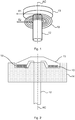
- Fig. 1 shows a perspective view of an exemplifying actuator based on a Thomson coil where there is a circular first primary coil 10 with a first and a second electrical connection terminal T1 and T2 and an armature 13.
- the turns are wound around a central coil axis AC and thereby define a center of the coil 10.
- the first primary coil may thus have windings that together define a hollow center.
- the turns of the coil may be laterally displaced from each other along the central coil axis AC and may therefore have the same radius.
- the actuator there is also an armature 13.
- the armature 13 is provided for being moved away from the coil 10 in a direction along the central coil axis AC.
- the armature 13 is furthermore joined to a rod, often termed a pull rod, and this rod 12 is provided for movement through the center of the coil 10.
- the armature 13 may for this reason be shaped as a disc, which is joined with the rod or shaft, where the rod 12 may be stretching out from the center of this disc and have a longitudinal axis A A coinciding with a central axis of this disk as well as with the central coil axis AC.
- Fig. 2 schematically shows a cross-section of the coil and armature 13 with rod 12 when placed in a housing 14.
- the housing 14 is provided with a first opening at which the coil 10 is fitted.
- the armature 13 may be placed on top of the coil 10 outside of the housing 14 with the rod 12 stretching through the first opening, through the interior of the housing 14 and out through a second opening at the bottom of the housing 14.
- the housing 14 may be rectangular in shape. However this is not necessary. What is of importance is that a magnetic flux concentrator is provided around the coil 10. This magnetic flux concentrator is furthermore in physical contact with the coil. If the coil is circular, the magnetic flux concentrator may radially surround the coil, i.e. surround the coil in the radial direction.
- the magnetic flux concentrator may be provided at least around the first opening of the housing. It is thus possible that only an annular shaped area of the housing round the first opening is a magnetic flux concentrator. It is also possible that the whole upper surface of the housing perpendicular to the coil axis AC is a magnetic flux concentrator. It is finally possible that the whole housing 14 that encloses the primary coil 10 is a magnetic flux concentrator, which is the case in the embodiment shown in fig. 2 .
- This magnetic flux concentrator may be of soft magnetic material or soft ferromagnetic material and may therefore as an example be of iron, magnetic steel or a material like permadyne.
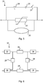
- Fig. 3 schematically shows other elements that may be a part of the actuator in order to actuate the armature.
- a capacitor bank CB comprising a number of series connected capacitors.
- the capacitor bank CB is selectively connectable to the electrical connection terminals T1 and T2 of the first primary coil 10 in order to maneuver the armature 13. For this reason, one end of the series connection is connected to the first connection terminal T1 of the primary coil 10 via an electronic switch SW1, while the other end may be directly connected to the second connection terminal T2 of the primary coil 10.
- An actuator of the type that is based on a Thomson coil may be provided for a mechanical switch. It may thus be provided for breaking or making a galvanic connection between a first and a second electrical conductor.
- Fig. 4 schematically shows one such switch where there is a first and a second conductor 16 and 18 in a vacuum, chamber 17.
- the first conductor 16 is here connected to a first switch terminal T SW1
- the second conductor 18 is connected to a second switch terminal T SW2 in order to connect the switch 20 to other electric devices.
- the second conductor 18 is fixed or stationary, while the first conductor 16 is movable.
- the rod 12 may be attached to the first conductor 16 set to move in synchronism with the armature 13. The direction of movement may also be the same. Thereby the first conductor 16 may physically connect with the second conductor 18 or vice versa.
- the armature 13 may be equipped with means that provides a downward directed force on the rod 12 and thus also forcing the first conductor 16 in galvanic contact with the second conductor 18.
- the capacitor bank CB will be controlled to provide a current pulse to the coil 10, which creates a magnetic flux that is strong enough for overcoming the downward directed force and push the armature 13 upwards and thereby the rod 12 pulls the first conductor 16 away from the second conductor 18, thereby breaking the galvanic contact between the two conductors 16 and 18.
- This type of mechanical switch may for instance be placed in a circuit breaker.
- One circuit breaker 28 that may employ the mechanical switch 20 is schematically shown in fig. 5 .
- a third branch comprising a series connection of an inductance 24, a capacitance 26 and a further switch 27.
- the further switch 27 may be provided as a combination of one or more series connected transistors with antiparallel diodes or as one or more pairs of antiparallel transistors, where the transistors may be insulated gate bipolar transistors (IGBTs).
- IGBTs insulated gate bipolar transistors
- This type of circuit breaker 28 is with advantage used for breaking the current in a power line such as a DC power line in a DC power transmission system.
- the further switch 27 is controlled to pulse the current through the mechanical switch 20 in order to obtain current zero crossings and in relation to one such zero crossing, the first and second conductors are separated from each other through the movement of the armature.
- circuit breaker is merely one type of circuit breaker in which the mechanical switch may be used. There are countless other realizations that may employ the mechanical switch.
- Fig. 6 schematically shows an example of a high voltage system where the circuit breaker 28 may be used.
- the system is here a multi-terminal DC system, such as an HVDC system comprising a number of converters converting between AC and DC.
- Each converter comprises an AC side and a DC side, where the DC side of a first converter 32 is connected to the DC side of a second converter 34 via a first DC line, the DC side of a third converter 36 is connected to the DC side of a fourth converter 38 via a second DC line.
- each circuit breaker 28 has the advantage of being fast through employing a mechanical switch based on a Thomson coil.
- the interconnection may also be considered to form a switch yard in the DC system.
- a mechanical switch being actuated by a Thomson coil based actuator of the type shown in fig. 1 - 4 is thus fast.
- the traditional Thomson coil is inefficient. This may be problematic, at least in high voltage applications.
- the magnetic flux concentrator may be made of a soft magnetic material such as iron or any other ferromagnetic media, such as for instance permadyne, and is used to boost the efficiency of the ultra-fast electromagnetic actuator.
- the housing enclosing the spiral coil that generates the magnetic field is a non-magnetic stainless steel housing that adds mechanical stability.
- a magnetic flux concentrator is used as a housing instead. This will raise the efficiency of the drive considerably. Intuitively, one may often reach the misleading conclusion that since these materials saturate they are unsuitable for use in high magnetic fields.
- the invention is based on the realization that if the actuator is to be used infrequently, which is the case if it used for a circuit breaker, then this saturation is no real problem.
- the Thomson coil has an intermittent operation. Although within such operation, high field levels the concentrator will saturate, it will still be able to help build up the flux rapidly as the concentrator provides a low magnetic reluctance flux path. Therefore, with the same current, a higher field will be generated and thus larger currents will be induced in the armature. This will result in a larger force within the same amount of time thereby significantly increasing performance.
- the magnetic flux concentrator creates a low reluctance path increasing the magnetic field and although the material of the concentrator saturates (points 2 to 3), the field in point 3 is higher than the field in point 1 (which will be the case if a non-magnetic material will be used).
- the mechanical switch is used for disconnecting a power line in the case of a fault, such as in the case of pole to ground fault, a lot of energy can be saved since these capacitors have to be constantly charged to maintain their voltage levels until the next fault appears. Moreover, if the same energizing source is decided to be kept, then the performance of the drive will be radically increased due to the concentrators.
- the concentrator should be placed in a way to close the magnetic path and reduce reluctance.
- a ferromagnetic or a magnetic flux concentrator or perhaps one of permadyne should be used. This shows the potential of using magnetic material such as iron or steel for ultra fast actuators.
- two Thomson coils are used. One may be used for making a galvanic contact and the other for breaking a galvanic contact. In this case there may be a first and a second primary coil, each placed in an opening of a corresponding housing, where one or both may act as magnetic flux concentrator. The primary coils are then facing each other where both may be centered around the same central coil axis. Through these two Thomson coils it is possible that a single armature joined with a rod is set to move between the two coils.
- FIG. 8 shows a view from above of a second type of concentrator together with a coil.
- the concentrator is annular and radially surrounds the coil 10.
- the concentrator may in this case be in the form of an annular disc 44, having a center hole in which the coil is fitted.
- Fig. 9 shows a cross-section through a third type of concentrator and coil.
- the concentrator may in this case be in the form of a solid block 46 having a cavity designed for receiving and holding the coil 10.
- the invention was above described in relation to high voltage operation. It should however be realized that it is not limited to this field.
- the actuator may this for instance be used for low, medium, and high voltage breakers.
- the actuator is actually not limited to be used in circuit breaker, but may for instance be used in a robot as well.
Description
- The present invention relates to an actuator for a mechanical switch, a mechanical switch, a circuit breaker and a high voltage power transmission system comprising such an actuator.
- In power transmission systems, there is a need for fast circuit breakers.
- Ultra-fast actuators are a new emerging technology that have been recently used as drives when there is a need of high speed actuation. One well known topology of an ultra-fast drive is the Thomson coil. A Thomson coil comprises a primary coil that induces a magnetic field, which in turn induces eddy currents in an armature. The Thomson coil has the intrinsic property of generating large impulsive forces that actuate and promptly separate the current carrying contacts of a high voltage alternating current (HVAC) circuit breaker.
- A circuit breaker of this type may, together with some extra circuitry, be used as DC circuit breaker in power transmission systems such as HVDC systems, where a system may be a multi-terminal system comprising a number of converter stations. A circuit breaker operating in a multi-terminal HVDC system or HVDC grid must be able to interrupt fault currents within some milliseconds, typically, less than 5 ms. For a Thomson coil currents in the order of several kilo Amperes are therefore required to generate a magnetic flux density in the order of several Teslas. The product of the induced current densities in the armature together with the radial component of the magnetic flux density produces the required impulsive electromagnetic forces. Due to the high currents and magnetic fields involved, a Thomson coil is often energized through the use of a capacitor bank.
-
WO 2014/000790 discloses an actuator system for actuating a high voltage current interrupter. The actuator system comprises a transmission link for transmitting kinetic energy from a force provision system to a moveable contact of the current interrupter. The transmission link has a first end which is mechanically connectable to the moveable contact of the current interrupter and a second end facing away from the moveable contact. The actuator system further comprises a damping system comprising a shock-absorbing mass. The shock-absorbing mass is located along the extension of the line of translational movement of the transmission link, at the farther side of the transmission link as seen from the current interrupter, so that upon an opening operation of the current interrupter, the second end of the transmission link will collide with the shock-absorbing mass. - In "Simulation and verification of Thomson actuator systems" by Ara Bissal, Göran Engdahl, Ener Salinas and Magnus Öhström, COMSOL Conference Paris 2010, 19 November 2010 there is disclosed a Thomson coil that can be used in an actuator. The Thomson coil is also shown together with an armature and a concentrator, where the concentrator coincides with the coil and covers any openings in it.
- The main problem of these actuators is their poor efficiency. Compared to rotating electric machines that can attain efficiencies up to 99%, traditional Thomson based ultra-fast actuators have an efficiency of 5% at best. A considerable amount of the electric energy stored in the capacitor bank is unfortunately transformed into heat.
- It would in view of this be of interest to raise the efficiency of an actuator that is based on a Thomson coil.
- The present invention addresses this situation. An object of the invention is thus to raise the efficiency of an actuator that is based on a Thomson coil.
- This object is according to a first aspect of the invention achieved through an actuator for a mechanical switch, the actuator comprising at least one armature and a first primary coil with turns wound around a central coil axis, where the armature is movable along the central coil axis and a magnetic flux concentrator is provided at least around the first primary coil.
- The object is according to a second aspect also achieved through a mechanical switch comprising a first and a second conductor and an actuator according to the first aspect, the actuator being controllable to move one of the conductors in relation to the other in order to make or break a galvanic connection between the first and second conductors.
- The object is according to a third aspect achieved through a circuit breaker connected in series with an electrical line for disconnecting the line, the circuit breaker comprising a mechanical switch according to the second aspect.
- The object is according to a fourth aspect achieved through a high voltage power transmission system comprising at least one circuit breaker according to the third aspect.
- The invention is based on the realization that magnetic flux concentrators are advantageous to be used together with Thomson coils despite the fact that magnetic flux concentrators are known to saturate. In the presence of a magnetic flux concentrator, the total magnetic reluctance of the system decreases. This leads to the creation of a larger magnetic flux in the air gap between coil and armature generating larger repulsive forces. Although the concentrator structure saturates, it will still lead to the creation of larger magnetic fields with each operation if the device being actuated using the actuator is supposed to be used with intermittent operations.
- The invention has a number of advantages. It improves the efficiency of the actuator. Due to this increased efficiency, the operating costs of the actuator may be lowered. It is for instance possible that the size of a capacitor bank used to energize the primary coil is reduced. Thereby the cost effectiveness of the actuator is increased. Also the safety is increased, since the risk of explosions is decreased and the voltage levels used may be reduced.
- The present invention will in the following be described with reference being made to the accompanying drawings, where
-
fig. 1 shows a perspective view of a Thomson coil comprising a primary coil and an armature attached to a rod for use as an actuator, -
fig. 2 schematically shows a cross-section of an actuator comprising a housing, the primary coil and the armature with rod extending through the center of the coil, -
fig. 3 schematically shows the electrical connection of the primary coil to a capacitor bank via a switch, -
fig. 4 schematically shows the use of the Thomson coil and rod in relation to a first and second conductor for forming a mechanical switch, -
fig. 5 schematically shows a circuit breaker comprising the mechanical switch offig. 4 , -
fig. 6 schematically shows a multi-terminal HVDC system where transmission lines comprise circuit breakers, -
fig. 7 shows a curve of the relationship between the magnetic flux density and the magnetic field strength of soft magnetic material and air, respectively, -
fig. 8 shows a view from above of a second variation of a coil and magnetic flux concentrator, and -
fig. 9 shows a side view of a third variation of a coil and magnetic flux concentrator. - In the following, embodiments of the invention providing the above described functionality will be described.
- The present invention is directed towards providing an actuator that may be used for actuating a mechanical switch for instance in a power transmission system, i.e. in a system for the transmission of electrical power. This system can for instance be a High Voltage Direct Current system (HVDC).
- Ultra fast actuators, such as actuators for actuating mechanical switches for instance mechanical switches in power lines, are of interest to be realized as Thomson coils. Thomson coils have the advantage of being fast, which is a requirement in many applications, for instance in some high voltage power transmission applications.
-
Fig. 1 shows a perspective view of an exemplifying actuator based on a Thomson coil where there is a circular firstprimary coil 10 with a first and a second electrical connection terminal T1 and T2 and anarmature 13. The turns are wound around a central coil axis AC and thereby define a center of thecoil 10. The first primary coil may thus have windings that together define a hollow center. The turns of the coil may be laterally displaced from each other along the central coil axis AC and may therefore have the same radius. In the actuator there is also anarmature 13. Thearmature 13 is provided for being moved away from thecoil 10 in a direction along the central coil axis AC. Thearmature 13 is furthermore joined to a rod, often termed a pull rod, and thisrod 12 is provided for movement through the center of thecoil 10. Thearmature 13 may for this reason be shaped as a disc, which is joined with the rod or shaft, where therod 12 may be stretching out from the center of this disc and have a longitudinal axis AA coinciding with a central axis of this disk as well as with the central coil axis AC. -
Fig. 2 schematically shows a cross-section of the coil andarmature 13 withrod 12 when placed in ahousing 14. Thehousing 14 is provided with a first opening at which thecoil 10 is fitted. Thearmature 13 may be placed on top of thecoil 10 outside of thehousing 14 with therod 12 stretching through the first opening, through the interior of thehousing 14 and out through a second opening at the bottom of thehousing 14. Thehousing 14 may be rectangular in shape. However this is not necessary. What is of importance is that a magnetic flux concentrator is provided around thecoil 10. This magnetic flux concentrator is furthermore in physical contact with the coil. If the coil is circular, the magnetic flux concentrator may radially surround the coil, i.e. surround the coil in the radial direction. In the exemplifying housing the magnetic flux concentrator may be provided at least around the first opening of the housing. It is thus possible that only an annular shaped area of the housing round the first opening is a magnetic flux concentrator. It is also possible that the whole upper surface of the housing perpendicular to the coil axis AC is a magnetic flux concentrator. It is finally possible that thewhole housing 14 that encloses theprimary coil 10 is a magnetic flux concentrator, which is the case in the embodiment shown infig. 2 . This magnetic flux concentrator may be of soft magnetic material or soft ferromagnetic material and may therefore as an example be of iron, magnetic steel or a material like permadyne. -
Fig. 3 schematically shows other elements that may be a part of the actuator in order to actuate the armature. There is here a capacitor bank CB comprising a number of series connected capacitors. The capacitor bank CB is selectively connectable to the electrical connection terminals T1 and T2 of the firstprimary coil 10 in order to maneuver thearmature 13. For this reason, one end of the series connection is connected to the first connection terminal T1 of theprimary coil 10 via an electronic switch SW1, while the other end may be directly connected to the second connection terminal T2 of theprimary coil 10. - An actuator of the type that is based on a Thomson coil may be provided for a mechanical switch. It may thus be provided for breaking or making a galvanic connection between a first and a second electrical conductor.
Fig. 4 schematically shows one such switch where there is a first and asecond conductor chamber 17. Thefirst conductor 16 is here connected to a first switch terminal TSW1, while thesecond conductor 18 is connected to a second switch terminal TSW2 in order to connect theswitch 20 to other electric devices. In thisswitch 20 thesecond conductor 18 is fixed or stationary, while thefirst conductor 16 is movable. Therod 12 may be attached to thefirst conductor 16 set to move in synchronism with thearmature 13. The direction of movement may also be the same. Thereby thefirst conductor 16 may physically connect with thesecond conductor 18 or vice versa. Through the above mentioned type of movement galvanic contact between the first andsecond conductor - In the exemplifying
switch 20, thearmature 13 may be equipped with means that provides a downward directed force on therod 12 and thus also forcing thefirst conductor 16 in galvanic contact with thesecond conductor 18. In operation of the Thomson coil, the capacitor bank CB will be controlled to provide a current pulse to thecoil 10, which creates a magnetic flux that is strong enough for overcoming the downward directed force and push thearmature 13 upwards and thereby therod 12 pulls thefirst conductor 16 away from thesecond conductor 18, thereby breaking the galvanic contact between the twoconductors - This type of mechanical switch may for instance be placed in a circuit breaker. One
circuit breaker 28 that may employ themechanical switch 20 is schematically shown infig. 5 . There is here a first branch with themechanical switch 20. In parallel with this first branch there is a second branch with anonlinear resistor 22, such as a varistor. In parallel with both the first and second branches there is a third branch comprising a series connection of aninductance 24, acapacitance 26 and afurther switch 27. - The
further switch 27 may be provided as a combination of one or more series connected transistors with antiparallel diodes or as one or more pairs of antiparallel transistors, where the transistors may be insulated gate bipolar transistors (IGBTs). - This type of
circuit breaker 28 is with advantage used for breaking the current in a power line such as a DC power line in a DC power transmission system. In this case thefurther switch 27 is controlled to pulse the current through themechanical switch 20 in order to obtain current zero crossings and in relation to one such zero crossing, the first and second conductors are separated from each other through the movement of the armature. - It should be realized that the above-described circuit breaker is merely one type of circuit breaker in which the mechanical switch may be used. There are countless other realizations that may employ the mechanical switch.
-
Fig. 6 schematically shows an example of a high voltage system where thecircuit breaker 28 may be used. The system is here a multi-terminal DC system, such as an HVDC system comprising a number of converters converting between AC and DC. Each converter comprises an AC side and a DC side, where the DC side of afirst converter 32 is connected to the DC side of asecond converter 34 via a first DC line, the DC side of athird converter 36 is connected to the DC side of afourth converter 38 via a second DC line. There is also a third DC line interconnecting the DC sides of the first and thethird converters fourth converters circuit breaker 28, for instance of the type shown infig 5 . Eachcircuit breaker 28 has the advantage of being fast through employing a mechanical switch based on a Thomson coil. The interconnection may also be considered to form a switch yard in the DC system. - A mechanical switch being actuated by a Thomson coil based actuator of the type shown in
fig. 1 - 4 is thus fast. However, as is stated initially the traditional Thomson coil is inefficient. This may be problematic, at least in high voltage applications. - To improve the electric to mechanical energy conversion process, it is here proposed to use a magnetic flux concentrator in the actuator. As stated earlier, the magnetic flux concentrator may be made of a soft magnetic material such as iron or any other ferromagnetic media, such as for instance permadyne, and is used to boost the efficiency of the ultra-fast electromagnetic actuator.
- This is a new concept especially for applications involving such high magnetic field levels, for instance above 5 Teslas, or around 10 Teslas and above. Traditionally, the housing enclosing the spiral coil that generates the magnetic field is a non-magnetic stainless steel housing that adds mechanical stability. According to the first embodiment a magnetic flux concentrator is used as a housing instead. This will raise the efficiency of the drive considerably. Intuitively, one may often reach the misleading conclusion that since these materials saturate they are unsuitable for use in high magnetic fields.
- The invention is based on the realization that if the actuator is to be used infrequently, which is the case if it used for a circuit breaker, then this saturation is no real problem.
- Unlike transformers or motors, the Thomson coil has an intermittent operation. Although within such operation, high field levels the concentrator will saturate, it will still be able to help build up the flux rapidly as the concentrator provides a low magnetic reluctance flux path. Therefore, with the same current, a higher field will be generated and thus larger currents will be induced in the armature. This will result in a larger force within the same amount of time thereby significantly increasing performance.
- In the presence of a magnetic concentrator, the total magnetic reluctance of the system decreases. This leads to the creation of a larger magnetic flux in the air gap between coil and armature generating larger repulsive forces than without such a concentrator. Although the concentrator structure saturates, it will still lead to the creation of larger magnetic fields with each operation since the circuit breaker is supposed to be used with intermittent operations.
- This can be understood from looking at
fig. 7 , which shows acurve 40 of the relationship between the magnetic flux density B and the magnetic field strength H of soft magnetic material and acurve 42 of the relationship between the magnetic flux density B and the magnetic field strength H of air. - The magnetic flux concentrator creates a low reluctance path increasing the magnetic field and although the material of the concentrator saturates (
points 2 to 3), the field inpoint 3 is higher than the field in point 1 (which will be the case if a non-magnetic material will be used). - The use of a magnetic flux concentrator raises the efficiency considerably. Due to this increased efficiency, the operating costs of the actuator may be considerably lowered. It is for instance possible that the size of the capacitor bank is reduced. The lower the number of capacitors, the more cost effective the actuator is, and the safer it is since this decreases the risk of explosions. It also adds to the safety though the use of a lower voltage.
- If the mechanical switch is used for disconnecting a power line in the case of a fault, such as in the case of pole to ground fault, a lot of energy can be saved since these capacitors have to be constantly charged to maintain their voltage levels until the next fault appears. Moreover, if the same energizing source is decided to be kept, then the performance of the drive will be radically increased due to the concentrators.
- Ideally, the concentrator should be placed in a way to close the magnetic path and reduce reluctance. Instead of using mechanically strong non metallic materials (e.g. Bakelite, concrete, fiber glass) or non-magnetic stainless steel, a ferromagnetic or a magnetic flux concentrator or perhaps one of permadyne should be used. This shows the potential of using magnetic material such as iron or steel for ultra fast actuators.
- It is possible that two Thomson coils are used. One may be used for making a galvanic contact and the other for breaking a galvanic contact. In this case there may be a first and a second primary coil, each placed in an opening of a corresponding housing, where one or both may act as magnetic flux concentrator. The primary coils are then facing each other where both may be centered around the same central coil axis. Through these two Thomson coils it is possible that a single armature joined with a rod is set to move between the two coils.
- In the first embodiment described above the concentrator was a part of a housing. It should be realized that the invention is not limited to this concept.
Fig. 8 shows a view from above of a second type of concentrator together with a coil. In this case the concentrator is annular and radially surrounds thecoil 10. The concentrator may in this case be in the form of anannular disc 44, having a center hole in which the coil is fitted. -
Fig. 9 shows a cross-section through a third type of concentrator and coil. The concentrator may in this case be in the form of asolid block 46 having a cavity designed for receiving and holding thecoil 10. - The invention was above described in relation to high voltage operation. It should however be realized that it is not limited to this field. The actuator may this for instance be used for low, medium, and high voltage breakers. The actuator is actually not limited to be used in circuit breaker, but may for instance be used in a robot as well.
Claims (11)
- An actuator for a mechanical switch, said actuator comprising at least one armature (13) connected to a rod (12), a first primary coil (10) with turns wound around a central coil axis (AC) defining a center of the coil and a first housing (14) for receiving the rod and provided with a first opening, the actuator being based on a Thomson coil, the first coil being fitted at the first opening and the armature being placed on top of the coil and movable away from the coil in a direction along the central coil axis with the rod provided for movement through the center of the coil, characterised by the armature being placed outside of the housing and said actuator further comprising a magnetic flux concentrator made up of at least a part of the first housing, said magnetic flux concentrator being provided at least around the first opening of the housing and at least around the first primary coil and in physical contact with the first primary coil.
- The actuator according to claim 1, wherein the whole housing is a magnetic flux concentrator.
- The actuator according to any previous claim, wherein the material of the magnetic flux concentrator is a soft magnetic material.
- The actuator according to any previous claim, wherein the first primary coil (10) has electrical connection terminals (T1, T2) and further comprising a capacitor bank (CB) selectively connectable to the electrical connection terminals of the first primary coil in order to maneuver the armature (13).
- The actuator according to claim 4, further comprising an electrical switch (SW1) for selectively connecting the capacitor bank (CB) to the electrical connection terminals (T1, T2).
- The actuator according to any previous claim, further comprising a second primary coil of the same structure as the first primary coil, where the second primary coil is centered around said central coil axis for allowing the armature to be moved back and forth between the first and second primary coils.
- A mechanical switch (20) comprising a first and a second conductor (16, 18) and an actuator according to any previous claim, said actuator being controllable to move one of the conductors (16) in relation to the other (18) in order to make or break a galvanic connection between the first and second conductors.
- A circuit breaker (28) connected in series with an electrical line for disconnecting the line, the circuit breaker comprising a mechanical switch (20) according to claim 7.
- A high voltage power transmission system (30) comprising at least one circuit breaker (28) according to claim 8.
- The high voltage power transmission system according to claim 9, wherein the system is a multi-terminal high voltage power transmission system.
- The high voltage power transmission system according to claim 9 or 10, wherein the system is a DC system.
Applications Claiming Priority (1)
| Application Number | Priority Date | Filing Date | Title |
|---|---|---|---|
| PCT/EP2014/059859 WO2015172824A1 (en) | 2014-05-14 | 2014-05-14 | Thomson coil based actuator |
Publications (2)
| Publication Number | Publication Date |
|---|---|
| EP3143631A1 EP3143631A1 (en) | 2017-03-22 |
| EP3143631B1 true EP3143631B1 (en) | 2018-05-09 |
Family
ID=50732170
Family Applications (1)
| Application Number | Title | Priority Date | Filing Date |
|---|---|---|---|
| EP14724427.1A Active EP3143631B1 (en) | 2014-05-14 | 2014-05-14 | Thomson coil based actuator |
Country Status (4)
| Country | Link |
|---|---|
| US (1) | US9911562B2 (en) |
| EP (1) | EP3143631B1 (en) |
| CN (1) | CN106663554B (en) |
| WO (1) | WO2015172824A1 (en) |
Families Citing this family (16)
| Publication number | Priority date | Publication date | Assignee | Title |
|---|---|---|---|---|
| EP3143631B1 (en) * | 2014-05-14 | 2018-05-09 | ABB Schweiz AG | Thomson coil based actuator |
| KR20190111914A (en) * | 2016-12-06 | 2019-10-02 | 힐티 악티엔게젤샤프트 | Electric power propeller |
| EP3594972B1 (en) * | 2018-07-13 | 2023-10-04 | ABB Schweiz AG | Drive for a low-, medium-, or high-voltage switchgear, and method for operating the same |
| US10580599B1 (en) | 2018-08-21 | 2020-03-03 | Eaton Intelligent Power Limited | Vacuum circuit interrupter with actuation having active damping |
| SE1851084A1 (en) | 2018-09-14 | 2020-03-15 | Scibreak Ab | Current interrupter with actuator run-time control |
| CN109671595B (en) * | 2019-01-08 | 2020-01-14 | 程丽娜 | Switch |
| US11069495B2 (en) * | 2019-01-25 | 2021-07-20 | Eaton Intelligent Power Limited | Vacuum switching apparatus and drive mechanism therefor |
| US10796868B2 (en) | 2019-02-11 | 2020-10-06 | Eaton Intelligent Power Limited | Thomson coil integrated moving contact in vacuum interrupter |
| US11152174B2 (en) | 2019-06-19 | 2021-10-19 | Eaton Intelligent Power Limited | Dual thomson coil-actuated, double-bellows vacuum circuit interrupter |
| US11328884B2 (en) | 2019-06-26 | 2022-05-10 | Eaton Intelligent Power Limited | Variable-speed circuit breaker and switching method for same |
| US11107653B2 (en) | 2019-06-26 | 2021-08-31 | Eaton Intelligent Power Limited | Dual-action switching mechanism and pole unit for circuit breaker |
| US11289294B2 (en) | 2019-07-10 | 2022-03-29 | Eaton Intelligent Power Limited | Rotary switch and circuit interrupter including the same |
| EP3913647B1 (en) * | 2020-05-22 | 2023-02-22 | ABB Schweiz AG | A switch system |
| US11183348B1 (en) | 2020-07-21 | 2021-11-23 | Eaton Intelligent Power Limited | Vacuum circuit interrupter with decelerator with integrated latch assembly |
| US11749477B2 (en) | 2021-04-21 | 2023-09-05 | Eaton Intelligent Power Limited | Vacuum circuit interrupter with dual plate actuation |
| WO2022261565A2 (en) * | 2021-06-11 | 2022-12-15 | Helion Energy, Inc. | High-speed switching apparatus for electromagnetic coils |
Family Cites Families (40)
| Publication number | Priority date | Publication date | Assignee | Title |
|---|---|---|---|---|
| GB1229799A (en) * | 1967-11-13 | 1971-04-28 | ||
| US3525963A (en) * | 1968-07-25 | 1970-08-25 | English Electric Co Ltd | Electro-magnetic actuator with armature assembly slidable between two limit positions |
| US4215328A (en) * | 1978-04-17 | 1980-07-29 | Square D Company | Circuit breaker having an electronic fault sensing and trip initiating unit |
| ATE21296T1 (en) * | 1981-12-14 | 1986-08-15 | Sprecher & Schuh Ag | PAIR OF IRON CORE AND COIL FOR AC CONTACTOR. |
| DE3942542A1 (en) * | 1989-12-22 | 1991-06-27 | Lungu Cornelius | BISTABLE MAGNETIC DRIVE WITH PERMANENT MAGNETIC HUBANKER |
| EP0563774B1 (en) * | 1992-03-31 | 1999-05-19 | Ellenberger & Poensgen GmbH | Protective circuit breaker with remote control |
| US5281936A (en) * | 1992-06-01 | 1994-01-25 | Teledyne Industries, Inc. | Microwave switch |
| US5488340A (en) | 1994-05-20 | 1996-01-30 | Caterpillar Inc. | Hard magnetic valve actuator adapted for a fuel injector |
| US5652558A (en) * | 1996-04-10 | 1997-07-29 | The Narda Microwave Corporation | Double pole double throw RF switch |
| SE9901627D0 (en) * | 1999-05-03 | 1999-05-03 | Asea Brown Boveri | Switchgear |
| WO2001078210A1 (en) * | 2000-04-07 | 2001-10-18 | Siemens Aktiengesellschaft | Switching method for an electromagnetic switching device and an electromagnetic switching device corresponding thereto |
| JP2002124162A (en) | 2000-10-16 | 2002-04-26 | Mitsubishi Electric Corp | Switchgear |
| DE10214992A1 (en) * | 2002-04-05 | 2003-10-16 | Moeller Gmbh | AC electromagnet |
| US6657150B1 (en) * | 2002-06-14 | 2003-12-02 | Eaton Corporation | Shorting switch and system to eliminate arcing faults in power distribution equipment |
| CN1253912C (en) * | 2003-05-29 | 2006-04-26 | 刘平 | Electric power switch apparatus |
| DE102004004708B3 (en) * | 2004-01-30 | 2005-04-21 | Karl Dungs Gmbh & Co. Kg | Magnetically-operated double-seat valve for shutting off fluid flow has armature moving circular seal engaging triangular-section seat and surrounding inner valve with triangular-section seal |
| US7777600B2 (en) | 2004-05-20 | 2010-08-17 | Powerpath Technologies Llc | Eddy current inductive drive electromechanical liner actuator and switching arrangement |
| DE102005013197A1 (en) * | 2005-03-16 | 2006-09-28 | Siemens Ag | Magnetic actuator |
| US20060226941A1 (en) * | 2005-03-30 | 2006-10-12 | Dimig Steven J | Residual magnetic devices and methods |
| US20060226942A1 (en) * | 2005-03-30 | 2006-10-12 | Dimig Steven J | Residual magnetic devices and methods |
| US7401483B2 (en) * | 2005-03-30 | 2008-07-22 | Strattec Security Corporation | Residual magnetic devices and methods for an ignition actuation blockage device |
| US20060238285A1 (en) * | 2005-03-30 | 2006-10-26 | Dimig Steven J | Residual magnetic devices and methods |
| GB0607072D0 (en) | 2006-04-07 | 2006-05-17 | Artemis Intelligent Power Ltd | Electromagnetic actuator |
| WO2008141198A1 (en) * | 2007-05-09 | 2008-11-20 | Motor Excellence, Llc | Electrical output generating and driven devices using disk and non-disk shaped rotors, and methods of making and using the same |
| US8139328B2 (en) * | 2007-05-17 | 2012-03-20 | Levitron Manufacturing Company, Inc. | Fault circuit interrupting device with symmetrical inputs |
| US7830231B2 (en) * | 2008-02-18 | 2010-11-09 | Eaton Corporation | Trip actuator including a thermoplastic bushing, and trip unit and electrical switching apparatus including the same |
| EP2182531B1 (en) | 2008-10-29 | 2014-01-08 | Sauer-Danfoss ApS | Valve actuator |
| TWI351325B (en) | 2008-12-09 | 2011-11-01 | Metal Ind Res & Dev Ct | Device for producing patterns and a method thereof |
| DE102009031665B4 (en) | 2009-07-05 | 2016-02-25 | Msm Krystall Gbr (Vertretungsberechtigte Gesellschafter: Dr. Rainer Schneider, 12165 Berlin; Arno Mecklenburg, 10999 Berlin) | Electrodynamic actuator |
| EP2312606B1 (en) * | 2009-10-14 | 2013-02-27 | ABB Technology AG | Circuit-breaker with a common housing |
| DE202011050847U1 (en) * | 2010-10-16 | 2011-11-21 | Msm Krystall Gbr (Vertretungsberechtigte Gesellschafter: Dr. Rainer Schneider, 12165 Berlin; Arno Mecklenburg, 10999 Berlin) | Electromagnetic linear actuator |
| US8729416B2 (en) * | 2012-01-23 | 2014-05-20 | Electro-Mechanical Corporation | Circuit breaker remote tripping |
| US20130328650A1 (en) * | 2012-06-06 | 2013-12-12 | Glen A Robertson | Divergent flux path magnetic actuator and devices incorporating the same |
| EP2867909B1 (en) * | 2012-06-27 | 2016-04-06 | ABB Technology Ltd. | A high voltage current interrupted and an actuator system for a high voltage current interruptor |
| EP2907146B1 (en) * | 2012-10-12 | 2020-05-27 | Rhefor GbR | Scalable, highly dynamic electromagnetic linear drive with limited travel and low transverse forces |
| US9036320B1 (en) * | 2013-12-02 | 2015-05-19 | Elbex Video Ltd. | Mechanical latching relays and hybrid switches with latching relays for use in electrical automation |
| GB2522696A (en) * | 2014-02-03 | 2015-08-05 | Gen Electric | Improvements in or relating to vacuum switching devices |
| EP3143631B1 (en) * | 2014-05-14 | 2018-05-09 | ABB Schweiz AG | Thomson coil based actuator |
| CN107077988B (en) * | 2014-06-02 | 2019-07-16 | Abb瑞士股份有限公司 | High voltage puffer circuit breaker and breaker unit with this puffer circuit breaker |
| US9548174B2 (en) * | 2015-04-23 | 2017-01-17 | Tyco Electronics Corporation | Contractor assembly which counteracts electromagnetic repulsion of contacts |
-
2014
- 2014-05-14 EP EP14724427.1A patent/EP3143631B1/en active Active
- 2014-05-14 WO PCT/EP2014/059859 patent/WO2015172824A1/en active Application Filing
- 2014-05-14 US US15/308,774 patent/US9911562B2/en active Active
- 2014-05-14 CN CN201480078868.1A patent/CN106663554B/en active Active
Non-Patent Citations (1)
| Title |
|---|
| None * |
Also Published As
| Publication number | Publication date |
|---|---|
| WO2015172824A1 (en) | 2015-11-19 |
| CN106663554A (en) | 2017-05-10 |
| US9911562B2 (en) | 2018-03-06 |
| EP3143631A1 (en) | 2017-03-22 |
| CN106663554B (en) | 2018-06-01 |
| US20170154747A1 (en) | 2017-06-01 |
Similar Documents
| Publication | Publication Date | Title |
|---|---|---|
| EP3143631B1 (en) | Thomson coil based actuator | |
| EP3043368B1 (en) | Bypass switch for hvdc transmission | |
| Puumala et al. | Electromagnetic design of ultrafast electromechanical switches | |
| CN107946133B (en) | Quick separating brake mechanism and hybrid alternating current circuit breaker | |
| US10325737B2 (en) | Fast switch device | |
| KR20210118060A (en) | Multiple Hammer Strike Vacuum Interrupter Weld Break | |
| CN110828226A (en) | Electromagnetic repulsion device and quick switch | |
| Vilchis-Rodriguez et al. | Finite element analysis and efficiency improvement of the Thomson coil actuator | |
| WO2015062644A1 (en) | Circuit breaker | |
| KR101841859B1 (en) | A circuit breaker unit with electromagnetic drive | |
| WO2014048483A1 (en) | Electrical switch with thomson coil drive | |
| Vilchis-Rodriguez et al. | Double-sided Thomson coil based actuator: Finite element design and performance analysis | |
| US11621135B2 (en) | Armature for electromagnetic actuator, an electromagnetic actuator, a switch device and a method for manufacturing an armature | |
| WO2012045360A1 (en) | Direct current circuit breaker | |
| CN108573828B (en) | Switching device for medium-voltage switchgear assemblies | |
| CN201741623U (en) | Outdoor high-voltage intelligent permanent magnetic vacuum switch | |
| KR20210072104A (en) | Manual Closing Auxiliary Control Mechanism | |
| EP3531435A1 (en) | On-load tap changing device and on-load tap changing system | |
| Yin et al. | A comparison between moving magnet and moving coil actuators for vacuum interrupters | |
| Yin et al. | Novel fast operating moving coil actuator with compensation coil for HVDC circuit breakers | |
| Sonagra et al. | Controlled switching of non-coupled & coupled reactor for re-ignition free de-energization operation | |
| Parekh et al. | Study of an electromagnetic damping actuator | |
| CN112820580A (en) | Strap type transverse magnetic field direct current transfer device and application thereof | |
| CN213124280U (en) | Circuit breaker | |
| US20230011724A1 (en) | Magnetic latching actuator |
Legal Events
| Date | Code | Title | Description |
|---|---|---|---|
| PUAI | Public reference made under article 153(3) epc to a published international application that has entered the european phase |
Free format text: ORIGINAL CODE: 0009012 |
|
| 17P | Request for examination filed |
Effective date: 20161214 |
|
| AK | Designated contracting states |
Kind code of ref document: A1 Designated state(s): AL AT BE BG CH CY CZ DE DK EE ES FI FR GB GR HR HU IE IS IT LI LT LU LV MC MK MT NL NO PL PT RO RS SE SI SK SM TR |
|
| AX | Request for extension of the european patent |
Extension state: BA ME |
|
| DAX | Request for extension of the european patent (deleted) | ||
| GRAP | Despatch of communication of intention to grant a patent |
Free format text: ORIGINAL CODE: EPIDOSNIGR1 |
|
| INTG | Intention to grant announced |
Effective date: 20171212 |
|
| GRAS | Grant fee paid |
Free format text: ORIGINAL CODE: EPIDOSNIGR3 |
|
| GRAA | (expected) grant |
Free format text: ORIGINAL CODE: 0009210 |
|
| AK | Designated contracting states |
Kind code of ref document: B1 Designated state(s): AL AT BE BG CH CY CZ DE DK EE ES FI FR GB GR HR HU IE IS IT LI LT LU LV MC MK MT NL NO PL PT RO RS SE SI SK SM TR |
|
| REG | Reference to a national code |
Ref country code: GB Ref legal event code: FG4D |
|
| REG | Reference to a national code |
Ref country code: CH Ref legal event code: EP Ref country code: AT Ref legal event code: REF Ref document number: 998275 Country of ref document: AT Kind code of ref document: T Effective date: 20180515 |
|
| REG | Reference to a national code |
Ref country code: DE Ref legal event code: R096 Ref document number: 602014025218 Country of ref document: DE Ref country code: IE Ref legal event code: FG4D |
|
| REG | Reference to a national code |
Ref country code: DE Ref legal event code: R084 Ref document number: 602014025218 Country of ref document: DE |
|
| REG | Reference to a national code |
Ref country code: NL Ref legal event code: MP Effective date: 20180509 |
|
| REG | Reference to a national code |
Ref country code: LT Ref legal event code: MG4D |
|
| PG25 | Lapsed in a contracting state [announced via postgrant information from national office to epo] |
Ref country code: ES Free format text: LAPSE BECAUSE OF FAILURE TO SUBMIT A TRANSLATION OF THE DESCRIPTION OR TO PAY THE FEE WITHIN THE PRESCRIBED TIME-LIMIT Effective date: 20180509 Ref country code: LT Free format text: LAPSE BECAUSE OF FAILURE TO SUBMIT A TRANSLATION OF THE DESCRIPTION OR TO PAY THE FEE WITHIN THE PRESCRIBED TIME-LIMIT Effective date: 20180509 Ref country code: FI Free format text: LAPSE BECAUSE OF FAILURE TO SUBMIT A TRANSLATION OF THE DESCRIPTION OR TO PAY THE FEE WITHIN THE PRESCRIBED TIME-LIMIT Effective date: 20180509 Ref country code: NO Free format text: LAPSE BECAUSE OF FAILURE TO SUBMIT A TRANSLATION OF THE DESCRIPTION OR TO PAY THE FEE WITHIN THE PRESCRIBED TIME-LIMIT Effective date: 20180809 Ref country code: BG Free format text: LAPSE BECAUSE OF FAILURE TO SUBMIT A TRANSLATION OF THE DESCRIPTION OR TO PAY THE FEE WITHIN THE PRESCRIBED TIME-LIMIT Effective date: 20180809 Ref country code: SE Free format text: LAPSE BECAUSE OF FAILURE TO SUBMIT A TRANSLATION OF THE DESCRIPTION OR TO PAY THE FEE WITHIN THE PRESCRIBED TIME-LIMIT Effective date: 20180509 |
|
| PG25 | Lapsed in a contracting state [announced via postgrant information from national office to epo] |
Ref country code: RS Free format text: LAPSE BECAUSE OF FAILURE TO SUBMIT A TRANSLATION OF THE DESCRIPTION OR TO PAY THE FEE WITHIN THE PRESCRIBED TIME-LIMIT Effective date: 20180509 Ref country code: LV Free format text: LAPSE BECAUSE OF FAILURE TO SUBMIT A TRANSLATION OF THE DESCRIPTION OR TO PAY THE FEE WITHIN THE PRESCRIBED TIME-LIMIT Effective date: 20180509 Ref country code: HR Free format text: LAPSE BECAUSE OF FAILURE TO SUBMIT A TRANSLATION OF THE DESCRIPTION OR TO PAY THE FEE WITHIN THE PRESCRIBED TIME-LIMIT Effective date: 20180509 Ref country code: GR Free format text: LAPSE BECAUSE OF FAILURE TO SUBMIT A TRANSLATION OF THE DESCRIPTION OR TO PAY THE FEE WITHIN THE PRESCRIBED TIME-LIMIT Effective date: 20180810 Ref country code: NL Free format text: LAPSE BECAUSE OF FAILURE TO SUBMIT A TRANSLATION OF THE DESCRIPTION OR TO PAY THE FEE WITHIN THE PRESCRIBED TIME-LIMIT Effective date: 20180509 |
|
| REG | Reference to a national code |
Ref country code: CH Ref legal event code: PL |
|
| REG | Reference to a national code |
Ref country code: AT Ref legal event code: MK05 Ref document number: 998275 Country of ref document: AT Kind code of ref document: T Effective date: 20180509 |
|
| REG | Reference to a national code |
Ref country code: BE Ref legal event code: MM Effective date: 20180531 |
|
| PG25 | Lapsed in a contracting state [announced via postgrant information from national office to epo] |
Ref country code: RO Free format text: LAPSE BECAUSE OF FAILURE TO SUBMIT A TRANSLATION OF THE DESCRIPTION OR TO PAY THE FEE WITHIN THE PRESCRIBED TIME-LIMIT Effective date: 20180509 Ref country code: CZ Free format text: LAPSE BECAUSE OF FAILURE TO SUBMIT A TRANSLATION OF THE DESCRIPTION OR TO PAY THE FEE WITHIN THE PRESCRIBED TIME-LIMIT Effective date: 20180509 Ref country code: SK Free format text: LAPSE BECAUSE OF FAILURE TO SUBMIT A TRANSLATION OF THE DESCRIPTION OR TO PAY THE FEE WITHIN THE PRESCRIBED TIME-LIMIT Effective date: 20180509 Ref country code: PL Free format text: LAPSE BECAUSE OF FAILURE TO SUBMIT A TRANSLATION OF THE DESCRIPTION OR TO PAY THE FEE WITHIN THE PRESCRIBED TIME-LIMIT Effective date: 20180509 Ref country code: DK Free format text: LAPSE BECAUSE OF FAILURE TO SUBMIT A TRANSLATION OF THE DESCRIPTION OR TO PAY THE FEE WITHIN THE PRESCRIBED TIME-LIMIT Effective date: 20180509 Ref country code: EE Free format text: LAPSE BECAUSE OF FAILURE TO SUBMIT A TRANSLATION OF THE DESCRIPTION OR TO PAY THE FEE WITHIN THE PRESCRIBED TIME-LIMIT Effective date: 20180509 Ref country code: AT Free format text: LAPSE BECAUSE OF FAILURE TO SUBMIT A TRANSLATION OF THE DESCRIPTION OR TO PAY THE FEE WITHIN THE PRESCRIBED TIME-LIMIT Effective date: 20180509 |
|
| REG | Reference to a national code |
Ref country code: DE Ref legal event code: R097 Ref document number: 602014025218 Country of ref document: DE |
|
| REG | Reference to a national code |
Ref country code: IE Ref legal event code: MM4A |
|
| PG25 | Lapsed in a contracting state [announced via postgrant information from national office to epo] |
Ref country code: SM Free format text: LAPSE BECAUSE OF FAILURE TO SUBMIT A TRANSLATION OF THE DESCRIPTION OR TO PAY THE FEE WITHIN THE PRESCRIBED TIME-LIMIT Effective date: 20180509 Ref country code: LI Free format text: LAPSE BECAUSE OF NON-PAYMENT OF DUE FEES Effective date: 20180531 Ref country code: CH Free format text: LAPSE BECAUSE OF NON-PAYMENT OF DUE FEES Effective date: 20180531 Ref country code: IT Free format text: LAPSE BECAUSE OF FAILURE TO SUBMIT A TRANSLATION OF THE DESCRIPTION OR TO PAY THE FEE WITHIN THE PRESCRIBED TIME-LIMIT Effective date: 20180509 |
|
| PLBE | No opposition filed within time limit |
Free format text: ORIGINAL CODE: 0009261 |
|
| STAA | Information on the status of an ep patent application or granted ep patent |
Free format text: STATUS: NO OPPOSITION FILED WITHIN TIME LIMIT |
|
| PG25 | Lapsed in a contracting state [announced via postgrant information from national office to epo] |
Ref country code: MC Free format text: LAPSE BECAUSE OF FAILURE TO SUBMIT A TRANSLATION OF THE DESCRIPTION OR TO PAY THE FEE WITHIN THE PRESCRIBED TIME-LIMIT Effective date: 20180509 Ref country code: LU Free format text: LAPSE BECAUSE OF NON-PAYMENT OF DUE FEES Effective date: 20180514 |
|
| 26N | No opposition filed |
Effective date: 20190212 |
|
| GBPC | Gb: european patent ceased through non-payment of renewal fee |
Effective date: 20180809 |
|
| PG25 | Lapsed in a contracting state [announced via postgrant information from national office to epo] |
Ref country code: FR Free format text: LAPSE BECAUSE OF NON-PAYMENT OF DUE FEES Effective date: 20180709 Ref country code: IE Free format text: LAPSE BECAUSE OF NON-PAYMENT OF DUE FEES Effective date: 20180514 |
|
| PG25 | Lapsed in a contracting state [announced via postgrant information from national office to epo] |
Ref country code: BE Free format text: LAPSE BECAUSE OF NON-PAYMENT OF DUE FEES Effective date: 20180531 Ref country code: SI Free format text: LAPSE BECAUSE OF FAILURE TO SUBMIT A TRANSLATION OF THE DESCRIPTION OR TO PAY THE FEE WITHIN THE PRESCRIBED TIME-LIMIT Effective date: 20180509 |
|
| PG25 | Lapsed in a contracting state [announced via postgrant information from national office to epo] |
Ref country code: GB Free format text: LAPSE BECAUSE OF NON-PAYMENT OF DUE FEES Effective date: 20180809 |
|
| PG25 | Lapsed in a contracting state [announced via postgrant information from national office to epo] |
Ref country code: AL Free format text: LAPSE BECAUSE OF FAILURE TO SUBMIT A TRANSLATION OF THE DESCRIPTION OR TO PAY THE FEE WITHIN THE PRESCRIBED TIME-LIMIT Effective date: 20180509 |
|
| PG25 | Lapsed in a contracting state [announced via postgrant information from national office to epo] |
Ref country code: MT Free format text: LAPSE BECAUSE OF NON-PAYMENT OF DUE FEES Effective date: 20180514 |
|
| PG25 | Lapsed in a contracting state [announced via postgrant information from national office to epo] |
Ref country code: TR Free format text: LAPSE BECAUSE OF FAILURE TO SUBMIT A TRANSLATION OF THE DESCRIPTION OR TO PAY THE FEE WITHIN THE PRESCRIBED TIME-LIMIT Effective date: 20180509 |
|
| PG25 | Lapsed in a contracting state [announced via postgrant information from national office to epo] |
Ref country code: PT Free format text: LAPSE BECAUSE OF FAILURE TO SUBMIT A TRANSLATION OF THE DESCRIPTION OR TO PAY THE FEE WITHIN THE PRESCRIBED TIME-LIMIT Effective date: 20180509 |
|
| PG25 | Lapsed in a contracting state [announced via postgrant information from national office to epo] |
Ref country code: MK Free format text: LAPSE BECAUSE OF NON-PAYMENT OF DUE FEES Effective date: 20180509 Ref country code: HU Free format text: LAPSE BECAUSE OF FAILURE TO SUBMIT A TRANSLATION OF THE DESCRIPTION OR TO PAY THE FEE WITHIN THE PRESCRIBED TIME-LIMIT; INVALID AB INITIO Effective date: 20140514 Ref country code: CY Free format text: LAPSE BECAUSE OF FAILURE TO SUBMIT A TRANSLATION OF THE DESCRIPTION OR TO PAY THE FEE WITHIN THE PRESCRIBED TIME-LIMIT Effective date: 20180509 |
|
| PG25 | Lapsed in a contracting state [announced via postgrant information from national office to epo] |
Ref country code: IS Free format text: LAPSE BECAUSE OF FAILURE TO SUBMIT A TRANSLATION OF THE DESCRIPTION OR TO PAY THE FEE WITHIN THE PRESCRIBED TIME-LIMIT Effective date: 20180909 |
|
| PGFP | Annual fee paid to national office [announced via postgrant information from national office to epo] |
Ref country code: DE Payment date: 20230519 Year of fee payment: 10 |