EP3038250A1 - Power convertor, controller, and method for changing carrier frequency - Google Patents
Power convertor, controller, and method for changing carrier frequency Download PDFInfo
- Publication number
- EP3038250A1 EP3038250A1 EP15200018.8A EP15200018A EP3038250A1 EP 3038250 A1 EP3038250 A1 EP 3038250A1 EP 15200018 A EP15200018 A EP 15200018A EP 3038250 A1 EP3038250 A1 EP 3038250A1
- Authority
- EP
- European Patent Office
- Prior art keywords
- control
- frequency
- value
- carrier
- carrier frequency
- Prior art date
- Legal status (The legal status is an assumption and is not a legal conclusion. Google has not performed a legal analysis and makes no representation as to the accuracy of the status listed.)
- Withdrawn
Links
Images
Classifications
-
- H—ELECTRICITY
- H02—GENERATION; CONVERSION OR DISTRIBUTION OF ELECTRIC POWER
- H02P—CONTROL OR REGULATION OF ELECTRIC MOTORS, ELECTRIC GENERATORS OR DYNAMO-ELECTRIC CONVERTERS; CONTROLLING TRANSFORMERS, REACTORS OR CHOKE COILS
- H02P27/00—Arrangements or methods for the control of AC motors characterised by the kind of supply voltage
- H02P27/04—Arrangements or methods for the control of AC motors characterised by the kind of supply voltage using variable-frequency supply voltage, e.g. inverter or converter supply voltage
- H02P27/06—Arrangements or methods for the control of AC motors characterised by the kind of supply voltage using variable-frequency supply voltage, e.g. inverter or converter supply voltage using dc to ac converters or inverters
- H02P27/08—Arrangements or methods for the control of AC motors characterised by the kind of supply voltage using variable-frequency supply voltage, e.g. inverter or converter supply voltage using dc to ac converters or inverters with pulse width modulation
- H02P27/085—Arrangements or methods for the control of AC motors characterised by the kind of supply voltage using variable-frequency supply voltage, e.g. inverter or converter supply voltage using dc to ac converters or inverters with pulse width modulation wherein the PWM mode is adapted on the running conditions of the motor, e.g. the switching frequency
-
- H—ELECTRICITY
- H02—GENERATION; CONVERSION OR DISTRIBUTION OF ELECTRIC POWER
- H02P—CONTROL OR REGULATION OF ELECTRIC MOTORS, ELECTRIC GENERATORS OR DYNAMO-ELECTRIC CONVERTERS; CONTROLLING TRANSFORMERS, REACTORS OR CHOKE COILS
- H02P21/00—Arrangements or methods for the control of electric machines by vector control, e.g. by control of field orientation
- H02P21/0003—Control strategies in general, e.g. linear type, e.g. P, PI, PID, using robust control
- H02P21/0021—Control strategies in general, e.g. linear type, e.g. P, PI, PID, using robust control using different modes of control depending on a parameter, e.g. the speed
-
- H—ELECTRICITY
- H02—GENERATION; CONVERSION OR DISTRIBUTION OF ELECTRIC POWER
- H02P—CONTROL OR REGULATION OF ELECTRIC MOTORS, ELECTRIC GENERATORS OR DYNAMO-ELECTRIC CONVERTERS; CONTROLLING TRANSFORMERS, REACTORS OR CHOKE COILS
- H02P21/00—Arrangements or methods for the control of electric machines by vector control, e.g. by control of field orientation
- H02P21/06—Rotor flux based control involving the use of rotor position or rotor speed sensors
-
- H—ELECTRICITY
- H02—GENERATION; CONVERSION OR DISTRIBUTION OF ELECTRIC POWER
- H02P—CONTROL OR REGULATION OF ELECTRIC MOTORS, ELECTRIC GENERATORS OR DYNAMO-ELECTRIC CONVERTERS; CONTROLLING TRANSFORMERS, REACTORS OR CHOKE COILS
- H02P27/00—Arrangements or methods for the control of AC motors characterised by the kind of supply voltage
- H02P27/04—Arrangements or methods for the control of AC motors characterised by the kind of supply voltage using variable-frequency supply voltage, e.g. inverter or converter supply voltage
- H02P27/16—Arrangements or methods for the control of AC motors characterised by the kind of supply voltage using variable-frequency supply voltage, e.g. inverter or converter supply voltage using ac to ac converters without intermediate conversion to dc
-
- H—ELECTRICITY
- H02—GENERATION; CONVERSION OR DISTRIBUTION OF ELECTRIC POWER
- H02P—CONTROL OR REGULATION OF ELECTRIC MOTORS, ELECTRIC GENERATORS OR DYNAMO-ELECTRIC CONVERTERS; CONTROLLING TRANSFORMERS, REACTORS OR CHOKE COILS
- H02P2205/00—Indexing scheme relating to controlling arrangements characterised by the control loops
- H02P2205/01—Current loop, i.e. comparison of the motor current with a current reference
-
- H—ELECTRICITY
- H02—GENERATION; CONVERSION OR DISTRIBUTION OF ELECTRIC POWER
- H02P—CONTROL OR REGULATION OF ELECTRIC MOTORS, ELECTRIC GENERATORS OR DYNAMO-ELECTRIC CONVERTERS; CONTROLLING TRANSFORMERS, REACTORS OR CHOKE COILS
- H02P2209/00—Indexing scheme relating to controlling arrangements characterised by the waveform of the supplied voltage or current
- H02P2209/13—Different type of waveforms depending on the mode of operation
Definitions
- the present invention relates to a power convertor, a controller, and a method for changing a carrier frequency.
- PWM-control power convertors examples include inverters, convertors, and matrix convertors.
- Japanese Unexamined Patent Application Publication No. 2001-37248 discloses an inverter that involves changing carrier cycle in PWM control in accordance with a control deviation, in an attempt to enhance control responsiveness. Specifically, the inverter generates a cyclic modulation coefficient that is inversely proportionate to the absolute value of a current control deviation, which is a current deviation between a current command and a current detection value. The inverter uses the cyclic modulation coefficient to change carrier frequency and gain of current control.
- An aspect of the embodiment has been made in view of the above-described circumstances. It is an object of the present disclosure to provide a power convertor, a controller, and a method for changing a carrier frequency that enhance control responsiveness.
- a power convertor includes a power conversion unit, a PWM controller, and a frequency changer.
- the power conversion unit includes a plurality of switching elements.
- the PWM controller is configured to perform PWM control of the plurality of switching elements.
- the frequency changer is configured to change a carrier frequency in the PWM control.
- the frequency changer includes an outputter, an integrator, and a frequency determiner.
- the outputter is configured to output a control value in accordance with a control deviation with respect to a control target.
- the integrator is configured to integrate the control value output from the outputter.
- the frequency determiner is configured to determine the carrier frequency based on an integral value obtained by the integrator.
- the aspect of the embodiment provides a power convertor, a controller, and a method for changing a carrier frequency that enhance control responsiveness.
- a power convertor, a controller, and a method for changing a carrier frequency will be described in detail below with reference to the accompanying drawings.
- the following embodiments are provided for exemplary purposes only and are not intended to limit the present disclosure.
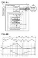
- FIG. 1A is a diagram illustrating a power conversion system including a power convertor according to an embodiment.
- the power conversion system 100 includes a power convertor 1, a power source 2, and a rotating electric machine 3.
- the power convertor 1 is interposed between the power source 2 and the rotating electric machine 3 to perform power conversion between the power source 2 and the rotating electric machine 3.
- the power convertor 1 functions as, for example, a motor controller to control the current through the rotating electric machine 3 so as to control the rotating electric machine 3.
- Examples of the power source 2 include, but are not limited to, direct-current (DC) power sources and alternating-current (AC) power sources such as fuel cells and power generators to convert natural energy of solar power or wind power into electric energy.
- Examples of the rotating electric machine 3 include motors with a stator and a rotor.
- Another possible example of the power source 2 is a power system.
- Another possible example of the rotating electric machine 3 is a power generator with a stator and a rotor.
- the power convertor 1 includes a power conversion unit 10, a current detector 11, and a controller 20 (which is an example of the controller).
- the power conversion unit 10 includes components such as a plurality of switching elements, and the controller 20 controls switching of the switching elements.
- the current detector 11 detects current flowing between the power conversion unit 10 and the rotating electric machine 3 (hereinafter referred to as output current). In the following description, voltage output from the power conversion unit 10 to the rotating electric machine 3 will be referred to as output voltage.
- the controller 20 controls the switching elements of the power conversion unit 10 to perform power conversion between the power source 2 and the rotating electric machine 3.
- the controller 20 includes a command generator 21, a PWM controller 22, and a frequency changer 23.
- the command generator 21 generates a control command to a control target.
- the control target include, but are not limited to, the rotation position of the rotating electric machine 3, the rotation speed of the rotating electric machine 3, the output current, and the output voltage.
- the command generator 21 generates an output voltage command serving as the control command based on, for example, the output current detected by the current detector 11.
- the PWM controller 22 Based on the control command generated by the command generator 21, the PWM controller 22 generates a drive signal (hereinafter referred to as PWM signal) for pulse width modulation (PWM) control of the switching elements of the power conversion unit 10. For example, the PWM controller 22 compares the output voltage command with a carrier signal to generate the PWM signal.
- PWM signal a drive signal for pulse width modulation
- the frequency changer 23 Based on a control deviation ⁇ cont with respect to the control target, the frequency changer 23 changes carrier frequency fc, which is used in PWM control performed by the PWM controller 22.
- a non-limiting example of the carrier frequency fc is the frequency of the carrier signal.
- the frequency changer 23 calculates a deviation (hereinafter referred to as current deviation) between the output current command generated by the command generator 21 and the output current detected by the current detector 11. Based on the current deviation, the frequency changer 23 changes the carrier frequency fc.
- the frequency changer 23 includes an outputter 51, an integrator 52, and a frequency determiner 53.
- the outputter 51 when the control deviation ⁇ cont is equal to or larger than the threshold TH1, the outputter 51 outputs a carrier-up value ⁇ up (which is an example of the first control value) to increase the carrier frequency fc.
- the outputter 51 When the control deviation ⁇ cont is equal to or smaller than the threshold TH2, the outputter 51 outputs a carrier-down value ⁇ down (which is an example of the second control value) to decrease the carrier frequency fc.
- the integrator 52 integrates the output from the outputter 51 and outputs an integral value Tcnt. Based on the integral value Tcnt, which is obtained by the integrator 52, the frequency determiner 53 determines the carrier frequency fc. The PWM controller 22 performs PWM control at the carrier frequency fc determined by the frequency determiner 53.
- the outputter 51 compares the control deviation ⁇ cont with the threshold TH1 and with the threshold TH2.
- the control deviation ⁇ cont gradually increases from timing t0 and becomes equal to or larger than the threshold TH1 between timings t3 and t5 in a carrier cycle Tc1.
- the outputter 51 repeatedly outputs the carrier-up value ⁇ up to cause the integral value Tcnt, which is obtained by the integrator 52, to gradually decrease.
- the control deviation ⁇ cont gradually decreases. Since the control deviation ⁇ cont is equal to or larger than the threshold TH2 from timing t7 to timing t9, the integral value Tcnt becomes the lower limit value Tmin.
- the PWM controller 22 changes the carrier signal Sc into a carrier signal of the frequency fc5 to perform PWM control.
- the control deviation ⁇ cont continuously decreases until timing t10.
- the control deviation ⁇ cont becomes equal to or smaller than the threshold TH2.
- the outputter 51 outputs the carrier-down value ⁇ down to increase the integral value Tcnt.
- the frequency determiner 53 determines the frequency fc4 (1/ Tc4 ) , which is one level lower than the frequency fc5, as the carrier frequency fc.
- the PWM controller 22 changes the carrier signal Sc into a carrier signal of the frequency fc4 to perform PWM control.
- the frequency determiner 53 similarly determines the carrier frequency fc based on the integral value Tcnt to set the carrier frequency fc so as to decrease the control deviation ⁇ cont.
- the carrier cycle Tc of the PWM control is shortened.
- the integral value Tcnt is used to determine the carrier frequency fc. This ensures that even if noise or other factors cause a detection error, the carrier frequency fc is adjusted more accurately.
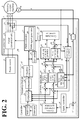
- FIG. 2 is a diagram illustrating an exemplary configuration of the power convertor 1 illustrated in FIG. 1A .
- the control deviation ⁇ cont is a control deviation of the output current.
- the power convertor 1 includes the power conversion unit 10, the current detector 11, and the controller 20.
- the power conversion unit 10 includes the plurality of switching elements to perform power conversion between the power source 2 and the rotating electric machine 3. Examples of the power source 2 include, but are not limited to, DC power sources and AC power sources.
- the power conversion unit 10 may be coupled to other devices and power source systems, instead of to the rotating electric machine 3.
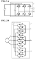
- FIGs. 3A and 3B are diagrams illustrating exemplary configurations of the power conversion unit 10.
- the power conversion unit 10 illustrated in FIG. 3A is an inverter circuit including a three-phase bridge circuit.
- the power conversion unit 10 illustrated in FIG. 3B is a matrix convertor circuit including bidirectional switches that respectively connect the phases (the R phase, the S phase, and the T phase) of the power source 2 to the phases (the U phase, the V phase, and the W phase) of the rotating electric machine 3. It is noted that the power conversion unit 10 should not be limited to the configurations illustrated in FIGs. 3A and 3B insofar as the power conversion unit 10 is capable of power conversion between the power source 2 and the rotating electric machine 3.
- Another possible embodiment of the power conversion unit 10 is a convertor circuit.
- the current detector 11 detects instantaneous values iu, iv, and iw of currents (hereinafter referred to as output currents iu, iv, and iw ) that respectively flow between the power conversion unit 10 and the U phase, the V phase, and the W phase of the rotating electric machine 3.
- the current detector 11 detects current using Hall elements, which are magneto-electric conversion elements.
- the controller 20 includes the command generator 21, the PWM controller 22, the frequency changer 23, a gain setter 24, an estimator 25, and a restrictor 26.
- the command generator 21 generates output voltage commands vu* vv* , and vw* in a predetermined calculation cycle Ts (hereinafter referred to as command calculation cycle Ts ).
- the command generator 21 includes a differentiator 30, subtractors 31, 35, and 36, a speed controller 32, a current command generator 33, coordinate convertors 34 and 45, a d -axis current controller 37, a q -axis current controller 38, a non-interference controller 39, adders 40, 41, and 44, an amplitude command generator 42, and a phase command generator 43.
- the differentiator 30 differentiates the rotation position, ⁇ (electrical angle), of the rotating electric machine 3 to obtain the rotation speed, ⁇ (electrical angular speed), of the rotating electric machine 3.
- the rotation position ⁇ of the rotating electric machine 3 is detected by a rotation position detector 4 (such as an encoder) or a similar device attached to the rotating electric machine 3.
- the subtractor 31 subtracts the rotation speed ⁇ from a speed command ⁇ *.
- the speed command ⁇ * is generated by a speed command generator or a similar device, not illustrated.
- the speed controller 32 generates a torque command T * to make the deviation (speed deviation) between the speed command ⁇ * and the rotation speed ⁇ zero.
- the current command generator 33 generates a d -axis current command id* and a q -axis current command iq* based on the torque command T*.
- the d -axis current command id* is a d -axis component in a d-q axis coordinate system.
- the q -axis current command iq* is a q -axis component in the d-q axis coordinate system.
- the d-q axis coordinate system is an orthogonal coordinate system that rotates in synchronism with the output frequency of AC voltage output from the power conversion unit 10.
- the d -axis component is a component on the axis parallel to the magnetic flux of the rotating electric machine 3 in the d-q axis coordinate system
- the q -axis component is a component on the q -axis, which is perpendicular to the d -axis, in the d-q axis coordinate system.
- the coordinate convertor 34 converts the output currents iu, iv, and iw into ⁇ components on two orthogonal axes of a fixed coordinate system to calculate a fixed coordinate current vector i ⁇ of the ⁇ axis coordinate system.
- the coordinate convertor 34 also uses the rotation position ⁇ to convert the fixed coordinate current vector i ⁇ into d-q components of the d-q axis coordinate system.
- the coordinate convertor 34 calculates the d -axis current id, which is a current component in the d -axis direction, and the q -axis current iq, which is a current component in the q -axis direction.
- the subtractor 35 subtracts the d -axis current id from the d -axis current command id*.
- the subtractor 36 subtracts the q -axis current iq from the q -axis current command iq*.
- the d -axis current controller 37 generates a d -axis voltage command vd1* to make the d -axis current deviation, ⁇ id, between the d -axis current command id* and the d -axis current id zero.
- the q -axis current controller 38 generates a q -axis voltage command vq1* to make the q -axis current deviation ⁇ iq between the q -axis current command iq* and the q -axis current iq* zero.
- the non-interference controller 39 compensates for interference between the d -axis and the q -axis and for induction voltage. Based on the d -axis current id, the q -axis current iq, the rotation speed ⁇ , and an induction voltage constant ⁇ , the non-interference controller 39 generates and outputs a d -axis voltage compensation value vdff and a q -axis voltage compensation value vqff.
- the non-interference controller 39 performs the calculation " id ⁇ ⁇ Ld + ⁇ " to obtain the q -axis voltage compensation value vqff, and performs the calculation "-iq ⁇ ⁇ Lq" to obtain the d -axis voltage compensation value vdff.
- Ld denotes a d -axis inductance value of the rotating electric machine 3
- Lq denotes a q -axis inductance value of the rotating electric machine 3.
- the adder 40 adds the d -axis voltage compensation value vdff to the d -axis voltage command vd1* so as to generate a d -axis voltage command vd*.
- the adder 41 adds the q -axis voltage compensation value vqff to the q -axis voltage command vq1* so as to generate a q -axis voltage command vq* .
- the amplitude command generator 42 calculates an amplitude command M based on the d -axis voltage command vd * and the q -axis voltage command vq*. For example, the amplitude command generator 42 obtains the amplitude command M by the calculation represented by the following Formula (1).
- the phase command generator 43 calculates an output phase command ⁇ a based on the d -axis voltage command vd * and the q -axis voltage command vq*. For example, the phase command generator 43 obtains the output phase command ⁇ a by the calculation represented by the following Formula (2).
- the adder 44 adds the rotation position ⁇ to the output phase command ⁇ a output from the phase command generator 43 so as to obtain a phase ⁇ v , and outputs the phase ⁇ v to the coordinate convertor 45.
- the coordinate convertor 45 generates the output voltage commands vu* , vv* , and vw* based on the amplitude command M and the phase ⁇ v .
- the PWM controller 22 includes a PWM signal generator 80.
- the PWM signal generator 80 generates a PWM signal based on the output voltage commands vu*, vv* , and vw* by the triangular wave comparison method or the space vector method. Then, the PWM signal generator 80 outputs the PWM signal to the power conversion unit 10.
- the switching elements constituting the power conversion unit 10 are controlled between ON and OFF, and three-phase AC power corresponding to the output voltage commands vu* , vv* , and vw* is output from the power conversion unit 10 to the rotating electric machine 3.
- the gain setter 24 adjusts a gain for feedback control of the control target in accordance with the carrier frequency fc.
- the command generator 21 performs feedback control of the control target using the gain adjusted by the gain setter 24.
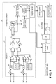
- FIG. 4 is a diagram illustrating the exemplary configuration of the frequency changer 23 and the gain setter 24.
- the outputter 51 includes subtractors 61 and 65 (which are examples of the difference calculator), absolute value calculators 62 and 66, comparers 63 and 67 (which are examples of the first comparer), comparers 64 and 68 (which are examples of the second comparer), a logical sum calculator 69, a logical product calculator 70, multipliers 71 and 72, and an adder 73.
- the subtractor 61 subtracts the d -axis current id from the d -axis current command id* to obtain a d -axis current deviation ⁇ id.
- the absolute value calculator 62 calculates an absolute value of the d -axis current deviation ⁇ id. When the absolute value of the d -axis current deviation ⁇ id is equal to or larger than a first d -axis threshold ⁇ Upd (which is an example of the first threshold), the comparer 63 outputs a d -axis carrier-up value Sud.
- the comparer 64 When the absolute value of the d -axis current deviation ⁇ id is equal to or smaller than a second d -axis threshold ⁇ Downd (which is an example of the second threshold), the comparer 64 outputs a d -axis carrier-down value Sdd.
- the subtractor 65 subtracts the q -axis current iq from the q -axis current command iq* to obtain a q -axis current deviation ⁇ iq.
- the absolute value calculator 66 calculates an absolute value of the q -axis current deviation ⁇ iq. When the absolute value of the q -axis current deviation ⁇ iq is equal to or larger than a first q -axis threshold ⁇ Upq (which is an example of the first threshold), the comparer 67 outputs a q -axis carrier-up value Suq.
- the comparer 68 When the absolute value of the q -axis current deviation ⁇ iq is equal to or smaller than a second q -axis threshold ⁇ Downq (which is an example of the second threshold), the comparer 68 outputs a q -axis carrier-down value Sdq.
- the logical sum calculator 69 calculates a logical sum of a result of the comparison by the comparer 63 and a result of the comparison by the comparer 67. When at least one of the d -axis carrier-up value Sud and the q -axis carrier-up value Suq is input, the logical sum calculator 69 outputs a carrier-up value Su.
- the multiplier 71 (which is an example of the first multiplier) multiplies the carrier-up value Su by a carrier-up gain Kup (which is an example of the first coefficient) and outputs the product as a carrier-up value ⁇ up.
- the logical product calculator 70 calculates a logical product of a result of the comparison by the comparer 64 and a result of the comparison by the comparer 68.
- the logical product calculator 70 outputs a carrier-down value Sd.
- the multiplier 72 (which is an example of the second multiplier) multiplies the carrier-down value Sd by a carrier down gain Kdown (which is an example of the second coefficient) and outputs the product as a carrier-down value ⁇ down.
- the adder 73 adds the product obtained by the multiplier 71 to the product obtained by the multiplier 72, and outputs the sum as a carrier change value to the integrator 52.
- the outputter 51 outputs the carrier-up value ⁇ up as a carrier change value.
- the outputter 51 When, for example, the absolute value of the d -axis current deviation ⁇ id is equal to or smaller than the second d -axis threshold ⁇ Downd and when the absolute value of the q -axis current deviation ⁇ iq is equal to or smaller than the second q -axis threshold ⁇ Downq, the outputter 51 outputs the carrier-down value ⁇ down as a carrier change value.
- the outputter 51 does not output a carrier change value but outputs, for example, a value of "0".
- the integrator 52 integrates the value output from the outputter 51 repeatedly in every command calculation cycle Ts.
- An integral value Tcnt which is a result of the integration by the integrator 52, is input into the frequency determiner 53 through a limiter 54.
- the limiter 54 limits the integral value Tcnt within the range between the upper limit value Tmax and the lower limit value Tmin.
- the limiter 54 when the integral value Tcnt exceeds the upper limit value Tmax, the limiter 54 outputs the upper limit value Tmax as the integral value Tcnt to replace the integral value Tcnt, which is obtained by the integrator 52, with the upper limit value Tmax.
- the limiter 54 When the integral value Tcnt is smaller than the lower limit value Tmin, the limiter 54 outputs the lower limit value Tmin as the integral value Tcnt to replace the integral value Tcnt, which is obtained by the integrator 52, with the lower limit value Tmin.
- the frequency determiner 53 determines the carrier frequency fc. For example, the frequency determiner 53 performs the calculation represented by the following Formula (3), that is, divides the command calculation frequency fs by the integral value Tcnt, so as to determine the carrier frequency fc. That is, the command calculation frequency fs is Tcnt times the carrier frequency fc.
- Formula (3) a formula for dividing the command calculation frequency fs by the integral value Tcnt. That is, the command calculation frequency fs is Tcnt times the carrier frequency fc.
- fs fc ⁇ n ( n is an integer of two or more).
- gc fs / Tcnt
- the frequency determiner 53 determines the carrier frequency fc by the calculation represented by Formula (3).
- the frequency determiner 53 sets the carrier frequency fc between 3 kHz and 15 kHz. For example, when the integral value Tcnt is "6", the frequency determiner 53 determines the carrier frequency fc as 5 kHz. When the integral value Tcnt is "2", the frequency determiner 53 determines the carrier frequency fc as 15 kHz.
- the frequency changer 23 includes a carrier division number register 55, a carrier frequency register 56, and a register setter 57.
- the carrier division number register 55 stores the integral value Tcnt, which is output from the limiter 54, as a carrier counter division value Div.
- the carrier frequency register 56 stores the carrier frequency fc as a carrier frequency setting value Cfc.
- the PWM controller 22 generates a carrier signal Sc of a carrier frequency fc that is based on the carrier counter setting value Ctc stored in the carrier counter register 78.
- the register setter 57 stores the obtained calculation cycle setting value Ctu in a calculation cycle counter register 79.
- the current deviations ⁇ id and ⁇ iq will be referred to as the current deviation ⁇ i.
- the command generator 21 includes a calculation cycle counter. In a command calculation cycle Ts that is based on the calculation cycle setting value Ctu , the command generator 21 detects the d -axis current id and the q -axis current iq from the output currents iu, iv, and iw , and calculates output voltage commands vu* , vv* , and vw* . For example, at the timing at which a calculation cycle counter value Ss is zero, the command generator 21 starts detecting the d -axis current id and the q -axis current iq.
- the frequency determiner 53 determines the carrier frequency fc repeatedly in every command calculation cycle Ts.
- the frequency determiner 53 determines the carrier frequency fc in such a manner that as the integral value Tcnt decreases in the order: 10 ⁇ 8 ⁇ 6 ⁇ 4 ⁇ 2, the carrier frequency fc increases in the order: 3 kHz ⁇ 3.75 kHz ⁇ 5 kHz ⁇ 7.5 kHz ⁇ 15 kHz.
- the frequency determiner 53 sets, in the carrier frequency register 56, the carrier counter setting value Ctc in accordance with the determined carrier frequency fc.
- the PWM controller 22 changes the carrier signal Sc into a carrier signal of 15 kHz based on the carrier counter setting value Ctc to perform PWM control.
- the frequency determiner 53 maintains the carrier frequency fc at 15 kHz at timing t13, which is a timing corresponding to a valley of the carrier signal Sc.
- the current deviation ⁇ i is equal to or smaller than the second threshold THi2.
- the frequency determiner 53 determines the carrier frequency fc in such a manner that as the integral value Tcnt increases in the order: 2 ⁇ 3 ⁇ 4, the carrier frequency fc decreases in the order: 15 kHz ⁇ 7.5 kHz ⁇ 5 kHz.
- the frequency determiner 53 sets the carrier counter setting value Ctc in accordance with the determined carrier frequency fc in the carrier frequency register 56.
- the PWM controller 22 changes the carrier signal Sc into a carrier signal of 5 kHz based on the carrier counter setting value Ctc to perform PWM control.
- the frequency determiner 53 similarly determines the carrier frequency fc based on the integral value Tcnt to cause the current deviation ⁇ i to decrease.
- the carrier cycle Tc of the PWM control is shortened. This configuration enhances control responsiveness.
- the integral value Tcnt is used to determine the carrier frequency fc. This ensures that even if noise or other factors cause a detection error or an estimation error, the carrier frequency fc is adjusted more accurately. Further, as the calculation cycle Ts becomes shorter with respect to the carrier cycle Tc, there is less of an influence of noise or other factors.
- the carrier-up gain Kup and the carrier down gain Kdown are parameters settable by an input device not illustrated. Adjusting these parameters makes control responsiveness more accurate in accordance with the environment in which the power convertor 1 is installed.
- the carrier-up gain Kup is larger than the carrier down gain Kdown. This configuration increases the carrier frequency fc more expeditiously.
- the gain setter 24 includes a delayer 82, a change detector 83, and a control gain setter 84.
- the delayer 82 delays and outputs the carrier counter setting value Ctc, which is set in the carrier counter register 78.
- the change detector 83 determines that the carrier counter setting value Ctc has changed.
- the control gain setter 84 selects a current control gain and a speed control gain in accordance with the carrier frequency fc determined by the frequency determiner 53.
- the control gain setter 84 sets the selected current control gain in the d -axis current controller 37 and the q -axis current controller 38, and sets the selected speed control gain in the speed controller 32. This configuration ensures that as the carrier frequency fc increases, the current control gain and the speed control gain increase.
- the control gain setter 84 includes a control gain setting table that correlates, for example, the carrier frequency fc to the current control gain and the speed control gain. Based on the control gain setting table, the control gain setter 84 selects the current control gain and the speed control gain in accordance with the carrier frequency fc.
- the controller 20 includes the gain setter 24.
- the gain setter 24 sets, in the command generator 21, a control gain in accordance with the carrier frequency fc. This configuration enhances control responsiveness appropriately in accordance with the carrier frequency fc.
- the estimator 25 estimates a load that is applied on the power conversion unit 10, for example, per unit time. Based on the current output from the power conversion unit 10 and the carrier frequency fc, the estimator 25 estimates the load on the power conversion unit 10. A non-limiting example of the load on the power conversion unit 10 is power consumed by the switching elements constituting the power conversion unit 10.
- the estimator 25 may determine the current output from the power conversion unit 10 based on the output current detected by the current detector 11 or may determine the current output from the power conversion unit 10 based on the torque command T * or the q -axis current command iq *.
- the restrictor 26 restricts the change made by the frequency changer 23 to the carrier frequency fc.
- the load on the power conversion unit 10 is determined by the estimator 25.
- the restrictor 26 restricts the change made by the frequency changer 23 to the carrier frequency fc.
- the restrictor 26 stops the operation of the frequency changer 23. In this manner, the restrictor 26 restricts the change made by the frequency changer 23 to the carrier frequency fc.
- a control value is a value at which the power conversion unit 10 is kept from running out of order.
- the restrictor 26 is also capable of limiting the change made by the frequency changer 23 to the carrier frequency fc within a range in accordance with the load on the power conversion unit 10.
- the restrictor 26 may decrease the carrier frequency fc to equal to or lower than a predetermined value (for example, 1 / 2 of the upper limit value of the carrier frequency fc ). This configuration minimizes the load applied on the power conversion unit 10.
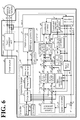
- FIG. 6 is a diagram illustrating another exemplary configuration of the power convertor 1 illustrated in FIG. 1A .
- the control deviation ⁇ cont is a control deviation of the output current and a control deviation of the rotation position.
- the power convertor 1 illustrated in FIG. 6 is an encoder-less power convertor.
- a non-limiting example of a rotating electric machine 3 illustrated in FIG. 6 is a rotating electric machine with magnetic saliency, such as an interior permanent magnet synchronous motor and a synchronous reactance motor.
- the controller 20 of the power convertor 1 illustrated in FIG. 6 uses a difference (magnetic saliency) between inductance values of the magnetic flux axis ( d -axis) and the axis ( q -axis) perpendicular to the magnetic flux axis to estimate the magnetic pole position (electrical angle) of the rotor of the rotating electric machine 3.
- the controller 20 includes a high-frequency generator 90, an adder 91, a band pass filter (BPF) 92, a 45-degree coordinate convertor 93, a speed-and-magnetic-pole-position estimator 94, and a notch filter 95.
- BPF band pass filter
- the high-frequency generator 90 generates and outputs a high-frequency voltage signal vinj of a frequency ⁇ inj, which is higher than the frequency, ⁇ , of the output voltage.
- the adder 91 adds the high-frequency voltage signal vinj, which is output from the high-frequency generator 90, to a d -axis voltage command vd * and outputs the sum.
- the d -axis voltage command vd * is a voltage command of a ⁇ -axis (imaginary d -axis), which is a magnetic flux axis of the control.
- the high-frequency voltage signal vinj is superimposed on the d -axis voltage command vd *, and thus a high-frequency current component flows through the rotating electric machine 3.
- the band pass filter 92 extracts a component in the band of the frequency ⁇ inj so as to extract the high-frequency current component flowing through the rotating electric machine 3. Then, the band pass filter 92 outputs the high-frequency current component as a d -axis current idbpf and as a q -axis current iqbpf.
- the 45-degree coordinate convertor 93 converts the d -axis current idbpf and the q -axis current iqbpf into currents in a dm-qm coordinate system, which is obtained by turning the d-q coordinate system by 45 degrees. Then, the 45-degree coordinate convertor 93 outputs the converted currents as a d -axis current idm and a q -axis current iqm.
- the speed-and-magnetic-pole-position estimator 94 calculates, repeatedly in every command calculation cycle Ts, an estimation deviation of the rotation position (electrical angle) (hereinafter referred to as estimation position deviation ⁇ ⁇ ), an estimation value of the rotation speed ⁇ (hereinafter referred to as estimation speed ⁇ ⁇ ), and an estimation value of the rotation position (magnetic pole position) (hereinafter referred to as estimation position ⁇ ⁇ ).
- the speed-and-magnetic-pole-position estimator 94 adjusts the estimation speed ⁇ ⁇ and the estimation position ⁇ ⁇ to make the amplitude of the d -axis current idm equal to the amplitude of the q -axis current iqm, thereby calculating the estimation speed ⁇ ⁇ and the estimation position ⁇ ⁇ .
- the speed-and-magnetic-pole-position estimator 94 calculates the amplitude of the d -axis current idm and the amplitude of the q -axis current iqm.
- the speed-and-magnetic-pole-position estimator 94 performs proportional integration (PI) control of a deviation between the amplitude of the d -axis current idm and the amplitude of the q -axis current iqm using a PI controller, and calculates such an estimation speed ⁇ ⁇ that makes the output of the PI controller zero.
- the speed-and-magnetic-pole-position estimator 94 also integrates the estimation speed ⁇ ⁇ to obtain the estimation position ⁇ ⁇ .
- the speed-and-magnetic-pole-position estimator 94 obtains the estimation position deviation ⁇ ⁇ by the calculation represented by the following Formula (4).
- L d denotes a d -axis inductance value of the rotating electric machine 3
- L q denotes a q -axis inductance value of the rotating electric machine 3
- vinj denotes the amplitude of the high-frequency voltage signal vinj.
- the speed-and-magnetic-pole-position estimator 94 may calculate the estimation position deviation ⁇ ⁇ , the estimation speed ⁇ ⁇ , and the estimation position ⁇ ⁇ using an induction voltage observer, for example. In this case, there is no need for providing the high-frequency generator 90, the adder 91, the band pass filter 92, and the 45-degree coordinate convertor 93. It is possible to provide a speed deviation calculator to calculate a deviation between the speed command ⁇ * and the estimation speed ⁇ ⁇ as the estimation position deviation ⁇ ⁇ .
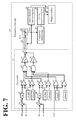
- FIG. 7 is a diagram illustrating an exemplary configuration of the frequency changer 23 illustrated in FIG. 6 .
- the frequency changer 23 illustrated in FIG. 7 is different from the frequency changer 23 illustrated in FIG. 4 in that the estimation position deviation ⁇ ⁇ is taken into consideration as the control deviation in addition to the current deviation when the carrier frequency fc is changed.
- identical components and functions of the frequency changers 23 illustrated in FIGs. 4 and 7 will be denoted with the same reference numerals and will not be elaborated here.
- the frequency changer 23 illustrated in FIG. 7 includes a comparer 74 (which is an example of the first comparer) and a comparer 75 (which is an example of the second comparer).
- a comparer 74 which is an example of the first comparer
- a comparer 75 which is an example of the second comparer.
- the logical sum calculator 69 calculates a logical sum of the result of the comparison performed by the comparer 63, the result of the comparison performed by the comparer 67, and the result of the comparison by the comparer 74.
- the logical sum calculator 69 outputs the carrier-up value Su.
- the multiplier 71 multiplies the carrier-up value Su by the carrier-up gain Kup and outputs the product as the carrier-up value ⁇ up
- the logical product calculator 70 calculates a logical product of the result of the comparison performed by the comparer 64, the result of the comparison performed by the comparer 68, and the result of the comparison by the comparer 75.
- the logical product calculator 70 outputs the carrier-down value Sd.
- the multiplier 72 multiplies the carrier-down value Sd by the carrier down gain Kdown and outputs the product as the carrier-down value ⁇ down.
- This configuration ensures changing the carrier frequency fc based on the current deviation ⁇ i and the estimation position deviation ⁇ ⁇ .
- the carrier cycle Tc is shortened, as described above.
- the estimation position deviation ⁇ ⁇ increases, the carrier cycle Tc is shortened.
- the integral value Tcnt is used to determine the carrier frequency fc. This ensures that even if noise or other factors cause a detection error, the carrier frequency fc is adjusted more accurately.
- the current deviation ⁇ i and the estimation position deviation ⁇ ⁇ are taken as examples of the control deviation.
- Other possible examples of the control deviation include a control deviation of the output voltage and a control deviation of the rotation speed.
- the frequency changer 23 may determine the carrier frequency fc based on, for example, a deviation (speed deviation) between the rotation speed ⁇ and the speed command ⁇ * illustrated in FIG. 2 .
- the frequency changer 23 determines the carrier frequency fc.
- the controller 20 includes a microcomputer and various circuits.
- the microcomputer includes a central processing unit (CPU), a read only memory (ROM), a random access memory (RAM), and input-output ports.
- the CPU of the microcomputer reads a program stored in the ROM and executes the program, and thus functions as the command generator 21, the PWM controller 22, the frequency changer 23, the gain setter 24, the estimator 25, and the restrictor 26.
- At least one or all of the command generator 21, the PWM controller 22, the frequency changer 23, the gain setter 24, the estimator 25, and the restrictor 26 may be made up of hardware such as an application specific integrated circuit (ASIC) and a field programmable gate array (FPGA).
- ASIC application specific integrated circuit
- FPGA field programmable gate array
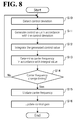
- FIG. 8 is a flowchart of an exemplary flow of control processing performed by the controller 20.
- the controller 20 repeatedly performs the control processing illustrated in FIG. 8 .
- Steps S10 to S13 are processing performed by the frequency changer 23
- steps S14 and S15 are processing performed by the PWM controller 22
- step S16 is processing by the gain setter 24.
- the outputter 51 of the frequency changer 23 detects the control deviation ⁇ cont (step S10) and generates a control value in accordance with the control deviation ⁇ cont (step S11).
- the control deviation ⁇ cont include, but are not limited to, the current deviation, the position deviation (phase deviation), and the speed deviation.
- the control deviation may be based on a detection value or an estimation value.
- the integrator 52 of the frequency changer 23 adds up control values output from the outputter 51 and thus integrates the output from the outputter 51 (step S12).
- the frequency determiner 53 of the frequency changer 23 determines the carrier frequency fc in accordance with the integral value Tcnt, which is obtained by the integrator 52, for example (step S13).
- the PWM controller 22 makes a determination as to whether a timing for changing the carrier frequency fc has come (step S14). For example, at a timing corresponding to a valley of the carrier signal Sc, the PWM controller 22 determines that the timing is a timing for changing the carrier frequency fc.
- the PWM controller 22 updates the carrier frequency fc of the carrier signal Sc using the carrier frequency fc determined by the frequency determiner 53 at step S 13 (step S 15). It is noted that the processing at steps S14 and S15 is implemented by the PWM controller 22 functioning as a frequency changer. It is also possible for the frequency changer 23 to perform the processing at steps S14 and S15.
- the gain setter 24 updates the control gain (step S16).
- the gain setter 24 determines the current control gain and the speed control gain as control gains in accordance with the carrier frequency fc updated at step S15.
- the gain setter 24 sets the determined current control gain in the d -axis current controller 37 and the q -axis current controller 38, and sets the determined speed control gain in the speed controller 32.
- the frequency changer 23 When the timing is not a timing for changing the carrier frequency fc (No at step S14), the frequency changer 23 performs the processing at steps S10 to S13.
- the processing at steps S10 to S13 is repeatedly performed in every command calculation cycle Ts.
- the carrier-up value ⁇ up or the carrier-down value ⁇ down is generated in one command calculation cycle Ts.
- the carrier-up value ⁇ up and the carrier-down value ⁇ down may be generated at multiple stages. For example, when the control deviation ⁇ cont is equal to or larger than the threshold TH1 , the outputter 51 may increase the carrier-up value ⁇ up to the positive side (or negative side) as the control deviation ⁇ cont increases. When the control deviation ⁇ cont is equal to or smaller than the threshold TH2 , the outputter 51 may increase the carrier-up value ⁇ up to the negative side (or positive side) as the control deviation ⁇ cont decreases.
- the command calculation frequency fs is Tcnt times the carrier frequency fc. This configuration, however, should not be construed in a limiting sense; it suffices that the command calculation frequency fs is higher than the carrier frequency fc. Thus, even if noise or other factors cause a detection error, the carrier frequency fc is adjusted more accurately.
- the output voltage is a three-phase AC voltage. This configuration, however, should not be construed in a limiting sense. Another possible embodiment is that the output voltage is a single-phase AC voltage.
- the carrier frequency fc of the PWM controller 22 is changed at a timing corresponding to a valley of the carrier signal Sc.
- the PWM controller 22 and the frequency changer 23 change the carrier frequency fc of the PWM controller 22 at a timing corresponding to a valley of the carrier signal Sc.
- the PWM controller 22 and the frequency changer 23 change the carrier frequency fc of the PWM controller 22 at timings corresponding to a peak and a peak of the carrier signal Sc.
- the PWM controller 22 and the frequency changer 23 regard peaks and valleys of the carrier signal Sc as count timings, and change the carrier frequency fc of the PWM controller 22 at every m -th counting ( m is an integer of three or more).
- the d -axis current deviation ⁇ id and the q -axis current deviation ⁇ iq are respectively compared with the first threshold and the second threshold.
- This configuration should not be construed as limiting comparison subjects.
- the outputter 51 calculates root mean squares of the d -axis current deviation ⁇ id and the q -axis current deviation ⁇ iq, and compares the root mean squares respectively with the first threshold and the second threshold.
- Another possible embodiment is to compare the q -axis current deviation ⁇ iq with the first threshold and the second threshold.
- the carrier-up value ⁇ up is a negative value
- the carrier-down value ⁇ down is a positive value
- the carrier-up value ⁇ up is a positive value
- the carrier-down value ⁇ down is a negative value
- the upper limit value Tmax and the lower limit value Tmin are negative values where Tmax ⁇ Tmin.
Abstract
A power convertor includes a power conversion unit, a PWM controller, and a frequency changer. The power conversion unit includes a plurality of switching elements. The PWM controller is configured to perform PWM control of the plurality of switching elements. The frequency changer is configured to change a carrier frequency in the PWM control. The frequency changer includes an outputter, an integrator, and a frequency determiner. The outputter is configured to output a control value in accordance with a control deviation with respect to a control target. The integrator is configured to integrate the control value output from the outputter. The frequency determiner is configured to determine the carrier frequency based on an integral value obtained by the integrator.
Description
- The present invention relates to a power convertor, a controller, and a method for changing a carrier frequency.
- Examples of PWM-control power convertors include inverters, convertors, and matrix convertors.
- Japanese Unexamined Patent Application Publication No.
2001-37248 - The contents of Japanese Unexamined Patent Application Publication No.
2001-37248 - In this conventional power converter, however, noise or other factors may cause a detection error in detection of the control deviation, to the detriment of accurate adjustment of the carrier frequency.
- An aspect of the embodiment has been made in view of the above-described circumstances. It is an object of the present disclosure to provide a power convertor, a controller, and a method for changing a carrier frequency that enhance control responsiveness.
- According to one aspect of the present disclosure, a power convertor includes a power conversion unit, a PWM controller, and a frequency changer. The power conversion unit includes a plurality of switching elements. The PWM controller is configured to perform PWM control of the plurality of switching elements. The frequency changer is configured to change a carrier frequency in the PWM control. The frequency changer includes an outputter, an integrator, and a frequency determiner. The outputter is configured to output a control value in accordance with a control deviation with respect to a control target. The integrator is configured to integrate the control value output from the outputter. The frequency determiner is configured to determine the carrier frequency based on an integral value obtained by the integrator.
- The aspect of the embodiment provides a power convertor, a controller, and a method for changing a carrier frequency that enhance control responsiveness.
- A more complete appreciation of the present disclosure and many of the attendant advantages thereof will be readily obtained as the same becomes better understood by reference to the following detailed description when considered in connection with the accompanying drawings, wherein:
-
FIG. 1A is a diagram illustrating a power conversion system including a power convertor according to an embodiment; -
FIG. 1B is a graph of a control deviation, an integral value, and a carrier frequency in relation to each other; -
FIG. 2 is a diagram illustrating an exemplary configuration of the power convertor illustrated inFIG. 1A ; -
FIG. 3A is a diagram illustrating an exemplary configuration of a power conversion unit; -
FIG. 3B is a diagram illustrating another exemplary configuration of a power conversion unit; -
FIG. 4 is a diagram illustrating an exemplary configuration of a frequency changer and a gain setter illustrated inFIG. 2 ; -
FIG. 5 is a graph of a carrier cycle counter, a calculation cycle counter, a command calculation cycle, a current deviation, and an integral value in relation to each other; -
FIG. 6 is a diagram illustrating another exemplary configuration of the power convertor illustrated inFIG. 1A ; -
FIG. 7 is a diagram illustrating an exemplary configuration of the frequency changer illustrated inFIG. 6 ; and -
FIG. 8 is a flowchart of an exemplary flow of control processing performed by a controller. - A power convertor, a controller, and a method for changing a carrier frequency according to embodiments will be described in detail below with reference to the accompanying drawings. The following embodiments are provided for exemplary purposes only and are not intended to limit the present disclosure.
-
FIG. 1A is a diagram illustrating a power conversion system including a power convertor according to an embodiment. As illustrated inFIG. 1A , thepower conversion system 100 according to this embodiment includes apower convertor 1, apower source 2, and a rotatingelectric machine 3. Thepower convertor 1 is interposed between thepower source 2 and the rotatingelectric machine 3 to perform power conversion between thepower source 2 and the rotatingelectric machine 3. Thepower convertor 1 functions as, for example, a motor controller to control the current through the rotatingelectric machine 3 so as to control the rotatingelectric machine 3. - Examples of the
power source 2 include, but are not limited to, direct-current (DC) power sources and alternating-current (AC) power sources such as fuel cells and power generators to convert natural energy of solar power or wind power into electric energy. Examples of the rotatingelectric machine 3 include motors with a stator and a rotor. Another possible example of thepower source 2 is a power system. Another possible example of the rotatingelectric machine 3 is a power generator with a stator and a rotor. - The
power convertor 1 includes apower conversion unit 10, acurrent detector 11, and a controller 20 (which is an example of the controller). Thepower conversion unit 10 includes components such as a plurality of switching elements, and thecontroller 20 controls switching of the switching elements. Thecurrent detector 11 detects current flowing between thepower conversion unit 10 and the rotating electric machine 3 (hereinafter referred to as output current). In the following description, voltage output from thepower conversion unit 10 to the rotatingelectric machine 3 will be referred to as output voltage. - The
controller 20 controls the switching elements of thepower conversion unit 10 to perform power conversion between thepower source 2 and the rotatingelectric machine 3. Thecontroller 20 includes acommand generator 21, aPWM controller 22, and afrequency changer 23. - The
command generator 21 generates a control command to a control target. Examples of the control target include, but are not limited to, the rotation position of the rotatingelectric machine 3, the rotation speed of the rotatingelectric machine 3, the output current, and the output voltage. For example, thecommand generator 21 generates an output voltage command serving as the control command based on, for example, the output current detected by thecurrent detector 11. - Based on the control command generated by the
command generator 21, thePWM controller 22 generates a drive signal (hereinafter referred to as PWM signal) for pulse width modulation (PWM) control of the switching elements of thepower conversion unit 10. For example, thePWM controller 22 compares the output voltage command with a carrier signal to generate the PWM signal. - Based on a control deviation Δcont with respect to the control target, the
frequency changer 23 changes carrier frequency fc, which is used in PWM control performed by thePWM controller 22. A non-limiting example of the carrier frequency fc is the frequency of the carrier signal. For example, thefrequency changer 23 calculates a deviation (hereinafter referred to as current deviation) between the output current command generated by thecommand generator 21 and the output current detected by thecurrent detector 11. Based on the current deviation, thefrequency changer 23 changes the carrier frequency fc. - The
frequency changer 23 includes anoutputter 51, anintegrator 52, and afrequency determiner 53. Theoutputter 51 outputs a control value in accordance with the control deviation Δcont. For example, in a cycle of Ts, which is shorter than carrier cycle Tc (= 1/fc), theoutputter 51 compares the control deviation Δcont with a threshold TH1 (which is an example of the first threshold) and with a threshold TH2 (which is an example of the second threshold). - For example, when the control deviation Δcont is equal to or larger than the threshold TH1, the
outputter 51 outputs a carrier-up value Δup (which is an example of the first control value) to increase the carrier frequency fc. When the control deviation Δcont is equal to or smaller than the threshold TH2, theoutputter 51 outputs a carrier-down value Δdown (which is an example of the second control value) to decrease the carrier frequency fc. - The
integrator 52 integrates the output from theoutputter 51 and outputs an integral value Tcnt. Based on the integral value Tcnt, which is obtained by theintegrator 52, thefrequency determiner 53 determines the carrier frequency fc. ThePWM controller 22 performs PWM control at the carrier frequency fc determined by thefrequency determiner 53. -
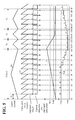
FIG. 1B is a graph of the control deviation Δcont, the integral value Tcnt, and the carrier frequency fc in relation to each other. Assume that at timing t0, Tcnt = Tmax and fc = 1 / Tc1. Assume that from timing t0, the control deviation Δcont gradually increases, and that the carrier-up value Δup is a negative value, and the carrier-down value Δdown is a positive value. Assume that the integral value Tcnt is restricted within the range between an upper limit value Tmax and a lower limit value Tmin. - In the cycle Ts, which is shorter than the carrier cycle Tc, the
outputter 51 compares the control deviation Δcont with the threshold TH1 and with the threshold TH2. In the embodiment illustrated inFIG. 1B , the control deviation Δcont gradually increases from timing t0 and becomes equal to or larger than the threshold TH1 between timings t3 and t5 in a carrier cycle Tc1. In view of this, between timings t3 and t5, theoutputter 51 repeatedly outputs the carrier-up value Δup to cause the integral value Tcnt, which is obtained by theintegrator 52, to gradually decrease. - The
frequency determiner 53 determines the carrier frequency fc in the cycle Ts, for example. Up to timing t5, the carrier-up value Δup has been output three times consecutively, and thus thefrequency determiner 53 determines a frequency fc4 (= 1/Tc4), which is three levels higher than the frequency fc, as the carrier frequency fc. At a timing (namely, timing t6) corresponding to a valley of the carrier signal, thePWM controller 22 changes the carrier signal Sc into a carrier signal of the frequency fc4 to perform PWM control. - After the carrier signal Sc has been changed into the carrier signal of the frequency fc4 at timing t6, the control deviation Δcont gradually decreases. Since the control deviation Δcont is equal to or larger than the threshold TH2 from timing t7 to timing t9, the integral value Tcnt becomes the lower limit value Tmin. In view of this, the
frequency determiner 53 determines a frequency fc5 (= 1/Tc5), which is one level higher than the frequency fc4, as the carrier frequency fc. At a timing (namely, timing t9) corresponding to a valley of the carrier signal, thePWM controller 22 changes the carrier signal Sc into a carrier signal of the frequency fc5 to perform PWM control. - Even after the carrier signal Sc has been changed into the carrier signal of the frequency fc5 at timing t9, the control deviation Δcont continuously decreases until timing t10. Around timing t10, the control deviation Δcont becomes equal to or smaller than the threshold TH2. In view of this, the
outputter 51 outputs the carrier-down value Δdown to increase the integral value Tcnt. Thefrequency determiner 53 determines the frequency fc4 (1/Tc4), which is one level lower than the frequency fc5, as the carrier frequency fc. At a timing (namely, timing t11) corresponding to a valley of the carrier signal, thePWM controller 22 changes the carrier signal Sc into a carrier signal of the frequency fc4 to perform PWM control. - From then on, the
frequency determiner 53 similarly determines the carrier frequency fc based on the integral value Tcnt to set the carrier frequency fc so as to decrease the control deviation Δcont. Thus, as the control deviation increases, the carrier cycle Tc of the PWM control is shortened. This configuration enhances control responsiveness. Also in this configuration, the integral value Tcnt is used to determine the carrier frequency fc. This ensures that even if noise or other factors cause a detection error, the carrier frequency fc is adjusted more accurately. - The
power convertor 1 according to this embodiment will now be described in more detail.FIG. 2 is a diagram illustrating an exemplary configuration of thepower convertor 1 illustrated inFIG. 1A . In the embodiment illustrated inFIG. 2 , the control deviation Δcont is a control deviation of the output current. - As illustrated in
FIG. 2 , thepower convertor 1 includes thepower conversion unit 10, thecurrent detector 11, and thecontroller 20. Thepower conversion unit 10 includes the plurality of switching elements to perform power conversion between thepower source 2 and the rotatingelectric machine 3. Examples of thepower source 2 include, but are not limited to, DC power sources and AC power sources. Thepower conversion unit 10 may be coupled to other devices and power source systems, instead of to the rotatingelectric machine 3. -
FIGs. 3A and 3B are diagrams illustrating exemplary configurations of thepower conversion unit 10. Thepower conversion unit 10 illustrated inFIG. 3A is an inverter circuit including a three-phase bridge circuit. Thepower conversion unit 10 illustrated inFIG. 3B is a matrix convertor circuit including bidirectional switches that respectively connect the phases (the R phase, the S phase, and the T phase) of thepower source 2 to the phases (the U phase, the V phase, and the W phase) of the rotatingelectric machine 3. It is noted that thepower conversion unit 10 should not be limited to the configurations illustrated inFIGs. 3A and 3B insofar as thepower conversion unit 10 is capable of power conversion between thepower source 2 and the rotatingelectric machine 3. Another possible embodiment of thepower conversion unit 10 is a convertor circuit. - Referring back to
FIG. 2 , thepower convertor 1 will be further described. As illustrated inFIG. 2 , thecurrent detector 11 detects instantaneous values iu, iv, and iw of currents (hereinafter referred to as output currents iu, iv, and iw) that respectively flow between thepower conversion unit 10 and the U phase, the V phase, and the W phase of the rotatingelectric machine 3. Thecurrent detector 11 detects current using Hall elements, which are magneto-electric conversion elements. - The
controller 20 includes thecommand generator 21, thePWM controller 22, thefrequency changer 23, again setter 24, anestimator 25, and arestrictor 26. Thecommand generator 21 generates output voltage commands vu* vv*, and vw* in a predetermined calculation cycle Ts (hereinafter referred to as command calculation cycle Ts). ThePWM controller 22 generates a PWM signal in every carrier cycle Tc (= 1/fc) by a carrier comparison method or a space vector method. Based on the PWM signal, thePWM controller 22 controls the switching elements of thepower conversion unit 10. For example, thePWM controller 22 compares the output voltage commands vu* vv*, and vw* with the carrier signal Sc to generate the PWM signal. - The
command generator 21 includes adifferentiator 30,subtractors speed controller 32, acurrent command generator 33, coordinateconvertors current controller 37, a q-axiscurrent controller 38, anon-interference controller 39,adders amplitude command generator 42, and aphase command generator 43. - The
differentiator 30 differentiates the rotation position, θ (electrical angle), of the rotatingelectric machine 3 to obtain the rotation speed, ω (electrical angular speed), of the rotatingelectric machine 3. The rotation position θ of the rotatingelectric machine 3 is detected by a rotation position detector 4 (such as an encoder) or a similar device attached to the rotatingelectric machine 3. Thesubtractor 31 subtracts the rotation speed ω from a speed command ω*. The speed command ω* is generated by a speed command generator or a similar device, not illustrated. For example, thespeed controller 32 generates a torque command T* to make the deviation (speed deviation) between the speed command ω* and the rotation speed ω zero. - The
current command generator 33 generates a d-axis current command id* and a q-axis current command iq* based on the torque command T*. The d-axis current command id* is a d-axis component in a d-q axis coordinate system. The q-axis current command iq* is a q-axis component in the d-q axis coordinate system. The d-q axis coordinate system is an orthogonal coordinate system that rotates in synchronism with the output frequency of AC voltage output from thepower conversion unit 10. The d-axis component is a component on the axis parallel to the magnetic flux of the rotatingelectric machine 3 in the d-q axis coordinate system, and the q-axis component is a component on the q-axis, which is perpendicular to the d-axis, in the d-q axis coordinate system. - The coordinate
convertor 34 converts the output currents iu, iv, and iw into αβ components on two orthogonal axes of a fixed coordinate system to calculate a fixed coordinate current vector iαβ of the αβ axis coordinate system. The coordinateconvertor 34 also uses the rotation position θ to convert the fixed coordinate current vector iαβ into d-q components of the d-q axis coordinate system. Thus, the coordinateconvertor 34 calculates the d-axis current id, which is a current component in the d-axis direction, and the q-axis current iq, which is a current component in the q-axis direction. - The
subtractor 35 subtracts the d-axis current id from the d-axis current command id*. Thesubtractor 36 subtracts the q-axis current iq from the q-axis current command iq*. The d-axiscurrent controller 37 generates a d-axis voltage command vd1* to make the d-axis current deviation, Δid, between the d-axis current command id* and the d-axis current id zero. The q-axiscurrent controller 38 generates a q-axis voltage command vq1* to make the q-axis current deviation Δiq between the q-axis current command iq* and the q-axis current iq* zero. - The
non-interference controller 39 compensates for interference between the d-axis and the q-axis and for induction voltage. Based on the d-axis current id, the q-axis current iq, the rotation speed ω, and an induction voltage constant φ, thenon-interference controller 39 generates and outputs a d-axis voltage compensation value vdff and a q-axis voltage compensation value vqff. For example, thenon-interference controller 39 performs the calculation "id × ωLd + ωφ" to obtain the q-axis voltage compensation value vqff, and performs the calculation "-iq × ωLq" to obtain the d-axis voltage compensation value vdff. In the above-described calculations, Ld denotes a d-axis inductance value of the rotatingelectric machine 3, and Lq denotes a q-axis inductance value of the rotatingelectric machine 3. In cases where a power system or other device than the rotatingelectric machine 3 is coupled to thepower conversion unit 10, there is no need for providing thenon-interference controller 39. - The
adder 40 adds the d-axis voltage compensation value vdff to the d-axis voltage command vd1* so as to generate a d-axis voltage command vd*. Theadder 41 adds the q-axis voltage compensation value vqff to the q-axis voltage command vq1* so as to generate a q-axis voltage command vq*. - The
amplitude command generator 42 calculates an amplitude command M based on the d-axis voltage command vd* and the q-axis voltage command vq*. For example, theamplitude command generator 42 obtains the amplitude command M by the calculation represented by the following Formula (1). Thephase command generator 43 calculates an output phase command θa based on the d-axis voltage command vd* and the q-axis voltage command vq*. For example, thephase command generator 43 obtains the output phase command θa by the calculation represented by the following Formula (2). Theadder 44 adds the rotation position θ to the output phase command θa output from thephase command generator 43 so as to obtain a phase θv, and outputs the phase θv to the coordinateconvertor 45.

- The coordinate
convertor 45 generates the output voltage commands vu*, vv*, and vw* based on the amplitude command M and the phase θv. For example, the coordinateconverter 45 may perform the calculations "vu* = M × sin(θv)", "vv* = M × sin(θv - 2/3π)", and "vw* = M × sin(θv - 4/3π)" to generate the output voltage commands vu*, vv*, and vw*. - The
PWM controller 22 includes aPWM signal generator 80. ThePWM signal generator 80 generates a PWM signal based on the output voltage commands vu*, vv*, and vw* by the triangular wave comparison method or the space vector method. Then, thePWM signal generator 80 outputs the PWM signal to thepower conversion unit 10. Thus, the switching elements constituting thepower conversion unit 10 are controlled between ON and OFF, and three-phase AC power corresponding to the output voltage commands vu*, vv*, and vw* is output from thepower conversion unit 10 to the rotatingelectric machine 3. - The
frequency changer 23 repeatedly determines the carrier frequency fc for PWM control in every command calculation cycle Ts (= 1/fs). For example, at a timing corresponding to a valley of the carrier signal Sc, thefrequency changer 23 changes the carrier frequency fc of thePWM controller 22. - The
gain setter 24 adjusts a gain for feedback control of the control target in accordance with the carrier frequency fc. Thecommand generator 21 performs feedback control of the control target using the gain adjusted by thegain setter 24. - An exemplary configuration of the
frequency changer 23 and thegain setter 24 will now be described.FIG. 4 is a diagram illustrating the exemplary configuration of thefrequency changer 23 and thegain setter 24. As illustrated inFIG. 4 , theoutputter 51 includessubtractors 61 and 65 (which are examples of the difference calculator),absolute value calculators comparers 64 and 68 (which are examples of the second comparer), alogical sum calculator 69, alogical product calculator 70,multipliers adder 73. - The
subtractor 61 subtracts the d-axis current id from the d-axis current command id* to obtain a d-axis current deviation Δid. Theabsolute value calculator 62 calculates an absolute value of the d-axis current deviation Δid. When the absolute value of the d-axis current deviation Δid is equal to or larger than a first d-axis threshold ΔUpd (which is an example of the first threshold), thecomparer 63 outputs a d-axis carrier-up value Sud. When the absolute value of the d-axis current deviation Δid is equal to or smaller than a second d-axis threshold ΔDownd (which is an example of the second threshold), thecomparer 64 outputs a d-axis carrier-down value Sdd. - The
subtractor 65 subtracts the q-axis current iq from the q-axis current command iq* to obtain a q-axis current deviation Δiq. Theabsolute value calculator 66 calculates an absolute value of the q-axis current deviation Δiq. When the absolute value of the q-axis current deviation Δiq is equal to or larger than a first q-axis threshold ΔUpq (which is an example of the first threshold), thecomparer 67 outputs a q-axis carrier-up value Suq. When the absolute value of the q-axis current deviation Δiq is equal to or smaller than a second q-axis threshold ΔDownq (which is an example of the second threshold), thecomparer 68 outputs a q-axis carrier-down value Sdq. - The
logical sum calculator 69 calculates a logical sum of a result of the comparison by thecomparer 63 and a result of the comparison by thecomparer 67. When at least one of the d-axis carrier-up value Sud and the q-axis carrier-up value Suq is input, thelogical sum calculator 69 outputs a carrier-up value Su. - The multiplier 71 (which is an example of the first multiplier) multiplies the carrier-up value Su by a carrier-up gain Kup (which is an example of the first coefficient) and outputs the product as a carrier-up value Δup. The carrier-up value Δup is a control value (which is an example of the first control value) to increase the carrier frequency fc. For example, when Su = 1 and Kup = -2, then Δup = -2.
- The
logical product calculator 70 calculates a logical product of a result of the comparison by thecomparer 64 and a result of the comparison by thecomparer 68. When both of the d-axis carrier-down value Sdd and the q-axis carrier-down value Sdq are input, thelogical product calculator 70 outputs a carrier-down value Sd. - The multiplier 72 (which is an example of the second multiplier) multiplies the carrier-down value Sd by a carrier down gain Kdown (which is an example of the second coefficient) and outputs the product as a carrier-down value Δdown. The carrier-down value Δdown is a control value (which is an example of the second control value) to decrease the carrier frequency fc. For example, when Sd = 1 and Kdown = 1, then Δdown = 1.
- The
adder 73 adds the product obtained by themultiplier 71 to the product obtained by themultiplier 72, and outputs the sum as a carrier change value to theintegrator 52. When, for example, the absolute value of the d-axis current deviation Δid is equal to or larger than the first d-axis threshold ΔUpd or when the absolute value of the q-axis current deviation Δiq is equal to or larger than the first q-axis threshold ΔUpq, theoutputter 51 outputs the carrier-up value Δup as a carrier change value. - When, for example, the absolute value of the d-axis current deviation Δid is equal to or smaller than the second d-axis threshold ΔDownd and when the absolute value of the q-axis current deviation Δiq is equal to or smaller than the second q-axis threshold ΔDownq, the
outputter 51 outputs the carrier-down value Δdown as a carrier change value. When, for example, the absolute value of the d-axis current deviation Δid and the absolute value of the q-axis current deviation Δiq are not as described above, theoutputter 51 does not output a carrier change value but outputs, for example, a value of "0". - The
integrator 52 integrates the value output from theoutputter 51 repeatedly in every command calculation cycle Ts. An integral value Tcnt, which is a result of the integration by theintegrator 52, is input into thefrequency determiner 53 through alimiter 54. Thelimiter 54 limits the integral value Tcnt within the range between the upper limit value Tmax and the lower limit value Tmin. - For example, when the integral value Tcnt exceeds the upper limit value Tmax, the
limiter 54 outputs the upper limit value Tmax as the integral value Tcnt to replace the integral value Tcnt, which is obtained by theintegrator 52, with the upper limit value Tmax. When the integral value Tcnt is smaller than the lower limit value Tmin, thelimiter 54 outputs the lower limit value Tmin as the integral value Tcnt to replace the integral value Tcnt, which is obtained by theintegrator 52, with the lower limit value Tmin. - Based on the integral value Tcnt, the
frequency determiner 53 determines the carrier frequency fc. For example, thefrequency determiner 53 performs the calculation represented by the following Formula (3), that is, divides the command calculation frequency fs by the integral value Tcnt, so as to determine the carrier frequency fc. That is, the command calculation frequency fs is Tcnt times the carrier frequency fc. Another possible embodiment is fs = fc × n (n is an integer of two or more).
- Assume that the command calculation frequency fs is 30 kHz, that the upper limit value Tmax is "10", that the lower limit value Tmin is "2", and that the
frequency determiner 53 determines the carrier frequency fc by the calculation represented by Formula (3). In this case, thefrequency determiner 53 sets the carrier frequency fc between 3 kHz and 15 kHz. For example, when the integral value Tcnt is "6", thefrequency determiner 53 determines the carrier frequency fc as 5 kHz. When the integral value Tcnt is "2", thefrequency determiner 53 determines the carrier frequency fc as 15 kHz. - The
frequency changer 23 includes a carrierdivision number register 55, acarrier frequency register 56, and aregister setter 57. The carrier division number register 55 stores the integral value Tcnt, which is output from thelimiter 54, as a carrier counter division value Div. The carrier frequency register 56 stores the carrier frequency fc as a carrier frequency setting value Cfc. - Based on the carrier frequency setting value Cfc stored in the
carrier frequency register 56, theregister setter 57 calculates a carrier counter setting value Ctc (= 1 / Cfc) and sets the carrier counter setting value Ctc in acarrier counter register 78. At a timing corresponding to a valley of the carrier signal Sc, for example, thePWM controller 22 generates a carrier signal Sc of a carrier frequency fc that is based on the carrier counter setting value Ctc stored in thecarrier counter register 78. - The
register setter 57 also divides the carrier frequency setting value Cfc stored in thecarrier frequency register 56 by the carrier counter division value Div stored in the carrier division number register 55 to obtain a calculation cycle setting value Ctu (= Cfc / Div). Theregister setter 57 stores the obtained calculation cycle setting value Ctu in a calculationcycle counter register 79. -
FIG. 5 is a graph of a carrier cycle counter, a calculation cycle counter, the command calculation cycle Ts (= 1 / fs), the current deviation Δi, and the integral value Tcnt in relation to each other. In the embodiment illustrated inFIG. 5 , assume that Sudq = 1, Sddq = 1, Kup = -2, Kdown = 1,fs = 30 kHz, Tmax= 10, and Tmin = 2. Assume that at timing t0, Tcnt = Tmax, and at this time,fc = 30 kHz / 10 = 3 kHz. For ease of description, the current deviations Δid and Δiq will be referred to as the current deviation Δi. The following description will be under the assumption that when |Δid| ≥ |ΔUpd| and when |Δiq| ≥ |ΔUpq|, Δi ≥ THi1, and that when |Δid| ≤ ΔDownd and when |Δiq| ≤ ΔDownq, Δi ≤ THi2. - The
PWM controller 22 includes a carrier counter and generates a carrier signal Sc of a carrier frequency fc (= 3 kHz) that is based on the carrier counter setting value Ctc stored in thecarrier counter register 78. Thecommand generator 21 includes a calculation cycle counter. In a command calculation cycle Ts that is based on the calculation cycle setting value Ctu, thecommand generator 21 detects the d-axis current id and the q-axis current iq from the output currents iu, iv, and iw, and calculates output voltage commands vu*, vv*, and vw*. For example, at the timing at which a calculation cycle counter value Ss is zero, thecommand generator 21 starts detecting the d-axis current id and the q-axis current iq. - As illustrated in
FIG. 5 , the current deviation Δi gradually increases from timing t0. From timing t6 to timing t9 in the carrier cycle Tc1, the current deviation Δi is equal to or larger than the threshold THi1. In view of this, from timing t6 to timing t9, theoutputter 51 repeatedly outputs the carrier-up value Δup (=-2). Thus, as illustrated inFIG. 5 , the integral value Tcnt, which is obtained by theintegrator 52, gradually decreases in the order: 10 → 8 → 6 → 4 → 2. - Based on the integral value Tcnt, the
frequency determiner 53 determines the carrier frequency fc repeatedly in every command calculation cycle Ts. Thefrequency determiner 53 determines the carrier frequency fc in such a manner that as the integral value Tcnt decreases in the order: 10 → 8 → 6 → 4 → 2, the carrier frequency fc increases in the order: 3 kHz → 3.75 kHz → 5 kHz → 7.5 kHz → 15 kHz. Thefrequency determiner 53 sets, in thecarrier frequency register 56, the carrier counter setting value Ctc in accordance with the determined carrier frequency fc. At timing t10, which is a timing corresponding to a valley of the carrier signal Sc, thePWM controller 22 changes the carrier signal Sc into a carrier signal of 15 kHz based on the carrier counter setting value Ctc to perform PWM control. - After the carrier signal Sc has been changed into the carrier signal of 15 kHz at timing t10, the current deviation Δi gradually decreases. Since the current deviation Δi is equal to or larger than the threshold THi2 from timing t11 to timing t12, the integral value Tcnt remains the lower limit value Tmin. Therefore, the
frequency determiner 53 maintains the carrier frequency fc at 15 kHz at timing t13, which is a timing corresponding to a valley of the carrier signal Sc. - From timing t14 to timing t15, the current deviation Δi is equal to or smaller than the second threshold THi2. At timings t14 and t15, the
outputter 51 repeatedly outputs the carrier-down value Δdown (= 1). Therefore, as illustrated inFIG. 5 , the integral value Tcnt, which is obtained by theintegrator 52, gradually increases in the order: 2 → 3 → 4. - The
frequency determiner 53 determines the carrier frequency fc in such a manner that as the integral value Tcnt increases in the order: 2 → 3 → 4, the carrier frequency fc decreases in the order: 15 kHz → 7.5 kHz → 5 kHz. Thefrequency determiner 53 sets the carrier counter setting value Ctc in accordance with the determined carrier frequency fc in thecarrier frequency register 56. At timing t16, which is a timing corresponding to a valley of the carrier signal Sc, thePWM controller 22 changes the carrier signal Sc into a carrier signal of 5 kHz based on the carrier counter setting value Ctc to perform PWM control. - From then on, the
frequency determiner 53 similarly determines the carrier frequency fc based on the integral value Tcnt to cause the current deviation Δi to decrease. Thus, as the current deviation Δi increases, the carrier cycle Tc of the PWM control is shortened. This configuration enhances control responsiveness. In addition, the integral value Tcnt is used to determine the carrier frequency fc. This ensures that even if noise or other factors cause a detection error or an estimation error, the carrier frequency fc is adjusted more accurately. Further, as the calculation cycle Ts becomes shorter with respect to the carrier cycle Tc, there is less of an influence of noise or other factors. - The carrier-up gain Kup and the carrier down gain Kdown are parameters settable by an input device not illustrated. Adjusting these parameters makes control responsiveness more accurate in accordance with the environment in which the
power convertor 1 is installed. In the above-described embodiment, the carrier-up gain Kup is larger than the carrier down gain Kdown. This configuration increases the carrier frequency fc more expeditiously. - Referring back to
FIG. 4 , thegain setter 24 will be described. Thegain setter 24 includes adelayer 82, achange detector 83, and acontrol gain setter 84. Thedelayer 82 delays and outputs the carrier counter setting value Ctc, which is set in thecarrier counter register 78. When the carrier counter setting value Ctc set in thecarrier counter register 78 is different from the carrier counter setting value Ctc output from thedelayer 82, thechange detector 83 determines that the carrier counter setting value Ctc has changed. - When the
change detector 83 determines that the carrier counter setting value Ctc has changed, thecontrol gain setter 84 selects a current control gain and a speed control gain in accordance with the carrier frequency fc determined by thefrequency determiner 53. Thecontrol gain setter 84 sets the selected current control gain in the d-axiscurrent controller 37 and the q-axiscurrent controller 38, and sets the selected speed control gain in thespeed controller 32. This configuration ensures that as the carrier frequency fc increases, the current control gain and the speed control gain increase. - The
control gain setter 84 includes a control gain setting table that correlates, for example, the carrier frequency fc to the current control gain and the speed control gain. Based on the control gain setting table, thecontrol gain setter 84 selects the current control gain and the speed control gain in accordance with the carrier frequency fc. - As described above, the
controller 20 includes thegain setter 24. When the carrier frequency fc of thePWM controller 22 has been changed by thefrequency changer 23, thegain setter 24 sets, in thecommand generator 21, a control gain in accordance with the carrier frequency fc. This configuration enhances control responsiveness appropriately in accordance with the carrier frequency fc. - Referring back to
FIG. 2 , theestimator 25 and the restrictor 26 will be described. Theestimator 25 estimates a load that is applied on thepower conversion unit 10, for example, per unit time. Based on the current output from thepower conversion unit 10 and the carrier frequency fc, theestimator 25 estimates the load on thepower conversion unit 10. A non-limiting example of the load on thepower conversion unit 10 is power consumed by the switching elements constituting thepower conversion unit 10. Theestimator 25 may determine the current output from thepower conversion unit 10 based on the output current detected by thecurrent detector 11 or may determine the current output from thepower conversion unit 10 based on the torque command T* or the q-axis current command iq*. - Based on the load on the
power conversion unit 10, therestrictor 26 restricts the change made by thefrequency changer 23 to the carrier frequency fc. As described above, the load on thepower conversion unit 10 is determined by theestimator 25. Based on a result of the determination by theestimator 25, therestrictor 26 restricts the change made by thefrequency changer 23 to the carrier frequency fc. - For example, when the sum of loads that are applied on the
power conversion unit 10 in a predetermined period of time is equal to or larger than a first control value (which is an example of the predetermined value), the restrictor 26 stops the operation of thefrequency changer 23. In this manner, therestrictor 26 restricts the change made by thefrequency changer 23 to the carrier frequency fc. A non-limiting example of the control value is a value at which thepower conversion unit 10 is kept from running out of order. - The restrictor 26 is also capable of limiting the change made by the
frequency changer 23 to the carrier frequency fc within a range in accordance with the load on thepower conversion unit 10. When the load applied on thepower conversion unit 10 in a predetermined period of time is equal to or larger than a second control value, which is smaller than the first control value, the restrictor 26 may decrease the carrier frequency fc to equal to or lower than a predetermined value (for example, 1 / 2 of the upper limit value of the carrier frequency fc). This configuration minimizes the load applied on thepower conversion unit 10. -
FIG. 6 is a diagram illustrating another exemplary configuration of thepower convertor 1 illustrated inFIG. 1A . In the embodiment illustrated inFIG. 6 , the control deviation Δcont is a control deviation of the output current and a control deviation of the rotation position. Thepower convertor 1 illustrated inFIG. 6 is an encoder-less power convertor. A non-limiting example of a rotatingelectric machine 3 illustrated inFIG. 6 is a rotating electric machine with magnetic saliency, such as an interior permanent magnet synchronous motor and a synchronous reactance motor. - The
controller 20 of thepower convertor 1 illustrated inFIG. 6 uses a difference (magnetic saliency) between inductance values of the magnetic flux axis (d-axis) and the axis (q-axis) perpendicular to the magnetic flux axis to estimate the magnetic pole position (electrical angle) of the rotor of the rotatingelectric machine 3. Thecontroller 20 includes a high-frequency generator 90, anadder 91, a band pass filter (BPF) 92, a 45-degree coordinateconvertor 93, a speed-and-magnetic-pole-position estimator 94, and anotch filter 95. In the following description, identical components of thecontrollers 20 illustrated inFIGs. 2 and6 will be denoted with the same reference numerals and will not be elaborated here. - The high-
frequency generator 90 generates and outputs a high-frequency voltage signal vinj of a frequency ωinj, which is higher than the frequency, ω, of the output voltage. Theadder 91 adds the high-frequency voltage signal vinj, which is output from the high-frequency generator 90, to a d-axis voltage command vd* and outputs the sum. The d-axis voltage command vd* is a voltage command of a γ-axis (imaginary d-axis), which is a magnetic flux axis of the control. The high-frequency voltage signal vinj is superimposed on the d-axis voltage command vd*, and thus a high-frequency current component flows through the rotatingelectric machine 3. - From the d-axis current id and the q-axis current iq, the
band pass filter 92 extracts a component in the band of the frequency ωinj so as to extract the high-frequency current component flowing through the rotatingelectric machine 3. Then, theband pass filter 92 outputs the high-frequency current component as a d-axis current idbpf and as a q-axis current iqbpf. The 45-degree coordinateconvertor 93 converts the d-axis current idbpf and the q-axis current iqbpf into currents in a dm-qm coordinate system, which is obtained by turning the d-q coordinate system by 45 degrees. Then, the 45-degree coordinateconvertor 93 outputs the converted currents as a d-axis current idm and a q-axis current iqm. - The speed-and-magnetic-pole-
position estimator 94 calculates, repeatedly in every command calculation cycle Ts, an estimation deviation of the rotation position (electrical angle) (hereinafter referred to as estimation position deviation Δθ ^), an estimation value of the rotation speed ω (hereinafter referred to as estimation speed ω ^), and an estimation value of the rotation position (magnetic pole position) (hereinafter referred to as estimation position θ^ ). - The speed-and-magnetic-pole-
position estimator 94 adjusts the estimation speed ω ^ and the estimation position θ^ to make the amplitude of the d-axis current idm equal to the amplitude of the q-axis current iqm, thereby calculating the estimation speed ω ^ and the estimation position θ ^. For example, the speed-and-magnetic-pole-position estimator 94 calculates the amplitude of the d-axis current idm and the amplitude of the q-axis current iqm. Then, the speed-and-magnetic-pole-position estimator 94 performs proportional integration (PI) control of a deviation between the amplitude of the d-axis current idm and the amplitude of the q-axis current iqm using a PI controller, and calculates such an estimation speed ω ^ that makes the output of the PI controller zero. The speed-and-magnetic-pole-position estimator 94 also integrates the estimation speed ω ^ to obtain the estimation position θ ^. - Based on a difference ΔI between the amplitude, I1, of the d-axis current idm and the amplitude, I2, of the q-axis current iqm (ΔI = (I1 - I2) / 2), the speed-and-magnetic-pole-
position estimator 94 obtains the estimation position deviation Δθ ^ by the calculation represented by the following Formula (4). In Formula (4), Ld denotes a d-axis inductance value of the rotatingelectric machine 3, Lq denotes a q-axis inductance value of the rotatingelectric machine 3, and vinj denotes the amplitude of the high-frequency voltage signal vinj.
- The speed-and-magnetic-pole-
position estimator 94 may calculate the estimation position deviation Δθ ^, the estimation speed ω ^, and the estimation position θ ^ using an induction voltage observer, for example. In this case, there is no need for providing the high-frequency generator 90, theadder 91, theband pass filter 92, and the 45-degree coordinateconvertor 93. It is possible to provide a speed deviation calculator to calculate a deviation between the speed command ω* and the estimation speed ω ^ as the estimation position deviation Δθ ^. - From the d-axis current id and the q-axis current iq converted by the coordinate
convertor 34, thenotch filter 95 removes a component in the band of the frequency ωin], and outputs the resulting currents to thesubtractors outputter 51. Thefrequency changer 23 determines the carrier frequency fc based on the d-axis current command id*, the q-axis current command iq*, the d-axis current id, the q-axis current iq, and the estimation position deviation Δθ ^.FIG. 7 is a diagram illustrating an exemplary configuration of thefrequency changer 23 illustrated inFIG. 6 . - The
frequency changer 23 illustrated inFIG. 7 is different from thefrequency changer 23 illustrated inFIG. 4 in that the estimation position deviation Δθ ^ is taken into consideration as the control deviation in addition to the current deviation when the carrier frequency fc is changed. In the following description, identical components and functions of thefrequency changers 23 illustrated inFIGs. 4 and7 will be denoted with the same reference numerals and will not be elaborated here. - The
frequency changer 23 illustrated inFIG. 7 includes a comparer 74 (which is an example of the first comparer) and a comparer 75 (which is an example of the second comparer). When the estimation position deviation Δθ ^ is equal to or larger than a first position threshold ΔUpθ, thecomparer 74 outputs a carrier-up value Suθ. When the estimation position deviation Δθ ^ is equal to or smaller than a second position threshold ΔDownθ, thecomparer 75 outputs a carrier-down value Sdθ. - The
logical sum calculator 69 calculates a logical sum of the result of the comparison performed by thecomparer 63, the result of the comparison performed by thecomparer 67, and the result of the comparison by thecomparer 74. When at least one of the d-axis carrier-up value Sud, the q-axis carrier-up value Suq, and the carrier-up value Suθ is input, thelogical sum calculator 69 outputs the carrier-up value Su. Themultiplier 71 multiplies the carrier-up value Su by the carrier-up gain Kup and outputs the product as the carrier-up value Δup - The
logical product calculator 70 calculates a logical product of the result of the comparison performed by thecomparer 64, the result of the comparison performed by thecomparer 68, and the result of the comparison by thecomparer 75. When all of the d-axis carrier-down value Sdd, the q-axis carrier-down value Sdq, and the carrier-up value Suθ are input, thelogical product calculator 70 outputs the carrier-down value Sd. Themultiplier 72 multiplies the carrier-down value Sd by the carrier down gain Kdown and outputs the product as the carrier-down value Δdown. - This configuration ensures changing the carrier frequency fc based on the current deviation Δi and the estimation position deviation Δθ ^ . As the control deviation increases, the carrier cycle Tc is shortened, as described above. In addition, as the estimation position deviation Δθ ^ increases, the carrier cycle Tc is shortened. This configuration further enhances control responsiveness. Also in this configuration, the integral value Tcnt is used to determine the carrier frequency fc. This ensures that even if noise or other factors cause a detection error, the carrier frequency fc is adjusted more accurately.
- In the embodiment illustrated in
FIGs. 2 to 7 , the current deviation Δi and the estimation position deviation Δθ ^ are taken as examples of the control deviation. Other possible examples of the control deviation include a control deviation of the output voltage and a control deviation of the rotation speed. In the case of the control deviation of the rotation speed, thefrequency changer 23 may determine the carrier frequency fc based on, for example, a deviation (speed deviation) between the rotation speed ω and the speed command ω* illustrated inFIG. 2 . Thus, based on at least one of the current deviation, the voltage deviation, the position deviation (phase deviation), and the speed deviation, thefrequency changer 23 determines the carrier frequency fc. - The
controller 20 includes a microcomputer and various circuits. The microcomputer includes a central processing unit (CPU), a read only memory (ROM), a random access memory (RAM), and input-output ports. The CPU of the microcomputer reads a program stored in the ROM and executes the program, and thus functions as thecommand generator 21, thePWM controller 22, thefrequency changer 23, thegain setter 24, theestimator 25, and therestrictor 26. - Alternatively, at least one or all of the
command generator 21, thePWM controller 22, thefrequency changer 23, thegain setter 24, theestimator 25, and the restrictor 26 may be made up of hardware such as an application specific integrated circuit (ASIC) and a field programmable gate array (FPGA). -
FIG. 8 is a flowchart of an exemplary flow of control processing performed by thecontroller 20. Thecontroller 20 repeatedly performs the control processing illustrated inFIG. 8 . Steps S10 to S13 are processing performed by thefrequency changer 23, steps S14 and S15 are processing performed by thePWM controller 22, and step S16 is processing by thegain setter 24. - As illustrated in
FIG. 8 , theoutputter 51 of thefrequency changer 23 detects the control deviation Δcont (step S10) and generates a control value in accordance with the control deviation Δcont (step S11). Examples of the control deviation Δcont include, but are not limited to, the current deviation, the position deviation (phase deviation), and the speed deviation. The control deviation may be based on a detection value or an estimation value. - The
integrator 52 of thefrequency changer 23 adds up control values output from theoutputter 51 and thus integrates the output from the outputter 51 (step S12). Thefrequency determiner 53 of thefrequency changer 23 determines the carrier frequency fc in accordance with the integral value Tcnt, which is obtained by theintegrator 52, for example (step S13). - The
PWM controller 22 makes a determination as to whether a timing for changing the carrier frequency fc has come (step S14). For example, at a timing corresponding to a valley of the carrier signal Sc, thePWM controller 22 determines that the timing is a timing for changing the carrier frequency fc. - When the timing is a timing for changing the carrier frequency fc (Yes at step S 14), the
PWM controller 22 updates the carrier frequency fc of the carrier signal Sc using the carrier frequency fc determined by thefrequency determiner 53 at step S 13 (step S 15). It is noted that the processing at steps S14 and S15 is implemented by thePWM controller 22 functioning as a frequency changer. It is also possible for thefrequency changer 23 to perform the processing at steps S14 and S15. - When the carrier frequency fc is updated, the
gain setter 24 updates the control gain (step S16). In this processing, thegain setter 24 determines the current control gain and the speed control gain as control gains in accordance with the carrier frequency fc updated at step S15. Thegain setter 24 sets the determined current control gain in the d-axiscurrent controller 37 and the q-axiscurrent controller 38, and sets the determined speed control gain in thespeed controller 32. - When the timing is not a timing for changing the carrier frequency fc (No at step S14), the
frequency changer 23 performs the processing at steps S10 to S13. The processing at steps S10 to S13 is repeatedly performed in every command calculation cycle Ts. - In the above-described embodiment, the carrier-up value Δup or the carrier-down value Δdown is generated in one command calculation cycle Ts. The carrier-up value Δup and the carrier-down value Δdown, however, may be generated at multiple stages. For example, when the control deviation Δcont is equal to or larger than the threshold TH1, the
outputter 51 may increase the carrier-up value Δup to the positive side (or negative side) as the control deviation Δcont increases. When the control deviation Δcont is equal to or smaller than the threshold TH2, theoutputter 51 may increase the carrier-up value Δup to the negative side (or positive side) as the control deviation Δcont decreases. - In the above-described embodiment, the command calculation frequency fs is Tcnt times the carrier frequency fc. This configuration, however, should not be construed in a limiting sense; it suffices that the command calculation frequency fs is higher than the carrier frequency fc. Thus, even if noise or other factors cause a detection error, the carrier frequency fc is adjusted more accurately.
- In the above-described embodiment, the output voltage is a three-phase AC voltage. This configuration, however, should not be construed in a limiting sense. Another possible embodiment is that the output voltage is a single-phase AC voltage.
- In the above-described embodiment, the carrier frequency fc of the
PWM controller 22 is changed at a timing corresponding to a valley of the carrier signal Sc. Another possible embodiment is that thePWM controller 22 and thefrequency changer 23 change the carrier frequency fc of thePWM controller 22 at a timing corresponding to a valley of the carrier signal Sc. Another possible embodiment is that thePWM controller 22 and thefrequency changer 23 change the carrier frequency fc of thePWM controller 22 at timings corresponding to a peak and a peak of the carrier signal Sc. Another possible embodiment is that thePWM controller 22 and thefrequency changer 23 regard peaks and valleys of the carrier signal Sc as count timings, and change the carrier frequency fc of thePWM controller 22 at every m-th counting (m is an integer of three or more). - In the above-described embodiment, the d-axis current deviation Δid and the q-axis current deviation Δiq are respectively compared with the first threshold and the second threshold. This configuration, however, should not be construed as limiting comparison subjects. Another possible embodiment is that the
outputter 51 calculates root mean squares of the d-axis current deviation Δid and the q-axis current deviation Δiq, and compares the root mean squares respectively with the first threshold and the second threshold. Another possible embodiment is to compare the q-axis current deviation Δiq with the first threshold and the second threshold. - In the above-described embodiment, the carrier-up value Δup is a negative value, and the carrier-down value Δdown is a positive value. Another possible example is that the carrier-up value Δup is a positive value, and the carrier-down value Δdown is a negative value. In this case, the
frequency determiner 53 determines the carrier frequency fc by the calculation represented by equation fc = fs / -Tcnt, for example. In this case, the upper limit value Tmax and the lower limit value Tmin are negative values where Tmax < Tmin. - Obviously, numerous modifications and variations of the present disclosure are possible in light of the above teachings. It is therefore to be understood that within the scope of the appended claims, the present disclosure may be practiced otherwise than as specifically described herein.
- 1
- Power convertor
- 2
- Power source
- 3
- Rotating electric machine
- 4
- Rotation position detector
- 10
- Power conversion unit
- 11
- Current detector
- 20
- Controller
- 21
- Command generator
- 22
- PWM controller
- 23
- Frequency changer
- 24
- Gain setter
- 25
- Estimator
- 26
- Restrictor
- 51
- Outputter
- 52
- Integrator
- 53
- Frequency determiner
- 54
- Limiter
- 63, 64, 67, 68, 74, 75
- Comparer
- 71, 72
- Multiplier
- 73
- Adder
- 80
- PWM signal generator
Claims (16)
- A power convertor (1), characterized by:a power conversion unit (10) comprising a plurality of switching elements;a PWM controller (22) configured to perform PWM control of the plurality of switching elements; anda frequency changer (23) configured to change a carrier frequency in the PWM control, the frequency changer (23) comprising:an outputter (51) configured to output a control value in accordance with a control deviation with respect to a control target;an integrator (52) configured to integrate the control value output from the outputter (51); anda frequency determiner (53) configured to determine the carrier frequency based on an integral value obtained by the integrator (52).
- The power convertor (1) according to claim 1,
wherein when the control deviation with respect to the control target is equal to or larger than a first threshold, the outputter (51) is configured to output a first control value to increase the carrier frequency, and
wherein when the control deviation is equal to or smaller than a second threshold, the outputter (51) is configured to output a second control value to decrease the carrier frequency. - The power convertor (1) according to claim 1 or 2, further comprising a command generator (21) configured to calculate a control command based on the control deviation,
wherein the PWM controller (22) comprises a PWM signal generator (80) configured to generate a PWM signal based on the control command. - The power convertor (1) according to claim 3,
wherein the command generator (21) comprises a calculation frequency higher than the carrier frequency, and
wherein the outputter (51) is configured to output the control value in accordance with the control deviation in every calculation cycle of the command generator (21). - The power convertor (1) according to claim 4,
wherein the calculation frequency is n times the carrier frequency, n being an integer of two or more, and
wherein the frequency determiner (53) is configured to divide the calculation frequency by the integral value obtained by the integrator (52) so as to obtain a frequency, and configured to determine the obtained frequency as the carrier frequency. - The power convertor (1) according to any one of claims 3 to 5, further comprising a gain setter (24) configured to, when the carrier frequency in the PWM control is changed, set a control gain in accordance with the changed carrier frequency in the command generator (21).
- The power convertor (1) according to any one of claims 3 to 6, further comprising a current detector (11) configured to detect a current output from the power conversion unit (10),
wherein the control deviation comprises a deviation between an output current command and the output current detected by the current detector (11). - The power convertor (1) according to any one of claims 3 to 7,
wherein the control target comprises a rotation position of a rotating electric machine (3) controlled by power output from the power conversion unit (10), and
wherein the control deviation comprises another control deviation of the rotation position. - The power convertor (1) according to any one of claims 3 to 8,
wherein the control target comprises a rotation speed of the rotating electric machine (3) controlled by the power output from the power conversion unit (10), and
wherein the control deviation comprises another control deviation of the rotation speed. - The power convertor (1) according to claim 2, wherein the outputter (51) comprises
a difference calculator (61, 65) configured to calculate the control deviation,
a first comparer (63, 67) configured to compare the control deviation with the first threshold,
a second comparer (64, 68) configured to compare the control deviation with the second threshold,
a first multiplier (71) configured to multiply an output of the first comparer (63, 67) by a first coefficient,
a second multiplier (72) configured to multiply an output of the second comparer (64, 68) by a second coefficient, and
an adder (73) configured to add an output of the first multiplier (71) to an output of the second multiplier (72). - The power convertor (1) according to any one of claims 1 to 10, further comprising a limiter (54) configured to output an upper limit value when the integral value obtained by the integrator (52) is higher than the upper limit value, and configured to output a lower limit value when the integral value obtained by the integrator (52) is lower than the lower limit value,
wherein the frequency changer (23) is configured to change the carrier frequency based on at least one value among the upper limit value and the lower limit value output from the limiter (54). - The power convertor (1) according to any one of claims 1 to 11, further comprising a restrictor (26) configured to restrict a change in the carrier frequency by the frequency changer (23) based on a load on the power conversion unit (10).
- The power convertor (1) according to claim 12, wherein the restrictor (26) is configured to restrict the change made by the frequency changer (23) to the carrier frequency when a sum of loads on the power conversion unit (10) in a predetermined period of time exceeds a predetermined value.
- The power convertor (1) according to claim 12 or 13, further comprising an estimator (25) configured to estimate the load on the power conversion unit (10) based on the current output from the power conversion unit (10) and the carrier frequency,
wherein the restrictor (26) is configured to restrict the change made by the frequency changer (23) to the carrier frequency based on the load estimated by the estimator (25). - A controller (20) to change a carrier frequency in PWM control, characterized by:an outputter (51) configured to output a control value in accordance with a control deviation with respect to a control target;an integrator (52) configured to integrate the control value output from the outputter (51); anda frequency determiner (53) configured to determine the carrier frequency based on an integral value obtained by the integrator (52).
- A method for changing a carrier frequency in PWM control, characterized by:generating a control value in accordance with a control deviation with respect to a control target;integrating the generated control value; anddetermining the carrier frequency based on an integral value obtained in the integrating step.
Applications Claiming Priority (1)
| Application Number | Priority Date | Filing Date | Title |
|---|---|---|---|
| JP2014259736A JP2016119822A (en) | 2014-12-24 | 2014-12-24 | Power conversion device, controller, and method for changing carrier frequency |
Publications (1)
| Publication Number | Publication Date |
|---|---|
| EP3038250A1 true EP3038250A1 (en) | 2016-06-29 |
Family
ID=54849883
Family Applications (1)
| Application Number | Title | Priority Date | Filing Date |
|---|---|---|---|
| EP15200018.8A Withdrawn EP3038250A1 (en) | 2014-12-24 | 2015-12-15 | Power convertor, controller, and method for changing carrier frequency |
Country Status (4)
| Country | Link |
|---|---|
| US (1) | US9755562B2 (en) |
| EP (1) | EP3038250A1 (en) |
| JP (1) | JP2016119822A (en) |
| CN (1) | CN105743414B (en) |
Cited By (1)
| Publication number | Priority date | Publication date | Assignee | Title |
|---|---|---|---|---|
| EP4084313A4 (en) * | 2019-12-27 | 2023-12-27 | Kabushiki Kaisha Yaskawa Denki | Power conversion device, power conversion method, and program |
Families Citing this family (14)
| Publication number | Priority date | Publication date | Assignee | Title |
|---|---|---|---|---|
| JP6331925B2 (en) * | 2014-09-25 | 2018-05-30 | 株式会社安川電機 | Matrix converter, power generation system, and power conversion method |
| JP2018046712A (en) * | 2016-09-16 | 2018-03-22 | 株式会社ジェイテクト | Motor controller |
| JP6591081B2 (en) * | 2016-09-20 | 2019-10-16 | 三菱電機株式会社 | Inverter device, compressor drive device and air conditioner |
| JP2018148772A (en) * | 2017-03-09 | 2018-09-20 | アイシン精機株式会社 | Pump control device |
| JP6905669B2 (en) * | 2017-08-29 | 2021-07-21 | 株式会社ジェイテクト | Motor control device |
| CN107465700A (en) * | 2017-09-26 | 2017-12-12 | 江苏和升智能科技有限公司 | A kind of power line carrier transmission route technology based on transmission matrix |
| CN107612402B (en) * | 2017-09-27 | 2019-02-19 | 奥克斯空调股份有限公司 | Power conversion circuit resonance suppressing method and device |
| US11239760B2 (en) * | 2018-03-29 | 2022-02-01 | Panasonic Intellectual Property Management Co., Ltd. | Power conversion system and control method for voltage conversion circuit |
| JP6695405B1 (en) * | 2018-11-21 | 2020-05-20 | 三菱電機株式会社 | Power converter |
| CN111435823B (en) * | 2018-12-25 | 2022-05-31 | 沈阳新松机器人自动化股份有限公司 | Control method and control system of motor |
| CN113302571B (en) * | 2019-01-24 | 2022-09-23 | 三菱电机株式会社 | Photovoltaic power generation driving system and control method thereof |
| JP7225986B2 (en) * | 2019-03-20 | 2023-02-21 | Tdk株式会社 | Power transmission device and wireless power transmission system |
| US20220136753A1 (en) * | 2019-05-07 | 2022-05-05 | Mitsubishi Electric Corporation | Heat pump device, heat pump system, air conditioner, and refrigeration machine |
| CN114050605B (en) * | 2021-11-18 | 2023-08-15 | 山东大学 | Variable frequency pulse width modulation synchronization system and method based on local power grid phase |
Citations (2)
| Publication number | Priority date | Publication date | Assignee | Title |
|---|---|---|---|---|
| JP2001037248A (en) | 1999-07-23 | 2001-02-09 | Meidensha Corp | Inverter |
| GB2452790A (en) * | 2007-09-14 | 2009-03-18 | Motorola Inc | Power supply controller circuitry |
Family Cites Families (4)
| Publication number | Priority date | Publication date | Assignee | Title |
|---|---|---|---|---|
| JP4988329B2 (en) * | 2006-12-28 | 2012-08-01 | 株式会社日立産機システム | Beatless control device for permanent magnet motor |
| EP2408103B1 (en) * | 2009-03-11 | 2017-11-22 | Mitsubishi Electric Corporation | Controller of ac rotating machine |
| JP2010221856A (en) * | 2009-03-24 | 2010-10-07 | Hitachi Automotive Systems Ltd | Steering control device |
| JP5549384B2 (en) * | 2010-06-03 | 2014-07-16 | 日産自動車株式会社 | Electric motor control device and electric motor control system |
-
2014
- 2014-12-24 JP JP2014259736A patent/JP2016119822A/en active Pending
-
2015
- 2015-11-11 CN CN201510767707.XA patent/CN105743414B/en active Active
- 2015-12-15 EP EP15200018.8A patent/EP3038250A1/en not_active Withdrawn
- 2015-12-24 US US14/757,846 patent/US9755562B2/en active Active
Patent Citations (2)
| Publication number | Priority date | Publication date | Assignee | Title |
|---|---|---|---|---|
| JP2001037248A (en) | 1999-07-23 | 2001-02-09 | Meidensha Corp | Inverter |
| GB2452790A (en) * | 2007-09-14 | 2009-03-18 | Motorola Inc | Power supply controller circuitry |
Cited By (1)
| Publication number | Priority date | Publication date | Assignee | Title |
|---|---|---|---|---|
| EP4084313A4 (en) * | 2019-12-27 | 2023-12-27 | Kabushiki Kaisha Yaskawa Denki | Power conversion device, power conversion method, and program |
Also Published As
| Publication number | Publication date |
|---|---|
| CN105743414B (en) | 2018-05-01 |
| US20160190970A1 (en) | 2016-06-30 |
| CN105743414A (en) | 2016-07-06 |
| US9755562B2 (en) | 2017-09-05 |
| JP2016119822A (en) | 2016-06-30 |
Similar Documents
| Publication | Publication Date | Title |
|---|---|---|
| EP3038250A1 (en) | Power convertor, controller, and method for changing carrier frequency | |
| US9954475B2 (en) | Motor driving apparatus | |
| KR101485988B1 (en) | Motor control device | |
| CN107248828B (en) | Motor control device and motor control method | |
| KR102286371B1 (en) | Apparatus and Method for controlling temperature changes in a motor | |
| US9112436B2 (en) | System for controlling controlled variable of rotary machine | |
| EP2866338B1 (en) | Matrix converter | |
| WO2010050086A1 (en) | Power conversion device | |
| CN109690935B (en) | Inverter control device and motor drive system | |
| US9543868B2 (en) | Apparatus for controlling rotary electric machine | |
| US20150229247A1 (en) | Apparatus for controlling ac motor | |
| US20160282392A1 (en) | Inverter vector driving system and method for estimating capacitance using the same | |
| EP2763309B1 (en) | Inverter apparatus and method of controlling inverter apparatus | |
| CN106026820B (en) | Method and system for automatically tuning motor parameters | |
| US20190097559A1 (en) | Power conversion device, motor drive device, and refrigerator using same | |
| AU2017336112A1 (en) | Control device for power converter | |
| US8810168B2 (en) | Rotating machine controller | |
| US9240744B2 (en) | Methods, systems and apparatus for adjusting current and/or torque commands used to control operation of an asynchronous machine | |
| KR20080062830A (en) | Estimating method of inertia moment for sensorless inverter | |
| Tamura et al. | Two methods for compensating motor-current-sensor offset error by using DC-voltage component included in phase-voltage command for current-controlled PMSM drive | |
| JP2009303346A (en) | Device and system for controlling rotary machine | |
| JP5510444B2 (en) | Rotating machine control device | |
| US11942889B2 (en) | Motor control device | |
| Zhang et al. | Research on a sensorless SVM-DTC strategy for induction motors based on modified stator model | |
| JP2014239583A (en) | Permanent magnet type synchronous motor control apparatus |
Legal Events
| Date | Code | Title | Description |
|---|---|---|---|
| PUAI | Public reference made under article 153(3) epc to a published international application that has entered the european phase |
Free format text: ORIGINAL CODE: 0009012 |
|
| AK | Designated contracting states |
Kind code of ref document: A1 Designated state(s): AL AT BE BG CH CY CZ DE DK EE ES FI FR GB GR HR HU IE IS IT LI LT LU LV MC MK MT NL NO PL PT RO RS SE SI SK SM TR |
|
| AX | Request for extension of the european patent |
Extension state: BA ME |
|
| STAA | Information on the status of an ep patent application or granted ep patent |
Free format text: STATUS: THE APPLICATION IS DEEMED TO BE WITHDRAWN |
|
| 18D | Application deemed to be withdrawn |
Effective date: 20170103 |