EP3036550B1 - Method and system and computer program for measuring alternating-current system quantities - Google Patents
Method and system and computer program for measuring alternating-current system quantities Download PDFInfo
- Publication number
- EP3036550B1 EP3036550B1 EP14836412.8A EP14836412A EP3036550B1 EP 3036550 B1 EP3036550 B1 EP 3036550B1 EP 14836412 A EP14836412 A EP 14836412A EP 3036550 B1 EP3036550 B1 EP 3036550B1
- Authority
- EP
- European Patent Office
- Prior art keywords
- frequency
- measurement
- phase
- magnitude
- values
- Prior art date
- Legal status (The legal status is an assumption and is not a legal conclusion. Google has not performed a legal analysis and makes no representation as to the accuracy of the status listed.)
- Active
Links
- 238000000034 method Methods 0.000 title claims description 28
- 238000004590 computer program Methods 0.000 title claims description 4
- 238000005259 measurement Methods 0.000 claims description 57
- 238000012937 correction Methods 0.000 claims description 47
- 238000004364 calculation method Methods 0.000 claims description 29
- 230000001419 dependent effect Effects 0.000 claims description 16
- 238000005070 sampling Methods 0.000 claims description 11
- 230000006870 function Effects 0.000 claims description 10
- 230000015654 memory Effects 0.000 claims description 10
- 239000013598 vector Substances 0.000 description 12
- 238000010586 diagram Methods 0.000 description 7
- 238000006243 chemical reaction Methods 0.000 description 5
- 230000004224 protection Effects 0.000 description 5
- 238000012545 processing Methods 0.000 description 4
- 238000000691 measurement method Methods 0.000 description 3
- 230000009466 transformation Effects 0.000 description 3
- 239000004020 conductor Substances 0.000 description 2
- 238000013461 design Methods 0.000 description 2
- 238000001514 detection method Methods 0.000 description 2
- 238000012544 monitoring process Methods 0.000 description 2
- 230000003915 cell function Effects 0.000 description 1
- 230000001627 detrimental effect Effects 0.000 description 1
- 230000000694 effects Effects 0.000 description 1
- 230000005611 electricity Effects 0.000 description 1
- 230000000977 initiatory effect Effects 0.000 description 1
- 239000011159 matrix material Substances 0.000 description 1
- 230000010355 oscillation Effects 0.000 description 1
- 230000000737 periodic effect Effects 0.000 description 1
- 230000010363 phase shift Effects 0.000 description 1
- 230000001012 protector Effects 0.000 description 1
Images


Classifications
-
- G—PHYSICS
- G01—MEASURING; TESTING
- G01R—MEASURING ELECTRIC VARIABLES; MEASURING MAGNETIC VARIABLES
- G01R23/00—Arrangements for measuring frequencies; Arrangements for analysing frequency spectra
- G01R23/02—Arrangements for measuring frequency, e.g. pulse repetition rate; Arrangements for measuring period of current or voltage
-
- G—PHYSICS
- G01—MEASURING; TESTING
- G01R—MEASURING ELECTRIC VARIABLES; MEASURING MAGNETIC VARIABLES
- G01R19/00—Arrangements for measuring currents or voltages or for indicating presence or sign thereof
- G01R19/25—Arrangements for measuring currents or voltages or for indicating presence or sign thereof using digital measurement techniques
-
- G—PHYSICS
- G01—MEASURING; TESTING
- G01R—MEASURING ELECTRIC VARIABLES; MEASURING MAGNETIC VARIABLES
- G01R19/00—Arrangements for measuring currents or voltages or for indicating presence or sign thereof
- G01R19/0007—Frequency selective voltage or current level measuring
-
- G—PHYSICS
- G01—MEASURING; TESTING
- G01R—MEASURING ELECTRIC VARIABLES; MEASURING MAGNETIC VARIABLES
- G01R19/00—Arrangements for measuring currents or voltages or for indicating presence or sign thereof
- G01R19/25—Arrangements for measuring currents or voltages or for indicating presence or sign thereof using digital measurement techniques
- G01R19/2513—Arrangements for monitoring electric power systems, e.g. power lines or loads; Logging
-
- G—PHYSICS
- G01—MEASURING; TESTING
- G01R—MEASURING ELECTRIC VARIABLES; MEASURING MAGNETIC VARIABLES
- G01R23/00—Arrangements for measuring frequencies; Arrangements for analysing frequency spectra
- G01R23/02—Arrangements for measuring frequency, e.g. pulse repetition rate; Arrangements for measuring period of current or voltage
- G01R23/15—Indicating that frequency of pulses is either above or below a predetermined value or within or outside a predetermined range of values, by making use of non-linear or digital elements (indicating that pulse width is above or below a certain limit)
Definitions
- the present invention relates to a method for measuring alternating-current system quantities through measurement connections producing frequency-dependent errors according to the preamble of claim 1.
- the invention also relates to a corresponding system and computer program for implementing the method.
- the frequency measurement of electric-power networks is an important part of the monitoring and control of an electric-power network. Many different frequency protections and control automation are based on the use of frequency measurement. On the basis of frequency measurement various electric-power network components can be protected from overloading and detrimental frequencies. In addition, frequency measurement can be used as a basis for controlling generators. Frequency measurement is also used for power and energy calculation, on which the selling and buying of electricity are based.
- Various frequency meters are known from the prior art, which convert the current and voltage signals of an electric-power network into phase angle and magnitude, using so-called Fourier transformation, particularly FFT (Fast Fourier Transform) calculation. Wavelet analysis can also be used. Stated generally, periodic signals are examined using the chosen frequency analysis. The analog signal is sampled at a specific constant frequency through the measurement range.
- Fourier transformation particularly FFT (Fast Fourier Transform) calculation.
- Wavelet analysis can also be used. Stated generally, periodic signals are examined using the chosen frequency analysis. The analog signal is sampled at a specific constant frequency through the measurement range.
- the problem with such a technique is that it does not take into account the measurement error created by frequency differences. If the sampling frequency is, for example, a fixed 50 Hz, and the measured voltage of the electric-power network is 60 Hz, the magnitude of the measurement error will be already about 5 % in the different phases of the current.
- Patent publication US 5,014,229 presents method comprising sampling of an analog signal, calculating plurality of harmonic signals, correction of each harmonic signal and finally combining harmonic signals to one calibrated signal.
- Correction tables for each harmonic frequency are used.
- the tables contain non-linearity amplitude and phase shift correction curves.
- Patent publication US 5,832, 414 presents a method compensating for errors in phasor estimation due to oscillations caused by discrete fourier transforms used to estimate signal frequency.
- Patent publication US 5,151,866 presents a method rapidly and continuously sampling AV voltage and current signals. The deviation from sine signal is detected in a zero-crossing point.
- Patent publication US 8,108,165 B2 is known from the prior art and discloses one frequency meter, which uses frequency-dependent sampling of analog signals. Frequency-dependent sampling is used over the entire measurement range of 6 - 75 Hz (more generally 5 - 100 Hz). If the measured frequency is outside the measurement range, the lowest or highest sampling frequency and a correction factor, which seeks to compensate for the error, are used in the measurement. Despite the frequency-dependent sampling, considerable measurement errors appear in frequency measurement of this kind, as the measurement does not take into account the error caused by the components of the measurement card.
- the invention is intended to create a method that is more accurate and reliable than methods of the prior art for measuring frequency in an electric-power network.
- the characteristic features of the method according to the present invention are stated in the accompanying Claim 1 and the features of the system applying the method are stated in Claim 9.
- the non-linearity of the analog component of each measurement connection is calibrated at different frequencies and a frequency-dependent correction function is created, the method according to the invention gives an extremely accurate result over a wide frequency range.
- the frequency-dependent correction is preferably made to the magnitude and phase-angle values of several frequency components.
- the correction function is preferably a matrix, in the elements corresponding to a specific input are the correction values for discrete frequencies. These can be used in a stepped manner, but it is preferable to interpolate the intermediate values. Extreme values can be used outside the nominal frequency range.
- the magnitude and/or phase-angle values are preferably calculated for 7 - 64, preferably 15 - 31 harmonic frequency components.
- the device is calibrated magnitudedependently and a similar correction table is created.
- the actual correction calculation is entirely the same as that described in connection with the frequency-dependent correction table.
- the protection device 20 of Figure 1 monitors a branch line, which is connected to a cable terminal 14, connected to the main line 16. Feed to the branch line, which is depicted by the cable terminal 14, is taken from the phases L1, L2, L3 of the main line 16.
- the branch line is protected by a 3-phase circuit breaker 12 and an earthing switch 13.
- the circuit breaker 12 is controlled by a smart protecting device 20. This can measure the voltage inputs U1 - U4, and current inputs IL1 - IL3, I01 and 102.
- the operating device of the 3-phase circuit breaker 12, and the state detector of the earthing switch 13 are connected to the outputs D01 - D04 of the I/O component 22.
- the earthing switch 13 is manually operated, but state data are taken from it through the I/O component 22 to the protection device 20, which prevents the circuit breaker 12 from closing, if the earthing is switched on.
- Voltage detection uses a common star-connected primary-coil series 29.
- the voltage inputs U1 - U3 (phase voltages) use a star-connected secondary-coil series 28 and the zero voltage to the voltage input U4 is formed by the open-delta connection 27 of the voltage converters.
- the voltages are taken to the voltage-checking converters 26 of the protection device.
- the current detection IL1, IL2, IL3 of the phases of the feed line uses inductively connected coils 15 in each phase conductor.
- the current I01 of the earth conductor of the cable terminal is detected by means of a coil 15.1. In this case, the current input 102 is not in use.
- the current measurements are taken to the current-measurement transformer 24.
- a precondition of first-class operation is the precise measurement of the phase quantities, which, when the frequency varies, is challenging, because conventional measurement electronics only operate well at the nominal frequency, for example, 50 Hz.
- the input of the current and voltage measurements consists of analog components, which may have a considerable divergence in electrical properties, particularly farther from the nominal frequency.
- FIG. 2 shows the configuration of the current-measurements' inputs as far as the A/D converter.
- the four voltage-measurement chains are in a corresponding manner on a different card (not shown). All the analog components are installed on a special replaceable circuit card 21, in which there is also a non-volatile memory 21.1 and its connection means 21.2. The significance of this memory will become apparent later.
- the analog components, including the A/D converter, in each measurement circuit form a main non-linearity. In the chain from left to right are: a current transformer 22, a shunt resistance 'Sh x ' 24.1, voltage divider resistances 24.2, an analog filter 24.3, an amplifier 24.4, and finally the A/D converter 24.5 itself. The same is also true of the voltage-measurement circuits (not shown).
- Each analog signal is sampled at the A/D converter at a multiple of the approximately measured frequency f m (6 - 75 Hz, tolerance about 100 mHz) creating a base series depicting the period in such a way that the samples of the period form a fundamental-wave length FFT buffer for each measurement channel of essentially one entire electrical period (e.g, the fundamental wave of a 50-Hz electrical period is 20 ms).
- Figures 3 - 8 show schematically software implementations of the calculation.
- Figure 3 shows the conversion of raw values 24.6 obtained from the A/D converter into current values.
- the A/D converter's reading range -132000...+132000 corresponds, for example, to a current range of 0...100 A.
- the conversion takes place by fetching from a lookup table 24.7 a channel-specific scaling factor, which is taken together with the value to a multiplier 24.8. This is not important in terms of the invention.
- each channels' base series i.e. the FFT buffer
- FFT transformation 31 which calculates, in addition to the base frequency 31, the root-mean-square RMS of the magnitude and the phase angle of the harmonic frequency component.
- Figure 4 mainly follows the processing of a single frequency component.
- FFT computation is an effective numerical form of calculation for performing Fourier analysis.
- the Wavelet technique would provide advantages in the calculation of offset currents and impedance protectors.
- the necessary frequency analysis can also be made using some other method.
- the 32 vectors selected for further processing are scaled to form root-mean-square values in the multiplier 33 (complex vector x (sqrt(2) / number of samples)).
- the vector of each frequency component in this case current
- the calibration correction module 34 which is shown in greater detail in Figure 5 .
- the calibrated vector (output 1)of each frequency component is obtained.
- a separate magnitude value (output 2) and phase angle (output 4) is formed by a cartesian converter 38.
- TRMS true-root-mean-square value
- An approximate maximum value (output 5), which can be used for the approximate adjustment of later stages, for example, is formed from the uncalibrated input signal by the calculator 38.
- Figure 5 shows the operation of the said calibrationcorrection module 34, which is essential to the present invention.
- the vector e.g., 100 V, j100 V
- the vector obtained from the input 41 is divided by the cartesian converter 44 into separate magnitude and phase-angle values (
- the processing is base-frequency correction, because the correction factor is read at the clock pulse 0.
- the vector's first correction factor is 40.0.
- the channel-specific magnitude correction factor is read from the registry 42.M 'M1CT1_ IL1MCF1U' (channel IL1) and is taken to the multiplier 46, in which it is multiplied by the measured value.
- the channel-specific phase-angle correction factor is read from the registry 42.A 'M1CT1_ IL1ACF1U' (channel IL1) and taken to the summer 48, where it is summed with the retrieved phase angle. Finally, the calibrated values obtained are converted back to vector values by polar conversion and sent to the output 50 'Cal_out' .
- Calibration corrections according to Figure 5 are made on each channel (5 current and 4 voltage-measurement channels) and in each of these for each frequency component (32 items).
- Calibration coefficients, which are applied to discrete frequencies, and which are obtained in special calibration calculation, are stored in the memory 21.1 ( Figure 2 ) of the circuit card 21. From there, they are retrieved for use by the host processor, which calculates momentary values corresponding to the frequency in the said registries 42.M and 42.A (in this case M1CT1_IL1MCF1U and M1CT1_IL1ACF1U).
- the calibrated correction factors are stored in the circuit card's memory 21.1, it can be changed rapidly and the new circuit card together with the stored correction matrices will provide accurate results immediately.
- TRMS True Root Mean Square
- Figures 6 , 7 , and 8 show the software updating of the correction factors of the current measurements IL1, IL2, IL3, I01, and 102 according to the frequency at the time.
- the system's host processor includes a CPU, RAM/ROM memories, and I/O means, as well as an operating system for running the computation software.
- Each current input has separate magnitude and phase-angle correction tables.
- the momentary calibration values for each channel are stored in registries 52. Controlled by the clock pulse, the outputs 51.M (magnitude) and 51.A (phase angle) read the momentary discrete correction values Y1 - Y8 to the approximation calculation modules 54 and 55 (magnitude and phase angles separately, on all channels).
- the same clock pulse controls the reading of the discrete frequency values (6, 15, 25, 30, 40, 50, 60, and 75 Hz), with which the calibration is made, for all the calculation modules 54, 55 together to the outputs X1 - X8 of the various calculation modules.
- the calibrated factors Y1 - Y8 are retrieved from their own, channel-specific column in Table 1. This is calculated on all the current-measurement channels IL1 - IL3, IL01, and IL02. The factors are calculated by the linear approximation from these momentary correction values using the following procedure:
- the extreme values Y1 and Y8 of the factors are used above and below the discrete frequencies.
- the calculated factor is taken to the magnitude/phase-angle registry of the corresponding channel, e.g., the magnitude correction factor of the channel IL1 to the registry M1CT1_IL1MCF1_1' (56.M.IL1).
- the analog front-end design has a considerable effect on the number of the calibration frequencies required and their selection. If the design is not linear, the desired accuracy can be achieved by increasing the number of calibration points. Similarly, a linear approximation between the discrete points is not necessarily required, if there is a sufficiently large number of discrete points.
- the angle value of channel IL1 acts as a reference for the angle values of the other channels.
- Table 1 shows the application's calibrated frequency-dependent function k(fn), with the aid of which each measurement connection the said error is eliminated.
- the approximately measured frequency in Herz is rounded by the unit 59.1 (cell-function) to an integer.
- the condition module 59.2 triggers a new calculation, if the measured frequency has changed by at least 1 Hz from the previous 5-ms round of calculation.
- the block 50 contains the functions of Figures 6 and 7 .
- the memory-location readings 57 shown in Figure 8 depict the predefined calibration frequency points.
- the core of the system is a computer program, which comprises program code for implementing the method described.
- the calculation system according to the invention provides significant frequency stability.
- the conventional measurement technique for phase quantities is accurate only at the nominal frequency, in this case 50 Hz.
- the error in the range 6 - 75 Hz can be as much as tens of percent. Generally, the error is greater the farther one goes from the nominal frequency and the larger the multiple frequency that is being examined.
- the errors of the measurement card according to the invention are, according to Figure 9b , less than 0.25 % over the entire frequency range (6 - 75 Hz).
- Figure 10 shows the measurement procedure of Figures 2 , 3 , 4 , and 5 as a flow diagram (here the voltage u is being measured).
- the momentary correction values are marked with the quantities 'C i ' (46) and ' ⁇ i ' (48).
- the challenge is the large number of realtime calculations, because each separate sampled measurement vector is divided, in this case, into 32 separate vectors, on which a polar conversion is performed, so that there are 64 values to be corrected in each period.
- the processor operates in 5-ms periods, so that there are 115 200 correction calculations (46, 48) per second in nine channels.
- the computing power of the prototype system is 300 Megaflops, which is more than enough for the calculation.
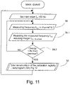
- This recalculation of the calibration registry is shown as a flow diagram in Figures 11 and 12 , corresponding to the different kind of graphical presentation in Figures 6 - 8 .
- the momentary frequency is read (58) and the value is rounded to an integer (59.1), after which it is compared with the previous value (59.2), in which there is the condition 'Is there a change of at least 1 Hz from the previous?', and performance of the program continues, either as a loop directly through a preset delay to measurement of the frequency (NO), or to the recalculation procedure (50), Figure 12 .
Landscapes
- Physics & Mathematics (AREA)
- General Physics & Mathematics (AREA)
- Nonlinear Science (AREA)
- Engineering & Computer Science (AREA)
- Power Engineering (AREA)
- Measurement Of Current Or Voltage (AREA)
Description
- The present invention relates to a method for measuring alternating-current system quantities through measurement connections producing frequency-dependent errors according to the preamble of
claim 1. - The invention also relates to a corresponding system and computer program for implementing the method.
- Though the invention generally concerns 3-phase systems, it can also be applied in single-phase electrical systems.
- The frequency measurement of electric-power networks is an important part of the monitoring and control of an electric-power network. Many different frequency protections and control automation are based on the use of frequency measurement. On the basis of frequency measurement various electric-power network components can be protected from overloading and detrimental frequencies. In addition, frequency measurement can be used as a basis for controlling generators. Frequency measurement is also used for power and energy calculation, on which the selling and buying of electricity are based.
- Various frequency meters are known from the prior art, which convert the current and voltage signals of an electric-power network into phase angle and magnitude, using so-called Fourier transformation, particularly FFT (Fast Fourier Transform) calculation. Wavelet analysis can also be used. Stated generally, periodic signals are examined using the chosen frequency analysis. The analog signal is sampled at a specific constant frequency through the measurement range.
- The problem with such a technique is that it does not take into account the measurement error created by frequency differences. If the sampling frequency is, for example, a fixed 50 Hz, and the measured voltage of the electric-power network is 60 Hz, the magnitude of the measurement error will be already about 5 % in the different phases of the current.
- Patent publication
US 5,014,229 presents method comprising sampling of an analog signal, calculating plurality of harmonic signals, correction of each harmonic signal and finally combining harmonic signals to one calibrated signal. Correction tables for each harmonic frequency are used. The tables contain non-linearity amplitude and phase shift correction curves. - Patent publication
US 5,832, 414 presents a method compensating for errors in phasor estimation due to oscillations caused by discrete fourier transforms used to estimate signal frequency. - Patent publication
US 5,151,866 presents a method rapidly and continuously sampling AV voltage and current signals. The deviation from sine signal is detected in a zero-crossing point. - Patent publication
US 8,108,165 B2 is known from the prior art and discloses one frequency meter, which uses frequency-dependent sampling of analog signals. Frequency-dependent sampling is used over the entire measurement range of 6 - 75 Hz (more generally 5 - 100 Hz). If the measured frequency is outside the measurement range, the lowest or highest sampling frequency and a correction factor, which seeks to compensate for the error, are used in the measurement. Despite the frequency-dependent sampling, considerable measurement errors appear in frequency measurement of this kind, as the measurement does not take into account the error caused by the components of the measurement card. - The invention is intended to create a method that is more accurate and reliable than methods of the prior art for measuring frequency in an electric-power network. The characteristic features of the method according to the present invention are stated in the accompanying
Claim 1 and the features of the system applying the method are stated inClaim 9. As, according to the invention, the non-linearity of the analog component of each measurement connection is calibrated at different frequencies and a frequency-dependent correction function is created, the method according to the invention gives an extremely accurate result over a wide frequency range. The frequency-dependent correction is preferably made to the magnitude and phase-angle values of several frequency components. The correction function is preferably a matrix, in the elements corresponding to a specific input are the correction values for discrete frequencies. These can be used in a stepped manner, but it is preferable to interpolate the intermediate values. Extreme values can be used outside the nominal frequency range. - The magnitude and/or phase-angle values are preferably calculated for 7 - 64, preferably 15 - 31 harmonic frequency components.
- In one embodiment, the device is calibrated magnitudedependently and a similar correction table is created. The actual correction calculation is entirely the same as that described in connection with the frequency-dependent correction table.
- In the following, the invention is described in detail with reference to the accompanying drawings depicting some embodiments of the invention, in which
- Figure 1
- shows the wiring of the protection device in monitoring a 3-phase feeder line,
- Figure 2
- shows the analog measurement connections of five current-measurement channels on a special analog card,
- Figure 3
- shows the conversion of values obtained from an A/D converter into current values,
- Figure 4
- shows a general view of the processing of each sequence,
- Figure 5
- shows the correction to be made for each frequency component,
- Figures 6, 7, and 8
- show the programmatic updating arrangement of five correction tables of a current-measurement channel,
- Figure 9a
- shows the error of a known measurement as a function of frequency,
- Figure 9b
- shows the error of frequency measurement according to the invention using 3-phase currents,
- Figure 10
- shows a flow diagram of an example of the frequency correction of voltage measurement,
- Figure 11
- shows a flow diagram of a main program initiating the re-calculation of a correction table,
- Figure 12
- shows a flow diagram of the re-calculation.
- The
protection device 20 ofFigure 1 monitors a branch line, which is connected to acable terminal 14, connected to themain line 16. Feed to the branch line, which is depicted by thecable terminal 14, is taken from the phases L1, L2, L3 of themain line 16. The branch line is protected by a 3-phase circuit breaker 12 and anearthing switch 13. Thecircuit breaker 12 is controlled by a smart protectingdevice 20. This can measure the voltage inputs U1 - U4, and current inputs IL1 - IL3, I01 and 102. The operating device of the 3-phase circuit breaker 12, and the state detector of theearthing switch 13 are connected to the outputs D01 - D04 of the I/O component 22. Theearthing switch 13 is manually operated, but state data are taken from it through the I/O component 22 to theprotection device 20, which prevents thecircuit breaker 12 from closing, if the earthing is switched on. - Voltage detection uses a common star-connected primary-
coil series 29. The voltage inputs U1 - U3 (phase voltages) use a star-connected secondary-coil series 28 and the zero voltage to the voltage input U4 is formed by the open-delta connection 27 of the voltage converters. The voltages are taken to the voltage-checkingconverters 26 of the protection device. - The current detection IL1, IL2, IL3 of the phases of the feed line uses inductively connected coils 15 in each phase conductor. In addition, the current I01 of the earth conductor of the cable terminal is detected by means of a coil 15.1. In this case, the
current input 102 is not in use. The current measurements are taken to the current-measurement transformer 24. - A precondition of first-class operation is the precise measurement of the phase quantities, which, when the frequency varies, is challenging, because conventional measurement electronics only operate well at the nominal frequency, for example, 50 Hz.
- The input of the current and voltage measurements consists of analog components, which may have a considerable divergence in electrical properties, particularly farther from the nominal frequency.
-
Figure 2 shows the configuration of the current-measurements' inputs as far as the A/D converter. The four voltage-measurement chains are in a corresponding manner on a different card (not shown). All the analog components are installed on a specialreplaceable circuit card 21, in which there is also a non-volatile memory 21.1 and its connection means 21.2. The significance of this memory will become apparent later. The analog components, including the A/D converter, in each measurement circuit form a main non-linearity. In the chain from left to right are: acurrent transformer 22, a shunt resistance 'Shx' 24.1, voltage divider resistances 24.2, an analog filter 24.3, an amplifier 24.4, and finally the A/D converter 24.5 itself. The same is also true of the voltage-measurement circuits (not shown). - Each analog signal is sampled at the A/D converter at a multiple of the approximately measured frequency fm (6 - 75 Hz, tolerance about 100 mHz) creating a base series depicting the period in such a way that the samples of the period form a fundamental-wave length FFT buffer for each measurement channel of essentially one entire electrical period (e.g, the fundamental wave of a 50-Hz electrical period is 20 ms). The A/D converter is controlled by a sampling signal S brought from the host processor, the frequency of which fs is adjusted according to the approximately measured base frequency fm, preferably using the equation:

-
Figures 3 - 8 show schematically software implementations of the calculation. -
Figure 3 shows the conversion of raw values 24.6 obtained from the A/D converter into current values. The A/D converter's reading range -132000...+132000 corresponds, for example, to a current range of 0...100 A. The conversion takes place by fetching from a lookup table 24.7 a channel-specific scaling factor, which is taken together with the value to a multiplier 24.8. This is not important in terms of the invention. - In
Figure 4 , each channels' base series, i.e. the FFT buffer, is taken toFFT transformation 31, which calculates, in addition to thebase frequency 31, the root-mean-square RMS of the magnitude and the phase angle of the harmonic frequency component. From theFFT calculation 31 are obtained 64 vectors, 32 of which are mirror images, which are terminated at theselector 32.Figure 4 mainly follows the processing of a single frequency component. Here, FFT computation is an effective numerical form of calculation for performing Fourier analysis. The Wavelet technique would provide advantages in the calculation of offset currents and impedance protectors. The necessary frequency analysis can also be made using some other method. - The 32 vectors selected for further processing are scaled to form root-mean-square values in the multiplier 33 (complex vector x (sqrt(2) / number of samples)). After this, the vector of each frequency component (in this case current) is taken to the
calibration correction module 34, which is shown in greater detail inFigure 5 . As result, the calibrated vector (output 1)of each frequency component is obtained. From this, a separate magnitude value (output 2) and phase angle (output 4) is formed by acartesian converter 38. A precise true-root-mean-square value TRMS (output 3) is formed in thecalculator 39 from the magnitude values of all the frequency components. It is obtained by taking the square root of the sum of the squares of the magnitude values (32 items). - An approximate maximum value (output 5), which can be used for the approximate adjustment of later stages, for example, is formed from the uncalibrated input signal by the
calculator 38. -
Figure 5 shows the operation of the saidcalibrationcorrection module 34, which is essential to the present invention. The vector (e.g., 100 V, j100 V) obtained from theinput 41 is divided by thecartesian converter 44 into separate magnitude and phase-angle values (|142 V|, ∠45°), for which a separate calibration correction is made with the aid of pre-calculated frequency-dependent correction factors. In the case ofFigure 5 , the processing is base-frequency correction, because the correction factor is read at theclock pulse 0. The vector's first correction factor is 40.0. The channel-specific magnitude correction factor is read from the registry 42.M 'M1CT1_ IL1MCF1U' (channel IL1) and is taken to themultiplier 46, in which it is multiplied by the measured value. Correspondingly, the channel-specific phase-angle correction factor is read from the registry 42.A 'M1CT1_ IL1ACF1U' (channel IL1) and taken to thesummer 48, where it is summed with the retrieved phase angle. Finally, the calibrated values obtained are converted back to vector values by polar conversion and sent to the output 50 'Cal_out' . - Calibration corrections according to
Figure 5 are made on each channel (5 current and 4 voltage-measurement channels) and in each of these for each frequency component (32 items). Calibration coefficients, which are applied to discrete frequencies, and which are obtained in special calibration calculation, are stored in the memory 21.1 (Figure 2 ) of thecircuit card 21. From there, they are retrieved for use by the host processor, which calculates momentary values corresponding to the frequency in the said registries 42.M and 42.A (in this case M1CT1_IL1MCF1U and M1CT1_IL1ACF1U). As the calibrated correction factors are stored in the circuit card's memory 21.1, it can be changed rapidly and the new circuit card together with the stored correction matrices will provide accurate results immediately. - By calibrating the magnitude and phase angle of the harmonic frequency components, TRMS (True Root Mean Square), the measurements using the different harmonic components and depending on multiple frequencies become accurate, which would otherwise depend entirely on the properties of the available measurement techniques, especially at higher harmonic frequencies. The measurement technique typically measures accurately only at the fixed frequency of the fundamental wave.
-
Figures 6 ,7 , and8 show the software updating of the correction factors of the current measurements IL1, IL2, IL3, I01, and 102 according to the frequency at the time. - Corresponding calculation is made in the case of voltage measurement. The system's host processor includes a CPU, RAM/ROM memories, and I/O means, as well as an operating system for running the computation software.
- Each current input has separate magnitude and phase-angle correction tables. The momentary calibration values for each channel are stored in
registries 52. Controlled by the clock pulse, the outputs 51.M (magnitude) and 51.A (phase angle) read the momentary discrete correction values Y1 - Y8 to theapproximation calculation modules 54 and 55 (magnitude and phase angles separately, on all channels). The same clock pulse controls the reading of the discrete frequency values (6, 15, 25, 30, 40, 50, 60, and 75 Hz), with which the calibration is made, for all thecalculation modules - X=[X1, X2, X3, X4, X5, X6, X7, X8]; the frequency-dependence factor is an 8-place vector (discrete frequencies 6 - 75 Hz);
- Y=[Y1, Y2, Y3, Y4, Y5, Y6, Y7, Y8]; the magnitude or phase-angle correction factor is an 8-place vector, in which there are factors corresponding to the discrete frequencies;
- The discrete frequency X(i) immediately below the measured frequency 'freq' and the corresponding factor Y(i) are sought. The correction value is freqk = (Y(i) + ((freq-X(i)) * ((Y(i + 1) - Y(i)) / (X(i + 1) - X(i))))).
- The extreme values Y1 and Y8 of the factors are used above and below the discrete frequencies. The calculated factor is taken to the magnitude/phase-angle registry of the corresponding channel, e.g., the magnitude correction factor of the channel IL1 to the registry M1CT1_IL1MCF1_1' (56.M.IL1).
- The analog front-end design has a considerable effect on the number of the calibration frequencies required and their selection. If the design is not linear, the desired accuracy can be achieved by increasing the number of calibration points. Similarly, a linear approximation between the discrete points is not necessarily required, if there is a sufficiently large number of discrete points.
- In the following is an example of a correction table, in which there are the magnitude and angle correction values of different current-measurement channels IL1, IL2, IL3, I01, and 102 at the discrete frequencies 6 - 75 Hz (8 items).
Table 1 freq [Hz] IL1Cf IL2Cf IL3Cf I01Cf I02Cf 6 1.00870 1.00855 1.00673 0.90746 0.86719 15 1.00758 1.00756 1.00554 0.94732 0.90845 25 1.00758 1.00776 1.00565 0.98543 0.97558 30 1.00763 1.00774 1.00569 0.98928 0.98439 40 1.00842 1.00855 1.00617 0.98968 0.98666 50 1.00832 1.00836 1.00634 0.99051 0.98772 60 1.00815 1.00836 1.00573 0.99094 0.98884 75 1.00773 1.00802 1.00579 0.99111 0.98925 freq [Hz] IL2ang IL3ang I01ang I02ang 6 -0.03 0.00 -4.63 -4.23 15 -0.02 0.00 -2.53 -2.70 25 -0.01 0.00 -0.88 -1.28 30 -116.94 -0.02 -0.42 -0.69 40 20.52 0.01 -0.28 -0.47 50 0.00 0.00 -0.18 -0.32 60 -0.01 0.00 -0.12 -0.25 75 -0.01 0.00 -0.11 -0.19 - The angle value of channel IL1 acts as a reference for the angle values of the other channels.
- These values are stored in the card's
memory 21, from where they are read to the processor's RAM memory in connection with the initialization relating to starting the device. - Table 1 shows the application's calibrated frequency-dependent function k(fn), with the aid of which each measurement connection the said error is eliminated.
- In the calculation model of
Figures 6 - 8 , the momentary values according to each frequency are picked from this table to the calculation registries, by which the measurement values are then calibrated. The calculation registries are updated according to selected criterion. - According to
Figure 8 , the approximately measured frequency in Herz is rounded by the unit 59.1 (cell-function) to an integer. The condition module 59.2 triggers a new calculation, if the measured frequency has changed by at least 1 Hz from the previous 5-ms round of calculation. Theblock 50 contains the functions ofFigures 6 and7 . The memory-location readings 57 shown inFigure 8 depict the predefined calibration frequency points. - In general, the core of the system is a computer program, which comprises program code for implementing the method described.
- The apparent output is calculated using the, as such, known equation:


- From this the effective output and reactive output are calculated using the equations:


- Accurate calculation requires also taking the harmonic frequency components into account, in which case the apparent output of each phase is calculated as the sum of the frequency components, as follows:

- After this, the aforementioned effective-output and reactiveoutput equations can be applied.
- According to
Figures 9a and 9b , the calculation system according to the invention provides significant frequency stability. According toFigure 9a , the conventional measurement technique for phase quantities is accurate only at the nominal frequency, in thiscase 50 Hz. The error in the range 6 - 75 Hz can be as much as tens of percent. Generally, the error is greater the farther one goes from the nominal frequency and the larger the multiple frequency that is being examined. - The errors of the measurement card according to the invention, for example, at different phase currents, are, according to
Figure 9b , less than 0.25 % over the entire frequency range (6 - 75 Hz). -
Figure 10 shows the measurement procedure ofFigures 2 ,3 ,4 , and5 as a flow diagram (here the voltage u is being measured). The momentary correction values are marked with the quantities 'Ci' (46) and 'αi' (48). In the software implementation, the challenge is the large number of realtime calculations, because each separate sampled measurement vector is divided, in this case, into 32 separate vectors, on which a polar conversion is performed, so that there are 64 values to be corrected in each period. The processor operates in 5-ms periods, so that there are 115 200 correction calculations (46, 48) per second in nine channels. The computing power of the prototype system is 300 Megaflops, which is more than enough for the calculation. When the frequency changes, the correction registry must be recalculated (Figures 6 ,7 , and8 , as well as the flow diagrams ofFigures 11 and12 ), so that Fourier or similar transformation must be carried out on the data flow of each channel, and the number of calculation operations required continues to increase. Thus, a frequency tolerance of 1 Hz (generally 0.4 - 2.5 Hz) has been observed to be optimal in terms of accuracy and computational capacity. - This recalculation of the calibration registry is shown as a flow diagram in
Figures 11 and12 , corresponding to the different kind of graphical presentation inFigures 6 - 8 . The momentary frequency is read (58) and the value is rounded to an integer (59.1), after which it is compared with the previous value (59.2), in which there is the condition 'Is there a change of at least 1 Hz from the previous?', and performance of the program continues, either as a loop directly through a preset delay to measurement of the frequency (NO), or to the recalculation procedure (50),Figure 12 . - From the flow diagram of the recalculation procedure (
Figure 12 ), it can be seen that three indices (i, k, 1) and two nested loops are required in the calculation. If the measured frequency is, for example, 41.5 Hz, it lies between 40 Hz (X4) and 50 Hz (X5), when the index I = 4 and the element (Y4, 1, k and Y5, 1, k) is taken from each calibration table 4. and 5. to the linear approximation.
Claims (12)
- Method for measuring alternating-current system quantities through measurement channels producing frequency-dependent errors, the method comprising steps ofa) producing an analog signal through each channel (IL1-3, 101, 102), depicting a selected current/voltage quantity (22, 24.1-4), andb) sampling at least one analog signal (24.5) at a frequency fs being a multiple of an approximately measured frequency fm, creating a base series depicting a period on the corresponding measurement channel (IL1, IL2, IL3, 101, 102),c) calculating from each base series obtained, values of a base frequency and a magnitude and/or a phase-angle, of at least one harmonic frequency component with the aid of a selected frequency analysis (31, 32),d) correcting each calculated magnitude and/or phase-angle value with the aid of a calibrated frequency-dependent function k(fn) (34) giving a frequency dependent correction value for each calculated value, in order to eliminate the said error of each measurement channel and obtaining calibrated magnitude and/or phase-angle values,e) calculating the selected quantities, from the calibrated magnitude and/or phase-angle values,characterized in that momentary frequency-dependent correction values are produced with a correction function for the calculation when the approximately measured frequency fm changes by more than a selected criterion.
- Method according to Claim 1, characterized in that each correction function comprises a table containing discrete correction values at the selected calibration frequencies.
- Method according to any of Claims 1 - 2, characterized in that the magnitude and/or phase-angle values are calculated for 7 - 64, preferably 15 - 31 harmonic frequency components.
- Method according to any of Claims 1 - 3, characterized in that the said measurement range is 5 - 100 Hz, preferably 6 - 75 Hz.
- Method according to any of Claims 1 - 4, characterized in that the selected analysis belongs to the group: conventional Fourier, FFT, Wavelet analysis.
- Method according to any of Claims 1 - 5, characterized in that each measurement channel is also calibrated magnitudedependently.
- Method according to any of Claims 1 - 6, characterized in that FFT calculation is used and the sampling frequency is set continuously relative to the measured frequency fm using the equation

- System for measuring alternating-current quantities, which system includesa) an analog component (22, 24.1-4) comprising several measurement channels (IL1-3, 101, 102), each for producing an analog signal depicting a selected current/voltage quantity, andb) means (24.5) for sampling each analog signal at a frequency fs being a multiple of an approximately measured frequency fm, creating a base series depicting a period on each measurement channel (IL1, IL2, IL3, 101, 102), andc) frequency-analysis means for calculating values of a base frequency and a magnitude and/or a phase-angle, of at least one harmonic frequency component from each of the base series obtained, andd) means (34) for correcting each calculated magnitude and/or phase-angle value with the aid of a calibrated frequency-dependent function k(fn) giving a frequency dependent correction value for each calculated value in order to eliminate the said error in each measurement channel and for obtaining calibrated magnitude and/or phase-angle values, ande) means for calculating the selected quantities, from the calibrated magnitude and/or phase-angle values,characterized in that the said correction function k(fn) comprises a correction table containing pre-calculated frequency-dependent discrete correction values stored in memory means and calculation means for performing the selected approximation according to the measured frequency.
- System according to Claim 8, characterized in that the system includes at least one measurement card (21) comprising an analog component and an A/D converter (24.5) of one measurement channel.
- System according to Claim 9, characterized in that the said measurement card (21) includes the analog components of several channels and a non-volatile memory (21.1) arranged to store the calibration factors of the measurement card.
- System according to any of Claims 8 - 10, wherein the system further includes a CPU, RAM/ROM memories, and I/O means, as well as an operating system
- Computer program, which comprises program code to cause the system of claim 11 to execute the steps of the method according to any of Claims 1 - 7.
Applications Claiming Priority (2)
| Application Number | Priority Date | Filing Date | Title |
|---|---|---|---|
| FI20135835A FI124421B (en) | 2013-08-16 | 2013-08-16 | Procedures and systems for measuring quantities in an AC system |
| PCT/FI2014/050628 WO2015022451A1 (en) | 2013-08-16 | 2014-08-15 | Method and system and computer program for measuring alternating-current system quantities |
Publications (3)
| Publication Number | Publication Date |
|---|---|
| EP3036550A1 EP3036550A1 (en) | 2016-06-29 |
| EP3036550A4 EP3036550A4 (en) | 2017-04-05 |
| EP3036550B1 true EP3036550B1 (en) | 2022-05-11 |
Family
ID=51398979
Family Applications (1)
| Application Number | Title | Priority Date | Filing Date |
|---|---|---|---|
| EP14836412.8A Active EP3036550B1 (en) | 2013-08-16 | 2014-08-15 | Method and system and computer program for measuring alternating-current system quantities |
Country Status (6)
| Country | Link |
|---|---|
| US (1) | US20160195574A1 (en) |
| EP (1) | EP3036550B1 (en) |
| ES (1) | ES2922849T3 (en) |
| FI (1) | FI124421B (en) |
| PL (1) | PL3036550T3 (en) |
| WO (1) | WO2015022451A1 (en) |
Families Citing this family (7)
| Publication number | Priority date | Publication date | Assignee | Title |
|---|---|---|---|---|
| EP3153872A1 (en) | 2015-10-06 | 2017-04-12 | ABB Schweiz AG | Method and system for determining phasor components of a periodic waveform |
| CN106405295B (en) * | 2016-10-18 | 2019-03-01 | 广州供电局有限公司 | The condition detection method of analog quantity of power distribution terminal input channel, device and system |
| CN107561351B (en) * | 2017-09-14 | 2019-09-27 | 河南工程学院 | The output voltage current detection means and rapid analysis method of grid-connected inverting system |
| WO2021152789A1 (en) * | 2020-01-30 | 2021-08-05 | 東芝三菱電機産業システム株式会社 | System frequency detector |
| CN112098724B (en) * | 2020-09-07 | 2023-06-30 | 青岛鼎信通讯股份有限公司 | Relay DFT harmonic detection method applied to linear transformation relation identifier |
| CN113189532B (en) * | 2021-04-23 | 2023-01-13 | 国家电网有限公司 | Online correction method and device for harmonic measurement error of capacitor voltage transformer |
| US20230052689A1 (en) * | 2021-08-13 | 2023-02-16 | Texas Instruments Incorporated | Magnetic sensor array processing for interference reduction |
Family Cites Families (15)
| Publication number | Priority date | Publication date | Assignee | Title |
|---|---|---|---|---|
| US5014229A (en) * | 1989-02-08 | 1991-05-07 | Basic Measuring Instruments | Method and apparatus for calibrating transducer/amplifier systems |
| US5151866A (en) | 1990-03-30 | 1992-09-29 | The Dow Chemical Company | High speed power analyzer |
| US5406495A (en) * | 1993-02-01 | 1995-04-11 | Systems Analysis And Integration, Inc. | Substation load distribution monitor system |
| TW327223B (en) | 1993-09-28 | 1998-02-21 | Sony Co Ltd | Methods and apparatus for encoding an input signal broken into frequency components, methods and apparatus for decoding such encoded signal |
| US8505108B2 (en) * | 1993-11-18 | 2013-08-06 | Digimarc Corporation | Authentication using a digital watermark |
| US5832414A (en) * | 1995-12-18 | 1998-11-03 | Abb Power T&D Company Inc. | Generator protection system and method of compensating for errors in phasor estimation due to oscillations in discrete Fourier transform |
| US6934654B2 (en) * | 2003-03-21 | 2005-08-23 | Schweitzer Engineering Laboratories, Inc. | System and method for exact compensation of fundamental phasors |
| US7444248B2 (en) * | 2005-04-29 | 2008-10-28 | General Electric Company | System and method for synchronized phasor measurement |
| PL1936391T3 (en) * | 2006-12-19 | 2011-08-31 | Abb Schweiz Ag | Apparatus and method for improving the accuracy of instrument transformers |
| US8108165B2 (en) | 2008-04-04 | 2012-01-31 | Schweitzer Engineering Laboratories, Inc. | Acquiring phasors outside the frequency tracking range for power protective relays |
| US8140283B2 (en) * | 2008-12-24 | 2012-03-20 | Schweitzer Engineering Laboratories, Inc. | Independent frequency measurement and tracking |
| US8346402B2 (en) * | 2009-05-11 | 2013-01-01 | Schweitzer Engineering Laboratories Inc | Islanding detection in an electrical power delivery system |
| US8564308B2 (en) * | 2009-09-30 | 2013-10-22 | Tektronix, Inc. | Signal acquisition system having reduced probe loading of a device under test |
| US9037429B2 (en) * | 2011-06-06 | 2015-05-19 | Siemens Industry, Inc. | Methods and apparatus for measuring the fundamental frequency of a line signal |
| CN103063913B (en) * | 2012-12-07 | 2016-01-20 | 深圳市金宏威技术有限责任公司 | For the frequency tracking method of Fourier transform |
-
2013
- 2013-08-16 FI FI20135835A patent/FI124421B/en active IP Right Grant
-
2014
- 2014-08-15 US US14/912,111 patent/US20160195574A1/en not_active Abandoned
- 2014-08-15 WO PCT/FI2014/050628 patent/WO2015022451A1/en active Application Filing
- 2014-08-15 PL PL14836412.8T patent/PL3036550T3/en unknown
- 2014-08-15 EP EP14836412.8A patent/EP3036550B1/en active Active
- 2014-08-15 ES ES14836412T patent/ES2922849T3/en active Active
Also Published As
| Publication number | Publication date |
|---|---|
| ES2922849T3 (en) | 2022-09-20 |
| PL3036550T3 (en) | 2022-08-22 |
| FI20135835A (en) | 2014-08-29 |
| US20160195574A1 (en) | 2016-07-07 |
| EP3036550A4 (en) | 2017-04-05 |
| EP3036550A1 (en) | 2016-06-29 |
| FI124421B (en) | 2014-08-29 |
| WO2015022451A1 (en) | 2015-02-19 |
Similar Documents
| Publication | Publication Date | Title |
|---|---|---|
| EP3036550B1 (en) | Method and system and computer program for measuring alternating-current system quantities | |
| US10809287B2 (en) | Method and system and computer program for measuring alternating-current system quantities | |
| US6185508B1 (en) | Power meter for determining parameters of multi-phase power lines | |
| US8108165B2 (en) | Acquiring phasors outside the frequency tracking range for power protective relays | |
| US10345416B2 (en) | Intelligent electronic device with broad-range high accuracy | |
| US6946847B2 (en) | Impedance matching device provided with reactance-impedance table | |
| US7996171B2 (en) | Intelligent electronic device with broad-range high accuracy | |
| US6429637B1 (en) | Electronic power meter with phase and non-linearity compensation | |
| US6507184B1 (en) | Methods and apparatus for differential current measurement in a three-phase power system | |
| US5606510A (en) | High speed power analyzer | |
| US20150244342A1 (en) | High frequency matching system | |
| WO2003021279A1 (en) | Methods and apparatus for phase compensation in electronic energy meters | |
| US6989977B2 (en) | Digital directional relay | |
| JP6084418B2 (en) | Impedance adjustment device | |
| US7746057B2 (en) | Power meter having complex quadrature output current and voltage filters | |
| CA2414750C (en) | Method and apparatus employing a scaling factor for measuring and displaying an electrical parameter of an electrical system | |
| CN112816754B (en) | Current compensation method and equipment for current transformer | |
| US7218015B2 (en) | Method of providing a constant AC voltage to a remote variable load | |
| AU2003204811B2 (en) | Power-related amount measurement device | |
| JP2017135117A (en) | Impedance adjustment method for high frequency matching system | |
| JP2011141196A (en) | Insulation monitoring device | |
| EP0801745B1 (en) | Measuring method for determining the amplitude and phase of the fundamental tone of an alternating voltage | |
| CN104009488A (en) | AC power supply apparatus | |
| JPH04168907A (en) | Overexcitation detecting relay unit | |
| Juvik et al. | Calibration system and uncertainty budget for instrument transformers with digital output |
Legal Events
| Date | Code | Title | Description |
|---|---|---|---|
| PUAI | Public reference made under article 153(3) epc to a published international application that has entered the european phase |
Free format text: ORIGINAL CODE: 0009012 |
|
| 17P | Request for examination filed |
Effective date: 20160314 |
|
| AK | Designated contracting states |
Kind code of ref document: A1 Designated state(s): AL AT BE BG CH CY CZ DE DK EE ES FI FR GB GR HR HU IE IS IT LI LT LU LV MC MK MT NL NO PL PT RO RS SE SI SK SM TR |
|
| AX | Request for extension of the european patent |
Extension state: BA ME |
|
| DAX | Request for extension of the european patent (deleted) | ||
| A4 | Supplementary search report drawn up and despatched |
Effective date: 20170308 |
|
| RIC1 | Information provided on ipc code assigned before grant |
Ipc: G01R 21/00 20060101ALI20170302BHEP Ipc: G01R 23/02 20060101AFI20170302BHEP Ipc: G01R 19/25 20060101ALI20170302BHEP Ipc: G01R 23/15 20060101ALI20170302BHEP Ipc: G01R 19/00 20060101ALI20170302BHEP |
|
| STAA | Information on the status of an ep patent application or granted ep patent |
Free format text: STATUS: EXAMINATION IS IN PROGRESS |
|
| 17Q | First examination report despatched |
Effective date: 20200323 |
|
| STAA | Information on the status of an ep patent application or granted ep patent |
Free format text: STATUS: EXAMINATION IS IN PROGRESS |
|
| GRAP | Despatch of communication of intention to grant a patent |
Free format text: ORIGINAL CODE: EPIDOSNIGR1 |
|
| STAA | Information on the status of an ep patent application or granted ep patent |
Free format text: STATUS: GRANT OF PATENT IS INTENDED |
|
| INTG | Intention to grant announced |
Effective date: 20211207 |
|
| GRAS | Grant fee paid |
Free format text: ORIGINAL CODE: EPIDOSNIGR3 |
|
| GRAA | (expected) grant |
Free format text: ORIGINAL CODE: 0009210 |
|
| STAA | Information on the status of an ep patent application or granted ep patent |
Free format text: STATUS: THE PATENT HAS BEEN GRANTED |
|
| AK | Designated contracting states |
Kind code of ref document: B1 Designated state(s): AL AT BE BG CH CY CZ DE DK EE ES FI FR GB GR HR HU IE IS IT LI LT LU LV MC MK MT NL NO PL PT RO RS SE SI SK SM TR |
|
| RAP3 | Party data changed (applicant data changed or rights of an application transferred) |
Owner name: ARCTEQ RELAYS OY |
|
| REG | Reference to a national code |
Ref country code: GB Ref legal event code: FG4D |
|
| REG | Reference to a national code |
Ref country code: CH Ref legal event code: EP |
|
| REG | Reference to a national code |
Ref country code: AT Ref legal event code: REF Ref document number: 1491862 Country of ref document: AT Kind code of ref document: T Effective date: 20220515 |
|
| REG | Reference to a national code |
Ref country code: DE Ref legal event code: R096 Ref document number: 602014083726 Country of ref document: DE |
|
| REG | Reference to a national code |
Ref country code: IE Ref legal event code: FG4D |
|
| REG | Reference to a national code |
Ref country code: FI Ref legal event code: FGE |
|
| REG | Reference to a national code |
Ref country code: SE Ref legal event code: TRGR |
|
| REG | Reference to a national code |
Ref country code: LT Ref legal event code: MG9D |
|
| REG | Reference to a national code |
Ref country code: NL Ref legal event code: MP Effective date: 20220511 |
|
| REG | Reference to a national code |
Ref country code: ES Ref legal event code: FG2A Ref document number: 2922849 Country of ref document: ES Kind code of ref document: T3 Effective date: 20220920 |
|
| REG | Reference to a national code |
Ref country code: AT Ref legal event code: MK05 Ref document number: 1491862 Country of ref document: AT Kind code of ref document: T Effective date: 20220511 |
|
| PG25 | Lapsed in a contracting state [announced via postgrant information from national office to epo] |
Ref country code: PT Free format text: LAPSE BECAUSE OF FAILURE TO SUBMIT A TRANSLATION OF THE DESCRIPTION OR TO PAY THE FEE WITHIN THE PRESCRIBED TIME-LIMIT Effective date: 20220912 Ref country code: NO Free format text: LAPSE BECAUSE OF FAILURE TO SUBMIT A TRANSLATION OF THE DESCRIPTION OR TO PAY THE FEE WITHIN THE PRESCRIBED TIME-LIMIT Effective date: 20220811 Ref country code: NL Free format text: LAPSE BECAUSE OF FAILURE TO SUBMIT A TRANSLATION OF THE DESCRIPTION OR TO PAY THE FEE WITHIN THE PRESCRIBED TIME-LIMIT Effective date: 20220511 Ref country code: LT Free format text: LAPSE BECAUSE OF FAILURE TO SUBMIT A TRANSLATION OF THE DESCRIPTION OR TO PAY THE FEE WITHIN THE PRESCRIBED TIME-LIMIT Effective date: 20220511 Ref country code: HR Free format text: LAPSE BECAUSE OF FAILURE TO SUBMIT A TRANSLATION OF THE DESCRIPTION OR TO PAY THE FEE WITHIN THE PRESCRIBED TIME-LIMIT Effective date: 20220511 Ref country code: GR Free format text: LAPSE BECAUSE OF FAILURE TO SUBMIT A TRANSLATION OF THE DESCRIPTION OR TO PAY THE FEE WITHIN THE PRESCRIBED TIME-LIMIT Effective date: 20220812 Ref country code: BG Free format text: LAPSE BECAUSE OF FAILURE TO SUBMIT A TRANSLATION OF THE DESCRIPTION OR TO PAY THE FEE WITHIN THE PRESCRIBED TIME-LIMIT Effective date: 20220811 Ref country code: AT Free format text: LAPSE BECAUSE OF FAILURE TO SUBMIT A TRANSLATION OF THE DESCRIPTION OR TO PAY THE FEE WITHIN THE PRESCRIBED TIME-LIMIT Effective date: 20220511 |
|
| PG25 | Lapsed in a contracting state [announced via postgrant information from national office to epo] |
Ref country code: RS Free format text: LAPSE BECAUSE OF FAILURE TO SUBMIT A TRANSLATION OF THE DESCRIPTION OR TO PAY THE FEE WITHIN THE PRESCRIBED TIME-LIMIT Effective date: 20220511 Ref country code: LV Free format text: LAPSE BECAUSE OF FAILURE TO SUBMIT A TRANSLATION OF THE DESCRIPTION OR TO PAY THE FEE WITHIN THE PRESCRIBED TIME-LIMIT Effective date: 20220511 Ref country code: IS Free format text: LAPSE BECAUSE OF FAILURE TO SUBMIT A TRANSLATION OF THE DESCRIPTION OR TO PAY THE FEE WITHIN THE PRESCRIBED TIME-LIMIT Effective date: 20220911 |
|
| PG25 | Lapsed in a contracting state [announced via postgrant information from national office to epo] |
Ref country code: SM Free format text: LAPSE BECAUSE OF FAILURE TO SUBMIT A TRANSLATION OF THE DESCRIPTION OR TO PAY THE FEE WITHIN THE PRESCRIBED TIME-LIMIT Effective date: 20220511 Ref country code: SK Free format text: LAPSE BECAUSE OF FAILURE TO SUBMIT A TRANSLATION OF THE DESCRIPTION OR TO PAY THE FEE WITHIN THE PRESCRIBED TIME-LIMIT Effective date: 20220511 Ref country code: RO Free format text: LAPSE BECAUSE OF FAILURE TO SUBMIT A TRANSLATION OF THE DESCRIPTION OR TO PAY THE FEE WITHIN THE PRESCRIBED TIME-LIMIT Effective date: 20220511 Ref country code: EE Free format text: LAPSE BECAUSE OF FAILURE TO SUBMIT A TRANSLATION OF THE DESCRIPTION OR TO PAY THE FEE WITHIN THE PRESCRIBED TIME-LIMIT Effective date: 20220511 Ref country code: DK Free format text: LAPSE BECAUSE OF FAILURE TO SUBMIT A TRANSLATION OF THE DESCRIPTION OR TO PAY THE FEE WITHIN THE PRESCRIBED TIME-LIMIT Effective date: 20220511 Ref country code: CZ Free format text: LAPSE BECAUSE OF FAILURE TO SUBMIT A TRANSLATION OF THE DESCRIPTION OR TO PAY THE FEE WITHIN THE PRESCRIBED TIME-LIMIT Effective date: 20220511 |
|
| REG | Reference to a national code |
Ref country code: DE Ref legal event code: R097 Ref document number: 602014083726 Country of ref document: DE |
|
| PLBE | No opposition filed within time limit |
Free format text: ORIGINAL CODE: 0009261 |
|
| STAA | Information on the status of an ep patent application or granted ep patent |
Free format text: STATUS: NO OPPOSITION FILED WITHIN TIME LIMIT |
|
| PG25 | Lapsed in a contracting state [announced via postgrant information from national office to epo] |
Ref country code: MC Free format text: LAPSE BECAUSE OF FAILURE TO SUBMIT A TRANSLATION OF THE DESCRIPTION OR TO PAY THE FEE WITHIN THE PRESCRIBED TIME-LIMIT Effective date: 20220511 Ref country code: AL Free format text: LAPSE BECAUSE OF FAILURE TO SUBMIT A TRANSLATION OF THE DESCRIPTION OR TO PAY THE FEE WITHIN THE PRESCRIBED TIME-LIMIT Effective date: 20220511 |
|
| 26N | No opposition filed |
Effective date: 20230214 |
|
| PG25 | Lapsed in a contracting state [announced via postgrant information from national office to epo] |
Ref country code: LU Free format text: LAPSE BECAUSE OF NON-PAYMENT OF DUE FEES Effective date: 20220815 |
|
| REG | Reference to a national code |
Ref country code: BE Ref legal event code: MM Effective date: 20220831 |
|
| PG25 | Lapsed in a contracting state [announced via postgrant information from national office to epo] |
Ref country code: SI Free format text: LAPSE BECAUSE OF FAILURE TO SUBMIT A TRANSLATION OF THE DESCRIPTION OR TO PAY THE FEE WITHIN THE PRESCRIBED TIME-LIMIT Effective date: 20220511 |
|
| P01 | Opt-out of the competence of the unified patent court (upc) registered |
Effective date: 20230614 |
|
| PG25 | Lapsed in a contracting state [announced via postgrant information from national office to epo] |
Ref country code: IE Free format text: LAPSE BECAUSE OF NON-PAYMENT OF DUE FEES Effective date: 20220815 |
|
| PG25 | Lapsed in a contracting state [announced via postgrant information from national office to epo] |
Ref country code: BE Free format text: LAPSE BECAUSE OF NON-PAYMENT OF DUE FEES Effective date: 20220831 |
|
| PGFP | Annual fee paid to national office [announced via postgrant information from national office to epo] |
Ref country code: IT Payment date: 20230825 Year of fee payment: 10 Ref country code: GB Payment date: 20230822 Year of fee payment: 10 Ref country code: FI Payment date: 20230816 Year of fee payment: 10 Ref country code: CH Payment date: 20230902 Year of fee payment: 10 |
|
| PGFP | Annual fee paid to national office [announced via postgrant information from national office to epo] |
Ref country code: SE Payment date: 20230816 Year of fee payment: 10 Ref country code: PL Payment date: 20230725 Year of fee payment: 10 Ref country code: FR Payment date: 20230825 Year of fee payment: 10 Ref country code: DE Payment date: 20230821 Year of fee payment: 10 |
|
| PGFP | Annual fee paid to national office [announced via postgrant information from national office to epo] |
Ref country code: ES Payment date: 20231027 Year of fee payment: 10 |
|
| PG25 | Lapsed in a contracting state [announced via postgrant information from national office to epo] |
Ref country code: HU Free format text: LAPSE BECAUSE OF FAILURE TO SUBMIT A TRANSLATION OF THE DESCRIPTION OR TO PAY THE FEE WITHIN THE PRESCRIBED TIME-LIMIT; INVALID AB INITIO Effective date: 20140815 |
|
| PG25 | Lapsed in a contracting state [announced via postgrant information from national office to epo] |
Ref country code: CY Free format text: LAPSE BECAUSE OF FAILURE TO SUBMIT A TRANSLATION OF THE DESCRIPTION OR TO PAY THE FEE WITHIN THE PRESCRIBED TIME-LIMIT Effective date: 20220511 |